JP5864605B2 - Slide stem control valve assembly and operating method thereof - Google Patents
Slide stem control valve assembly and operating method thereof Download PDFInfo
- Publication number
- JP5864605B2 JP5864605B2 JP2013546548A JP2013546548A JP5864605B2 JP 5864605 B2 JP5864605 B2 JP 5864605B2 JP 2013546548 A JP2013546548 A JP 2013546548A JP 2013546548 A JP2013546548 A JP 2013546548A JP 5864605 B2 JP5864605 B2 JP 5864605B2
- Authority
- JP
- Japan
- Prior art keywords
- stem
- actuator
- control valve
- sleeve
- hydraulic
- Prior art date
- Legal status (The legal status is an assumption and is not a legal conclusion. Google has not performed a legal analysis and makes no representation as to the accuracy of the status listed.)
- Active
Links
- 238000011017 operating method Methods 0.000 title 1
- 239000012530 fluid Substances 0.000 claims description 62
- 238000000034 method Methods 0.000 claims description 9
- 230000004044 response Effects 0.000 claims description 4
- 239000007787 solid Substances 0.000 claims 2
- 230000007423 decrease Effects 0.000 description 5
- 230000007246 mechanism Effects 0.000 description 4
- 230000008569 process Effects 0.000 description 3
- 230000006835 compression Effects 0.000 description 2
- 238000007906 compression Methods 0.000 description 2
- 230000001276 controlling effect Effects 0.000 description 2
- 239000000463 material Substances 0.000 description 2
- 238000004886 process control Methods 0.000 description 2
- 230000000007 visual effect Effects 0.000 description 2
- 230000009471 action Effects 0.000 description 1
- 238000004891 communication Methods 0.000 description 1
- 238000010586 diagram Methods 0.000 description 1
- 239000011796 hollow space material Substances 0.000 description 1
- 238000009434 installation Methods 0.000 description 1
- 230000007257 malfunction Effects 0.000 description 1
- 238000012986 modification Methods 0.000 description 1
- 230000004048 modification Effects 0.000 description 1
- 230000002093 peripheral effect Effects 0.000 description 1
- 230000001105 regulatory effect Effects 0.000 description 1
- 238000010008 shearing Methods 0.000 description 1
- 239000000126 substance Substances 0.000 description 1
Images


Classifications
-
- F—MECHANICAL ENGINEERING; LIGHTING; HEATING; WEAPONS; BLASTING
- F16—ENGINEERING ELEMENTS AND UNITS; GENERAL MEASURES FOR PRODUCING AND MAINTAINING EFFECTIVE FUNCTIONING OF MACHINES OR INSTALLATIONS; THERMAL INSULATION IN GENERAL
- F16K—VALVES; TAPS; COCKS; ACTUATING-FLOATS; DEVICES FOR VENTING OR AERATING
- F16K31/00—Actuating devices; Operating means; Releasing devices
- F16K31/12—Actuating devices; Operating means; Releasing devices actuated by fluid
- F16K31/126—Actuating devices; Operating means; Releasing devices actuated by fluid the fluid acting on a diaphragm, bellows, or the like
- F16K31/1262—Actuating devices; Operating means; Releasing devices actuated by fluid the fluid acting on a diaphragm, bellows, or the like one side of the diaphragm being spring loaded
-
- F—MECHANICAL ENGINEERING; LIGHTING; HEATING; WEAPONS; BLASTING
- F16—ENGINEERING ELEMENTS AND UNITS; GENERAL MEASURES FOR PRODUCING AND MAINTAINING EFFECTIVE FUNCTIONING OF MACHINES OR INSTALLATIONS; THERMAL INSULATION IN GENERAL
- F16K—VALVES; TAPS; COCKS; ACTUATING-FLOATS; DEVICES FOR VENTING OR AERATING
- F16K31/00—Actuating devices; Operating means; Releasing devices
- F16K31/12—Actuating devices; Operating means; Releasing devices actuated by fluid
- F16K31/122—Actuating devices; Operating means; Releasing devices actuated by fluid the fluid acting on a piston
- F16K31/1221—Actuating devices; Operating means; Releasing devices actuated by fluid the fluid acting on a piston one side of the piston being spring-loaded
-
- F—MECHANICAL ENGINEERING; LIGHTING; HEATING; WEAPONS; BLASTING
- F16—ENGINEERING ELEMENTS AND UNITS; GENERAL MEASURES FOR PRODUCING AND MAINTAINING EFFECTIVE FUNCTIONING OF MACHINES OR INSTALLATIONS; THERMAL INSULATION IN GENERAL
- F16K—VALVES; TAPS; COCKS; ACTUATING-FLOATS; DEVICES FOR VENTING OR AERATING
- F16K31/00—Actuating devices; Operating means; Releasing devices
- F16K31/12—Actuating devices; Operating means; Releasing devices actuated by fluid
- F16K31/122—Actuating devices; Operating means; Releasing devices actuated by fluid the fluid acting on a piston
- F16K31/1225—Actuating devices; Operating means; Releasing devices actuated by fluid the fluid acting on a piston with a plurality of pistons
-
- F—MECHANICAL ENGINEERING; LIGHTING; HEATING; WEAPONS; BLASTING
- F16—ENGINEERING ELEMENTS AND UNITS; GENERAL MEASURES FOR PRODUCING AND MAINTAINING EFFECTIVE FUNCTIONING OF MACHINES OR INSTALLATIONS; THERMAL INSULATION IN GENERAL
- F16K—VALVES; TAPS; COCKS; ACTUATING-FLOATS; DEVICES FOR VENTING OR AERATING
- F16K37/00—Special means in or on valves or other cut-off apparatus for indicating or recording operation thereof, or for enabling an alarm to be given
- F16K37/0008—Mechanical means
- F16K37/0016—Mechanical means having a graduated scale
-
- F—MECHANICAL ENGINEERING; LIGHTING; HEATING; WEAPONS; BLASTING
- F16—ENGINEERING ELEMENTS AND UNITS; GENERAL MEASURES FOR PRODUCING AND MAINTAINING EFFECTIVE FUNCTIONING OF MACHINES OR INSTALLATIONS; THERMAL INSULATION IN GENERAL
- F16K—VALVES; TAPS; COCKS; ACTUATING-FLOATS; DEVICES FOR VENTING OR AERATING
- F16K37/00—Special means in or on valves or other cut-off apparatus for indicating or recording operation thereof, or for enabling an alarm to be given
- F16K37/0025—Electrical or magnetic means
- F16K37/0041—Electrical or magnetic means for measuring valve parameters
Description
本開示は、全般的には、スライドステム制御バルブ組立体とともに使用されるアクチュエータのオーバーライドまたはバックアップ装置に関し、さらに詳細には、スライドステム制御バルブ組立体のための液圧アクチュエータのオーバーライドまたはバックアップ装置と、係る装置が組み込まれた制御バルブと、に関する。 The present disclosure relates generally to an actuator override or backup device for use with a slide stem control valve assembly, and more particularly to a hydraulic actuator override or backup device for a slide stem control valve assembly and And a control valve incorporating such a device.
スライドステムプロセス制御バルブの多くは、一般にスライドステムバルブと称される既知のダイヤフラム型またはピストン型のアクチュエータを用いて制御流体(例えば空気)により作動される。スライドステムバルブは、スライドステムバルブを通過するプロセス流体の1部分または電気モータアクチュエータを用いることによっても作動され得る。アクチュエータは、バルブを閉止または開放するための力と動きを供給することにより、これらの制御バルブを自動化するために用いられ得る。スライドステムバルブは、流体制御部材(例えばバルブプラグ)を開放位置と閉止位置との間で移動させることによりバルブを通る流体の流れを制御するためのバルブステム(例えばスライドステム)を有する。アクチュエータステムは、直線状のバルブステムをアクチュエータ(例えば空気アクチュエータ、液圧アクチュエータ、電動アクチュエータ、その他)に動作可能に連結する。 Many of the slide stem process control valves are actuated by a control fluid (eg, air) using a known diaphragm or piston type actuator, commonly referred to as a slide stem valve. The slide stem valve can also be actuated by using a portion of the process fluid passing through the slide stem valve or an electric motor actuator. Actuators can be used to automate these control valves by providing force and movement to close or open the valves. A slide stem valve has a valve stem (eg, a slide stem) for controlling the flow of fluid through the valve by moving a fluid control member (eg, a valve plug) between an open position and a closed position. The actuator stem operably connects the linear valve stem to an actuator (eg, air actuator, hydraulic actuator, electric actuator, etc.).
動作中、制御ユニットがアクチュエータに制御流体を提供すると、アクチュエータの働きによりバルブステムまたはバルブシャフトは所望の位置に位置決めされ、それにより流体制御部材は所望の位置に位置決めされることとなり、その結果、バルブを通る流体流が調整される。流体制御部材は、バルブが閉止されると、通常、バルブを通る流路を包囲する環状シールまたは周縁シールと係合し、その結果、バルブを通る流体流が(例えば一方方向において、または双方向において)妨げられるように構成されている。 In operation, when the control unit provides the control fluid to the actuator, the action of the actuator positions the valve stem or valve shaft in the desired position, thereby positioning the fluid control member in the desired position. The fluid flow through the valve is adjusted. The fluid control member typically engages an annular or peripheral seal that surrounds the flow path through the valve when the valve is closed, so that fluid flow through the valve (eg, in one direction or bi-directional). In).
プロセス制御システムにおいて、流体制御部材の位置を、開放位置、閉止位置、または任意の他の位置にオーバーライドすることが必要とされる場合もある。例えば、緊急状況時、電源障害時、またはアクチュエータへの制御流体の供給が遮断された場合に、容器に過大圧力が加わることを防ぐためにバルブを開放すること、または漏出(たとえ化学物質漏出)を防ぐためにバルブを閉止することが必要となる場合もある。いくつかの既知のオーバーライド機構においては、オペレータが手動でバルブを操作し得るようアクチュエータに直接装着されたハンドホイールおよびネジが使用される。しかし、これらの既知のオーバーライド機構は、いくつかのバルブを一方向に手動操作することを可能にするのみであり、したがってバルブを他方向に手動操作するために使用することはできない。係る既知の手動オーバーライド機構は、一般に、寸法および材料強度の制限により、およそ2トンを越える力をバルブステム上に加えることはできない。加えて、例えばハンドホイールおよびネジ等の、係る既知の手動オーバーライド機構においては、(ハンドホイールから加えられる)回転エネルギーはバルブステム上で直線状エネルギーに変換されなければならない。その結果、バルブステムまたはバルブステムとアクチュエータステムとの間のコネクタは望ましくない回転力および/または剪断力を受けることとなり得る。 In a process control system, it may be necessary to override the position of the fluid control member to an open position, a closed position, or any other position. For example, in an emergency situation, when a power failure occurs, or when the supply of control fluid to the actuator is interrupted, open the valve to prevent excessive pressure on the container or leak (even chemical leaks) It may be necessary to close the valve to prevent it. Some known override mechanisms use handwheels and screws that are directly attached to the actuator so that the operator can manually operate the valve. However, these known override mechanisms only allow some valves to be manually operated in one direction and therefore cannot be used to manually operate the valves in the other direction. Such known manual override mechanisms generally cannot apply more than approximately 2 tons of force on the valve stem due to size and material strength limitations. In addition, in such known manual override mechanisms, such as handwheels and screws, rotational energy (added from the handwheel) must be converted to linear energy on the valve stem. As a result, the valve stem or the connector between the valve stem and the actuator stem may be subjected to undesirable rotational and / or shear forces.
1つの実施形態において、スライドステムバルブ組立体は流体流入口および流体流出口を有する制御バルブを有し、この制御バルブは、制御バルブを通過する流体流を制御するために流体流入口と流体流出口との間で移動可能に位置決めされるバルブプラグを有し、このバルブプラグはバルブステムに接続される。バルブプラグを移動させるためのアクチュエータは、アクチュエータハウジングと、アクチュエータハウジング内に装着されたダイヤフラムとを含み、このダイヤフラムはアクチュエータハウジングを少なくとも2つのチャンバに分割する。アクチュエータステムは一方端においてダイヤフラムに接続され、ダイヤフラムの移動に応答して往復状に移動し、アクチュエータステムは他方端においてバルブステムに接続される。液圧スリーブは制御バルブとアクチュエータハウジングとの間に装着され、該液圧スリーブはバルブステム、アクチュエータステム、またはステムコネクタのうちの1つに動作可能に連結され、そして液圧スリーブは液圧スリーブ内の変化する液圧に応答してバルブステム、アクチュエータステム、またはステムコネクタを移動させるよう適応される。 In one embodiment, the slide stem valve assembly has a control valve having a fluid inlet and a fluid outlet, the control valve having a fluid inlet and a fluid flow for controlling fluid flow through the control valve. A valve plug is movably positioned between the outlet and the valve plug is connected to the valve stem. An actuator for moving the valve plug includes an actuator housing and a diaphragm mounted within the actuator housing, the diaphragm dividing the actuator housing into at least two chambers. The actuator stem is connected to the diaphragm at one end and reciprocates in response to the movement of the diaphragm, and the actuator stem is connected to the valve stem at the other end. A hydraulic sleeve is mounted between the control valve and the actuator housing, the hydraulic sleeve is operably connected to one of a valve stem, an actuator stem, or a stem connector, and the hydraulic sleeve is a hydraulic sleeve It is adapted to move the valve stem, actuator stem, or stem connector in response to changing fluid pressure within.
他の実施形態において、液圧プレスは制御バルブとアクチュエータハウジングとの間に装着され、該液圧プレスは、アクチュエータハウジングを制御バルブに接続するヨーク部の内部に装着され、係るヨーク部に取り付けられる。液圧プレスはアクチュエータステムとバルブステムとの間に配置されたステムコネクタに動作可能に連結され、該液圧プレスは、液圧プレス内の変化する液圧に応答して、ステムコネクタを、したがってバルブステムまたはアクチュエータステムを移動させるよう、適応される。 In another embodiment, the hydraulic press is mounted between the control valve and the actuator housing, and the hydraulic press is mounted inside and attached to the yoke portion connecting the actuator housing to the control valve. . The hydraulic press is operably coupled to a stem connector disposed between the actuator stem and the valve stem, the hydraulic press responsive to changing hydraulic pressure in the hydraulic press and thus the stem connector. Adapted to move the valve stem or actuator stem.
さらに他の実施形態において、スライドステム制御バルブ組立体のための液圧スリーブは、スリーブハウジングを形成し、当該スリーブハウジングの内部を画定する外側壁部および内側壁部を含み、該スリーブハウジングはスライドステム制御バルブ組立体に取り付けられるよう適応される。液圧ピストンはスリーブハウジング内に移動可能に配置され、該液圧ピストンはスリーブハウジングの長手方向軸に沿って移動する。アクチュエータステムおよびバルブステムのうちの1つは液圧スリーブを貫通し、液圧ピストンはアクチュエータステムおよびバルブステムのうちの1つに取り付けられる。この液圧ピストンはスリーブハウジング内で移動可能に配置され、スリーブハウジングの長手方向軸に沿って移動可能であり、当該液圧ピストンの第1の端部が、スリーブハウジングの前記内部に配置され、当該液圧ピストンの第2の端部が、前記スリーブハウジングの前記内部の外側に配置されている。液圧スリーブは、アクチュエータハウジングおよび制御バルブに対して第1の位置と第2の位置との間で再配置可能であり、第1の位置においては、ピストンの第2の端部は、前記アクチュエータハウジングと前記スリーブハウジングとの間に配置され、第2の位置においては、ピストンの第2の端部は、制御バルブと前記スリーブハウジングとの間に配置される。
In yet another embodiment, a hydraulic sleeve for a slide stem control valve assembly forms a sleeve housing and includes an outer wall and an inner wall defining an interior of the sleeve housing, the sleeve housing being a slide Adapted to be attached to a stem control valve assembly. The hydraulic piston is movably disposed within the sleeve housing, and the hydraulic piston moves along the longitudinal axis of the sleeve housing. One of the actuator stem and valve stem passes through the hydraulic sleeve, and the hydraulic piston is attached to one of the actuator stem and valve stem. The hydraulic piston is movably disposed within the sleeve housing and is movable along a longitudinal axis of the sleeve housing, the first end of the hydraulic piston being disposed within the sleeve housing, A second end of the hydraulic piston is disposed outside the interior of the sleeve housing. The hydraulic sleeve is repositionable between a first position and a second position relative to the actuator housing and the control valve, wherein in the first position the second end of the piston is the actuator Located between the housing and the sleeve housing, and in the second position, the second end of the piston is located between the control valve and the sleeve housing.
スライドステムバルブアクチュエータをオーバーライドする方法(またはスライドステムバルブアクチュエータのバックアップ動作の方法)は、液圧スリーブを提供することと、その液圧スリーブをスライドステム制御バルブのアクチュエータステム、制御バルブステム、およびステムコネクタのうちの1つに取り付けることと、その液圧スリーブを作動させることによりアクチュエータ、制御バルブステム、およびステムコネクタのうちの1つを移動させ、それによりバルブプラグを制御バルブ内で位置決めすることと、を含む。 A method of overriding a slide stem valve actuator (or a method of backup operation of a slide stem valve actuator) is to provide a hydraulic sleeve and the hydraulic sleeve to the slide stem control valve actuator stem, control valve stem, and stem Attach to one of the connectors and actuate its hydraulic sleeve to move one of the actuator, control valve stem, and stem connector, thereby positioning the valve plug within the control valve And including.
これらの図面、特に図1、をここで参照すると、スライドステムバルブ組立体は全般に参照番号20により参照される。スライドステムバルブ組立体20はバルブアクチュエータ24が取り付けられた制御バルブ22を含む。バルブアクチュエータ24は往復状にアクチュエータステム25を移動させる。次に、アクチュエータステム25は制御バルブステム27に連結される。このように、制御バルブステム27がアクチュエータステム25と連係して移動し、それにより制御バルブ22を通過するプロセス流体の流れが以下でさらに論じられるように制御される。
Referring now to these figures, particularly FIG. 1, the slide stem valve assembly is generally referenced by the
図2を参照すると、制御バルブ22は流入口28および流出口30を有するハウジング26を含むことがさらに詳細に示される。図示はしないが、制御バルブ22はプロセス流体が流入口28から流出口30へと流れることを可能とするよう適応されることと、ハウジング26内で摺動可能に配置されたバルブプラグ32の位置を調節することにより流体が制御バルブ22を通過する体積および速度も調節され得るここと、が理解されるべきである。バルブプラグ32の位置はバルブプラグ32に接続された制御バルブステム27の位置を調節することにより変化される。さらに詳細には、制御バルブステム27の位置を調節することにより、流入口28と流出口30との間に配置されたバルブ座33に対するバルブプラグ32の位置も調節される。バルブプラグ32とバルブ座33との間の距離の結果として、調整された量の流体がバルブプラグ32とバルブ座33との間の空間を通過する。
Referring to FIG. 2, it is shown in more detail that the
アクチュエータ24は、アクチュエータステム25の位置を調節し、それにより、アクチュエータステム25が制御バルブステム27に動作可能に連結されているために、制御バルブステム27およびバルブプラグ32の位置を調節する。例えば、アクチュエータステム25および制御バルブステムはステムコネクタまたは位置表示器90により動作可能に連結され得る。アクチュエータ24はハウジング36を含み、アクチュエータステム25はハウジング36内で往復する。さらに詳細には、図示の実施形態において、ハウジング36はハウジング36の基部においてヨーク部40に取り付けられ、ハウジング36の頂部においてダイヤフラムケーシング42に取り付けられる。ヨーク部40は制御バルブ22に装着されるよう適応された底部分44を含む。
アクチュエータステム25の移動はバネと流体圧力とにより制御される。アクチュエータステム25はダイヤフラムケーシング42内に配置されたダイヤフラム48に接続される。バネ50はアクチュエータステム25の周囲に配置され、ダイヤフラム48(またはダイヤフラムプレート49)およびバネ座52の両方に作用することにより、ダイヤフラム48を図2における上方に付勢する。この実施形態においては、圧縮バネ(すなわち力が印加されて圧縮され、そのために非圧縮状態に戻ろうとするバネ)が示される。しかし他の実施形態においては引張バネ(すなわち力が印加されて引っ張られ、そのために引っ張られていない状態に戻ろうとするバネ)が用いられ得る。図2において示される実施形態におけるバネ50は、したがって、ダイヤフラム48、アクチュエータステム25、制御バルブステム27、およびバルブプラグ32を上方に付勢する。したがって、制御バルブ22は、バルブプラグ32とバルブ座33との間の相対的関係に応じて、通常開弁型または通常閉弁型で提供され得る。図2において示される実施形態は、バネ50から与えられるバネ付勢がバルブ座33から離れる方向の力をバルブプラグ32に印加するため、通常開弁型である。しかし、当業者には明らかであるように、バルブプラグ32が図2においてバルブ座33の下方に配置される場合には、バネ50から与えられるバネ付勢はバルブ座33に向かう方向の力をバルブプラグ32に印加することとなり、その結果、この実施形態は通常閉弁型である。バルブプラグ32およびバルブ座33の相対的位置と異なる種類のバネ50とを組み合わせることにより、ほぼ全部の所望の環境に適合され得る。
The movement of the
例えば、当業者には明らかであるように、バネ50はダイヤフラム48をバルブ座33に向かって下方に付勢し得る。係る付勢は、引張バネ(圧縮バネと対照的に)であるバネ50を用いることにより、またはバネ50をダイヤフラム48の反対側(すなわちダイヤフラム48とアクチュエータハウジング42の頂部との間)に配置することにより、達成され得る。
For example, as will be apparent to those skilled in the art, the
バルブプラグ32を移動させて制御バルブ22の位置を制御するためには、ダイヤフラムケーシング42内の制御流体圧力が調節される。さらに詳細には、ダイヤフラム48はダイヤフラムケーシング42を上方チャンバ53および下方チャンバ54に分割する。上方チャンバ53における制御流体圧力、例えば気圧、を制御ライン57を通して調節することにより、ダイヤフラム48は、バネ50と上方チャンバ53内の制御流体圧力との間の相対的力に応じて、上方または下方に移動され得る。
In order to control the position of the
図示のアクチュエータ24は、制御バルブステム27の位置と制御バルブ22のプラグとを調節するよう適応された1つの種類のアクチュエータにすぎない。他の形態のアクチュエータも可能であり、本願の範囲に含まれる。
The illustrated
上記で説明されたもの等の構造を用いることにより、プラグ32の位置をバルブ座33に対して調節することが可能となり、それにより制御バルブ22を通過する流体の流れが調節される。一方、プラグ32を正確に位置決めし、それにより制御バルブ22を通過する流体の流れを正確に制御するために、ポジショナ55が提供され得る。ポジショナの1例はフィッシャ・コントロールズ社製のFIELDVUE(登録商標)ポジショナであり、ポジショナの他の例は米国特許公開第2001/0037159号において示される。なお同特許は参照することにより本明細書に援用される。ポジショナ55は加圧制御流体源59に接続された流体流入口と制御ライン57とを含み得る。ポジショナ55は、アクチュエータステム25(または制御バルブステム27)が上下に移動するにつれて、位置信号を位置センサ71から生成する送信器61から信号を受信するよう適応され得る。送信器は有線接続を介して、または無線、WiFi、あるいは他の任意の種類の電磁波等のワイヤレス接続を介して、信号を送信し得る。次いで、プラグ32の位置は位置信号を分析することにより判定され得る。プラグ32が適切に位置決めされない場合は、対応する訂正信号がポジショナ55により生成されて制御ラインを通り送信され、その結果、上方チャンバ53内の制御流体圧力を変化させることによりアクチュエータステム25(または制御バルブステム27)が作動され得る。さらに詳細には、ポジショナ55はプロセッサおよびメモリを含み得る。プロセッサは、受信された信号とメモリ内に格納された設定値とを比較し、その結果、訂正信号が生成される。代替的には、ポジショナ55は受信された信号を直接配線、RF通信、その他により遠隔プロセッサ65に伝達し、次いで遠隔プロセッサ65が訂正信号を生成しポジショナ55に送信し得る。
By using a structure such as that described above, the position of the
上方チャンバ53内の制御流体圧力が大きくなるにつれて、上方チャンバ53内の制御流体圧力がバネ50により生成された力よりも大きくなるため、ダイヤフラム48は下方に移動する。ダイヤフラム48がバルブ座33に向かって下方に移動するにつれて、下方チャンバ54の体積は減少し上方チャンバ53の体積は増加する。上方チャンバ53の増加した体積は制御ライン57を通って入ってくる制御流体により充填される。下方チャンバはアクチュエータ孔63を含み、下方チャンバ54の体積が減少するにつれて流体が下方チャンバ54から排出されることを可能にする。同様に、上方チャンバ53内の制御流体圧力が減少すると、下方チャンバ54の体積が増加する一方で上方チャンバ53の体積は減少する。制御流体は、上方チャンバ53の体積が減少するにつれて、上方チャンバ53から制御ライン57を通って流出し、流体がアクチュエータ孔63を通って下方チャンバ54に流入し、それにより、下方チャンバ54の膨張する体積は充填される。
As the control fluid pressure in the
図3において示されるように、スライドステムバルブ組立体20は、アクチュエータ24の故障時にアクチュエータ24をオーバーライドするために、あるいはバックアップモードで制御バルブ22を操作するために、またはアクチュエータ24が動作を実行できないときに制御バルブ22の作動が要求される任意の他の状況のために、液圧スリーブ70等の液圧アクチュエータ装置を含む。液圧スリーブ70はスリーブハウジング76を形成する外側壁部72および内側壁部74を含む。スリーブハウジング76は、液圧スリーブ70に流体を注入するための流体流入口78と、液圧スリーブ70から流体を除去するための流体流出口80と、を含む。液圧ピストン82はスリーブハウジング76内で摺動可能に配置される。液圧ピストン82はスリーブハウジング76の内部を2つのチャンバ、すなわち低圧チャンバ84と高圧チャンバ86とに分割する。液圧ピストン82は低圧チャンバ84と高圧チャンバ86とを流体的に分離するために、1つまたは複数のシール88を含み得る。液圧ピストン82は、アクチュエータステム25および/または制御バルブステム27に固定的に取り付けられたステムコネクタまたは位置表示器90に接続され得る。代替的に、液圧ピストン82は、直接的にアクチュエータステム25または制御バルブステム27に固定的に取り付けられ得る。
As shown in FIG. 3, the slide stem
動作中、流体が流体流入口78を通り高圧チャンバ86へと注入される。高圧チャンバ86内で圧力が上昇するにつれて、液圧ピストン82はアクチュエータ24に向かって押され、それにより、制御バルブ22(図3においては図示せず)は開放位置に向かって押されることとなる。液圧スリーブ70は、例えば制御バルブ22内における材料破壊または他の困難な状況に起因する何らかの抵抗を克服するために、またはバルブプラグ32上に印加される過大な流体逆圧を克服するために、ある場合には50000Nを越える極めて大きい開放力を有利に提供する。さらに、液圧スリーブ70は、アクチュエータの動作不良時にアクチュエータ24をオーバーライドするために、またはバックアップモードで制御バルブ22を操作するために、用いられ得る。加えて、液圧スリーブ70は、制御バルブステム27およびアクチュエータステム25の長手方向軸に整列された力を生成する。したがって、ねじり力または剪断力が制御バルブステム27またはアクチュエータステム25に加わることはない。
In operation, fluid is injected through the
図4は液圧スリーブ170の形態における液圧アクチュエータ装置の代替的な実施形態を示す。この場合において、液圧スリーブ170はステムコネクタまたは位置表示器90とアクチュエータハウジング122との間に配置される。液圧スリーブ170はスリーブハウジング176を形成する外側壁部172および内側壁部174を含む。スリーブハウジング176は、液圧スリーブ170に流体を注入するための流体流入口178と、液圧スリーブ170から流体を除去するための流体流出口180と、を含む。液圧ピストン182はスリーブハウジング176内で移動可能に配置される。液圧ピストン182はスリーブハウジング176の内部を2つのチャンバ、すなわち低圧チャンバ184と高圧チャンバ186とに分割する。液圧ピストン182は低圧チャンバ184と高圧チャンバ186とを流体的に分離するために、1つまたは複数のシール188を含み得る。液圧ピストン182は、アクチュエータステム25および/または制御バルブステム27に固定的に取り付けられたステムコネクタまたは位置表示器90に接続され得る。代替的に、液圧ピストン182は、直接的にアクチュエータステム25または制御バルブステム27に固定的に取り付けられ得る。
FIG. 4 shows an alternative embodiment of a hydraulic actuator device in the form of a
図4において示される液圧スリーブ170は図3において示される液圧スリーブ70と同様に動作される。しかし、液圧スリーブ170は液圧スリーブ70に対して反転されており、アクチュエータ124とステムコネクタまたは位置表示器90との間に配置される。したがって、液圧ピストン182は図4において下方(すなわちアクチュエータから離れる方向)に移動する。結果として、図4において示される液圧スリーブ170が作動すると、制御バルブ22(図4において図示せず)が閉止される。
The
図5は液圧スリーブ70の1つの実施形態を示す。液圧スリーブ70はスリーブハウジング76、液圧ピストン82、流体流入口78、および流体流出口80を含む。液圧ピストン82はスリーブハウジング76の長手方向軸に沿って移動する。スリーブハウジング76は中空空間92を含み、アクチュエータステム25または制御バルブステム27が中空空間92を通過できる。図5において示されるスリーブハウジング76は形状において円筒形である。しかし、他の形状も可能である。例えば、スリーブハウジング76は設置の容易化のために長手方向の開口部を有し得る。スリーブハウジング76は他の断面形状、例えば三角形、正方形、長方形、または任意の他の多角形断面形状、ならびに長円形または楕円形の断面形状も取り得る。さらに1つまたは複数の液圧プレスまたはピラーが、単一のスリーブハウジング76の代わりに、用いられ得る。
FIG. 5 shows one embodiment of a
図6は、アクチュエータオーバーライドまたはバックアップシステム94における液圧スリーブ70を概略的に示す。システム94はコントローラ96に動作可能に接続された液圧流体源95を含み得る。コントローラ96はコンピュータ、キーボード、マウス、音声認識システム、または入力信号を生成するのに適した任意の他の装置等の信号入力装置97から信号を受信し得る。コントローラ96は、流体流入口78への液圧流体圧力を制御し、それにより液圧ピストン82が延長または収縮される。低圧チャンバ84および184(図3および図4)からの過剰な流体は、液圧流体源95または何らかの他の液圧流体保持装置に戻り得る。
FIG. 6 schematically illustrates a
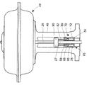
図7は液圧プレス270の形態における液圧アクチュエータ装置の代替的な実施形態を示す。液圧プレス270はアクチュエータ224と制御バルブ(図7において図示せず)との間に配置されたヨーク部240内に装着され得る。液圧プレス270は、固定されるために、アクチュエータ224に代わってヨーク部240に接続され得る。液圧プレス270はステムコネクタまたは位置表示器290にも接続され得る。液圧プレス270は、スロット298およびコネクタ299により、ステムコネクタまたは位置表示器290を、したがってアクチュエータステム225およびバルブステム227を、図7において上下に移動させ得る。液圧プレス270とステムコネクタまたは位置表示器90との間には、他の種類の接続が可能であり、係る接続は当業者の能力の範囲内である。液圧プレス270は視覚的位置目盛Pも含み得、オペレータまたは技師は視覚的位置目盛Pに対するステムコネクタまたは位置表示器290の相対的位置を視覚的に観察することにより制御バルブの位置を判定することができる。液圧プレス270はヨーク部240内において実質的に任意の位置に設置され得、したがって液圧プレス270の位置はそれぞれの特定の制御バルブ組立体に応じて調整され得る。さらに、液圧プレス270は実質的に既知のヨーク部のあらゆる構成に適応され得、したがって既存の制御バルブ組立体の構成に追加設置することができる。
FIG. 7 shows an alternative embodiment of a hydraulic actuator device in the form of a
上述の詳細な説明は理解の明快化のためにのみ与えられたものであり、様々な修正例が当業者には明らかであるため、係る説明を基に不必要な制限を課してはならない。 The foregoing detailed description has been given for clarity of understanding only, and various modifications will be apparent to those skilled in the art, so that no unnecessary limitations should be imposed based on such description. .
Claims (10)
前記バルブプラグを移動させるためのアクチュエータであって、アクチュエータハウジングと、前記アクチュエータハウジング内に装着されたダイヤフラムとを含み、前記ダイヤフラムは前記アクチュエータハウジングを少なくとも2つのチャンバに分割し、アクチュエータステムが、一方端において前記ダイヤフラムに動作可能に接続され、前記ダイヤフラムの移動に応答して往復状に移動し、前記アクチュエータステムは他方端において前記制御バルブステムに接続された、アクチュエータと、
前記制御バルブと前記アクチュエータハウジングとの間に装着された液圧スリーブであって、前記制御バルブステムおよび前記アクチュエータステムのうちの1つに接続され、前記制御バルブステムまたは前記アクチュエータステムのいずれかを前記液圧スリーブ内の変化する液圧に応答して移動させる、液圧スリーブと、
を含む、スライドステムバルブ組立体であって、
前記液圧スリーブは、
スリーブハウジングを形成し、当該スリーブハウジングの内部を画定する外側壁部および内側壁部と、
前記スリーブハウジング内で移動可能に配置され、前記スリーブハウジングの長手方向軸に沿って移動可能である液圧ピストンであって、当該液圧ピストンの第1の端部が、前記スリーブハウジングの前記内部に配置され、当該液圧ピストンの第2の端部が、前記スリーブハウジングの前記内部の外側に配置された液圧ピストンと、
を備え、
前記アクチュエータステムおよび前記制御バルブステムのうちの1つは前記液圧スリーブを貫通し、前記液圧ピストンは前記アクチュエータステム、前記制御バルブステム、および前記アクチュエータステムと前記制御バルブステムとを接続するステムコネクタのうちの1つに取り付けられており、
前記液圧スリーブは、前記アクチュエータハウジングおよび前記制御バルブに対して第1の位置と第2の位置との間で再配置可能であり、前記第1の位置においては、前記ピストンの前記第2の端部は、前記アクチュエータハウジングと前記スリーブハウジングとの間に配置され、前記第2の位置においては、前記ピストンの前記第2の端部は、前記制御バルブと前記スリーブハウジングとの間に配置される、
スライドステムバルブ組立体。 A control valve having a fluid inlet and a fluid outlet, wherein the valve plug is movably positioned between the fluid inlet and the fluid outlet to control the fluid flow through the control valve; The valve plug is connected to a control valve stem, and a control valve;
An actuator for moving the valve plug, comprising an actuator housing and a diaphragm mounted in the actuator housing, wherein the diaphragm divides the actuator housing into at least two chambers, An actuator operatively connected to the diaphragm at one end, reciprocally moving in response to movement of the diaphragm, and the actuator stem connected to the control valve stem at the other end;
A hydraulic sleeve mounted between the control valve and the actuator housing, connected to one of the control valve stem and the actuator stem, wherein either the control valve stem or the actuator stem A hydraulic sleeve that moves in response to changing hydraulic pressure in the hydraulic sleeve;
A slide stem valve assembly comprising :
The hydraulic sleeve is
An outer wall and an inner wall defining a sleeve housing and defining an interior of the sleeve housing;
A hydraulic piston movably disposed within the sleeve housing and movable along a longitudinal axis of the sleeve housing, wherein a first end of the hydraulic piston is located within the interior of the sleeve housing; A hydraulic piston having a second end of the hydraulic piston disposed on the outside of the interior of the sleeve housing;
With
One of the actuator stem and the control valve stem passes through the hydraulic sleeve, and the hydraulic piston connects the actuator stem, the control valve stem, and the actuator stem and the control valve stem. Attached to one of the connectors,
The hydraulic sleeve is repositionable between a first position and a second position with respect to the actuator housing and the control valve, wherein in the first position the second of the piston An end is disposed between the actuator housing and the sleeve housing, and in the second position, the second end of the piston is disposed between the control valve and the sleeve housing. The
Slide stem valve assembly .
液圧スリーブを、制御バルブのアクチュエータステム、制御バルブステム、および前記アクチュエータステムと前記バルブステムとを接続するステムコネクタのうちの1つに取り付けるステップであって、前記液圧スリーブは、スリーブハウジングを形成し、当該スリーブハウジングの内部を画定する外側壁部および内側壁部を含み、かつ前記液圧スリーブは、前記スリーブハウジング内で移動可能に配置され、前記スリーブハウジングの長手方向軸に沿って移動可能である液圧ピストンであって、当該液圧ピストンの第1の端部が、前記スリーブハウジングの前記内部に配置され、当該液圧ピストンの第2の端部が、前記スリーブハウジングの前記内部の外側に配置された液圧ピストンを含み、前記液圧スリーブは、前記アクチュエータハウジングおよび前記制御バルブに対して第1の位置と第2の位置との間で再配置可能であり、前記第1の位置においては、前記ピストンの前記第2の端部は、前記アクチュエータハウジングと前記スリーブハウジングとの間に配置され、前記第2の位置においては、前記ピストンの前記第2の端部は、前記制御バルブと前記スリーブハウジングとの間に配置されるステップと、
前記液圧ピストンを、前記アクチュエータステム、前記制御バルブステム、および前記ステムコネクタのうちの1つに取り付けるステップと、
前記液圧スリーブを作動させることにより前記アクチュエータステムおよび前記制御バルブステムのうちの1つが移動され、それにより前記制御バルブが開放または閉止されるステップと、
を含む方法。 A method of manually operating a slide stem control valve assembly comprising a control valve body and an actuator housing , comprising:
The hydraulic sleeve, the actuator stem of the control valve, the control valve stem, and said method comprising the steps of attaching to one of the stem connector for connecting the actuator stem and the said valve stem, said hydraulic sleeve, the sleeve housing An outer wall and an inner wall defining and defining an interior of the sleeve housing, and the hydraulic sleeve is movably disposed within the sleeve housing and moves along a longitudinal axis of the sleeve housing A hydraulic piston, wherein a first end of the hydraulic piston is disposed in the interior of the sleeve housing, and a second end of the hydraulic piston is disposed in the interior of the sleeve housing. A hydraulic piston disposed on the outside of the actuator, and the hydraulic sleeve includes the actuator housing. Repositioning between a first position and a second position with respect to the ging and the control valve, wherein in the first position the second end of the piston is connected to the actuator housing Disposed between the sleeve housing and, in the second position, the second end of the piston is disposed between the control valve and the sleeve housing;
Attaching the hydraulic piston to one of the actuator stem, the control valve stem, and the stem connector;
Comprising the steps of one of the actuator stem and said control valve stem by operating the fluid pressure sleeve is moved, the control valve is opened or closed by it,
Including methods.
Applications Claiming Priority (1)
| Application Number | Priority Date | Filing Date | Title |
|---|---|---|---|
| PCT/CN2010/080404 WO2012088666A1 (en) | 2010-12-28 | 2010-12-28 | Hydraulic actuating device for a sliding stem control valve assembly |
Publications (3)
| Publication Number | Publication Date |
|---|---|
| JP2014501369A JP2014501369A (en) | 2014-01-20 |
| JP2014501369A5 JP2014501369A5 (en) | 2014-02-27 |
| JP5864605B2 true JP5864605B2 (en) | 2016-02-17 |
Family
ID=46382183
Family Applications (1)
| Application Number | Title | Priority Date | Filing Date |
|---|---|---|---|
| JP2013546548A Active JP5864605B2 (en) | 2010-12-28 | 2010-12-28 | Slide stem control valve assembly and operating method thereof |
Country Status (6)
| Country | Link |
|---|---|
| EP (1) | EP2659170B1 (en) |
| JP (1) | JP5864605B2 (en) |
| CN (1) | CN103403419B (en) |
| BR (1) | BR112013016698B8 (en) |
| CA (1) | CA2823110C (en) |
| WO (1) | WO2012088666A1 (en) |
Families Citing this family (10)
| Publication number | Priority date | Publication date | Assignee | Title |
|---|---|---|---|---|
| DE102012106230A1 (en) | 2012-07-11 | 2014-05-15 | Kraussmaffei Technologies Gmbh | Komponentenzufuhrdüse |
| US9291280B2 (en) * | 2012-07-12 | 2016-03-22 | Fisher Controls International, Llc | Actuator apparatus having internal passageways |
| CN105333158A (en) * | 2015-10-26 | 2016-02-17 | 无锡市圣科不锈钢气动自控阀门厂 | Novel control pneumatic valve |
| CN105729688A (en) * | 2016-04-15 | 2016-07-06 | 金毕顺 | Valve with integrated valve island |
| US10337776B2 (en) * | 2017-09-19 | 2019-07-02 | The Boeing Company | Refrigeration system having valves and valve control actuators |
| WO2019133528A1 (en) * | 2017-12-30 | 2019-07-04 | Itt Manufacturing Enterprises Llc | Switch for diaphragm valve actuator |
| DE102018104209C5 (en) | 2018-02-23 | 2023-11-30 | Hennecke Gmbh | Component mixing nozzle |
| MX2021000372A (en) | 2018-07-12 | 2021-05-27 | Amsted Rail Co Inc | Brake monitoring systems for railcars. |
| CN111424757A (en) * | 2020-04-30 | 2020-07-17 | 山东科源供排水设备工程有限公司 | Hydrodynamic pressure regulation and control pipe network safety device |
| CA3200404A1 (en) * | 2020-11-02 | 2022-05-05 | Amsted Rail Company, Inc. | Sensing method, system and assembly for railway assets |
Family Cites Families (16)
| Publication number | Priority date | Publication date | Assignee | Title |
|---|---|---|---|---|
| US2707483A (en) * | 1950-02-02 | 1955-05-03 | Shafer Valve Co | Pressure fluid operated reclosing type valve |
| US3143143A (en) * | 1960-08-22 | 1964-08-04 | Us Industries Inc | Sequentially operable valves |
| JPS533813B2 (en) | 1973-12-26 | 1978-02-10 | ||
| US4061160A (en) * | 1976-10-08 | 1977-12-06 | Air Products And Chemicals, Inc. | Control valve |
| CH616218A5 (en) * | 1977-02-18 | 1980-03-14 | Lins Albert | Mixing-valve device for cold and hot water |
| CH606880A5 (en) * | 1977-04-22 | 1978-11-15 | Kugler Fonderie Robinetterie | |
| US4445424A (en) * | 1981-10-02 | 1984-05-01 | Baker Cac, Inc. | Actuator having Belleville washer configuration operating in concert with a piston cylinder member |
| JPS6052481U (en) * | 1983-09-20 | 1985-04-12 | 株式会社 フジキン | Diaphragm type regulating valve |
| US4705065A (en) * | 1986-05-16 | 1987-11-10 | Anderson, Greenwood & Company | Safety relief system for control or vent valves |
| WO1994005938A1 (en) * | 1992-09-10 | 1994-03-17 | Nova Scotia Research Foundation Corporation | Manual override system for linear magnetically operated valve |
| US6272401B1 (en) | 1997-07-23 | 2001-08-07 | Dresser Industries, Inc. | Valve positioner system |
| DE10014133A1 (en) * | 1999-03-23 | 2000-11-09 | Fluoroware Inc | Three-way valve |
| GB2388889A (en) * | 2002-05-23 | 2003-11-26 | 4C Group Ltd | A hydraulic diverter valve |
| US8282070B2 (en) * | 2007-09-21 | 2012-10-09 | Fisher Controls International Llc | Apparatus and methods for manual override operation of a linear actuator |
| US8070127B2 (en) * | 2009-02-04 | 2011-12-06 | Fisher Controls International, Llc | Manual override apparatus for linear actuators |
| JP5308921B2 (en) * | 2009-06-01 | 2013-10-09 | 積水化学工業株式会社 | valve |
-
2010
- 2010-12-28 CN CN201080071171.3A patent/CN103403419B/en active Active
- 2010-12-28 BR BR112013016698A patent/BR112013016698B8/en active IP Right Grant
- 2010-12-28 CA CA2823110A patent/CA2823110C/en active Active
- 2010-12-28 EP EP10861344.9A patent/EP2659170B1/en active Active
- 2010-12-28 WO PCT/CN2010/080404 patent/WO2012088666A1/en active Application Filing
- 2010-12-28 JP JP2013546548A patent/JP5864605B2/en active Active
Also Published As
| Publication number | Publication date |
|---|---|
| CA2823110C (en) | 2016-07-19 |
| EP2659170B1 (en) | 2017-09-06 |
| BR112013016698B8 (en) | 2021-10-13 |
| CA2823110A1 (en) | 2012-07-05 |
| EP2659170A1 (en) | 2013-11-06 |
| JP2014501369A (en) | 2014-01-20 |
| BR112013016698B1 (en) | 2021-06-29 |
| CN103403419B (en) | 2016-03-30 |
| WO2012088666A1 (en) | 2012-07-05 |
| EP2659170A4 (en) | 2015-07-22 |
| CN103403419A (en) | 2013-11-20 |
| BR112013016698A2 (en) | 2016-10-04 |
Similar Documents
| Publication | Publication Date | Title |
|---|---|---|
| JP5864605B2 (en) | Slide stem control valve assembly and operating method thereof | |
| US8714515B2 (en) | Hydraulic actuating device for a sliding stem control valve assembly | |
| EP2391842B1 (en) | Actuator having an override apparatus | |
| EP2769100B1 (en) | Volume booster with seat load bias | |
| US9360028B2 (en) | Hydraulic drive and hydraulically operable working tool | |
| CN102822536B (en) | Fluid-actuated actuating drive on valve | |
| EP2492558A1 (en) | Thermo-hydraulically actuated process control valve | |
| KR20160111374A (en) | Valve device for controlling and adjusting fluid passage | |
| CN201705950U (en) | Gas control proportional flow rate valve | |
| US11542964B2 (en) | Arrangements and methods for controlled flow rate of pneumatic actuated valves | |
| US9535428B2 (en) | Spring controlled valve | |
| WO2017123693A1 (en) | Compound loading element for use with electronic adjustment | |
| KR101830165B1 (en) | Actuator for valve | |
| JP2010213931A (en) | Automatic valve device | |
| EP3980857B1 (en) | Actuator for a pilot valve | |
| KR200457222Y1 (en) | Manual override apparatus having an internal hydraulic actuator | |
| CN111963690A (en) | Multifunctional stop valve | |
| CA2996929A1 (en) | Electro-hydraulic valve actuator having modular manifold with configurable redundancy |
Legal Events
| Date | Code | Title | Description |
|---|---|---|---|
| A521 | Request for written amendment filed |
Free format text: JAPANESE INTERMEDIATE CODE: A523 Effective date: 20131225 |
|
| A621 | Written request for application examination |
Free format text: JAPANESE INTERMEDIATE CODE: A621 Effective date: 20131225 |
|
| A977 | Report on retrieval |
Free format text: JAPANESE INTERMEDIATE CODE: A971007 Effective date: 20141024 |
|
| A131 | Notification of reasons for refusal |
Free format text: JAPANESE INTERMEDIATE CODE: A131 Effective date: 20141112 |
|
| A601 | Written request for extension of time |
Free format text: JAPANESE INTERMEDIATE CODE: A601 Effective date: 20150212 |
|
| A601 | Written request for extension of time |
Free format text: JAPANESE INTERMEDIATE CODE: A601 Effective date: 20150311 |
|
| A601 | Written request for extension of time |
Free format text: JAPANESE INTERMEDIATE CODE: A601 Effective date: 20150410 |
|
| A521 | Request for written amendment filed |
Free format text: JAPANESE INTERMEDIATE CODE: A523 Effective date: 20150512 |
|
| TRDD | Decision of grant or rejection written | ||
| A01 | Written decision to grant a patent or to grant a registration (utility model) |
Free format text: JAPANESE INTERMEDIATE CODE: A01 Effective date: 20151125 |
|
| A61 | First payment of annual fees (during grant procedure) |
Free format text: JAPANESE INTERMEDIATE CODE: A61 Effective date: 20151224 |
|
| R150 | Certificate of patent or registration of utility model |
Ref document number: 5864605 Country of ref document: JP Free format text: JAPANESE INTERMEDIATE CODE: R150 |
|
| R250 | Receipt of annual fees |
Free format text: JAPANESE INTERMEDIATE CODE: R250 |
|
| R250 | Receipt of annual fees |
Free format text: JAPANESE INTERMEDIATE CODE: R250 |
|
| R250 | Receipt of annual fees |
Free format text: JAPANESE INTERMEDIATE CODE: R250 |
|
| R250 | Receipt of annual fees |
Free format text: JAPANESE INTERMEDIATE CODE: R250 |
|
| R250 | Receipt of annual fees |
Free format text: JAPANESE INTERMEDIATE CODE: R250 |
|
| R250 | Receipt of annual fees |
Free format text: JAPANESE INTERMEDIATE CODE: R250 |