JP5864458B2 - Game machine - Google Patents
Game machine Download PDFInfo
- Publication number
- JP5864458B2 JP5864458B2 JP2013060831A JP2013060831A JP5864458B2 JP 5864458 B2 JP5864458 B2 JP 5864458B2 JP 2013060831 A JP2013060831 A JP 2013060831A JP 2013060831 A JP2013060831 A JP 2013060831A JP 5864458 B2 JP5864458 B2 JP 5864458B2
- Authority
- JP
- Japan
- Prior art keywords
- replay
- state
- reel
- lip
- combination
- Prior art date
- Legal status (The legal status is an assumption and is not a legal conclusion. Google has not performed a legal analysis and makes no representation as to the accuracy of the status listed.)
- Expired - Fee Related
Links
Images


Description
本発明は、遊技機に関する。 The present invention relates to a gaming machine.
従来、複数の図柄がそれぞれの表面に配された複数のリールと、スタートスイッチと、ストップスイッチと、各リールに対応して設けられたステッピングモータと、制御部とを備えた、パチスロと呼ばれる遊技機が知られている。スタートスイッチは、メダルやコインなどの遊技媒体が遊技機に投入された後、スタートレバーが遊技者により操作されたこと(以下、「開始操作」ともいう)を検出し、全てのリールの回転の開始を要求する信号を出力する。ストップスイッチは、各リールに対応して設けられたストップボタンが遊技者により押されたこと(以下、「停止操作」ともいう)を検出し、該当するリールの回転の停止を要求する信号を出力する。ステッピングモータは、その駆動力を対応するリールに伝達する。また、制御部は、スタートスイッチ及びストップスイッチにより出力された信号に基づいて、ステッピングモータの動作を制御し、各リールの回転動作及び停止動作を行う。 Conventionally, a game called pachislot, comprising a plurality of reels each having a plurality of symbols arranged on each surface, a start switch, a stop switch, a stepping motor provided for each reel, and a control unit. The machine is known. The start switch detects that the start lever has been operated by the player (hereinafter also referred to as “start operation”) after a game medium such as a medal or coin has been inserted into the gaming machine, and the rotation of all reels is detected. Outputs a signal requesting start. The stop switch detects that a stop button provided for each reel has been pressed by the player (hereinafter also referred to as “stop operation”), and outputs a signal requesting the rotation of the corresponding reel to stop. To do. The stepping motor transmits the driving force to the corresponding reel. Further, the control unit controls the operation of the stepping motor based on the signals output from the start switch and the stop switch, and performs the rotation operation and stop operation of each reel.
このような遊技機では、開始操作が検出されると、プログラム上で乱数を用いた抽籤処理(以下、「内部抽籤処理」という)が行われ、その抽籤の結果(以下、「内部当籤役」という)と停止操作のタイミングとに基づいてリールの回転の停止を行う。そして、全てのリールの回転が停止され、入賞の成立に係る図柄の組合せが表示されると、その図柄の組合せに対応する特典が遊技者に付与される。なお、遊技者に付与される特典の例としては、遊技媒体(メダル等)の払い出し、遊技媒体を消費することなく再度、内部抽籤処理を行う再遊技(以下、「リプレイ」ともいう)の作動、遊技媒体の払い出し機会が増加するボーナスゲームの作動等を挙げることができる。 In such a gaming machine, when a start operation is detected, lottery processing using random numbers (hereinafter referred to as “internal lottery processing”) is performed on the program, and the result of the lottery (hereinafter referred to as “internal winning combination”). And the rotation of the reel is stopped based on the timing of the stop operation. Then, when the rotation of all the reels is stopped and the symbol combination related to the winning is displayed, a privilege corresponding to the symbol combination is given to the player. As an example of a privilege granted to a player, a replay (hereinafter also referred to as “replay”) in which an internal lottery process is performed again without paying out game media (medals, etc.) or consuming the game media. An operation of a bonus game in which a game medium payout opportunity increases can be cited.
また、従来、上記構成の遊技機において、ボーナス図柄と称される図柄と同一又は類似の形状を有し、かつ、該ボーナス図柄とは異なる色彩を有する図柄により構成される図柄組合せが停止表示された場合に、所定の期間に渡って高確率でリプレイが当籤する遊技状態(高RT状態)を発生させる遊技機が知られている(例えば、特許文献1参照)。具体的には、特許文献1の遊技機において、入賞判定ライン上に「特殊リプレイ」と称される役に係る図柄組合せ「青7」−「青7」−「青7」(「青7」は各リールに設けられた図柄)が停止表示されると、高RT状態(RT2作動状態)が発生する。
Conventionally, in the gaming machine having the above-described configuration, a symbol combination composed of symbols having the same or similar shape as the symbol called bonus symbol and having a color different from the bonus symbol is stopped and displayed. In such a case, a gaming machine is known that generates a gaming state (high RT state) in which replay is won with high probability over a predetermined period (see, for example, Patent Document 1). Specifically, in the gaming machine of
上述のように、従来、特定の条件が成立したときに高RT状態を発生させる遊技機が知られているが、近年では、このような遊技機において、高RT状態中にメダル付与に関する停止操作の情報(遊技を有利にする情報)をランプ等で報知する、アシストタイム(以下、「AT」という)と呼ばれる機能を備える遊技機が主流になっている。すなわち、RT機能とAT機能とが同時に作動するアシストリプレイタイム(以下、「ART」という)の機能を備えた遊技機が知られている。 As described above, conventionally, a gaming machine that generates a high RT state when a specific condition is satisfied is known. In recent years, in such a gaming machine, a stop operation related to medal granting during a high RT state is known. Game machines having a function called assist time (hereinafter referred to as “AT”) that informs the above information (information that makes the game advantageous) with a lamp or the like have become mainstream. That is, a gaming machine having a function of assist replay time (hereinafter referred to as “ART”) in which the RT function and the AT function are simultaneously operated is known.
このようなART機能を備える遊技機において、ARTの作動開始条件として、上記特許文献1で提案されている高RT状態の作動開始条件(「特殊リプレイ」に係る図柄組合せの停止表示)を適用した場合、「特殊リプレイ」が内部当籤した状態であっても「特殊リプレイ」に係る図柄組合せを停止表示させることができなければARTを作動開始させることができない。このような遊技機において、目押しが不慣れな遊技者がARTを作動させることは困難であり、このようなARTの開始条件は、目押しに不慣れな遊技者の遊技意欲を衰退させる原因になり得る。 In a gaming machine having such an ART function, the operation start condition in the high RT state proposed in Patent Document 1 (the symbol combination stop display related to “special replay”) is applied as the ART operation start condition. In this case, even if the “special replay” is in the state of being won internally, the ART cannot be started unless the symbol combination related to the “special replay” can be stopped and displayed. In such a gaming machine, it is difficult for a player who is unfamiliar with the push to operate the ART, and such an ART start condition causes a decline in the game motivation of a player who is unfamiliar with the push. obtain.
それゆえ、目押しが必要となる遊技機では、目押しが不慣れな遊技者の損失が大きくなるので、遊技者の遊技離れが発生する可能性がある。その結果、遊技機の稼働低下が発生し、遊技店に損失を与える恐れがある。 Therefore, in a gaming machine that requires pressing, the loss of the player who is unfamiliar with pressing increases, and there is a possibility that the player will leave the game. As a result, the operation of the gaming machine is reduced, which may cause a loss to the gaming store.
本発明は、上記問題を解決するためになされたものであり、本発明の目的は、目押しに不慣れな遊技者であっても安心して遊技が行える遊技機を提供することである。 The present invention has been made to solve the above problems, and an object of the present invention is to provide a gaming machine that allows a player who is unfamiliar with the game to play a game with peace of mind.
上記課題を解決するために、本発明では、以下のような構成の遊技機を提供する。 In order to solve the above problems, the present invention provides a gaming machine having the following configuration.
遊技媒体の投入操作を検出する投入操作検出手段(例えば、後述のメダルセンサ35S)と、
前記投入操作検出手段による投入操作の検出に基づいて遊技者による開始操作を検出する開始操作検出手段(例えば、後述のスタートスイッチ16S)と、
前記開始操作検出手段による開始操作の検出に基づいて予め定められた確率で内部当籤役を決定する内部当籤役決定手段(例えば、後述の内部抽籤処理)と、
複数の表示列によって構成され、前記開始操作検出手段による開始操作の検出に基づいて、遊技に必要な図柄を変動表示する変動表示手段(例えば、後述の3つのリール3L,3C,3R及び3つのステッピングモータ61L,61C,61R)と、
遊技者による停止操作の検出を行う停止操作検出手段(例えば、後述のストップスイッチ17S)と、
前記内部当籤役決定手段の決定結果と前記停止操作検出手段による停止操作の検出とに基づいて、前記図柄の変動表示を停止させる停止制御手段(例えば、後述のリール停止制御処理)と、
遊技者にとって有利な状態を与える図柄の組合せを前記複数の表示列に跨る判定ライン上に表示するための情報を報知する報知手段(例えば、後述の表示装置10)と、
所定の図柄の組合せが前記判定ライン上に表示された場合に、前記内部当籤役決定手段により再遊技に係る内部当籤役を決定する確率がより高くなるリプレイタイム状態に移行させる制御を行うリプレイタイム状態制御手段(例えば、後述のRT制御処理)と、
特定の条件が成立した単位遊技の次の単位遊技の開始時に行われる前記変動表示手段の加速処理の期間において、前記複数の表示列に跨る特定のライン上に、特定の図柄の組合せを表示する演出(例えば、後述の図柄表示演出)を行う表示列演出手段(後述の遊技開始時制御処理)と、
前記加速処理の期間において、前記表示列演出手段による前記演出の後に、前記複数の表示列をランダムに加速するランダム加速手段(例えば、後述のランダム加速処理)と、を備え、
前記報知手段による報知が行われる遊技状態及び前記リプレイタイム状態が同時に発生する特別な遊技状態(例えば、後述の「ART状態」)へ移行する確率が通常遊技状態より高い特別遊技準備状態(例えば、後述の「擬似BBフラグ間」又は「擬似RBフラグ間」)において、特別な図柄の組合せ(例えば、後述の「赤7揃い」又は「RB揃い」の図柄組合せ)を含む、遊技状態を前記特別な遊技状態に移行させるための図柄の組合せを前記停止制御手段により前記判定ライン上に停止表示できずに、遊技状態が前記特別遊技準備状態から前記通常遊技状態に移行した場合には、
前記報知手段は、前記通常遊技状態において、前記特別な図柄の組合せ以外の図柄の組合せであり、かつ、遊技状態を前記特別な遊技状態に移行させることが可能な図柄の組合せ(例えば後述の「リプレイ4」に係る図柄組合せ)を前記判定ライン上に停止表示させるための前記複数の表示列の変動表示に対する停止順序を報知し、
前記報知手段による前記複数の表示列の変動表示に対する停止順序の報知に従って、前記停止制御手段により前記特別な図柄の組合せ以外の図柄の組合せが前記判定ライン上に停止表示され、遊技状態が前記特別な遊技状態(例えば、後述の「ART状態」(「擬似ボーナス救済状態」))に移行した場合には、
前記表示列演出手段は、前記特別な遊技状態への移行が確定した単位遊技の次の単位遊技の前記加速処理の期間において、遊技状態が前記通常遊技状態に移行する前の前記特別遊技準備状態に関する情報(後述のフラグ間移行時判別子)に基づいて、該情報に対応する前記特別な図柄の組合せを前記複数の表示列に跨る特定のライン上に表示する演出(例えば、後述の「擬似ボーナス入賞見せかけ演出」)を行う
ことを特徴とする遊技機。
A loading operation detecting means (for example, a
Start operation detecting means (for example, a
Internal winning combination determining means (for example, internal lottery processing described later) for determining an internal winning combination with a predetermined probability based on detection of the start operation by the start operation detecting means;
Based on the detection of the start operation by the start operation detecting means, the variable display means (for example, three
A stop operation detecting means (for example, a
Stop control means (for example, reel stop control process described later) for stopping the change display of the symbol based on the determination result of the internal winning combination determining means and detection of the stop operation by the stop operation detecting means;
A notification means (for example, a
When a predetermined symbol combination is displayed on the determination line, the replay time for performing control to shift to the replay time state in which the probability of determining the internal winning combination relating to replay is higher by the internal winning combination determining means State control means (for example, RT control processing described later);
A combination of specific symbols is displayed on a specific line across the plurality of display columns in a period of acceleration processing of the variable display means performed at the start of a unit game next to a unit game that satisfies a specific condition. Display row effect means (for example, a game start time control process described later) for performing effects (for example, a symbol display effect described later);
Random acceleration means (for example, random acceleration processing described later) for randomly accelerating the plurality of display rows after the presentation by the display row presentation means in the period of the acceleration processing,
A special game preparation state (e.g., a higher probability of transition to a special game state (e.g., an "ART state" described later) in which the game state notified by the notification means and the replay time state occur simultaneously) In the “between pseudo BB flag” or “between pseudo RB flag” described later), the gaming state including a special symbol combination (for example, “red 7 uniform” or “RB uniform” described later) is included in the special game state. When a combination of symbols for shifting to a different gaming state cannot be stopped and displayed on the determination line by the stop control means, and the gaming state shifts from the special gaming preparation state to the normal gaming state,
The notifying means is a combination of symbols other than the special symbol combination in the normal gaming state, and a combination of symbols that can shift the gaming state to the special gaming state (for example, “ Informing the stop order for the variable display of the plurality of display columns for stopping and displaying the symbol combination) related to “
In accordance with the notification of the stop order for the variable display of the plurality of display columns by the notification means, the stop control means stops and displays a combination of symbols other than the special symbol combination on the determination line, and the gaming state is the special state. When the game state is changed to a game state (for example, “ART state” described later (“pseudo bonus relief state”)),
The display row effect means is the special game preparation state before the game state shifts to the normal game state in the acceleration processing period of the unit game next to the unit game for which the transition to the special game state is confirmed. Based on the information (discriminator at the time of transition between flags to be described later), an effect of displaying the special symbol combination corresponding to the information on a specific line across the plurality of display columns (for example, “pseudo” described later) A gaming machine characterized by performing a bonus prize appearance.
また、前記本発明の遊技機では、前記表示列演出手段は、前記特定の図柄の組合せを前記特定のライン上に表示する演出を行う前に、各表示列を所定のパターンで回転動作させる演出(例えば、後述のリールアクション演出)を行うようにしてもよい。 Further, in the gaming machine of the present invention, the display row effect means rotates the display rows in a predetermined pattern before performing the effect of displaying the specific symbol combination on the specific line. (For example, a reel action effect described later) may be performed.
本発明では、特別な遊技状態(ART状態)に移行させるための特別な図柄の組合せが停止表示できなかった場合であっても、特別な図柄の組合せ以外の図柄の組合せを停止表示して遊技状態を特別な遊技状態に移行させ、特別な遊技状態に移行した後の最初の単位遊技の加速処理において、特別な図柄の組合せを表示する演出を行う。 In the present invention, even if a special symbol combination for shifting to a special gaming state (ART state) cannot be stopped and displayed, a combination of symbols other than the special symbol combination is stopped and displayed. The state is shifted to a special game state, and in the first unit game acceleration process after the shift to the special game state, an effect of displaying a special symbol combination is performed.
すなわち、本発明の遊技機では、目押しが不慣れな遊技者であっても、特典(ART)が付与され易く(損し難く)、また、リール演出によって特典が付与されたことを遊技者が容易に把握することができる。それゆえ、本発明によれば、目押しが不慣れな遊技者であっても、安心して遊技を行うことができる。 In other words, in the gaming machine of the present invention, even if the player is unfamiliar with the appearance, a privilege (ART) is easily given (hard to lose), and the player can easily understand that the privilege is given by the reel production. Can grasp. Therefore, according to the present invention, even a player who is unaccustomed to seeing can play a game with peace of mind.
以下では、本発明に係る遊技機の一実施形態を示すパチスロについて、図面を参照しながら説明する。なお、本実施形態ではART(擬似ボーナス)の機能を備えたパチスロについて説明する。 Hereinafter, a pachi-slot showing an embodiment of a gaming machine according to the present invention will be described with reference to the drawings. In the present embodiment, a pachislot having an ART (pseudo bonus) function will be described.
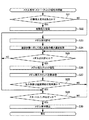
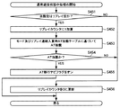
<機能フロー>
まず、図1を参照して、パチスロの機能フローについて説明する。本実施形態のパチスロでは、遊技を行うための遊技媒体としてメダルを用いる。なお、遊技媒体としては、メダル以外にも、例えば、コイン、遊技球、遊技用のポイントデータ又はトークン等を適用することもできる。
<Function flow>
First, the functional flow of the pachislot will be described with reference to FIG. In the pachislot machine of this embodiment, medals are used as game media for playing games. In addition to medals, for example, coins, game balls, game point data, tokens, or the like can be applied as game media.
遊技者によりパチスロにメダルが投入され、スタートレバーが操作されると、予め定められた数値の範囲(例えば、0〜65535)の乱数から1つの値(以下、乱数値)が抽出される。 When a player inserts a medal into the pachislot and operates the start lever, one value (hereinafter, random number value) is extracted from random numbers in a predetermined numerical range (for example, 0 to 65535).
内部抽籤手段は、抽出された乱数値に基づいて抽籤を行い、内部当籤役を決定する。内部当籤役の決定により、後述の有効ライン(入賞判定ライン)に沿って表示を行うことを許可する図柄の組合せが決定される。なお、図柄の組合せの種別としては、メダルの払い出し、リプレイ(再遊技)の作動等といった特典が遊技者に与えられる「入賞」に係るものと、それ以外のいわゆる「ハズレ」に係るものとが設けられる。 The internal lottery means performs lottery based on the extracted random number value and determines an internal winning combination. By determining the internal winning combination, a combination of symbols that permits display along an after-mentioned effective line (winning determination line) is determined. Note that the types of symbol combinations include those related to “winning” in which benefits such as paying out medals, operation of replay (replay), etc. are given to the player, and those relating to other so-called “losing”. Provided.
また、スタートレバーが操作されると、複数のリールの回転が行われる。その後、遊技者により所定のリールに対応するストップボタンが押されると、リール停止制御手段及び特別遊技停止制御手段は、内部当籤役とストップボタンが押されたタイミングとに基づいて、該当するリールの回転を停止する制御を行う。 Further, when the start lever is operated, a plurality of reels are rotated. After that, when the player presses the stop button corresponding to the predetermined reel, the reel stop control means and the special game stop control means, based on the internal winning combination and the timing when the stop button is pressed, Control to stop rotation.
パチスロでは、基本的に、ストップボタンが押されたときから規定時間(190msec)内に、該当するリールの回転を停止する制御が行われる。本実施形態では、この規定時間内にリールの回転に伴って移動する図柄の数を「滑り駒数」と呼び、その最大数を図柄4個分に定める。 In the pachi-slot, basically, control for stopping the rotation of the corresponding reel is performed within a specified time (190 msec) from when the stop button is pressed. In the present embodiment, the number of symbols that move with the rotation of the reel within the specified time is referred to as “the number of sliding symbols”, and the maximum number is determined as four symbols.
リール停止制御手段は、入賞に係る図柄の組合せ表示を許可する内部当籤役が決定されているときは、190msec(図柄4コマ分)の規定時間内に、その図柄の組合せが有効ラインに沿って極力表示されるようにリールの回転を停止させる。また、リール停止制御手段は、規定時間を利用して、内部当籤役によってその表示が許可されていない図柄の組合せが有効ラインに沿って表示されないようにリールの回転を停止させる。 The reel stop control means, when an internal winning combination permitting the symbol combination display related to winning is determined, within a specified time of 190 msec (for 4 symbols), the symbol combination follows the active line. Stop reel rotation to display as much as possible. In addition, the reel stop control means stops the rotation of the reel using a specified time so that the combination of symbols that are not permitted to be displayed by the internal winning combination is not displayed along the active line.
このようにして、複数のリールの回転がすべて停止されると、入賞判定手段は、有効ラインに沿って表示された図柄の組合せが、入賞に係るものであるか否かの判定を行う。入賞判定手段により入賞に係る図柄の組合せであるとの判定が行われると、メダルの払い出し等の特典が遊技者に与えられる。パチスロでは、以上のような一連の流れの動作が1回の遊技(単位遊技)として行われる。 In this way, when all the rotations of the plurality of reels are stopped, the winning determination means determines whether or not the combination of symbols displayed along the active line relates to winning. When the winning determination means determines that the symbol combination is related to winning, a bonus such as a medal payout is given to the player. In the pachislot, the above-described series of operations are performed as a single game (unit game).
なお、パチスロでは、前述した一連の動作の中で、表示装置により行う映像の表示、各種ランプにより行う光の出力、スピーカにより行う音の出力、又は、これらの組合せを利用して様々な演出が行われる。さらに、本実施形態では、例えば、後述するようにARTの遊技開始時のリールの加速期間において、ARTの入賞等を報知するための各種リール演出も行う。 In the pachislot, in the series of operations described above, various effects can be achieved by using the display of video performed by the display device, the output of light by various lamps, the output of sound by the speaker, or a combination thereof. Done. Further, in the present embodiment, for example, various reel effects for notifying an ART winning or the like are performed in the acceleration period of the reel at the start of the ART game, as will be described later.
また、パチスロでは、スタートレバーが操作されると、上述した内部当籤役の決定に用いられた乱数値とは別に、演出用の乱数値(以下、演出用乱数値)が抽出される。演出用乱数値が抽出されると、演出内容決定手段は、内部当籤役に対応づけられた複数種類の演出内容の中から今回実行する演出内容を抽籤により決定する。 Further, in the pachislot, when the start lever is operated, a random number value for production (hereinafter referred to as a production random number value) is extracted separately from the random value used for determining the internal winning combination described above. When the effect random number is extracted, the effect content determining means determines the effect content to be executed this time from among a plurality of types of effect contents associated with the internal winning combination.
演出内容が決定されると、演出実行手段は、例えば、リールの回転開始時、各リールの回転停止時、入賞の有無の判定時等の各契機に連動させて対応する演出を実行する。このように、パチスロでは、内部当籤役に対応づけられた演出内容を実行することによって、決定された内部当籤役(言い換えると、遊技者が狙うべき図柄の組合せ)を知る機会又は予想する機会が遊技者に提供され、遊技者の興味の向上を図ることができる。 When the content of the effect is determined, the effect execution means executes the corresponding effect in conjunction with each opportunity, for example, at the start of reel rotation, when the rotation of each reel is stopped, or when determining whether or not there is a prize. In this way, in the pachislot, the opportunity to know or predict the determined internal winning combination (in other words, the combination of symbols to be aimed by the player) by executing the production contents associated with the internal winning combination. It is provided to the player and the player's interest can be improved.
<パチスロの構造>
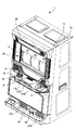
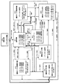
次に、図2及び図3を参照して、本実施形態におけるパチスロの構造について説明する。なお、図2は、本実施形態のパチスロ1の外部構造を示す斜視図であり、図3は、パチスロ1の内部構造を示す図である。
<Pachislot structure>
Next, the structure of the pachislot machine according to the present embodiment will be described with reference to FIGS. 2 is a perspective view showing an external structure of the
[外観構造]
パチスロ1は、図2に示すように、リールや回路基板等を収容したキャビネット1aと、キャビネット1aに対して開閉可能に取り付けられたフロントドア1bとを備える。キャビネット1aの内部には、3つのリール3L,3C,3R(変動表示手段)が設けられ、該3つのリール3L,3C,3Rは横方向(リールの回転方向と直交する方向)に一列に配置される。以下、リール3L,3C,3Rを、それぞれ左リール3L、中リール3C、右リール3Rという。
[Appearance structure]
As shown in FIG. 2, the pachi-
各リール(表示列)は、円筒状のリール本体と、リール本体の周面(周回面)に装着された透光性のシート材とを有する。シート材の表面には、複数(例えば21個)の図柄がリール本体の周方向に沿って連続的に描かれる。 Each reel (display row) has a cylindrical reel body and a translucent sheet material mounted on the peripheral surface (circumferential surface) of the reel body. A plurality of (for example, 21) symbols are continuously drawn on the surface of the sheet material along the circumferential direction of the reel body.
フロントドア1bの中央には、表示装置10(報知手段)が設けられる。そして、表示装置10は、3つのリール3L,3C,3Rに描かれた図柄を表示する表示窓4を含む表示画面を備える。本実施形態では、表示窓4を含む表示画面の全体を使って演出が実行される。
A display device 10 (notification means) is provided in the center of the
本実施形態では、表示窓4の上部に設けられた表示部は、マトリックス状に配置された複数のLED(Light Emitting Diode)で構成される。そして、この表示部では、複数のLEDの点消灯により表されるドットパターンにより、演出(報知)が行われる。なお、本発明はこれに限定されず、表示窓4の上部に設けられた表示部が液晶表示装置で構成されていてもよい。
In this embodiment, the display part provided in the upper part of the
表示窓4は、例えばアクリル板等の透明部材で構成され、図2に示すように、正面(遊技者側)から見て、3つのリールの配置領域と重畳する位置に設けられ、かつ、3つのリールより手前(遊技者側)に位置するように設けられる。それゆえ、表示窓4の背後に設けられた3つのリールに描かれた図柄が、表示窓4を介して目視することができる。
The
本実施形態では、表示窓4は、その背後に設けられた対応するリールの回転が停止したとき、各リールに描かれた複数種類の図柄のうち、連続して配置された3つの図柄を表示できるように構成される。すなわち、表示窓4の枠内には、リール毎に上段、中段及び下段の各領域が設けられ、各領域に1個の図柄を表示することができる。そえゆえ、本実施形態では、表示窓4の枠内に、3×3の配列形態で図柄が表示される。そして、本実施形態では、左リール3Lの中段領域、中リール3Cの中段領域、及び、右リール3Rの中段領域を結ぶライン(センターライン)を、入賞か否かの判定を行うライン(以下、有効ラインという)として定義する。
In the present embodiment, when the rotation of the corresponding reel provided behind the
また、表示装置10の表示画面の下部には、7セグメントLEDからなる7セグ表示器6が設けられる。7セグ表示器6は、今回の遊技に投入されたメダルの枚数(以下、投入枚数という)、特典として遊技者に払い出されるメダルの枚数(以下、払出枚数という)、パチスロ1の内部に預けられているメダルの枚数(以下、クレジット枚数という)等の情報をデジタル表示する。
In addition, a 7-
また、フロントドア1bには、遊技者の操作対象となる各種装置(メダル投入口11、MAXベットボタン12、1BETボタン14、スタートレバー16、ストップボタン17L,17C,17R)が設けられる。
Further, the
メダル投入口11は、遊技者によって外部からパチスロ1に投入されるメダルを受け入れるために設けられる。メダル投入口11を介して受け入れられたメダルは、所定枚数(例えば3枚)を上限として1回の遊技に投入され、所定枚数を超えた分は、パチスロ1の内部に預けることができる(いわゆるクレジット機能)。なお、本実施形態のパチスロ1では、1回の遊技に投入可能なメダルの枚数は、3枚とする。
The
MAXベットボタン12及び1BETボタン14は、パチスロ1の内部に預けられているメダルから1回の遊技に投入する枚数を決定するために設けられる。なお、図2には示さないが、フロントドア1bには、精算ボタンが設けられる(スタートレバー16のストップボタン側とは反対側の側部に配置されている)。この精算ボタンは、パチスロ1の内部に預けられているメダルを外部に引き出す(排出する)ために設けられる。
The
スタートレバー16は、全てのリール(3L,3C,3R)の回転を開始するために設けられる。ストップボタン17L,17C,17Rは、それぞれ、左リール3L、中リール3C、右リール3Rに対応づけて設けられ、各ストップボタンは対応するリールの回転を停止するために設けられる。以下、ストップボタン17L,17C,17Rを、それぞれ左ストップボタン17L、中ストップボタン17C、右ストップボタン17Rという。
The
さらに、フロントドア1bには、図2に示すように、メダル払出口18、メダル受皿19、スピーカ21L,21R等が設けられる。また、フロントドア1bには、ランプ20等が設けられる。
Further, as shown in FIG. 2, the
メダル払出口18は、後述のメダル払出装置33の駆動により排出されるメダルを外部に導く。メダル受皿19は、メダル払出口18から排出されたメダルを貯める。また、フロントドア1bに設けられたランプ20は、LED等で構成され、演出内容に対応するパターンで、光を点消灯する。また、スピーカ21L,21Rは、演出内容に対応する効果音や楽曲等の音を出力する。
The
[内部構造]
次に、パチスロ1の内部構造を、図3を参照しながら説明する。なお、図3は、フロントドア1bが開放された状態を示す図であり、フロントドア1bの裏面側の構造及びキャビネット1aの内部の構造を示す。
[Internal structure]
Next, the internal structure of the
キャビネット1a内の上方部分には、後述の主制御回路41(後述の図4参照)を構成する主基板31が設けられる。主制御回路41は、内部当籤役の決定、各リールの回転及び停止、入賞の有無の判定等の、パチスロ1における遊技の主な動作及び該動作間の流れを制御する回路である。なお、主制御回路41の具体的な構成は後述する。
A
キャビネット1a内の中央部分には、3つのリール(左リール3L、中リール3C及び右リール3R)が設けられる。なお、図3には示さないが、各リールは、所定の減速比を有するギアを介して対応する後述のステッピングモータ(後述の図4中のステッピングモータ61L,61C,61Rのいずれか)に接続される。
Three reels (a
キャビネット1a内の下方部分には、多量のメダルを収容可能であり、かつ、それらを1枚ずつ排出可能な構造を有するメダル払出装置33(以下、ホッパー33という)が設けられる。また、キャビネット1a内における、ホッパー33の一方の側部(図3に示す例では左側)には、パチスロ1が有する各装置に対して必要な電力を供給する電源装置34が設けられる。
A lower portion in the cabinet 1a is provided with a medal payout device 33 (hereinafter referred to as a hopper 33) that can accommodate a large amount of medals and can discharge them one by one. In addition, a
フロントドア1bの裏側部(表示画面側とは反対側の部分)において、表示窓4の配置領域の上方部分には、後述の副制御回路42(後述の図4及び図5参照)を構成する副基板32が設けられる。副制御回路42は、映像の表示等による演出の実行を制御する回路である。なお、副制御回路42の具体的な構成は後述する。
On the back side of the
さらに、フロントドア1bの裏側部において、表示窓4の配置領域の下方部分には、セレクタ35が設けられる。セレクタ35は、メダル投入口11を介して外部から投入されたメダルの材質や形状等が適正である否かを選別する装置であり、適正であると判定されたメダルをホッパー33に案内する。また、図3には示さないが、セレクタ35内においてメダルが通過する経路上には、適正なメダルが通過したことを検出するメダルセンサ35S(後述の図4参照)が設けられる。
Further, a
<パチスロが備える回路の構成>
次に、図4及び図5を参照して、本実施形態におけるパチスロ1が備える回路の構成について説明する。なお、図4は、パチスロ1が備える回路全体のブロック構成図であり、図5は、副制御回路の内部構成を示すブロック構成図である。
<Configuration of circuits provided in pachislot>
Next, with reference to FIG.4 and FIG.5, the structure of the circuit with which the
パチスロ1は、図4に示すように、主制御回路41、副制御回路42、及び、これらの回路と電気的に接続される周辺装置(アクチュエータ)を備える。
As shown in FIG. 4, the pachi-
[主制御回路]
主制御回路41は、主に、回路基板(主基板31)上に設置されたマイクロコンピュータ50により構成される。それ以外の構成要素として、主制御回路41は、図4に示すように、クロックパルス発生回路54、分周器55、乱数発生器56、サンプリング回路57、表示部駆動回路64、ホッパー駆動回路65、及び、払出完了信号回路66を含む。
[Main control circuit]
The
マイクロコンピュータ50は、メインCPU51、メインROM(Read Only Memory)52及びメインRAM(Random Access Memory)53により構成される。
The
メインROM52には、メインCPU51により実行される各種処理(後述の図87〜図112参照)の制御プログラム、内部抽籤テーブル等のデータテーブル(後述の図6〜図59等参照)、副制御回路42に対して各種制御指令(コマンド)を送信するためのデータ等が記憶される。メインRAM53には、制御プログラムの実行により決定された内部当籤役等の各種データを格納する格納領域(図60〜図66参照)が設けられる。
The
メインCPU51には、図4に示すように、クロックパルス発生回路54、分周器55、乱数発生器56及びサンプリング回路57が接続される。クロックパルス発生回路54及び分周器55は、クロックパルスを発生する。なお、メインCPU51は、発生されたクロックパルスに基づいて、制御プログラムを実行する。また、乱数発生器56は、予め定められた範囲の乱数(例えば、0〜65535)を発生する。そして、サンプリング回路57は、発生された乱数の中から1つの値を抽出する。
As shown in FIG. 4, a clock
マイクロコンピュータ50の入力ポートには、各種スイッチ及びセンサ等が接続される。メインCPU51は、各種スイッチ等からの入力信号を受けて、ステッピングモータ61L,61C,61R等の周辺装置の動作を制御する。
Various switches and sensors are connected to the input port of the
ストップスイッチ17S(停止操作検出手段)は、左ストップボタン17L、中ストップボタン17C、右ストップボタン17Rのそれぞれが遊技者により押されたこと(停止操作)を検出する。スタートスイッチ16S(開始操作検出手段)は、スタートレバー16が遊技者により操作されたこと(開始操作)を検出する。精算スイッチ14Sは、精算ボタンが遊技者により押されたことを検出する。
The
メダルセンサ35S(投入操作検出手段)は、メダル投入口11に投入されたメダルがセレクタ35内を通過したことを検出する。また、ベットスイッチ12Sは、ベットボタン(MAXベットボタン12又は1BETボタン14)が遊技者により押されたことを検出する。
The
また、マイクロコンピュータ50により動作が制御される周辺装置としては、3つのステッピングモータ61L,61C,61R(変動表示手段)、7セグ表示器6及びホッパー33がある。また、マイクロコンピュータ50の出力ポートには、各周辺装置の動作を制御するための駆動回路が接続される。
Peripheral devices whose operations are controlled by the
モータ駆動回路62は、左リール3L、中リール3C、右リール3Rに対応してそれぞれ設けられた3つのステッピングモータ61L,61C,61Rの駆動を制御する。リール位置検出回路63は、発光部と受光部とを有する光センサにより、リールが一回転したことを示すリールインデックスをリール毎に検出する。
The
3つのステッピングモータ61L,61C,61Rのそれぞれは、その運動量がパルスの出力数に比例し、回転軸を指定された角度で停止させることが可能な構成を有する。また、各ステッピングモータの駆動力は、所定の減速比を有するギアを介して、対応するリールに伝達される。そして、各ステッピングモータに対して1回のパルスが出力されるごとに、対応するリールは一定の角度で回転する。
Each of the three
メインCPU51は、各リールのリールインデックスを検出してから対応するステッピングモータに対してパルスが出力された回数をカウントすることによって、各リールの回転角度(具体的には、リールが図柄何個分だけ回転したか)を管理する。
The
ここで、各リールの回転角度の管理を具体的に説明する。各ステッピングモータに対して出力されたパルスの数は、メインRAM53に設けられたパルスカウンタ(不図示)によって計数される。そして、図柄1個分の回転に必要な所定回数(例えば16回)のパルスの出力がパルスカウンタで計数されるごとに、メインRAM53に設けられた図柄カウンタ(不図示)の値に、「1」が加算される。なお、図柄カウンタは、リール毎に設けられる。そして、図柄カウンタの値は、リール位置検出回路63によってリールインデックスが検出されるとクリアされる。
Here, the management of the rotation angle of each reel will be specifically described. The number of pulses output to each stepping motor is counted by a pulse counter (not shown) provided in the
すなわち、本実施形態では、図柄カウンタの値を管理することにより、リールインデックスが検出されてから図柄何個分の回転動作が行われたのかを管理する。それゆえ、各リールの各図柄の位置は、リールインデックスが検出される位置を基準として検出される。なお、本実施形態では、上述のように、滑り駒数の最大数を図柄4個分に定めるので、例えば、遊技中に所定のリールに対応するストップボタンが押されたときには、表示窓4内の入賞判定ライン上の対応する領域に位置する所定のリールの図柄と、その4個先までの範囲に存在する図柄が、該領域に停止可能な図柄となる。なお、後述する各種リール演出において特定の図柄組合せを停止表示する場合にも、前述した手法と同様にして、各リールに対してリールインデックスを検出し、該検出結果に基づいて、特定の図柄を停止させる。 In other words, in the present embodiment, by managing the value of the symbol counter, it is managed how many symbols have been rotated since the reel index was detected. Therefore, the position of each symbol on each reel is detected with reference to the position where the reel index is detected. In the present embodiment, as described above, the maximum number of sliding symbols is set to 4 symbols. For example, when a stop button corresponding to a predetermined reel is pressed during a game, the display window 4 A symbol of a predetermined reel located in a corresponding area on the winning determination line and a symbol existing in a range of up to four reels are symbols that can be stopped in the area. Even when a specific symbol combination is stopped and displayed in various reel effects described later, a reel index is detected for each reel in the same manner as described above, and a specific symbol is detected based on the detection result. Stop.
また、主制御回路41に含まれる、表示部駆動回路64は、7セグ表示器6の動作を制御する。ホッパー駆動回路65は、ホッパー33の動作を制御する。払出完了信号回路66は、ホッパー33に設けられたメダル検出部33Sが行うメダルの検出を管理し、ホッパー33から外部に排出されたメダルが所定の払出枚数に達したか否かをチェックする。
Further, the display
[副制御回路]
副制御回路42は、図4及び図5に示すように、主制御回路41に接続され、主制御回路41から送信されるコマンドに基づいて演出内容の決定や実行等の処理を行う。副制御回路42は、基本的には、図5に示すように、サブCPU81、サブROM82、サブRAM83、レンダリングプロセッサ84、描画用RAM85、ドライバ86、DSP(Digital Signal Processor)90、オーディオRAM91、A/D(Analog to Digital)変換器92、及び、アンプ93を含む。
[Sub control circuit]
As shown in FIGS. 4 and 5, the
サブCPU81は、主制御回路41から送信されたコマンドに応じて、サブROM82に記憶されている制御プログラムに従い、映像、音、光の出力制御を行う。なお、サブROM82は、基本的には、プログラム記憶領域及びデータ記憶領域を有する。
The
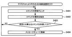
プログラム記憶領域には、サブCPU81が実行する各種制御プログラムが記憶される。なお、プログラム記憶領域に格納される制御プログラムには、例えば、主制御回路41との通信を制御するための主基板通信タスク、演出用乱数値を抽出して演出内容(演出データ)の決定及び登録を行うための演出登録タスク、決定した演出内容に基づいて表示装置10による映像の表示を制御するための描画制御タスク、ランプ20による光の出力を制御するためのランプ制御タスク、スピーカ21L,21Rによる音の出力を制御するための音声制御タスク等のプログラムが含まれる。
Various control programs executed by the
データ記憶領域には、例えば、各種データテーブルを記憶する記憶領域、各種演出内容を構成する演出データを記憶する記憶領域、映像の作成に関するアニメーションデータを記憶する記憶領域、BGMや効果音に関するサウンドデータを記憶する記憶領域、光の点消灯のパターンに関するランプデータを記憶する記憶領域等の各種記憶領域が含まれる。 In the data storage area, for example, a storage area for storing various data tables, a storage area for storing effect data constituting various effects, a storage area for storing animation data relating to creation of video, and sound data relating to BGM and sound effects And various storage areas such as a storage area for storing lamp data relating to a light on / off pattern.
サブRAM83は、決定された演出内容や演出データを登録する格納領域や、主制御回路41から送信される内部当籤役等の各種データを格納する格納領域などを有する。
The
また、副制御回路42には、図5に示すように、表示装置10、スピーカ21L,21R、及び、ランプ20等の周辺装置が接続され、これらの周辺装置の動作は、副制御回路42により制御される。
Further, as shown in FIG. 5, peripheral devices such as the
本実施形態では、サブCPU81、レンダリングプロセッサ84、描画用RAM85(フレームバッファを含む)及びドライバ86は、演出内容により指定されたドットパターンデータに従って映像を作成し、該作成した映像は表示装置10により表示される。
In the present embodiment, the
また、サブCPU81、DSP90、オーディオRAM91、A/D変換器92及びアンプ93は、演出内容により指定されたサウンドデータに従ってBGM等の音をスピーカ21L,21Rにより出力する。さらに、サブCPU81は、演出内容により指定されたランプデータに従ってランプ20の点灯及び消灯を行う。
The
<メインROMに記憶されているデータテーブルの構成>
次に、図6〜図59を参照して、メインROM52に記憶されている各種データテーブルの構成について説明する。なお、ここでは、主に、遊技の基本動作に必要な各種データテーブルの構成について説明し、後述の各種リール演出やランダム加速処理などに必要な各種データテーブルの構成については、これらの処理の内容説明の中で適宜説明する。
<Configuration of data table stored in main ROM>
Next, the configuration of various data tables stored in the
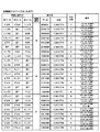
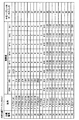
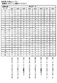
[図柄配置テーブル]
まず、図6を参照して、図柄配置テーブルについて説明する。図柄配置テーブルは、左リール3L、中リール3C及び右リール3Rのそれぞれの回転方向における各図柄の位置と、各位置に配された図柄の種類を特定するデータ(以下、図柄コード(図6中の図柄コード表を参照)という)との対応関係を規定する。
[Design arrangement table]
First, the symbol arrangement table will be described with reference to FIG. The symbol arrangement table is data (hereinafter referred to as symbol code (in FIG. 6) that specifies the position of each symbol in the rotation direction of each of the
図柄配置テーブルでは、リールインデックスが検出されたときに、表示窓4の枠内における各リールの中段領域に配置される図柄の位置を「0」と規定する。そして、各リールにおいて、図柄位置「0」を基準としてリールの回転方向(図6中の矢印A方向)に進む順に、図柄カウンタに対応する「0」〜「20」が、図柄位置として、各図柄に割り当てられる。
In the symbol arrangement table, the position of the symbol arranged in the middle area of each reel within the frame of the
すなわち、図柄カウンタの値(「0」〜「20」)と、図柄配置テーブルとを参照することにより、表示窓4の枠内における各リールの上段、中段及び下段の領域に表示されている図柄の種類を特定することができる。例えば、左リール3Lに対応する図柄カウンタの値が「7」であるとき、表示窓4の枠内における左リール3Lの上段、中段及び下段の領域には、それぞれ、図柄位置「8」の「リンゴ1」、図柄位置「7」の「ベル1」及び図柄位置「6」の「リプレイ2」に対応する図柄が表示されている。
That is, the symbols displayed in the upper, middle, and lower regions of each reel within the frame of the
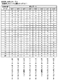
[図柄組合せテーブル]
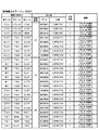
次に、図7〜図20を参照して、図柄組合せテーブルについて説明する。図柄組合せテーブルは、特典の種類に応じて予め定められた図柄の組合せと、表示役(格納領域)及び払出枚数との対応関係を規定する。
[Design combination table]
Next, the symbol combination table will be described with reference to FIGS. The symbol combination table defines a correspondence relationship between a symbol combination predetermined according to the type of privilege, a display combination (storage area), and a payout number.
本実施形態では、有効ライン(センターライン)に沿って、左リール3L、中リール3C及び右リール3Rにより表示される図柄の組合せが、図柄組合せテーブルに規定された図柄の組合せと一致する場合に入賞と判定される。そして、入賞と判定されると、メダルの払い出し、リプレイの作動といった特典が遊技者に与えられる。なお、有効ラインに沿って表示された図柄の組合せが、図柄組合せテーブルに規定されている図柄の組合せのいずれとも一致しない場合には、いわゆる「ハズレ」となる。すなわち、本実施形態では、「ハズレ」に対応する図柄の組合せを図柄組合せテーブルに規定しないことにより、「ハズレ」の図柄の組合せを規定する。なお、本発明はこれに限定されず、図柄組合せテーブルに、「ハズレ」の項目を設けて、直接「ハズレ」を規定してもよい。
In the present embodiment, when the symbol combination displayed by the
図柄組合せテーブル中の表示役欄に記載の各種データは、有効ラインに沿って表示された図柄の組合せを識別するためのデータである。この表示役欄の「データ」は、1バイトのデータで表され、該データ中の各ビットに対して固有の図柄の組合せ(表示役の内容)が割り当てられる。 Various data described in the display combination column in the symbol combination table is data for identifying a symbol combination displayed along the active line. “Data” in the display combination column is represented by 1-byte data, and a unique symbol combination (content of display combination) is assigned to each bit in the data.
また、表示役欄の「格納領域」のデータは、対応する表示役が格納される後述の表示役格納領域(後述の図60参照)を指定するためのデータである。なお、本実施形態では、42個の表示役格納領域を設ける。そして、本実施形態では、ビットパターン(1バイトのデータパターン)が同じであり、かつ、内容の異なる表示役は、「格納領域」の違いにより別の表示役として管理される。 The “storage area” data in the display combination column is data for designating a later-described display combination storage area (see FIG. 60 described later) in which the corresponding display combination is stored. In the present embodiment, 42 display combination storage areas are provided. In the present embodiment, display combinations having the same bit pattern (1-byte data pattern) and having different contents are managed as different display combinations depending on the “storage area”.
図柄組合せテーブル中の払出枚数欄に記載の数値は、遊技者に対して払い出すメダルの枚数を表す。「払出枚数」のデータとして1以上の数値が付与されている図柄の組合せでは、その数値と同じ枚数のメダルの払い出しが行われる。なお、本実施形態では、このようなメダルの払い出しが行われる表示役を「小役」と総称する。 The numerical value described in the payout number column in the symbol combination table represents the number of medals to be paid out to the player. In the combination of symbols to which a numerical value of 1 or more is given as the “paid-out number” data, the same number of medals are paid out. In the present embodiment, the display combination from which such medals are paid out is collectively referred to as “small combination”.
本実施形態では、例えば、表示役として「ベル」に係る表示役(図7〜図20の図柄組合せテーブルに示す「C_CLベル01」〜「C_XUベル12」のうちのいずれか)が決定されたときには、メダル3枚の投入枚数に対して、9枚のメダルの払い出しが行われる。また、例えば、表示役として「リンゴ」に係る表示役(図7〜図20の図柄組合せテーブルに示す「C_CLリンゴ01」〜「C_XUリンゴ08」のうちのいずれか)が決定された場合には、メダル3枚の投入枚数に対して、6枚のメダルの払い出しが行われる。
In this embodiment, for example, a display combination related to “Bell” (any one of “
また、本実施形態において、例えば、表示役としてリプレイに係る表示役(図7〜図20の図柄組合せテーブルに示す「C_RT1リプ01」〜「C_通常リプ24」に係る図柄の組合せのうちのいずれか)が決定されたときには、リプレイが作動する。
Further, in the present embodiment, for example, a display combination related to replay as a display combination (any of combinations of symbols related to “
なお、図7〜図20の図柄組合せテーブルに示す「R_RT1移行目1」〜「R_RT1移行目32」に係る表示役は、「特殊ベル」に係る図柄組合せを有効ライン上に停止表示できなかった(取りこぼした)際に表示される役であり、RT遊技状態が後述のRT1遊技状態(一般遊技状態)に移行する際の契機となる表示役である。それゆえ、有効ライン上に、「R_RT1移行目1」〜「R_RT1移行目32」のいずれかに対応する図柄組合せが停止表示された場合には、RT遊技状態が後述のRT1遊技状態に移行する。
In addition, the symbol combination related to “
[RT遷移テーブル]
次に、図21を参照して、RT遷移テーブルについて説明する。RT遷移テーブルは、RT遊技状態の移行条件と、移行元及び移行先のRT遊技状態との対応関係を規定する。
[RT transition table]
Next, the RT transition table will be described with reference to FIG. The RT transition table defines the correspondence relationship between the RT gaming state transition conditions and the transition source and destination RT gaming states.
本実施形態では、RT遊技状態として、リプレイの内部当籤役の種別及びその当籤確率が互いに異なる、RT0遊技状態〜RT7遊技状態の8種類の状態を設ける。そして、本実施形態では、図21に示すように、所定の役に係る図柄組合せが有効ライン上に停止表示されたことが、RT遊技状態間の移行契機となる。具体的には、「特殊ベルこぼし」に係る役の図柄組合せ、又は、各種リプレイ(「リプレイ1」〜「リプレイ6」、「リプレイ8」、「リプレイB」、「リプレイR」及び「リプレイP」)に係る役(以下、リプレイ役という)の図柄組合せが表示された場合に、RT遊技状態が移行する。
In the present embodiment, eight types of RT0 gaming states to RT7 gaming states are provided as RT gaming states, which are different in internal winning combination of replay and their winning probabilities. And in this embodiment, as shown in FIG. 21, it is a transition opportunity between RT gaming states that the symbol combination which concerns on a predetermined | prescribed role is stopped and displayed on the active line. Specifically, a combination of symbols related to “special bell spill” or various replays (“
RT遊技状態の移行契機となる「特殊ベルこぼし」に係る役の図柄組合せは、図7〜図20の図柄組合せテーブルで規定された「R_RT1移行目1」〜「R_RT1移行目32」のいずれかの図柄組合せである。また、RT遊技状態の移行契機となるリプレイ役の図柄組み合わせは、図7〜図20の図柄組合せテーブルで規定された「C_RT1リプ01」〜「C_RT7リプ12」のいずれかの図柄組合せである。
The combination of symbols related to the “special bell spill” that triggers the transition of the RT gaming state is any one of “
なお、本実施形態のパチスロ1では、主制御回路41(メインCPU51)は、RT遷移テーブルを参照して、RT遊技状態の遷移を制御するが、そのRT遊技状態の遷移フローの詳細については、後で図67を参照しながらより具体的に説明する。また、以下では、RT遊技状態を単に「RT状態」という。それゆえ、RT0遊技状態〜RT7遊技状態もまた、それぞれ「RT0状態」〜「RT7状態」という。
In the
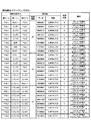
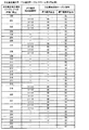
[内部抽籤テーブル]
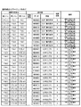
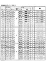
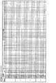
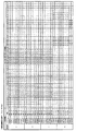
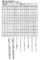
次に、図22〜図24を参照して、内部抽籤テーブルについて説明する。内部抽籤テーブルは、各RT状態における、当籤番号「0」〜「52」のそれぞれに対応付けられた小役・リプレイ用データポインタ「0」〜「52」と、該小役・リプレイ用データポインタが決定されるときの抽籤値との対応関係を規定する。
[Internal lottery table]
Next, an internal lottery table will be described with reference to FIGS. The internal lottery table includes the small role / replay data pointers “0” to “52” associated with the winning numbers “0” to “52” and the small role / replay data pointers in each RT state. The correspondence relationship with the lottery value when is determined.
小役・リプレイ用データポインタは、内部抽籤テーブルを参照して行う抽籤の結果として取得されるデータであり、後述の内部当籤役決定テーブル(図26〜図36参照)により規定される内部当籤役を指定するためのデータである。図22〜図24に示す内部抽籤テーブル中の、当籤番号(小役・リプレイ用データポインタ)「0」に対応して規定された抽籤値は、「ハズレ」に係る抽籤値である。また、当籤番号「1」〜「30」(略称「F_リプ0」〜「F_リプG9」)に対応して規定された抽籤値は、リプレイ役に係る抽籤値であり、当籤番号「31」〜「52」(略称「F_ベルALL」〜「F_リンゴ」)に対応して規定された抽籤値は、小役に係る抽籤値である。
The small combination / replay data pointer is data obtained as a result of lottery performed with reference to the internal lottery table, and is an internal symbol combination defined by an internal winning combination determination table (see FIGS. 26 to 36) described later. This is data for specifying. In the internal lottery tables shown in FIGS. 22 to 24, the lottery value defined corresponding to the winning number (small role / replay data pointer) “0” is the lottery value related to “losing”. Also, the lottery value defined corresponding to the winning numbers “1” to “30” (abbreviated names “
本実施形態では、図22〜図24中の各RT状態の欄に規定されている抽籤値を比較すると明らかなように、小役に係る抽籤値は、RT状態に関係なく同じである。しかしながら、リプレイ役に係る抽籤値の設定(当籤するリプレイ役の種別及びその抽籤値)はRT状態に応じて異なる。なお、各RT状態におけるリプレイ役に係る抽籤値の設定内容については、RT状態の遷移内容と合わせて、後で図67を参照しながらより具体的に説明する。 In the present embodiment, as is clear from comparison of lottery values defined in the respective RT state columns in FIGS. 22 to 24, the lottery value relating to the small role is the same regardless of the RT state. However, the setting of the lottery value related to the replay combination (the type of the replay combination to win and the lottery value thereof) varies depending on the RT state. Note that the setting contents of the lottery value relating to the replay combination in each RT state will be described more specifically with reference to FIG. 67 later together with the transition contents of the RT state.
本実施形態の内部抽籤処理では、まず、予め定められた数値の範囲(例えば、0〜65535)から抽出される乱数値を、各当籤番号に対応して規定された抽籤値で順次減算する。次いで、減算の結果が負になったか否か(いわゆる「桁かり」が生じたか否か)の判定(内部的な抽籤)を行う。そして、所定の当籤番号において減算の結果が負になった(「桁かり」が生じた)場合、その当籤番号に当籤したことになり、該当籤番号に割り当てられたデータポインタが取得される。 In the internal lottery processing of the present embodiment, first, random numbers extracted from a predetermined numerical range (for example, 0 to 65535) are sequentially subtracted by lottery values defined corresponding to each winning number. Next, it is determined (internal lottery) whether the result of the subtraction has become negative (whether a so-called “digit” has occurred). When the result of the subtraction becomes negative (a “digit” occurs) at a predetermined winning number, it means that the winning number is won, and the data pointer assigned to the corresponding winning number is acquired.
したがって、本実施形態の内部抽籤処理では、抽籤値として規定されている数値が大きい当籤番号ほど、割り当てられたデータ(データポインタ)が決定される確率が高い。なお、各当籤番号の当籤確率は、「各当籤番号に規定された抽籤値/抽出される可能性のある全ての乱数値の個数(乱数分母:65536)」によって表すことができる。 Therefore, in the internal lottery process of the present embodiment, the larger the number specified as the lottery value, the higher the probability that assigned data (data pointer) is determined. The winning probability of each winning number can be expressed by “the lottery value specified for each winning number / the number of all random numbers that may be extracted (random denominator: 65536)”.
具体的には、例えば、現在のRT状態がRT1状態である場合、当籤番号「0」(略称「ハズレ」)が当籤して小役・リプレイ用データポインタとして「0」が取得される確率(「ハズレ」に内部当籤する確率)は、「34256/65536」になる(図22参照)。また、例えば、現在のRT状態がRT1状態である場合、当籤番号「2」(略称「F_リプG1A」)が当籤して小役・リプレイ用データポインタとして「2」が取得される確率は、「5/65536」になる(図22参照)。さらに、例えば、現在のRT状態がRT1状態である場合、当籤番号「31」(略称「F_ベルALL」)が当籤して小役・リプレイ用データポインタとして「31」が取得される確率は、「819/65536」になる(図23参照)。 Specifically, for example, when the current RT state is the RT1 state, the winning number “0” (abbreviation “losing”) is won and the probability that “0” is acquired as the small role / replay data pointer ( The probability of internally winning “losing” is “34256/65536” (see FIG. 22). Further, for example, when the current RT state is the RT1 state, the probability that the winning number “2” (abbreviation “F_Lip G1A”) is won and “2” is acquired as the small role / replay data pointer is: “5/65536” (see FIG. 22). Further, for example, when the current RT state is the RT1 state, the probability that the winning number “31” (abbreviation “F_BELL ALL”) is won and “31” is acquired as the small role / replay data pointer is: It becomes “819/65536” (see FIG. 23).
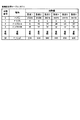
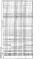
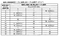
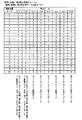
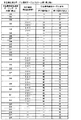
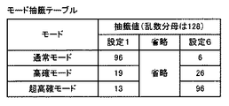
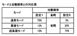
[抽籤値変更テーブル]
本実施形態では、RT1状態における小役・リプレイ用データポインタ「2」(当籤番号「2」)の当籤確率(期待値)の設定を予め変更することができる。図25は、RT1状態の抽籤値の設定を変更する際に用いる抽籤値変更テーブル(抽籤値設定変更手段)である。
[Lottery value change table]
In the present embodiment, the setting of the winning probability (expected value) of the small role / replay data pointer “2” (winning number “2”) in the RT1 state can be changed in advance. FIG. 25 is a lottery value change table (lottery value setting changing means) used when changing the setting of the lottery value in the RT1 state.
図25に示す例では、RT1状態の抽籤値を設定1〜設定6のいずれかに設定することができる。なお、図25中の設定1のRT1状態の抽籤値は、図22及び図23に示す内部抽籤テーブル中のRT1状態の欄に記載された抽籤値に対応する。 In the example shown in FIG. 25, the lottery value in the RT1 state can be set to any one of setting 1 to setting 6. Note that the lottery value in the RT1 state of setting 1 in FIG. 25 corresponds to the lottery value described in the RT1 state column in the internal lottery table shown in FIGS.
本実施形態では、小役・リプレイ用データポインタ「2」(当籤番号「2」)の抽籤値を、設定の数値(1〜6)の増加とともに、直線的に増加させる。具体的には、この例では、設定の数値が1増加すると、抽籤値が5増加するように抽籤値変更テーブルを設定する。 In the present embodiment, the lottery value of the small role / replay data pointer “2” (winning number “2”) is increased linearly as the set numerical value (1-6) increases. Specifically, in this example, the lottery value change table is set so that when the set numerical value increases by 1, the lottery value increases by 5.
本実施形態では、小役・リプレイ用データポインタ「2」(当籤番号「2」)の当籤確率の設定を予め変更することにより、遊技状態が後述の「通常遊技状態」(RT1又はRT7状態)から後述の「擬似ボーナス」(RT5状態:ART状態)に移行する際の契機となる表示役(本実施形態では、図25中の略称「F_リプG1A」に対応する役)を構成する左リール3Lの主な特定図柄(本実施形態では、図6中の図柄位置「5」の「リンゴ2」、図柄位置「4」の「赤7」及び図柄位置「3」の「リンゴ2」)が左リール3Lの中段領域に表示される確率を変更することができる。
In the present embodiment, by changing the winning probability setting of the small role / replay data pointer “2” (winning number “2”) in advance, the gaming state is a “normal gaming state” (RT1 or RT7 state) described later. The left reel constituting the display combination (in this embodiment, the combination corresponding to the abbreviation “F_Lip G1A” in FIG. 25) that triggers the transition from “Pseudo Bonus” (RT5 state: ART state) to be described later 3L main specific symbols (in this embodiment, “
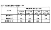
また、本実施形態では、後述の「擬似ボーナス」の遊技で参照するARTゲーム数の上乗せ抽籤テーブル(後述の図73参照)が、RT1状態の抽籤値変更テーブルの設定値に連動しており、設定の数値に応じて、上乗せ抽籤の当籤確率が変化する。具体的には、幸後述の上乗せ抽籤テーブルでは、設定の数値(1〜6)の増加とともに、「擬似ボーナス」の遊技における上乗せ抽籤の当籤確率(後述の「上乗せ演出」(リール演出)の発生頻度)が増加する。 In this embodiment, an additional lottery table (see FIG. 73 described later) for the number of ART games referred to in the “pseudo bonus” game described later is linked to the set value of the lottery value change table in the RT1 state. Depending on the set value, the winning probability of the extra lottery changes. Specifically, in the extra lottery table, which will be described later, as the set numerical value (1-6) increases, the winning probability of the extra lottery in the “pseudo bonus” game (the “extra effect” (reel effect) described later) occurs. Frequency).
それゆえ、本実施形態では、小役・リプレイ用データポインタ「2」(当籤番号「2」)の当籤確率の設定を予め変更することにより、後述の「擬似ボーナス」(ART状態)への移行契機となる表示役を構成する、左リール3Lの特定図柄が表示される確率を変更することができるとともに、後述の「擬似ボーナス」の遊技における上乗せ抽籤の当籤確率(後述の「上乗せ演出」(リール演出)の発生頻度)を変化させることができる。したがって、本実施形態では、後述の「擬似ボーナス」において、特定図柄が左リール3Lに停止表示される頻度を把握することにより、現在の設定の数値を予測することが可能になる。
Therefore, in the present embodiment, by changing the setting of the winning probability of the small role / replay data pointer “2” (winning number “2”) in advance, the transition to the “pseudo bonus” (ART state) described later is performed. It is possible to change the probability that a specific symbol of the
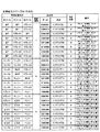
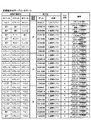
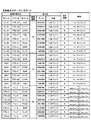
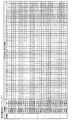
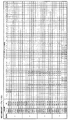
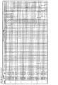
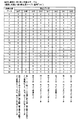
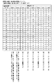
[内部当籤役決定テーブル]
次に、図26〜図36を参照して、内部当籤役決定テーブルについて説明する。内部当籤役決定テーブルは、小役・リプレイ用データポインタと、内部当籤役との対応関係を規定する。すなわち、小役・リプレイ用データポインタが決定されると、内部当籤役決定テーブルにより内部当籤役のデータが一義的に取得される。
[Internal winning combination determination table]
Next, an internal winning combination determination table will be described with reference to FIGS. The internal winning combination determination table defines the correspondence between the small winning combination / replay data pointer and the internal winning combination. That is, when the small combination / replay data pointer is determined, the internal winning combination data is uniquely acquired by the internal winning combination determination table.
内部当籤役決定テーブル中の「内部当籤役」は、有効ラインに沿って表示を許可する、左リール3L、中リール3C及び右リール3Rでの図柄の組合せを識別するためのデータである。「内部当籤役」は、図7〜図20に示した図柄組合せテーブル中の「表示役」と同様に、1バイトのデータで表され、該1バイトデータ中の各ビットに対して固有の図柄の組合せが割り当てられる。なお、小役・リプレイ用データポインタが「0」のとき、「内部当籤役」の内容は「ハズレ」となるが、これは、図7〜図20に示した図柄組合せテーブルにより規定されている全ての図柄の組合せの表示が許可されないことを示す。
The “internal winning combination” in the internal winning combination determination table is data for identifying a combination of symbols on the
図26〜図36は、本実施形態における小役・リプレイ用の内部当籤役決定テーブルの構成を示す図である。内部当籤役決定テーブルは、小役・リプレイ用データポインタの「1」〜「52」について、内部当籤する小役及びリプレイ役を規定する。すなわち、内部当籤役決定テーブルは、小役・リプレイ用データポインタと、メダルの払い出しに係る内部当籤役又はリプレイの作動に係る内部当籤役との対応関係を規定する。 FIG. 26 to FIG. 36 are diagrams showing the structure of the internal winning combination determination table for the small combination / replay in this embodiment. The internal winning combination determination table defines the internal winning combination and replay combination for “1” to “52” of the small combination / replay data pointer. In other words, the internal winning combination determination table defines a correspondence relationship between the small winning combination / replay data pointer and the internal winning combination relating to the payout of medals or the internal winning combination relating to the replay operation.
内部当籤役決定テーブル中の「○」印は、取得した小役・リプレイ用データポインタにおいて、当籤する内部当籤役を示す。例えば、小役・リプレイ用データポインタとして「2」が取得された場合には、内部当籤役として、「C_RT3リプ01」〜「C_RT3リプ46」、及び、「C_BBリプ01」〜「C_BBリプ13」が重複当籤する。また、例えば、小役・リプレイ用データポインタとして「31」が取得された場合には、内部当籤役として、「C_CLベル01」〜「C_CLベル08」、及び、「C_XUベル01」〜「C_XUベル12」が重複当籤する。
The “O” mark in the internal winning combination determination table indicates the internal winning combination to be won in the acquired small combination / replay data pointer. For example, when “2” is acquired as the small role / replay data pointer, “
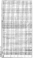
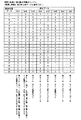
[回胴停止用番号選択テーブル]
次に、図37を参照して、回胴停止用番号選択テーブルについて説明する。回胴停止用番号選択テーブルは、小役・リプレイ用データポインタと、回胴停止用番号との対応関係を規定する。なお、回胴停止用番号は、後述のリール停止初期設定処理において必要とする各種データを取得するときに用いられるデータである。
[Cylinder stop number selection table]
Next, with reference to FIG. 37, the rotating cylinder stop number selection table will be described. The rotation stop number selection table defines the correspondence between the small role / replay data pointer and the rotation stop number. The rotation stop number is data used when acquiring various data required in the reel stop initial setting process described later.
本実施形態では、回胴停止用番号選択テーブルは、小役・リプレイ用データポインタ毎に異なる回胴停止用番号を規定する。例えば、小役・リプレイ用データポインタが「3」である場合には、回胴停止番号「3」が選択される。 In the present embodiment, the spinning cylinder stop number selection table defines different spinning cylinder stop numbers for each small role / replay data pointer. For example, when the data pointer for the small role / replay is “3”, the spinning stop number “3” is selected.
なお、本実施形態では、回胴停止用番号選択テーブルとしては、小役・リプレイ用データポインタ毎に異なる回胴停止番号を規定する例を示したが、本発明はこれに限定されない。異なる小役・リプレイ用データポインタに対して同一の回胴停止用番号を規定して、データの削減を図ってもよい。 In the present embodiment, the example of specifying the different rotation stop number for each small role / replay data pointer is shown as the rotation stop number selection table. However, the present invention is not limited to this. The same rotation stop number may be defined for different small role / replay data pointers to reduce data.
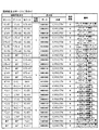
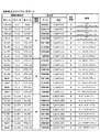
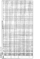
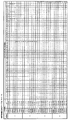
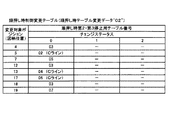
[リール停止初期設定テーブル]
次に、図38〜図40を参照して、リール停止初期設定テーブルについて説明する。リール停止初期設定テーブルは、回胴停止用番号と、後述の引込優先順位テーブル選択処理及び後述の各リールの滑り駒数の決定処理に用いられる各種データとの対応関係を規定する。具体的には、リール停止初期設定テーブルは、回胴停止用番号と、押下順序別判定データ(引込優先順位テーブル番号及び引込優先順位選択テーブル番号)、変則押し時テーブル番号選択値(変則押し時テーブル選択データ及び変更ステータス)、順押し時テーブル変更データ、順押し時テーブル選択データ、並びに、順押し時テーブル変更初期データ選択値(テーブル番号及び変更ステータス)との対応関係を規定する。
[Reel stop initial setting table]
Next, the reel stop initial setting table will be described with reference to FIGS. The reel stop initial setting table defines a correspondence relationship between the rotation stop number and various data used in a pull-in priority table selection process described later and a number of sliding pieces determination process of each reel described later. Specifically, the reel stop initial setting table includes the rotation stop number, determination data for each pressing order (retraction priority table number and retraction priority selection table number), irregular pressing table number selection value (alternating pressing) Table selection data and change status), forward push table change data, forward push table selection data, and forward push table change initial data selection values (table number and change status).
引込優先順位選択テーブル番号、及び、引込優先順位テーブル番号は、引込優先順位テーブル選択処理に用いられるデータである。例えば、リール停止初期設定テーブルにおいて、回胴停止用番号に対応する引込優先順位テーブル番号が規定されていれば、引込優先順位テーブル(後述の図57参照)に規定された引込優先順位テーブル番号に対応する表示役の優先順位に関するデータを取得することができる。また、リール停止初期設定テーブルにおいて、回胴停止用番号に対応する引込優先順位テーブル番号が規定されていなければ、引込優先順位テーブル選択テーブル(後述の図54〜図56参照)を参照し、引込優先順序選択テーブル番号に対応する引込優先順位選択テーブルデータに基づいて、引込優先順位テーブル番号が決定される。 The pull-in priority order selection table number and the pull-in priority order table number are data used for the pull-in priority order table selection process. For example, in the reel stop initial setting table, if a drawing priority table number corresponding to the number for turning stop is specified, the drawing priority table number specified in the drawing priority table (see FIG. 57 described later) is used. Data regarding the priority order of the corresponding display combination can be acquired. Further, in the reel stop initial setting table, if the drawing priority table number corresponding to the number for turning stop is not defined, the drawing priority table selection table (see FIGS. 54 to 56 described later) is referred to, and the drawing is performed. The drawing priority order table number is determined based on the drawing priority order selection table data corresponding to the priority order selection table number.
順押し時テーブル変更データ、順押し時テーブル選択データ、及び、順押し時テーブル変更初期データ選択値のテーブル番号は、順押しが行われた場合に参照する停止テーブル(後述の図41、図42及び図47〜図51参照)を指定するためのデータである。なお、本明細書でいう、「順押し」は、第1停止操作(1番目に行われる停止操作)が左リール3Lに対して行われた場合の停止操作であり、具体的には、「左中右」及び「左右中」の押し順で停止操作が行われた場合に対応する。
The table number of the table change data at the time of forward push, the table selection data at the time of push forward, and the initial data selection value at the time of table push change is a stop table to be referred to when forward push is performed (FIGS. And FIG. 47 to FIG. 51). In this specification, the “forward push” is a stop operation when the first stop operation (first stop operation) is performed on the
変則押し時テーブル選択データは、変則押しが行われた場合に参照するための停止テーブル(後述の図52及び図53参照)を指定するデータである。なお、本明細書でいう、「変則押し」は、第1停止操作が中リール3C又は右リール3Rに対して行われた場合の停止操作であり、「中左右」、「中右左」、「右中左」、及び、「右左中」の押し順で停止操作が行われた場合に対応する。
The irregular pressing table selection data is data for designating a stop table (see FIGS. 52 and 53 described later) to be referred to when irregular pressing is performed. In this specification, “anomalous push” is a stop operation when the first stop operation is performed on the
本実施形態では、基本的に、ストップスイッチ17Sにより停止操作が検出された後、該当するリールの回転が190msec以内に停止するように制御される。具体的には、停止操作が検出されたときの該当リールに応じた図柄カウンタの値に、滑り駒数「0」〜「4」のうちの何れかを加算し、得られた値に対応する図柄位置を、リールの回転が停止する図柄位置(これを「停止予定位置」という)として決定する。なお、停止操作が検出されたときの該当リールに応じた図柄カウンタの値に対応する図柄位置は、リールの回転の停止が開始される図柄位置であり、これを「停止開始位置」という。
In the present embodiment, basically, after the stop operation is detected by the
つまり、滑り駒数は、ストップスイッチ17Sにより停止操作が検出されてから該当するリールの回転が停止するまでのリールの回転量である。言い換えれば、ストップスイッチ17Sにより停止操作が検出されてから該当するリールの回転が停止するまでの期間において、表示窓4の該当するリールの中段領域を通過する図柄の数である。これは、ストップスイッチ17Sにより停止操作が検出されてから更新された図柄カウンタの値により把握される。
In other words, the number of sliding pieces is the amount of rotation of the reel from when the stop operation is detected by the
停止テーブルを参照すると、各リールの停止開始位置に応じて滑り駒数が取得される。なお、本実施形態では、停止テーブルに基づいて滑り駒数が取得されるが、これは仮のものであり、取得した滑り駒数が直ちにリールの停止予定位置が決定されるものではない。 Referring to the stop table, the number of sliding pieces is acquired according to the stop start position of each reel. In the present embodiment, the number of sliding pieces is acquired based on the stop table, but this is a tentative one, and the acquired number of sliding pieces does not immediately determine the planned stop position of the reel.
また、本実施形態では、後述の停止テーブルに基づいて取得された滑り駒数(以下、「滑り駒数決定データ」という)より適切な滑り駒数が存在する場合は、後述する引込優先順位テーブル(後述の図57参照)を参照して滑り駒数を変更する。そして、滑り駒数決定データは、停止開始位置から最大滑り駒数である4個先の図柄位置までの各図柄について、優先順位の比較を行う際の検索順序を決定するめに参照される。 In the present embodiment, when there is an appropriate number of sliding pieces than the number of sliding pieces acquired based on a stop table described later (hereinafter referred to as “sliding piece number determination data”), a pull-in priority table described later The number of sliding pieces is changed with reference to (see FIG. 57 described later). Then, the sliding piece number determination data is referred to in order to determine the search order when the priority order is compared for each of the symbols from the stop start position to the 4th symbol position that is the maximum number of sliding symbols.
本実施形態では、順押し及び変則押しに応じて、参照する停止テーブルを使い分ける。順押しであれば、順押し時第1停止用停止テーブル(後述の図41及び図42参照)と、順押し時第2・第3停止用停止テーブル(後述の図47〜図51参照)とを参照する。一方、変則押しであれば、変則押し時停止テーブル(後述の図52及び図53参照)を参照する。 In the present embodiment, the stop table to be referenced is properly used according to the forward push and the irregular push. If it is a forward press, the first stop table for forward pressing (see FIGS. 41 and 42 described later), the second and third stop tables for forward pressing (see FIGS. 47 to 51 described later), and Refer to On the other hand, if it is an irregular push, refer to the irregular push stop table (see FIGS. 52 and 53 described later).
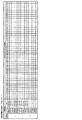
[順押し時第1停止用停止テーブル]
次に、図41及び図42を参照して、順押し時第1停止用停止テーブルについて説明する。順押し時第1停止用停止テーブルは、順押し時テーブル選択データ「00」〜「07」のそれぞれにおいて、左リール3Lの停止開始位置「0」〜「20」と、滑り駒数決定データ及びチェンジステータスとの対応関係を規定する。なお、チェンジステータスは、後述する順押し時制御変更テーブル(後述の図43〜図46参照)を参照するときに用いられる。
[Stop table for first stop when pushing forward]
Next, with reference to FIG. 41 and FIG. 42, the stop table for the first stop at the time of forward pressing will be described. The stop table for the first stop at the time of the forward press is the stop start position “0” to “20” of the
ここで、一例として、小役・リプレイ用データポインタ「2」(当籤番号「2」)に当籤した場合における、左リール3Lの上述した特定図柄(図6中の図柄位置「5」の「リンゴ2」、図柄位置「4」の「赤7」及び図柄位置「3」の「リンゴ2」)の停止動作について説明する。
Here, as an example, when the small pointer / replay data pointer “2” (winning number “2”) is won, the above-mentioned specific symbol of the
小役・リプレイ用データポインタ「2」(当籤番号「2」)が取得された場合、図37に示す回胴停止用番号選択テーブルから、回胴停止番号「2」が取得される。この場合、図38のリール停止初期設定テーブルに示すように、順押し時テーブル選択データ「02」が取得される。すなわち、小役・リプレイ用データポインタ「2」(当籤番号「2」)が取得され(略称「F_リプG1A」に対応する当籤役が当籤し)、左リール3Lに対して第1停止操作が行われた場合には、図41の順押し時第1停止用停止テーブル中の順押し時テーブル選択データ「02」の欄に記載の滑り駒数決定データが参照される。
When the small role / replay data pointer “2” (winning number “2”) is acquired, the rotation stop number “2” is acquired from the rotation stop number selection table shown in FIG. In this case, as shown in the reel stop initial setting table of FIG. 38, the forward selection table selection data “02” is acquired. In other words, the small role / replay data pointer “2” (winning number “2”) is acquired (the winning combination corresponding to the abbreviation “F_Lip G1A” is won), and the first stop operation is performed on the
この場合、例えば、左リール3Lに対して図柄位置「4」のタイミングで停止操作が行われると(ストップボタンが押下されると)、滑り駒数決定データは「0」(滑り駒数は「0」)となり、停止操作が行われた際に判定ライン上に位置する図柄(「赤7」)が停止表示される。また、例えば、左リール3Lに対して図柄位置「5」のタイミングで停止操作が行われると、滑り駒数決定データは「0」(滑り駒数は「0」)となり、停止操作が行われた際に判定ライン上に位置する図柄(「リンゴ2」)が停止表示される。さらに、例えば、左リール3Lに対して図柄位置「3」のタイミングで停止操作が行われると、滑り駒数決定データは「2」(滑り駒数は「2」)となり、停止操作が行われた際に判定ライン上に位置する図柄(「リンゴ2」)の2個先の図柄(「リンゴ2」)が停止表示される。
In this case, for example, when a stop operation is performed on the
すなわち、小役・リプレイ用データポインタ「2」(当籤番号「2」)が取得され、左リール3Lに対して第1停止操作が行われた場合において、上述した特定図柄が判定ライン上に位置するタイミングで停止操作を行うと、必ず、対応する特定図柄が停止表示される。
That is, when the small role / replay data pointer “2” (winning number “2”) is acquired and the first stop operation is performed on the
[順押し時制御変更テーブル]
次に、図43〜図46を参照して、順押し時制御変更テーブルについて説明する。なお、図43は、順押し時テーブル変更データが「00」である場合の順押し時制御変更テーブルであり、図44は、順押し時テーブル変更データが「01」である場合の順押し時制御変更テーブルである。また、図45は、順押し時テーブル変更データが「02」である場合の順押し時制御変更テーブルであり、図46は、順押し時テーブル変更データが「03」である場合の順押し時制御変更テーブルである。
[Control change table when pressing forward]
Next, with reference to FIGS. 43 to 46, the forward-pressing control change table will be described. 43 is a control change table at the time of forward pressing when the table change data at the time of forward pressing is “00”, and FIG. 44 is at the time of forward pressing when the table change data at the time of forward pressing is “01”. It is a control change table. 45 is a control change table at the time of forward push when the table change data at the time of forward push is “02”, and FIG. 46 is at the time of forward push when the table change data at the time of forward push is “03”. It is a control change table.
順押し時制御変更テーブルは、変更対象ポジション(左リール3Lの停止予定位置)と、チェンジステータスと、順押し時第2・第3停止用停止テーブル番号との対応関係を規定する。例えば、リール停止初期設定テーブル(図38〜図40参照)に基づいて取得された順押し時テーブル変更データが「00」であり、順押し時第1停止用停止テーブル(図41及び図42参照)に基づいて取得されたチェンジステータスが「0」であり、かつ、左リール3Lの停止予定位置が「18」であれる場合には、図43に示す順押し時制御変更テーブルが参照され、順押し時第2・第3停止用停止テーブル番号は「11(Bライン)」になる。なお、順押し時制御変更テーブルにおいて、対象位置に変更テーブルデータが登録されていない場合には、停止テーブル番号は変更しない。
The forward pressing control change table defines the correspondence between the change target position (scheduled stop position of the
[順押し時第2・第3停止用停止テーブル及び変則押し時停止テーブル]
次に、図47〜図53を参照して、順押し時第2・第3停止用停止テーブル及び変則押し時停止テーブルについて説明する。順押し時第2・第3停止用停止テーブル及び変則時停止テーブルは、図柄位置「0」〜「20」のそれぞれに応じて1バイトの停止データを規定する。
[Stop table for 2nd and 3rd stop when pushing forward and stop table when pushing irregularly]
Next, with reference to FIGS. 47 to 53, the second and third stop tables for forward pressing and the stop table for irregular pressing will be described. The stop table for the second and third stops and the stop table for irregularity when pushing forward define 1-byte stop data according to each of the symbol positions “0” to “20”.
なお、図47に示す順押し時第2・第3停止用停止テーブルは、順押し時第2・第3停止用停止テーブル番号が「00」である場合に参照される。図48に示す順押し時第2・第3停止用停止テーブルは、順押し時第2・第3停止用停止テーブル番号が「15」である場合に参照される。図49に示す順押し時第2・第3停止用停止テーブルは、順押し時第2・第3停止用停止テーブル番号が「12」である場合に参照される。図50に示す順押し時第2・第3停止用停止テーブルは、順押し時第2・第3停止用停止テーブル番号が「19」である場合に参照される。また、図51に示す順押し時第2・第3停止用停止テーブルは、順押し時第2・第3停止用停止テーブル番号が「20」である場合に参照される。 47 is referred to when the second / third stop table for stop is “00”. 48 is referred to when the stop table number for the second and third stops at the time of forward pressing is “15”. 49 is referred to when the stop table number for the second and third stops at the time of forward pressing is “12”. 50 is referred to when the stop table number for the second and third stops at the time of forward pressing is “19”. Further, the second- and third-stop stop tables for forward pressing shown in FIG. 51 are referred to when the second- and third-stop stop table numbers for forward pressing are “20”.
図52に示す変則押し時停止テーブルは、変則押し時テーブル選択データが「00」のときに参照される。また、図53に示す変則押し時停止テーブルは、変則押し時テーブル選択データが「01」のときに参照される。 The irregular pressing stop table shown in FIG. 52 is referred to when the irregular pressing table selection data is “00”. The irregular pressing stop table shown in FIG. 53 is referred to when the irregular pressing table selection data is “01”.
順押し時第2・第3停止用停止テーブル及び変則押し時停止テーブルの各停止テーブルで規定される停止データは、それ自身が対応付けられている図柄位置がリールの回転を停止する位置として適切か否かの情報を有する。そして、この停止データは、対応する図柄位置がリールの回転を停止する位置として適切か否かの情報を、各停止テーブル中の「Aライン」の列に対応するビット及び「Bライン」の列に対応するビットに割り当てる。また、停止データは、これら2種類の情報のうち何れを採用すべきかの情報を、各停止テーブル中の「ライン変更」の列に対応するビットに割り当てて規定される。 The stop data specified by the stop tables for the second and third stoppages at the time of forward pressing and the stop table at the time of irregular pressing is appropriate as the position at which the symbol position associated with the stop data stops the rotation of the reel. Whether or not. The stop data includes information indicating whether or not the corresponding symbol position is appropriate as a position to stop the rotation of the reel, the bit corresponding to the “A line” column and the “B line” column in each stop table. Assign to the bit corresponding to. The stop data is defined by assigning information about which of these two types of information should be adopted to the bit corresponding to the “line change” column in each stop table.
すなわち、順押し時第2・第3停止用停止テーブル及び変則押し時停止テーブルは、リールの回転を停止する位置の決め方を複数通り規定している。したがって、停止開始位置が同じ図柄位置であっても、第1停止時の停止位置などに基づいてリールの回転を停止する位置を異ならせることが可能となる。このような構成を採用することにより、情報の圧縮化を図ることができる。 That is, the second and third stop tables for forward pressing and the stop table for irregular pressing define a plurality of methods for determining the position at which the rotation of the reel is stopped. Therefore, even if the stop start position is the same symbol position, the position where the reel rotation is stopped can be varied based on the stop position at the time of the first stop. By adopting such a configuration, it is possible to compress information.
なお、滑り駒数決定データの決定は、次のようにして行われる。まず、停止操作が検出されたストップボタンの種別に応じて停止データを構成する8つのビット列(図中の左端の列のデータがビット1に対応)の何れを参照するかを指定する。例えば、中ストップボタン17Cが押されたとき、ビット4の「中リールAラインデータ」の列が指定される。
The determination of the number of sliding piece determination data is performed as follows. First, it is specified which of the eight bit strings (the data in the leftmost column in the figure corresponds to bit 1) constituting the stop data is referred to according to the type of the stop button in which the stop operation is detected. For example, when the
そして、指定されたビット列を参照し、停止開始位置から最大の滑り駒数の範囲までの各図柄位置について、対応するデータとして「1」が規定されているか否かの検索を順次行う。この検索の結果、停止開始位置から、対応するデータとして「1」が規定されている図柄位置までの差分を算出し、該差分を滑り駒数決定データとする。 Then, referring to the designated bit string, a search is sequentially performed as to whether or not “1” is defined as the corresponding data for each symbol position from the stop start position to the range of the maximum number of sliding symbols. As a result of this search, the difference from the stop start position to the symbol position where “1” is defined as the corresponding data is calculated, and this difference is used as the number of sliding piece determination data.
なお、参照するビット列を「Aライン」の列から「Bライン」の列へ変更するか否かは、「ライン変更」の列を参照し、停止開始位置に対応するデータに「1」が規定されているか否かによって決定される。次いで、ライン変更を行うと決定されたときには、それ以降、「Bライン」の列が指定され、上記検索が行われる。そして、検索結果に基づいて滑り駒数決定データを取得する。 Whether or not the bit string to be referred to is changed from the “A line” column to the “B line” column refers to the “line change” column and “1” is defined in the data corresponding to the stop start position. It is determined by whether or not. Next, when it is decided to change the line, the column “B line” is designated thereafter, and the above search is performed. Then, the number of sliding piece determination data is acquired based on the search result.
[引込優先順位テーブル選択テーブル]
次に、図54〜図56を参照して、引込優先順位テーブル選択テーブルについて説明する。なお、図54に示す引込優先順位テーブル選択テーブルは、左リール3Lが第1停止された際に参照されるテーブルであり、図55に示す引込優先順位テーブル選択テーブルは、中リール3Cが第1停止された際に参照されるテーブルであり、図56に示す引込優先順位テーブル選択テーブルは、右リール3Rが第1停止された際に参照されるテーブルである。
[Pull-in priority table selection table]
Next, the pull-in priority table selection table will be described with reference to FIGS. The pull-in priority table selection table shown in FIG. 54 is a table that is referred to when the
各引込優先順位テーブル選択テーブルは、引込優先順位選択テーブルデータとストップボタンの押下順との組合せと、各組合せにおける引込優先順位テーブル番号との対応関係を規定する。なお、各引込優先順位テーブル選択テーブルに規定されている引込優先順位テーブル番号は、引込優先順位テーブル(後述の図57参照)に規定された表示役の優先順位に関する情報を取得するためのデータである。 Each pull-in priority table selection table defines the correspondence between the pull-in priority selection table data and the stop button pressing order, and the pull-in priority table number in each combination. The pull-in priority table number defined in each pull-in priority table selection table is data for acquiring information related to the priority of the display combination defined in the pull-in priority table (see FIG. 57 described later). is there.
また、各引込優先順位テーブル選択テーブルに規定されている引込優先順位選択テーブルデータは、図38〜図40のリール停止初期設定テーブルを参照して取得された引込優先順位選択テーブル番号に基づいて決定される。具体的には、3桁からなる引込優先順位選択テーブルデータのうち、下2桁の数値は引込優先順位選択テーブル番号に対応する。そして、引込優先順位選択テーブルデータの上1桁の数値が、第1停止されたリールの種別に対応する。 The pull-in priority selection table data defined in each pull-in priority table selection table is determined based on the pull-in priority selection table number acquired with reference to the reel stop initial setting tables in FIGS. Is done. Specifically, in the drawing priority order selection table data consisting of three digits, the numerical value of the last two digits corresponds to the drawing priority order selection table number. The first digit value of the pull-in priority selection table data corresponds to the type of the first stopped reel.
本実施形態では、左リール3Lが第1停止された場合には引込優先順位選択テーブルデータの上1桁の数値を「1」とし、中リール3Cが第1停止された場合には引込優先順位選択テーブルデータの上1桁の数値を「2」とし、右リール3Rが第1停止された場合には引込優先順位選択テーブルデータの上1桁の数値を「3」とする。それゆえ、例えば、左リール3Lが第1停止され、リール停止初期設定テーブルを参照して取得された引込優先順位選択テーブル番号が「11」である場合には、引込優先順位選択テーブルデータは「111」となり、右リール3Rが第1停止され、リール停止初期設定テーブルを参照して取得された引込優先順位選択テーブル番号が「11」である場合には、引込優先順位選択テーブルデータは「311」となる。
In this embodiment, when the
ここで、引込優先順位テーブル選択テーブルの参照手順(引込優先順位テーブル番号の決定手順)の一例を説明する。なお、引込優先順位テーブル選択テーブルは、リールの停止操作毎に実行される。例えば、左リール3Lが第1停止され、リール停止初期設定テーブルを参照して取得された引込優先順位選択テーブル番号が「11」である場合、図54に示す引込優先順位テーブル選択テーブル中の引込優先順位選択テーブルデータ「111」の欄に記載の情報を参照する。
Here, an example of a reference procedure for the pull-in priority table selection table (a procedure for determining the pull-in priority table number) will be described. The pull-in priority table selection table is executed for each reel stop operation. For example, when the
次いで、第2停止操作されたリールの種別を判別し、引込優先順位選択テーブルデータの押下順序「1−X−2」の欄の情報を参照する。なお、押下順序「1−X−2」は、左リール3L及び右リール3Rがこの順で停止操作されたことを示す。この際、第2停止操作が右リール3Rに対して行われた場合には、押下順序「1−X−2」に該当する(押し順正解)ので、引込優先順位テーブル番号「01」が取得される。一方、第2停止操作が中リール3Cに対して行われた場合には、押下順序「1−X−2」に該当しない(押し順不正解)ので、引込優先順位テーブル番号「02」が取得される。
Next, the type of the reel that has been subjected to the second stop operation is determined, and the information in the column “1-X-2” of the pull-in priority selection table data is referred to. The pressing order “1-X-2” indicates that the
その後、第3停止操作された場合、その際のリールの種別を判別し、引込優先順位選択テーブルデータの押下順序「1−3−2」の欄の情報が参照される。なお、押下順序「1−3−2」は、左リール3L、右リール3R及び中リール3Cがこの順で停止操作されたことを示す。この際、第3停止操作が右リール3Rに対して行われた場合には、押下順序「1−3−2」に該当しない(押し順不正解)ので、引込優先順位テーブル番号「02」が取得される(第2停止操作時に取得した引込優先順位テーブル番号が維持される)。一方、第3停止操作が中リール3Cに対して行われた場合には、押下順序「1−3−2」に該当(押し順正解)するので、引込優先順位テーブル番号「01」が取得される(第2停止操作時に取得した引込優先順位テーブル番号が維持される)。
Thereafter, when the third stop operation is performed, the type of the reel at that time is determined, and the information in the column “1-3-2” of the pull-down order selection table data is referred to. The pressing order “1-3-2” indicates that the
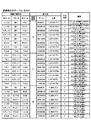
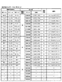
[引込優先順位テーブル]
次に、図57を参照して、引込優先順位テーブルについて説明する。引込優先順位テーブルは、引込優先順位テーブル番号「00」〜「02」のそれぞれにおける、格納領域種別毎の引込データと、予め定められたその優先順位との対応関係を規定する。
[Pull-in priority table]
Next, the drawing priority table will be described with reference to FIG. The pull-in priority table defines the correspondence between the pull-in data for each storage area type and the predetermined priority in each of the pull-in priority table numbers “00” to “02”.
引込優先順位テーブルは、停止テーブルに基づいて得られた滑り駒数の他に、より適切な滑り駒数が存在するか否かを検索するために使用される。優先順位は、入賞に係る図柄の組合せの種別間で優先的に停止表示される(引き込まれる)順位を規定するデータである。また、各引込データは、図26〜図36に示した内部当籤役決定テーブル中の「内部当籤役」や図7〜図20に示した図柄組合せテーブル中の「表示役」と同様に、1バイトのデータで表され、該1バイトデータ中の各ビットに対して固有の図柄の組合せが割り当てられる。 The pull-in priority order table is used for searching whether there is a more appropriate number of sliding pieces in addition to the number of sliding pieces obtained based on the stop table. The priority order is data that defines the order of priority stop display (drawn) between the types of symbol combinations related to winning. Each pull-in data is similar to “internal winning combination” in the internal winning combination determination table shown in FIGS. 26 to 36 and “display combination” in the symbol combination table shown in FIGS. It is represented by byte data, and a unique symbol combination is assigned to each bit in the one-byte data.
本実施形態では、まず、上述の順押し時第1停止用停止テーブル(図41〜図42参照)に基づいて滑り駒数が取得される。しかしながら、この滑り駒数の他に、より適切な滑り駒数が存在する場合には、その適切な滑り駒数に変更する。すなわち、本実施形態では、停止テーブルにより取得された滑り駒数に関係なく、内部当籤役によって停止表示を許可する図柄の組合せの優先順位に基づいて、より適切な滑り駒数を決定する。 In the present embodiment, first, the number of sliding pieces is acquired based on the above-described first stop stop table (see FIGS. 41 to 42) at the time of forward pressing. However, when there is a more appropriate number of sliding pieces in addition to the number of sliding pieces, the number is changed to the appropriate number of sliding pieces. In other words, in the present embodiment, a more appropriate number of sliding symbols is determined based on the priority of the combination of symbols that allow the stop display by the internal winning combination regardless of the number of sliding symbols acquired from the stop table.
本実施形態では、図57に示すように、引込優先順位テーブル番号に応じて内部当籤役の優先順位が異なるだけでなく、優先順位の区分数も異なる。具体的には、引込優先順位テーブル番号が「00」である場合には、優先順位の区分数を1とし、引込優先順位テーブル番号が「01」である場合には、優先順位の区分数を2とし、そして、引込優先順位テーブル番号が「02」である場合には、優先順位の区分数を3とする。なお、ここでは、説明を簡略化するため、引込優先順位テーブル番号が「01」である場合の優先順位について説明し、それ以外の引込優先順位テーブル番号における優先順位の説明は省略する。 In the present embodiment, as shown in FIG. 57, not only does the priority of the internal winning combination differ according to the pull-in priority table number, but the number of priority divisions also differs. Specifically, when the pull-in priority table number is “00”, the number of priority sections is set to 1. When the pull-in priority table number is “01”, the number of priority sections is set. 2 and when the pull-in priority table number is “02”, the priority division number is set to 3. Here, in order to simplify the description, the priority when the pull-in priority table number is “01” will be described, and the description of the priorities in other pull-in priority table numbers will be omitted.
引込優先順位テーブル番号が「01」である場合、優先順位「1」には、「C_RT1リプ01」〜「C_RT1リプ08」、「C_RT3リプ01」〜「C_RT3リプ46」、「C_RT4リプ01」〜「C_RT4リプ42」、「C_PBリプ01」〜「C_PBリプ09」、「C_RT7リプ01」〜「C_RT7リプ12」、及び、「C_XDベル01」〜「C_XDベル12」に対応する引込データが規定される。優先順位「2」には、「R_RT1移行目1」〜「R_RT1移行目32」、「C_RT5リプ01」〜「C_RT5リプ18」、「C_通常リプ01」〜「C_通常リプ24」、及び、「C_CLベル01」〜「C_CLベル08」に対応する引込データが規定される。
When the pull-in priority table number is “01”, the priority “1” includes “
そして、引込優先順位テーブル番号が「01」である場合には、優先順位「1」に規定された内部当籤役に対応する図柄組合せの停止表示(引き込み)が、その他の図柄組合せの停止表示よりも優先的に行われる。 If the drawing priority table number is “01”, the symbol combination stop display (withdrawal) corresponding to the internal winning combination defined in the priority “1” is displayed from other symbol combination stop displays. Is also given priority.
[検索順序テーブル]
次に、図58を参照して、検索順序テーブルについて説明する。検索順序テーブルは、滑り駒数として予め定められた数値の範囲(最大滑り駒数が4コマの場合は「0」〜「4」)の中から優先的に適用する順序(以下、「検索順序」という)を規定する。
[Search order table]
Next, the search order table will be described with reference to FIG. The search order table preferentially applies from the range of numerical values predetermined as the number of sliding frames (“0” to “4” when the maximum number of sliding frames is 4) (hereinafter referred to as “search order”). ").
検索順序テーブルは、上述した停止テーブルに基づいて得られた滑り駒数決定データと、その検索順序とを規定する。すなわち、本実施形態では、滑り駒数決定データに基づいて、優先的に適用する数値の順序が決定される。また、検索順序テーブルは、優先順位が等しい滑り駒数が複数存在する場合を想定して設けられたものであり、検索順序がより上位であるものを適用する構成になっている。 The search order table defines the sliding piece number determination data obtained based on the stop table and the search order. That is, in this embodiment, the order of numerical values to be preferentially applied is determined based on the sliding piece number determination data. In addition, the search order table is provided assuming that there are a plurality of sliding frames having the same priority, and the search order table is applied in a higher order.
なお、本実施形態では、後述の図104の優先引込制御処理で説明するように、検索順序テーブルの下位の検索順序「5」から順次、各数値の検索を行い、検索順序「1」に対応する数値から優先的に滑り駒数として適用されるようにする。 In the present embodiment, as described in the priority attraction-in control process in FIG. 104 described later, each numerical value is searched sequentially from the lower search order “5” of the search order table, and the search order “1” is supported. The number of sliding frames is preferentially applied from the numerical value to be used.
[図柄対応入賞作動フラグデータテーブル]
次に、図59を参照して、図柄対応入賞作動フラグデータテーブルについて説明する。図柄対応入賞作動フラグデータテーブルは、リール種別と、入賞判定ラインに表示された各リールの図柄に応じて表示可能な内部当籤役のデータとの対応関係を規定する。すなわち、図柄対応入賞作動フラグデータテーブルを参照することにより、そのときに表示可能な内部当籤役を判別することができる。なお、図柄対応入賞作動フラグデータテーブルは、図柄組合せテーブル(図7〜図20参照)に対応して設けられる。
[Pattern winning action flag data table]
Next, the symbol corresponding winning action flag data table will be described with reference to FIG. The symbol corresponding winning action flag data table defines the correspondence between the reel type and the internal winning combination data that can be displayed according to the symbol of each reel displayed on the winning determination line. That is, by referring to the symbol corresponding winning action flag data table, the internal winning combination that can be displayed at that time can be determined. The symbol corresponding winning action flag data table is provided corresponding to the symbol combination table (see FIGS. 7 to 20).
例えば、左リール3Lの入賞判定ライン上に図柄「赤7」が停止表示された場合には、リール種別「左」における図柄コード「00000001」(赤7)に対応する格納領域1〜42において、表示可能な内部当籤役に対応するビットに「1」が格納される。この図柄対応入賞作動フラグデータテーブルで規定されるデータは、後述の図柄コード格納領域(後述の図64参照)に格納されるデータに論理積して格納される。
For example, when the symbol “red 7” is stopped and displayed on the winning determination line of the
<メインRAMに設けられている格納領域の構成>
次に、図60〜図66を参照して、メインRAM53に設けられている各種格納領域の構成について説明する。なお、ここでは、説明を省略するが(図示しないが)、後述の各種リール演出やランダム加速処理などで用いる演出用乱数値、各種制御データ、各種フラグ、各種カウンタ等の格納領域もメインRAM53に設けられる。
<Configuration of storage area provided in main RAM>
Next, the configuration of various storage areas provided in the
[表示役格納領域]
まず、図60を参照して、表示役格納領域の構成について説明する。本実施形態では、表示役格納領域は、それぞれ1バイトのデータにより表される表示役格納領域1〜42で構成される。
[Display combination storage area]
First, the configuration of the display combination storage area will be described with reference to FIG. In the present embodiment, the display combination storage area includes display
表示役格納領域1〜42のそれぞれにおいて、所定のビットに「1」が立っているとき(格納されているとき)、その所定のビットに対応する図柄の組合せが有効ライン上に表示されたことを示す。一方、全ビットが「0」であるとき、入賞に係る図柄の組合せが有効ライン上に表示されなかったことを示す。
In each of the display
また、メインRAM53には、内部当籤役格納領域(不図示)が設けられる。内部当籤役格納領域は、図60に示す表示役格納領域と同様に構成される。内部当籤役格納領域1〜42において、複数のビットに「1」が立っているときは、各ビットにそれぞれ対応する図柄の組合せの表示が許可される。また、全ビットが「0」であるとき、内部当籤役の内容は「ハズレ」となる。
The
[遊技状態フラグ格納領域]
次に、図61を参照して、遊技状態フラグ格納領域の構成について説明する。遊技状態フラグ格納領域は、1バイトからなる遊技状態フラグを格納する。本実施形態では、遊技状態フラグにおいて、各ビットに、RT状態の種別が割り当てられる。
[Game state flag storage area]
Next, the configuration of the game state flag storage area will be described with reference to FIG. The gaming state flag storage area stores a gaming state flag consisting of 1 byte. In the present embodiment, the RT state type is assigned to each bit in the gaming state flag.
遊技状態フラグ格納領域において、所定のビットに「1」が格納されている(立っている)とき、その所定のビットに該当するRTの作動が行われていることを示す。例えば、遊技状態フラグ格納領域のビット0に「1」が格納されているときは、現在のRT状態がRT7状態であることを示す。
When “1” is stored (standing) in a predetermined bit in the gaming state flag storage area, it indicates that the RT corresponding to the predetermined bit is being operated. For example, when “1” is stored in
[作動ストップボタン格納領域]
次に、図62を参照して、作動ストップボタン格納領域の構成について説明する。作動ストップボタン格納領域は、1バイトからなる作動ストップボタンフラグを格納する。作動ストップボタンフラグにおいて、各ビットには、ストップボタンの操作状態が割り当てられる。
[Operation stop button storage area]
Next, the configuration of the operation stop button storage area will be described with reference to FIG. The operation stop button storage area stores an operation stop button flag consisting of 1 byte. In the operation stop button flag, the operation state of the stop button is assigned to each bit.
例えば、左ストップボタン17Lが今回押されたストップボタン、つまり、作動ストップボタンである場合には、作動ストップボタン格納領域のビット0に「1」が格納される。また、例えば、左ストップボタン17Lが未だに押されていないストップボタン、つまり、有効ストップボタンである場合には、ビット4に「1」が格納される。メインCPU51は、作動ストップボタン格納領域に格納されているデータに基づいて、今回押されたストップボタンと未だに押されていないストップボタンとを識別する。
For example, if the
[押下順序格納領域]
次に、図63を参照して、押下順序格納領域の構成について説明する。押下順序格納領域は、1バイトからなる押下順序フラグを格納する。押下順序フラグにおいて、各ビットには、ストップボタンの押下順序の種別が割り当てられる。例えば、ストップボタンの押下順序が「左中右」である場合には、押下順序格納領域のビット0に「1」が格納される。
[Push order storage area]
Next, the configuration of the pressing order storage area will be described with reference to FIG. The pressing order storage area stores a pressing order flag consisting of 1 byte. In the pressing order flag, the type of stop button pressing order is assigned to each bit. For example, when the pressing order of the stop button is “left middle right”, “1” is stored in
[図柄コード格納領域]
次に、図64を参照して、図柄コード格納領域の構成について説明する。図柄コード格納領域には、有効ライン毎に、直近に停止操作されたリールの図柄の図柄コード(図柄コード格納領域1)と、表示可能な役(図柄コード格納領域2〜43)とが格納される。なお、全てのリールが停止後、図柄コード格納領域2〜43には、表示役に対応する図柄コードが格納される。
[Design code storage area]
Next, the configuration of the symbol code storage area will be described with reference to FIG. In the symbol code storage area, the symbol code (symbol code storage region 1) of the symbol of the reel that has been stopped most recently and the displayable symbols (symbol
本実施形態では、停止制御位置が決定されると、その停止制御位置の図柄(コード)に対応した入賞作動フラグデータを図柄対応入賞作動フラグデータテーブル(図59参照)から読み出し、該入賞作動フラグデータを、すでに図柄コード格納領域に格納されているデータと論理積する。そして、論理積されたデータが、図64に示す図柄コード格納領域に格納される。なお、有効ラインを複数設けた場合には、有効ラインの数と同数の図柄コード格納領域が設けられる。 In this embodiment, when the stop control position is determined, the winning operation flag data corresponding to the symbol (code) of the stop control position is read from the symbol corresponding winning operation flag data table (see FIG. 59), and the winning operation flag is read. The data is ANDed with the data already stored in the symbol code storage area. Then, the ANDed data is stored in the symbol code storage area shown in FIG. When a plurality of effective lines are provided, the same number of symbol code storage areas as the number of effective lines are provided.
[図柄停止位置格納領域]
次に、図65を参照して、図柄停止位置格納領域の構成について説明する。図柄停止位置格納領域には、単位遊技毎に、有効ライン(センターライン)上に停止表示された各リールの図柄位置が格納される。
[Design stop position storage area]
Next, the configuration of the symbol stop position storage area will be described with reference to FIG. In the symbol stop position storage area, the symbol position of each reel stopped and displayed on the active line (center line) is stored for each unit game.
例えば、「C_PBリプ02」に係る図柄組合せ(「ピエロ」−「ピエロ」−「リンゴ1」)が停止表示された場合には、図65に示すように、図柄停止位置格納領域中の左リール3Lに対応する格納領域には図柄位置「13」が格納され、中リール3Cに対応する格納領域には図柄位置「14」が格納され、右リール3Rに対応する格納領域には図柄位置「1」が格納される。
For example, when the symbol combination related to “
[引込優先順位データ格納領域]
次に、図66を参照して、引込優先順位データ格納領域の構成について説明する。引込優先順位データ格納領域は、左リール用引込優先順位データ格納領域、中リール用引込優先順位データ格納領域、及び、右リール用引込優先順位データ格納領域を含む。すなわち、引込優先順位データ格納領域には、リールの種類毎に優先順位データの格納領域が設けられる。
[Retrieve priority data storage area]
Next, the configuration of the pull-in priority data storage area will be described with reference to FIG. The pull-in priority data storage area includes a left reel pull-in priority data storage area, a middle reel pull-in priority data storage area, and a right reel pull-in priority data storage area. That is, in the pull-in priority data storage area, a priority data storage area is provided for each reel type.
各引込優先順位データ格納領域には、対応するリールの各図柄位置「0」〜「20」に応じて決定された引込優先順位データが格納される。本実施形態では、引込優先順位データ格納領域を参照することにより、上述の停止テーブルに基づいて決定された滑り駒数の他に、より適切な滑り駒数が存在するか否かを検索する。 Each drawing priority data storage area stores drawing priority data determined in accordance with each symbol position “0” to “20” of the corresponding reel. In the present embodiment, by referring to the pull-in priority data storage area, it is searched whether there is a more appropriate number of sliding symbols in addition to the number of sliding symbols determined based on the stop table described above.
引込優先順位データ格納領域に格納される優先順位引込データの内容は、引込優先順位データを決定する際に参照された引込優先順位テーブル(図57参照)内の引込優先順位テーブル番号の種類によって異なる。また、引込優先順位データは、その値が大きいほど優先順位が高いことを表す。一方、優先順位が最も低い引込優先順位データは、停止禁止となる。 The contents of the priority level pull-in data stored in the pull-in priority level data storage area differ depending on the type of the pull-in priority level table number in the pull-in priority level table (see FIG. 57) referred to when determining the pull-in priority level data. . The pull-in priority data indicates that the higher the value, the higher the priority. On the other hand, the pull-in priority data with the lowest priority is prohibited from being stopped.
引込優先順位データを参照することにより、リールの周面に配された各図柄間における優先順位の相対的な評価が可能となる。すなわち、引込優先順位データとして最も大きい値が決定されている図柄が最も優先順位の高い図柄となる。したがって、引込優先順位データは、リールの周面に配された各図柄間の順位を示すものともいえる。なお、引込優先順位データの値が等しい図柄が複数存在する場合は、上述の検索順序テーブル(図58参照)が規定する検索順序に従って1つの図柄が決定される。 By referring to the drawing priority data, it is possible to relatively evaluate the priority among the symbols arranged on the peripheral surface of the reel. That is, the symbol for which the largest value is determined as the pull-in priority data becomes the symbol with the highest priority. Therefore, it can be said that the pull-in priority data indicates the rank between the symbols arranged on the peripheral surface of the reel. If there are a plurality of symbols having the same value of the pull-in priority data, one symbol is determined according to the search order defined by the above-described search order table (see FIG. 58).
なお、本明細書では、詳細な説明を省略するが、サブROM82にもまた、各種演出動作に必要な各種テーブルデータ(例えば、ナビテーブル等)が記憶され、サブRAM83にも必要な各種格納領域が適宜設けられる。
Although detailed description is omitted in this specification, the sub ROM 82 also stores various table data (for example, a navigation table) necessary for various rendering operations, and the
<RT状態の遷移フロー>
ここで、図67を参照しながらRT状態の遷移フロー、及び、各RT状態の特徴をより具体的に説明する。また、図67には、RT状態の遷移フローに加えて、例えば「通常状態」や「擬似ボーナス」などの遊技状態の遷移フローも合わせて記載する。
<RT state transition flow>
Here, the transition flow of the RT state and the characteristics of each RT state will be described more specifically with reference to FIG. In FIG. 67, in addition to the transition flow of the RT state, a transition flow of a gaming state such as “normal state” or “pseudo bonus” is also described.
[RT状態と遊技状態との関係]
本実施形態では、図21のRT遷移テーブルで説明したように、RT状態として、リプレイに係る内部当籤役の種別及びその当籤確率が互いに異なる、RT0状態〜RT7状態の8種類のRT状態を設ける。そして、図67に示すように、本実施形態では、RT状態毎に遊技状態が異なる。
[Relationship between RT state and gaming state]
In the present embodiment, as described with reference to the RT transition table in FIG. 21, eight types of RT states, RT0 to RT7, are provided as RT states, which are different from each other in the type of internal winning combination related to replay and the winning probability. . And as shown in FIG. 67, in this embodiment, a gaming state changes for every RT state.
具体的には、RT0状態は、パチスロ1の起動時に設定されるRT状態に対応し、この際に行われる遊技の状態を「初期状態」(一般遊技)と称す。RT1状態では、見た目上、一般遊技と同様の遊技が行われ、ここでは、この際の遊技状態を「通常状態」と称す。RT2状態では、後述の「擬似ボーナス」(ART)への移行役(リプレイ役)が高確率で当籤する遊技が行われ、ここでは、この際の遊技状態を「擬似ボーナス高確率状態」と称す。
Specifically, the RT0 state corresponds to the RT state set when the
RT3状態では、図柄組合せテーブル(図7〜図20参照)に記載の「C_BBリプ01」〜「C_BBリプ13」に係るリプレイ役(後述の「擬似ボーナス」への移行役)が高確率で当籤する遊技が行われ、ここでは、この際の遊技状態を「擬似BBフラグ間」と称す。RT4状態では、図柄組合せテーブル(図7〜図20参照)に記載の「C_RBリプ01」〜「C_RBリプ13」に係るリプレイ役(後述の「擬似ボーナス」への移行役)が高確率で当籤する遊技が行われ、ここでは、この際の遊技状態を「擬似RBフラグ間」と称す。
In the RT3 state, the replay combination (transfer to “Pseudo Bonus” described later) related to “
RT5状態では、ART機能が動作して遊技者にとって有利になる遊技が行われ、ここでは、この際の遊技状態を「擬似ボーナス」と称す。RT6状態では、主に、「擬似ボーナス」において、後述の「リプレイ4」に係るリプレイ役が入賞して、遊技状態が「擬似ボーナス」から転落した場合に、遊技状態を再度、「擬似ボーナス」に戻す遊技が行われ、ここでは、この際の遊技状態を「擬似ボーナス救済状態」と称す。
In the RT5 state, the ART function is activated and a game that is advantageous to the player is performed. Here, the game state at this time is referred to as a “pseudo bonus”. In the RT6 state, mainly in the “pseudo bonus”, when a replay role related to “
また、RT7状態では、リプレイ役が高確率で当籤する遊技が行われる。本実施形態のパチスロ1では、後述するように、RT0状態、RT1状態及びRT7状態において、プレイ役が所定回数(例えば5回)連続して入賞した場合、RT状態を「擬似ボーナス」への移行確率が高いRT2状態に移行させるためのナビを行う。それゆえ、RT7状態は、リプレイ役が所定回数(例えば5回)連続入賞して、「擬似ボーナス」への移行が確定し易い状態であり、ここでは、RT7状態での遊技状態を「チャンスゾーン」と称する。
In the RT7 state, a game in which the replay combination is won with high probability is performed. In the pachi-
さらに、以下では、「初期状態」(RT0状態)、「通常状態」(RT1状態)及び「チャンスゾーン」(RT7状態)では、見た目上、一般遊技と同様の遊技が行われるので、これらの遊技状態を総称して「通常遊技状態」ともいう。なお、本実施形態では、「通常遊技状態」の遊技において、変則押しで停止操作が行われた場合には、ペナルティ(例えばARTが当籤しない、ナビが作動しない等)が与えられる。 Furthermore, in the following, in the “initial state” (RT0 state), “normal state” (RT1 state), and “chance zone” (RT7 state), the games that are apparently similar to general games are played. The state is also collectively referred to as “normal gaming state”. In the present embodiment, in a game in the “normal game state”, when a stop operation is performed by irregular pressing, a penalty (for example, ART does not win, navigation does not operate, etc.) is given.
また、「擬似ボーナス高確率状態」(RT2状態)、「擬似BBフラグ間」(RT3状態)及び「擬似RBフラグ間」(RT4状態)では、「擬似ボーナス」への移行確率が高い遊技が行われるので、これらの遊技状態を総称して「ART準備状態」ともいう。さらに、「擬似ボーナス」(RT5状態)及び「擬似ボーナス救済状態」(RT6状態)ではいずれも高確率でARTが作動する遊技状態であるので、これらの遊技状態を総称して「ART状態」(特別な遊技状態)ともいう。以下、各RT状態(遊技状態)の遊技内容をより詳細に説明する。 In the “pseudo bonus high probability state” (RT2 state), “between pseudo BB flag” (RT3 state) and “between pseudo RB flag” (RT4 state), a game with a high transition probability to “pseudo bonus” is performed. Therefore, these gaming states are collectively referred to as “ART ready state”. Furthermore, since both the “pseudo bonus” (RT5 state) and the “pseudo bonus relief state” (RT6 state) are gaming states in which ART operates with high probability, these gaming states are collectively referred to as “ART state” ( It is also called a special gaming state. Hereinafter, the game contents of each RT state (game state) will be described in more detail.
[RT0状態(初期状態)]
図22〜図24の内部抽籤テーブルに示すように、RT0状態の欄に0より大きな抽籤値が規定されている各種当籤番号(小役・リプレイ用データポインタ)のうち、リプレイ役、及び、RT状態の移行契機となる役に対応する当籤番号は、それぞれ、「1」(略称「F_リプ0」)、及び、「40」〜「51」(略称「F_左Sベル1」〜「F_右Sベル4」)である。
[RT0 state (initial state)]
As shown in the internal lottery tables of FIGS. 22 to 24, among various winning numbers (small role / replay data pointer) in which the lottery value larger than 0 is defined in the RT0 state column, the replay role and the RT The winning numbers corresponding to the roles that trigger the state transition are “1” (abbreviation “
略称「F_リプ0」(当籤番号「1」)に対応する役は、図7〜図20の図柄組合せテーブルにおいて、「C_通常リプ01」〜「C_通常リプ24」として規定されているリプレイ役である。以下では、略称「F_リプ0」に対応するこれらのリプレイ役を「リプレイ0」と称する。
The combination corresponding to the abbreviation “
「リプレイ0」は、RT状態の遷移を行わないリプレイ役である。それゆえ、図21のRT遷移テーブルに示すように、「リプレイ0」の入賞(「リプレイ0」の図柄組合せの表示)は、RT状態の移行契機にはならない。なお、RT0状態では、リプレイ役の抽籤値は、「リプレイ0」に対応する欄にのみ規定されており、「リプレイ0」のみがリプレイ役の抽籤対象となる。
“
また、略称「F_左Sベル1」〜「F_右Sベル4」(当籤番号「40」〜「51」)に対応する役は、図7〜図20の図柄組合せテーブルにおいて、「R_RT1移行目1」〜「R_RT1移行目32」として規定されている役である。以下では、略称「F_左Sベル1」〜「F_右Sベル4」に対応するこれらの役を「特殊ベルとりこぼし」と称する。本実施形態において、「特殊ベルとりこぼし」は、RT状態に関係なく、RT状態の移行契機になる役であり、「特殊ベルとりこぼし」の図柄組合せが有効ライン(センターライン)上に停止表示された場合には、RT状態は、RT1状態に移行する(現在のRT状態がRT1状態の場合には、RT1状態が維持される)。
Also, the roles corresponding to the abbreviations “
それゆえ、RT0状態において、「リプレイ0」の図柄組合せが有効ライン上に表示された場合(「リプレイ0」が入賞した場合)には、RT状態は、RT0状態に維持される。一方、RT0状態において、「特殊ベルとりこぼし」の図柄組合せが有効ライン上に表示された場合(「特殊ベルとりこぼし」が入賞した場合)には、RT状態はRT0状態からRT1状態に移行する(図21参照)。
Therefore, in the RT0 state, when the symbol combination “
[RT1状態(通常状態)]
(1)内部当籤するリプレイ役の種別
まず、RT1状態において内部当籤するリプレイ役の種別について説明する。図22〜図24の内部抽籤テーブルに示すように、RT1状態の欄では、リプレイ役に係る抽籤値は、略称「F_リプG1A」、「F_リプG1B」、「F_リプG2A」、「F_リプG2B」、「F_リプG8_1XXA」〜「F_リプG8_XX1」、及び、「F_リプG9」(当籤番号「2」〜「5」及び「22」〜「30」)に対応する欄に規定されている。すなわち、RT1状態では、小役・リプレイ用データポインタ「2」〜「5」及び「22」〜「30」で規定されているリプレイに係る内部当籤役がリプレイ役の抽籤対象となる。
[RT1 state (normal state)]
(1) Types of Replay Roles to be Internally Winned First, types of replay roles to be internally won in the RT1 state will be described. As shown in the internal lottery tables of FIGS. 22 to 24, in the RT1 status column, the lottery values related to the replay role are abbreviations “F_Lip G1A”, “F_Lip G1B”, “F_Lip G2A”, “F_Lip”. G2B "," F_Lip G8_1XXA "to" F_Lip G8_XX1 ", and" F_Lip G9 "(winning numbers" 2 "to" 5 "and" 22 "to" 30 ") . That is, in the RT1 state, the internal winning combination relating to the replay defined by the small role / replay data pointers “2” to “5” and “22” to “30” is the lottery target of the replay role.
なお、図22〜図24の内部抽籤テーブルに示すように、RT1状態においても、RT状態の移行契機となる「特殊ベル取りこぼし」(略称「F_左Sベル1」〜「F_右Sベル4」)の欄には抽籤値が規定されており、「特殊ベル取りこぼし」も抽籤対象となる。
As shown in the internal lottery tables of FIGS. 22 to 24, even in the RT1 state, the “special bell removal” (abbreviated as “
略称「F_リプG1A」及び「F_リプG1B」(小役・リプレイ用データポインタ「2」及び「3」)に共通するリプレイ役は、図26〜図36の内部当籤役決定テーブルに規定さているように、「C_RT3リプ01」〜「C_RT3リプ46」及び「C_BBリプ01」〜「C_BBリプ13」に係るリプレイ役である。なお、略称「F_リプG1A」(小役・リプレイ用データポインタ「2」)において当籤するリプレイ役は、前述した共通するリプレイ役のみである。また、略称「F_リプG1B」(小役・リプレイ用データポインタ「3」)では、前述した共通するリプレイ役以外に、「C_維持リプ01」に係るリプレイ役も重複当籤する。すなわち、略称「F_リプG1A」及び「F_リプG1B」間では、共通するリプレイ役以外に、「C_維持リプ01」に係るリプレイ役が重複当籤するか否かが異なる。
The replay roles common to the abbreviations “F_Lip G1A” and “F_Lip G1B” (small role / replay data pointers “2” and “3”) are defined in the internal winning combination determination tables of FIGS. As described above, the replay roles are related to “
以下では、「C_RT3リプ01」〜「C_RT3リプ46」に係るリプレイ役を「リプレイ1」と称し、「C_BBリプ01」〜「C_BBリプ13」に係るリプレイ役を「リプレイB」と称す。また、以下では、略称「F_リプG1A」又は「F_リプG1B」に共通して重複当籤する「リプレイ1」及び「リプレイB」に係るリプレイ役のグループを「リプレイG1」と称す。
Hereinafter, the replay roles relating to “
なお、「リプレイ1」及び「リプレイB」はともに、RT状態の移行契機になる役であり、「リプレイB」の図柄組合せが表示された場合には、RT状態はRT5状態に移行する。一方、「リプレイ1」は、「リプレイB」に係る図柄組合せが表示できなかった場合(「リプレイB」を取りこぼした場合)に表示されるリプレイ役であり、「リプレイ1」に係る図柄組合せが表示された場合には、RT状態はRT3状態に移行する。
“
略称「F_リプG2A」及び「F_リプG2B」(小役・リプレイ用データポインタ「4」及び「5」)に共通するリプレイ役は、図26〜図36の内部当籤役決定テーブルに規定さているように、「C_RT4リプ01」〜「C_RT4リプ42」及び「C_RBリプ01」〜「C_RBリプ13」に係るリプレイ役である。なお、略称「F_リプG2A」(小役・リプレイ用データポインタ「4」)において当籤するリプレイ役は、前述した共通するリプレイ役のみである。また、略称「F_リプG2B」(小役・リプレイ用データポインタ「5」)では、前述した共通するリプレイ役以外に、「C_維持リプ01」に係るリプレイ役も重複当籤する。すなわち、略称「F_リプG2A」及び「F_リプG2B」間では、共通したリプレイ役以外に、「C_維持リプ01」に係るリプレイ役が重複当籤するか否かが異なる。
The replay roles common to the abbreviations “F_Lip G2A” and “F_Lip G2B” (the small role / replay data pointers “4” and “5”) are defined in the internal winning combination determination tables of FIGS. As described above, the replay roles are related to “
以下では、「C_RT4リプ01」〜「C_RT4リプ46」に係るリプレイ役を「リプレイ2」と称し、「C_RBリプ01」〜「C_RBリプ13」に係るリプレイ役を「リプレイR」と称す。また、以下では、略称「F_リプG2A」又は「F_リプG2B」に共通して重複当籤する「リプレイ2」及び「リプレイR」に係るリプレイ役のグループを「リプレイG2」と称す。
Hereinafter, the replay roles relating to “
なお、「リプレイ2」及び「リプレイR」はともに、RT状態の移行契機になる役であり、「リプレイR」に係る図柄組合せが表示された場合には、RT状態はRT5状態に移行する。一方、「リプレイ2」は、「リプレイR」に係る図柄組合せが表示できなかった場合(「リプレイR」を取りこぼした場合)に表示されるリプレイ役であり、「リプレイ2」に係る図柄組合せが表示された場合には、RT状態はRT4状態に移行する。
Note that “
略称「F_リプG8_1XXA」〜「F_リプG8_XX1」(小役・リプレイ用データポインタ「22」〜「29」)に共通するリプレイ役は、図26〜図36の内部当籤役決定テーブルに規定さているように、「C_RT6リプ01」〜「C_RT6リプ16」、「C_RT7リプ01」〜「C_RT7リプ12」及び「C_通常リプ01」〜「C_通常リプ24」(「リプレイ0」)に係るリプレイ役である。
Replay combinations common to the abbreviations “F_Lip G8 — 1XXA” to “F_Lip G8_XX1” (small role / replay data pointers “22” to “29”) are defined in the internal winning combination determination tables of FIGS. Thus, the replay roles relating to “
なお、略称「F_リプG8_1XXA」(小役・リプレイ用データポインタ「22」)において当籤するリプレイ役は、上述した共通するリプレイ役のみである。略称「F_リプG8_1XXB」(小役・リプレイ用データポインタ「23」)では、上述した共通するリプレイ役以外に、「C_維持リプ01」に係るリプレイ役が重複当籤する。略称「F_リプG8_1XXC」(小役・リプレイ用データポインタ「24」)では、上述した共通するリプレイ役以外に、「C_維持リプ02」に係るリプレイ役が重複当籤する。略称「F_リプG8_213A」(小役・リプレイ用データポインタ「25」)では、上述した共通するリプレイ役以外に、「C_維持リプ03」に係るリプレイ役が重複当籤する。略称「F_リプG8_213B」(小役・リプレイ用データポインタ「26」)では、上述した共通するリプレイ役以外に、「C_維持リプ04」に係るリプレイ役が重複当籤する。略称「F_リプG8_231A」(小役・リプレイ用データポインタ「27」)では、上述した共通するリプレイ役以外に、「C_維持リプ05」に係るリプレイ役が重複当籤する。略称「F_リプG8_231B」(小役・リプレイ用データポインタ「28」)では、上述した共通するリプレイ役以外に、「C_維持リプ01」及び「C_維持リプ02」に係るリプレイ役が重複当籤する。そして、略称「F_リプG8_XX1」(小役・リプレイ用データポインタ「29」)では、上述した共通するリプレイ役以外に、「C_維持リプ01」及び「C_維持リプ03」に係るリプレイ役が重複当籤する。すなわち、略称「F_リプG8_1XXA」〜「F_リプG8_XX1」間では、共通するリプレイ役以外に重複当籤する「維持リプ」に係るリプレイ役の種別が異なる。
Note that the replay role to be won in the abbreviation “F_Lip G8_1XXA” (the small role / replay data pointer “22”) is only the common replay role described above. In the abbreviation “F_Lip G8_1XXB” (small role / replay data pointer “23”), in addition to the common replay role described above, the replay role related to “
以下では、「C_RT6リプ01」〜「C_RT6リプ16」に係るリプレイ役を「リプレイ4」と称し、「C_RT7リプ01」〜「C_RT7リプ12」に係るリプレイ役を「リプレイ8」と称す。また、以下では、略称「F_リプG8_1XXA」〜「F_リプG8_XX1」に共通して重複当籤する「リプレイ0」、「リプレイ4」及び「リプレイ8」に係るリプレイ役のグループを「リプレイG8」と称す。
Hereinafter, the replay roles relating to “
なお、「リプレイ4」及び「リプレイ8」はともに、RT状態の移行契機になる役であり、「リプレイ4」に係る図柄組合せが表示された場合には、RT状態はRT6状態に移行する。一方、「リプレイ8」に係る図柄組合せが表示された場合には、RT状態はRT7状態に移行する。
“
略称「F_リプG9」(小役・リプレイ用データポインタ「30」)に対応するリプレイ役は、図26〜図36の内部当籤役決定テーブルに規定さているように、「C_PBリプ01」〜「C_PBリプ09」及び「C_RT5リプ01」〜「C_RT5リプ18」に係るリプレイ役である。以下では、「C_PBリプ01」〜「C_PBリプ09」に係るリプレイ役を「リプレイP」と称し、「C_RT5リプ01」〜「C_RT5リプ18」に係るリプレイ役を「リプレイ6」と称す。また、以下では、略称「F_リプG9」で重複当籤する「リプレイP」及び「リプレイ6」に係るリプレイ役のグループを「リプレイG9」と称す。
The replay combination corresponding to the abbreviation “F_Lip G9” (the small combination / replay data pointer “30”) is defined as “
なお、「リプレイP」及び「リプレイ6」はともに、RT状態の移行契機になる役であり、「リプレイP」に係る図柄組合せが表示された場合には、RT状態はRT5状態に移行する。また、「リプレイP」に係る図柄組合せが表示されなかった場合(取りこぼした場合)には、「リプレイ6」に係る図柄組合せが表示され、RT状態はRT5状態に移行する。
“Replay P” and “
(2)リプレイ役の当籤確率
次に、上述した各種リプレイ役のRT1状態における当籤確率について説明する。上述のように、RT1状態では、「リプレイG1」、「リプレイG2」、「リプレイG8」及び「リプレイG9」のいずれかのリプレイ役のグループに含まれるリプレイ役が内部当籤する。
(2) Winning Probability of Replay Role Next, the winning probability in the RT1 state of the various replay roles described above will be described. As described above, in the RT1 state, a replay combination included in any of the replay combination groups of “Replay G1”, “Replay G2”, “Replay G8”, and “Replay G9” is internally won.
そして、図22〜図24の内部抽籤テーブルに示すように、「リプレイG8」(略称「F_リプG8_1XXA」〜「F_リプG8_XX1」)の当籤確率(高確率)は、「リプレイG1」又は「リプレイG2」(略称「F_リプG1A」、「F_リプG1B」、「F_リプG2A」、「F_リプG2B」)の当籤確率(低確率)より高くなるように設定されている。また、本実施形態では、「リプレイG9」(略称「F_リプG9」)の当籤確率(超低確率)は、「リプレイG1」又は「リプレイG2」(略称「F_リプG1A」、「F_リプG1B」、「F_リプG2A」、「F_リプG2B」)の当籤確率(低確率)より低くなるように設定されている。 Then, as shown in the internal lottery tables of FIGS. 22 to 24, the winning probability (high probability) of “Replay G8” (abbreviation “F_Lip G8_1XXA” to “F_Lip G8_XX1”) is “Replay G1” or “Replay”. It is set to be higher than the winning probability (low probability) of “G2” (abbreviation “F_Lip G1A”, “F_Lip G1B”, “F_Lip G2A”, “F_Lip G2B”). In this embodiment, the winning probability (very low probability) of “Replay G9” (abbreviation “F_Lip G9”) is “Replay G1” or “Replay G2” (abbreviations “F_Lip G1A”, “F_Lip G1B”). ”,“ F_Lip G2A ”, and“ F_Lip G2B ”) are set to be lower than the winning probability (low probability).
(3)RT状態及び遊技状態の移行動作
次に、RT1状態を移行元とするRT状態の移行動作について説明する。まず、RT1状態において、「リプレイG1」のリプレイ役に当籤した場合、すなわち、「リプレイ1」及び「リプレイB」が重複当籤した場合を考える。
(3) Transition Operation of RT State and Game State Next, the transition operation of the RT state using the RT1 state as a transition source will be described. First, let us consider a case where in the RT1 state, a replay combination of “Replay G1” is won, that is, a case where “
この場合、「リプレイB」に係る図柄組合せ(例えば「赤7」−「赤7」−「赤7」等)が有効ライン上に停止表示されると(「リプレイB」が入賞すると)、RT状態は、RT1状態からRT5状態に移行する。これにより、遊技状態は、「通常状態」から「擬似ボーナス」に移行する。この際、100ゲームのARTが付与される。
In this case, when the symbol combination related to “Replay B” (for example, “
一方、「リプレイB」に係る図柄組合せを有効ライン上に停止表示できなかった場合(「リプレイB」を取りこぼした場合)には、「リプレイ1」に係る図柄組合せ(例えば「赤7」−「赤7」−「リプレイ1」等)が有効ライン上に停止表示される。この場合には、RT状態は、RT1状態からRT3状態に移行し、遊技状態は「通常状態」から「擬似BBフラグ間」に移行する。
On the other hand, when the symbol combination related to “Replay B” cannot be stopped and displayed on the active line (when “Replay B” is missed), the symbol combination related to “
次に、RT1状態において、「リプレイG2」のリプレイ役に当籤した場合、すなわち、「リプレイ2」及び「リプレイR」が重複当籤した場合を考える。
Next, in the RT1 state, a case where a replay combination of “Replay G2” is won, that is, a case where “
この場合、「リプレイR」に係る図柄組合せ(例えば「赤7」−「赤7」−「BAR」等)が有効ライン上に停止表示されると(「リプレイR」が入賞すると)、RT状態は、RT1状態からRT5状態に移行する。これにより、遊技状態は、「通常状態」から「擬似ボーナス」に移行する。この際、50ゲームのARTが付与される。
In this case, when the symbol combination related to “Replay R” (for example, “
一方、「リプレイR」に係る図柄組合せを有効ライン上に停止表示できなかった場合(「リプレイR」を取りこぼした場合)には、「リプレイ2」に係る図柄組合せ(例えば「赤7」−「赤7」−「ベル1」等)が有効ライン上に停止表示される。この場合には、RT状態は、RT1状態からRT4状態に移行し、遊技状態は「通常状態」から「擬似RBフラグ間」に移行する。
On the other hand, when the symbol combination related to “Replay R” cannot be stopped and displayed on the active line (when “Replay R” is missed), the symbol combination related to “
次に、RT1状態において、「リプレイG8」のリプレイ役に当籤した場合、すなわち、「リプレイ0」、「リプレイ4」及び「リプレイ8」が重複当籤した場合を考える。
Next, consider the case where in the RT1 state, a replay combination of “Replay G8” is won, that is, “
この場合、「リプレイ0」に係る図柄組合せ(例えば「リプレイ1」−「リプレイ1」−「リプレイ1」等)が有効ライン上に停止表示されると(「リプレイ0」に係るリプレイ役が入賞すると)、RT状態は移行せず、RT1状態が維持される。
In this case, when the symbol combination related to “
また、この場合、「リプレイ4」に係る図柄組合せ(例えば「ベル1」−「BAR」−「ベル1」等)が有効ライン上に停止表示されると(「リプレイ4」が入賞すると)、RT状態は、RT1状態からRT6状態に移行し、遊技状態は「通常状態」から「擬似ボーナス救済状態」に移行する。
Further, in this case, when the symbol combination related to “
なお、本実施形態では、「リプレイ4」に係る図柄組合せ(例えば「ベル1」−「BAR」−「ベル1」等)は、ストップボタンを順押した場合(左リール3Lを第1停止させる押し順)には停止表示が困難となるような図柄組合せに設定されている。それゆえ、「リプレイ4」に係る図柄組合せを表示する場合には、ストップボタンの押し順ナビが必要になる。
In the present embodiment, in the symbol combination related to “
本実施形態では、遊技状態が「擬似BBフラグ間」又は「擬似RBフラグ間」から「通常状態」に転落し、その後、「通常状態」において、「リプレイG8」のリプレイ役に当籤した場合、「リプレイ4」に係る図柄組合せを表示させる押し順ナビを行う。それゆえ、本実施形態において、「リプレイ4」に係る図柄組合せが表示される場合は、実質、遊技状態が「擬似BBフラグ間」又は「擬似RBフラグ間」から「通常状態」に転落した場合に限られる。
In the present embodiment, when the gaming state falls from “between pseudo BB flag” or “between pseudo RB flag” to “normal state” and then wins the replay role of “Replay G8” in “normal state”, Push order navigation for displaying the symbol combination related to “
なお、遊技状態が「擬似BBフラグ間」から「通常状態」に転落した後、「リプレイ4」に係る図柄組合せを表示されて遊技状態が「擬似ボーナス救済状態」(ART状態)に移行した場合には、100ゲームのARTが付与される。また、遊技状態が「擬似RBフラグ間」から「通常状態」に転落した後、「リプレイ4」に係る図柄組合せが表示されて遊技状態が「擬似ボーナス救済状態」(ART状態)に移行した場合には、50ゲームのARTが付与される。
When the gaming state falls from “between pseudo BB flag” to “normal state” and then the symbol combination related to “
また、RT1状態において、「リプレイG8」に係るリプレイ役に当籤し、「リプレイ8」に係る図柄組合せ(例えば「ベル1」−「リプレイ1」−「リンゴ1」等)が有効ライン上に停止表示されると(「リプレイ8」が入賞すると)、RT状態は、RT1状態からRT7状態に移行し、遊技状態は「通常状態」から「チャンスゾーン」に移行する。
Also, in the RT1 state, a symbol combination related to “
次に、RT1状態において、「リプレイG9」のリプレイ役に当籤した場合、すなわち、「リプレイP」及び「リプレイ6」が重複当籤した場合を考える。
Next, consider the case where, in the RT1 state, a replay role of “Replay G9” is won, that is, “Replay P” and “
この場合、「リプレイP」に係る図柄組合せ(例えば「ピエロ」−「ピエロ」−「ピエロ」等)が有効ライン上に停止表示されると(「リプレイP」が入賞すると)、RT状態は、RT1状態からRT5状態に移行し、遊技状態は「通常状態」から「擬似ボーナス」に移行する。この際、250ゲームのARTが付与される。 In this case, when the symbol combination related to “Replay P” (for example, “Clown”-“Clown”-“Clown” etc.) is stopped on the active line (when “Replay P” wins), the RT state is: The game state changes from the “normal state” to the “pseudo bonus” from the RT1 state to the RT5 state. At this time, an ART of 250 games is awarded.
一方、「リプレイP」に係る図柄組合せを有効ライン上に停止表示できなかった場合(「リプレイP」を取りこぼした場合)には、「リプレイ6」に係る図柄組合せ(例えば「ピエロ」−「ベル1」−「リンゴ1」等)が有効ライン上に停止表示される。この場合には、RT状態は、RT1状態からRT5状態に移行し、遊技状態は「通常状態」から「擬似ボーナス」に移行する。この際、250ゲームのARTが付与される。すなわち、RT1状態において、「リプレイG9」のリプレイ役に当籤した場合には、表示されるリプレイ役に関係なく、遊技状態は「通常状態」から「擬似ボーナス」に移行し、250ゲームのARTが付与される。
On the other hand, when the symbol combination related to “Replay P” cannot be stopped and displayed on the active line (when “Replay P” is missed), the symbol combination related to “
次に、RT1状態において、「特殊ベル取りこぼし」(略称「F_左Sベル1」〜「F_右Sベル4」)が当籤した場合を考える。この場合、RT1状態において、「特殊ベルとりこぼし」に係る図柄組合せ(例えば「ベル1」−「ベル1」−「リンゴ1」等)が有効ライン上に停止表示されると(「特殊ベル取りこぼし」が入賞すると)、RT状態は移行せず、RT1状態が維持され、遊技状態も「通常状態」が維持される。
Next, consider the case where “special bell removal” (abbreviated as “
[RT2状態(擬似ボーナス高確率状態)]
(1)内部当籤するリプレイ役の種別
まず、RT2状態において内部当籤するリプレイ役の種別について説明する。図22〜図24の内部抽籤テーブルに示すように、RT2状態の欄では、リプレイ役に係る抽籤値は、略称「F_リプG1A」、「F_リプG1B」、「F_リプG2A」、「F_リプG2B」、及び、「F_リプG7_123」〜「F_リプG7_321」(当籤番号「2」〜「5」及び「17」〜「21」)に対応する欄に規定されている。すなわち、RT2状態では、小役・リプレイ用データポインタ「2」〜「5」及び「17」〜「21」で規定されているリプレイに係る内部当籤役がリプレイ役の抽籤対象となる。
[RT2 state (pseudo bonus high probability state)]
(1) Types of replay combination to be won internally First, the types of replay combination to be internally won in the RT2 state will be described. As shown in the internal lottery tables of FIGS. 22 to 24, in the RT2 status column, the lottery values related to the replay role are abbreviations “F_Lip G1A”, “F_Lip G1B”, “F_Lip G2A”, “F_Lip”. G2B ”and“ F_Lip G7_123 ”to“ F_Lip G7_321 ”(winning numbers“ 2 ”to“ 5 ”and“ 17 ”to“ 21 ”). That is, in the RT2 state, the internal winning combination relating to the replay defined by the small role / replay data pointers “2” to “5” and “17” to “21” is a lottery target of the replay role.
なお、図22〜図24の内部抽籤テーブルに示すように、RT2状態においても、RT状態の移行契機となる「特殊ベル取りこぼし」(略称「F_左Sベル1」〜「F_右Sベル4」)の欄には抽籤値が規定されており、「特殊ベル取りこぼし」も抽籤対象となる。
As shown in the internal lottery tables of FIGS. 22 to 24, even in the RT2 state, “special bell removal” (abbreviated as “
略称「F_リプG7_123」〜「F_リプG7_321」(小役・リプレイ用データポインタ「17」〜「21」)に共通するリプレイ役は、図26〜図36の内部当籤役決定テーブルに規定さているように、「C_RT1リプ01」〜「C_RT1リプ08」、及び、「C_RT2リプ01」〜「C_RT2リプ08」に係るリプレイ役である。
Replay roles common to the abbreviations “F_Lip G7_123” to “F_Lip G7_321” (small role / replay data pointers “17” to “21”) are defined in the internal winning combination determination tables of FIGS. As described above, the replay combination is related to “
なお、略称「F_リプG7_123」(小役・リプレイ用データポインタ「17」)において当籤するリプレイ役は、上述した共通するリプレイ役のみである。略称「F_リプG7_132」(小役・リプレイ用データポインタ「18」)では、上述する共通したリプレイ役以外に、「C_維持リプ01」に係るリプレイ役が重複当籤する。略称「F_リプG7_2XX」(小役・リプレイ用データポインタ「19」)では、上述した共通するリプレイ役以外に、「C_維持リプ02」に係るリプレイ役が重複当籤する。略称「F_リプG7_312」(小役・リプレイ用データポインタ「20」)では、上述した共通するリプレイ役以外に、「C_維持リプ03」に係るリプレイ役が重複当籤する。そして、略称「F_リプG7_321」(小役・リプレイ用データポインタ「21」)では、上述した共通するリプレイ役以外に、「C_維持リプ04」に係るリプレイ役が重複当籤する。すなわち、略称「F_リプG7_123」〜「F_リプG7_321」間では、共通するリプレイ役以外に重複当籤する「維持リプ」に係るリプレイ役の種別が異なる。
Note that the replay combination to be won in the abbreviation “F_Lip G7_123” (the small combination / replay data pointer “17”) is only the common replay combination described above. In the abbreviation “F_Lip G7 — 132” (small role / replay data pointer “18”), in addition to the common replay role described above, the replay role related to “
以下では、「C_RT1リプ01」〜「C_RT1リプ08」に係るリプレイ役を「リプレイ5」と称し、「C_RT2リプ01」〜「C_RT2リプ08」に係るリプレイ役を「リプレイ3」と称す。また、以下では、略称「F_リプG7_123」〜「F_リプG7_321」(小役・リプレイ用データポインタ「17」〜「21」)に共通して重複当籤する「リプレイ3」及び「リプレイ5」に係るリプレイ役のグループを「リプレイG7」と称す。
Hereinafter, the replay roles relating to “
なお、「リプレイ3」及び「リプレイ5」はともに、RT状態の移行契機になる役であり、「リプレイ3」に係る図柄組合せが表示された場合には、RT状態はRT2状態に移行する。ただし、RT2状態において、「リプレイ3」に係る図柄組合せが表示された場合には、RT2状態が維持される。また、「リプレイ5」に係る図柄組合せが表示された場合には、RT状態はRT1状態に移行する。
“
(2)リプレイ役の当籤確率
次に、上述した各種リプレイ役のRT2状態における当籤確率について説明する。上述のように、RT2状態では、「リプレイG1」、「リプレイG2」及び「リプレイG7」のいずれかのリプレイ役のグループに含まれるリプレイ役が内部当籤する。
(2) Winning Probability of Replay Role Next, the winning probability in the RT2 state of the various replay roles described above will be described. As described above, in the RT2 state, the replay combination included in any of the replay combination groups of “Replay G1”, “Replay G2”, and “Replay G7” is won internally.
本実施形態では、図22〜図24の内部抽籤テーブルに示すように、RT2状態の欄に規定されている「リプレイG1」(略称「F_リプG1A」及び「F_リプG1B」)、「リプレイG2」(略称「F_リプG2A」及び「F_リプG2B」)及び「リプレイG7」(略称「F_リプG7_123」〜「F_リプG7_321」)の各抽籤値は比較的大きな値に設定されている。すなわち、RT2状態では、「リプレイG1」、「リプレイG2」及び「リプレイG7」のいずれの当籤確率も高確率となるように設定されている。 In this embodiment, as shown in the internal lottery tables of FIGS. 22 to 24, “Replay G1” (abbreviated as “F_Lip G1A” and “F_Lip G1B”) and “Replay G2” defined in the RT2 status column. "(Abbreviations" F_Lip G2A "and" F_Lip G2B ") and" Replay G7 "(abbreviations" F_Lip G7_123 "to" F_Lip G7_321 ") are set to relatively large values. That is, in the RT2 state, the winning probabilities of “Replay G1”, “Replay G2”, and “Replay G7” are set to be high probabilities.
(3)RT状態及び遊技状態の移行動作
次に、RT2状態を移行元とするRT状態の移行動作について説明する。まず、RT2状態において、「リプレイG1」のリプレイ役に当籤した場合、すなわち、「リプレイ1」及び「リプレイB」に係るリプレイ役が重複当籤した場合を考える。
(3) Transition Operation of RT State and Game State Next, the transition operation of the RT state using the RT2 state as a transition source will be described. First, let us consider a case where, in the RT2 state, the replay combination of “Replay G1” is won, that is, the replay combination related to “
この場合、「リプレイB」に係る図柄組合せ(例えば「赤7」−「赤7」−「赤7」等)が有効ライン上に停止表示されると(「リプレイB」が入賞すると)、RT状態は、RT2状態からRT5状態に移行する。これにより、遊技状態は、「擬似ボーナス高確率状態」から「擬似ボーナス」に移行する。この際、100ゲームのARTが付与される。
In this case, when the symbol combination related to “Replay B” (for example, “
一方、「リプレイB」に係る図柄組合せを有効ライン上に停止表示できなかった場合(「リプレイB」を取りこぼした場合)には、「リプレイ1」に係る図柄組合せ(例えば「赤7」−「赤7」−「リプレイ1」等)が有効ライン上に停止表示される。この場合には、RT状態は、RT2状態からRT3状態に移行し、遊技状態は「擬似ボーナス高確率状態」から「擬似BBフラグ間」に移行する。
On the other hand, when the symbol combination related to “Replay B” cannot be stopped and displayed on the active line (when “Replay B” is missed), the symbol combination related to “
次に、RT2状態において、「リプレイG2」のリプレイ役に当籤した場合、すなわち、「リプレイ2」及び「リプレイR」が重複当籤した場合を考える。
Next, consider a case where in the RT2 state, a replay combination of “Replay G2” is won, that is, a case where “
この場合、「リプレイR」に係る図柄組合せ(例えば「赤7」−「赤7」−「BAR」等)が有効ライン上に停止表示されると(「リプレイR」が入賞すると)、RT状態は、RT2状態からRT5状態に移行する。これにより、遊技状態は、「擬似ボーナス高確率状態」から「擬似ボーナス」に移行する。この際、50ゲームのARTが付与される。
In this case, when the symbol combination related to “Replay R” (for example, “
一方、「リプレイR」に係る図柄組合せを有効ライン上に停止表示できなかった場合(「リプレイR」を取りこぼした場合)には、「リプレイ2」に係る図柄組合せ(例えば「赤7」−「赤7」−「ベル1」等)が有効ライン上に停止表示される。この場合には、RT状態は、RT2状態からRT4状態に移行し、遊技状態は「擬似ボーナス高確率状態」から「擬似RBフラグ間」に移行する。
On the other hand, when the symbol combination related to “Replay R” cannot be stopped and displayed on the active line (when “Replay R” is missed), the symbol combination related to “
次に、RT2状態において、「リプレイG7」のリプレイ役に当籤した場合、すなわち、「リプレイ3」及び「リプレイ5」が重複当籤した場合を考える。この場合、本実施形態では、RT状態がRT1状態に移行(転落)しないように、ストップボタンの押し順ナビを行う。
Next, in the RT2 state, a case where a replay combination of “Replay G7” is won, that is, a case where “
具体的は、RT2状態において、「リプレイG7」のリプレイ役に当籤した場合には、「リプレイ3」に係る図柄組合せが有効ライン上に停止表示されるように(「リプレイ5」に係る図柄組合せが有効ライン上に停止表示されないように)押し順ナビが行われる。この押し順ナビでは、5択の押し順が報知される。そして、遊技者がその押し順ナビに従ってストップボタンを押下し、有効ライン上に「リプレイ3」に係る図柄組合せが停止表示された場合(押し順正解の場合)には、RT2状態が維持され、遊技状態も「擬似ボーナス高確率状態」が維持される。
Specifically, in the RT2 state, when the replay role of “Replay G7” is won, the symbol combination related to “
しかしながら、遊技者が押し順ナビに従わず、有効ライン上に「リプレイ3」に係る図柄組合せが停止表示されなかった場合(押し順不正解の場合)には、「リプレイ5」に係る図柄組合せが有効ライン上に停止表示される。この場合には、RT状態は、RT2状態からRT1状態に移行する。すなわち、遊技状態が「擬似ボーナス高確率状態」から「通常状態」に転落する。
However, if the player does not follow the push order navigation and the symbol combination related to “
次に、RT2状態において、「特殊ベル取りこぼし」(略称「F_左Sベル1」〜「F_右Sベル4」)が当籤した場合を考える。この場合、RT2状態では、「特殊ベル取りこぼし」に係る図柄組合せが有効ライン上に停止表示されないように押し順ナビが行われる。すなわち、この場合にも、RT状態がRT1状態に移行(転落)しないように押し順ナビが行われる。
Next, let us consider a case where “special bell removal” (abbreviated as “
しかしながら、遊技者がその押し順ナビに従わずにストップボタンを押下し、有効ライン上に「特殊ベル取りこぼし」に係る図柄組合せが停止表示された場合(押し順不正解の場合)には、RT状態がRT1状態に移行する。すなわち、遊技状態が「擬似ボーナス高確率状態」から「通常状態」に転落する。 However, if the player presses the stop button without following the push order navigation and the symbol combination related to “Special bell removal” is stopped on the active line (in the case of incorrect push order), RT The state transitions to the RT1 state. That is, the gaming state falls from the “pseudo bonus high probability state” to the “normal state”.
[RT3状態(擬似BBフラグ間)]
(1)内部当籤するリプレイ役の種別
まず、RT3状態において内部当籤するリプレイ役の種別について説明する。図22〜図24の内部抽籤テーブルに示すように、RT3状態の欄では、リプレイ役に係る抽籤値は、略称「F_リプG1B」(当籤番号「3」)に対応する欄に規定されている。すなわち、RT3状態では、小役・リプレイ用データポインタ「3」で規定されているリプレイ役(「リプレイG1」に含まれる「リプレイ1」及び「リプレイB」)に係る内部当籤役がリプレイ役の抽籤対象となる。
[RT3 state (between pseudo BB flag)]
(1) Types of replay combination to be won internally First, the types of replay combination to be internally won in the RT3 state will be described. As shown in the internal lottery tables of FIGS. 22 to 24, in the RT3 state column, the lottery value relating to the replay combination is defined in the column corresponding to the abbreviation “F_Lip G1B” (winning number “3”). . That is, in the RT3 state, the internal winning combination relating to the replay combination (“
なお、図22〜図24の内部抽籤テーブルに示すように、RT3状態においても、RT状態の移行契機となる「特殊ベル取りこぼし」(略称「F_左Sベル1」〜「F_右Sベル4」)の欄には抽籤値が規定されており、「特殊ベル取りこぼし」も抽籤対象となる。
Note that, as shown in the internal lottery tables of FIGS. 22 to 24, even in the RT3 state, “special bell removal” (abbreviated as “
(2)リプレイ役の当籤確率
次に、上述した各種リプレイ役のRT3状態における当籤確率について説明する。上述のように、RT3状態では、「リプレイG1」のリプレイ役のグループに含まれるリプレイ役(「リプレイ1」及び「リプレイB」)が内部当籤する。
(2) Winning Probability of Replay Role Next, the winning probability in the RT3 state of the various replay roles described above will be described. As described above, in the RT3 state, the replay roles included in the replay role group of “Replay G1” (“
本実施形態では、図22〜図24の内部抽籤テーブルに示すように、RT3状態の欄に規定されている略称「F_リプG1B」の抽籤値は大きな値に設定されている。すなわち、RT3状態では、「リプレイG1」(略称「F_リプG1B」)の当籤確率は高確率となるように設定されている。 In the present embodiment, as shown in the internal lottery tables of FIGS. 22 to 24, the lottery value of the abbreviation “F_Lip G1B” defined in the RT3 state column is set to a large value. That is, in the RT3 state, the winning probability of “Replay G1” (abbreviation “F_Lip G1B”) is set to be high.
(3)RT状態及び遊技状態の移行動作
次に、RT3状態を移行元とするRT状態の移行動作について説明する。まず、RT3状態において、「リプレイG1」のリプレイ役に当籤した場合、すなわち、「リプレイ1」及び「リプレイB」に係るリプレイ役が重複当籤した場合を考える。
(3) Transition Operation of RT State and Game State Next, the transition operation of the RT state using the RT3 state as a transition source will be described. First, in the RT3 state, a case where a replay combination of “Replay G1” is won, that is, a case where the replay combinations related to “
この場合、「リプレイB」に係る図柄組合せ(例えば「赤7」−「赤7」−「赤7」等)が有効ライン上に停止表示されると(「リプレイB」が入賞すると)、RT状態は、RT3状態からRT5状態に移行する。これにより、遊技状態は、「擬似BBフラグ間」から「擬似ボーナス」に移行する。この際、100ゲームのARTが付与される。
In this case, when the symbol combination related to “Replay B” (for example, “
一方、「リプレイB」に係る図柄組合せを有効ライン上に停止表示できなかった場合(「リプレイB」を取りこぼした場合)には、「リプレイ1」に係る図柄組合せ(例えば「赤7」−「赤7」−「リプレイ1」等)が有効ライン上に停止表示される。この場合には、RT3状態が維持され、遊技状態も「擬似BBフラグ間」が維持される。
On the other hand, when the symbol combination related to “Replay B” cannot be stopped and displayed on the active line (when “Replay B” is missed), the symbol combination related to “
次に、RT3状態において、「特殊ベル取りこぼし」(略称「F_左Sベル1」〜「F_右Sベル4」)が当籤した場合を考える。この場合、本実施形態では、「特殊ベル取りこぼし」に係る図柄組合せが有効ライン上に停止表示されないように押し順ナビが行われる。すなわち、RT3状態において、「特殊ベル取りこぼし」が当籤した場合には、RT状態がRT1状態に移行(転落)しないように押し順ナビが行われる。
Next, consider a case where “special bell removal” (abbreviated as “
しかしながら、遊技者がその押し順ナビに従わずにストップボタンを押下し、有効ライン上に「特殊ベル取りこぼし」に係る図柄組合せが停止表示された場合(押し順不正解の場合)には、RT状態がRT3状態からRT1状態に移行する。すなわち、遊技状態が「擬似BBフラグ間」から「通常状態」に転落する。 However, if the player presses the stop button without following the push order navigation and the symbol combination related to “Special bell removal” is stopped on the active line (in the case of incorrect push order), RT The state shifts from the RT3 state to the RT1 state. That is, the gaming state falls from “between pseudo BB flags” to “normal state”.
[RT4状態(擬似RBフラグ間)]
(1)内部当籤するリプレイ役の種別
まず、RT4状態において内部当籤するリプレイ役の種別について説明する。図22〜図24の内部抽籤テーブルに示すように、RT4状態の欄では、リプレイ役に係る抽籤値は、略称「F_リプG2B」(当籤番号「5」)に対応する欄に規定されている。すなわち、RT4状態では、小役・リプレイ用データポインタ「5」で規定されているリプレイ役(「リプレイG2」に含まれる「リプレイ2」及び「リプレイR」)に係る内部当籤役がリプレイ役の抽籤対象となる。
[RT4 state (between pseudo RB flags)]
(1) Types of replay combination to be won internally First, the types of replay combination to be internally won in the RT4 state will be described. As shown in the internal lottery tables of FIGS. 22 to 24, in the RT4 status column, the lottery value related to the replay combination is defined in the column corresponding to the abbreviation “F_Lip G2B” (winning number “5”). . That is, in the RT4 state, the internal winning combination relating to the replay role (“
なお、図22〜図24の内部抽籤テーブルに示すように、RT4状態においても、RT状態の移行契機となる「特殊ベル取りこぼし」(略称「F_左Sベル1」〜「F_右Sベル4」)の欄には抽籤値が規定されており、「特殊ベル取りこぼし」も抽籤対象となる。
As shown in the internal lottery tables of FIGS. 22 to 24, even in the RT4 state, “special bell removal” (abbreviated as “
(2)リプレイ役の当籤確率
次に、上述した各種リプレイ役のRT4状態における当籤確率について説明する。上述のように、RT4状態では、「リプレイG2」のリプレイ役のグループに含まれるリプレイ役(「リプレイ2」及び「リプレイR」)が内部当籤する。
(2) Winning Probability of Replay Role Next, the winning probability in the RT4 state of the various replay roles described above will be described. As described above, in the RT4 state, the replay roles (“
本実施形態では、図22〜図24の内部抽籤テーブルに示すように、RT4状態の欄に規定されている略称「F_リプG2B」の抽籤値は大きな値に設定されている。すなわち、RT4状態では、「リプレイG2」(略称「F_リプG2B」)の当籤確率は高確率となるように設定されている。 In the present embodiment, as shown in the internal lottery tables of FIGS. 22 to 24, the lottery value of the abbreviation “F_Lip G2B” defined in the RT4 state column is set to a large value. That is, in the RT4 state, the winning probability of “Replay G2” (abbreviation “F_Lip G2B”) is set to be high.
(3)RT状態及び遊技状態の移行動作
次に、RT4状態を移行元とするRT状態の移行動作について説明する。まず、RT4状態において、「リプレイG2」(略称「F_リプG2B」)のリプレイ役に当籤した場合、すなわち、「リプレイ2」及び「リプレイR」が重複当籤した場合を考える。
(3) Transition Operation of RT State and Game State Next, the transition operation of the RT state using the RT4 state as a transition source will be described. First, in the RT4 state, a case where a replay role of “Replay G2” (abbreviation “F_Lip G2B”) is won, that is, a case where “
この場合、「リプレイR」に係るリプレイ役の図柄組合せ(例えば「赤7」−「赤7」−「BAR」等)が有効ライン上に停止表示されると(「リプレイR」が入賞すると)、RT状態は、RT4状態からRT5状態に移行する。これにより、遊技状態は、「擬似RBフラグ間」から「擬似ボーナス」に移行する。この際、50ゲームのARTが付与される。
In this case, when the symbol combination (for example, “
一方、「リプレイR」に係る図柄組合せを有効ライン上に停止表示できなかった場合(「リプレイR」を取りこぼした場合)には、「リプレイ2」に係る図柄組合せ(例えば「赤7」−「赤7」−「ベル1」等)が有効ライン上に停止表示される。この場合には、RT4状態が維持され、遊技状態も「擬似RBフラグ間」が維持される。
On the other hand, when the symbol combination related to “Replay R” cannot be stopped and displayed on the active line (when “Replay R” is missed), the symbol combination related to “
次に、RT4状態において、「特殊ベル取りこぼし」(略称「F_左Sベル1」〜「F_右Sベル4」)が当籤した場合を考える。この場合、本実施形態では、「特殊ベル取りこぼし」に係る図柄組合せが有効ライン上に停止表示されないように押し順ナビが行われる。すなわち、RT4状態において、「特殊ベル取りこぼし」が当籤した場合には、RT状態がRT1状態に移行(転落)しないように押し順ナビが行われる。
Next, let us consider a case where “special bell removal” (abbreviated as “
しかしながら、遊技者がその押し順ナビに従わずにストップボタンを押下し、有効ライン上に「特殊ベル取りこぼし」に係る図柄組合せが停止表示された場合(押し順不正解の場合)には、RT状態がRT4状態からRT1状態に移行する。すなわち、遊技状態が「擬似RBフラグ間」から「通常状態」に転落する。 However, if the player presses the stop button without following the push order navigation and the symbol combination related to “Special bell removal” is stopped on the active line (in the case of incorrect push order), RT The state transitions from the RT4 state to the RT1 state. That is, the gaming state falls from “between pseudo RB flags” to “normal state”.
[RT5状態(擬似ボーナス)]
(1)内部当籤するリプレイ役の種別
まず、RT5状態において内部当籤するリプレイ役の種別について説明する。図22〜図24の内部抽籤テーブルに示すように、RT5状態の欄では、リプレイ役に係る抽籤値は、略称「F_リプ0」、「F_リプG4_L」〜「F_リプG4_R」、「F_リプG6」、及び、「F_リプG9」(当籤番号「1」、「10」〜「12」、「16」及び「30」)に対応する欄に規定されている。すなわち、RT5状態では、小役・リプレイ用データポインタ「1」、「10」〜「12」、「16」及び「30」で規定されているリプレイに係る内部当籤役がリプレイ役の抽籤対象となる。
[RT5 state (pseudo bonus)]
(1) Types of replay combination to be won internally First, the types of replay combination to be internally won in the RT5 state will be described. As shown in the internal lottery tables of FIGS. 22 to 24, in the RT5 status column, the lottery values related to the replay combination are abbreviated as “
なお、図22〜図24の内部抽籤テーブルに示すように、RT5状態においても、RT状態の移行契機となる「特殊ベル取りこぼし」(略称「F_左Sベル1」〜「F_右Sベル4」)の欄には抽籤値が規定されており、「特殊ベル取りこぼし」も抽籤対象となる。
As shown in the internal lottery tables of FIGS. 22 to 24, even in the RT5 state, “special bell removal” (abbreviated as “
略称「F_リプG4_L」〜「F_リプG4_R」(小役・リプレイ用データポインタ「10」〜「12」)に共通するリプレイ役は、図26〜図36の内部当籤役決定テーブルに規定さているように、「C_RT6リプ01」〜「C_RT6リプ16」、及び、「C_通常リプ01」〜「C_通常リプ24」に係るリプレイ役である。すなわち、略称「F_リプG4_L」〜「F_リプG4_R」では共通して「リプレイ0」(「C_通常リプ01」〜「C_通常リプ24」)及び「リプレイ4」(「C_RT6リプ01」〜「C_RT6リプ16」)が重複当籤する。以下では、この重複当籤する「リプレイ0」及び「リプレイ4」に係るリプレイ役のグループを「リプレイG4」と称す。
Replay roles common to the abbreviations “F_Lip G4_L” to “F_Lip G4_R” (small role / replay data pointers “10” to “12”) are defined in the internal winning combination determination tables of FIGS. As described above, the replay role is related to “
なお、略称「F_リプG4_L」(小役・リプレイ用データポインタ「10」)において当籤するリプレイ役は、上述した共通するリプレイ役のみである。略称「F_リプG4_C」(小役・リプレイ用データポインタ「11」)では、上述した共通するリプレイ役以外に、「C_維持リプ01」に係るリプレイ役が重複当籤する。そして、略称「F_リプG4_R」(小役・リプレイ用データポインタ「12」)では、上述した共通するリプレイ役以外に、「C_維持リプ02」に係るリプレイ役が重複当籤する。すなわち、略称「F_リプG4_L」〜「F_リプG4_R」間では、共通するリプレイ役以外に重複当籤する「維持リプ」に係るリプレイ役の種別が異なる。
Note that the replay combination to be won in the abbreviation “F_Lip G4_L” (the small combination / replay data pointer “10”) is only the common replay combination described above. In the abbreviation “F_Lip G4_C” (small role / replay data pointer “11”), in addition to the common replay role described above, the replay role related to “
略称「F_リプG6」(小役・リプレイ用データポインタ「16」)に対応するリプレイ役は、「C_BBリプ01」、「C_維持リプ01」〜「C_維持リプ05」、及び、「C_通常リプ01」〜「C_通常リプ24」に係るリプレイ役である。以下では、「C_維持リプ01」〜「C_維持リプ05」に係るリプレイ役を「リプレイ7」と称す。
The replay roles corresponding to the abbreviation “F_Lip G6” (the small role / replay data pointer “16”) are “
すなわち、略称「F_リプG6」(小役・リプレイ用データポインタ「16」)では、「リプレイ0」、「リプレイ7」及び「リプレイB」が重複当籤する。ただし、「リプレイB」に関しては、図柄組合せが「赤7」−「赤7」−「赤7」(「赤7揃い」)である「C_BBリプ01」に係るリプレイ役のみが当籤する。また、以下では、これらの重複当籤する「リプレイ0」、「リプレイ7」及び「リプレイB」に係るリプレイ役のグループを「リプレイG6」と称す。
In other words, in the abbreviation “F_Lip G6” (small role / replay data pointer “16”), “
なお、「リプレイ7」は、RT5状態において、「リプレイB」(「C_BBリプ01」)に係る図柄組合せが有効ライン上に表示できなかった場合に表示される役であり、「リプレイ7」に係る図柄組合せが表示された場合には、RT状態の移行は行わない。
“
(2)リプレイ役の当籤確率
次に、上述した各種リプレイ役のRT5状態における当籤確率について説明する。上述のように、RT5状態では、「リプレイ0」(略称「F_リプ0」)、「リプレイG4」、「リプレイG6」及び「リプレイG9」(略称「F_リプG9」)のいずれかに含まれるリプレイ役が内部当籤する。
(2) Winning Probability of Replay Role Next, the winning probability in the RT5 state of the various replay roles described above will be described. As described above, in the RT5 state, it is included in one of “
本実施形態では、図22〜図24の内部抽籤テーブルに示すように、RT5状態の欄に規定されている略称「F_リプ0」の抽籤値は大きな値に設定されている。すなわち、RT5状態では、図67には示さないが、「リプレイ0」(略称「F_リプ0」)の当籤確率は高確率となるように設定されている。また、RT5状態の欄に規定されている略称「F_リプG4_L」〜「F_リプG4_R」の抽籤値も比較的大きな値に設定されている。すなわち、RT5状態では、「リプレイG4」の当籤確率は高確率となるように設定されている。
In the present embodiment, as shown in the internal lottery tables of FIGS. 22 to 24, the lottery value of the abbreviation “
また、本実施形態では、図22〜図24の内部抽籤テーブルに示すように、RT5状態の欄に規定されている略称「F_リプG6」及び「F_リプG9」の抽籤値は「リプレイG4」のそれより非常に小さい値に設定されている。すなわち、RT5状態では、「リプレイG6」及び「リプレイG9」の当籤確率はともに超低確率となるように設定されている。 In the present embodiment, as shown in the internal lottery tables of FIGS. 22 to 24, the lottery values of the abbreviations “F_Lip G6” and “F_Lip G9” defined in the RT5 state column are “Replay G4”. It is set to a much smaller value than that. That is, in the RT5 state, the winning probabilities of “Replay G6” and “Replay G9” are both set to be very low.
(3)RT状態及び遊技状態の移行動作
次に、RT5状態を移行元とするRT状態の移行動作について説明する。まず、RT5状態において、「リプレイ0」が当籤した場合を考える。
(3) Transition Operation of RT State and Game State Next, the transition operation of the RT state with the RT5 state as the transition source will be described. First, consider a case where “
この場合、「リプレイ0」に係る図柄組合せ(例えば「リプレイ1」−「リプレイ1」−「リプレイ1」等)が有効ライン上に停止表示されると(「リプレイ0」が入賞すると)、RT5状態が維持され、遊技状態も「擬似ボーナス」が維持される。
In this case, when the symbol combination related to “
次に、RT5状態において、「リプレイG4」のリプレイ役に当籤した場合、すなわち、「リプレイ0」及び「リプレイ4」が重複当籤した場合を考える。
Next, in the RT5 state, a case where a replay combination of “Replay G4” is won, that is, a case where “
この場合、本実施形態では、「リプレイ0」に係る図柄組合せが有効ライン上に停止表示されるように(「リプレイ4」に係る図柄組合せが有効ライン上に停止表示されないように)押し順ナビが行われる。すなわち、RT状態がRT6状態に移行しないように、ストップボタンの押し順ナビを行う。この押し順ナビでは、3択の押し順が報知される。そして、遊技者がその押し順ナビに従ってストップボタンを押下し、有効ライン上に「リプレイ0」に係る図柄組合せが停止表示された場合(押し順正解の場合)には、RT5状態が維持され、遊技状態も「擬似ボーナス」が維持される。
In this case, in this embodiment, the push order navigation is performed so that the symbol combination related to “
しかしながら、遊技者が押し順ナビに従わず、有効ライン上に「リプレイ0」に係る図柄組合せが停止表示されなかった場合(押し順不正解の場合)には、「リプレイ4」に係る図柄組合せが有効ライン上に停止表示される。この場合には、RT状態は、RT5状態からRT6状態に移行する。すなわち、遊技状態が、「擬似ボーナス」から「擬似ボーナス救済状態」に移行する。
However, if the player does not follow the push order navigation and the symbol combination related to “
なお、本実施形態では、RT5状態において、「ベル」に係る全ての小役に当籤した場合にも、「ベル」に係る図柄組合せが有効ライン上に停止表示されるように押し順ナビが行われる。 In the present embodiment, in the RT5 state, even when all the small roles related to “Bell” are won, the push navigation is performed so that the symbol combination related to “Bell” is stopped and displayed on the active line. Is called.
次に、RT5状態において、「リプレイG6」のリプレイ役に当籤した場合、すなわち、「リプレイ0」、「リプレイ7」及び「リプレイB」(略称「C_BBリプ01」のみ)が重複当籤した場合を考える。
Next, in the RT5 state, when a replay role of “Replay G6” is won, that is, when “
この場合において、「リプレイB」(略称「C_BBリプ01」)に係る図柄組合せ(「赤7」−「赤7」−「赤7」)が有効ライン上に停止表示されると(「リプレイB」が入賞すると)、RT5状態が維持され、遊技状態も「擬似ボーナス」が維持される。
In this case, when the symbol combination (“red 7”-“red 7”-“red 7”) relating to “Replay B” (abbreviation “
一方、「リプレイB」(略称「C_BBリプ01」)に係る図柄組合せ(「赤7」−「赤7」−「赤7」)を有効ライン上に停止表示できなかった場合(「リプレイB」を取りこぼした場合)には、「リプレイ0」に係る図柄組合せ(例えば「リプレイ1」−「リプレイ1」−「リプレイ1」等)又は「リプレイ7」に係る図柄組合せ(例えば「赤7」−「赤7」−「リンゴ1」等)が有効ライン上に停止表示される。このいずれの場合にも、RT5状態が維持され、遊技状態も「擬似ボーナス」が維持される。すなわち、RT5状態において「リプレイG6」のリプレイ役が当籤した場合には、表示されるリプレイ役の種別に関係なく「擬似ボーナス」(RT5状態)が維持される。
On the other hand, when the symbol combination ("
次に、RT5状態において、「リプレイG9」のリプレイ役に当籤した場合、すなわち、「リプレイP」及び「リプレイ6」が重複当籤した場合を考える。
Next, in the RT5 state, a case where a replay combination of “Replay G9” is won, that is, a case where “Replay P” and “
この場合において、「リプレイP」に係る図柄組合せ(例えば「ピエロ」−「ピエロ」−「ピエロ」等)が有効ライン上に停止表示されると(「リプレイP」が入賞すると)、RT5状態が維持され、遊技状態も「擬似ボーナス」が維持される。 In this case, when the symbol combination related to “Replay P” (for example, “Clown”-“Clown”-“Clown” etc.) is stopped on the active line (when “Replay P” wins), the RT5 state is changed. The game state is maintained and the “pseudo bonus” is also maintained.
一方、「リプレイP」に係る図柄組合せを有効ライン上に停止表示できなかった場合(「リプレイP」を取りこぼした場合)には、「リプレイ6」に係る図柄組合せ(例えば「リンゴ1」−「ベル1」−「リンゴ1」等)が有効ライン上に停止表示される(「リプレイ6」に係るリプレイ役が入賞すると)。この場合には、RT5状態が維持され、遊技状態も「擬似ボーナス」が維持される。すなわち、RT5状態において、「リプレイG9」のリプレイ役に当籤した場合には、表示されるリプレイ役の種別に関係なく、「擬似ボーナス」(RT5状態)が維持される。
On the other hand, when the symbol combination related to “Replay P” cannot be stopped and displayed on the active line (when “Replay P” is missed), the symbol combination related to “
次に、RT5状態において、「特殊ベル取りこぼし」(略称「F_左Sベル1」〜「F_右Sベル4」)が当籤した場合を考える。この場合、RT5状態において、「特殊ベルとりこぼし」に係る図柄組合せ(例えば「ベル1」−「ベル1」−「リンゴ1」等)が有効ライン上に停止表示されると(「特殊ベル取りこぼし」に係るリプレイ役が入賞すると)、RT状態は、RT5状態からRT1状態に移行する。すなわち、遊技状態が「擬似ボーナス」から「通常状態」に転落する。
Next, let us consider a case where “special bell removal” (abbreviated “
[RT6状態(擬似ボーナス救済状態)]
(1)内部当籤するリプレイ役の種別
まず、RT6状態において内部当籤するリプレイ役の種別について説明する。図22〜図24の内部抽籤テーブルに示すように、RT6状態の欄では、リプレイ役に係る抽籤値は、略称「F_リプG5_213」〜「F_リプG5_XX1」(当籤番号「13」〜「15」)に対応する欄に規定されている。すなわち、RT6状態では、小役・リプレイ用データポインタ「13」〜「15」で規定されているリプレイに係る内部当籤役がリプレイ役の抽籤対象となる。
[RT6 state (pseudo bonus relief state)]
(1) Types of replay combination to be won internally First, the types of replay combination to be internally won in the RT6 state will be described. As shown in the internal lottery tables of FIGS. 22 to 24, in the RT6 state column, the lottery values related to the replay combination are abbreviated as “F_Lip G5_213” to “F_Lip G5_XX1” (winning numbers “13” to “15”). ). That is, in the RT6 state, the internal winning combination related to the replay defined by the small role / replay data pointers “13” to “15” is a lottery target of the replay role.
なお、図22〜図24の内部抽籤テーブルに示すように、RT6状態においても、RT状態の移行契機となる「特殊ベル取りこぼし」(略称「F_左Sベル1」〜「F_右Sベル4」)の欄には抽籤値が規定されており、「特殊ベル取りこぼし」も抽籤対象となる。
As shown in the internal lottery tables of FIGS. 22 to 24, even in the RT6 state, “special bell removal” (abbreviated as “
略称「F_リプG5_213」〜「F_リプG5_XX1」(小役・リプレイ用データポインタ「13」〜「15」)に共通するリプレイ役は、図26〜図36の内部当籤役決定テーブルに規定さているように、「C_RT1リプ01」〜「C_RT1リプ08」及び「C_RT5リプ01」〜「C_RT5リプ18」に係るリプレイ役である。すなわち、略称「F_リプG5_213」〜「F_リプG5_XX1」では共通して「リプレイ5」及び「リプレイ6」が重複当籤する。以下では、この重複当籤する「リプレイ5」及び「リプレイ6」に係るリプレイ役のグループを「リプレイG5」と称す。
Replay roles common to the abbreviations “F_Lip G5 — 213” to “F_Lip G5_XX1” (small role / replay data pointers “13” to “15”) are defined in the internal winning combination determination tables of FIGS. As described above, the replay roles are related to “
なお、略称「F_リプG5_213」(小役・リプレイ用データポインタ「13」)において当籤するリプレイ役は、上述した共通するリプレイ役のみである。略称「F_リプG5_231」(小役・リプレイ用データポインタ「14」)では、上述した共通するリプレイ役以外に、「C_維持リプ01」に係るリプレイ役が重複当籤する。そして、略称「F_リプG5_XX1」(小役・リプレイ用データポインタ「15」)では、上述した共通したリプレイ役以外に、「C_維持リプ02」に係るリプレイ役が重複当籤する。すなわち、略称「F_リプG5_213」〜「F_リプG5_XX1」間では、共通するリプレイ役以外に重複当籤する「維持リプ」に係るリプレイ役の種別が異なる。
In addition, in the abbreviation “F_Lip G5 — 213” (small role / replay data pointer “13”), the replay role to be won is only the common replay role described above. In the abbreviation “F_Lip G5 — 231” (small role / replay data pointer “14”), in addition to the common replay role described above, the replay role related to “
(2)リプレイ役の当籤確率
次に、上述した各種リプレイ役のRT6状態における当籤確率について説明する。上述のように、RT6状態では、「リプレイ5」(「C_RT1リプ01」〜「C_RT5リプ08」)及び「リプレイ6」(「C_RT5リプ01」〜「C_RT5リプ18」)のいずれかに含まれるリプレイ役が内部当籤する。
(2) Winning Probability of Replay Role Next, the winning probability in the RT6 state of the various replay roles described above will be described. As described above, the RT6 state is included in any one of “
本実施形態では、図22〜図24の内部抽籤テーブルに示すように、RT6状態の欄に規定されている略称「F_リプG5_213」〜「F_リプG5_XX1」の抽籤値は比較的大きな値に設定されている。すなわち、RT6状態では、「リプレイG5」の当籤確率が高確率となるように設定されている。 In the present embodiment, as shown in the internal lottery tables of FIGS. 22 to 24, the lottery values of the abbreviations “F_Lip G5_213” to “F_Lip G5_XX1” defined in the RT6 state column are set to relatively large values. Has been. That is, in the RT6 state, the winning probability of “Replay G5” is set to be high.
(3)RT状態及び遊技状態の移行動作
次に、RT6状態を移行元とするRT状態の移行動作について説明する。まず、RT6状態において、「リプレイG5」のリプレイ役に当籤した場合を考える。
(3) Transition Operation of RT State and Game State Next, the transition operation of the RT state using the RT6 state as a transition source will be described. First, let us consider a case where in the RT6 state, the player has won the replay role of “Replay G5”.
この場合において、遊技状態がART遊技期間中の状態であるとき(例えば、ART作動中に遊技状態が「擬似ボーナス」の「擬似ボーナス救済状態」に移行したとき)には、「リプレイ6」に係る図柄組合せが有効ライン上に停止表示されるように押し順ナビが行われる。すなわち、RT状態がRT1状態に移行しないように、ストップボタンの押し順ナビを行う。この押し順ナビでは、3択の押し順が報知される。そして、遊技者がその押し順ナビに従ってストップボタンを押下し、有効ライン上に「リプレイ6」に係る図柄組合せが停止表示された場合(押し順正解の場合)には、RT状態がRT6状態からRT5状態が移行する。すなわち、遊技状態が「擬似ボーナス救済状態」から「擬似ボーナス」に移行する。
In this case, when the gaming state is a state during the ART gaming period (for example, when the gaming state shifts to the “pseudo bonus relief state” of the “pseudo bonus” during the ART operation), “
しかしながら、遊技者が押し順ナビに従わず、有効ライン上に「リプレイ6」に係る図柄組合せが停止表示されなかった場合(押し順不正解の場合)には、「リプレイ5」に係る図柄組合せが有効ライン上に停止表示される。この場合には、RT状態は、RT6状態からRT1状態に移行する。すなわち、遊技状態が「擬似ボーナス救済状態」から「通常状態」に転落する。
However, if the player does not follow the push order navigation and the symbol combination related to “
次に、RT6状態において、「特殊ベル取りこぼし」(略称「F_左Sベル1」〜「F_右Sベル4」)が当籤した場合を考える。この場合、「特殊ベルとりこぼし」に係る図柄組合せ(例えば「ベル1」−「ベル1」−「リンゴ1」等)が有効ライン上に停止表示されると(「特殊ベル取りこぼし」が入賞すると)、RT状態は、RT6状態からRT1状態に移行する。すなわち、遊技状態が「擬似ボーナス救済状態」(ART状態)から「通常状態」に転落する。
Next, consider a case where “special bell removal” (abbreviated as “
[RT7状態(チャンスゾーン)]
(1)内部当籤するリプレイ役の種別
まず、RT7状態において内部当籤するリプレイ役の種別について説明する。図22〜図24の内部抽籤テーブルに示すように、RT7状態の欄では、リプレイ役に係る抽籤値は、略称「F_リプG1A」、「F_リプG1B」、「F_リプG2A」、「F_リプG2B」、「F_リプG3_213」〜「F_リプG3_321」、及び、「F_リプG9」(当籤番号「2」〜「9」及び「30」)に対応する欄に規定されている。すなわち、RT7状態では、小役・リプレイ用データポインタ「2」〜「9」及び「30」で規定されているリプレイに係る内部当籤役がリプレイ役の抽籤対象となる。
[RT7 state (chance zone)]
(1) Types of replay combination to be won internally First, the types of replay combination to be internally won in the RT7 state will be described. As shown in the internal lottery tables of FIGS. 22 to 24, in the RT7 state column, the lottery values relating to the replay role are abbreviations “F_Lip G1A”, “F_Lip G1B”, “F_Lip G2A”, “F_Lip”. G2B ”,“ F_Lip G3_213 ”to“ F_Lip G3_321 ”, and“ F_Lip G9 ”(winning numbers“ 2 ”to“ 9 ”and“ 30 ”) are defined in the columns. That is, in the RT7 state, the internal winning combination related to the replay defined by the small role / replay data pointers “2” to “9” and “30” is the lottery target of the replay role.
なお、図22〜図24の内部抽籤テーブルに示すように、RT7状態においても、RT状態の移行契機となる「特殊ベル取りこぼし」(略称「F_左Sベル1」〜「F_右Sベル4」)の欄には抽籤値が規定されており、「特殊ベル取りこぼし」も抽籤対象となる。
As shown in the internal lottery tables of FIGS. 22 to 24, even in the RT7 state, “special bell removal” (abbreviated “
略称「F_リプG3_213」〜「F_リプG3_321」(小役・リプレイ用データポインタ「6」〜「9」)に共通するリプレイ役は、図26〜図36に示す内部当籤役決定テーブルに規定さているように、「C_RT1リプ01」〜「C_RT1リプ08」、「C_RT2リプ01」〜「C_RT2リプ08」、及び、「C_通常リプ01」〜「C_通常リプ24」に係るリプレイ役である。すなわち、略称「F_リプG3_213」〜「F_リプG3_321」では共通して「リプレイ5」、「リプレイ3」、及び、「リプレイ0」が重複当籤する。以下では、この重複当籤する「リプレイ5」、「リプレイ3」及び「リプレイ0」に係るリプレイ役のグループを「リプレイG3」と称す。
Replay roles common to the abbreviations “F_Lip G3 — 213” to “F_Lip G3 — 321” (small role / replay data pointers “6” to “9”) are defined in the internal winning combination determination table shown in FIGS. As shown in the figure, it is a replay role related to “
なお、略称「F_リプG3_213」(小役・リプレイ用データポインタ「6」)において当籤するリプレイ役は、上述した共通するリプレイ役のみである。略称「F_リプG3_231」(小役・リプレイ用データポインタ「7」)では、上述した共通するリプレイ役以外に、「C_維持リプ01」に係るリプレイ役が重複当籤する。略称「F_リプG3_312」(小役・リプレイ用データポインタ「8」)では、上述した共通するリプレイ役以外に、「C_維持リプ02」及び「C_RT5リプ01」〜「C_RT5リプ18」に係るリプレイ役が重複当籤する。そして、略称「F_リプG3_321」(小役・リプレイ用データポインタ「9」)では、上述した共通するリプレイ役以外に、「C_維持リプ03」に係るリプレイ役が重複当籤する。すなわち、略称「F_リプG3_213」〜「F_リプG3_321」間では、主に、共通するリプレイ役以外に重複当籤する「維持リプ」に係るリプレイ役の種別が異なる。
Note that the replay combination to be won in the abbreviation “F_Lip G3 — 213” (the small combination / replay data pointer “6”) is only the common replay combination described above. In the abbreviation “F_Lip G3_231” (small role / replay data pointer “7”), in addition to the common replay role described above, the replay role related to “
(2)リプレイ役の当籤確率
次に、上述した各種リプレイ役のRT7状態における当籤確率について説明する。上述のように、RT7状態では、「リプレイG1」、「リプレイG2」、「リプレイG3」及び「リプレイG9」のいずれかのリプレイ役のグループに含まれるリプレイ役が内部当籤する。
(2) Winning Probability of Replay Role Next, the winning probability in the RT7 state of the various replay roles described above will be described. As described above, in the RT7 state, a replay combination included in any of the replay combination groups of “Replay G1”, “Replay G2”, “Replay G3”, and “Replay G9” is internally won.
そして、本実施形態では、図22〜図24の内部抽籤テーブルに示すように、「リプレイG3」(略称「F_リプG3_213」〜「F_リプG3_321」)の当籤確率(高確率)は、「リプレイG1」又は「リプレイG2」(略称「F_リプG1A」、「F_リプG1B」、「F_リプG2A」、「F_リプG2B」)の当籤確率(中確率)より高くなるように設定されている。また、本実施形態では、「リプレイG9」(略称「F_リプG9」)の当籤確率(超低確率)は、「リプレイG1」又は「リプレイG2」(略称「F_リプG1A」、「F_リプG1B」、「F_リプG2A」、「F_リプG2B」)の当籤確率(中確率)より低くなるように設定されている。 In this embodiment, as shown in the internal lottery tables of FIGS. 22 to 24, the winning probability (high probability) of “Replay G3” (abbreviated as “F_Lip G3_213” to “F_Lip G3_321”) is “Replay”. It is set to be higher than the winning probability (medium probability) of “G1” or “Replay G2” (abbreviations “F_Lip G1A”, “F_Lip G1B”, “F_Lip G2A”, “F_Lip G2B”). In this embodiment, the winning probability (very low probability) of “Replay G9” (abbreviation “F_Lip G9”) is “Replay G1” or “Replay G2” (abbreviations “F_Lip G1A”, “F_Lip G1B”). ”,“ F_Lip G2A ”, and“ F_Lip G2B ”) are set to be lower than the winning probability (medium probability).
(3)RT状態及び遊技状態の移行動作
次に、RT7状態を移行元とするRT状態の移行動作について説明する。まず、RT7状態において、「リプレイG1」のリプレイ役に当籤した場合、すなわち、「リプレイ1」及び「リプレイB」に係るリプレイ役が重複当籤した場合を考える。
(3) Transition Operation of RT State and Game State Next, the transition operation of the RT state with the RT7 state as the transition source will be described. First, let us consider a case where, in the RT7 state, the replay combination of “Replay G1” is won, that is, the replay combinations related to “
この場合、「リプレイB」に係る図柄組合せ(例えば「赤7」−「赤7」−「赤7」等)が有効ライン上に停止表示されると(「リプレイB」が入賞すると)、RT状態は、RT7状態からRT5状態に移行する。これにより、遊技状態は、「チャンスゾーン」から「擬似ボーナス」に移行する。この際、100ゲームのARTが付与される。
In this case, when the symbol combination related to “Replay B” (for example, “
一方、「リプレイB」に係る図柄組合せを有効ライン上に停止表示できなかった場合(「リプレイB」を取りこぼした場合)には、「リプレイ1」に係る図柄組合せ(例えば「赤7」−「赤7」−「リプレイ1」等)が有効ライン上に停止表示される。この場合には、RT状態は、RT7状態からRT3状態に移行し、遊技状態は「チャンスゾーン」から「擬似BBフラグ間」に移行する。
On the other hand, when the symbol combination related to “Replay B” cannot be stopped and displayed on the active line (when “Replay B” is missed), the symbol combination related to “
次に、RT7状態において、「リプレイG2」のリプレイ役に当籤した場合、すなわち、「リプレイ2」及び「リプレイR」が重複当籤した場合を考える。
Next, in the RT7 state, a case where a replay combination of “Replay G2” is won, that is, a case where “
この場合、「リプレイR」に係る図柄組合せ(例えば「赤7」−「赤7」−「BAR」等)が有効ライン上に停止表示されると(「リプレイR」が入賞すると)、RT状態は、RT7状態からRT5状態に移行する。これにより、遊技状態は、「チャンスゾーン」から「擬似ボーナス」に移行する。この際、50ゲームのARTが付与される。
In this case, when the symbol combination related to “Replay R” (for example, “
一方、「リプレイR」に係る図柄組合せを有効ライン上に停止表示できなかった場合(「リプレイR」を取りこぼした場合)には、「リプレイ2」に係る図柄組合せ(例えば「赤7」−「赤7」−「ベル1」等)が有効ライン上に停止表示される。この場合には、RT状態は、RT7状態からRT4状態に移行し、遊技状態も「チャンスゾーン」から「擬似RBフラグ間」に移行する。
On the other hand, when the symbol combination related to “Replay R” cannot be stopped and displayed on the active line (when “Replay R” is missed), the symbol combination related to “
次に、RT7状態において、「リプレイG3」のリプレイ役に当籤した場合、すなわち、「リプレイ0」、「リプレイ3」及び「リプレイ5」が重複当籤した場合を考える。
Next, in the RT7 state, a case where a replay combination of “Replay G3” is won, that is, a case where “
この場合において、ストップボタンが順押しされたときには「リプレイ0」に係る図柄組合せが有効ライン上に停止表示され、RT7状態が維持され、遊技状態も「チャンスゾーン」が維持される。一方、ストップボタンが変則押しされた場合には、「リプレイ3」に係る図柄組合せが有効ライン上に停止表示されるように押し順ナビが行われる。この押し順ナビでは、4択の押し順が報知される。すなわち、RT状態がRT7状態からRT1状態に移行しないように、ストップボタンの押し順ナビを行う。そして、遊技者がその押し順ナビに従ってストップボタンを押下し、有効ライン上に「リプレイ3」に係る図柄組合せが停止表示された場合(押し順正解の場合)には、RT状態がRT7状態からRT2状態が移行する。すなわち、遊技状態が「チャンスゾーン」から「擬似ボーナス高確率状態」に移行する。
In this case, when the stop button is pushed forward, the symbol combination related to “
しかしながら、遊技者が押し順ナビに従わず、有効ライン上に「リプレイ3」に係る図柄組合せが停止表示されなかった場合(押し順不正解の場合)には、「リプレイ5」に係る図柄組合せが有効ライン上に停止表示される。この場合には、RT状態は、RT7状態からRT1状態に移行する。すわわち、遊技状態が、「チャンスゾーン」から「通常状態」に移行する。
However, if the player does not follow the push order navigation and the symbol combination related to “
次に、RT7状態において、「リプレイG9」のリプレイ役に当籤した場合、すなわち、「リプレイP」及び「リプレイ6」が重複当籤した場合を考える。
Next, in the RT7 state, a case where a replay combination of “Replay G9” is won, that is, a case where “Replay P” and “
この場合、「リプレイP」に係る図柄組合せ(例えば「ピエロ」−「ピエロ」−「ピエロ」等)が有効ライン上に停止表示されると(「リプレイP」が入賞すると)、RT状態は、RT7状態からRT5状態に移行する。すなわち、遊技状態が「チャンスゾーン」から「擬似ボーナス」に移行する。この際、250ゲームのARTが付与される。 In this case, when the symbol combination related to “Replay P” (for example, “Clown”-“Clown”-“Clown” etc.) is stopped on the active line (when “Replay P” wins), the RT state is: Transition from the RT7 state to the RT5 state. That is, the gaming state shifts from “chance zone” to “pseudo bonus”. At this time, an ART of 250 games is awarded.
一方、「リプレイP」に係る図柄組合せを有効ライン上に停止表示できなかった場合(「リプレイP」を取りこぼした場合)には、「リプレイ6」に係る図柄組合せ「リプレイP」に係る図柄組合せ(例えば「リンゴ1」−「ベル1」−「リンゴ1」等)が有効ライン上に停止表示される(「リプレイ6」に係るリプレイ役が入賞する)。この場合には、RT状態は、RT7状態からRT5状態に移行し、遊技状態が「チャンスゾーン」から「擬似ボーナス」に移行する。この際、250ゲームのARTが付与される。すなわち、RT7状態において、「リプレイG9」のリプレイ役に当籤した場合には、表示されるリプレイ役に関係なく、遊技状態は「チャンスゾーン」から「擬似ボーナス」に移行する。
On the other hand, when the symbol combination related to “Replay P” cannot be stopped and displayed on the active line (when “Replay P” is missed), the symbol combination related to “Replay P” is related to the symbol combination “Replay P”. (For example, “
次に、RT7状態において、「特殊ベル取りこぼし」(略称「F_左Sベル1」〜「F_右Sベル4」)が当籤した場合を考える。この場合、「特殊ベルとりこぼし」に係る図柄組合せ(例えば「ベル1」−「ベル1」−「リンゴ1」等)が有効ライン上に停止表示されると(「特殊ベル取りこぼし」が入賞すると)、RT状態は、RT7状態からRT1状態に移行する。すなわち、遊技状態が「チャンスゾーン」から「通常状態」に移行する。
Next, consider a case where “special bell removal” (abbreviated as “
[RT状態と遊技状態との対応表]
図68に、図67のRT状態の遷移フローで説明したRT状態と遊技状態との対応関係を示す。図68に示す対応表では、各遊技状態に対応するRT状態の欄に○印を記載した。
[Correspondence table between RT state and gaming state]
FIG. 68 shows the correspondence between the RT state and the gaming state described in the RT state transition flow of FIG. In the correspondence table shown in FIG. 68, a circle is indicated in the RT state column corresponding to each gaming state.
なお、図68中の「一般遊技状態」とは、「初期状態」及び「通常状態」を含む意味であるので、図68では、RT0状態及びRT1状態に○印が記載されている。図68中の「ART状態」は、RT5状態の「擬似ボーナス」及びRT6状態の「擬似ボーナス救済状態」を含む意味であるので、図68では、RT5状態及びRT6状態に○印が記載されている。 68, “general gaming state” means “initial state” and “normal state”, and therefore, in FIG. 68, a circle mark is written in the RT0 state and the RT1 state. 68 means the “pseudo bonus” in the RT5 state and the “pseudo bonus relief state” in the RT6 state, and therefore, in FIG. 68, a circle is written in the RT5 state and the RT6 state. Yes.
また、図68中の「ART終了状態(AT非作動状態)」とは、ARTの遊技(AT機能)が終了し、高RT機能(RT5又はRT6状態)のみが作動している遊技状態のことを示す。それゆえ、図68中の「ART終了状態(AT非作動状態)」では、RT5状態及びRT6状態に○印が記載されている。 In addition, the “ART end state (AT inactive state)” in FIG. 68 is a game state in which the ART game (AT function) is ended and only the high RT function (RT5 or RT6 state) is operating. Indicates. Therefore, in the “ART end state (AT non-operating state)” in FIG. 68, a circle is written in the RT5 state and the RT6 state.
<リプレイ連続入賞(作動)回数のカウント機能>
[リプレイ連続入賞回数のカウント機能の概要]
本実施形態のパチスロ1は、「通常遊技状態」において、リプレイ連続入賞回数をカウントする機能を有する。そして、本実施形態では、リプレイ役が所定回数、連続して入賞(作動)した場合、「擬似ボーナス」(ART状態)への移行確率が高くなる「疑似ボーナス高確率状態」(RT2状態)に遊技状態を移行させるためのナビを行う。それゆえ、本実施形態では、「通常遊技状態」において、リプレイ役が所定回数、連続して入賞(作動)した場合には、実質、「ART状態」への移行が確定した状態となる。
<Replay consecutive winning (operation) count function>
[Outline of replay consecutive winning count function]
The pachi-
具体的には、本実施形態では、「通常遊技状態」において、リプレイ役の連続入賞回数をリプレイカウンタによりカウントする。なお、ここでカウントされるリプレイ役は、「リプレイG1」、「リプレイG2」、「リプレイG3」、「リプレイG8」及び「リプレイG9」のリプレイ役のグループに含まれるリプレイ役である。次いで、RT状態をRT2状態に移行させるためのATの抽籤テーブルを参照し、リプレイカウンタの値に基づいてATを作動させるか否かの抽籤を行う。そして、このAT抽籤に当籤した場合には、RT2状態への移行ナビ(AT)が作動し、「通常遊技状態」から「疑似ボーナス高確率状態」への遊技状態の移行が可能になる。この結果、「擬似ボーナス」への移行確率が高くなる。 Specifically, in the present embodiment, in the “normal game state”, the number of consecutive winnings of the replay role is counted by the replay counter. The replay roles counted here are replay roles included in the replay role groups of “Replay G1”, “Replay G2”, “Replay G3”, “Replay G8”, and “Replay G9”. Next, with reference to an AT lottery table for shifting the RT state to the RT2 state, lottery is performed as to whether to operate the AT based on the value of the replay counter. When this AT lottery is won, the transition navigation (AT) to the RT2 state is activated, and the gaming state can be shifted from the “normal gaming state” to the “pseudo bonus high probability state”. As a result, the probability of transition to the “pseudo bonus” increases.
なお、本実施形態では、リプレイカウンタの値(リプレイ役の連続入賞回数)が所定回数に達した場合には、100%の確率でRT2状態への移行ナビ(AT)が当籤するように、AT抽籤テーブルの抽籤値が設定される。また、本実施形態では、上述したリプレイ連続入賞時に行うAT抽籤に当籤する確率が互いに異なるモードを3種類用意する。具体的には、「通常モード」、「高確モード」及び「超高確モード」の3種類のモードを用意する。そして、本実施形態では、抽籤により所定のモードが選択(設定)される。 In this embodiment, when the value of the replay counter (the number of consecutive winnings of the replay role) reaches a predetermined number, the transition navigation (AT) to the RT2 state is won with a probability of 100%. The lottery value of the lottery table is set. Further, in the present embodiment, three types of modes having different probabilities of winning the AT lottery performed at the time of the replay continuous winning described above are prepared. Specifically, three types of modes are prepared: “normal mode”, “high accuracy mode”, and “super high accuracy mode”. In the present embodiment, a predetermined mode is selected (set) by lottery.
本実施形態では、リプレイ連続入賞時のAT抽籤処理、及び、リプレイカウンタの値(リプレイ役の連続入賞回数)の管理は、後述するように、副制御回路42で行われる。それゆえ、リプレイ連続入賞時のAT抽籤処理に必要な後述の各種テーブルデータ及びリプレイカウンタは副制御回路42に設けられる。また、リプレイカウンタの値は、RT状態がRT0状態、RT1状態及びRT7状態以外の状態である場合にクリアされる。
In the present embodiment, the AT lottery process at the time of continuous replay winning and the management of the value of the replay counter (the number of consecutive winnings of the replay role) are performed by the
[モード抽籤テーブル]
次に、図69及び図70を参照しながら、モード抽籤処理で用いられるモード抽籤テーブルについて説明する。なお、図69は、各モード(「通常モード」、「高確モード」及び「超高確モード」)と、対応する抽籤値との関係を設定毎(設定1〜設定6)に規定したモード抽籤テーブルであり、図70は、図69中に規定された抽籤値を当籤確率(%表示)で示したテーブルである。なお、実際に副制御回路42のサブROM82に格納されるのは、図69に示すモード抽籤テーブルである。
[Mode lottery table]
Next, the mode lottery table used in the mode lottery process will be described with reference to FIGS. 69 and 70. 69 is a mode in which the relationship between each mode (“normal mode”, “high accuracy mode”, and “super high accuracy mode”) and the corresponding lottery value is specified for each setting (setting 1 to setting 6). FIG. 70 shows a lottery table, and FIG. 70 is a table showing lottery values defined in FIG. 69 by winning probability (% display). In addition, what is actually stored in the sub ROM 82 of the
図69及び図70に示すように、本実施形態のモード抽籤テーブルでは、設定の数値(1〜6)が大きくなると、「超高確モード」が当籤し易くなるように、抽籤値が設定されている。 As shown in FIGS. 69 and 70, in the mode lottery table of the present embodiment, the lottery value is set so that the “ultra-high accuracy mode” can be easily won when the set numerical value (1 to 6) increases. ing.
[モード抽籤処理の概要]
図69のモード抽籤テーブルを用いたモード抽籤処理では、まず、予め定められた数値の範囲(本実施形態では、0〜127)から抽出される乱数値を、各モードに対応して規定された抽籤値で減算する。次いで、減算の結果が負になったか否か(いわゆる「桁かり」が生じたか否か)の判定を行う。そして、所定のモードにおいて減算の結果が負になった(「桁かり」が生じた)場合、そのモードに当籤したことになる。
[Outline of mode lottery processing]
In the mode lottery process using the mode lottery table of FIG. 69, first, random numbers extracted from a predetermined numerical range (0 to 127 in the present embodiment) are defined corresponding to each mode. Subtract by lottery value. Next, it is determined whether or not the result of subtraction has become negative (whether or not a so-called “digit” has occurred). If the result of the subtraction becomes negative (a “digit” occurs) in a predetermined mode, the mode is won.
本実施形態では、このモード抽籤処理を、遊技状態が「擬似ボーナス」(ART状態)に移行した際に行う。そして、このときに決定された(当籤した)モードの種別に関する情報は、ART終了後(「通常遊技状態」に移行した後)、再度、遊技状態が「擬似ボーナス」(ART状態)に移行するまで保持される。 In the present embodiment, this mode lottery process is performed when the gaming state shifts to a “pseudo bonus” (ART state). The information regarding the type of the mode determined (winned) at this time is that the gaming state transitions to the “pseudo bonus” (ART state) again after the end of ART (after transitioning to the “normal gaming state”). Hold up.
なお、モード抽籤処理のタイミング(移行契機)は、この例に限定ざれず、例えば、「擬似ボーナス」(ART状態)の終了時(副制御回路42が擬似ボーナス終了コマンドを受信した際)に行ってもよい。また、一旦保持されたモードの終了契機も、この例に限定されない。例えば、「擬似ボーナス」(ART状態)終了後、所定ゲーム数(例えば100ゲーム)経過したときをモードの終了契機(移行契機)としてもよい。なお、この場合には、モード抽籤を行わずに、現在のモードに関係なくモードを「通常モード」にセットするようにしてもよい。
Note that the timing of the mode lottery process (transition opportunity) is not limited to this example, and is performed, for example, when the “pseudo bonus” (ART state) ends (when the
[リプレイ連続入賞時AT抽籤テーブル]
次に、図71及び図72を参照しながら、リプレイ連続入賞(作動)時のAT抽籤処理で用いられるリプレイ連続入賞時AT抽籤テーブルについて説明する。なお、図71のリプレイ連続入賞時AT抽籤テーブルでは、リプレイカウンタの各値(「2」〜「5」)と、RT2状態への移行ナビ当籤の抽籤値との関係がモード毎に規定されている。また、図72は、図71中に規定された抽籤値を当籤確率(%表示)で示したテーブルである。実際に副制御回路42のサブROM82に格納されるのは、図71に示すリプレイ連続入賞時AT抽籤テーブルである。
[AT lottery table for consecutive replays]
Next, the replay continuous winning AT lottery table used in the AT lottery process at the time of continuous replay winning (operation) will be described with reference to FIGS. 71 and 72. FIG. In the replay continuous winning AT lottery table of FIG. 71, the relationship between each value of the replay counter (“2” to “5”) and the lottery value of the navigation navigation winning to the RT2 state is defined for each mode. Yes. FIG. 72 is a table showing the lottery values defined in FIG. 71 by the winning probability (% display). What is actually stored in the sub-ROM 82 of the
図71及び図72に示すように、本実施形態のリプレイ連続入賞時AT抽籤テーブルでは、リプレイカウンタの値が大きくなると、抽籤値が大きくなる(RT2状態への移行ナビの当籤確率が高くなる)。そして、「通常モード」及び「高確モード」では、リプレイカウンタの値が「5」である場合(リプレイ役が5回連続して作動した場合)、RT2状態への移行ナビの当籤確率が100%になる。また、「超高確モード」では、リプレイカウンタの値が「4」である場合(リプレイ役が4回連続して作動した場合)、RT2状態への移行ナビの当籤確率が100%になる。 As shown in FIGS. 71 and 72, in the replay continuous winning AT lottery table of the present embodiment, the lottery value increases as the value of the replay counter increases (the winning probability of the transition navigation to the RT2 state increases). . In the “normal mode” and the “high-accuracy mode”, when the value of the replay counter is “5” (when the replay combination is operated five times continuously), the winning probability of the transition navigation to the RT2 state is 100. %become. Further, in the “ultra-high accuracy mode”, when the value of the replay counter is “4” (when the replay combination is operated continuously four times), the winning probability of the navigation navigation to the RT2 state becomes 100%.
すなわち、本実施形態では、モードが「通常モード」又は「高確モード」である場合、「通常遊技状態」においてリプレイ役が5回連続して作動すると、ARTの付与が実質確定した状態となる。また、モードが「超高確モード」である場合には、「通常遊技状態」においてリプレイ役が4回連続して作動すると、ARTの付与が実質確定した状態となる。 That is, in the present embodiment, when the mode is “normal mode” or “high-accuracy mode”, if the replay combination is actuated five times in the “normal game state”, the provision of ART is substantially confirmed. . Further, when the mode is the “ultra-high accuracy mode”, when the replay combination is operated four times continuously in the “normal game state”, the provision of the ART is substantially confirmed.
[リプレイ連続入賞時のAT抽籤処理の概要]
本実施形態では、図71のリプレイ連続入賞時AT抽籤テーブルを用いたAT抽籤処理では、まず、予め定められた数値の範囲(本実施形態では、0〜255)から抽出される乱数値を、現在のモード及びリプレイカウンタの値に対応して規定された抽籤値で減算する。次いで、減算の結果が負になったか否か(いわゆる「桁かり」が生じたか否か)の判定を行う。そして、減算の結果が負になった(「桁かり」が生じた)場合、RT2状態への移行ナビに当籤したことになる。
[Outline of AT lottery processing for consecutive replays]
In the present embodiment, in the AT lottery process using the AT lottery table at the time of continuous replay in FIG. 71, first, random numbers extracted from a predetermined numerical range (0 to 255 in the present embodiment) Subtraction is performed with a lottery value defined in accordance with the current mode and the value of the replay counter. Next, it is determined whether or not the result of subtraction has become negative (whether or not a so-called “digit” has occurred). If the result of the subtraction becomes negative (“digit” occurs), it means that the navigation to the RT2 state is won.
なお、本実施形態では、上述したリプレイ連続入賞時のAT抽籤処理は、サブCPU81の制御により、後述の通常遊技状態中処理(後述の図117参照)において行われるが、本発明はこれに限定されない。例えば、上述したリプレイ連続入賞時のAT抽籤処理、及び、リプレイカウンタの値(リプレイ役の連続入賞回数)の管理は、主制御回路41で行ってもよい。この場合の具体的な処理については、後述の変形例4で説明する。
In the present embodiment, the above-described AT lottery process at the time of continuous replay winning is performed in the normal gaming state process (described later with reference to FIG. 117) under the control of the
また、本実施形態では、「通常遊技状態」において、リプレイ役が所定回数、連続して入賞(作動)した場合、遊技状態を「疑似ボーナス高確率状態」(RT2状態)に移行させる例を説明したが、本発明はこれに限定されない。 Further, in the present embodiment, an example is described in which the game state is shifted to the “pseudo bonus high probability state” (RT2 state) when the replay combination wins (activates) a predetermined number of times in the “normal game state”. However, the present invention is not limited to this.
例えば、「通常遊技状態」において、リプレイ役が所定回数、連続入賞した場合、遊技状態を「通常遊技状態」から直接「ART状態」(RT5又はRT6状態)に移行させるようなナビを行うようにしてもよい。そして、遊技状態が「ART状態」に移行した場合には、ARTの遊技開始時のリール加速処理において、所定の図柄組合せ(例えば「赤7」−「赤7」−「赤7」)を所定のライン(例えばセンターライン)上に表示させるリール演出を行うようにしてもよい。なお、この場合には、ナビにより、所定の図柄組合せ(例えば赤7揃い)とは異なる図柄組合せを表示させて、遊技状態を「ART状態」(RT5又はRT6状態)に移行させてもよい。
For example, in the “normal game state”, when the replay role has won a predetermined number of times, the navigation is performed so that the game state is directly shifted from the “normal game state” to the “ART state” (RT5 or RT6 state). May be. When the gaming state shifts to the “ART state”, a predetermined symbol combination (for example, “
<ARTゲーム数の上乗せ抽籤>
本実施形態のパチスロ1では、「擬似ボーナス」(RT5状態)の遊技において、ARTゲーム数の上乗せ抽籤を行う。なお、この処理は、主制御回路41(メインCPU51)により制御されるので、この処理に必要な各種テーブル、各種制御フラグ、各種制御カウンタ、各種制御データはメインROM52及びメインRAM53等に格納される。
<Adding lottery for ART games>
In the pachi-
[上乗せ抽籤の内容]
本実施形態では、「擬似ボーナス」中に特定役が当籤した場合、ARTゲーム数の上乗せ抽籤を行う。具体的には、本実施形態では、「ベル」に係る小役(図22〜図24に示す内部抽籤テーブル中の小役・リプレイ用データポインタ「31」〜「39」(「F_ベルALL」、「F_中ベル1」〜「F_中ベル4」及び「F_右ベル1」〜「F_右ベル4」)に対応する当籤役)が当籤した場合に、上乗せ抽籤を行う。
[Contents of extra lottery]
In this embodiment, when a specific combination is won during the “pseudo bonus”, the number of ART games is added and lottery is performed. Specifically, in this embodiment, a small role relating to “Bell” (a small combination / replay data pointer “31” to “39” (“F_BELL ALL” in the internal lottery table shown in FIGS. 22 to 24)). , “
次に、図73を参照しながら、ARTゲーム数の上乗せ抽籤テーブル(加算抽籤設定変更手段)について説明する。上乗せ抽籤テーブルは、上乗せゲーム数に対応する「上乗せ発生フラグ兼種別」の値(「0」〜「11」)と、対応する抽籤値との対応関係を示す。 Next, an additional lottery table (addition lottery setting changing means) for the number of ART games will be described with reference to FIG. The extra lottery table indicates a correspondence relationship between the value (“0” to “11”) of the “addition occurrence flag / type” corresponding to the number of extra games and the corresponding lottery value.
なお、本実施形態では、「擬似ボーナス」中に上乗せ抽籤に当籤した場合、次の単位遊技開始時に実施されるリールの加速処理において、当籤した上乗せゲーム数(上乗せ発生フラグ兼種別の値)に基づいて、所定のリール演出(リールアクション演出及び図柄表示演出)を行う。すなわち、上乗せ発生フラグ兼種別の値が「2」以上である場合(ARTゲーム数の上乗せが確定している場合)には、次の単位遊技の加速処理時に、上乗せ発生フラグ兼種別の値に基づいて所定のリール演出が行われる。 In the present embodiment, when the extra lottery is won during the “pseudo bonus”, the number of extra games won (the value of the additional occurrence flag and type) is won in the reel acceleration process performed at the start of the next unit game. Based on this, a predetermined reel effect (reel action effect and symbol display effect) is performed. In other words, if the value of the additional generation flag / type is “2” or more (when the additional number of ART games is confirmed), the value of the additional generation flag / type is set to the value of the additional generation flag / type during the next unit game acceleration process. Based on this, a predetermined reel effect is performed.
また、本実施形態では、上乗せ発生フラグ兼種別の値が「0」又は「1」である場合は、上乗せ抽籤に当籤しなかった場合であるので、この場合には、ARTゲーム数の上乗せは行われない。しかしながら、上乗せ発生フラグ兼種別の値が「0」である場合には、ARTゲーム数の上乗せだけでなく、リール演出も行わないが、上乗せ発生フラグ兼種別の値が「1」である場合には、上乗せ抽籤に当籤した場合とは異なるリール演出(残念演出:リールアクション演出のみ)を次の単位遊技開始時に行う。 Further, in this embodiment, when the value of the extra generation flag / type is “0” or “1”, it means that the extra lottery has not been won. In this case, the extra number of ART games is Not done. However, when the value of the addition occurrence flag / type is “0”, not only the addition of the number of ART games but also the reel effect is not performed, but when the value of the addition occurrence flag / type is “1”. The reel production (unfortunate production: only the reel action production) different from the case where the winning lottery is won is performed at the start of the next unit game.
さらに、本実施形態の上乗せ抽籤テーブルでは、図25に示したRT1状態の抽籤値変更テーブルと同様に、上乗せ発生フラグ兼種別の抽籤値の設定として、設定1〜設定6を設ける。そして、本実施形態では、図73に示すように、上乗せ発生フラグ兼種別が「2」以上である場合、設定の数値(1〜6)が増加するとともに、抽籤値も直線的に増加するように設定される。具体的には、この例では、設定の数値が1増加すると、抽籤値が20増加するように上乗せ抽籤テーブルが設定されている。 Furthermore, in the additional lottery table of the present embodiment, as in the lottery value change table in the RT1 state shown in FIG. In the present embodiment, as shown in FIG. 73, when the addition flag / type is “2” or more, the set numerical value (1 to 6) increases and the lottery value also increases linearly. Set to Specifically, in this example, the lottery table is set so that when the set numerical value increases by 1, the lottery value increases by 20.
すなわち、本実施形態では、設定の数値(1〜6)が増加すると、「擬似ボーナス」中の上乗せ抽籤の当籤確率(リール演出の発生頻度)が増加する。なお、本実施形態では、図25に示すRT1状態の抽籤値変更テーブル中の設定と、上乗せ抽籤テーブル中の設定とは連動している。それゆえ、設定変更することにより、「擬似ボーナス」への移行契機となる主な表示役を構成する左リール3Lの特定図柄が表示される確率を変更することができるとともに、ARTゲーム数の上乗せ抽籤の当籤確率を変化させることができる。この場合、「擬似ボーナス」の遊技開始時に特定図柄が左リール3Lに停止表示される頻度を把握することにより、現在の設定を予測することが可能になる。
In other words, in the present embodiment, when the set numerical value (1 to 6) increases, the winning probability (reel production frequency) of the extra lottery in the “pseudo bonus” increases. In the present embodiment, the setting in the lottery value change table in the RT1 state shown in FIG. 25 and the setting in the extra lottery table are linked. Therefore, by changing the setting, it is possible to change the probability that the specific symbol of the
なお、本実施形態では、上乗せ抽籤テーブルにおいて、設定の数値(1〜6)の増加に対して、上乗せ発生フラグ兼種別「2」以上の抽籤値を直線的に増加させる例を説明したが、本発明はこれに限定されない。設定の数値(1〜6)の増加に対して、上乗せ発生フラグ兼種別「2」以上の抽籤値のトータルの値が増加するように設定されていれば、上乗せ発生フラグ兼種別「2」以上の各値における抽籤値は任意に設定することができる。 In the present embodiment, an example has been described in which, in the extra lottery table, the extra lottery flag / type “2” or more lottery values are linearly increased with respect to an increase in the set numerical value (1 to 6). The present invention is not limited to this. If it is set so that the total value of the lottery value of the addition generation flag / type “2” or more increases as the set numerical value (1-6) increases, the addition generation flag / type “2” or more The lottery value in each value can be arbitrarily set.
図73の上乗せ抽籤テーブルを用いたARTゲーム数の上乗せ抽籤処理では、まず、予め定められた数値の範囲(本実施形態では、0〜65535)から抽出される乱数値を、上乗せ発生フラグ兼種別の値毎に規定された抽籤値で順次減算する。次いで、減算の結果が負になったか否か(いわゆる「桁かり」が生じたか否か)の判定を行う。そして、減算結果が負になった(「桁かり」が生じた)場合、その際の上乗せ発生フラグ兼種別(上乗せゲーム数)が当籤したことになる。なお、上述した上乗せ抽籤処理は、後述のRTゲーム数処理(後述の図109参照)において行われる。 In the extra lottery process for the number of ART games using the extra lottery table in FIG. 73, first, a random number value extracted from a predetermined numerical range (0 to 65535 in this embodiment) is used as an extra generation flag and type. The lottery value specified for each value is sequentially subtracted. Next, it is determined whether or not the result of subtraction has become negative (whether or not a so-called “digit” has occurred). If the result of the subtraction is negative (“digit” is generated), the addition generation flag / type (number of added games) is won. The above-described extra lottery process is performed in the RT game number process (see FIG. 109, which will be described later).
<ARTの継続抽籤>
本実施形態のパチスロ1では、遊技状態が「擬似ボーナス」(RT5状態)に移行した際、「擬似ボーナス」(ART)の継続抽籤を行う。なお、この処理は、主制御回路41(メインCPU51)により制御されるので、この処理に必要な各種テーブル、各種制御フラグ、各種制御カウンタ、各種制御データはメインROM52及びメインRAM53等に格納される。
<Continuous lottery for ART>
In the
[ART継続抽籤の内容]
本実施形態では、「リプレイB」、「リプレイR」、「リプレイP」又は「リプレイ6」の図柄組合せが有効ライン上に停止表示され、RT状態がRT5状態(「擬似ボーナス」)に移行した際に、ART(「擬似ボーナス」)の継続抽籤を行う。
[Contents of ART continuous lottery]
In this embodiment, the symbol combination “Replay B”, “Replay R”, “Replay P” or “
ここで、図74を参照しながら、ART継続抽籤で用いられるART継続抽籤テーブルについて説明する。ART継続抽籤テーブルは、「擬似ボーナス」の継続セット数(継続ストック数)に対応する「ART継続発生フラグ兼カウンタ」の値(「0」〜「5」)と、抽籤値との対応関係を示す。 Here, the ART continuous lottery table used in the ART continuous lottery will be described with reference to FIG. The ART continuation lottery table shows the correspondence between the value (“0” to “5”) of the “ART continuation generation flag / counter” corresponding to the number of continuation sets (number of continuation stocks) of “pseudo bonus” and the lottery value. Show.
図74に示すように、本実施形態では、ART継続抽籤により、「1」以上のART継続発生フラグ兼カウンタが取得された場合、ART継続に当籤したことになる。例えば、ART継続発生フラグ兼カウンタ「3」が取得された場合には、「擬似ボーナス」の遊技が3セット(1セットは100ゲーム)継続される。 As shown in FIG. 74, in this embodiment, when an ART continuation generation flag / counter of “1” or more is acquired by the ART continuation lottery, it means that the ART continuation is won. For example, when the ART continuation occurrence flag / counter “3” is acquired, three sets of “pseudo bonus” games (one set is 100 games) are continued.
図74のART継続抽籤テーブルを用いたART抽籤処理では、まず、予め定められた数値の範囲(本実施形態では、0〜255)から抽出される乱数値を、ART継続発生フラグ兼カウンタの値毎に規定された抽籤値で順次減算する。次いで、減算の結果が負になったか否か(いわゆる「桁かり」が生じたか否か)の判定を行う。そして、減算結果が負になった(「桁かり」が生じた)場合、その際のART継続発生フラグ兼カウンタの値(継続ストック数)が当籤したことになる。上述したART継続抽籤処理は、後述の入賞検索処理(後述の図107参照)において行われる。 In the ART lottery process using the ART continuation lottery table of FIG. 74, first, a random number extracted from a predetermined numerical range (0 to 255 in the present embodiment) is used as the value of the ART continuation occurrence flag / counter. It subtracts sequentially with the lottery value specified every time. Next, it is determined whether or not the result of subtraction has become negative (whether or not a so-called “digit” has occurred). When the subtraction result becomes negative (“digit” occurs), the value of the ART continuation generation flag / counter (the number of continuation stocks) at that time is won. The above-mentioned ART continuous lottery process is performed in a winning search process (see FIG. 107, which will be described later).
なお、本実施形態では、ART継続抽籤テーブルの抽籤値の設定を1種類設ける例を説明したが、本発明はこれに限定されない。ART継続抽籤テーブルの抽籤値の設定を複数種設けてもよい。 In the present embodiment, an example in which one type of lottery value setting in the ART continuous lottery table is provided has been described, but the present invention is not limited to this. A plurality of types of lottery value settings in the ART continuous lottery table may be provided.
<リール演出の基本構成>
[リール演出の概要]
本実施形態のパチスロ1では、「擬似ボーナス」(RT5状態)又は「擬似ボーナス救済状態」(RT6状態)における所定の単位遊技において、その遊技開始時に実施されるリールの加速処理の期間にリールの動作を制御して様々なリール演出が行われる。ここでは、各種リール演出において共通して用いられるリール演出パターンや、各リール演出パターンにおいて用いられるリールの各種励磁パターンデータ等の構成について説明する。なお、以下に説明する各種リール演出の動作は、メインCPU51により制御され、その制御に必要な後述の各種テーブル、各種制御フラグ、各種制御カウンタ、各種制御データ等はメインROM52やメインRAM53に格納される。
<Basic configuration of reel production>
[Outline of reel production]
In the pachi-
なお、リールの加速処理の期間は、遊技者による遊技操作ができない期間である(実質的にロックと同等の状態になる)。それゆえ、加速処理の期間中に行うリール演出では、別途ロック処理を行う必要がないので、リール演出に必要なデータ量を低減することができるとともに、その処理も簡易にすることができる。 The reel acceleration process period is a period during which a player cannot perform a game operation (substantially equivalent to a lock state). Therefore, in the reel effect performed during the acceleration process, it is not necessary to perform a separate lock process, so that the amount of data necessary for the reel effect can be reduced and the process can be simplified.
本実施形態で行うリール演出は、リールアクション演出と、図柄表示演出とにより構成される。リールアクション演出は、主に、リールをバイブレーション動作させる演出であり、図柄表示演出は、例えば、遊技状態の遷移過程に対応して特定の図柄組合せ(例えば、後述の「赤7揃い」、「RB揃い」、「ピエロ揃い」の図柄組合せ)を所定のライン上に表示させる演出である。そして、本実施形態では、リールアクション演出後に図柄表示演出を行うリール演出(後述の「上乗せ演出」、「ピエロ取りこぼし演出」、「擬似ボーナス入賞見せかけ演出」及び「継続確定演出」)、並びに、リールアクション演出のみを行うリール演出(後述の「残念演出」)の2種類のリール演出形態を用意する。 The reel effect performed in the present embodiment includes a reel action effect and a symbol display effect. The reel action effect is mainly an effect of vibrating the reel, and the symbol display effect is, for example, a specific symbol combination (for example, “red 7 uniform”, “RB” described later) corresponding to the transition process of the gaming state. This is an effect of displaying “match” and “clown match” on a predetermined line. In the present embodiment, a reel effect that performs a symbol display effect after the reel action effect (the “addition effect”, “clown removal effect”, “pseudo bonus prize masquerade effect”, and “continuation finalized effect” described later), Two types of reel effects are prepared: a reel effect that performs only an action effect (“unfortunate effect” described later).
[リール演出時停止図柄位置テーブル及び演出パターン種別の説明]
ここで、図75に示すリール演出時停止図柄位置テーブルを参照しながら、本実施形態で用意した各種リール演出パターンについて説明する。リール演出時停止図柄位置テーブルは、リール演出パターンの種別(演出パターン種別「0」〜「7」)と、各演出パターン種別に対応して実施されるリール演出(図柄表示演出)時の各リールの図柄停止位置(有効ライン上の位置)との対応関係を示す。なお、各リールの図柄停止位置の数値は、図6に示す図柄配置テーブルで規定されている図柄位置の値に対応する。以下、上乗せ演出ライン抽籤テーブルに規定されている演出パターンの内容について説明する。
[Description of stop symbol position table and effect pattern type during reel effect]
Here, various reel effect patterns prepared in the present embodiment will be described with reference to the reel effect stop symbol position table shown in FIG. The reel effect stop symbol position table shows the types of reel effect patterns (effect pattern types “0” to “7”) and reels at the time of reel effects (symbol display effects) performed corresponding to each effect pattern type. The corresponding relationship with the symbol stop position (position on the effective line) is shown. The numerical value of the symbol stop position of each reel corresponds to the symbol position value defined in the symbol arrangement table shown in FIG. Hereinafter, the contents of the production pattern defined in the extra production line lottery table will be described.
演出パターン種別「0」に対応する「残念演出」は、例えば、上乗せ抽籤により上乗せ発生フラグ兼種別「1」が取得された場合(上乗せゲーム数が0の場合)に行われるリール演出である。「残念演出」では、リールアクション演出のみが行われ、図柄表示演出は行われない。それゆえ、リール演出時停止図柄位置テーブルにおいて、演出パターン種別「0」の欄には、各リールの停止図柄位置は規定されない。 The “unfortunate effect” corresponding to the effect pattern type “0” is a reel effect that is performed, for example, when an additional flag / type “1” is acquired by an additional lottery (when the number of added games is 0). In the “sorry effect”, only the reel action effect is performed, and the symbol display effect is not performed. Therefore, in the reel effect stop symbol position table, the stop symbol position of each reel is not defined in the column of effect pattern type “0”.
演出パターン種別「1」に対応する「センターライン赤7揃い」演出は、リールアクション演出後に、センターライン上に「赤7」−「赤7」−「赤7」(「赤7揃い」)の図柄組合せ(特別な図柄の組合せ)を表示する図柄表示演出を行うリール演出である。 The “center line red 7 aligned” effect corresponding to the effect pattern type “1” is “red 7”-“red 7”-“red 7” (“red 7 aligned”) on the center line after the reel action effect. This is a reel effect that performs a symbol display effect that displays a symbol combination (a special symbol combination).
演出パターン種別「2」に対応する「トップライン赤7揃い」演出は、リールアクション演出後に、トップライン(左リール3Lの上段領域、中リール3Cの上段領域、及び、右リール3Rの上段領域を結ぶライン)上に「赤7」−「赤7」−「赤7」の図柄組合せ(特別な図柄の組合せ)を表示する図柄表示演出を行うリール演出である。
The “top line red 7 complete” effect corresponding to the effect pattern type “2” is the top line (the upper area of the
演出パターン種別「3」に対応する「ボトムライン赤7揃い」演出は、リールアクション演出後に、ボトムライン(左リール3Lの下段領域、中リール3Cの下段領域、及び、右リール3Rの下段領域を結ぶライン)上に「赤7」−「赤7」−「赤7」の図柄組合せ(特別な図柄の組合せ)を表示する図柄表示演出を行うリール演出である。
The “bottom line red 7 aligned” effect corresponding to the effect pattern type “3” is the bottom line (the lower area of the
演出パターン種別「4」に対応する「クロスアップライン赤7揃い」演出は、リールアクション演出後に、クロスアップライン(左リール3Lの下段領域、中リール3Cの中段領域、及び、右リール3Rの上段領域を結ぶライン)上に「赤7」−「赤7」−「赤7」の図柄組合せ(特別な図柄の組合せ)を表示する図柄表示演出を行うリール演出である。
“Cross-up line red 7 complete” production corresponding to the production pattern type “4” is performed after the reel action production, the cross-up line (the lower area of the
演出パターン種別「5」に対応する「クロスダウンライン赤7揃い」演出は、リールアクション演出後に、クロスダウンライン(左リール3Lの上段領域、中リール3Cの中段領域、及び、右リール3Rの下段領域を結ぶライン)上に「赤7」−「赤7」−「赤7」の図柄組合せ(特別な図柄の組合せ)を表示する図柄表示演出を行うリール演出である。
“Crossdown line red 7 complete” production corresponding to the production pattern type “5” is performed after the reel action production, the crossdown line (the upper area of the
演出パターン種別「6」に対応する「センターラインピエロ揃い」演出は、リールアクション演出後に、センターライン上に「ピエロ」−「ピエロ」−「ピエロ」(「ピエロ揃い」)の図柄組合せ(特別な図柄の組合せ)を表示する図柄表示演出を行うリール演出である。 The “center line clown matching” direction corresponding to the direction pattern type “6” is a combination of symbols of “clown”-“clown”-“clown” (“clown alignment”) on the center line after the reel action effect This is a reel effect that performs a symbol display effect for displaying a symbol combination).
そして、演出パターン種別「7」に対応する「センターラインRB揃い」演出は、リールアクション演出後に、センターライン上に「赤7」−「赤7」−「BAR」(「RB揃い」)の図柄組合せ(特別な図柄の組合せ)を表示する図柄表示演出を行うリール演出である。 Then, the “center line RB aligned” effect corresponding to the effect pattern type “7” is a pattern of “red 7”-“red 7”-“BAR” (“RB aligned”) on the center line after the reel action effect. This is a reel effect that performs a symbol display effect for displaying a combination (a special symbol combination).
[リールアクション演出]
次に、リールアクション演出時に行うリールアクションの動作(回転動作)内容について説明する。本実施形態では、リールアクションパターンとして3種類のパターン(リールアクションパターン0、リールアクションパターン1及びリールアクションパターン2)を用意する。
[Reel action production]
Next, the content of the reel action operation (rotation operation) performed during the reel action production will be described. In this embodiment, three types of reel action patterns (
リールアクションパターン0は、リールアクション演出を行わない場合に選択されるリールアクションパターンである。この場合には、リール演出が行われず、通常の加速処理が行われる。
The
リールアクションパターン1は、演出パターン種別「0」に対応する「残念演出」が選択されている場合に行われるリールアクションパターンである。リールアクションパターン1では、各リールをバイブレーション動作させた後、リール演出を終了する。
The
リールアクションパターン2は、演出パターン種別「1」〜「7」のいずれかが選択されている場合に行われるリールアクションパターンである。リールアクションパターン2では、リールのバイブレーション動作、逆回転動作及び順回転動作をこの順で行った後、演出パターン種別に対応する図柄組合せ(例えば「赤7」−「赤7」−「赤7」)を所定のライン上に表示する図柄表示演出を行い、リール演出を終了する。
The
以下、リールアクション演出の制御に用いられる各種テーブルを説明する。なお、以下に説明する各種テーブルは、後述の図91に示す遊技開始演出制御処理において参照される。 Hereinafter, various tables used for controlling the reel action effect will be described. The various tables described below are referred to in the game start effect control process shown in FIG. 91 described later.
[リールアクションパターンテーブル]
図76を参照して、リールアクションパターンテーブルについて説明する。リールアクションパターンテーブルには、上述したリールアクションパターンの種別を識別するためのリール制御フラグデータが規定される。本実施形態では、図76に示すように、リールアクションパターン0、リールアクションパターン1及びリールアクションパターン2に対して、それぞれ、リール制御フラグデータ「0」、「1」及び「2」を対応付ける。
[Reel action pattern table]
The reel action pattern table will be described with reference to FIG. In the reel action pattern table, reel control flag data for identifying the type of the reel action pattern described above is defined. In the present embodiment, as shown in FIG. 76, reel control flag data “0”, “1”, and “2” are associated with
[リールアクションデータ選択テーブル]
次に、図77を参照して、リールアクションデータ選択テーブルについて説明する。リール演出データ選択テーブルは、リールアクションパターンの値(番号)と、実行するリールアクション動作を特定するためのリールアクションデータ選択インデックスとの対応関係を示す。例えば、リールアクションパターンの値が「2」の場合には、リールアクションデータ選択インデックス「RESEL_SR」に対応するリールアクションデータが選択される。
[Reel action data selection table]
Next, the reel action data selection table will be described with reference to FIG. The reel effect data selection table shows the correspondence between the value (number) of the reel action pattern and the reel action data selection index for specifying the reel action operation to be executed. For example, when the value of the reel action pattern is “2”, the reel action data corresponding to the reel action data selection index “RESEL_SR” is selected.
また、例えば、リールアクションパターンの値が「0」の場合には、リールアクションデータ選択インデックス「RESEL_AC」に対応するリールアクションデータが選択される。リールアクションパターンの値が「0」の場合には、上述のように、リール演出は行われず、通常の加速処理が行われるので、リール演出データ選択インデックス「RESEL_AC」に対応するリールアクションデータは、通常の加速処理において用いられるデータである。 For example, when the value of the reel action pattern is “0”, the reel action data corresponding to the reel action data selection index “RESEL_AC” is selected. When the value of the reel action pattern is “0”, the reel effect data is not performed and the normal acceleration process is performed as described above. Therefore, the reel action data corresponding to the reel effect data selection index “RESEL_AC” is Data used in normal acceleration processing.
なお、図77のリールアクションデータ選択テーブルには、各リールアクションパターンの値と、それに対応するリールアクション演出処理にかかる時間との関係も示す。リールアクション演出処理にかかる時間は、リールアクションパターンに用いるタイマー値×1.1172msecで算出される。 The reel action data selection table in FIG. 77 also shows the relationship between the value of each reel action pattern and the time required for the corresponding reel action effect process. The time required for the reel action effect processing is calculated by the timer value used for the reel action pattern × 1.1172 msec.
[リールアクションコード決定テーブル]
次に、図78を参照して、リールアクションコード決定テーブルについて説明する。リールアクションコード決定テーブルは、図77中に示した各リールアクションデータ選択インデックスと、該リールアクションデータ選択インデックスに対応するリールアクション演出の実行コード(実行データ)を構成するリールアクションコード(サブ実行データ)を特定するためのリールアクションコードインデックスとの対応関係を示す。
[Reel action code determination table]
Next, the reel action code determination table will be described with reference to FIG. The reel action code determination table includes each reel action data selection index shown in FIG. 77 and a reel action code (sub-execution data) constituting a reel action effect execution code (execution data) corresponding to the reel action data selection index. ) Indicates the corresponding relationship with the reel action code index.
ここで、リールアクションコード決定テーブルにおけるデータの規定内容を、例えば、リールアクションデータ選択インデックスが「RESEL_SR」である場合(リールアクションパターン2が選択された場合)を例にとり、より詳細に説明する。
Here, the specified contents of the data in the reel action code determination table will be described in more detail by taking, for example, the case where the reel action data selection index is “RESEL_SR” (when the
リールアクションデータ選択インデックスが「RESEL_SR」である場合、図78に示すように、リールアクションコードインデックスの欄には、上から「REDAT_RVB」、「REDAT_W15」、「REDAT_RUP」、「REDAT_RAC」及び「エンドコード」と称するリールアクションコードインデックスがこの順で規定される。これは、リールアクションデータ選択インデックスとして「RESEL_SR」が選択された場合、「REDAT_RVB」に規定されたリールアクションコード、「REDAT_W15」に規定されたリールアクションコード、「REDAT_RUP」に規定されたリールアクションコード、「REDAT_RAC」に規定されたリールアクションコード、及び、「エンドコード」に規定されたリールアクションコードがこの順で実行されることを意味する。 When the reel action data selection index is “RESEL_SR”, as shown in FIG. 78, the reel action code index column includes “REDAT_RVB”, “REDAT_W15”, “REDAT_RUP”, “REDAT_RAC”, and “End code” from the top. "Reel action code index" is defined in this order. This is because, when “RESEL_SR” is selected as the reel action data selection index, the reel action code specified in “REDAT_RVB”, the reel action code specified in “REDAT_W15”, and the reel action code specified in “REDAT_RUP” , “REDAT_RAC” and the reel action code specified in “END CODE” are executed in this order.
[リールアクションコードテーブル]
次に、図79を参照して、リールアクションコードテーブルについて説明する。リールアクションコードテーブルは、図78中に示した各リールアクションコードインデックスと、それに対応するリールアクション演出の内容に関する情報との対応関係を示す。
[Reel action code table]
Next, the reel action code table will be described with reference to FIG. The reel action code table shows a correspondence relationship between each reel action code index shown in FIG. 78 and information related to the content of the reel action effect corresponding thereto.
本実施形態では、リールアクション演出時におけるリールの加速条件や回転方向などに係るモータの励磁信号パターン(励磁データ)を複数種設け、各励磁信号パターンの実行回数や種別の異なる励磁信号パターンの組合せを変えることにより、様々なリールアクション演出を可能にする。それゆえ、図79に示すリールアクションコードテーブルでは、リールアクション演出の内容に関する情報として、励磁データを指定する情報である励磁データのアドレス(「MGDAT_AP」、「MGDAT_RM16」、「MGDAT_VIBR」など)、及び、各励磁データの演出回数データを規定する。 In this embodiment, a plurality of types of motor excitation signal patterns (excitation data) relating to the reel acceleration conditions and the rotation direction at the time of reel action production are provided, and the number of executions of each excitation signal pattern and combinations of excitation signal patterns of different types By changing, various reel action effects are possible. Therefore, in the reel action code table shown in FIG. 79, as information on the content of the reel action effect, the address of excitation data (“MGDAT_AP”, “MGDAT_RM16”, “MGDAT_VIBR”, etc.) that is information for specifying excitation data, and The production frequency data for each excitation data is defined.
なお、演出回数データとしては、対応する励磁データの実行回数と、該励磁データを規定された回数実行した後にエンドコード(動作の終了情報)が含まれるか否かの情報とを規定する。また、1つのリールアクションコードインデックスに対して複数の励磁データのアドレスが規定されている場合には、図79に示すテーブル中において、最上に記載されている励磁データアドレスの励磁データ(リールアクションコード)による演出動作から順次、実行される。 The number-of-effects data defines the number of executions of the corresponding excitation data and information about whether or not an end code (operation end information) is included after the excitation data is executed a prescribed number of times. When a plurality of excitation data addresses are defined for one reel action code index, the excitation data (reel action code) of the excitation data address described at the top in the table shown in FIG. ) Are sequentially performed from the rendering operation.
例えば、リールアクションコードインデックス「REDAT_RVB」に対応するリールアクション演出では、まず、「MGDAT_W1ST」の励磁動作(リールアクションコード)を1回実行し、その後、「MGDAT_W5FR」の励磁動作を8回実行する。次いで、「MGDAT_VIBR」の励磁動作を20回実行する。そして、「MGDAT_W5FR」の励磁動作を8回実行した後、リールアクションデータインデックス「REDAT_RVB」に対応するリールアクション演出を終了する。 For example, in the reel action effect corresponding to the reel action code index “REDAT_RVB”, first, the excitation operation (reel action code) of “MGDAT_W1ST” is executed once, and then the excitation operation of “MGDAT_W5FR” is executed eight times. Next, the excitation operation of “MGDAT_VIBR” is executed 20 times. Then, after performing the excitation operation of “MGDAT_W5FR” eight times, the reel action effect corresponding to the reel action data index “REDAT_RVB” is ended.
[励磁データテーブル]
次に、図80を参照して、励磁データテーブルについて説明する。励磁データテーブルは、図79で規定した各励磁データアドレスと、対応する励磁データ(励磁動作)の内容に関する各種情報との対応関係を示す。
[Excitation data table]
Next, the excitation data table will be described with reference to FIG. The excitation data table shows the correspondence between each excitation data address defined in FIG. 79 and various pieces of information related to the contents of the corresponding excitation data (excitation operation).
なお、本実施形態では、励磁データの内容に関する情報として、励磁方向(リールの回転方向)データ、励磁タイマー値(割込処理の回数)、及び、エンドコードの有無を規定する。また、励磁データアドレスに複数の励磁データ(励磁動作)の内容に関する情報が規定されている場合には、図80に示すテーブル中において、最上に記載されている励磁データから順次、実行される。 In the present embodiment, as information related to the contents of excitation data, excitation direction (reel rotation direction) data, excitation timer value (number of interrupt processing), and presence / absence of an end code are defined. In addition, when information on the contents of a plurality of excitation data (excitation operations) is defined in the excitation data address, the excitation data is sequentially executed from the excitation data described at the top in the table shown in FIG.
例えば、励磁データアドレス「MGDAT_AP」のリールの励磁動作(通常の加速処理動作)では、まず、励磁タイマー値「6」に対応する期間、順方向(図6中の矢印A方向)にリールを回転させる動作を1回行う。次いで、励磁タイマー値「5」に対応する期間、順方向にリールを回転させる動作を1回行う。次いで、励磁タイマー値「4」に対応する期間、順方向にリールを回転させる動作を1回行う。次いで、励磁タイマー値「3」に対応する期間、順方向にリールを回転させる動作を3回繰り返す。次いで、励磁タイマー値「2」に対応する期間、順方向にリールを回転させる動作を1回行う。次いで、励磁タイマー値「3」に対応する期間、順方向にリールを回転させる動作を2回繰り返す。次いで、励磁タイマー値「2」に対応する期間、順方向にリールを回転させる動作を2回繰り返す。次いで、励磁タイマー値「3」に対応する期間、順方向にリールを回転させる動作を1回行う。次いで、励磁タイマー値「2」に対応する期間、順方向にリールを回転させる動作を3回繰り返す。そして、最後に、励磁タイマー値「3」に対応する期間、順方向にリールを回転させる動作を1回行う。なお、励磁タイマー値「1」に対応する期間は1回の割込処理の期間に対応し、本実施形態では、1.1172msecである。 For example, in the excitation operation (normal acceleration processing operation) of the reel with the excitation data address “MGDAT_AP”, first, the reel is rotated in the forward direction (the direction of arrow A in FIG. 6) for the period corresponding to the excitation timer value “6”. The operation is performed once. Next, the operation of rotating the reel in the forward direction is performed once for the period corresponding to the excitation timer value “5”. Next, the operation of rotating the reel in the forward direction is performed once for a period corresponding to the excitation timer value “4”. Next, the operation of rotating the reel in the forward direction is repeated three times for the period corresponding to the excitation timer value “3”. Next, the operation of rotating the reel in the forward direction is performed once for a period corresponding to the excitation timer value “2”. Next, the operation of rotating the reel in the forward direction is repeated twice for a period corresponding to the excitation timer value “3”. Next, the operation of rotating the reel in the forward direction is repeated twice for a period corresponding to the excitation timer value “2”. Next, the operation of rotating the reel in the forward direction is performed once for a period corresponding to the excitation timer value “3”. Next, the operation of rotating the reel in the forward direction is repeated three times for the period corresponding to the excitation timer value “2”. Finally, the operation of rotating the reel in the forward direction is performed once for the period corresponding to the excitation timer value “3”. Note that the period corresponding to the excitation timer value “1” corresponds to a period of one interrupt process, and is 1.1172 msec in this embodiment.
また、例えば、励磁データアドレス「MGDAT_VIBR」のリールの励磁動作では、まず、励磁タイマー値「24」に対応する期間、順方向にリールを回転させる。次いで、励磁タイマー値「24」に対応する期間、逆方向(図6中の矢印A方向とは反対方向)にリールを回転させる。さらに、例えば、励磁データアドレス「MGDAT_RM16」のリールの励磁動作では、励磁タイマー値「10」に対応する期間、逆方向にリールを回転させる動作を8回繰り返す。 For example, in the excitation operation of the reel with the excitation data address “MGDAT_VIBR”, first, the reel is rotated in the forward direction for a period corresponding to the excitation timer value “24”. Next, the reel is rotated in the reverse direction (the direction opposite to the arrow A direction in FIG. 6) for a period corresponding to the excitation timer value “24”. Further, for example, in the excitation operation of the reel with the excitation data address “MGDAT_RM16”, the operation of rotating the reel in the reverse direction is repeated 8 times for the period corresponding to the excitation timer value “10”.
[リール演出の基本動作の一例]
ここで、図81を参照しながら、リール演出の基本動作フローの一例を説明する。図81に示すリール演出の動作例は、「擬似ボーナス」中にARTゲーム数の上乗せ抽籤に当籤した場合に行われるリール演出(後述の「上乗せ演出」)の動作例であり、かつ、演出パターン種別が「1」(「センターライン赤7揃い」)である場合のリール演出の動作例である。
[Example of basic operation of reel production]
Here, an example of the basic operation flow of the reel effect will be described with reference to FIG. The operation example of the reel effect shown in FIG. 81 is an operation example of the reel effect (the “addition effect” described later) performed when winning the extra lottery for the number of ART games during the “pseudo bonus”, and the effect pattern This is an example of reel production operation when the type is “1” (“center line red 7 assorted”).
図81に示すリール演出(「上乗せ演出」)では、リールアクションパターン2(「RESEL_SR」)に対応するリールアクション演出が行われた後、センターライン上に「赤7」−「赤7」−「赤7」の図柄組合せを表示する図柄表示演出が行なわれる。それゆえ、この場合のリール演出では、遊技者によりスタートレバーが操作され、単位遊技(加速処理)が開始されると、まず、リールが所定時間停止する(「MGDAT_W1ST」及び「MGDAT_W5FR」)。次いで、リールのバイブレーション動作が行われる(MGDAT_VIBR)。次いで、リールが所定時間停止する(「MGDAT_W5FR」)。 In the reel production (“addition production”) shown in FIG. 81, after the reel action production corresponding to the reel action pattern 2 (“RESEL_SR”) is performed, “red 7”-“red 7”-“ A symbol display effect for displaying the symbol combination “red 7” is performed. Therefore, in the reel production in this case, when the start lever is operated by the player and the unit game (acceleration processing) is started, first, the reels are stopped for a predetermined time (“MGDAT_W1ST” and “MGDAT_W5FR”). Next, a reel vibration operation is performed (MGDAT_VIBR). Next, the reel stops for a predetermined time (“MGDAT_W5FR”).
その後、リールを逆回転動作させる(REDAT_RUP)。次いで、リールを順回転動作させる(REDAT_RAC)。これにより、リールアクションパターン2(「RESEL_SR」)に対応するリールアクション演出が終了する。 Thereafter, the reel is reversely rotated (REDAT_RUP). Next, the reel is rotated forward (REDAT_RAC). As a result, the reel action effect corresponding to the reel action pattern 2 (“RESEL_SR”) ends.
リールアクション演出が終了した後、リール演出用定速処理(MGDAT_AP)を行う。そして、リール演出用定速処理後に、図柄表示演出が行われる。 After the reel action effect is finished, a reel effect constant speed process (MGDAT_AP) is performed. Then, after the reel effect constant speed process, a symbol display effect is performed.
「センターライン赤7揃い」の図柄表示演出では、まず、左リール3Lにおいて、センターライン上に図柄「赤7」を停止(保持)させる。なお、この停止動作では、図78のリールアクション決定テーブル中の「RESEL_DC」に対応するリールアクションを行う。具体的には、左リール3Lに対して逆回転動作、緩和動作及び順回転動作をこの順で行い(図80の励磁データテーブル中の「MGDAT_DP」で規定されている動作)、左リール3Lの図柄「赤7」が止まって見えるように制御する。
In the symbol display effect of “center line red 7 aligned”, the symbol “red 7” is first stopped (held) on the center line in the
次いで、中リール3Cにおいて、センターライン上に図柄「赤7」を停止(保持)させる。そして、右リール3Rにおいて、センターライン上に図柄「赤7」を停止(保持)させる。なお、中リール3C及び右リール3Rの各停止動作も、左リール3Lの停止動作と同様に、「RESEL_DC」に対応するリールアクションにより実行される。そして、全てのリールの動作を保持する(同じ励磁相に信号を送り続ける)。これにより、図柄表示演出が終了する。
Next, in the
なお、「上乗せ演出」では、後述するように、上乗せ抽籤で当籤した上乗せゲーム数(上乗せ発生フラグ兼種別の値)に応じて、複数回リール演出を行う場合がある。この場合、図柄表示演出終了後、再度、リールアクション演出の動作に戻る。また、後述のように、「上乗せ演出」では、上乗せ抽籤で当籤した上乗せゲーム数(上乗せ発生フラグ兼種別の値)に関係なく、最終的には、演出パターン種別「0」に対応するリール演出(「残念演出」)が実行されてリール演出が終了する。なお、図81には、「上乗せ演出」後に行うリールのランダム加速処理のフローも示すが、ランダム加速処理については後で詳述する。 In the “addition effect”, as will be described later, a reel effect may be performed a plurality of times in accordance with the number of added games (the value of the addition occurrence flag and type) won by the extra lottery. In this case, after the symbol display effect ends, the operation returns to the reel action effect operation again. Further, as described later, in the “addition effect”, the reel effect corresponding to the effect pattern type “0” is finally obtained regardless of the number of added games (value of the addition occurrence flag / type) won by the extra lottery. ("Sorry effect") is executed and the reel effect ends. FIG. 81 also shows a flow of random acceleration processing of the reels performed after the “addition effect”, but the random acceleration processing will be described in detail later.
<各種リール演出>
本実施形態では、次の(1)〜(4)のいずれかの条件を満たした場合、該条件を満たした単位遊技(ゲーム)の次の単位遊技の開始時(加速処理時)に所定のリール演出を行う。
(1)「擬似ボーナス」中にARTゲーム数の上乗せ抽籤に当籤した場合
(2)当籤番号「30」(略称「F_リプG9」)の役が入賞し、かつ、「ピエロ揃い」の図柄組合せを有効ライン上に停止表示できなかった場合(ピエロ取りこぼし時)
(3)遊技状態が「擬似BBフラグ間」又は「擬似RBフラグ間」(特別遊技準備状態)から「通常状態」に転落した後、救済措置により遊技状態が「擬似ボーナス救済状態」(ART状態)に移行した場合
(4)遊技状態が「擬似ボーナス」に移行した際に実施されるART継続抽籤に当籤した場合
<Reel production>
In the present embodiment, when any one of the following conditions (1) to (4) is satisfied, a predetermined unit game is started at the start of the unit game (game) that satisfies the condition (at the time of acceleration processing). Reel production.
(1) When winning a lottery with the number of ART games in “Pseudo Bonus” (2) The winning combination of “30” (abbreviated as “F_Lip G9”) and winning “Pierrot Match” Is not displayed on the active line (when a clown is missed)
(3) After the gaming state falls from “between pseudo BB flag” or “between pseudo RB flag” (special game preparation state) to “normal state”, the gaming state is changed to “pseudo bonus relief state” (ART state) (4) When winning the ART continuous lottery executed when the game state shifts to "pseudo bonus"
以下では、上記(1)〜(4)の場合に行うリール演出を、それぞれ、「上乗せ演出」、「ピエロ取りこぼし演出」、「擬似ボーナス入賞見せかけ演出」及び「継続確定演出」と称す。 Hereinafter, the reel effects performed in the above cases (1) to (4) are referred to as “addition effect”, “clown loss effect”, “pseudo bonus winning masquerade effect”, and “continuation confirmed effect”, respectively.
[上乗せ演出]
「上乗せ演出」は、「擬似ボーナス」中にARTゲーム数の上乗せ抽籤に当籤した場合に行われるリール演出である。「上乗せ演出」の内容は、上乗せ抽籤により当籤した上乗せ発生フラグ兼種別の値(上乗せゲーム数)に基づいて決定される。具体的には、上乗せ発生フラグ兼種別の値(「1」〜「11」)に基づいて、図75で説明した演出パターン種別の値(「0」〜「6」)が抽籤により決定される。そして、「上乗せ演出」では、決定された演出パターン種別の値に対応するリール演出を行う。
[Additional production]
The “additional effect” is a reel effect that is performed when an extra lottery for the number of ART games is won during the “pseudo bonus”. The content of the “addition effect” is determined based on the value of the addition occurrence flag and type (number of added games) won by the extra lottery. Specifically, the value (“0” to “6”) of the effect pattern type described in FIG. 75 is determined by lottery based on the value of the extra generation flag / type (“1” to “11”). . In the “addition effect”, a reel effect corresponding to the determined value of the effect pattern type is performed.
なお、上乗せ抽籤により上乗せ発生フラグ兼種別「0」が取得された場合(上乗せ抽籤に非当籤の場合)には、図73に示すように、リール演出は行われない。また、本実施形態では、「上乗せ演出」において、演出パターン種別「7」(「センターラインRB揃い」)に対応するリール演出は行われない。 In addition, when the extra generation flag and type “0” is acquired by the extra lottery (when the extra lottery is non-winning), as shown in FIG. 73, the reel effect is not performed. In the present embodiment, the reel effect corresponding to the effect pattern type “7” (“center line RB alignment”) is not performed in the “addition effect”.
さらに、「上乗せ演出」では、一回の加速処理期間において実施されるリール演出の回数は1回に限らず、複数回実施することが可能である。この場合、リール演出の回数は、上乗せ抽籤により取得された上乗せ発生フラグ兼種別の値(「1」〜「11」)と、演出パターン種別に対応する後述の上乗せ発生フラグ兼種別の減算値(「0」〜「5」)とに基づいて決定される。 Furthermore, in the “add-on effect”, the number of reel effects performed in one acceleration processing period is not limited to one, but can be performed a plurality of times. In this case, the number of reel effects includes the value of the extra flag / type (“1” to “11”) acquired by the extra lottery and the subtraction value of the extra flag / type described later corresponding to the effect pattern type ( “0” to “5”).
以下、「上乗せ演出」の内容を制御するために用いられる各種テーブル、及び、「上乗せ演出」の動作例について説明する。なお、「上乗せ演出」の動作は、主制御回路41で制御されるので、以下に説明する各種テーブルは、メインROM52に格納される。
Hereinafter, various tables used for controlling the content of the “addition effect” and an operation example of the “addition effect” will be described. Since the operation of “addition effect” is controlled by the
(1)上乗せ演出ライン抽籤テーブル
まず、図82を参照しながら、上乗せ演出ライン抽籤テーブル(演出パターン決定手段)について説明する。上乗せ演出ライン抽籤テーブルは、上乗せ抽籤により取得された上乗せ発生フラグ兼種別の値(「1」〜「11」)毎に設定された、各演出パターン種別(リール演出の内容)の抽籤値を規定する。
(1) Extra production line lottery table First, the extra production line lottery table (production pattern determining means) will be described with reference to FIG. The extra production line lottery table defines lottery values for each production pattern type (reel production contents) set for each extra generation flag / type value ("1" to "11") acquired by the extra lottery. To do.
「上乗せ演出」では、演出パターン種別の値に基づいて、図柄表示演出時に表示する図柄組合せの種別及び表示ラインの種別を決定する。なお、本実施形態では、図82に示すように、「上乗せ演出」における表示図柄の種別としては、「赤7揃い」の図柄組合せ(「赤7」−「赤7」−「赤7」)又は「ピエロ揃い」の図柄組合せ(「ピエロ」−「ピエロ」−「ピエロ」)を用意する。また、表示ラインとしては、「赤7揃い」の図柄組合せに対して、センターライン、トップライン、ボトムライン、クロスアップライン及びクロスダウンラインを用意し、「ピエロ揃い」の図柄組合せに対してはセンターラインのみを用意する。 In “addition effect”, the type of symbol combination and the type of display line to be displayed at the time of symbol display effect are determined based on the value of the effect pattern type. In the present embodiment, as shown in FIG. 82, as the type of display symbol in the “additional effect”, the symbol combination “red 7 uniform” (“red 7”-“red 7”-“red 7”) Alternatively, a symbol combination of “match clown” (“clown”-“clown”-“clown”) is prepared. In addition, as a display line, a center line, a top line, a bottom line, a cross-up line and a cross-down line are prepared for a symbol combination of “red 7”, and for a symbol combination of “clown”. Prepare only the center line.
図82の上乗せ演出ライン抽籤テーブルを用いた演出パターン種別の抽籤処理では、まず、予め定められた数値の範囲(本実施形態では、0〜255)から抽出される乱数値を、上乗せ発生フラグ兼種別の値毎に設定された演出パターン種別の抽籤値で順次減算する。次いで、減算の結果が負になったか否か(いわゆる「桁かり」が生じたか否か)の判定を行う。そして、減算結果が負になった(「桁かり」が生じた)場合、その際の演出パターン種別の値が当籤したことになる。なお、この抽籤処理は、後述の上乗せ演出用停止位置決定処理(後述の図93参照)において行われる。 In the lottery process of the effect pattern type using the extra effect line lottery table in FIG. 82, first, a random number value extracted from a predetermined numerical range (0 to 255 in the present embodiment) is used as an extra generation flag. Subsequent subtraction is performed sequentially with the lottery value of the effect pattern type set for each value of the type. Next, it is determined whether or not the result of subtraction has become negative (whether or not a so-called “digit” has occurred). When the subtraction result is negative (“digit” occurs), the value of the effect pattern type at that time is won. This lottery process is performed in an additional effect stop position determination process (see FIG. 93 described later).
本実施形態では、図82に示すように、上乗せ発生フラグ兼種別「1」の欄には演出パターン種別「0」のみに抽籤値が規定されており、その値が「256」である。それゆえ、上乗せ発生フラグ兼種別の値が「1」の場合には、演出パターン種別「0」が必ず当籤し、「残念演出」(リールアクション演出のみ)が行われる。 In the present embodiment, as shown in FIG. 82, the lottery value is defined only for the effect pattern type “0” in the column of the extra generation flag and type “1”, and the value is “256”. Therefore, when the value of the extra generation flag / type is “1”, the production pattern type “0” is always won, and the “sorry production” (reel action production only) is performed.
図82に示す上乗せ演出ライン抽籤テーブルでは、演出パターン種別「1」の抽籤値は、上乗せ発生フラグ兼種別の値が「3」以上の場合に規定されており、上乗せ発生フラグ兼種別の値が「3」以上の場合にのみ、演出パターン種別「1」に対応するリール演出が当籤する。また、演出パターン種別「2」〜「5」の抽籤値は、上乗せ発生フラグ兼種別の値が「2」以上の場合に規定されており、上乗せ発生フラグ兼種別の値が「2」以上の場合にのみ、これらの演出パターン種別に対応するリール演出が当籤する。 In the extra production line lottery table shown in FIG. 82, the lottery value of the production pattern type “1” is defined when the extra generation flag / type value is “3” or more, and the extra generation flag / type value is set. Only in the case of “3” or more, the reel effect corresponding to the effect pattern type “1” is won. In addition, the lottery values of the production pattern types “2” to “5” are defined when the value of the additional generation flag / type is “2” or more, and the value of the additional generation flag / type is “2” or more. Only in this case, a reel effect corresponding to these effect pattern types is won.
さらに、図82に示す上乗せ演出ライン抽籤テーブルでは、演出パターン種別「6」の抽籤値は、上乗せ発生フラグ兼種別の値が「7」以上の場合に規定されており、上乗せ発生フラグ兼種別の値が「7」以上の場合にのみ、演出パターン種別「6」に対応するリール演出が当籤する。なお、本実施形態では、上乗せ発生フラグ兼種別の値が「2」以上の場合、演出パターン種別「0」に対応するリール演出(「残念演出」)に当籤しないように上乗せ演出ライン抽籤テーブルが設定されている。 Further, in the extra effect line lottery table shown in FIG. 82, the lottery value of the effect pattern type “6” is defined when the extra generation flag / type value is “7” or more. Only when the value is “7” or more, the reel effect corresponding to the effect pattern type “6” is won. In the present embodiment, when the value of the extra generation flag / type is “2” or more, the extra production line lottery table is set so as not to win the reel production (“unfortunate production”) corresponding to the production pattern type “0”. Is set.
(2)上乗せ発生フラグ兼種別データ減算値テーブル
次に、図83を参照しながら、上乗せ発生フラグ兼種別データ減算値テーブルについて説明する。上乗せ発生フラグ兼種別データ減算値テーブルは、「上乗せ演出」において行われるリール演出の回数を制御するための制御データ(上乗せ発生フラグ兼種別の減算値)を決定する際に用いられる。
(2) Addition Generation Flag / Type Data Subtraction Value Table Next, an addition generation flag / type data subtraction value table will be described with reference to FIG. The addition generation flag / type data subtraction value table is used when determining control data (a subtraction value for addition generation flag / type) for controlling the number of reel effects performed in the “addition effect”.
上乗せ発生フラグ兼種別データ減算値テーブルは、各演出パターン種別(リール演出の内容)と、それに対応する減算値(「0」、「1」、「2」及び「5」のいずれか)との対応関係を規定する。なお、上乗せ発生フラグ兼種別データ減算値テーブル中に記載の「対応減算ゲーム数」の値は、減算値をゲーム数に換算した値である。具体的には、「対応減算ゲーム数」の値は、減算前(更新前)の上乗せ発生フラグ兼種別に対応する上乗せゲーム数から減算後(更新後)の上乗せ発生フラグ兼種別に対応する上乗せゲーム数を差し引いた値に対応する。 The addition generation flag / type data subtraction value table includes each effect pattern type (reel effect contents) and a corresponding subtraction value (any one of “0”, “1”, “2”, and “5”). Define the correspondence. The value of “corresponding subtraction game number” described in the extra generation flag / type data subtraction value table is a value obtained by converting the subtraction value into the number of games. Specifically, the value of “corresponding subtraction game number” is the addition corresponding to the addition occurrence flag / type after subtraction (after update) from the addition game number / type corresponding to the addition occurrence flag / type before subtraction (before update). Corresponds to the value minus the number of games.
なお、「上乗せ演出」では、後述のリール演出動作例で示すように、上乗せ発生フラグ兼種別の値に関係なく、最終的には、演出パターン種別「0」に対応するリール演出(「残念演出」)が実行されてリール演出が終了する。それゆえ、上乗せ発生フラグ兼種別データ減算値テーブルの減算値、及び、上乗せ演出ライン抽籤テーブルの抽籤値は、このようなリール演出が可能となるように適宜設定されている。 Note that in the “addition effect”, as shown in the reel effect operation example described later, the reel effect corresponding to the effect pattern type “0” (“unfortunate effect”) is eventually used regardless of the value of the addition occurrence flag / type. ”) Is executed, and the reel effect ends. Therefore, the subtraction value in the extra generation flag / type data subtraction value table and the lottery value in the extra production line lottery table are appropriately set so that such reel production is possible.
(3)上乗せ演出の動作概要
次に、「上乗せ演出」の動作概要を説明する。「上乗せ演出」では、まず、上乗せ抽籤により取得された上乗せ発生フラグ兼種別の値(初期値)に基づいて決定された演出パターン種別の値に対応するリール演出(1回目のリール演出)を行う。次いで、上乗せ発生フラグ兼種別の初期値から、1回目のリール演出の内容(演出パターン種別)に対応する減算値を減算して上乗せ発生フラグ兼種別の値を更新する。
(3) Outline of operation of extra effect Next, an outline of the operation of “addition effect” will be described. In the “addition effect”, first, a reel effect (first reel effect) corresponding to the value of the effect pattern type determined based on the value (initial value) of the addition flag and type acquired by the extra lottery is performed. . Next, a subtraction value corresponding to the content of the first reel effect (effect pattern type) is subtracted from the initial value of the add-on occurrence flag / type to update the value of the add-on occurrence flag / type.
次いで、更新後の上乗せ発生フラグ兼種別の値に基づいて抽籤により再度、演出パターン種別を決定する。次いで、再度決定された演出パターン種別の値に対応するリール演出(2回目のリール演出)を行う。その後、上乗せ発生フラグ兼種別の値が「1」に更新され、演出パターン種別「0」のリール演出(「残念演出」)が行われるまで上乗せ発生フラグ兼種別の更新処理(減算処理)、及び、更新後の上乗せ発生フラグ兼種別の値に基づくリール演出処理を繰り返す。 Next, the effect pattern type is determined again by lottery based on the updated addition flag / type value. Next, a reel effect (second reel effect) corresponding to the value of the effect pattern type determined again is performed. Thereafter, the value of the surrender occurrence flag and type is updated to “1”, and the surrendering flag and type update process (subtraction process) is performed until the reel effect (“unfortunate effect”) of the effect pattern type “0” is performed, and Then, the reel effect processing based on the updated addition flag / type value is repeated.
それゆえ、本実施形態では、上乗せ抽籤により取得された上乗せ発生フラグ兼種別の値(初期値)が「1」の場合には、「上乗せ演出」において、「残念演出」のみ(リールアクション演出のみ)が行われる。しかしながら、上乗せ抽籤により取得された上乗せ発生フラグ兼種別の値(初期値)が「2」以上の場合には、「残念演出」以外のリール演出(リールアクション演出後に図柄表示演出を行うリール演出)が行われ、複数回、リール演出が実行される。なお、図柄表示演出の回数は、リール演出回数−1となる。以下に、「上乗せ演出」の具体的な各種動作例を説明する。 Therefore, in the present embodiment, when the value of the addition flag and type (initial value) acquired by the extra lottery is “1”, only “sorry effect” (only reel action effect) in “addition effect” ) Is performed. However, if the value of the addition occurrence flag and type (initial value) acquired by the extra lottery is “2” or more, a reel effect other than the “unfortunate effect” (reel effect that performs a symbol display effect after the reel action effect) The reel effect is executed a plurality of times. Note that the number of symbol display effects is the number of reel effects -1. Hereinafter, specific examples of various operations of the “addition effect” will be described.
(4)上乗せ演出の動作例1
最初に、「上乗せ演出」の動作例1として、上乗せ抽籤により上乗せ発生フラグ兼種別「3」(上乗せゲーム数が100ゲーム)が取得された場合の動作例を説明する。
(4) Addition production operation example 1
First, as an operation example 1 of “addition effect”, an operation example in the case where an addition generation flag and type “3” (the number of additional games is 100 games) is acquired by an extra lottery will be described.
動作例1では、まず、リールアクションパターンとしてリールアクションパターン2が選択される。次いで、取得された上乗せ発生フラグ兼種別「3」に基づいて、演出パターン種別の抽籤処理により、例えば演出パターン種別「1」が決定された場合には、リールアクションパターン2に対応するリールアクション演出(リールのバイブレーション動作、逆回転動作及び順回転動作)が行われた後、「センターライン赤7揃い」の図柄表示演出が行われる。これにより1回目のリール演出が終了する。
In the operation example 1, first, the
次いで、上乗せ発生フラグ兼種別の値が更新される。具体的には、1回目のリール演出では、減算値として「2」が取得されるので、上乗せ発生フラグ兼種別の初期値「3」から減算値「2」を減算し、減算後(更新後)の上乗せ発生フラグ兼種別の値は「1」となる。なお、この場合、リールアクションパターンとしてリールアクションパターン1(リールのバイブレーション動作のみ)が選択される。 Next, the value of the addition occurrence flag / type is updated. Specifically, since “2” is acquired as the subtraction value in the first reel effect, the subtraction value “2” is subtracted from the initial value “3” of the addition flag and type, and after subtraction (after update) The value of the additional generation flag / type is “1”. In this case, reel action pattern 1 (reel vibration operation only) is selected as the reel action pattern.
次いで、更新後の上乗せ発生フラグ兼種別「1」に対応するリール演出(「残念演出」)を行う。これにより2回目のリール演出が終了するとともに、上乗せ演出も終了する。 Next, a reel effect corresponding to the updated occurrence flag and type “1” (“unfortunate effect”) is performed. As a result, the second reel production ends and the extra production ends.
動作例1では、上述のように、「残念演出」を含め、トータル2回のリール演出が行われ、図柄表示演出の回数は1回となる。 In the operation example 1, as described above, a total of two reel effects including “unfortunate effects” are performed, and the number of symbol display effects is one.
(5)上乗せ演出の動作例2
次に、「上乗せ演出」の動作例2として、動作例1と同様に、上乗せ抽籤により上乗せ発生フラグ兼種別「3」(上乗せゲーム数が100ゲーム)が取得された場合の動作例を説明する。
(5) Addition production operation example 2
Next, as an operation example 2 of “addition effect”, an operation example will be described in the same manner as in the operation example 1, when the addition occurrence flag and type “3” (the number of added games is 100 games) is acquired by the extra lottery. .
動作例2では、まず、リールアクションパターンとしてリールアクションパターン2が選択される。次いで、取得された上乗せ発生フラグ兼種別「3」に基づいて、演出パターン種別の抽籤処理により、例えば演出パターン種別「2」が決定された場合には、リールアクションパターン2に対応するリールアクション演出が行われた後、「トップライン赤7揃い」の図柄表示演出が行われる。これにより1回目のリール演出が終了する。
In the operation example 2, first, the
次いで、上乗せ発生フラグ兼種別の値が更新される。具体的には、1回目のリール演出では、減算値として「1」が取得されるので、上乗せ発生フラグ兼種別の初期値「3」から減算値「1」を減算し、減算後(更新後)の上乗せ発生フラグ兼種別の値は「2」となる。なお、この場合、リールアクションパターンとしてリールアクションパターン2が選択される。
Next, the value of the addition occurrence flag / type is updated. Specifically, since “1” is acquired as the subtraction value in the first reel effect, the subtraction value “1” is subtracted from the initial value “3” of the addition flag and type, and after subtraction (after update) The value of the additional generation flag / type is “2”. In this case, the
次いで、更新後の上乗せ発生フラグ兼種別「2」に基づいて、演出パターン種別の抽籤処理により、例えば演出パターン種別「3」が決定された場合には、リールアクションパターン2に対応するリールアクション演出(リールのバイブレーション動作、逆回転動作及び順回転動作)が行われた後、「ボトムライン赤7揃い」の図柄表示演出が行われる。これにより2回目のリール演出が終了する。
Next, when the production pattern type “3” is determined, for example, by the lottery process of the production pattern type based on the updated addition flag / type “2”, the reel action production corresponding to the
次いで、再度、上乗せ発生フラグ兼種別の値が更新される。具体的には、2回目のリール演出では、減算値として「1」が取得されるので、上乗せ発生フラグ兼種別の1回目の更新値「2」から減算値「1」を減算し、更新後の上乗せ発生フラグ兼種別の値は「1」となる。なお、この場合、リールアクションパターンとしてリールアクションパターン1が選択される。
Next, the value of the addition occurrence flag / type is updated again. Specifically, since “1” is acquired as the subtraction value in the second reel effect, the subtraction value “1” is subtracted from the first update value “2” of the addition flag and type, and the post-update The value of the addition occurrence flag / type is “1”. In this case, the
次いで、更新後の上乗せ発生フラグ兼種別「1」に対応するリール演出(「残念演出」)を行う。これにより3回目のリール演出が終了するとともに、上乗せ演出も終了する。 Next, a reel effect corresponding to the updated occurrence flag and type “1” (“unfortunate effect”) is performed. As a result, the third reel effect ends and the extra effect ends.
動作例2では、上述のように、「残念演出」を含め、トータル3回のリール演出が行われ、図柄表示演出の回数は2回となる。 In operation example 2, as described above, a total of three reel effects including “unfortunate effects” are performed, and the number of symbol display effects is two.
(6)上乗せ演出の動作例3
次に、「上乗せ演出」の動作例3として、上乗せ抽籤により上乗せ発生フラグ兼種別「7」(上乗せゲーム数が300ゲーム)が取得された場合の動作例を説明する。
(6) Addition production operation example 3
Next, as an operation example 3 of “addition effect”, an operation example will be described in which an addition occurrence flag and type “7” (300 additional games are acquired) is obtained by the extra lottery.
動作例3では、まず、リールアクションパターンとしてリールアクションパターン2が選択される。次いで、取得された上乗せ発生フラグ兼種別「7」に基づいて、演出パターン種別の抽籤処理により、例えば演出パターン種別「6」が決定された場合には、リールアクションパターン2に対応するリールアクション演出が行われた後、「センターラインピエロ揃い」の図柄表示演出が行われる。これにより1回目のリール演出が終了する。
In the operation example 3, first, the
次いで、上乗せ発生フラグ兼種別の値が更新される。具体的には、1回目のリール演出では、減算値として「5」が取得されるので、上乗せ発生フラグ兼種別の初期値「7」から減算値「5」を減算し、減算後(更新後)の上乗せ発生フラグ兼種別の値は「2」となる。なお、この場合、リールアクションパターンとしてリールアクションパターン2が選択される。
Next, the value of the addition occurrence flag / type is updated. Specifically, since “5” is acquired as the subtraction value in the first reel effect, the subtraction value “5” is subtracted from the initial value “7” of the additional flag and type, and after subtraction (after update) The value of the additional generation flag / type is “2”. In this case, the
次いで、更新後の上乗せ発生フラグ兼種別「2」に基づいて、演出パターン種別の抽籤処理により、例えば演出パターン種別「4」が決定された場合には、リールアクションパターン2に対応するリールアクション演出が行われた後、「クロスアップライン赤7揃い」の図柄表示演出が行われる。これにより2回目のリール演出が終了する。
Next, when the production pattern type “4” is determined, for example, by the lottery process of the production pattern type based on the updated addition flag / type “2”, the reel action production corresponding to the
次いで、再度、上乗せ発生フラグ兼種別の値が更新される。具体的には、2回目のリール演出では、減算値として「1」が取得されるので、上乗せ発生フラグ兼種別の1回目の更新値「2」から減算値「1」を減算し、更新後の上乗せ発生フラグ兼種別の値は「1」となる。なお、この場合、リールアクションパターンとしてリールアクションパターン1が選択される。
Next, the value of the addition occurrence flag / type is updated again. Specifically, since “1” is acquired as the subtraction value in the second reel effect, the subtraction value “1” is subtracted from the first update value “2” of the addition flag and type, and the post-update The value of the addition occurrence flag / type is “1”. In this case, the
次いで、更新後の上乗せ発生フラグ兼種別「1」に対応するリール演出(「残念演出」)を行う。これにより3回目のリール演出が終了するとともに、上乗せ演出も終了する。 Next, a reel effect corresponding to the updated occurrence flag and type “1” (“unfortunate effect”) is performed. As a result, the third reel effect ends and the extra effect ends.
動作例3では、上述のように、「残念演出」を含め、トータル3回のリール演出が行われ、図柄表示演出の回数は2回となる。 In operation example 3, as described above, a total of three reel effects including “unfortunate effects” are performed, and the number of symbol display effects is two.
[ピエロ取りこぼし演出]
「ピエロ取りこぼし演出」は、当籤番号「30」(略称「F_リプG9」)の役(「リプレイP」及び「リプレイ6」を含む)が入賞し、かつ、「ピエロ揃い」の図柄組合せ(特別な図柄の組合せ)を有効ライン上に停止表示できなかった(取りこぼした)場合に行われるリール演出である。
[Direction removal by clown]
The “Clown removal effect” wins the role (including “Replay P” and “
「ピエロ取りこぼし演出」では、上記条件が成立した単位遊技の次の単位遊技のリール加速処理時(「擬似ボーナス」の遊技開始時)に、演出パターン種別「6」(「センターラインピエロ揃い」)に対応するリール演出を行う。より具体的には、「ピエロ取りこぼし演出」では、「上乗せ演出」と同様にリールアクションパターン2に対応するリールアクション演出が行われた後、「ピエロ揃い」の図柄組合せをセンターライン上に表示する図柄表示演出を行う。
In the “Clown removal effect”, during the reel acceleration process of the unit game next to the unit game where the above conditions are satisfied (when the “pseudo bonus” game starts), the production pattern type “6” (“center line clown alignment”) Reel production corresponding to More specifically, in the “clown removal effect”, the reel action effect corresponding to the
なお、当籤番号「30」(略称「F_リプG9」)の役が入賞した状態(「擬似ボーナス」への移行が確定した状態)で、「ピエロ揃い」の図柄組合せを取りこぼしたか否かの判別は、メインRAM53等の所定の格納領域(ペナルティ用の格納領域)に格納された取りこぼしフラグの値を参照して判別される。取りこぼしフラグは、次の単位遊技の開始時に「ピエロ取りこぼし演出」が行われるか否かを示すフラグである。
In addition, it is determined whether or not the symbol combination “clown match” has been missed in the state where the winning number “30” (abbreviation “F_Lip G9”) has won (the transition to “pseudo bonus” is confirmed). Is determined with reference to the value of a missing flag stored in a predetermined storage area (penalty storage area) such as the
ここで、図84に、取りこぼしフラグの内容をまとめた表を示す。図84に示すように、当籤番号「30」(略称「F_リプG9」)の役に入賞した状態で、「ピエロ揃い」の図柄組合せを取りこぼした場合(次の単位遊技開始時に「ピエロ取りこぼし演出」が行われる場合)には、取りこぼしフラグの値は「1」にセットされ、それ以外の場合には「0」がセットされる。 Here, FIG. 84 shows a table summarizing the contents of the missing flag. As shown in FIG. 84, in the state of winning the winning number “30” (abbreviation “F_Lip G9”), when the symbol combination “Clown Match” is missed (at the start of the next unit game, ”Is set), the value of the miss flag is set to“ 1 ”, and“ 0 ”is set otherwise.
なお、「ピエロ取りこぼし演出」を行う場合、当籤番号「30」(略称「F_リプG9」)の役の当籤後から通常のリール回転動作(遊技者の停止操作が可能になる状態)に至るまでのリールの制御手順は次の通りである。 In the case of performing “Clown removal effect”, from the winning of the role of the winning number “30” (abbreviation “F_Lip G9”) to the normal reel rotation operation (a state in which the player can perform the stop operation) The reel control procedure is as follows.
まず、当籤番号「30」(略称「F_リプG9」)の役が内部当籤した状態で「ピエロ揃い」の図柄組合せを取りこぼした場合(この場合、実際には「リプレイ6」が入賞する)、取りこぼしフラグの値が「1」にセットされる。次いで、次の単位遊技が開始されると、リールの加速処理(操作不能の状態)が開始され、その加速処理の期間に、上述した「ピエロ取りこぼし演出」が行われる。次いで、「ピエロ取りこぼし演出」終了後、遊技者のリールの停止操作により「ピエロ揃い」の図柄組合せが有効ライン上に停止表示された場合に行われる期間と同じ期間、ロック動作が行われる。次いで、後述のランダム処理が行われた後、リールの回転動作は、通常のリール回転動作に移行する。
First, when the winning combination “30” (abbreviation “F_Lip G9”) is won internally and the symbol combination “Clown Match” is missed (in this case, “
本実施形態では、上述のように、当籤番号「30」(略称「F_リプG9」)に係るリプレイ役(「リプレイP」又は「リプレイ6」)に対応する図柄組合せが有効ライン上に停止表示された場合(入賞した場合)、「擬似ボーナス」(ART)の遊技が開始される。しかしながら、本実施形態には、図7〜図20の図柄組合せテーブルに示すように、「リプレイP」及び「リプレイ6」に係るリプレイ役(「C_PBリプ01」〜「C_PBリプ09」及び「C_RT5リプ01」〜「C_RT5リプ18」)に対応する図柄組合せは、複数種設定されており、「ピエロ揃い」の図柄組合せ以外の図柄組合せ(例えば、「ピエロ」−「ピエロ」−「BAR」等)も設定されている。
In the present embodiment, as described above, the symbol combination corresponding to the replay combination (“Replay P” or “
すなわち、本実施形態では、「ピエロ揃い」の図柄組合せが表示されなかった場合でも「擬似ボーナス」(ART)の特典が付与されるように設定されている。それゆえ、本実施形態では、目押しが不慣れな遊技者にとっても、「擬似ボーナス」(ART)が付与され易い構成になっている。 In other words, in the present embodiment, the “Pseudo Bonus” (ART) benefit is set even when the symbol combination “Clown Match” is not displayed. Therefore, in the present embodiment, a “pseudo bonus” (ART) is easily given even to a player who is not accustomed to pushing.
さらに、本実施形態では、当籤番号「30」(略称「F_リプG9」)の役に入賞した状態で、「ピエロ揃い」の図柄組合せを取りこぼした場合であっても、次の単位遊技の加速処理において、「ピエロ揃い」の図柄組合せを表示する「ピエロ取りこぼし演出」を行う。これにより、本実施形態では、「ピエロ揃い」の図柄組合せを取りこぼした場合であっても、「擬似ボーナス」(ART)が付与されたことを遊技者に知らせることができる。 Furthermore, in this embodiment, even if the symbol combination “Clown Match” is missed in the state of winning the winning number “30” (abbreviation “F_Lip G9”), the next unit game is accelerated. In the processing, a “clown removal effect” that displays the symbol combination “clown match” is performed. Thereby, in this embodiment, even when the symbol combination of “clown match” is missed, the player can be notified that the “pseudo bonus” (ART) is given.
[擬似ボーナス入賞見せかけ演出]
「擬似ボーナス入賞見せかけ演出」は、遊技状態が「擬似BBフラグ間」(RT3状態)又は「擬似RBフラグ間」(RT4状態)から「通常状態」(RT1状態)に転落した後、救済措置(ナビ)により「通常状態」で「リプレイ4」が入賞して、遊技状態が「通常状態」(RT1状態)から「擬似ボーナス救済状態」(RT6状態)に移行した場合(図67中の太線矢印参照)に行われるリール演出である。
[Pseudo bonus prize masquerade production]
The “pseudo bonus winning masquerade effect” is a relief measure after the game state falls from “pseudo BB flag” (RT3 state) or “pseudo RB flag” (RT4 state) to “normal state” (RT1 state). 67) “
遊技状態が「擬似BBフラグ間」から「通常状態」に転落した後、救済措置により遊技状態が「通常状態」から「擬似ボーナス救済状態」に移行した場合には、「擬似ボーナス救済状態」の遊技開始時(「擬似ボーナス救済状態」への移行が確定した単位遊技の次の単位遊技の開始時)に実施される加速処理において、演出パターン種別「1」(「センターライン赤7揃い」)に対応する「擬似ボーナス入賞見せかけ演出」が行われる。 After the gaming state falls from “between the pseudo BB flag” to “normal state” and the gaming state shifts from “normal state” to “pseudo bonus relief state” by the relief measure, the “pseudo bonus relief state” is changed. In the acceleration process performed at the start of the game (at the start of the next unit game after the unit game for which the transition to the “pseudo bonus relief state” is confirmed), the effect pattern type “1” (“center line red 7 aligned”) The “pseudo bonus prize masquerade effect” corresponding to is performed.
すなわち、この場合には、「擬似ボーナス入賞見せかけ演出」として、「赤7揃い」の図柄組合せをセンターライン上に表示するリール演出が行われる。なお、この際の「擬似ボーナス入賞見せかけ演出」では、「上乗せ演出」と同様にリールアクションパターン2に対応するリールアクション演出が行われた後、「センターライン赤7揃い」の図柄表示演出を行う。
That is, in this case, as a “pseudo bonus winning masquerade effect”, a reel effect is displayed in which the symbol combination “seven red” is displayed on the center line. At this time, in the “pseudo bonus winning masquerade effect”, the reel action effect corresponding to the
一方、遊技状態が「擬似RBフラグ間」から「通常状態」に転落した後、救済措置により遊技状態が「通常状態」から「擬似ボーナス救済状態」に移行した場合には、「擬似ボーナス救済状態」の遊技開始時に実施される加速処理において、演出パターン種別「7」(「センターラインRB揃い」)に対応する「擬似ボーナス入賞見せかけ演出」が行われる。 On the other hand, if the gaming state has transitioned from the “normal state” to the “pseudo bonus relief state” by the relief measure after the gaming state has fallen from “between the pseudo RB flag” to “normal state”, the “pseudo bonus relief state” In the acceleration process that is performed at the start of the game, a “pseudo bonus winning masquerade effect” corresponding to the effect pattern type “7” (“center line RB uniform”) is performed.
すなわち、この場合には、「擬似ボーナス入賞見せかけ演出」として、「RB揃い」の図柄組合せをセンターライン上に表示するリール演出が行われる。なお、この際の「擬似ボーナス入賞見せかけ演出」では、「上乗せ演出」と同様にリールアクションパターン2に対応するリールアクション演出が行われた後、「センターラインRB揃い」の図柄表示演出を行う。
That is, in this case, as a “pseudo bonus winning masquerade effect”, a reel effect that displays a symbol combination of “RB matching” on the center line is performed. In the “pseudo bonus winning masquerade effect” at this time, the reel action effect corresponding to the
上述のように、「擬似ボーナス入賞見せかけ演出」では、遊技状態の移行経路(転落経路)に応じて、リール演出で表示させる図柄組合せを変える。なお、「擬似ボーナス入賞見せかけ演出」において、上述した遊技状態の移行経路の種別は、メインRAM53等の所定の格納領域に格納されたフラグ間移行時判別子の値(「0」〜「2」)を参照して判別される。 As described above, in the “pseudo bonus winning masquerade effect”, the symbol combination displayed in the reel effect is changed in accordance with the transition path (falling path) of the gaming state. Note that in the “pseudo bonus winning masquerade effect”, the type of the game state transition path described above is the value of the inter-flag transition discriminator (“0” to “2”) stored in a predetermined storage area such as the main RAM 53. ) To determine.
図85を参照しながら、遊技状態の移行経路の種別とフラグ間移行時判別子の値との対応関係、及び、各移行経路における「擬似ボーナス入賞見せかけ演出」の処理内容を具体的に説明する。なお、図85は、フラグ間移行時判別子の値と、各値に対応する処理内容との対応表である。 With reference to FIG. 85, the correspondence between the type of transition path of the gaming state and the value of the discriminator at the time of transition between flags, and the processing contents of the “pseudo bonus prize masquerade effect” in each transition path will be specifically described. . FIG. 85 is a correspondence table between discriminator transition time discriminator values and processing contents corresponding to the respective values.
図85に示すように、フラグ間移行時判別子「1」は、RT状態がRT3状態(「擬似BBフラグ間」)からRT1状態(「通常状態」)に転落した後、救済措置により、RT状態がRT1状態からRT6状態(「擬似ボーナス救済状態」)に移行した際に行われる「擬似ボーナス入賞見せかけ演出」に対応する。また、フラグ間移行時判別子「2」は、RT4状態(「擬似RBフラグ間」)からRT1状態(「通常状態」)に転落した後、救済措置により、RT状態がRT1状態からRT6状態(「擬似ボーナス救済状態」)に移行した際に行われる「擬似ボーナス入賞見せかけ演出」に対応する。なお、フラグ間移行時判別子「0」は、遊技状態の転落が発生せず通常の遊技状態が維持されている場合に対応する。 As shown in FIG. 85, the flag-to-flag transition discriminator “1” has the RT state changed from the RT3 state (“pseudo BB flag”) to the RT1 state (“normal state”), This corresponds to the “pseudo bonus winning masquerade effect” performed when the state transitions from the RT1 state to the RT6 state (“pseudo bonus relief state”). In addition, after the flag transition discriminator “2” falls from the RT4 state (“pseudo RB flag”) to the RT1 state (“normal state”), the RT state is changed from the RT1 state to the RT6 state (by a relief measure). This corresponds to the “pseudo bonus prize masquerade effect” performed when the “pseudo bonus relief state”) is entered. The inter-flag transition discriminator “0” corresponds to the case where the game state does not fall and the normal game state is maintained.
それゆえ、フラグ間移行時判別子の値が「1」である場合には、まず、RT6状態に移行した後の単位遊技開始時(RT6状態への移行が確定した単位遊技の次の単位遊技の開始時)において演出パターン種別「1」がセットされ、フラグ間移行時判別子の値がクリアされる(「0」にセットされる)。次いで、リールの加速処理が開始されると、演出パターン種別「1」に対応する「擬似ボーナス入賞見せかけ演出」が行われる。具体的には、リールアクションパターン2に対応するリールアクション演出が行われた後、「センターライン赤7揃い」の図柄表示演出が行われる。その後、ARTゲーム数カウンタに「100」がセットされる。なお、ARTゲーム数カウンタは、「ART状態」の遊技期間における残り単位遊技数(ARTゲーム数)を管理するためのカウンタであり、メインRAM53に格納される。
Therefore, when the value of the discriminator at the time of transition between flags is “1”, first, at the start of the unit game after the transition to the RT6 state (the unit game next to the unit game for which the transition to the RT6 state is confirmed) The production pattern type “1” is set at the time of (starting) and the value of the discriminator at the time of transition between flags is cleared (set to “0”). Next, when the reel acceleration process is started, a “pseudo bonus winning masquerade effect” corresponding to the effect pattern type “1” is performed. Specifically, after the reel action effect corresponding to the
一方、フラグ間移行時判別子の値が「2」である場合には、まず、RT6状態に移行した際の単位遊技開始時において演出パターン種別「7」がセットされ、フラグ間移行時判別子の値がクリアされる(「0」にセットされる)。次いで、リールの加速処理が開始されると、演出パターン種別「7」に対応する「擬似ボーナス入賞見せかけ演出」が行われる。具体的には、リールアクションパターン2に対応するリールアクション演出が行われた後、「センターラインRB揃い」の図柄表示演出が行われる。その後、ARTゲーム数カウンタに「50」がセットされる。
On the other hand, when the value of the flag-to-flag transition discriminator is “2”, first, the production pattern type “7” is set at the start of the unit game when transitioning to the RT6 state, and the flag-to-flag transition discriminator. Is cleared (set to “0”). Next, when the reel acceleration process is started, a “pseudo bonus winning masquerade effect” corresponding to the effect pattern type “7” is performed. Specifically, after a reel action effect corresponding to the
なお、「擬似ボーナス入賞見せかけ演出」を行う場合において、RT6状態への移行時から通常のリール回転動作(遊技者の停止操作が可能になる状態)に至るまでのリールの制御手順は次の通りである。 When performing the “pseudo bonus prize masquerade effect”, the reel control procedure from the transition to the RT6 state to the normal reel rotation operation (a state in which the player can perform a stop operation) is as follows. It is.
まず、RT1状態において、「リプレイ4」が入賞してRT状態がRT6状態に移行し、RT6状態での遊技が開始されると(スタートレバーが押下されると)、リールの加速処理(操作不能の状態)が開始され、その加速処理の期間中に、上述した「擬似ボーナス入賞見せかけ演出」が行われる。次いで、「擬似ボーナス入賞見せかけ演出」終了後、遊技者のリールの停止操作により「赤7揃い」又は「RB揃い」の図柄組合せが有効ライン上に停止表示された場合に行われる期間と同じ期間、ロック動作が行われる。次いで、後述のランダム処理が行われた後、リールの回転動作は、通常のリール回転動作に移行する。
First, in the RT1 state, when “
[継続確定演出]
「継続確定演出」は、遊技状態が「擬似ボーナス」(ART:RT5状態)に移行した際に実施されるART継続抽籤に当籤した場合に、継続される次の「擬似ボーナス」のセット開始時(ART継続抽籤に当籤した単位遊技の次の単位遊技)のリール加速処理において行われるリール演出である。
[Continuous confirmation effect]
“Continuation confirmed effect” is the time when the next “pseudo bonus” to be continued is started when winning the ART continuous lottery performed when the game state shifts to “pseudo bonus” (ART: RT5 state) This is a reel effect performed in the reel acceleration process of (the unit game next to the unit game won in the ART continuous lottery).
「継続確定演出」では、演出パターン種別「1」に対応するリール演出が行われる。すなわち、「センターライン赤7揃い」のリール演出が行われる。より具体的には、「継続確定演出」では、上乗せ演出と同様にリールアクションパターン2に対応するリールアクション演出が行われた後、「赤7揃い」の図柄組合せをセンターライン上に表示する図柄表示演出が行われる。
In the “continuation confirmed effect”, a reel effect corresponding to the effect pattern type “1” is performed. That is, the reel effect “center line red 7 complete” is performed. More specifically, in the “continuation confirmed effect”, after the reel action effect corresponding to the
なお、「継続確定演出」を行う場合において、ART継続が確定している「擬似ボーナス」のセットの最終ゲームから、次の「擬似ボーナス」(ART)のセットの開始ゲームにおいて通常のリール回転動作(遊技者の停止操作が可能になる状態)が行われるまでのリールの制御手順は次の通りである。 In the case of performing “Continuous Confirmation Effect”, the normal reel rotation operation from the last game of the “Pseudo Bonus” set in which the ART continuation is confirmed to the next “Pseudo Bonus” (ART) set start game. The reel control procedure until the state where the player can perform the stop operation is as follows.
まず、ART継続が確定している「擬似ボーナス」のセットの最終ゲーム(ARTゲーム数カウンタの値が「0」になるゲーム)において、リールが第3停止された後、ARTの終了ロック動作が行われる。その後、遊技者によりスタートレバーが押下され、次の「擬似ボーナス」のセットが開始される。そして、この「擬似ボーナス」の最初の単位遊技においてリールの加速処理(操作不能の状態)が開始され、その加速処理の期間中に、上述した「継続確定演出」が行われる。次いで、「継続確定演出」終了後、遊技者のリールの停止操作により「赤7揃い」の図柄組合せが有効ライン上に停止表示された場合に行われる期間と同じ期間、ロック動作が行われる。次いで、後述のランダム処理が行われた後、リールの回転動作は、通常のリール回転動作に移行する。 First, in the final game of the “pseudo bonus” set in which ART continuation is confirmed (the game in which the value of the ART game number counter is “0”), after the reel is stopped for the third time, the ART end lock operation is performed. Done. Thereafter, the start lever is pressed by the player, and the next “pseudo bonus” set is started. Then, in the first unit game of the “pseudo bonus”, the reel acceleration process (inoperable state) is started, and the above-described “continuation confirmed effect” is performed during the acceleration process period. Next, after the “continuation confirmed effect” is completed, the locking operation is performed for the same period as the period when the symbol combination “red 7” is stopped and displayed on the active line by the player's reel stop operation. Next, after a random process described later is performed, the reel rotation operation shifts to a normal reel rotation operation.
<外部集中端子板への信号出力仕様>
本実施形態のパチスロ1では、遊技者のリール停止操作により、「擬似ボーナスの開始図柄組合せ」が有効ライン上に停止表示された場合、すなわち、「擬似ボーナスの開始図柄組合せ」に対応するリプレイ役が入賞した場合、主制御回路41から外部集中端子に外部信号が出力される。なお、ここでいう「擬似ボーナスの開始図柄組合せ」とは、図7〜図20に示す図柄組合せテーブル中の「C_BBリプ01」の図柄組合せ(「赤7」−「赤7」―「赤7」:「赤7揃い」)、「C_RBリプ01」の図柄組合せ(「赤7」−「赤7」―「BAR」:「RB揃い」)、及び、「C_PBリプ01」の図柄組合せ(「ピエロ」−「ピエロ」―「ピエロ」:「ピエロ揃い」)のいずれかの図柄組合せのことである。
<Signal output specification to external terminal block>
In the pachi-
さらに、本実施形態では、上述したリールの加速処理時に行われる各種リール演出により、「擬似ボーナスの開始図柄組合せ」が表示された場合にも同様に、主制御回路41から外部集中端子に外部信号が出力される。
Furthermore, in the present embodiment, when the “synthetic bonus start symbol combination” is displayed by various reel effects performed during the above-described reel acceleration processing, the external signal is also applied from the
ここで、図86を参照しながら、外部集中端子板への外部信号の出力仕様について説明する。なお、図86は、外部集中端子板への出力仕様の内容をまとめた表である。 Here, the output specification of the external signal to the external concentration terminal board will be described with reference to FIG. FIG. 86 is a table summarizing the contents of output specifications to the external concentration terminal board.
図86中の「リプレイB入賞」は、遊技者のリール停止操作により、「赤7揃い」の図柄組合せが有効ライン上に停止表示された場合のことであり、「リプレイP入賞」は、遊技者のリール停止操作により、「ピエロ揃い」の図柄組合せが有効ライン上に停止表示された場合のことである。これらの場合には、いずれも、主制御回路41は外部集中端子板の所定の端子(以下、外部信号用端子1という)に外部信号を出力し、外部信号用端子1をON状態にする。
In FIG. 86, “Replay B Winning” is a case where the symbol combination “
また、図86中の「リプレイR入賞」は、遊技者のリール停止操作により、「RB揃い」の図柄組合せが有効ライン上に停止表示された場合のことである。この場合には、主制御回路41は外部集中端子板の外部信号用端子1とは異なる端子(以下、外部信号用端子2いう)に外部信号を出力し、外部信号用端子2をON状態にする。
In addition, “Replay R winning” in FIG. 86 is a case where the symbol combination “RB alignment” is stopped and displayed on the active line by the player's reel stop operation. In this case, the
また、図86中の「上乗せ演出中リプレイB表示」は、上述した「上乗せ演出」により、「赤7揃い」の図柄組合せがセンターライン上に表示された場合のことであり、「上乗せ演出中リプレイP表示」は、「上乗せ演出」により、「ピエロ揃い」の図柄組合せがセンターライン上に表示された場合のことである。これらの場合には、いずれも、主制御回路41は、外部集中端子板の外部信号用端子1を一旦OFF状態にした後、再度、外部信号を外部信号用端子1に出力して外部信号用端子1をON状態にする。このように、外部信号用端子1を一旦OFF状態にした後、再度、ON状態にすることにより、「上乗せ演出」中のリール演出回数を正確にカウントすることができる。
In addition, “Replay B display during extra effect” in FIG. 86 is a case where the symbol combination of “red 7 uniform” is displayed on the center line by the above “addition effect”. The “replay P display” is a case where the symbol combination of “clown match” is displayed on the center line by the “addition effect”. In any of these cases, the
また、図86中の「継続演出中リプレイB表示」は、上述した「継続確定演出」により、「赤7揃い」の図柄組合せがセンターライン上に表示された場合のことである。この場合には、主制御回路41は、外部集中端子板の外部信号用端子1を一旦OFF状態にした後、再度、外部信号を外部信号用端子1に出力して外部信号用端子1をON状態にする。これにより、「擬似ボーナス」(ART)のセット回数(継続回数)を正確にカウントすることができる。
86. “Replay B display during continuous production” in FIG. 86 is a case where the symbol combination “seven reds” is displayed on the center line by the above “continuation confirmed production”. In this case, the
また、図86中の「ピエロ取りこぼし演出中リプレイP表示」は、上述した「ピエロ取りこぼし演出」により、「ピエロ揃い」の図柄組合せがセンターライン上に表示された場合のことである。この場合には、主制御回路41は、外部集中端子板の外部信号用端子1に外部信号を出力し、外部信号用端子1をON状態にする。これにより、「擬似ボーナス」(ART)に移行した回数を正確にカウントすることができる。
In addition, the “replay P display during clown removal effect” in FIG. 86 is a case where the symbol combination “clown alignment” is displayed on the center line by the above-mentioned “clown removal effect”. In this case, the
また、図86中の「擬似ボーナス見せかけ演出中リプレイB表示」は、遊技状態が「擬似BBフラグ間」(RT3状態)から「通常状態」(RT1状態)に転落した後、救済措置により、遊技状態が「通常状態」から「擬似ボーナス救済状態」(RT6状態)に移行した際に行われる「擬似ボーナス入賞見せかけ演出」により、「赤7揃い」の図柄組合せがセンターライン上に表示された場合のことである。この場合には、主制御回路41は、外部集中端子板の外部信号用端子1に外部信号を出力し、外部信号用端子1をON状態にする。これにより、「擬似ボーナス救済状態」に移行した回数を正確にカウントすることができる。
In addition, “replay B display during pseudo bonus masquerade effect” in FIG. 86 indicates that the game state falls from “between pseudo BB flag” (RT3 state) to “normal state” (RT1 state), and then the game is relieved. When the symbol combination of “
また、図86中の「擬似ボーナス見せかけ演出中リプレイR表示」は、遊技状態が「擬似RBフラグ間」(RT4状態)から「通常状態」(RT1状態)に転落した後、救済措置により、遊技状態が「通常状態」から「擬似ボーナス救済状態」(RT6状態)に移行した際に行われる「擬似ボーナス入賞見せかけ演出」により、「RB揃い」の図柄組合せがセンターライン上に表示された場合のことである。この場合には、主制御回路41は、外部集中端子板の外部信号用端子2に外部信号を出力し、外部信号用端子2をON状態にする。これにより、「擬似ボーナス救済状態」に移行した回数を正確にカウントすることができる。
In addition, “replay R display during pseudo bonus masquerade effect” in FIG. 86 indicates that the game state falls from “between pseudo RB flags” (RT4 state) to “normal state” (RT1 state), and then the game is relieved. When the symbol combination of “RB matching” is displayed on the center line by the “pseudo bonus winning masquerade effect” performed when the state shifts from the “normal state” to the “pseudo bonus relief state” (RT6 state) That is. In this case, the
<ランダム加速処理>
本実施形態のパチスロ1では、上述したように、リール加速処理の期間中に報知用の各種リール演出を行い、特定の図柄組合せを特定のライン上に揃えて表示する。それゆえ、リール演出後、そのまま遊技を開始すると、特定の図柄組合せが揃った状態で遊技が開始されることになる。この場合、遊技者が、リール演出で揃えられた特定の図柄組合せを目安にして、入賞役に係る図柄を停止するタイミングを計ることが容易になる。
<Random acceleration processing>
In the pachi-
この場合、特定の図柄組合せが揃っている状態で遊技を行っている遊技者と、特定の図柄組合せが揃っていない状態で遊技を行っている遊技者との間で、役の入賞頻度(表示確率)の差が大きくなり、遊技店に損失を与える恐れがある。そこで、本実施形態のパチスロ1では、上述したリール加速処理の期間中に、報知用の各種リール演出が終了した後、各リールに対してランダム加速処理を行い、上記問題を解決する。
In this case, the winning frequency (display) of the combination between a player who plays a game with a specific symbol combination and a player who plays a game without a specific symbol combination There is a risk that the difference in the probability) will increase and cause a loss to the amusement store. Therefore, in the pachi-
本実施形態のランダム加速処理では、まず、所定のリールに対して設定するウェイト時間を決定するための乱数値(本実施形態では0〜20のいずれか)を取得する。次いで、所定のリールを通常の加速処理と同様にして回転速度を定速度まで加速する。 In the random acceleration process of this embodiment, first, a random value (any one of 0 to 20 in this embodiment) for determining a wait time set for a predetermined reel is acquired. Next, the rotational speed of the predetermined reel is accelerated to a constant speed in the same manner as in the normal acceleration process.
次いで、取得した乱数値に基づいてウェイト時間を設定する。本実施形態では、乱数値×32×1.1172msecをウェイト時間とする。そして、設定されたウェイト時間を消化する。その後、加速処理の対象リールを変更し、上述した乱数値の取得、リール加速、並びに、ウェイト時間の設定及び消化の動作をこの順で繰り返す。 Next, a wait time is set based on the acquired random number value. In this embodiment, a random value × 32 × 1.1172 msec is set as the wait time. Then, the set wait time is digested. Thereafter, the target reel of the acceleration process is changed, and the above-described random number acquisition, reel acceleration, wait time setting and digestion operations are repeated in this order.
本実施形態では、全てのリールに対して上記各種処理が終了した時点で、ランダム加速処理を終了し、その後、通常のリール回転制御を行う。 In the present embodiment, the random acceleration process is terminated at the time when the above-described various processes are completed for all reels, and then normal reel rotation control is performed.
<主制御回路の動作説明>
次に、図87〜図112を参照して、主制御回路41のメインCPU51が、プログラムを用いて実行する各種処理の内容について説明する。
<Description of main control circuit operation>
Next, contents of various processes executed by the
[メインCPUの制御によるパチスロの主要動作処理]
まず、メインCPU51の制御で行うパチスロ1の主要動作処理の手順を、図87に示すメインフローチャート(以下、メインフローという)を参照しながら説明する。
[Main operation processing of pachislot by control of main CPU]
First, the procedure of main operation processing of the
まず、パチスロ1に電源が投入されると、メインCPU51は、電源投入時の初期化処理を行う(S1)。この初期化処理では、バックアップが正常に行われたか、設定変更が適切に行われたか等が判定され、その判定結果に対応した初期化が行われる。
First, when the power is turned on to the
次いで、メインCPU51は、一遊技終了時の初期化処理を行う(S2)。この初期化処理では、メインRAM53における指定格納領域のデータをクリアする。なお、ここでいう指定格納領域は、例えば、内部当籤役格納領域や表示役格納領域などの1回の遊技ごとにデータの消去が必要な格納領域である。
Next, the
次いで、メインCPU51は、メダル受付・スタートチェック処理を行う(S3)。この処理では、メダルセンサ35Sやスタートスイッチ16Sの入力のチェック等が行われる。なお、メダル受付・スタートチェック処理の詳細については、後述の図88を参照しながら後で説明する。
Next, the
次いで、メインCPU51は、乱数値(0〜65535)を抽出し、該抽出した乱数値をメインRAM53に設けられた乱数値格納領域(不図示)に格納する(S4)。次いでメインCPU51は、内部抽籤処理を行う(S5)。この処理では、S4で抽出した乱数値に基づいた抽籤により内部当籤役の決定が行われる。なお、内部抽籤処理の詳細については、後述の図89を参照しながら後で説明する。
Next, the
次いで、メインCPU51は、リール停止初期設定処理を行う(S6)。なお、リール停止初期設定処理の詳細については、後述の図90を参照しながら後で説明する。
Next, the
次いで、メインCPU51は、スタートコマンド送信処理を行う(S7)。具体的には、メインCPU51は、スタートコマンドを副制御回路42に送信する。なお、スタートコマンドは、内部当籤役等を特定するパラメータを含んで構成される。
Next, the
次いで、メインCPU51は、遊技開始時演出制御処理を行う(S8)。この処理では、上述した各種リール演出の制御を行う。なお、遊技開始時演出制御処理の詳細については、後述の図91を参照しながら後で説明する。
Next, the
次いで、メインCPU51は、リール回転開始処理を行う(S9)。この処理では、主に、リール演出後のリール加速処理が行われる。リール加速処理では、全リールの回転開始が要求され、一定の周期(1.1172msec)で実行される後述の割込処理(図112参照)により、3つのステッピングモータ61L,61C,61Rの駆動が制御され、左リール3L、中リール3C及び右リール3Rの回転が開始される。そして、各リールは、回転速度が定速度に達するまで加速制御され、その後、該定速度が維持されるように制御される。また、本実施形態では、S9のリール回転開始処理において、リール演出後のランダム加速処理も行われる。なお、リール回転開始処理の詳細については、後述の図94を参照しながら後で説明する。
Next, the
次いで、メインCPU51は、引込優先順位格納処理を行う(S10)。この処理では、メインCPU51は、引込優先順位データを取得して、引込優先順位データ格納領域に格納する。なお、引込優先順位格納処理の詳細については、後述の図96を参照しながら後で説明する。
Next, the
次いで、メインCPU51は、リール停止制御処理を行う(S11)。この処理では、左ストップボタン17L、中ストップボタン17C及び右ストップボタン17Rがそれぞれ押されたタイミングと内部当籤役とに基づいて該当するリールの回転が停止される。なお、リール停止制御処理の詳細については、後述の図99を参照しながら後で説明する。
Next, the
次いで、メインCPU51は、入賞検索処理を行う(S12)。この処理では、メインCPU51は、図柄コード格納領域(図64中の図柄コード格納領域2以降)のデータを表示役格納領域(図60参照)に格納する。また、この処理では、左リール3L、中リール3C及び右リール3Rが全て停止した後に有効ラインに表示された図柄の組合せと、図柄組合せテーブル(図7〜図20参照)とを照合する。そして、メインCPU51は、有効ラインに表示役が表示されたか否かを判定し、その判定結果を表示役格納領域に格納するようにしてもよい。なお、入賞検索処理の詳細については、後述の図107を参照しながら後で説明する。
Next, the
次いで、メインCPU51は、メダル払出処理を行う(S13)。この処理では、S12において決定された表示役の払出枚数に基づいて、ホッパー33の駆動やクレジット枚数の更新が行われ、メダルの払い出しが行われる。この際、本実施形態では、図柄組合せテーブル(図7〜図20参照)に示すように、メダルの払出枚数は表示役に応じて異なるが、メダルの投入枚数3枚に対して最大払出枚数(払出上限)は9枚になる。
Next, the
次いで、メインCPU51は、RT制御処理を行う(S14)。この処理では、メインCPU51は、RT状態及びその移行動作を管理する。なお、RT制御処理の詳細については、後述の図108を参照しながら後で説明する。
Next, the
次いで、メインCPU51は、RTゲーム数処理を行う(S15)。この処理では、メインCPU51は、主に、「擬似ボーナス」中に行われるARTゲーム数の上乗せ抽籤処理を制御する。なお、RTゲーム数処理の詳細については、後述の図109を参照しながら後で説明する。
Next, the
次いで、メインCPU51は、遊技終了時演出制御処理を行う(S16)。なお、遊技終了時演出制御処理の詳細については、後述の図111を参照しながら後で説明する。
Next, the
次いで、メインCPU51は、払出終了コマンド送信処理を行う(S17)。具体的には、メインCPU51は、払出終了コマンドを副制御回路42に送信する。そして、払出終了コマンド送信処理が終了すると、メインCPU51は、処理をS2に戻し、S2以降の処理を繰り返す。
Next, the
[メダル受付・スタートチェック処理]
次に、図88を参照して、メインフロー(図87参照)中のS3で行うメダル受付・スタートチェック処理について説明する。
[Medal reception / start check processing]
Next, with reference to FIG. 88, the medal acceptance / start check process performed in S3 in the main flow (see FIG. 87) will be described.
まず、メインCPU51は、自動投入要求はあるか否かを判別する(S21)。この自動投入要求の有無は、自動投入カウンタが「0」であるか否かを判別して行われる。すなわち、メインCPU51は、自動投入カウンタが「0」であるときは、自動投入要求が無いと判別し、自動投入カウンタが「1」以上であるときは、自動投入要求が有ると判別する。
First, the
なお、自動投入カウンタは、前回の単位遊技においてリプレイに係る表示役が成立したか否かを識別するためのデータである。リプレイに係る表示役が成立したときには、前回の単位遊技において投入された枚数分のメダルが自動投入カウンタに自動的に投入される。 The automatic insertion counter is data for identifying whether or not a display combination related to replay has been established in the previous unit game. When the display combination related to replay is established, the medals for the number of coins inserted in the previous unit game are automatically inserted into the automatic insertion counter.
S21において、メインCPU51が、自動投入要求が有ると判別したとき(S21がYES判定の場合)、メインCPU51は、自動投入処理を行う(S22)。この処理では、自動投入カウンタの値が投入枚数カウンタに複写され、その後、自動投入カウンタの値がクリアされる。その後、メインCPU51は、後述のS29の処理を行う。
When the
一方、S21において、メインCPU51が、自動投入要求が無いと判別したとき(S21がNO判定の場合)、メインCPU51は、メダル受付許可を行う(S23)。この処理では、セレクタ35(図3参照)のソレノイドの駆動が行われ、メダル投入口11から投入されたメダルが受け入れられる。受け入れられたメダルは計数されてからホッパー33へ案内される。
On the other hand, when the
次いで、メインCPU51は、遊技状態に応じて投入枚数の最大値を設定する(S24)。本実施形態では、例えば、投入枚数の最大値を「3」に設定する。
Next, the
次いで、メインCPU51は、メダル受付許可であるか否かを判別する(S25)。S25において、メインCPU51がメダル受付許可ではないと判別したとき(S25がNO判定の場合)、メインCPU51は、後述のS29の処理を行う。
Next, the
一方、S25において、メインCPU51がメダル受付許可であると判別したとき(S25がYES判定の場合)、メインCPU51は、メダル投入チェック処理を行う(S26)。この処理では、メインCPU51は、メダルが投入されたかを判別して、メダルが投入された場合に投入枚数カウンタに「1」を加算する。
On the other hand, when the
次いで、メインCPU51は、メダル投入コマンドを副制御回路42に送信する(S27)。メダル投入コマンドは、投入枚数等を特定するためのパラメータを含んで構成される。
Next, the
次いで、メインCPU51は、投入枚数が遊技開始可能枚数であるか否かを判別する(S28)。S28において、メインCPU51が、投入枚数が遊技開始可能枚数では無いと判別したとき(S28がNO判定の場合)、メインCPU51は、処理をS25に戻し、S25以降の処理を繰り返す。一方、S28において、メインCPU51が、投入枚数が遊技開始可能枚数であると判別したとき(S28がYES判定の場合)、メインCPU51は、後述のS29の処理を行う。なお、本実形態では、例えば遊技開始可能枚数は「3」である。
Next, the
S22の処理後、S25がNO判定の場合、又は、S28がYES判定の場合、メインCPU51は、スタートスイッチはオンであるか否かを判別する(S29)。S29において、メインCPU51が、スタートスイッチはオンではないと判別したとき(S29がNO判定の場合)、メインCPU51は、処理をS25に戻し、S25以降の処理を繰り返す。
After S22, when S25 is NO or when S28 is YES, the
一方、S29において、メインCPU51が、スタートスイッチはオンであると判別したとき(S29がYES判定の場合)、メインCPU51は、メダル受付禁止の処理を行う(S30)。この処理により、セレクタ35(図3参照)のソレノイドの駆動が行われず、投入されたメダルがメダル払出口18から排出される。この処理が終了すると、メインCPU51は、メダル受付・スタートチェック処理を終了し、処理をメインフロー(図87参照)のS4に移す。
On the other hand, when the
[内部抽籤処理]
次に、図89を参照して、メインフロー(図87参照)中のS5で行う内部抽籤処理について説明する。なお、本実施形態では、以下に説明する内部抽籤テーブルを用いた内部抽籤処理は主制御回路41により実行される。すなわち、本実施形態では、主制御回路41は、内部抽籤処理を実行する手段(内部当籤役決定手段)も兼ねる。
[Internal lottery processing]
Next, with reference to FIG. 89, the internal lottery process performed in S5 in the main flow (see FIG. 87) will be described. In the present embodiment, the internal lottery process using the internal lottery table described below is executed by the
まず、メインCPU51は、RT状態(遊技状態)に応じた内部抽籤テーブル内の抽籤値データをセットする(S41)。すなわち、メインCPU51は、遊技状態フラグ格納領域(図61参照)を参照して現在のRT状態を把握し、図22〜図24に示す内部抽籤テーブル内の現在のRT状態に対応する欄に規定された当籤番号とその抽籤値と対応関係を示すデータをセットする。
First, the
次いで、メインCPU51は、乱数値格納領域に格納されている乱数値を取得する(S42)。そして、メインCPU51は、当籤番号の初期値として「1」をセットする。
Next, the
次いで、メインCPU51は、S41でセットされた当籤番号とその抽籤値と対応関係を示すデータを参照して当籤番号に対応する抽籤値を取得し、乱数値から抽籤値を減算する(S43)。
Next, the
次いで、メインCPU51は、S43での演算結果が0未満(負の値)であるか否かを判別する(S44)。
Next, the
S44において、メインCPU51が、演算結果が0未満でないと判別したとき(S44がNO判定の場合)、メインCPU51は、乱数値及び当籤番号を更新する(S45)。具体的には、演算結果の値を乱数値にして、当籤番号を1加算する。
When the
次いで、メインCPU51は、全ての当籤番号をチェックしたか否かを判別する(S46)。S46において、メインCPU51が全ての当籤番号をチェックしていないと判別したとき(S46がNO判定の場合)、メインCPU51は、処理をS43に戻し、S43以降の処理を繰り返す。
Next, the
一方、S46において、メインCPU51が全ての当籤番号をチェックしたと判別したとき(S46がYES判定の場合)、メインCPU51は、データポインタとして「0」をセットする(S47)。すなわち、メインCPU51は、小役・リプレイ用データポインタとして「0」をセットする。
On the other hand, when it is determined in S46 that the
ここで、再度S44の処理の説明に戻って、S44において、メインCPU51が、演算結果が0未満(負の値)である判別したとき(S44がYES判定の場合)、メインCPU51は、現在の当籤番号に対応する小役・リプレイ用データポインタを取得する(S48)。
Here, returning to the description of the processing of S44 again, when the
そして、S47又はS48の処理後、メインCPU51は、内部当籤役決定テーブル(図26〜図36参照)を参照し、小役・リプレイ用データポインタに基づいて内部当籤役を取得する(S49)。
After the processing of S47 or S48, the
次いで、メインCPU51は、取得した内部当籤役を内部当籤役格納領域に格納する(S50)。その後、メインCPU51は、内部抽籤処理を終了し、処理をメインフロー(図87参照)のS6に移す。
Next, the
[リール停止初期設定処理]
次に、図90を参照して、メインフロー(図87参照)中のS6で行うリール停止初期設定処理について説明する。
[Reel stop initial setting process]
Next, with reference to FIG. 90, the reel stop initial setting process performed in S6 in the main flow (see FIG. 87) will be described.
まず、メインCPU51は、回胴停止用番号選択テーブル(図37参照)を参照して、図87中のS5の内部抽籤処理で取得した内部当籤役に基づいて、回胴停止用番号を取得する(S61)。
First, the
次いで、メインCPU51は、リール停止初期設定テーブル(図38〜図40参照)を参照し、取得した回胴停止用番号に基づいて、該回胴停止番号に対応する各種情報を取得する(S62)。具体的には、メインCPU51は、取得した回胴停止用番号に対応する、押下順序別判定データ(引込優先順位テーブル番号及び引込優先順位選択テーブル番号)、変則押し時テーブル番号選択値(変則押し時テーブル選択データ及び変更ステータス)、順押し時テーブル変更データ、順押し時テーブル選択データ、並びに、順押し時テーブル変更初期データ選択値(テーブル番号及び変更ステータス)を取得する。
Next, the
次いで、メインCPU51は、全図柄コード格納領域(図64参照)に回転中の識別子「0FFH(11111111B)」を格納する(S63)。
Next, the
次いで、メインCPU51は、メインRAM53に設けられたストップボタン未作動カウンタに「3」を格納する(S64)。その後、メインCPU51は、リール停止初期設定処理を終了し、処理をメインフロー(図87参照)のS7に移す。なお、ストップボタン未作動カウンタは、停止操作が検出されていないストップボタンの数を管理するためのカウンタである。
Next, the
[遊技開始時演出制御処理]
次に、図91を参照して、メインフロー(図87参照)中のS8で行う遊技開始時演出制御処理について説明する。なお、遊技開始時演出制御処理では、主にリール演出処理が行われ、この処理は主制御回路41により実行される。すなわち、本実施形態では、主制御回路41は、リール演出処理を実行する手段(表示列演出手段)も兼ねる。また、遊技開始時演出制御処理では、リール演出の種別に応じて外部集中端子板の所定の外部信号用端子に外部信号を出力する処理も行う。すなわち、本実施形態では、主制御回路41は、外部集中端子板に外部信号を出力する手段(外部信号出力手段)も兼ねる。
[Game control process at start of game]
Next, with reference to FIG. 91, the game start time effect control process performed in S8 in the main flow (see FIG. 87) will be described. In the game start effect control process, a reel effect process is mainly performed, and this process is executed by the
まず、メインCPU51は、現在のRT状態がRT5状態又はRT6状態であるか否かを判別する(S71)。この処理では、メインCPU51は、遊技状態フラグ格納領域(図61参照)を参照して現在のRT状態を把握する。
First, the
S71において、メインCPU51が、現在のRT状態がRT5状態又はRT6状態でないと判別したとき(S71がNO判定の場合)、メインCPU51は、遊技開始時演出制御処理を終了し、処理をメインフロー(図87参照)のS9に移す。
In S71, when the
一方、S71において、メインCPU51が、現在のRT状態がRT5状態又はRT6状態であると判別したとき(S71がYES判定の場合)、メインCPU51は、リール演出カウンタの値が「1」以上であるか否かを判別する(S72)。なお、リール演出カウンタは、リール演出の回数を管理するためのカウンタであり、メインRAM53に設けられる。リール演出カウンタの値が「1」以上である場合には、次ゲームの開始時(リール加速処理時)にリール演出が行われる。また、リール演出が「上乗せ演出」である場合には、上述のように、リール演出の回数は上乗せ発生フラグ兼種別の値に応じて決定される。
On the other hand, when the
S72において、メインCPU51が、リール演出カウンタの値が「1」以上でないと判別したとき(S72がNO判定の場合)、メインCPU51は、遊技開始時演出制御処理を終了し、処理をメインフロー(図87参照)のS9に移す。
In S72, when the
一方、S72において、メインCPU51が、リール演出カウンタの値が「1」以上であると判別したとき(S72がYES判定の場合)、メインCPU51は、停止位置決定処理を行う(S73)。この処理では、上述した各種リール演出におけるリールアクションパターン及び表示図柄パターン(停止図柄位置)の値が決定される。すなわち、停止位置決定処理ではリール演出の演出パターン種別が決定される。なお、停止位置決定処理の詳細については、後述の図92を参照しながら後で説明する。
On the other hand, when the
次いで、メインCPU51は、セットされたリールアクションパターンの値に基づいて、リールの加速動作を開始する(S74)。
Next, the
次いで、メインCPU51は、上乗せ発生フラグ兼種別が「1」であるか否かを判別する(S75)。S75において、メインCPU51が、上乗せ発生フラグ兼種別が「1」であると判別したとき(S75がYES判定の場合)、すなわち、セットされているリールアクションパターンがリールアクションパターン1のとき、メインCPU51は、遊技開始時演出制御処理を終了し、処理をメインフロー(図87参照)のS9に移す。なお、S75の判別処理は、セットされているリールアクションパターンの動作終了を規定する「エンドコード」の処理が行われる前に行われる。
Next, the
一方、S75において、メインCPU51が、上乗せ発生フラグ兼種別が「1」でないと判別したとき(S75がNO判定の場合)、すなわち、セットされているリールアクションパターンがリールアクションパターン2のとき、メインCPU51は、S74で開始されたリールアクション演出(バイブレーション動作、逆回転動作及び順回転動作)の終了後、リール演出用定速処理を行う(S76)。この処理では、メインCPU51は、図80の励磁データテーブル中の励磁データアドレス「MGDAT_AP」に規定されたリールの励磁パターンに従って、リールの回転制御が行われる。
On the other hand, when the
次いで、メインCPU51は、所定のリール(例えば左リール3L)において、リールインデックスを検出した後、セットされた演出パターン種別の値に基づき、所定のリールの停止図柄位置を設定する(S77)。次いで、メインCPU51は、所定のリールを停止図柄位置で保持する(S78)。なお、このリールの保持処理では、所定のリールを回転駆動するステッピングモータに励磁信号を入力し続けてリールを停止図柄位置に保持することにより、遊技者にリールが停止しているように見せる。
Next, the
次いで、メインCPU51は、保持された所定のリールに対して240msecのウェイト時間(遊技の操作が行えない時間)を設定する(S79)。その後、メインCPU51は、ウェイト時間が240msecから0msecになるまで(ウェイト時間が消化されるまで)、ウェイト時間を監視する。
Next, the
次いで、メインCPU51は、ウェイト時間が0msecになったか否かを判別する(S80)。S80において、メインCPU51が、ウェイト時間が0msecになっていないと判別したとき(S80がNO判定の場合)、メインCPU51は、S80の判別処理を繰り返す。
Next, the
一方、S80において、メインCPU51が、ウェイト時間が0msecになったと判別したとき(S80がYES判定の場合)、メインCPU51は、全てのリールがそれぞれ対応する停止図型位置に停止(保持)されたか否かを判別する(S81)。
On the other hand, when the
S81において、メインCPU51が、全てのリールが停止(保持)されていないと判別したとき(S81がNO判定の場合)、メインCPU51は、停止させるリールを変更して、処理をS77に戻し、上述したS77以降の処理を繰り返す。一方、S81において、メインCPU51が、全てのリールが停止(保持)されていると判別したとき(S81がYES判定の場合)、メインCPU51は、セットされている演出パターン種別の値をクリアする(S82)。
In S81, when the
なお、S81において、全てのリールが停止(保持)されている場合(リール演出により特定の図柄組合せが特定のライン上に表示されている場合)、メインCPU51は、図86に示す外部信号の出力仕様に従って、リール演出の種別に応じて外部集中端子板の所定の外部信号用端子に外部信号を出力する。
In S81, when all the reels are stopped (held) (when a specific symbol combination is displayed on a specific line due to the reel effect), the
次いで、メインCPU51は、リール演出カウンタの値が「0」であるか否かを判別する(S83)。S83において、メインCPU51が、リール演出カウンタの値が「0」でないと判別したとき(S83がNO判定の場合)、メインCPU51は、処理をS73に戻し、上述したS73以降の処理(リール演出処理)を繰り返す。
Next, the
一方、S83において、メインCPU51が、リール演出カウンタの値が「0」であると判別したとき(S83がYES判定の場合)、メインCPU51は、遊技開始時演出制御処理を終了し、処理をメインフロー(図87参照)のS9に移す。
On the other hand, when the
[停止位置決定処理]
次に、図92を参照して、遊技開始時演出制御処理のフローチャート(図91参照)中のS73で行う停止位置決定処理について説明する。
[Stop position determination processing]
Next, with reference to FIG. 92, the stop position determination process performed in S73 in the flowchart of the game start effect control process (see FIG. 91) will be described.
まず、メインCPU51は、上乗せ発生フラグ兼種別の値が「1」以上であるか否かを判別する(S91)。
First, the
S91において、メインCPU51が、上乗せ発生フラグ兼種別の値が「1」以上であると判別したとき(S91がYES判定の場合)、メインCPU51は、上乗せ演出用停止位置決定処理を行う(S92)。この処理では、「擬似ボーナス」中の上乗せ抽籤に当籤した際に行われるリール演出の演出パターン種別(リール演出の内容)の値が決定される。なお、上乗せ演出用停止位置決定処理の詳細については、後述の図93を参照しながら後で説明する。そして、上乗せ演出用停止位置決定処理の処理後、メインCPU51は、後述のS104の処理を行う。
In S91, when the
一方、S91において、メインCPU51が、上乗せ発生フラグ兼種別の値が「1」以上でないと判別したとき(S91がNO判定の場合)、メインCPU51は、フラグ間移行時判別子の値が「0」であるか否かを判別する(S93)。
On the other hand, when the
S93において、メインCPU51が、フラグ間移行時判別子の値が「0」でないと判別したとき(S93がNO判定の場合)、メインCPU51は、フラグ間移行時判別子の値が「1」及び「2」のいずれであるかを判別する。そして、メインCPU51は、フラグ間移行時判別子の値が「1」である場合には、演出パターン種別「1」(「センターライン赤7揃い」のリール演出:「擬似ボーナス入賞見せかけ演出」)をセットし、フラグ間移行時判別子の値が「2」である場合には、演出パターン種別「7」(「センターラインRB揃い」のリール演出:「擬似ボーナス入賞見せかけ演出」)をセットする(S94)。
In S93, when the
次いで、メインCPU51は、フラグ間移行時判別子の値を「0」にセットする(S95)。そして、S95の処理後、メインCPU51は、後述のS102の処理を行う。
Next, the
一方、S93において、メインCPU51が、フラグ間移行時判別子の値が「0」であると判別したとき(S93がYES判定の場合)、メインCPU51は、ART継続発生フラグ兼カウンタの値が「0」であるか否かを判別する(S96)。
On the other hand, when the
S96において、メインCPU51が、ART継続発生フラグ兼カウンタの値が「0」でないと判別したとき(S96がNO判定の場合)、メインCPU51は、演出パターン種別「1」(「センターライン赤7揃い」のリール演出:「継続確定演出」)をセットする(S97)。なお、このリール演出は、ART終了後の次のゲーム(ARTの継続セットの開始ゲーム)のリール加速処理において行われる。次いで、メインCPU51は、ART継続発生フラグ兼カウンタの値を1減算する(S98)。そして、S98の処理後、メインCPU51は、後述のS102の処理を行う。
In S96, when the
一方、S96において、メインCPU51が、ART継続発生フラグ兼カウンタの値が「0」であると判別したとき(S96がYES判定の場合)、メインCPU51は、取りこぼしカウンタの値が「1」であるか否かを判別する(S99)。
On the other hand, when the
S99において、メインCPU51が、取りこぼしカウンタの値が「1」であると判別したとき(S99がYES判定の場合)、メインCPU51は、演出パターン種別「6」(「センターラインピエロ揃い」のリール演出:「ピエロ取りこぼし演出」)をセットする(S100)。次いで、メインCPU51は、取りこぼしカウンタの値に「0」をセットする(S101)。そして、S101の処理後、メインCPU51は、後述のS102の処理を行う。
In S99, when the
S95、S98或いはS101の処理後、又は、S99がNO判定の場合、メインCPU51は、リールアクションパターン2をセットする。次いで、メインCPU51は、リール演出カウンタの値を1減算する(S103)。
After the processing of S95, S98 or S101, or when S99 is NO, the
そして、S92又はS103の処理後、メインCPU51は、ランダム加速処理フラグをオン状態にする(S104)。なお、ランダム加速処理フラグは、ランダム処理を行うか否かを示すフラグであり、ランダム加速処理フラグがオン状態にある場合には、リール演出後、ランダム加速処理が行われる。なお、ランダム加速処理フラグは、メインRAM53に格納される。S104の処理後、メインCPU51は、停止位置決定処理を終了し、処理を遊技開始時演出制御処理のフローチャート(図91参照)中のS74に移す。
Then, after the processing of S92 or S103, the
[上乗せ演出用停止位置決定処理]
次に、図93を参照して、停止位置決定処理のフローチャート(図92参照)中のS92で行う上乗せ演出用停止位置決定処理について説明する。
[Additional stop position determination process]
Next, with reference to FIG. 93, the stop position determination process for adding effect performed in S <b> 92 in the flowchart of the stop position determination process (see FIG. 92) will be described.
まず、メインCPU51は、上乗せ発生フラグ兼種別データの値に基づいて、「上乗せ演出」時にセットする演出パターン種別を抽籤で決定する(S111)。この処理では、メインCPU51は、図82に示す上乗せ演出ライン抽籤テーブルを参照して、演出パターン種別の抽籤を行う。
First, the
次いで、メインCPU51は、S111で決定された演出パターン種別の値に基づいて、「上乗せ演出」で停止(保持)する各リールの停止図柄位置の情報をセットする(S112)。この処理では、メインCPU51は、図75に示すリール演出時停止図柄位置テーブルを参照して、リール演出内容に対応する各リールの停止図柄位置をセットする。なお、演出パターン種別の値が「0」の場合、すなわち、上乗せ発生フラグ兼種別データの値が「1」であり、「残念演出」(リールアクション演出のみ)が実行される場合には、停止図柄位置はセットされない。
Next, the
次いで、メインCPU51は、上乗せ発生フラグ兼種別データ減算値テーブル(図83参照)を参照して、現在の上乗せ発生フラグ兼種別の値から、セットされた演出パターン種別に対応する減算値を減算する(S113)。次いで、メインCPU51は、S113で減算された上乗せ発生フラグ兼種別の値を、リール演出カウンタの値、及び、新規の上乗せ発生フラグ兼種別の値として更新する(S114)。
Next, the
次いで、メインCPU51は、更新後の上乗せ発生フラグ兼種別の値が「1」であるか否かを判別する(S115)。
Next, the
S115において、メインCPU51が、更新後の上乗せ発生フラグ兼種別の値が「1」であると判別したとき(S115がYES判定の場合)、すなわち、「残念演出」(リールアクション演出のみ)が実行される場合には、メインCPU51は、リールアクションパターン1をセットする(S116)。次いで、メインCPU51は、リール演出カウンタの値を1減算する(S117)。なお、上乗せ発生フラグ兼種別の値が「1」の場合、リール演出カウンタの値も「1」である。それゆえ、S117の処理により、リール演出カウンタの値が「0」になるので、「残念演出」の終了後、「上乗せ演出」も終了となる。そして、S117の処理後、メインCPU51は、上乗せ演出用停止位置決定処理を終了し、処理を停止位置決定処理のフローチャート(図92参照)中のS104に移す。
In S115, when the
一方、S115において、メインCPU51が、上乗せ発生フラグ兼種別の値が「1」でないと判別したとき(S115がNO判定の場合)、すなわち、リールアクション演出後に図柄表示演出が行われる場合には、メインCPU51は、リールアクションパターン2をセットする(S118)。そして、S118の処理後、メインCPU51は、上乗せ演出用停止位置決定処理を終了し、処理を停止位置決定処理のフローチャート(図92参照)中のS104に移す。
On the other hand, when the
[リール回転開始処理]
次に、図94を参照して、メインフロー(図87参照)中のS9で行うリール回転開始処理について説明する。
[Reel rotation start processing]
Next, with reference to FIG. 94, the reel rotation start process performed in S9 in the main flow (see FIG. 87) will be described.
まず、メインCPU51は、ランダム加速処理フラグがオンであるか否かを判別する(S121)。
First, the
S121において、メインCPU51が、ランダム加速処理フラグがオンであると判別したとき(S121がYES判定の場合)、メインCPU51は、ランダム加速処理を行う(S122)。この処理では、各種リール演出の終了後に各リールをランダム加速させて、各リールの回転速度を所定の定速度に到達させる。なお、ランダム加速処理の詳細については、後述の図95を参照しながら後で説明する。
In S121, when the
S122の処理後、メインCPU51は、ランダム加速処理フラグをオフする(S123)。次いで、メインCPU51は、上乗せ発生フラグ兼種別の値を「0」に更新する(S124)。この処理により、上乗せ発生フラグ兼種別がリセットされる。そして、S124の処理後、メインCPU51は、リール回転開始処理を終了し、処理をメインフロー(図87参照)中のS10に移す。
After the process of S122, the
ここで、再度、S121の処理に戻って、S121がNO判定の場合の処理について説明する。S121において、メインCPU51が、ランダム加速処理フラグがオンでないと判別したとき(S121がNO判定の場合)、メインCPU51は、リールアクションパターン0をセットする(S125)。
Here, it returns to the process of S121 again and the process in case S121 is NO determination is demonstrated. When the
次いで、メインCPU51は、セットされたリールアクションパターン0に基づき、全リールに対して同時に加速処理を行う(S126)。この処理では、リール演出及びランダム加速処理を行わない場合の通常の加速処理が実行される。そして、S126の処理後、メインCPU51は、リール回転開始処理を終了し、処理をメインフロー(図87参照)中のS10に移す。
Next, the
[ランダム加速処理]
次に、図95を参照して、リール回転開始処理のフローチャート(図94参照)中のS122で行うランダム加速処理について説明する。なお、各リールのランダム加速処理は主制御回路41により実行される。すなわち、本実施形態では、主制御回路41は、ランダム加速処理を実行する手段(ランダム加速手段)も兼ねる。
[Random acceleration processing]
Next, the random acceleration process performed in S122 in the flowchart of the reel rotation start process (see FIG. 94) will be described with reference to FIG. The random acceleration processing for each reel is executed by the
まず、メインCPU51は、リールアクションパターン0(リールアクションパターンの初期値)をセットする(S131)。この処理により、通常の加速処理がセットされる。
First, the
次いで、メインCPU51は、左リール用、中リール用及び右リール用の乱数値をそれぞれ取得する(S132)。なお、この処理で取得する各リール用の乱数値は、各リールの加速処理開始までのウェイト時間をランダムに決定するための乱数値であり、本実施形態では、0〜20の範囲(1つのリール設けられた図柄の個数分)で乱数値が取得される。
Next, the
次いで、メインCPU51は、左リール3Lの加速処理を行う(S133)。この処理では、セットされたリールアクションパターン0に基づいて左リール3Lの加速処理が行われる。次いで、メインCPU51は、左リール用の乱数値に基づいてウェイト時間(遊技操作が行えない期間)を設定する(S134)。この処理により、左リール3Lの加速処理後のウェイト時間の消化動作が開始される。なお、本実施形態では、S134において、左リール用の乱数値(0〜20)×32×1.1172msecをウェイト時間として設定する。
Next, the
次いで、メインCPU51は、ウェイト時間が0msecになったか否かを判別する(S135)。S135において、メインCPU51が、ウェイト時間が0msecになっていないと判別したとき(S135がNO判定の場合)、メインCPU51は、S135の判別処理を繰り返す。
Next, the
一方、S135において、メインCPU51が、ウェイト時間が0msecになったと判別したとき(S135がYES判定の場合)、メインCPU51は、中リール3Cの加速処理を行う(S136)。この処理では、セットされたリールアクションパターン0に基づいて中リール3Cの加速処理が行われる。次いで、メインCPU51は、中リール用の乱数値に基づいてウェイト時間を設定する(S137)。この処理により、中リール3Cの加速処理後のウェイト時間の消化動作が開始される。なお、S137では、中リール用の乱数値(0〜20)×32×1.1172msecをウェイト時間として設定する。
On the other hand, when the
次いで、メインCPU51は、ウェイト時間が0msecになったか否かを判別する(S138)。S138において、メインCPU51が、ウェイト時間が0msecになっていないと判別したとき(S138がNO判定の場合)、メインCPU51は、S138の判別処理を繰り返す。
Next, the
一方、S138において、メインCPU51が、ウェイト時間が0msecになったと判別したとき(S138がYES判定の場合)、メインCPU51は、右リール3Rの加速処理を行う(S139)。この処理では、セットされたリールアクションパターン0に基づいて右リール3Rの加速処理が行われる。次いで、メインCPU51は、右リール用の乱数値に基づいてウェイト時間を設定する(S140)。この処理により、右リール3Rの加速処理後のウェイト時間の消化動作が開始される。なお、S140では、右リール用の乱数値(0〜20)×32×1.1172msecをウェイト時間として設定する。
On the other hand, when the
次いで、メインCPU51は、ウェイト時間が0msecになったか否かを判別する(S141)。S141において、メインCPU51が、ウェイト時間が0msecになっていないと判別したとき(S141がNO判定の場合)、メインCPU51は、S141の判別処理を繰り返す。
Next, the
そして、S141において、メインCPU51が、ウェイト時間が0msecになったと判別したとき(S141がYES判定の場合)、メインCPU51は、ランダム加速処理を終了し、処理をリール回転開始処理のフローチャート(図94参照)中のS123に移す。上述のように、本実施形態では、リール毎にウェイト時間を乱数値に基づいて決定し、該ウェイト時間を消化するので、リール演出後のリールの加速動作は、ランダム加速となる。
In S141, when the
[引込優先順位格納処理]
次に、図96を参照して、メインフロー(図87参照)中のS10で行う引込優先順位格納処理について説明する。
[Retrieve priority storage processing]
Next, with reference to FIG. 96, the drawing priority order storing process performed in S10 in the main flow (see FIG. 87) will be described.
まず、メインCPU51は、ストップボタン未作動カウンタを、検索回数としてメインRAM53に格納する(S151)。次いで、メインCPU51は、検索対象リール決定処理を行う(S152)。この処理では、メインCPU51は、例えば、回転中のリールから、所定のリールを選択し、該選択したリールを検索対象リールとして決定する。
First, the
例えば、S152では、全て(3つ)のリールの回転が行われているとき、最初に左リール3Lが検索対象リールとして決定される。その後、左リール3Lに対して、後述するS161までの各種処理が行われ、再度S152に戻ると、次には、中リール3Cが検索対象リールとして決定される。そして、中リール3Cに対して、後述するS161までの各種処理が行われ、再度S152に戻ると、次に、右リール3Rが検索対象リールとして決定される。
For example, in S152, when all (three) reels are rotated, the
次いで、メインCPU51は、引込優先順位テーブル選択処理を行う(S153)。この処理では、内部当籤役(小役・リプレイ用データポインタ)及び作動ストップボタンに基づいて、引込優先順位テーブルが選択される。なお、引込優先順位テーブル選択処理の詳細については、後述の図97を参照しながら後で説明する。
Next, the
次いで、メインCPU51は、図柄位置データとして「0」をセットし、図柄チェック回数として「21」をセットする(S154)。そして、メインCPU51は、図柄コード取得処理を行う(S155)。この処理では、検索対象リールの有効ライン上に位置する、現在の図柄位置データに対応する図柄コードが、図柄コード格納領域に格納される。この際、有効ライン数分の図柄コードが格納される。なお、図柄コード取得処理の詳細については、後述の図98を参照しながら後で説明する。
Next, the
次いで、メインCPU51は、取得された図柄コードと図柄コード格納領域(図64参照)のデータとに基づいて、表示役格納領域(図60参照)を更新する(S156)。この時点では、内部当籤役の当籤の有無に関らず、停止図柄に基づいて、表示可能性のある図柄の組合せ(表示可能な役)が表示役格納領に格納される。
Next, the
なお、本実施形態では、停止するリール毎に、図柄コード格納領域の情報(図柄コード及びそれに対応する表示可能な役)が更新される。この際、表示可能な役を、予め用意された、停止されたリールの図柄とそれに対応する表示可能な役との対応関係を規定したデータから取得してもよいし、停止されたリールの図柄と図柄組合せテーブル(図7〜図20参照)とを照合して取得してもよい。なお、前者の手法を用いた場合、リール毎に図柄と表示可能な役との対応関係が変わる。 In this embodiment, the symbol code storage area information (symbol code and displayable role corresponding thereto) is updated for each reel to be stopped. At this time, the displayable combination may be obtained from data prepared in advance that defines the correspondence between the stopped reel symbol and the corresponding displayable combination, or the stopped reel symbol. And the symbol combination table (see FIGS. 7 to 20) may be acquired by collating. When the former method is used, the correspondence relationship between the symbol and the displayable combination changes for each reel.
次いで、メインCPU51は、引込優先順位取得処理を行う(S157)。この処理では、メインCPU51は、表示役格納領域(図60参照)でビットが「1」になっており、かつ、内部当籤役格納領域でビットが「1」になっている役について、引込優先順位テーブル(図57参照)を参照して、引込優先順位データを取得する。
Next, the
なお、一部のリールにおいて入賞が確定する役(例えば、「C_CLリンゴ07」、「C_XUリンゴ07」及び「C_XUリンゴ08」に係る役:図20参照)の図柄が表示されている場合に、「ANY」となるリールでは、その役の引込優先順位データを取得しない。また、入賞が確定するリールで、内部当籤していない役が確定する可能性がある場合は、引込優先順位データを「停止禁止(全ビット0)」にセットする。
In addition, when a symbol of a winning combination (for example, a role relating to “
次いで、メインCPU51は、取得した引込優先順位データを引込優先順位データ格納領域(図66参照)に格納する(S158)。このとき、引込優先順位データは、各優先順位の値と、格納領域のビットとが対応するように引込優先順位データ格納領域に格納される。次いで、メインCPU51は、図柄位置データを1加算し、図柄チェック回数を1減算する(S159)。
Next, the
次いで、メインCPU51は、図柄チェック回数が0であるか否かを判別する(S160)。S160において、メインCPU51が、図柄チェック回数が0ではないと判別したとき(S160がNO判定の場合)、メインCPU51は、処理をS155に戻し、S155以降の処理を繰り返す。
Next, the
一方、S160において、メインCPU51が、図柄チェック回数が0であると判別したとき(S160がYES判定の場合)、メインCPU51は、検索回数分検索したか否かを判別する(S161)。
On the other hand, when the
S161において、メインCPU51が検索回数分検索していないと判別したとき(S161がNO判定の場合)、メインCPU51は、処理をS152に戻し、S152以降の処理を繰り返す。一方、S161において、メインCPU51が検索回数分検索したと判別したとき(S161がYES判定の場合)、メインCPU51は、引込優先順位格納処理を終了し、処理をメインフロー(図87参照)のS11に移す。
In S161, when it is determined that the
[引込優先順位テーブル選択処理]
次に、図97を参照して、引込優先順位格納処理のフローチャート(図96参照)中のS153で行う引込優先順位テーブル選択処理について説明する。
[Pull-in priority table selection processing]
Next, with reference to FIG. 97, the pull-in priority table selection process performed in S153 in the flowchart of the pull-in priority storing process (see FIG. 96) will be described.
まず、メインCPU51は、引込優先順位テーブル番号がセットされているか否か、すなわち、リール停止初期設定処理(S6)において、直接、引込優先順位テーブル番号が格納されているか否かを判別する(S171)。S171において、メインCPU51が、引込優先順位テーブル番号がセットされていると判別したとき(S171がYES判定の場合)、メインCPU51は、引込優先順位テーブル選択処理を終了し、処理を引込優先順位格納処理(図96参照)のS154に移す。
First, the
一方、S171において、メインCPU51が、引込優先順位テーブル番号はセットされていないと判別したとき(S171がNO判定の場合)、メインCPU51は、押下順序格納領域(図63参照)及び作動ストップボタン格納領域(図62参照)を参照し、対応する引込優先順位テーブル番号をセットする(S172)。その後、メインCPU51は、引込優先順位テーブル選択処理を終了し、処理を引込優先順位格納処理(図96参照)のS154に移す。
On the other hand, when the
なお、S172では、まず、メインCPU51は、押下順序格納領域及び作動ストップボタン格納領域を参照して、押下順序及び作動ストップボタンのデータを取得する。次いで、メインCPU51は、引込優先順位テーブル選択データに対応する引込優先順位テーブル選択テーブルを参照し、押下順序と作動ストップボタンとに基づいて引込優先順位テーブル番号を取得する。その後、メインCPU51は、取得した引込優先順位テーブル番号をセットする。
In S172, first, the
[図柄コード取得処理]
次に、図98を参照して、引込優先順位格納処理のフローチャート(図96参照)中のS155で行う図柄コード取得処理について説明する。
[Design code acquisition processing]
Next, with reference to FIG. 98, the symbol code acquisition process performed in S155 in the flowchart (see FIG. 96) of the pull-in priority storage process will be described.
まず、メインCPU51は、有効ラインデータをセットする(S181)。本実施形態では、有効ラインは、上述のように、1つのライン(センターライン)を設ける。次いで、メインCPU51は、検索図柄位置と有効ラインデータとに基づいて、検索対象リールのチェック用図柄位置データをセットする(S182)。例えば、検索対象リールが左リール3Lである場合には、検索対象リールの中段の情報を取得したいので、その中段を示すチェック用図柄位置データをセットする。
First, the
次いで、メインCPU51は、チェック用図柄位置データの図柄コードを取得する(S183)。その後、メインCPU51は、図柄コード格納処理を終了し、処理を引込優先順位格納処理(図96参照)のS156に移す。
Next, the
[リール停止制御処理]
次に、図99を参照して、メインフロー(図87参照)中のS11で行うリール停止制御処理について説明する。なお、本実施形態では、以下に説明するリール停止制御処理は主制御回路41により実行される。すなわち、本実施形態では、主制御回路41は、リール停止制御処理を実行する手段(停止制御手段)も兼ねる。
[Reel stop control process]
Next, with reference to FIG. 99, the reel stop control process performed in S11 in the main flow (see FIG. 87) will be described. In the present embodiment, the reel stop control process described below is executed by the
まず、メインCPU51は、有効なストップボタンが押されたか否かを判別する(S191)。S191において、メインCPU51が、有効なストップボタンが押されていないと判別したとき(S191がNO判定の場合)、メインCPU51は、S191の処理を繰り返し、有効なストップボタンの押圧操作が実行されるまで待機する。
First, the
一方、S191において、メインCPU51が、有効なストップボタンが押されたと判別したとき(S191がYES判定の場合)、メインCPU51は、押下順序格納領域(図63参照)及び作動ストップボタン格納領域(図62参照)を更新する(S192)。次いで、メインCPU51は、ストップボタン未作動カウンタを1減算する(S193)。
On the other hand, when the
次いで、メインCPU51は、作動ストップボタンから検索対象リールを決定する(S194)。そして、メインCPU51は、図柄カウンタに基づいて停止開始位置をメインRAM53に格納する(S195)。
Next, the
次いで、メインCPU51は、滑り駒数決定処理を行う(S196)。なお、滑り駒数決定処理の詳細については、後述の図100を参照しながら後で説明する。次いで、メインCPU51は、リール停止コマンドを副制御回路42に送信する(S197)。この処理で送信するリール停止コマンドには、停止されるリールの種別、その滑り駒数、ストップスイッチのONエッジ/OFFエッジ等の情報が含まれる。なお、ストップスイッチのONエッジ/OFFエッジの情報は、後述の割込処理で監視され、該情報を副制御回路42に送信するようにしてもよい。
Next, the
次いで、メインCPU51は、停止開始位置と、S196で決定された滑り駒数とに基づいて停止予定位置を決定し、該決定した停止予定位置をメインRAM53に格納する(S198)。この処理では、メインCPU51は、停止開始位置に滑り駒数を加算し、その結果を停止予定位置とする。
Next, the
次いで、メインCPU51は、S198で決定された停止予定位置を検索図柄位置としてセットする(S199)。次いで、メインCPU51は、図98を参照して説明した図柄コード取得処理を行う(S200)。その後、メインCPU51は、取得した図柄コードを用いて図柄コード格納領域(図64参照)を更新する(S201)。
Next, the
次いで、メインCPU51は、制御変更処理を行う(S202)。なお、制御変更処理の詳細については、後述の図105を参照しながら後で説明する。次いで、メインCPU51は、押されたストップボタンは放されたか否かを判別する(S203)。S203において、メインCPU51が、押されたストップボタンは放されていないと判別したとき(S203がNO判定の場合)、メインCPU51は、S203の処理を繰り返し、押されたストップボタンが離されるまで待機する。
Next, the
一方、S203において、メインCPU51が、押されたストップボタンは放されたと判別したとき(S203がYES判定の場合)、メインCPU51は、リール停止コマンド送信処理を行う(S204)。この処理では、メインCPU51は、リール停止コマンドを副制御回路42に送信する。この際、送信するリール停止コマンドのデータ構成は、上記S197で送信したリール停止コマンドのそれと同様である。しかしながら、S204で送信するリール停止コマンドに含まれるONエッジ/OFFエッジの情報は、S197で送信したリール停止コマンドに含まれるONエッジ/OFFエッジの情報と異なる。
On the other hand, when the
次いで、メインCPU51は、ストップボタン未作動カウンタは「0」であるか否かを判別する(S205)。S205において、メインCPU51が、未作動カウンタは「0」ではないと判別したとき(S205がNO判定の場合)、メインCPU51は、図96を参照して説明した引込優先順位格納処理を行う(S206)。その後、メインCPU51は、処理をS191に戻し、S191以降の処理を繰り返す。
Next, the
一方、S205において、メインCPU51が、未作動カウンタは「0」であると判別したとき(S205がYES判定の場合)、メインCPU51は、リール停止制御処理を終了し、処理をメインフロー(図87参照)のS12に移す。
On the other hand, when the
[滑り駒数決定処理]
次に、図100を参照して、リール停止制御処理のフローチャート(図99参照)中のS196で行う滑り駒数決定処理について説明する。
[Sliding piece number determination processing]
Next, with reference to FIG. 100, the slip piece number determination process performed in S196 in the flowchart of the reel stop control process (see FIG. 99) will be described.
まず、メインCPU51は、ラインマスクデータテーブル(不図示)に基づいて、作動ストップボタンに対応するラインマスクデータを選択する(S211)。この処理では、例えば、左ストップボタン17Lが押されたときには、メインCPU51は、ラインマスクデータとして、停止データの「左リールAライン」に対応するビット7に「1」が立てられた「10000000」を選択する。また、例えば、中ストップボタン17Cが押されたときには、メインCPU51は、ラインマスクデータとして、停止データの「中リールAライン」に対応するビット4に「1」が立てられた「00010000」を選択する。また、例えば、右ストップボタン17Rが押されたときには、メインCPU51は、ラインマスクデータとして、停止データの「右リールAライン」に対応するビット1に「1」が立てられた「00000010」を選択する。
First, the
次に、メインCPU51は、第1停止(ストップボタン未作動カウンタは「2」)であるか否かを判別する(S212)。S212において、メインCPU51が、第1停止ではないと判別したとき(S212がNO判定の場合)、メインCPU51は、第2・第3停止処理を行う(S213)。なお、第2・第3停止処理の詳細については、後述の図101を参照しながら後で説明する。その後、メインCPU51は、後述のS221の処理を行う。
Next, the
一方、S212において、メインCPU51が、第1停止であると判別したとき(S212がYES判定の場合)、メインCPU51は、作動ストップボタンは左ストップボタンであるか否かを判別する(S214)。
On the other hand, when it is determined in S212 that the
S214において、メインCPU51が、作動ストップボタンは左ストップボタンであると判別したとき(S214がYES判定の場合)、メインCPU51は、順押し時テーブル選択データ及び図柄カウンタを取得する(S215)。この処理で、順押し時テーブル選択データは、リール停止初期設定テーブル(図38〜図40参照)を参照して取得される。次いで、メインCPU51は、順押し時テーブル選択データに対応する順押し時第1停止用停止テーブルを参照し、図柄カウンタに基づいて、滑り駒数決定データ及びチェンジステータスを取得する(S216)。その後、メインCPU51は、後述のS221の処理を行う。
In S214, when the
一方、S214において、メインCPU51が、作動ストップボタンは左ストップボタンでないと判別したとき(S214がNO判定の場合)、メインCPU51は、変則押し時テーブル選択データを取得し、その変則押し時テーブル選択データに対応する変則押し時停止テーブルをセットする(S217)。この処理で、変則押し時テーブル選択データは、リール停止初期設定テーブル(図38〜図40参照)を参照して取得される。
On the other hand, when the
次いで、メインCPU51は、ライン変更ビットチェック処理を行う(S218)。なお、ライン変更ビットチェック処理の詳細については、後述の図102を参照しながら後で説明する。次いで、メインCPU51は、ラインマスクデータ変更処理を行う(S219)。なお、ラインマスクデータ変更処理の詳細については、後述の図103を参照しながら後で説明する。その後、メインCPU51は、セットされた変則押し時停止テーブルを参照し、ラインマスクデータ及び停止開始位置に基づいて、滑り駒数決定データを取得する(S220)。
Next, the
そして、S213、S216又はS220の処理後、メインCPU51は、優先引込制御処理を行う(S221)。この処理では、停止開始位置から最大滑り駒数「4」の範囲の各図柄位置に応じた引込優先順位データの比較が行われ、最も適切な滑り駒数が決定される。なお、優先引込制御処理の詳細については、後述の図104を参照しながら後で説明する。その後、メインCPU51は、滑り駒数決定処理を終了し、処理をリール停止制御処理(図99参照)のS197に移す。
Then, after the process of S213, S216, or S220, the
[第2・第3停止処理]
次に、図101を参照して、滑り駒数決定処理のフローチャート(図100参照)中のS213で行う第2・第3停止処理について説明する。
[Second and third stop processing]
Next, with reference to FIG. 101, the second and third stop processes performed in S213 in the flowchart (see FIG. 100) of the sliding piece number determination process will be described.
まず、メインCPU51は、第2停止操作時であるか否かを判別する(S231)。S231において、メインCPU51が、第2停止操作時でないと判別したとき(S231がNO判定の場合)、メインCPU51は、後述のS234の処理を行う。
First, the
一方、S231において、メインCPU51が、第2停止操作時であると判別したとき(S231がYES判定の場合)、メインCPU51は、ストップボタンの押し順が順押し(第1停止は左リール3L)であるか否かを判別する(S232)。S232において、メインCPU51が、順押しでないと判別したとき(S232がNO判定の場合)、メインCPU51は、後述のS234の処理を行う。
On the other hand, when it is determined in S231 that the
一方、S232において、メインCPU51が、順押しであると判別したとき(S232がYES判定の場合)、メインCPU51は、ライン変更ビットチェック処理を行う(S233)。なお、ライン変更ビットチェック処理の詳細については、後述の図102を参照しながら後で説明する。
On the other hand, when it is determined in S232 that the
そして、S233の処理後、又は、S231或いはS232がNO判定の場合、メインCPU51は、ラインマスクデータ変更処理を行う(S234)。なお、ラインマスクデータ変更処理の詳細については、後述の図103を参照しながら後で説明する。次いで、メインCPU51は、滑り駒数検索処理を行う(S235)。この処理では、停止テーブル(図47〜図51)を参照し、停止開始位置に基づいて滑り駒数決定データが決定される。
Then, after the process of S233, or when S231 or S232 is NO, the
例えば、ラインマスクデータが「中リールAライン」に対応する「00010000」である場合、メインCPU51は、ビット4の「中リールAライン」の列を参照する。そして、停止開始位置から最大の滑り駒数の範囲にある各図柄位置に対して、対応するデータが「1」であるか否かの検索を順次行う。次いで、メインCPU51は、対応するデータが「1」である図柄位置から停止開始位置までの差分を算出し、算出した値を滑り駒数決定データとして決定する。そして、S235の処理後、メインCPU51は、第2・第3停止処理を終了し、処理を滑り駒数決定処理(図100参照)のS221に移す。
For example, when the line mask data is “00010000” corresponding to “middle reel A line”, the
[ライン変更ビットチェック処理]
次に、図102を参照して、滑り駒数決定処理のフローチャート(図100参照)中のS218、及び、第2・第3停止処理のフローチャート(図101参照)中のS233で行うライン変更ビットチェック処理について説明する。
[Line change bit check processing]
Next, referring to FIG. 102, the line change bit performed in S218 in the flowchart (see FIG. 100) of the sliding piece number determination process and in S233 in the flowchart of the second and third stop processes (see FIG. 101). The check process will be described.
まず、メインCPU51は、変更ステータスが「1」又は「2」であるか否かを判別する(S241)。S241において、メインCPU51が、変更ステータスは「1」又は「2」であると判別したとき(S241がYES判定の場合)、メインCPU51は、対応するラインステータスをセットする(S242)。この処理において、本実施形態では、変更ステータスが「1」の場合にはAラインステータスをセットし、変更ステータスが「2」の場合にはBラインステータスをセットする。そして、S242の処理後、メインCPU51は、ライン変更ビットチェック処理を終了し、処理を滑り駒数決定処理(図100参照)のS219、又は、第2・第3停止処理のフローチャート(図101参照)中のS234の処理に移す。
First, the
一方、S241において、メインCPU51が、変更ステータスは「1」又は「2」でないと判別したとき(S241がNO判定の場合)、メインCPU51は、ライン変更ビットはオンであるか否かを判別する(S243)。この処理において、メインCPU51は、停止テーブル(図47〜図51参照)の「中リールライン変更ビット」又は「右リールライン変更ビット」に対応する列を参照し、停止開始位置に該当するデータが「1」であるか否かを判別する。そして、メインCPU51が、停止開始位置に該当するデータが「1」ではない、つまり、ライン変更ビットはオンでないと判別したとき(S243がNO判定の場合)、メインCPU51は、ライン変更ビットチェック処理を終了し、処理を滑り駒数決定処理(図100参照)のS219、又は、第2・第3停止処理のフローチャート(図101参照)中のS234の処理に移す。
On the other hand, when the
一方、S243において、メインCPU51が、停止開始位置に該当するデータが「1」である、つまり、ライン変更ビットはオンであると判別したとき(S243がYES判定の場合)、メインCPU51は、Bラインステータスをセットする(S244)。なお、Bラインステータスは、ラインマスクデータを変更するために使用されるデータである。そして、S244の処理後、メインCPU51は、ライン変更ビットチェック処理を終了し、処理を滑り駒数決定処理(図100参照)のS219、又は、第2・第3停止処理のフローチャート(図101参照)中のS234の処理に移す。
On the other hand, when the
[ラインマスクデータ変更処理]
次に、図103を参照して、滑り駒数決定処理のフローチャート(図100参照)中のS219、及び、第2・第3停止処理のフローチャート(図101参照)中のS234で行うラインマスクデータ変更処理について説明する。
[Line mask data change processing]
Next, referring to FIG. 103, the line mask data to be executed in S219 in the flowchart (see FIG. 100) of the sliding piece number determination process and in S234 in the flowchart of the second and third stop processes (see FIG. 101). The change process will be described.
まず、メインCPU51は、Cラインステータスがセットされているか否かを判別する(S251)。なお、Cラインステータスのセットは、後述の第2停止後制御変更処理(図106参照)において、順押しである場合に行われる。
First, the
S251において、メインCPU51が、Cラインステータスがセットされていると判別したとき(S251がYES判定の場合)、メインCPU51は、第2停止時の作動ストップボタンは中ストップボタンであるか否かを判別する(S252)。
In S251, when the
S252において、メインCPU51が、第2停止時の作動ストップボタンは中ストップボタンであると判別したとき(S252がYES判定の場合)、メインCPU51は、ラインマスクデータを右に2回ローテートする(S253)。順押しであって第2停止時の作動ストップボタンが中ストップボタンであれば、第3停止時の作動ストップボタンは右ストップボタンになる。したがって、S253の処理により、ラインマスクデータは、「00000010」から「10000000」に変更される。その結果、順押し時第2・第3停止用停止テーブル(図47〜図51参照)の「右リールCラインデータ」に対応するビット7の列が参照される。そして、S253の処理後、メインCPU51は、ラインマスクデータ変更処理を終了し、処理を滑り駒数決定処理(図100参照)のS220、又は、第2・第3停止処理のフローチャート(図101参照)中のS235の処理に移す。
In S252, when the
一方、S252において、メインCPU51が、第2停止時の作動ストップボタンは中ストップボタンではないと判別したとき(S252がNO判定の場合)、メインCPU51は、ラインマスクデータを左に2回ローテートする(S254)。順押しであって第2停止時の作動ストップボタンが中ストップボタンでなければ、第3停止時の作動ストップボタンが中ストップボタンになる。したがって、S254の処理により、ラインマスクデータは、「00010000」から「01000000」に変更される。その結果、順押し時第2・第3停止用停止テーブルの「中リールCラインデータ」に対応するビット6の列が参照される。そして、S254の処理後、メインCPU51は、ラインマスクデータ変更処理を終了し、処理を滑り駒数決定処理(図100参照)のS220、又は、第2・第3停止処理のフローチャート(図101参照)中のS235の処理に移す。
On the other hand, when the
ここで、再度S251の処理に戻って、S251において、メインCPU51が、Cラインステータスがセットされていないと判別したとき(S251がNO判定の場合)、メインCPU51は、Bラインステータスがセットされているか否かを判別する(S255)。S255において、メインCPU51が、Bラインステータスがセットされていないと判別したとき(S255がNO判定の場合)、メインCPU51は、ラインマスクデータ変更処理を終了し、処理を滑り駒数決定処理(図100参照)のS220、又は、第2・第3停止処理のフローチャート(図101参照)中のS235の処理に移す。
Here, returning to the processing of S251 again, in S251, when the
一方、S255において、メインCPU51が、Bラインステータスがセットされていると判別したとき(S255がYES判定の場合)、メインCPU51は、ラインマスクデータを右に1回ローテートする(S256)。この処理により、例えば、ラインマスクデータが「00000010」であった場合は、「00000001」に変更される。その結果、停止テーブル(図47〜図51参照)の「Bラインデータ」に対応する列が参照される。そして、S256の処理後、メインCPU51は、ラインマスクデータ変更処理を終了し、処理を滑り駒数決定処理(図100参照)のS220、又は、第2・第3停止処理のフローチャート(図101参照)中のS235の処理に移す。
On the other hand, when the
[優先引込制御処理]
次に、図104を参照して、滑り駒数決定処理のフローチャート(図100参照)中のS221で行う優先引込制御処理について説明する。
[Priority pull-in control processing]
Next, with reference to FIG. 104, the priority pull-in control process performed in S221 in the flowchart (see FIG. 100) of the sliding piece number determination process will be described.
まず、メインCPU51は、遊技状態に応じて検索順序テーブル(図58参照)をセットする(S261)。次いで、メインCPU51は、検索順序カウンタ及びチェック回数に初期値をセットする(S262)。具体的には、メインCPU51は、検索順序カウンタには、初期値として「1」をセットする。また、メインCPU51は、チェック回数には、検索順序テーブルのデータ長を初期値としてセットする。具体的には、チェック回数の初期値として「5」をセットする。
First, the
次いで、メインCPU51は、停止順序テーブル(不図示)の先頭アドレスをセットし、滑り駒数決定データに基づいて検索順序テーブルのアドレスを加算する(S263)。
Next, the
次いで、メインCPU51は、検索順序カウンタの値に対応する滑り駒数を取得する(S264)。次いで、メインCPU51は、取得した滑り駒数を停止開始時予想アドレスに加算し、引込優先順位データを取得する(S265)。
Next, the
次いで、メインCPU51は、S265で取得した引込優先順位データが先に取得した引込優先順位データを超えるか否かを判別する(S266)。S266において、メインCPU51が、S265で取得した引込優先順位データが先に取得した引込優先順位データを超えないと判別したとき(S266がNO判定の場合)、メインCPU51は、後述のS268の処理を行う。
Next, the
一方、S266において、メインCPU51が、S265で取得した引込優先順位データが先に取得した引込優先順位データを超えると判別したとき(S266がYES判定の場合)、メインCPU51は、S264で取得した滑り駒数を退避させる(S267)。
On the other hand, when the
次いで、メインCPU51は、チェック回数を1減算し、検索順序カウンタを1加算する(S268)。
Next, the
次いで、メインCPU51は、チェック回数が「0」であるか否かを判別する(S269)。S269において、メインCPU51が、チェック回数が「0」でないと判別したとき(S269がNO判定の場合)、メインCPU51は、処理をS264に戻し、S264以降の処理を繰り返す。
Next, the
一方、S269において、メインCPU51が、チェック回数が「0」であると判別したとき(S269がYES判定の場合)、メインCPU51は、退避されている滑り駒数を復帰させる(S270)。その後、メインCPU51は、優先引込制御処理を終了するとともに、滑り駒数決定処理(図100参照)も終了する。
On the other hand, when the
[制御変更処理]
次に、図105を参照して、リール停止制御処理のフローチャート(図99参照)中のS202で行う制御変更処理について説明する。
[Control change processing]
Next, the control change process performed in S202 in the flowchart of the reel stop control process (see FIG. 99) will be described with reference to FIG.
まず、メインCPU51は、第3停止後であるか否かを判別する(S281)。S281において、メインCPU51が、第3停止後であると判別したとき(S281がYES判定の場合)、メインCPU51は、制御変更処理を終了し、処理をリール停止制御処理(図99参照)のS203に移す。
First, the
一方、S281において、メインCPU51が、第3停止後でないと判別したとき(S281がNO判定の場合)、メインCPU51は、第2停止後であるか否かを判別する(S282)。S282において、メインCPU51が、第2停止後であると判別したとき(S282がYES判定の場合)、メインCPU51は、第2停止後制御処理を行う(S283)。なお、第2停止後制御処理の詳細については、後述の図106を参照しながら後で説明する。そして、S283の処理後、メインCPU51は、制御変更処理を終了し、処理をリール停止制御処理(図99参照)のS203に移す。
On the other hand, in S281, when the
一方、S282において、メインCPU51が、第2停止後でないと判別したとき(S282がNO判定の場合)、メインCPU51は、順押しであるか否かを判別する(S284)。S284において、メインCPU51が、順押しではないと判別したとき(S284がNO判定の場合)、メインCPU51は、制御変更処理を終了し、処理をリール停止制御処理(図99参照)のS203に移す。
On the other hand, when the
一方、S284において、メインCPU51が、順押しであると判別したとき(S284がYES判定の場合)、メインCPU51は、順押し時制御変更テーブル(図43〜図46参照)及び検索回数をセットする(S285)。
On the other hand, in S284, when the
次いで、メインCPU51は、停止予定位置を取得する(S286)。そして、メインCPU51は、取得した停止予定位置に応じて変更対象ポジションを更新する(S287)。
Next, the
次いで、メインCPU51は、S287で更新した変更対象ポジションが停止予定位置と一致するか否かを判別する(S288)。S288において、メインCPU51が、更新した変更対象ポジションは停止予定位置と一致しないと判別したとき(S288がNO判定の場合)、メインCPU51は、検索回数は「0」であるか否かを判別する(S289)。S289において、メインCPU51が、検索回数は「0」ではないと判別したとき(S289がNO判定の場合)、メインCPU51は、処理をS287に戻し、S287以降の処理を繰り返す。
Next, the
一方、S289において、メインCPU51が、検索回数は「0」であると判別したとき(S289がYES判定の場合)、メインCPU51は、順押し時テーブル変更初期データの値を順押し時第2・第3停止用停止テーブル番号として取得し、対応する停止テーブルをセットする(S290)。次いで、メインCPU51は、変更ステータスに「0」をセットする(S291)。そして、S291の処理後、メインCPU51は、制御変更処理を終了し、処理をリール停止制御処理(図99参照)のS203に移す。
On the other hand, when the
ここで、再度S288の処理に戻って、S288において、メインCPU51が、更新した変更対象ポジションは停止予定位置と一致すると判別したとき(S288がYES判定の場合)、メインCPU51は、ライン変更ステータスの値に対応する順押し時第2・第3停止用テーブル番号、及び、Cラインチェックデータを取得する(S292)。次いで、メインCPU51は、順押し時第2・第3停止用停止テーブル番号に基づいて、対応する停止テーブルをセットする(S293)。そして、S293の処理後、メインCPU51は、制御変更処理を終了し、処理をリール停止制御処理(図99参照)のS203に移す。
Here, returning to the processing of S288 again, when the
[第2停止後制御変更処理]
次に、図106を参照して、制御変更処理のフローチャート(図105参照)中のS283で行う第2停止後制御変更処理について説明する。
[Control change processing after second stop]
Next, the second post-stop control change process performed in S283 in the flowchart of the control change process (see FIG. 105) will be described with reference to FIG.
まず、メインCPU51は、順押しであるか否かを判別する(S301)。S301において、メインCPU51が、順押しではないと判別したとき(S301がNO判定の場合)、メインCPU51は、第2停止後制御変更処理を終了するとともに、制御変更処理も終了する。
First, the
一方、S301において、メインCPU51が順押しであると判別したとき(S301がYES判定の場合)、メインCPU51は、Cラインチェックデータがオンであるか(変更ステータスが「3」であるか)否かを判別する(S302)。なお、Cラインチェックデータは、制御変更処理(図105参照)のS292の処理によって取得される。そして、S302において、メインCPU51が、Cラインチェックデータがオンでないと判別したとき(S302がNO判定の場合)、メインCPU51は、第2停止後制御変更処理を終了するとともに、制御変更処理も終了する。
On the other hand, when it is determined in S301 that the
一方、S302において、メインCPU51が、Cラインチェックデータがオンであると判別したとき(S302がYES判定の場合)、メインCPU51は、第2停止時の停止開始位置に対応するライン変更ビットがオンであるか否かを判別する(S303)。S303において、メインCPU51が、第2停止時の停止開始位置に対応するライン変更ビットはオンでないと判別したとき(S303がNO判定の場合)、メインCPU51は、第2停止後制御変更処理を終了するとともに、制御変更処理も終了する。
On the other hand, when the
一方、S303において、メインCPU51が、第2停止時の停止開始位置に対応するライン変更ビットはオンであると判別したとき(S303がYES判定の場合)、メインCPU51は、格納された順押し時第2・第3停止用停止テーブル番号に「1」を加算し、対応する停止テーブルをセットする(S304)。次いで、メインCPU51は、Cラインステータスをセットする(S305)。そして、S305の処理後、メインCPU51は、第2停止後制御変更処理を終了するとともに、制御変更処理も終了する。
On the other hand, when the
[入賞検索処理]
次に、図107を参照して、メインフロー(図87参照)中のS12で行う入賞検索処理について説明する。なお、入賞検索処理では、ART状態の遊技を継続するか否かを抽選により決定する処理が行われ、この処理は主制御回路41により実行される。すなわち、本実施形態では、主制御回路41は、ARTの継続抽籤を実行する手段(特別遊技継続抽籤手段)も兼ねる
[Winning Search Process]
Next, with reference to FIG. 107, the winning search process performed in S12 in the main flow (see FIG. 87) will be described. In the winning search process, a process of determining whether to continue the game in the ART state by lottery is performed, and this process is executed by the
まず、メインCPU51は、リプレイに係る役が入賞したか否かを判別する(S311)。S311において、メインCPU51が、リプレイに係る役が入賞していないと判別したとき(S311がNO判定の場合)、メインCPU51は、後述のS313の処理を行う。一方、S311において、メインCPU51が、リプレイに係る役が入賞していると判別したとき(S311がYES判定の場合)、メインCPU51は、メダルの自動投入要求を行う(S312)。
First, the
次いで、メインCPU51は、内部当籤役が略称「F_リプG9」に係る役(小役・リプレイ用データポインタ「30」に対応する内部当籤役。図23参照)であるか否かを判別する(S313)。S313において、メインCPU51が、内部当籤役が略称「F_リプG9」に係る役でないと判別したとき(S313がNO判定の場合)、メインCPU51は、後述のS317の処理を行う。
Next, the
一方、S313において、メインCPU51が、内部当籤役が略称「F_リプG9」に係る役であると判別したとき(S313がYES判定の場合)、メインCPU51は、「ピエロ揃い」の図柄組合せが有効ライン上に表示されたか否かを判別する(S314)。S314において、メインCPU51が、「ピエロ揃い」の図柄組合せが有効ライン上に表示されたと判別したとき(S314がYES判定の場合)、メインCPU51は、後述のS317の処理を行う。
On the other hand, when the
一方、S314において、メインCPU51が、「ピエロ揃い」の図柄組合せが有効ライン上に表示されなかった(「ピエロ揃い」の図柄組合せを取りこぼした)と判別したとき(S314がNO判定の場合)、メインCPU51は、取りこぼしフラグを「1」に更新する(S315)。次いで、メインCPU51は、リール演出カウンタの値を「1」に更新する(S316)。
On the other hand, when the
S316の処理後、S313がNO判定の場合、又は、S314がYES判定の場合、メインCPU51は、「RT5移行役」が入賞したか否かを判別する(S317)。なお、「RT5移行役」とは、図21のRT遷移テーブルで規定されている、RT状態がRT5状態(「擬似ボーナス」)に移行する際の契機となるリプレイ役のことであり、例えば、「リプレイB」(図7〜図20に示す図柄組合せテーブル中の「C_BBリプ01」〜「C_BBリプ13」)、「リプレイR」(図7〜図20に示す図柄組合せテーブル中の「C_RBリプ01」〜「C_RBリプ13」)、「リプレイP」(図7〜図20に示す図柄組合せテーブル中の「C_PBリプ01」〜「C_PBリプ09」)、「リプレイ6」(図7〜図20に示す図柄組合せテーブル中の「C_RT5リプ01」〜「C_RT5リプ18」)等に係る役である。
After S316, when S313 is NO or when S314 is YES, the
S317において、メインCPU51が、「RT5移行役」が入賞していないと判別したとき(S317がNO判定の場合)、メインCPU51は、入賞検索処理を終了し、処理をメインフロー(図87参照)のS13に移す。
In S317, when the
一方、S317において、メインCPU51が、「RT5移行役」が入賞したと判別したとき(S317がYES判定の場合)、すなわち、遊技状態が「擬似ボーナス」(ART状態)に移行した場合、メインCPU51は、ART継続抽籤処理を行う(S318)。この処理では、メインCPU51は、図74のART継続抽籤テーブルを参照して、ART継続発生フラグ兼カウンタの値(「0」〜「5」)を抽籤により取得する。
On the other hand, when the
次いで、メインCPU51は、ART継続発生フラグ兼カウンタの値を、S319で取得したART継続発生フラグ兼カウンタの値で更新する(S319)。そして、S319の処理後、メインCPU51は、入賞検索処理を終了し、処理をメインフロー(図87参照)のS13に移す。
Next, the
[RT制御処理]
次に、図108を参照して、メインフロー(図87参照)中のS14で行うRT制御処理について説明する。なお、本実施形態では、以下に説明するRT制御処理は主制御回路41により実行される。すなわち、本実施形態では、主制御回路41は、RT制御処理を実行する手段(リプレイタイム状態制御手段)も兼ねる。
[RT control processing]
Next, the RT control process performed in S14 in the main flow (see FIG. 87) will be described with reference to FIG. In the present embodiment, the RT control process described below is executed by the
まず、メインCPU51は、RT遷移テーブル(図21参照)を参照し、移行元(現在)のRT状態において成立し得るRT状態の移行条件をチェックする(S321)。
First, the
次いで、メインCPU51は、RT状態の移行条件が成立しているか否かを判別する(S322)。S322において、メインCPU51が、RT状態の移行条件が成立していないと判別したとき(S322がNO判定の場合)、メインCPU51は、後述のS324の処理を行う。
Next, the
一方、S322において、メインCPU51が、RT状態の移行条件が成立していると判別したとき(S322がYES判定の場合)、メインCPU51は、RT遷移テーブル(図21参照)を参照し、移行条件に基づいて、移行先のRT状態フラグを遊技状態フラグ格納領域(図61参照)の所定ビットにセットして、遊技状態フラグ格納領域を更新する(S323)。
On the other hand, when the
なお、本実施形態では、図示しないが、メインRAM53に、RT移行状態を記憶するための遊技状態フラグ格納領域記憶領域を設ける。遊技状態フラグ格納領域記憶領域には、2回分のRT状態に関する情報を記憶することができ、移行前のRT状態に関する情報と、移行後のRT状態に関する情報とを記憶することができる。
In the present embodiment, although not shown, a game state flag storage area storage area for storing the RT transition state is provided in the
次いで、メインCPU51は、RT状態の移行がRT3状態からRT1状態への移行であるか否かを判別する(S324)。すなわち、この処理では、メインCPU51は、遊技状態が「疑似BBフラグ間」から「通常状態」に転落したか否かを判別する。
Next, the
S324において、メインCPU51が、RT状態の移行がRT3状態からRT1状態への移行でないと判別したとき(S324がNO判定の場合)、メインCPU51は、後述のS326の処理を行う。一方、S324において、メインCPU51が、RT状態の移行がRT3状態からRT1状態への移行であると判別したとき(S324がYES判定の場合)、すなわち、遊技状態が「擬似BBフラグ間」から「通常状態」に転落した場合には、メインCPU51は、フラグ間移行時判別子の値を「1」に更新する(S325)。
In S324, when the
次いで、メインCPU51は、RT状態の移行がRT4状態からRT1状態への移行であるか否かを判別する(S326)。すなわち、この処理では、メインCPU51は、遊技状態が「疑似RBフラグ間」から「通常状態」に転落したか否かを判別する。S326において、メインCPU51が、RT状態の移行がRT4状態からRT1状態への移行でないと判別したとき(S326がNO判定の場合)、メインCPU51は、後述のS328の処理を行う。
Next, the
一方、S326において、メインCPU51が、RT状態の移行がRT4状態からRT1状態への移行であると判別したとき(S326がYES判定の場合)、すなわち、遊技状態が「擬似RBフラグ間」から「通常状態」に転落した場合には、メインCPU51は、フラグ間移行時判別子の値を「2」に更新する(S327)。
On the other hand, in S326, when the
次いで、メインCPU51は、RT状態の移行がRT1状態からRT6状態への移行であるか否かを判別する(S328)。すなわち、この処理では、メインCPU51は、遊技状態が「擬似BBフラグ間」又は「RBフラグ間」から「通常状態」に転落した後、「擬似ボーナス救済状態」に移行したか否かを判別する。S328において、メインCPU51が、RT状態の移行がRT1状態からRT6状態への移行でないと判別したとき(S328がNO判定の場合)、メインCPU51は、後述のS330の処理を行う。
Next, the
一方、S328において、メインCPU51が、RT状態の移行がRT1状態からRT6状態への移行であると判別したとき(S328がYES判定の場合)、すなわち、遊技状態が「擬似BBフラグ間」又は「RBフラグ間」から「通常状態」に転落した後、「擬似ボーナス救済状態」に移行した場合には、メインCPU51は、救済フラグを「1」に更新する(S329)。なお、救済フラグは、救済措置により、RT状態がRT1状態からRT6状態に移行したか否かを示すフラグであり、メインRAM53に格納される。救済フラグが「1」の場合には、移行したRT6状態での最初のゲームでリール演出(「疑似ボーナス入賞見せかけ演出」)が行われる。
On the other hand, when the
次いで、メインCPU51は、表示コマンド送信処理を行う(S330)。具体的には、メインCPU51は、表示コマンドを副制御回路42に送信する。なお、表示コマンドは、表示役や払出枚数等を特定するパラメータを含んで構成される。そして、S330の処理後、メインCPU51は、RT制御処理を終了し、処理をメインフロー(図87参照)のS15に移す。
Next, the
[RTゲーム数処理]
次に、図109を参照して、メインフロー(図87参照)中のS15で行うRTゲーム数処理について説明する。なお、RTゲーム数処理中では、上乗せ抽籤テーブルを用いたARTゲーム数の上乗せ抽籤処理が行われ、この処理は主制御回路41により実行される。すなわち、本実施形態では、主制御回路41は、ARTゲーム数の上乗せ抽籤処理を実行する手段(遊技数加算抽籤手段)も兼ねる。
[RT game number processing]
Next, with reference to FIG. 109, the RT game number process performed in S15 in the main flow (see FIG. 87) will be described. In addition, during the RT game number process, an additional lottery process for the number of ART games using the additional lottery table is performed, and this process is executed by the
まず、メインCPU51は、RT状態がRT5状態であるか否かを判別する(S341)。S341において、メインCPU51が、RT状態がRT5状態でないと判別したとき(S341がNO判定の場合)、メインCPU51は、後述のS347の処理を行う。一方、S341において、メインCPU51が、RT状態がRT5状態であると判別したとき(S341がYES判定の場合)、メインCPU51は、ARTゲーム数カウンタの値が「1」以上であるか否かを判別する(S342)。なお、ARTゲーム数カウンタは、主制御回路41でARTのゲーム数を管理するためのカウンタであり、メインRAM53に設けられる。
First, the
S342において、メインCPU51が、ARTゲーム数カウンタの値が「1」以上でないと判別したとき(S342がNO判定の場合)、メインCPU51は、後述のS347の処理を行う。一方、S342において、メインCPU51が、ARTゲーム数カウンタの値が「1」以上であると判別したとき(S342がYES判定の場合)、メインCPU51は、上乗せ抽籤の実施契機となる「特定役」が内部当籤したか否かを判別する(S343)。
In S342, when the
なお、本実施形態では、「擬似ボーナス」中の遊技では、「ベル」に係る小役(小役・リプレイ用データポインタ「31」〜「51」(略称「F_ベルALL」、「F_中ベル1」〜「F_中ベル4」、「F_右ベル1」〜「F_右ベル4」)に対応する内部当籤役のいずれか)が内部当籤した場合に、ARTゲーム数の上乗せ抽籤を行う。それゆえ、S343では、メインCPU51は、「ベル」に係る小役が内部当籤したか否かを判別する。
In the present embodiment, in the game in the “pseudo bonus”, the small role (small role / replay data pointers “31” to “51” (abbreviations “F_BELL ALL”, “F_Middle Bell”) related to “Bell”. 1 ”to“
S343において、メインCPU51が、「特定役」が内部当籤してないと判別したとき(S343がNO判定の場合)、メインCPU51は、後述のS347の処理を行う。
In S343, when the
一方、S343において、メインCPU51が、「特定役」が内部当籤していると判別したとき(S343がYES判定の場合)、メインCPU51は、上乗せ抽籤テーブル(図73参照)に基づいて、ARTゲーム数の上乗せ抽籤を行う(S344)。この処理により、上乗せゲーム数に対応する上乗せ発生フラグ兼種別の値(「0」〜「11」)が取得される。次いで、メインCPU51は、S344で取得した上乗せ発生フラグ兼種別の値が「1」以上であるか否かを判別する(S345)。
On the other hand, in S343, when the
S345において、メインCPU51が、上乗せ発生フラグ兼種別の値が「1」以上でないと判別したとき(S345がNO判定の場合)、メインCPU51は、後述のS347の処理を行う。一方、S345において、メインCPU51が、上乗せ発生フラグ兼種別の値が「1」以上であると判別したとき(S345がYES判定の場合)、すなわち、上述したリール演出に当籤した場合、メインCPU51は、S344の上乗せ抽籤で取得された上乗せ発生フラグ兼種別の値をリール演出カウンタに格納する(S346)。
In S345, when the
S346の処理後、又は、S341、S342、S343或いはS345がNO判定の場合、メインCPU51はARTゲーム数加算処理を行う(S347)。この処理では、メインCPU51は、例えば、現在の入賞状況、各種フラグ、判別子の値等に応じて、ARTゲーム数カウンタの加算処理を行う。なお、ARTゲーム数加算処理の詳細については、後述の図110を参照しながら後で説明する。
After the process of S346, or when S341, S342, S343, or S345 is NO, the
次いで、メインCPU51は、ARTゲーム数カウンタの値が「1」以上であるか否かを判別する(S348)。S348において、メインCPU51が、ARTゲーム数カウンタの値が「1」以上でないと判別したとき(S348がNO判定の場合)、メインCPU51は、RTゲーム数処理を終了し、処理をメインフロー(図87参照)のS16に移す。
Next, the
一方、S348において、メインCPU51が、ARTゲーム数カウンタの値が「1」以上であると判別したとき(S348がYES判定の場合)、メインCPU51は、ARTゲーム数カウンタの値を1減算する(S349)。次いで、メインCPU51は、減算後のARTゲーム数カウンタ(ARTゲーム数)の値が「0」であるか否かを判別する(S350)。
On the other hand, when the
S350において、メインCPU51が、ARTゲーム数カウンタの値が「0」でないと判別したとき(S350がNO判定の場合)、メインCPU51は、RTゲーム数処理を終了し、処理をメインフロー(図87参照)のS16に移す。一方、S350において、メインCPU51が、ARTゲーム数カウンタの値が「0」であると判別したとき(S350がYES判定の場合)、メインCPU51は、ART継続発生フラグ兼カウンタの値が「1」以上であるか否かを判別する(S351)。
In S350, when the
S351において、メインCPU51が、ART継続発生フラグ兼カウンタの値が「1」以上でないと判別したとき(S351がNO判定の場合)、メインCPU51は、RTゲーム数処理を終了し、処理をメインフロー(図87参照)のS16に移す。
In S351, when the
一方、S351において、メインCPU51が、ART継続発生フラグ兼カウンタの値が「1」以上であると判別したとき(S351がYES判定の場合)、メインCPU51は、リール演出カウンタの値を「1」に更新する(S352)。次いで、メインCPU51は、ARTゲーム数カウンタの値に「100」を加算する(S353)。そして、S353の処理後、メインCPU51は、RTゲーム数処理を終了し、処理をメインフロー(図87参照)のS16に移す。
On the other hand, when the
[ARTゲーム数加算処理]
次に、図110を参照して、RTゲーム数処理のフローチャート(図109参照)中のS347で行うARTゲーム数加算処理について説明する。
[ART game number addition processing]
Next, with reference to FIG. 110, the ART game number addition process performed in S347 in the flowchart of the RT game number process (see FIG. 109) will be described.
まず、メインCPU51は、「リプレイB」に係る役(図7〜図20に示す図柄組合せテーブル中の「C_BBリプ01」〜「C_BBリプ13」)が入賞したか否かを判別する(S361)。S361において、メインCPU51が、「リプレイB」に係る役が入賞した(「リプレイB」に係る役に対応する図柄組合せが有効ライン上に停止表示された)と判別したとき(S361がYES判定の場合)、メインCPU51は、ARTゲーム数カウンタの値に「101」を加算する(S362)。
First, the
本実施形態では、「リプレイB」に係る役が入賞して「擬似ボーナス」が開始される場合、ARTゲーム数が100ゲーム加算されるが、図109のRTゲーム数処理のS349でARTゲーム数カウンタの値が1減算される。それゆえ、S362では、「擬似ボーナス」の加算ゲーム数100に1プラスした値(101)をARTゲーム数カウンタに加算する。なお、以下で説明するARTゲーム数カウンタの各種加算処理(S364、S366、S368、S370、S372及びS374)のそれぞれにおいても、同様の理由から、対応する加算ゲーム数に1プラスした値をARTゲーム数カウンタの値に加算する。
In the present embodiment, when the role related to “Replay B” is won and the “pseudo bonus” is started, 100 ART games are added, but the number of ART games is increased in S349 of the RT game number processing of FIG. The counter value is decremented by one. Therefore, in S362, a value (101) obtained by adding 1 to the “pseudo bonus” added
そして、S362の処理後、メインCPU51は、ARTゲーム数加算処理を終了し、処理をRTゲーム数処理のフローチャート(図109参照)のS348に移す。
After the process of S362, the
一方、S361において、メインCPU51が、「リプレイB」に係る役が入賞していないと判別したとき(S361がNO判定の場合)、メインCPU51は、「リプレイR」に係る役(図7〜図20に示す図柄組合せテーブル中の「C_RBリプ01」〜「C_RBリプ13」)が入賞したか否かを判別する(S363)。
On the other hand, in S361, when the
S363において、メインCPU51が、「リプレイR」に係る役が入賞した(「リプレイR」に係る役に対応する図柄組合せが有効ライン上に停止表示された)と判別したとき(S363がYES判定の場合)、メインCPU51は、ARTゲーム数カウンタの値に「51」を加算する(S364)。そして、S364の処理後、メインCPU51は、ARTゲーム数加算処理を終了し、処理をRTゲーム数処理のフローチャート(図109参照)のS348に移す。
In S363, when the
一方、S363において、メインCPU51が、「リプレイR」に係る役が入賞していないと判別したとき(S363がNO判定の場合)、メインCPU51は、「リプレイP」に係る役(図7〜図20に示す図柄組合せテーブル中の「C_PBリプ01」〜「C_PBリプ09」)が入賞したか否かを判別する(S365)。
On the other hand, in S363, when the
S365において、メインCPU51が、「リプレイP」に係る役が入賞した(「リプレイP」に係る役に対応する図柄組合せが有効ライン上に停止表示された)と判別したとき(S365がYES判定の場合)、メインCPU51は、ARTゲーム数カウンタの値に「251」を加算する(S366)。そして、S366の処理後、メインCPU51は、ARTゲーム数加算処理を終了し、処理をRTゲーム数処理のフローチャート(図109参照)のS348に移す。
When the
一方、S365において、メインCPU51が、「リプレイP」に係る役が入賞していないと判別したとき(S365がNO判定の場合)、メインCPU51は、フラグ間移行時判別子が「2」から「0」に更新されたか否かを判別する(S367)。
On the other hand, in S365, when the
S367において、メインCPU51が、フラグ間移行時判別子が「2」から「0」に更新されたと判別したとき(S367がYES判定の場合)、すなわち、遊技状態が「擬似RBフラグ間」から「通常状態」に転落した後、救済措置により、遊技状態が「擬似ボーナス救済状態」に移行した場合、メインCPU51は、ARTゲーム数カウンタの値に「51」を加算する(S368)。そして、S368の処理後、メインCPU51は、ARTゲーム数加算処理を終了し、処理をRTゲーム数処理のフローチャート(図109参照)のS348に移す。
In S367, when the
一方、S367において、メインCPU51が、フラグ間移行時判別子が「2」から「0」に更新されていないと判別したとき(S367がNO判定の場合)、メインCPU51は、フラグ間移行時判別子が「1」から「0」に更新されたか否かを判別する(S369)。
On the other hand, when the
S369において、メインCPU51が、フラグ間移行時判別子が「1」から「0」に更新されたと判別したとき(S369がYES判定の場合)、すなわち、遊技状態が「擬似BBフラグ間」から「通常状態」に転落した後、救済措置により、遊技状態が「擬似ボーナス救済状態」に移行した場合、メインCPU51は、ARTゲーム数カウンタの値に「101」を加算する(S370)。そして、S370の処理後、メインCPU51は、ARTゲーム数加算処理を終了し、処理をRTゲーム数処理のフローチャート(図109参照)のS348に移す。
In S369, when the
一方、S369において、メインCPU51が、フラグ間移行時判別子が「1」から「0」に更新されていないと判別したとき(S369がNO判定の場合)、メインCPU51は、取りこぼしフラグが「1」から「0」に更新されたか否かを判別する(S371)。
On the other hand, when the
S371において、メインCPU51が、取りこぼしフラグが「1」から「0」に更新された(「ピエロ揃い」の図柄組合せが有効ライン上に停止表示された)と判別したとき(S371がYES判定の場合)、メインCPU51は、ARTゲーム数カウンタの値に「251」を加算する(S372)。そして、S372の処理後、メインCPU51は、ARTゲーム数加算処理を終了し、処理をRTゲーム数処理のフローチャート(図109参照)のS348に移す。
In S371, when the
一方、S371において、メインCPU51が、取りこぼしフラグが「1」から「0」に更新されていないと判別したとき(S371がNO判定の場合)、メインCPU51は、上乗せ発生フラグ兼種別の値が「2」以上であるか否かを判別する(S373)。S373において、メインCPU51が、上乗せ発生フラグ兼種別の値が「2」以上でないと判別したとき(S373がNO判定の場合)、すなわち、ARTゲーム数の上乗せ抽籤に当籤しなかった場合、メインCPU51は、ARTゲーム数加算処理を終了し、処理をRTゲーム数処理のフローチャート(図109参照)のS348に移す。
On the other hand, when the
一方、S373において、メインCPU51が、上乗せ発生フラグ兼種別の値が「2」以上であると判別したとき(S373がYES判定の場合)、すなわち、ARTゲーム数の上乗せ抽籤に当籤した場合、メインCPU51は、上乗せ発生フラグ兼種別の値に対応するART上乗せゲーム数(50〜500)に1プラスした値をARTゲーム数カウンタの値に加算する(S374)。そして、S374の処理後、メインCPU51は、ARTゲーム数加算処理を終了し、処理をRTゲーム数処理のフローチャート(図109参照)のS348に移す。
On the other hand, when the
[遊技終了時演出制御処理]
次に、図111を参照して、メインフロー(図87参照)中のS16で行う遊技終了時演出制御処理について説明する。
[Game control processing at the end of the game]
Next, with reference to FIG. 111, the game end effect control process performed in S16 in the main flow (see FIG. 87) will be described.
まず、メインCPU51は、フラグ間移行時判別子の値が「1」又は「2」であるか否かを判別する(S381)。S381において、メインCPU51が、フラグ間移行時判別子の値が「1」又は「2」でないと判別したとき(S381がNO判定の場合)、メインCPU51は、遊技終了時演出時処理を終了し、処理をメインフロー(図87参照)のS17に移す。
First, the
一方、S381において、メインCPU51が、フラグ間移行時判別子の値が「1」又は「2」であると判別したとき(S381がYES判定の場合)、メインCPU51は、救済フラグが「1」であるか否かを判別する(S382)。S382において、メインCPU51が、救済フラグが「1」でないと判別したとき(S382がNO判定の場合)、メインCPU51は、遊技終了時演出時処理を終了し、処理をメインフロー(図87参照)のS17に移す。
On the other hand, when the
一方、S382において、メインCPU51が、救済フラグが「1」であると判別したとき(S382がYES判定の場合)、メインCPU51は、リール演出カウンタの値を「1」に更新する(S383)。次いで、メインCPU51は、救済フラグを「0」に更新する(S384)。そして、S384の処理後、メインCPU51は、遊技終了時演出時処理を終了し、処理をメインフロー(図87参照)のS17に移す。
On the other hand, when the
[メインCPUの制御による割込処理(1.1172msec)]
次に、図112を参照して、例えば、メインフロー(図87参照)中のS9内で行うメインCPU51の制御による定期的な割込処理について説明する。
[Interrupt processing under the control of the main CPU (1.1172 msec)]
Next, with reference to FIG. 112, for example, periodic interrupt processing by control of the
まず、メインCPU51は、レジスタの退避を行う(S391)。次いで、メインCPU51は、入力ポートチェック処理を行う(S392)。この処理では、ストップスイッチ17S等の各種スイッチから入力される信号がチェックされる。
First, the
次いで、メインCPU51は、タイマー更新処理を行う(S393)。この処理では、メインCPU51は、例えば、割込処理毎にロックタイマーの値を減算する処理を行う。次いで、メインCPU51は、通信データ送信処置を行う(S394)。この処理では、主に、各種コマンドを主制御回路41及び副制御回路42に適宜送信する。
Next, the
次いで、メインCPU51は、リール制御処理を行う(S395)。この処理では、メインCPU51は、全リールの回転開始が要求されたときに、左リール3L、中リール3C及び右リール3Rの回転を開始し、その後、各リールが一定速度で回転するように、3つのステッピングモータ61L,61C,61Rを駆動制御する。また、滑り駒数が決定されたときは、メインCPU51は、該当するリールの図柄カウンタを滑り駒数分だけ更新する。そして、メインCPU51は、更新された図柄カウンタが停止予定位置に対応する値に一致する(停止予定位置の図柄が表示窓の有効ライン上の領域に到達する)のを待って、該当するリールの回転の減速及び停止が行われるように、対応するステッピングモータを駆動制御する。また、本実施形態において、通常の加速処理、定速処理及び停止処理だけでなく、RT5状態又はRT6状態の遊技のリール加速処理時において、上述した各種リール演出(リールアクション演出及び図柄表示演出)が設定されている場合には、該リール演出の制御処理も行う。
Next, the
次いで、メインCPU51は、ランプ・7セグ駆動処理を行う(S396)。この処理では、メインCPU51は、7セグ表示器6を駆動制御して、払出枚数やクレジット枚数などを表示する。次いで、メインCPU51は、レジスタの復帰処理を行う(S397)。そして、その後、メインCPU51は、割込処理を終了する。
Next, the
<副制御回路の動作説明>
次に、図113〜図118を参照して、副制御回路42のサブCPU81が、プログラムを用いて実行する主な処理(タスク)の内容について説明する。
<Description of operation of sub-control circuit>
Next, the contents of main processing (tasks) executed by the
[主基板通信タスク]
最初に、図113を参照して、サブCPU81により行われる主基板通信タスクについて説明する。
[Main board communication task]
First, the main board communication task performed by the
まず、サブCPU81は、主制御回路41から送信されたコマンドの受信チェックを行う(S401)。次いで、サブCPU81は、コマンドを受信した場合、受信したコマンドの種別を抽出する(S402)。
First, the
次いで、サブCPU81は、前回とは異なるコマンドを受信したか否かを判別する(S403)。S403において、サブCPU81が、前回とは異なるコマンドを受信しなかったと判別したとき(S403がNO判定の場合)、サブCPU81は、処理をS401に戻し、S401以降の処理を繰り返す。
Next, the
一方、S403において、サブCPU81が、前回とは異なるコマンドを受信したと判別したとき(S403がYES判定の場合)、サブCPU81は、受信したコマンドに基づいて、メッセージキューにメッセージを格納する(S404)。なお、メッセージキューとは、プロセス間で情報を交換するための機構である。そして、S404の処理後、サブCPU81は、処理をS401に戻し、S401以降の処理を繰り返す。
On the other hand, when it is determined in S403 that the
[演出登録タスク]
次に、図114を参照して、サブCPU81により行われる演出登録タスクについて説明する。
[Direction registration task]
Next, an effect registration task performed by the
まず、サブCPU81は、メッセージキューからメッセージを取り出す(S411)。次いで、サブCPU81は、メッセージキューにメッセージが有るか否かを判別する(S412)。S412において、サブCPU81が、メッセージキューにメッセージが無いと判別したとき(S412がNO判定のとき)、サブCPU81は、後述のS415の処理を行う。
First, the
一方、S412において、サブCPU81が、メッセージキューにメッセージが有ると判別したとき(S412がYES判定のとき)、サブCPU81は、メッセージから遊技情報を複写する(S413)。この処理では、例えば、パラメータによって特定される、内部当籤役、回転が停止したリールの種別、表示役、遊技状態フラグ等の各種データがサブRAM83に設けられた格納領域(不図示)に複写される。
On the other hand, when the
次いで、サブCPU81は、演出内容決定処理を行う(S414)。この処理では、サブCPU81は、受信したコマンドの種別に応じて、演出内容の決定や演出データの登録等を行う。なお、演出内容決定処理の詳細については、後述の図115を参照しながら後で説明する。
Next, the
次いで、サブCPU81は、アニメーションデータの登録を行う(S415)。次いで、サブCPU81は、サウンドデータの登録を行う(S416)。次いで、サブCPU81は、ランプデータの登録を行う(S417)。なお、これらの登録処理は、S414の演出内容決定処理において登録された演出データに基づいて行われる。そして、S417の後、サブCPU81は、処理をS411に戻し、S411以降の処理を繰り返す。
Next, the
[演出内容決定処理]
次に、図115を参照して、演出登録タスクのフローチャート(図114参照)中のS414で行う演出内容決定処理について説明する。
[Production content decision processing]
Next, with reference to FIG. 115, the effect content determination process performed in S414 in the flowchart of the effect registration task (see FIG. 114) will be described.
まず、サブCPU81は、スタートコマンド受信時であるか否かを判別する(S421)。
First, the
S421において、サブCPU81が、スタートコマンド受信時であると判別したとき(S421がYES判定の場合)、サブCPU81は、スタートコマンド受信時処理を行う(S422)。この処理では、サブCPU81は、演出用乱数値を抽出し、内部当籤役等に基づいて演出番号を抽籤により決定して登録する。ここで、演出番号は、今回実行する演出内容を指定するデータである。なお、スタートコマンド受信時処理の詳細については、後述の図116を参照しながら後で説明する。
When the
次いで、サブCPU81は、登録されている演出番号に応じて、スタート時の演出データを登録する(S423)。演出データは、アニメーションデータ、サウンドデータ及びランプデータを指定するデータである。それゆえ、演出データが登録されると、対応するアニメーションデータ等が決定され、映像の表示等の演出が実行される。そして、S423の処理後、サブCPU81は、演出内容決定処理を終了し、処理を演出登録タスク(図114参照)のS415に移す。
Next, the
一方、S421において、サブCPU81が、スタートコマンド受信時でないと判別したとき(S421がNO判定の場合)、サブCPU81は、リール停止コマンド受信時であるか否かを判別する(S424)。
On the other hand, when the
S424において、サブCPU81が、リール停止コマンド受信時であると判別したとき(S424がYES判定の場合)、サブCPU81は、登録されている演出番号及び作動ストップボタンの種別に応じて、停止時の演出データを登録する(S425)。その後、サブCPU81は、演出内容決定処理を終了し、処理を演出登録タスク(図114参照)のS415に移す。
When the
一方、S424において、サブCPU81が、リール停止コマンド受信時でないと判別したとき(S424がNO判定の場合)、サブCPU81は、表示コマンド受信時であるか否かを判別する(S426)。
On the other hand, when the
S426において、サブCPU81が、表示コマンド受信時であると判別したとき(S426がYES判定の場合)、サブCPU81は、表示コマンド受信時処理を行う(S427)。なお、表示コマンド受信時処理の詳細については、後述の図118を参照しながら後で説明する。
When the
次いで、サブCPU81は、登録されている演出番号及び表示役に応じて、表示時の演出データを登録する(S428)。その後、サブCPU81は、演出内容決定処理を終了し、処理を演出登録タスク(図114参照)のS415に移す。
Next, the
一方、S426において、表示コマンド受信時でないと判別したとき(S426がNO判定の場合)、サブCPU81は、払出終了コマンド受信時であるか否かを判別する(S429)。S429において、サブCPU81は、払出終了コマンド受信時であると判別したとき(S429がYES判定の場合)、サブCPU81は、払出終了コマンド受信時処理を行う(S430)。そして、S430の処理後、サブCPU81は、演出内容決定処理を終了し、処理を演出登録タスク(図114参照)のS415に移す。
On the other hand, when it is determined at S426 that the display command is not received (when S426 is NO), the
一方、S429において、サブCPU81が、払出終了コマンド受信時でないと判別したとき(S429がNO判定の場合)、サブCPU81は、擬似ボーナス開始コマンド受信時であるか否かを判別する(S431)。
On the other hand, when the
S431において、サブCPU81が、擬似ボーナス開始コマンド受信時であると判別したとき(S431がYES判定の場合)、サブCPU81は、擬似ボーナス開始用の演出データを登録する(S432)。その後、サブCPU81は、演出内容決定処理を終了し、処理を演出登録タスク(図114参照)のS415に移す。
When the
一方、S431において、サブCPU81が、擬似ボーナス開始コマンド受信時でないと判別したとき(S431がNO判定の場合)、サブCPU81は、擬似ボーナス終了コマンド受信時であるか否かを判別する(S433)。S433において、サブCPU81が、擬似ボーナス終了コマンド受信時ではないと判別したとき(S433がNO判定の場合)、サブCPU81は、演出内容決定処理を終了し、処理を演出登録タスク(図114参照)のS415に移す。
On the other hand, when the
一方、S433において、サブCPU81が、擬似ボーナス終了コマンド受信時であると判別したとき(S433がYES判定の場合)、サブCPU81は、擬似ボーナス終了時用の演出データを登録する(S434)。そして、S434の処理後、サブCPU81は、演出内容決定処理を終了し、処理を演出登録タスク(図114参照)のS415に移す。
On the other hand, when the
[スタートコマンド受信時処理]
次に、図116を参照して、演出内容決定処理のフローチャート(図115参照)中のS422で行うスタートコマンド受信時処理について説明する。
[Start command reception processing]
Next, with reference to FIG. 116, the start command reception process performed in S422 in the flowchart of the effect content determination process (see FIG. 115) will be described.
まず、サブCPU81は、遊技状態が「通常遊技状態」(「初期状態」、「通常状態」又は「チャンスゾーン」)であるか否かを判別する(S441)。
First, the
S441において、サブCPU81が、遊技状態が「通常遊技状態」でないと判別したとき(S441がNO判定の場合)、サブCPU81は、後述のS443の処理を行う。一方、S441において、サブCPU81が、遊技状態が「通常遊技状態」であると判別したとき(S441がYES判定の場合)、サブCPU81は、通常遊技状態中処理を行う(S442)。なお、通常遊技状態中処理の詳細については、後述の図117を参照しながら後で説明する。
In S441, when the
次いで、サブCPU81は、AT処理を行う(S443)。この処理において、遊技状態が「ART準備状態」(「擬似ボーナス高確率状態」、「擬似BBフラグ間」又は「擬似RBフラグ間」)である場合には、サブCPU81は、遊技状態を「擬似ボーナス」に移行させるためのリプレイ役(「リプレイB」又は「リプレイR」)に係る図柄組合せが、有効ライン上に停止表示されるようにナビを行う。また、遊技状態が「ART状態」である場合、すなわち、遊技状態が「擬似ボーナス」又は「擬似ボーナス救済状態」にある場合、サブCPU81は、メダルの払い出しに係る小役の図柄組合せが、有効ライン上に停止表示されるようにナビを行う。さらに、S443の処理では、サブCPU81は、メインCPU51で把握されるARTゲーム数を管理し、ARTゲーム数の減算時には、その減算動作の表示も行う。
Next, the
そして、S443の処理後、サブCPU81は、スタートコマンド受信時処理を終了し、処理を演出内容決定処理のフローチャート(図115参照)のS423に移す。
Then, after the process of S443, the
[通常遊技状態中処理]
次に、図117を参照して、スタートコマンド受信時処理のフローチャート(図116参照)中のS442で行う通常遊技状態中処理について説明する。なお、通常遊技状態中処理では、リプレイ役の連続当籤回数をカウントして、リプレイ役の連続入賞回数を管理する処理を行い、この処理は副制御回路42により実行される。すなわち、本実施形態では、副制御回路42は、リプレイ役の連続入賞回数をカウントする手段(所定役連続入賞回数カウント手段)も兼ねる。
[Normal game state processing]
Next, with reference to FIG. 117, the normal gaming state process performed in S442 in the flowchart of the start command reception process (see FIG. 116) will be described. In the normal gaming state process, the number of consecutive wins of the replay combination is counted, and the process of managing the number of consecutive winnings of the replay combination is performed. This process is executed by the
まず、サブCPU81は、内部当籤役がリプレイ役であるか否かを判別する(S451)。具体的には、サブCPU81は、内部当籤役が、図22〜図24の内部抽籤テーブル中の小役・リプレイ用データポインタ「2」〜「9」(「F_リプG1A」〜「F_リプG3_321」:「リプレイG1」、「リプレイG2」、「リプレイG3」)、及び、「22」〜「30」(「F_リプG8_1XXA」〜「F_リプG9」:「リプレイG8」、「リプレイG9」)のいずれかに対応する内部当籤役であるか否かを判別する。
First, the
S451において、サブCPU81が、内部当籤役がリプレイ役でないと判別したとき(S451がNO判定の場合)、サブCPU81は、後述のS456の処理を行う。一方、サブCPU81が、内部当籤役がリプレイ役であると判別したとき(S451がYES判定の場合)、サブCPU81は、リプレイカウンタの値を1加算する(S452)。
In S451, when the
次いで、サブCPU81は、現在のモード(「通常モード」、「高確モード」又は「超高確モード」)の情報に基づき、リプレイ連続入賞時AT抽籤テーブル(図71参照)を参照してAT抽籤を行う(S453)。次いで、サブCPU81は、AT抽籤に当籤したか否かを判別する(S454)。
Next, the
S454において、サブCPU81は、AT抽籤に当籤したと判別したとき(S454がYES判定の場合)、サブCPU81は、ART移行ナビフラグをオンする(S455)。この処理により、サブCPU81は、RT状態をRT2状態(「擬似ボーナス高確率状態」)に移行させるためのナビを設定する。そして、S455の処理後、サブCPU81は、通常遊技状態中処理を終了し、処理をスタートコマンド受信時処理のフローチャート(図116参照)のS443に移す。
In S454, when the
一方、S454において、サブCPU81は、AT抽籤に当籤していないと判別したとき(S454がNO判定の場合)、又は、S451がNO判定の場合、サブCPU81は、リプレイカウンタの値を「0」に更新する(S456)。そして、S456の処理後、サブCPU81は、通常遊技状態中処理を終了し、処理をスタートコマンド受信時処理のフローチャート(図116参照)のS443に移す。
On the other hand, when it is determined in S454 that the
[表示コマンド受信時処理]
次に、図118を参照して、演出内容決定処理のフローチャート(図115参照)中のS427で行う表示コマンド受信時処理について説明する。なお、表示コマンド受信時処理では、リプレイ役の連続当籤回数と、リプレイ役の連続入賞回数とを比較する処理が行われ、この処理は副制御回路42により実行される。すなわち、本実施形態では、副制御回路42は、リプレイ役の連続当籤回数と、リプレイ役の連続入賞回数とを比較する手段(連続入賞回数比較手段)も兼ねる。また、表示コマンド受信時処理では、モードの移行抽籤処理も行われ、この処理は副制御回路42により実行される。すなわち、本実施形態では、副制御回路42は、モードの移行抽籤処理を実行する手段(抽籤モード選択手段)も兼ねる。
[Process when receiving display command]
Next, with reference to FIG. 118, the display command reception process performed in S427 in the flowchart of the effect content determination process (see FIG. 115) will be described. In the display command reception process, a process of comparing the number of consecutive wins of the replay combination with the number of consecutive winnings of the replay combination is performed, and this process is executed by the
まず、サブCPU81は、遊技状態が「通常遊技状態」(「初期状態」、「通常状態」又は「チャンスゾーン」)であるか否かを判別する(S461)。S461において、サブCPU81が、遊技状態が「通常遊技状態」でないと判別したとき(S461がNO判定の場合)、サブCPU81は、後述のS465の処理を行う。
First, the
一方、S461において、サブCPU81が、遊技状態が「通常遊技状態」であると判別したとき(S461がYES判定の場合)、サブCPU81は、有効ライン上に、「疑似ボーナスの開始図柄組合せ」が表示されたか否かを判別する(S462)。
On the other hand, when the
なお、ここでいう「擬似ボーナスの開始図柄組合せが表示された場合」とは、表示役(入賞)として、「擬似ボーナスの開始図柄組合せ」(「赤7揃い」、「RB揃い」又は「ピエロ揃い」の図柄組合せ)が有効ライン上に停止表示された場合だけでなく、リールの加速処理時に行われるリール演出において、「擬似ボーナスの開始図柄組合せ」が表示された場合も含む。 In this case, “when the start symbol combination of the pseudo bonus is displayed” means that “the start symbol combination of the pseudo bonus” (“red 7 match”, “RB match”, “clown”) This includes not only the case where the “same” symbol combination) is stopped and displayed on the active line, but also the case where the “pseudo bonus start symbol combination” is displayed in the reel production performed during the reel acceleration process.
S462において、サブCPU81が、「疑似ボーナスの開始図柄組合せ」が表示されていないと判別したとき(S462がNO判定の場合)、サブCPU81は、後述のS465の処理を行う。
In S462, when the
一方、S462において、サブCPU81が、「擬似ボーナスの開始図柄組合せ」が表示されていると判別したとき(S462がYES判定の場合)、すなわち、遊技状態が「疑似ボーナス」(ART状態)に移行した場合、サブCPU81は、モード移行抽籤を行う(S463)。この処理では、サブCPU81は、リプレイ連続入賞時AT抽籤テーブル(図71参照)に規定されている各リプレイカウンタの値に対応する抽籤値を決定するモード(「通常モード」、「高確モード」及び「超高確モード」のいずれか)を、図69に示すモード抽籤テーブルを参照して決定する。すなわち、本実施形態では、この処理により、リプレイ連続入賞時におけるAT当籤の確率(RT2状態への移行ナビの当籤確率)を決定するモードが設定される。そして、本実施形態では、設定されたモードは、「疑似ボーナス」終了後の「通常遊技状態」において、再度、「疑似ボーナス」の開始契機となる図柄組合せが表示され、モード移行抽籤が行われるまで維持される。
On the other hand, in S462, when the
次いで、サブCPU81は、ART移行ナビフラグをオフする(S464)。そして、S464の処理後、サブCPU81は、表示コマンド受信時処理を終了し、処理を演出内容決定処理のフローチャート(図115参照)のS428に移す。
Next, the
S461又はS462がNO判定の場合、サブCPU81は、表示役が「リプレイ」に係る表示役であるか否かを判別する(S465)。S465において、サブCPU81が、表示役が「リプレイ」に係る表示役でないと判別したとき(S465がNO判定の場合)、サブCPU81は、サブリプレイカウンタの値を「0」に更新する(S469)。なお、サブリプレイカウンタは、副制御回路42において、リプレイ役の連続入賞回数を管理するためのカウンタであり、サブRAM83に設けられる。そして、S469の処理後、サブCPU81は、表示コマンド受信時処理を終了し、処理を演出内容決定処理のフローチャート(図115参照)のS428に移す。
When S461 or S462 is NO, the
一方、S465において、サブCPU81が、表示役が「リプレイ」に係る表示役であると判別したとき(S465がYES判定の場合)、サブCPU81は、サブリプレイカウンタを1加算する(S466)。次いで、サブCPU81は、リプレイカウンタの値がサブリプレイカウンタの値と等しいか否かを判別する(S467)。この処理により、表示役が内部当籤役と等しいか否かを判断することができる。
On the other hand, when the
S467において、サブCPU81が、リプレイカウンタの値がサブリプレイカウンタの値と等しいと判別したとき(S467がYES判定の場合)、サブCPU81は、表示コマンド受信時処理を終了し、処理を演出内容決定処理のフローチャート(図115参照)のS428に移す。
In S467, when the
一方、S467において、サブCPU81が、リプレイカウンタの値がサブリプレイカウンタの値と等しくないと判別したとき(S467がNO判定の場合)、サブCPU81は、エラー報知を行う(S468)。そして、S468の処理後、サブCPU81は、表示コマンド受信時処理を終了し、処理を演出内容決定処理のフローチャート(図115参照)のS428に移す。
On the other hand, when the
<各種効果>
ここで、本実施形態のパチスロ1における各種特徴、及び、それにより得られる各種効果を、まとめて説明する。
<Various effects>
Here, various features in the
[リール演出により得られる各種効果]
(1)「ピエロ取りこぼし演出」及び「疑似ボーナス入賞見せかけ演出」による効果
上述のように、本実施形態のパチスロ1では、例えば「リプレイG9」(当籤番号「30」:略称「F_リプG9」)に含まれるリプレイ役(「リプレイP」及び「リプレイ6」)に対応する図柄組合せが有効ライン上に停止表示された場合(入賞した場合)、遊技状態が「ART状態」(「擬似ボーナス」)に移行する。この際、本実施形態では、「リプレイG9」に含まれるリプレイ役に係る図柄組合せとして、「ピエロ揃い」の図柄組合せ以外の図柄組合せも設定されている。それゆえ、「リプレイG9」に含まれるリプレイ役が内部当籤した状態で、「ピエロ揃い」の図柄組合せが有効ライン上に表示できなかった場合(「ピエロ揃い」の図柄組合せを取りこぼした場合)であっても、「リプレイG9」に含まれるリプレイ役に係る「ピエロ揃い」以外の図柄組合せが有効ライン上に停止表示されると、遊技状態は「ART状態」(「疑似ボーナス」)に移行する。
[Various effects obtained by reel production]
(1) Effect by “Clown Elimination Production” and “Pseudo Bonus Prize Production” As described above, in the pachi-
さらに、本実施形態では、このような移行形態で遊技状態が「ART状態」に移行した場合、「リプレイG9」が入賞した単位遊技の次の単位遊技(ARTの開始遊技)のリール加速処理において、「ピエロ揃い」の図柄組合せ(「疑似ボーナスの開始図柄組合せ」)を有効ライン(センターライン)上に表示するリール演出(「ピエロ取りこぼし演出」)を行い、遊技状態が「ART状態」に移行したことを遊技者に報知する。 Furthermore, in this embodiment, when the game state shifts to the “ART state” in such a transition mode, in the reel acceleration process of the unit game (ART start game) next to the unit game in which “Replay G9” is won. , A reel effect (“Clown removal effect”) that displays the “Clown Match” symbol combination (“pseudo bonus start symbol combination”) on the active line (center line), and the gaming state shifts to the “ART state” Inform the player that he / she has done.
また、本実施形態では、上述のように、所定の「ART準備状態」(「疑似BBフラグ間」又は「疑似RBフラグ間」)において「疑似ボーナスの開始図柄組合せ」(「赤7揃い」又は「RB揃い」の図柄組合せ)を有効ライン上に表示できずに、「特殊ベル取りこぼし」に係る図柄組合せが有効ライン上に表示された場合には、遊技状態が「通常状態」に転落する。しかしながら、その後、救済措置により、「通常状態」において「リプレイ4」に係る図柄組合せが有効ライン上に停止表示されると、遊技状態が「ART状態」(「疑似ボーナス救済状態」)に移行する。
In the present embodiment, as described above, in the predetermined “ART ready state” (“between pseudo BB flags” or “between pseudo RB flags”), “pseudo bonus start symbol combination” (“red 7 uniform” or “ If the symbol combination “RB matching” cannot be displayed on the active line and the symbol combination related to “Special bell removal” is displayed on the active line, the gaming state falls to the “normal state”. However, after that, when the symbol combination related to “
そして、本実施形態では、このような移行形態で「ART状態」に移行した場合には、「リプレイ4」が入賞した単位遊技の次の単位遊技(ARTの開始遊技)のリール加速処理において、転落前の「ART準備状態」の種別に対応した「疑似ボーナスの開始図柄組合せ」(「赤7揃い」又は「RB揃い」の図柄組合せ)をセンターライン上に表示するリール演出(「疑似ボーナス入賞見せかけ演出」)を行い、遊技状態が「ART状態」に移行したことを遊技者に報知する。
In the present embodiment, when the transition to the “ART state” is made in such a transition form, in the reel acceleration process of the unit game (ART start game) next to the unit game in which “
すなわち、本実施形態のパチスロ1では、「疑似ボーナスの開始図柄組合せ」を停止表示できなかった場合であっても、最終的に、「疑似ボーナスの開始図柄組合せ」以外の図柄組合せを停止表示して、遊技状態を「ART状態」に移行させることができる。さらに、本実施形態では、このような移行経路により遊技状態が「ART状態」に移行した場合、ARTの開始遊技のリール加速処理において、「疑似ボーナスの開始図柄組合せ」を有効ライン上に表示するリール演出をして遊技状態が「ART状態」に移行したことを遊技者に報知する。
That is, in the pachi-
それゆえ、本実施形態では、目押しが不慣れな遊技者にとっても、ARTが付与され易く(損し難く)、また、リール演出によってARTの特典が付与されたことを遊技者が容易に把握することができる。これにより、目押しが不慣れな遊技者にとっても安心して遊技を行うことができ、遊技意欲の衰退を抑制し、遊技離れを防止することができる。また、これにより、遊技機の稼働率低下が抑制され、遊技店の損失を低減することができる。 Therefore, in this embodiment, even for a player who is unfamiliar with the press, it is easy for the player to know that the ART is easily granted (hard to lose) and that the bonus of the ART is given by the reel effect. Can do. Thereby, even a player who is unfamiliar with the game can play the game with peace of mind, suppress the decline of the game eagerness, and prevent the game away. This also suppresses a decrease in the operating rate of the gaming machine, and can reduce the loss of the gaming store.
また、本実施形態の「疑似ボーナス入賞見せかけ演出」では、遊技状態の転落前の「ART準備状態」の種別に応じて、リール演出の内容を変える。具体的には、転落前の「ART準備状態」が「疑似BBフラグ間」である場合には、「疑似ボーナス入賞見せかけ演出」において「センターライン赤7揃い」の図柄表示演出を行う。一方、転落前のART準備状態が「疑似RBフラグ間」である場合には、「疑似ボーナス入賞見せかけ演出」において「センターラインRB揃い」の図柄表示演出を行う。 Further, in the “pseudo bonus winning masquerade effect” of the present embodiment, the content of the reel effect is changed according to the type of the “ART preparation state” before the gaming state falls. Specifically, when the “ART ready state” before the fall is “between the pseudo BB flag”, the symbol display effect of “center line red 7 uniform” is performed in the “pseudo bonus winning masquerade effect”. On the other hand, when the ART preparation state before the fall is “between the pseudo RB flags”, a symbol display effect of “center line RB uniform” is performed in the “pseudo bonus winning masquerade effect”.
この場合、リール演出により、遊技者が転落前の「ART準備状態」の種別を容易に把握することができ、付与されるARTの内容についても確認することができる。 In this case, the reel effect allows the player to easily grasp the type of the “ART ready state” before the fall, and also confirm the contents of the ART to be given.
(2)「上乗せ演出」による効果
上述のように、本実施形態のパチスロ1では、「疑似ボーナス」(ART状態)において特定役(「ベル」に係る小役)が当籤した場合、ARTゲーム数の上乗せ抽籤を行う。そして、上乗せ抽籤に当籤した場合、上乗せゲーム数(上乗せ発生フラグ兼種別の値)に基づいて「上乗せ演出」の内容(表示する図柄組合せ及び表示ライン)が決定される。
(2) Effect of “Additional Effect” As described above, in the
それゆえ、本実施形態では、遊技者は、「上乗せ演出」により、上乗せされたARTゲーム数を容易に確認することができる。また、リールの回転開始時に図柄が揃っていなくても、リール演出により、決定された上乗せゲーム数に対応する所定の図柄組合せを容易に表示することができる。 Therefore, in this embodiment, the player can easily confirm the number of added ART games by the “addition effect”. Even if the symbols are not prepared at the start of reel rotation, a predetermined symbol combination corresponding to the determined number of added games can be easily displayed by the reel effect.
(3)「継続確定演出」による効果
上述のように、本実施形態のパチスロ1では、遊技状態が「疑似ボーナス」(ART状態)に移行した際にART継続抽籤を行い、そのART継続抽籤に当籤した場合には、継続される次の「擬似ボーナス」のセット開始時(現在のARTセットの最終単位遊技の次の単位遊技)のリール加速処理においてリール演出(「継続確定演出」)を行い、遊技者にARTの継続が確定していること報知する。
(3) Effect of “Continuous Confirmation Effect” As described above, in the
それゆえ、本実施形態ではART継続が確定したART遊技期間の終了から次の単位遊技開始前までに、ART継続が確定したことを報知するためのリール演出を行う単位遊技を別途設ける必要がない。すなわち、本実施形態では、ART継続が確定したART遊技期間の終了から次の単位遊技開始前までに、無駄な単位遊技を挟むことなく、遊技者に対して、リール演出により、ART継続が確定していることを報知することができる。 Therefore, in this embodiment, it is not necessary to separately provide a unit game for performing a reel effect for notifying that the ART continuation is confirmed from the end of the ART game period in which the ART continuation is confirmed to the start of the next unit game. . In other words, in this embodiment, the ART continuation is confirmed by the reel effect for the player without the useless unit game between the end of the ART game period in which the ART continuation is confirmed and before the start of the next unit game. Can be notified.
[RT1用の抽籤値変更テーブルにより得られる効果]
上述のように、本実施形態のパチスロ1では、小役・リプレイ用データポインタ「2」(当籤番号「2」:略称「F_リプG1A」)の抽籤値の設定を変更するための抽籤値変更テーブル(図25参照)を設ける。この抽籤値変更テーブルにより、「通常遊技状態」から「擬似ボーナス」(ART状態)への移行契機となる表示役を構成する左リール3Lの主な特定図柄(本実施形態では、図6中の図柄位置「5」の「リンゴ2」、図柄位置「4」の「赤7」及び図柄位置「3」の「リンゴ2」)が左リール3Lの中段領域に表示される確率を変更することができる。
[Effects obtained by lottery value change table for RT1]
As described above, in the pachi-
そして、本実施形態の抽籤値変更テーブルでは、設定の数値(1〜6)の増加とともに、小役・リプレイ用データポインタ「2」(当籤番号「2」)の抽籤値が増加するように設定されている。また、本実施形態では、ARTゲーム数の上乗せ抽籤テーブル(図73参照)の設定値が、抽籤値変更テーブルの設定値と連動しており、設定の数値の増加とともに、上乗せ抽籤の当籤確率も増加するように抽籤値が設定されている。 In the lottery value change table of the present embodiment, the lottery value of the small role / replay data pointer “2” (winning number “2”) increases as the set numerical value (1-6) increases. Has been. In this embodiment, the set value of the additional lottery table (see FIG. 73) for the number of ART games is linked to the set value of the lottery value change table, and the winning probability of the additional lottery increases as the set numerical value increases. The lottery value is set so as to increase.
それゆえ、本実施形態では、設定の数値を大きくすることにより、「上乗せ演出」の発生頻度が増加するとともに、「擬似ボーナス」(ART状態)への移行契機となる役の当籤確率が高くなる。この場合、「擬似ボーナス」において、特定図柄が左リール3Lに停止表示される頻度を把握することにより、現在の設定の数値を予測することが可能になる。
Therefore, in this embodiment, by increasing the setting value, the occurrence frequency of the “additional effect” increases, and the winning probability of the role that triggers the transition to the “pseudo bonus” (ART state) increases. . In this case, in the “pseudo bonus”, it is possible to predict the numerical value of the current setting by grasping the frequency at which the specific symbol is stopped and displayed on the
[外部集中端子板への出力仕様により得られる各種効果]
上述のように、本実施形態のパチスロ1では、図86の外部集中端子板への出力仕様に示すように、所定の図柄組合せ(「擬似ボーナスの開始図柄組合せ」)が停止表示された場合に外部集中端子板に外部信号を送信する。さらに、本実施形態では、所定の図柄組合せ以外の図柄組合せを停止表示してART状態に移行した場合にも、リール演出により所定の図柄組合せが表示されると、外部集中端子板に外部信号を送信する。
[Various effects obtained by output specification to external concentrated terminal board]
As described above, in the pachi-
それゆえ、本実施形態では、所定の図柄組合せ(「擬似ボーナスの開始図柄組合せ」)が表示されない場合でも、ART状態に移行した回数を正確にカウントすることができる。 Therefore, in the present embodiment, even when a predetermined symbol combination (“pseudo bonus start symbol combination”) is not displayed, the number of times of shifting to the ART state can be accurately counted.
また、本実施形態のパチスロ1では、図86の外部集中端子板への出力仕様に示すように、ARTの継続が確定したときに行う「継続確定演出」(リール演出)により所定の図柄組合せが表示された場合にも、外部集中端子板に外部信号を送信する。それゆえ、本実施形態では、ART継続が確定したART遊技期間の終了から次の単位遊技開始前までに、無駄な単位遊技を挟むことなく、ARTの回数を正確にカウントすることができる。
Also, in the
[リプレイ連続入賞回数に基づくART移行により得られる各種効果]
上述のように、本実施形態のパチスロ1は、「通常遊技状態」において、リプレイ連続入賞回数をカウントする機能を有する。そして、本実施形態では、リプレイ役が所定回数、連続して入賞(作動)した場合、ART状態(「擬似ボーナス」)への遊技状態の移行確率が高くなる「疑似ボーナス高確率状態」(RT2状態)に遊技状態を移行させるためのナビを行う。すなわち、本実施形態では、リプレイ役が所定回数、連続して入賞(作動)した場合、実質、ARTの付与が確定した状態となる。
[Various effects obtained by shifting to ART based on the number of consecutive replay wins]
As described above, the pachi-
特に、本実施形態では、「通常遊技状態」の一つとして、リプレイ役が高確率で当籤する「チャンスゾーン」を設ける。それゆえ、「チャンスゾーン」では、遊技者は、ART獲得の期待を持って遊技を行うことができる。 In particular, in the present embodiment, a “chance zone” in which a replay combination is won with high probability is provided as one of the “normal gaming state”. Therefore, in the “chance zone”, the player can play a game with the expectation of ART acquisition.
また、本実施形態では、「通常遊技状態」において、リプレイ役が所定回数、連続入賞した場合、遊技状態を「通常遊技状態」から直接「ART状態」(RT5又はRT6状態)に移行させるようなナビを行うようにしてもよい。そして、遊技状態が「ART状態」に移行した場合には、ARTの遊技開始時のリール加速処理において、所定の図柄組合せ(「赤7揃い」)を所定のライン(例えばセンターライン)上に表示させるリール演出を行うようにしてもよい。このような機能を設けた場合には、遊技者は、このリール演出により、遊技状態が「通常遊技状態」(「通常状態」や「チャンスゾーン」)から直接「ART状態」に移行したことを容易に確認することができる。 Further, in the present embodiment, when the replay combination wins a predetermined number of times in the “normal game state”, the game state is directly shifted from the “normal game state” to the “ART state” (RT5 or RT6 state). Navigation may be performed. When the gaming state shifts to the “ART state”, a predetermined symbol combination (“red 7 uniform”) is displayed on a predetermined line (eg, center line) in the reel acceleration process at the start of the ART game. A reel effect may be performed. When such a function is provided, the player can confirm that the gaming state has shifted directly from the “normal gaming state” (“normal state” or “chance zone”) to the “ART state” by this reel effect. It can be easily confirmed.
さらに、本実施形態のパチスロ1では、リプレイ連続入賞時に行うAT抽籤に当籤する確率が互いに異なるモード(抽籤テーブル)を3種類用意する。具体的には、「通常モード」、「高確モード」及び「超高確モード」の3種類のモードを用意する。そして、このモードの選択処理(モード抽籤処理)を、遊技状態がART状態に移行した際に行う。それゆえ、ART終了後の「通常遊技状態」(「通常状態」)において、遊技者は、ART当籤の期待を持って遊技を行うことができる。
Furthermore, in the pachi-
[ランダム加速処理により得られる効果]
上述のように、本実施形態のパチスロ1では、報知用の各種リール演出が終了した後、各リールに対してランダム加速処理を行う。それゆえ、本実施形態では、リール演出後、特定の図柄組合せが有効ライン上に揃った状態でリールが回転することを防止することができる。この結果、遊技者間における、役の入賞頻度(有利度)の差をなくすことができる。
[Effects obtained by random acceleration]
As described above, in the
また、本実施形態では、上述のように、リールのランダム加速処理(図95参照)において、各リールに対して設定するウェイト時間を決定するための各リール用の乱数値を、一括して取得する。それゆえ、本実施形態では、各リールのウェイト時間の設定するための処理をより少なくすることができる。 In the present embodiment, as described above, in the random acceleration processing of the reels (see FIG. 95), random numbers for each reel for collectively determining the wait time set for each reel are acquired. To do. Therefore, in the present embodiment, the processing for setting the wait time for each reel can be further reduced.
[その他の各種効果]
本実施形態のパチスロ1では、副制御回路42において、単位遊技毎に当籤役の情報を管理し、リプレイ役の連続入賞回数(リプレイカウンタ)も管理する。具体的には、スタートコマンド受信時処理(図116参照)において、当籤役の情報を確認し、その当籤役の情報に基づいてリプレイ役が所定回数、連続して入賞したか否かの判定が行われる。それゆえ、本実施形態では、当籤役の情報及びリプレイ役の連続入賞回数を正確に判断することができる。
[Other effects]
In the pachi-
また、本実施形態では、表示コマンド受信時処理(図117参照)において、表示役(入賞役)の情報を確認し、その表示役の情報に基づいてリプレイ役の連続入賞回数(サブリプレイカウンタ)も管理する。そして、表示コマンド受信時処理では、スタートコマンド受信時処理で得られる当籤役に関する情報(リプレイカウンタの値)と、表示コマンド受信時処理で得られる表示役に関する情報(サブリプレイカウンタの値)とを比較し、両者が一致するか否かを判定する(図117中のS467参照)。それゆえ、本実施形態では、この判定処理により、遊技開始時と遊技終了時との間で、不正な行為(ゴト行為)が行われたか否かを判定することができる。 In the present embodiment, in the display command reception process (see FIG. 117), the information on the display combination (winning combination) is confirmed, and the number of consecutive winnings of the replay combination (sub-replay counter) based on the display combination information. Also manage. In the display command reception process, information on the winning combination (replay counter value) obtained in the start command reception process and information on the display combination (sub replay counter value) obtained in the display command reception process are obtained. A comparison is made to determine whether or not they match (see S467 in FIG. 117). Therefore, in this embodiment, it can be determined by this determination process whether or not an illegal act (got action) has been performed between the start of the game and the end of the game.
さらに、表示コマンド受信時処理において、表示役(入賞役)の情報を判定するので、例えばストップボタンの押し順が関係する役(例えば押し順が関係する「ベル」に係る小役)等の当籤及び入賞を正確に判断することができる。 Furthermore, since the display command (winning combination) information is determined in the display command reception processing, for example, winnings such as a combination related to the pressing order of the stop button (for example, a small combination related to “bell” related to the pressing order), etc. And winnings can be accurately determined.
<各種変形例>
本発明に係る遊技機(パチスロ1)の構成及び動作は、上記実施形態に限定されず、特許請求の範囲に記載した本発明の要旨を逸脱しない限り、種々の変形例を含むことができる。
<Various modifications>
The configuration and operation of the gaming machine (pachislot 1) according to the present invention are not limited to the above-described embodiment, and various modifications may be included without departing from the gist of the present invention described in the claims.
[変形例1]
上記実施形態のパチスロ1では、リール演出後に行うリールのランダム加速処理において、リール毎に行うウェイト動作の時間を決定するための各リール用の乱数値を全て、リールの加速処理前にまとめて取得する例(図95参照)を説明したが、本発明はこれに限定されない。ランダム加速処理において、例えば、各リールの加速処理毎に対応するリール用の乱数値を取得してもよい。変形例1では、その一例を説明する。
[Modification 1]
In the pachi-
なお、この例におけるパチスロ1の内部構成、並び、各種処理に必要な各種テーブル及び各種格納領域の構成は、上記実施形態と同様であるので、ここではこれらの構成の説明は省略する。また、この例における、ランダム加速処理以外の処理(動作)は、上記実施形態と同様であるので、それらの処理の説明を省略し、ランダム加速処理についてのみ説明する。
It should be noted that the internal configuration of the
図119を参照して、この例におけるランダム加速処理について説明する。なお、この例においても、上記実施形態と同様に、ランダム加速処理は、図94に示すリール回転開始処理のフローチャート中のS122で行われる。 With reference to FIG. 119, the random acceleration process in this example is demonstrated. Also in this example, as in the above embodiment, the random acceleration process is performed in S122 in the flowchart of the reel rotation start process shown in FIG.
まず、メインCPU51は、リールアクションパターン0(リールアクションパターンの初期値)をセットする(S471)。この処理により、通常の加速処理がセットされる。
First, the
次いで、メインCPU51は、左リール用の乱数値を取得する(S472)。なお、この例においても、上記実施形態と同様に、0〜20の範囲で左リール用の乱数値が取得される。
Next, the
次いで、メインCPU51は、左リール3Lの加速処理を行う(S473)。この処理では、セットされたリールアクションパターン0に基づいて左リール3Lの加速処理が行われる。
Next, the
次いで、メインCPU51は、左リール用の乱数値に基づいてウェイト時間(遊技操作が行えない期間)を設定する(S474)。この処理により、左リール3Lの加速処理後のウェイト時間の消化動作が開始される。この例においても、上記実施形態と同様に、S474では、左リール用の乱数値(0〜20)×32×1.1172msecをウェイト時間として設定する。
Next, the
次いで、メインCPU51は、ウェイト時間が0msecになったか否かを判別する(S475)。S475において、メインCPU51が、ウェイト時間が0msecになっていないと判別したとき(S475がNO判定の場合)、メインCPU51は、S475の判別処理を繰り返す。
Next, the
一方、S475において、メインCPU51が、ウェイト時間が0msecになったと判別したとき(S475がYES判定の場合)、メインCPU51は、中リール用の乱数値を取得する(S476)。なお、この例においても、上記実施形態と同様に、0〜20の範囲で中リール用の乱数値が取得される。
On the other hand, when the
次いで、メインCPU51は、中リール3Cの加速処理を行う(S477)。この処理では、セットされたリールアクションパターン0に基づいて中リール3Cの加速処理が行われる。
Next, the
次いで、メインCPU51は、中リール用の乱数値に基づいてウェイト時間を設定する(S478)。この処理により、中リール3Cの加速処理後のウェイト時間の消化動作が開始される。この例においても、上記実施形態と同様に、S478では、中リール用の乱数値(0〜20)×32×1.1172msecをウェイト時間として設定する。
Next, the
次いで、メインCPU51は、ウェイト時間が0msecになったか否かを判別する(S479)。S479において、メインCPU51が、ウェイト時間が0msecになっていないと判別したとき(S479がNO判定の場合)、メインCPU51は、S479の判別処理を繰り返す。
Next, the
一方、S479において、メインCPU51が、ウェイト時間が0msecになったと判別したとき(S479がYES判定の場合)、メインCPU51は、右リール用の乱数値を取得する(S480)。なお、この例においても、上記実施形態と同様に、0〜20の範囲で右リール用の乱数値が取得される。
On the other hand, when the
次いで、メインCPU51は、右リール3Rの加速処理を行う(S481)。この処理では、セットされたリールアクションパターン0に基づいて右リール3Rの加速処理が行われる。
Next, the
次いで、メインCPU51は、右リール用の乱数値に基づいてウェイト時間を設定する(S482)。この処理により、右リール3Rの加速処理後のウェイト時間の消化動作が開始される。この例においても、上記実施形態と同様に、S482では、右リール用の乱数値(0〜20)×32×1.1172msecをウェイト時間として設定する。
Next, the
次いで、メインCPU51は、ウェイト時間が0msecになったか否かを判別する(S483)。S483において、メインCPU51が、ウェイト時間が0msecになっていないと判別したとき(S483がNO判定の場合)、メインCPU51は、S483の判別処理を繰り返す。
Next, the
そして、S483において、メインCPU51が、ウェイト時間が0msecになったと判別したとき(S483がYES判定の場合)、メインCPU51は、ランダム加速処理を終了し、処理をリール回転開始処理のフローチャート(図94参照)中のS123に移す。
Then, in S483, when the
上述のように、変形例1においても、報知用の各種リール演出が終了した後、各リールに対してランダム加速処理を行うことができる。それゆえ、変形例1では、上記実施形態と同様に、リール演出後、特定の図柄組合せが有効ライン上に揃った状態でリールが回転することを防止することができる。この結果、特定の図柄組合せが揃っている状態で遊技を行っている遊技者と、特定の図柄組合せが揃っていない状態で遊技を行っている遊技者との間に生じる有利度の差を無くすことができる。 As described above, also in the first modification, after the various reel effects for notification are finished, random acceleration processing can be performed on each reel. Therefore, in the modified example 1, as in the above embodiment, after the reel effect, it is possible to prevent the reel from rotating in a state where specific symbol combinations are aligned on the effective line. As a result, the difference in the degree of advantage that occurs between a player who plays a game with a specific symbol combination and a player who plays a game without a specific symbol combination is eliminated. be able to.
[変形例2]
上記実施形態及び上記変形例1のランダム加速処理では、リール毎に乱数値を取得し、該乱数値に基づいて、各リールのウェイト時間をランダムに設定する例を説明したが、本発明はこれに限定されない。例えば、リール毎にそれぞれ設定されるウェイト時間のうち、少なくとも一つのリールに対するウェイト時間を、乱数値を用いずに所定のウェイト時間を予め設定してもよい。
[Modification 2]
In the random acceleration process of the above embodiment and the above-described
変形例2では、その一例として、左リール3Lに対するウェイト時間を、ウェイト時間の最小時間(0msec)に設定し、右リール3Rに対するウェイト時間を、ウェイト時間の最大時間(20×32×1.1172msec=715msec)に設定する。そして、変形例2では、中リール3Cに対するウェイト時間を乱数値に基づいて、最小時間(0msec)及び最大時間(715msec)間の範囲でランダムに決定する。
In the second modification, as an example, the wait time for the
また、上記実施形態及び上記変形例1のランダム加速処理では、所定のリールに対して設定されたウェイト時間の消化動作を、所定のリールの加速処理終了後に行う例を説明したが、本発明はこれに限定されない。所定のリールに対して設定されたウェイト時間の消化動作を、所定のリールの加速処理前に行ってもよい。変形例2では、所定のリールに対して設定されたウェイト時間の消化動作を、所定のリールの加速処理前に行う例を説明する。なお、下記に説明する変形例2のランダム加速処理において、上記実施形態及び上記変形例1のランダム加速処理と同様に、所定のリールに対して設定されたウェイト時間の消化動作を、所定のリールの加速処理終了後に行ってもよい。
Further, in the random acceleration processing of the above embodiment and the first modification, the example in which the digestion operation of the wait time set for the predetermined reel is performed after the completion of the acceleration processing of the predetermined reel has been described. It is not limited to this. The digestion operation of the wait time set for the predetermined reel may be performed before the acceleration processing of the predetermined reel. In the second modification, an example will be described in which the digestion operation of the wait time set for a predetermined reel is performed before acceleration processing of the predetermined reel. In the random acceleration process of
また、この例におけるパチスロ1の内部構成、並び、各種処理に必要な各種テーブル及び各種格納領域の構成は、上記実施形態と同様であるので、ここではこれらの構成の説明は省略する。また、この例における、ランダム加速処理以外の処理(動作)は、上記実施形態と同様であるので、それらの処理の説明を省略し、ランダム加速処理についてのみ説明する。
In addition, since the internal configuration of the
図120を参照して、この例におけるランダム加速処理について説明する。なお、この例においても、上記実施形態と同様に、ランダム加速処理は、図94に示すリール回転開始処理のフローチャート中のS122で行われる。 With reference to FIG. 120, the random acceleration process in this example is demonstrated. Also in this example, as in the above embodiment, the random acceleration process is performed in S122 in the flowchart of the reel rotation start process shown in FIG.
まず、メインCPU51は、リールアクションパターン0(リールアクションパターンの初期値)をセットする(S491)。この処理により、通常の加速処理がセットされる。
First, the
次いで、メインCPU51は、中リール用の乱数値を取得する(S492)。なお、この例においても、上記実施形態と同様に、0〜20の範囲で中リール用の乱数値が取得される。
Next, the
次いで、メインCPU51は、左リール3Lの加速処理を行う(S493)。この処理では、セットされたリールアクションパターン0に基づいて左リール3Lの加速処理が行われる。
Next, the
次いで、メインCPU51は、中リール用の乱数値に基づいてウェイト時間を設定する(S494)。この処理により、中リール3Cの加速処理前のウェイト時間の消化動作が開始される。この例においても、上記実施形態と同様に、S494では、中リール用の乱数値(0〜20)×32×1.1172msecをウェイト時間として設定する。
Next, the
次いで、メインCPU51は、ウェイト時間が0msecになったか否かを判別する(S495)。S495において、メインCPU51が、ウェイト時間が0msecになっていないと判別したとき(S495がNO判定の場合)、メインCPU51は、S495の判別処理を繰り返す。
Next, the
一方、S495において、メインCPU51が、ウェイト時間が0msecになったと判別したとき(S495がYES判定の場合)、メインCPU51は、中リール3Cの加速処理を行う(S496)。この処理では、セットされたリールアクションパターン0に基づいて中リール3Cの加速処理が行われる。
On the other hand, when the
次いで、メインCPU51は、右リール用のウェイト時間(715msec)を設定する(S497)。この処理により、右リール3Rの加速処理前のウェイト時間の消化動作が開始される。
Next, the
次いで、メインCPU51は、ウェイト時間が0msecになったか否かを判別する(S498)。S498において、メインCPU51が、ウェイト時間が0msecになっていないと判別したとき(S498がNO判定の場合)、メインCPU51は、S498の判別処理を繰り返す。
Next, the
一方、S498において、メインCPU51が、ウェイト時間が0msecになったと判別したとき(S498がYES判定の場合)、メインCPU51は、右リール3Rの加速処理を行う(S499)。この処理では、セットされたリールアクションパターン0に基づいて右リール3Rの加速処理が行われる。そして、S499の処理後、メインCPU51は、ランダム加速処理を終了し、処理をリール回転開始処理のフローチャート(図94参照)中のS123に移す。
On the other hand, when the
上述のように、変形例2においても、報知用の各種リール演出が終了した後、各リールに対してランダム加速処理を行うことができる。それゆえ、変形例2では、上記実施形態と同様に、リール演出後、特定の図柄組合せが有効ライン上に揃った状態でリールが回転することを防止することができる。この結果、特定の図柄組合せが揃っている状態で遊技を行っている遊技者と、特定の図柄組合せが揃っていない状態で遊技を行っている遊技者との間に生じる有利度の差を無くすことができる。 As described above, also in the second modification, after the various reel effects for notification are completed, the random acceleration process can be performed on each reel. Therefore, in the second modification, as in the above embodiment, after the reel effect, it is possible to prevent the reel from rotating in a state where specific symbol combinations are aligned on the effective line. As a result, the difference in the degree of advantage that occurs between a player who plays a game with a specific symbol combination and a player who plays a game without a specific symbol combination is eliminated. be able to.
さらに、変形例2では、ウェイト時間をランダムに設定するための処理(乱数値取得処理等)は、中リール3Cに対してのみ行うので、ランダム加速処理の処理量を低減することができる。なお、この例では、左リール3Lに対するウェイト時間をウェイト時間の最小時間とし、右リール3Rに対するウェイト時間をウェイト時間の最大時間とし、そして、中リール3Cに対するウェイト時間をランダムに設定する例を説明したが、本発明はこれに限定されない。リールとウェイト時間との組合せは任意に設定することができる。
Further, in the second modification, the processing for setting the wait time at random (random value acquisition processing or the like) is performed only for the
[変形例3]
上記実施形態、上記変形例1及び上記変形例2のランダム加速処理では、リール毎に設定されたウェイト時間を消化すること(ランダム遅延処理)により、リール演出後に特定の図柄組合せが揃った状態でリールが回転することを防止したが、本発明はこれに限定されない。リール演出後に特定の図柄組合せが揃った状態でリールが回転することを防止できる手法であれば任意の手法を用いることができる。
[Modification 3]
In the random acceleration process of the embodiment, the first modification, and the second modification, a specific symbol combination is prepared after the reel effect by digesting the wait time set for each reel (random delay process). Although the reel is prevented from rotating, the present invention is not limited to this. Any technique can be used as long as it can prevent the reel from rotating in a state where a specific symbol combination is prepared after the reel effect.
例えば、リール演出終了後、有効ライン上の図柄組合せを、リール演出が行われた単位遊技の一つ前の単位遊技で停止表示された図柄組合せに一旦戻してもよい。この場合も、各リールに対して、上述したランダム加速処理と同等の加速処理を行うことができる。変形例3では、その一例を説明する。
For example, after the end of the reel effect, the symbol combination on the active line may be temporarily returned to the symbol combination that is stopped and displayed in the unit game immediately before the unit game in which the reel effect is performed. Also in this case, an acceleration process equivalent to the random acceleration process described above can be performed on each reel. In
なお、この例におけるパチスロ1の内部構成、並び、各種処理に必要な各種テーブル及び各種格納領域の構成は、上記実施形態と同様であるので、ここではこれらの構成の説明は省略する。また、この例における、ランダム加速処理以外の処理(動作)は、上記実施形態と同様であるので、それらの処理の説明を省略し、ランダム加速処理についてのみ説明する。
It should be noted that the internal configuration of the
図121を参照して、この例におけるランダム加速処理について説明する。なお、この例においても、上記実施形態と同様に、ランダム加速処理は、図94に示すリール回転開始処理のフローチャート中のS122で行われる。 The random acceleration process in this example will be described with reference to FIG. Also in this example, as in the above embodiment, the random acceleration process is performed in S122 in the flowchart of the reel rotation start process shown in FIG.
まず、メインCPU51は、リールアクションパターン0(リールアクションパターンの初期値)をセットする(S501)。この処理により、通常の加速処理がセットされる。
First, the
次いで、メインCPU51は、メインRAM53に設けられた図柄停止位置格納領域(図65参照)を参照し、左リール3L、中リール3C及び右リール3Rのそれぞれの停止図柄位置情報を取得する(S502)。この時点(遊技開始時)において、図柄停止位置格納領域に格納されている各リールの停止図柄位置情報は、一つ前の単位遊技でリールの全停止後に有効ライン上に表示された図柄の停止位置情報である。それゆえ、S502の処理により、リール演出が行われた現在の単位遊技の一つ前の単位遊技で停止表示された各リールの図柄の停止位置情報が得られる。
Next, the
次いで、メインCPU51は、全てのリールに対して同時にリール演出用定速処理を行う(S503)。具体的には、メインCPU51は、図80に示す励磁データテーブル中の励磁データアドレス「MGDAT_AP」に規定された励磁パターンに従って、各リールの回転制御を行う。
Next, the
次いで、メインCPU51は、回転中の所定のリール(例えば、最初は左リール3L)のリールインデックスを検出し、その後、S502で取得した前回の単位遊技における所定のリールの図柄停止位置情報に基づき、所定のリールの予定停止位置を設定する(S504)。次いで、メインCPU51は、設定された停止予定位置で所定のリールを保持する(S504)。なお、このリールの保持処理では、所定のリールを回転駆動するステッピングモータに励磁信号を入力し続けてリールを停止図柄位置に保持することにより、遊技者にリールが停止しているように見せる。
Next, the
次いで、メインCPU51は、全てのリールがそれぞれ対応する停止図型位置に停止(保持)されたか否かを判別する(S506)。
Next, the
S506において、メインCPU51が、全てのリールが停止(保持)されていないと判別したとき(S506がNO判定の場合)、メインCPU51は、停止させるリールを変更して、処理をS504に戻し、上述したS504以降の処理を繰り返す。一方、S506において、メインCPU51が、全てのリールが停止(保持)されていると判別したとき(S506がYES判定の場合)、メインCPU51は、全てのリールに対して、同時に、リールアクションパターン0に基づく加速処理(通常の加速処理)を行う(S507)。そして、S507の処理後、メインCPU51は、ランダム加速処理を終了し、処理をリール回転開始処理のフローチャート(図94参照)中のS123に移す。
In S506, when the
上述した変形例3の加速処理においても、上記実施形態と同様に、リール演出後、特定の図柄組合せが有効ライン上に揃った状態でリールが回転することを防止することができる。この結果、特定の図柄組合せが揃っている状態で遊技を行っている遊技者と、特定の図柄組合せが揃っていない状態で遊技を行っている遊技者との間に生じる有利度の差を無くすことができる。 Also in the acceleration process of the modified example 3 described above, similarly to the above-described embodiment, after the reel effect, the reel can be prevented from rotating in a state where specific symbol combinations are aligned on the effective line. As a result, the difference in the degree of advantage that occurs between a player who plays a game with a specific symbol combination and a player who plays a game without a specific symbol combination is eliminated. be able to.
さらに、変形例3では、ランダム加速処理において、前回の単位遊技で停止表示された図柄組合せを表示して、各リールの図柄停止位置を前回の単位遊技におけるリールの全停止時の位置に一旦戻す。それゆえ、この例では、前回の単位遊技から連続的に遊技を行っているような感覚を遊技者に与えることができる。
Furthermore, in
[変形例4]
上記実施形態では、「通常遊技状態」(「初期状態」、「通常状態」及び「チャンスゾーン」)における、リプレイ役の連続入賞回数の管理を副制御回路42(サブCPU81)で行う例を説明したが、本発明はこれに限定されない。例えば、リプレイ役の連続入賞回数を主制御回路41で管理してもよい。変形例4では、その一例を説明する。
[Modification 4]
In the above embodiment, an example in which the sub-control circuit 42 (sub CPU 81) manages the number of consecutive winnings of replay roles in the “normal game state” (“initial state”, “normal state”, and “chance zone”). However, the present invention is not limited to this. For example, the
なお、リプレイ役の連続入賞回数を主制御回路41で管理する場合、図69に示すモード抽籤テーブル及び図71に示すリプレイ連続入賞時AT抽籤テーブルは、メインROM52等に格納され、リプレイ役の連続入賞回数を管理するリプレイカウンタは、メインRAM53に格納される。また、リプレイ役の連続入賞回数の管理処理は、入賞検索処理において行われる。
When the
次に、図122及び図123を参照して、この例における入賞検索処理について説明する。なお、この例においても、上記実施形態と同様に、入賞検索処理は、図84に示すメインフローの中のS12で行われる。 Next, with reference to FIG. 122 and FIG. 123, winning search processing in this example will be described. In this example as well, as in the above embodiment, the winning search process is performed in S12 in the main flow shown in FIG.
まず、メインCPU51は、リプレイ役が入賞したか否かを判別する(S511)。S511において、メインCPU51が、リプレイ役が入賞していないと判別したとき(S511がNO判定の場合)、メインCPU51は、後述の図123中のS520の処理を行う。一方、S511においてメインCPU51が、リプレイ役が入賞していると判別したとき(S511がYES判定の場合)、メインCPU51は、リプレイ役が「リプレイ0」、「リプレイG3」又は「リプレイG8」に含まれるリプレイ役であるか否かを判別する(S512)。
First, the
S512において、メインCPU51が、リプレイ役が「リプレイ0」、「リプレイG3」又は「リプレイG8」に含まれるリプレイ役でないと判別したとき(S512がNO判定の場合)、メインCPU51は、後述のS519の処理を行う。一方、S512において、メインCPU51が、リプレイ役が「リプレイ0」、「リプレイG3」又は「リプレイG8」に含まれるリプレイ役であると判別したとき(S512がYES判定の場合)、メインCPU51は、RT状態が、RT0状態、RT1状態又はRT7状態であるか否かを判別する(S513)。
In S512, when the
S513において、メインCPU51が、RT状態が、RT0状態、RT1状態又はRT7状態でないと判別したとき(S513がNO判定の場合)、メインCPU51は、後述のS519の処理を行う。一方、S513において、メインCPU51が、RT状態が、RT0状態、RT1状態又はRT7状態であると判別したとき(S513がYES判定の場合)、メインCPU51は、リプレイカウンタに1を加算する(S514)。
In S513, when the
S514の処理後、メインCPU51は、リプレイカウンタの値が「2」以上であるか否かを判別する(S515)。S515において、メインCPU51が、リプレイカウンタの値が「2」以上でないと判別したとき(S515がNO判定の場合)、メインCPU51は、後述のS519の処理を行う。
After the processing of S514, the
一方、S515において、メインCPU51が、リプレイカウンタの値が「2」以上であると判別したとき(S515がYES判定の場合)、メインCPU51は、リプレイ連続入賞時AT抽籤テーブルを参照して、AT抽籤を行う(S516)。次いで、メインCPU51は、AT抽籤に当籤したか否かを判別する(S517)。
On the other hand, when the
S517において、メインCPU51が、AT抽籤に当籤していないと判別したとき(S517がNO判定の場合)、メインCPU51は、後述のS519の処理を行う。一方、S517において、メインCPU51が、AT抽籤に当籤したと判別したとき(S517がYES判定の場合)、メインCPU51は、リール演出カウンタの値を「1」に更新する(S518)。
When the
S518の処理後、又は、S512、S513、S515或いはS517がNO判定の場合、メインCPU51は、メダルの自動投入要求を行い(S519)、その後、後述のS520の処理を行う。
After the processing of S518, or when S512, S513, S515, or S517 is NO, the
また、S511がNO判定の場合、メインCPU51は、リプレイカウンタの値を「0」に更新する(S520)。
When S511 is NO, the
S519又はS520の処理後、メインCPU51は、内部当籤役が「F_リプG9」に係る役(小役・リプレイ用データポインタ「30」に対応する内部当籤役:図23参照)であるか否かを判別する(S521)。S521において、メインCPU51が、内部当籤役が「F_リプG9」に係る役でないと判別したとき(S521がNO判定の場合)、メインCPU51は、後述のS525の処理を行う。
After the processing of S519 or S520, the
一方、S521において、メインCPU51が、内部当籤役が「F_リプG9」に係る役であると判別したとき(S521がYES判定の場合)、メインCPU51は、「ピエロ揃い」の図柄組合せが有効ライン上に表示されたか否かを判別する(S522)。S522において、メインCPU51が、「ピエロ揃い」の図柄組合せが有効ライン上に表示されたと判別したとき(S522がYES判定の場合)、メインCPU51は、後述のS525の処理を行う。
On the other hand, in S521, when the
一方、S522において、メインCPU51が、「ピエロ揃い」の図柄組合せが有効ライン上に表示されなかった(「ピエロ揃い」の図柄組合せを取りこぼした)と判別したとき(S522がNO判定の場合)、メインCPU51は、取りこぼしフラグを「1」に更新する(S523)。次いで、メインCPU51は、リール演出カウンタの値を「1」に更新する(S524)。
On the other hand, when the
S524の処理後、S521がNO判定の場合、又は、S522がYES判定の場合、メインCPU51は、「RT5移行役」が入賞したか否かを判別する(S525)。S525において、メインCPU51が、「RT5移行役」が入賞していないと判別したとき(S525がNO判定の場合)、メインCPU51は、入賞検索処理を終了し、処理をメインフロー(図87参照)のS13に移す。
After the processing of S524, when S521 is NO or when S522 is YES, the
一方、S525において、メインCPU51が、「RT5移行役」が入賞したと判別したとき(S525がYES判定の場合)、すなわち、RT状態がRT5状態に移行して「擬似ボーナス」の遊技が開始された場合、メインCPU51は、ART継続抽籤処理を行う(S526)。この処理では、メインCPU51は、図74に示すART継続抽籤テーブルを用いて抽籤を行い、ART継続発生フラグ兼カウンタの値(「0」〜「5」のいずれか)を取得する。
On the other hand, when the
次いで、メインCPU51は、ART継続発生フラグ兼カウンタの値を、S526で取得したART継続発生フラグ兼カウンタの値で更新する(S527)。そして、S527の処理後、メインCPU51は、入賞検索処理を終了し、処理をメインフロー(図87参照)のS13に移す。
Next, the
[変形例5]
上記実施形態では、「擬似ボーナス」中にARTゲーム数の上乗せが確定した場合に取得される上乗せ発生フラグ兼種別の値(「0」〜「11」)に応じてARTの上乗せゲーム数が設定され、該設定された上乗せゲーム数に基づいて、「上乗せ演出」の演出パターン種別を決定する処理例を説明した。すなわち、上記実施形態では、ARTゲーム数の上乗せが確定した時点(上乗せ発生フラグ兼種別の値が決定された時点)で、上乗せゲーム数が決定される例を説明したが、本発明は、これに限定されない。
[Modification 5]
In the above embodiment, the number of additional games for ART is set according to the value of the additional generation flag / type (“0” to “11”) acquired when the additional number of ART games is determined during “pseudo bonus”. In addition, the processing example has been described in which the effect pattern type of “addition effect” is determined based on the set number of additional games. That is, in the above-described embodiment, the example in which the number of additional games is determined when the addition of the ART game number is determined (when the value of the additional generation flag / type is determined) has been described. It is not limited to.
例えば、ARTゲーム数の上乗せが確定した時点で、上乗せゲーム数を確定させずに、「上乗せ演出」中のリール演出毎(上乗せ発生フラグ兼種別の値の更新毎)に、リール演出の内容(図柄表示演出の内容)に応じて上乗せゲーム数を逐次加算するような構成にしてもよい。 For example, when the addition of the number of ART games is confirmed, the content of the reel production (for each addition of the addition occurrence flag / type) for each reel production in the “addition production” without confirming the number of additional games (every time the addition occurrence flag and type value is updated). Depending on the content of the symbol display effect), the number of added games may be added sequentially.
より具体的には、「上乗せ演出」中において、現在行われているリール演出の演出パターン種別に対応して設定されたARTの上乗せゲーム数を、現在のリール演出が行われる前に確定している上乗せゲーム数に加算するようにしてもよい。この場合、「上乗せ演出」の最後に行われる「残念演出」の前に、最終的に加算されるトータルのARTゲーム数が確定する。変形例5では、その一例を説明する。
More specifically, during the “addition production”, the number of additional games of ART set corresponding to the production pattern type of the current reel production is determined before the current reel production is performed. It may be added to the number of added games. In this case, the total number of ART games to be finally added is determined before the “sorry effect” performed at the end of the “addition effect”. In
図124に、変形例5で用いる上乗せ発生フラグ兼種別データ減算値テーブル(加算遊技数決定手段)の一例を示す。この例で用いられる上乗せ発生フラグ兼種別データ減算値テーブルは、演出パターン種別に応じて設定される、上乗せ発生フラグ兼種別の減算値及び上乗せゲーム数を規定する。 FIG. 124 shows an example of the extra generation flag / type data subtraction value table (addition game number determination means) used in the fifth modification. The additional generation flag / type data subtraction value table used in this example defines the additional generation flag / type subtraction value and the number of additional games set according to the effect pattern type.
この例における「上乗せ演出」の動作概要は次の通りである。「上乗せ演出」では、まず、上乗せ抽籤により取得された上乗せ発生フラグ兼種別の値(初期値)に基づいて決定された演出パターン種別に対応するリール演出(1回目のリール演出)を行う。これにより、図124に示す上乗せ発生フラグ兼種別データ減算値テーブルから、1回目のリール演出の内容(演出パターン種別)に対応する減算値及び上乗せゲーム数が決定される。次いで、上乗せ発生フラグ兼種別の初期値から、1回目のリール演出で決定された上乗せ発生フラグ兼種別の減算値を減算して、上乗せ発生フラグ兼種別の値を更新する。 The outline of the operation of “addition effect” in this example is as follows. In the “addition effect”, first, a reel effect (first reel effect) corresponding to the effect pattern type determined based on the value (initial value) of the addition flag and type acquired by the extra lottery is performed. Thereby, the subtraction value and the number of additional games corresponding to the contents of the first reel effect (effect pattern type) are determined from the extra generation flag / type data subtraction value table shown in FIG. Next, the subtraction value of the addition generation flag / type determined in the first reel effect is subtracted from the initial value of the addition generation flag / type to update the value of the addition generation flag / type.
次いで、更新された上乗せ発生フラグ兼種別の値に基づいて抽籤により再度、演出パターン種別を決定する。次いで、再度決定された演出パターン種別の値に対応するリール演出(2回目のリール演出)を行う。これにより、図124に示す上乗せ発生フラグ兼種別データ減算値テーブルから、2回目のリール演出の内容(演出パターン種別)に対応する減算値及び上乗せゲーム数が決定される。 Next, the effect pattern type is determined again by lottery based on the updated value of the addition flag and type. Next, a reel effect (second reel effect) corresponding to the value of the effect pattern type determined again is performed. Thereby, the subtraction value and the number of added games corresponding to the content (effect pattern type) of the second reel effect are determined from the addition occurrence flag / type data subtraction value table shown in FIG.
次いで、2回目のリール演出に対応する上乗せ発生フラグ兼種別の値から、2回目のリール演出(演出パターン種別)で決定された上乗せ発生フラグ兼種別の減算値を減算して、再度、上乗せ発生フラグ兼種別の値を更新する。また、この際、1回目のリール演出で決定されたARTの上乗せゲーム数に、2回目のリール演出で決定されたARTの上乗せゲーム数を加算する。 Next, the addition occurrence flag / type subtraction value determined in the second reel production (production pattern type) is subtracted from the value of the addition generation flag / type corresponding to the second reel production, and the addition occurs again. Update the value of the flag / type. Further, at this time, the number of additional games of ART determined by the second reel effect is added to the number of additional games of ART determined by the first reel effect.
その後、上乗せ発生フラグ兼種別の値が「1」に更新され、演出パターン種別「0」のリール演出(「残念演出」)が行われるまで、上述した、上乗せ発生フラグ兼種別の更新処理、更新された上乗せ発生フラグ兼種別の値に基づくリール演出処理、及び、上乗せゲーム数の加算処理をリール演出毎に繰り返す。それゆえ、最終的に上乗せされるARTゲーム数は「上乗せ演出」の最後に行われる「残念演出」の前の時点で確定する。 After that, the value of the extra generation flag / type is updated to “1”, and the above-described update processing of the extra generation flag / type is updated until the reel production (“unfortunate production”) of the production pattern type “0” is performed. The reel production process based on the added generation flag / type value and the addition game number addition process are repeated for each reel production. Therefore, the number of ART games to be finally added is determined at the time before the “sorry effect” performed at the end of the “addition effect”.
ここで、上乗せ抽籤により上乗せ発生フラグ兼種別「3」が取得された場合における、「上乗せ演出」の動作例を説明しながら、この例における上乗せゲーム数の加算処理の手順をより具体的に説明する。 Here, while explaining an operation example of the “addition effect” in the case where the addition occurrence flag / type “3” is acquired by the extra lottery, the procedure of the addition game number addition process in this example will be described more specifically. To do.
まず、取得された上乗せ発生フラグ兼種別「3」に基づいて、演出パターン種別の抽籤処理により、例えば演出パターン種別「2」が決定された場合には、リールアクションパターン2に対応するリールアクション演出が行われた後、「トップライン赤7揃い」の図柄表示演出(1回目のリール演出)が行われる。この場合、図124の上乗せ発生フラグ兼種別データ減算値テーブルに示すように、減算値として「1」が取得され、上乗せゲーム数として「50」が取得される。
First, when the production pattern type “2” is determined, for example, by the lottery processing of the production pattern type based on the acquired addition flag / type “3”, the reel action production corresponding to the
次いで、上乗せ発生フラグ兼種別の初期値「3」から減算値「1」が減算され、上乗せ発生フラグ兼種別の値は「2」に更新される。 Next, the subtraction value “1” is subtracted from the initial value “3” of the addition generation flag / type, and the value of the addition generation flag / type is updated to “2”.
次いで、更新後の上乗せ発生フラグ兼種別「2」に基づいて、演出パターン種別の抽籤処理により、例えば演出パターン種別「3」が決定された場合には、リールアクションパターン2に対応するリールアクション演出が行われた後、「ボトムライン赤7揃い」の図柄表示演出(2回目のリール演出)が行われる。この場合、図124の上乗せ発生フラグ兼種別データ減算値テーブルに示すように、減算値として「1」が取得され、上乗せゲーム数として「40」が取得される。そして、1回目のリール演出で取得された上乗せゲーム数「50」に、2回目のリール演出で取得された上乗せゲーム数「40」が加算され、トータルの上乗せゲーム数は「90」となる。
Next, when the production pattern type “3” is determined, for example, by the lottery process of the production pattern type based on the updated addition flag / type “2”, the reel action production corresponding to the
次いで、上乗せ発生フラグ兼種別の値「2」から減算値「1」が減算され、2回目の更新後の上乗せ発生フラグ兼種別の値は「1」となる。 Next, the subtraction value “1” is subtracted from the value “2” of the addition occurrence flag / type, and the value of the addition occurrence flag / type after the second update becomes “1”.
次いで、2回目の更新後の上乗せ発生フラグ兼種別「1」に対応するリール演出(「残念演出」)を行い、上乗せ演出を終了する。それゆえ、このような動作例では、最終的には、ARTの上乗せゲーム数は「90」となる。 Next, a reel effect (“unfortunate effect”) corresponding to the addition occurrence flag and type “1” after the second update is performed, and the addition effect is ended. Therefore, in such an operation example, the number of additional games of ART is finally “90”.
上述のように、変形例5においても、上記実施形態と同様に、ART中に上乗せ抽籤に当籤した場合、リールの回転開始時に図柄が揃っていなくても、所定の図柄組合せをリール演出により容易に表示することができる。さらに、変形例5では、「上乗せ演出」におけるリール演出の回数及び各リール演出の演出パターン(表示図柄及び表示ライン)に応じて、上乗せゲーム数が決定されるので、「上乗せ演出」の内容に対して上乗せゲーム数の期待を抱かせることができる。 As described above, also in the modified example 5, as in the above-described embodiment, when an extra lottery is won during ART, even if the symbols are not aligned at the start of reel rotation, a predetermined symbol combination can be easily achieved by the reel effect. Can be displayed. Furthermore, in the modified example 5, the number of additional games is determined according to the number of reel effects in the “addition effect” and the effect patterns (display symbols and display lines) of each reel effect. On the other hand, expectation of the number of games can be added.
[その他の各種変形例]
上記実施形態では、リール演出を、「ART状態」(「擬似ボーナス(RT5状態)」又は「擬似ボーナス救済状態(RT6状態)」)における所定の単位遊技において、その遊技開始時に実施されるリールの加速処理の期間にリール演出を行う例を説明したが、本発明はこれに限定されず、「ART状態」以外の遊技状態においても、リール演出を行うようにしてもよい。
[Other variations]
In the above embodiment, the reel effect is performed in a predetermined unit game in the “ART state” (“pseudo bonus (RT5 state)” or “pseudo bonus relief state (RT6 state)”) at the start of the game. Although an example in which the reel effect is performed during the acceleration processing period has been described, the present invention is not limited to this, and the reel effect may be performed even in a gaming state other than the “ART state”.
例えば、上記実施形態では、遊技状態の「ART状態」への移行が確定した単位遊技の次の単位遊技や、ARTゲーム数の上乗せが確定した単位遊技の次の単位遊技などの加速処理の期間においてリール演出を行う例を説明したが、遊技状態の「ART状態」への移行が確定した単位遊技や、ARTゲーム数の上乗せが確定した単位遊技において、所定のリール演出を行ってもよい。さらに、「ART状態」に限らず、「通常遊技状態」や「擬似ボーナス準備状態」においても、各遊技状態において設けられた機能等に応じて、適宜対応するリール演出を行ってもよい。 For example, in the above embodiment, the period of acceleration processing for the unit game next to the unit game for which the transition to the “ART state” of the game state is confirmed, or the unit game next to the unit game for which the addition of the ART game is confirmed, etc. The example of performing the reel effect has been described, but a predetermined reel effect may be performed in a unit game in which the transition of the game state to the “ART state” is confirmed, or in a unit game in which the addition of the number of ART games is confirmed. Furthermore, not only in the “ART state”, but also in the “normal game state” and the “pseudo bonus preparation state”, a corresponding reel effect may be performed as appropriate according to functions provided in each game state.
また、上記実施形態では、「上乗せ演出」以外のリール演出(「ピエロ取りこぼし演出」、「擬似ボーナス入賞見せかけ演出」及び「継続確定演出」)では、特別な図柄組合せ(「赤7揃い」、「RB揃い」及び「ピエロ揃い」)を有効ライン(センターライン)上に表示する例を説明したが、本発明にこれに限定されない。「上乗せ演出」以外のリール演出においても、特別な図柄組合せをセンターライン以外のライン(例えば、トップライン、ボトムライン、クロスアップライン、クロスダウンライン等)上に表示するようにしてもよい。 Further, in the above embodiment, special symbol combinations (“red 7 assortment”, “matching red 7”, “ The example of displaying “RB matching” and “Clown matching”) on the effective line (center line) has been described, but the present invention is not limited to this. Also in reel effects other than “addition effect”, a special symbol combination may be displayed on a line other than the center line (for example, a top line, a bottom line, a cross-up line, a cross-down line, etc.).
1…パチスロ(遊技機)、3L…左リール、3C…中リール、3R…右リール、4…表示窓、17L…左ストップボタン、17C…中ストップボタン、17R…右ストップボタン、41…主制御回路、42…副制御回路、51…メインCPU、52…メインROM、53…メインRAM、81…サブCPU、82…サブROM、83…サブRAM
DESCRIPTION OF
Claims (2)
前記投入操作検出手段による投入操作の検出に基づいて遊技者による開始操作を検出する開始操作検出手段と、
前記開始操作検出手段による開始操作の検出に基づいて予め定められた確率で内部当籤役を決定する内部当籤役決定手段と、
複数の表示列によって構成され、前記開始操作検出手段による開始操作の検出に基づいて、遊技に必要な図柄を変動表示する変動表示手段と、
遊技者による停止操作の検出を行う停止操作検出手段と、
前記内部当籤役決定手段の決定結果と前記停止操作検出手段による停止操作の検出とに基づいて、前記図柄の変動表示を停止させる停止制御手段と、
遊技者にとって有利な状態を与える図柄の組合せを前記複数の表示列に跨る判定ライン上に表示するための情報を報知する報知手段と、
所定の図柄の組合せが前記判定ライン上に表示された場合に、前記内部当籤役決定手段により再遊技に係る内部当籤役を決定する確率がより高くなるリプレイタイム状態に移行させる制御を行うリプレイタイム状態制御手段と、
特定の条件が成立した単位遊技の次の単位遊技の開始時に行われる前記変動表示手段の加速処理の期間において、前記複数の表示列に跨る特定のライン上に、特定の図柄の組合せを表示する演出を行う表示列演出手段と、
前記加速処理の期間において、前記表示列演出手段による前記演出の後に、前記複数の表示列をランダムに加速するランダム加速手段と、を備え、
前記報知手段による報知が行われる遊技状態及び前記リプレイタイム状態が同時に発生する特別な遊技状態へ移行する確率が通常遊技状態より高い特別遊技準備状態において、特別な図柄の組合せを含む、遊技状態を前記特別な遊技状態に移行させるための図柄の組合せを前記停止制御手段により前記判定ライン上に停止表示できずに、遊技状態が前記特別遊技準備状態から前記通常遊技状態に移行した場合には、
前記報知手段は、前記通常遊技状態において、前記特別な図柄の組合せ以外の図柄の組合せであり、かつ、遊技状態を前記特別な遊技状態に移行させることが可能な図柄の組合せを前記判定ライン上に停止表示させるための前記複数の表示列の変動表示に対する停止順序を報知し、
前記報知手段による前記複数の表示列の変動表示に対する停止順序の報知に従って、前記停止制御手段により前記特別な図柄の組合せ以外の図柄の組合せが前記判定ライン上に停止表示され、遊技状態が前記特別な遊技状態に移行した場合には、
前記表示列演出手段は、前記特別な遊技状態への移行が確定した単位遊技の次の単位遊技の前記加速処理の期間において、遊技状態が前記通常遊技状態に移行する前の前記特別遊技準備状態に関する情報に基づいて、該情報に対応する前記特別な図柄の組合せを前記複数の表示列に跨る特定のライン上に表示する演出を行う
ことを特徴とする遊技機。 An input operation detecting means for detecting an input operation of the game medium;
Start operation detecting means for detecting a start operation by the player based on detection of the input operation by the input operation detecting means;
An internal winning combination determining means for determining an internal winning combination with a predetermined probability based on the detection of the start operation by the start operation detecting means;
Fluctuation display means that is constituted by a plurality of display rows, and that variably displays symbols necessary for the game based on detection of the start operation by the start operation detection means,
A stop operation detecting means for detecting a stop operation by the player;
Based on the determination result of the internal winning combination determining means and the detection of the stop operation by the stop operation detecting means, stop control means for stopping the variation display of the symbol,
Informing means for informing information for displaying a combination of symbols that gives a state advantageous to a player on a determination line across the plurality of display columns;
When a predetermined symbol combination is displayed on the determination line, the replay time for performing control to shift to the replay time state in which the probability of determining the internal winning combination relating to replay is higher by the internal winning combination determining means State control means;
A combination of specific symbols is displayed on a specific line across the plurality of display columns in a period of acceleration processing of the variable display means performed at the start of a unit game next to a unit game that satisfies a specific condition. A display row production means for producing,
Random acceleration means for randomly accelerating the plurality of display rows after the presentation by the display row presentation means in the period of the acceleration process,
A gaming state including a combination of special symbols in a gaming state in which the notification means is performed and a special gaming preparation state in which the probability of transition to a special gaming state in which the replay time state occurs simultaneously is higher than a normal gaming state. When the combination of symbols for shifting to the special gaming state cannot be stopped and displayed on the determination line by the stop control means, and the gaming state shifts from the special gaming preparation state to the normal gaming state,
The notifying means is a combination of symbols other than the special symbol combination in the normal gaming state, and a symbol combination capable of shifting the gaming state to the special gaming state on the determination line. Informing the stop order for the variable display of the plurality of display columns for stop display ,
In accordance with the notification of the stop order for the variable display of the plurality of display columns by the notification means, the stop control means stops and displays a combination of symbols other than the special symbol combination on the determination line, and the gaming state is the special state. When transitioning to a different gaming state,
The display row effect means is the special game preparation state before the game state shifts to the normal game state in the acceleration processing period of the unit game next to the unit game for which the transition to the special game state is confirmed. Based on the information regarding, the game machine characterized by displaying the special symbol combination corresponding to the information on a specific line across the plurality of display columns.
ことを特徴とする請求項1に記載の遊技機。 2. The display row effect means performs an effect of rotating each display row in a predetermined pattern before performing the effect of displaying the specific symbol combination on the specific line. The gaming machine described in 1.
Priority Applications (1)
| Application Number | Priority Date | Filing Date | Title |
|---|---|---|---|
| JP2013060831A JP5864458B2 (en) | 2013-03-22 | 2013-03-22 | Game machine |
Applications Claiming Priority (1)
| Application Number | Priority Date | Filing Date | Title |
|---|---|---|---|
| JP2013060831A JP5864458B2 (en) | 2013-03-22 | 2013-03-22 | Game machine |
Related Child Applications (1)
| Application Number | Title | Priority Date | Filing Date |
|---|---|---|---|
| JP2015251847A Division JP6062526B2 (en) | 2015-12-24 | 2015-12-24 | Game machine |
Publications (2)
| Publication Number | Publication Date |
|---|---|
| JP2014183980A JP2014183980A (en) | 2014-10-02 |
| JP5864458B2 true JP5864458B2 (en) | 2016-02-17 |
Family
ID=51832158
Family Applications (1)
| Application Number | Title | Priority Date | Filing Date |
|---|---|---|---|
| JP2013060831A Expired - Fee Related JP5864458B2 (en) | 2013-03-22 | 2013-03-22 | Game machine |
Country Status (1)
| Country | Link |
|---|---|
| JP (1) | JP5864458B2 (en) |
Families Citing this family (1)
| Publication number | Priority date | Publication date | Assignee | Title |
|---|---|---|---|---|
| CN113750537A (en) * | 2021-09-08 | 2021-12-07 | 福建天晴在线互动科技有限公司 | Method and system for editing game state transition |
Family Cites Families (20)
| Publication number | Priority date | Publication date | Assignee | Title |
|---|---|---|---|---|
| JP4116312B2 (en) * | 2002-04-09 | 2008-07-09 | 株式会社オリンピア | Game machine, game machine program, and computer-readable recording medium recording the game machine program |
| JP3531646B1 (en) * | 2003-12-02 | 2004-05-31 | 株式会社三洋物産 | Gaming machine |
| JP5358146B2 (en) * | 2008-09-12 | 2013-12-04 | 株式会社オリンピア | Game machine |
| JP5547422B2 (en) * | 2009-04-01 | 2014-07-16 | 株式会社ユニバーサルエンターテインメント | Game machine |
| JP5799339B2 (en) * | 2010-11-05 | 2015-10-21 | 株式会社オリンピア | Game machine |
| JP4925486B1 (en) * | 2010-12-27 | 2012-04-25 | ネット株式会社 | Game machine |
| JP4817345B1 (en) * | 2010-12-27 | 2011-11-16 | ネット株式会社 | Game machine |
| JP2013060838A (en) * | 2011-09-12 | 2013-04-04 | Ntn Corp | Rotation prevention mechanism for oscillation plate of oscillating-swash-plate type variable-capacity compressor, and constant-velocity universal coupling configuring the same |
| JP5126759B1 (en) * | 2011-05-27 | 2013-01-23 | ネット株式会社 | Game machine |
| JP5795888B2 (en) * | 2011-06-21 | 2015-10-14 | 株式会社三共 | Slot machine |
| JP6057500B2 (en) * | 2011-06-28 | 2017-01-11 | 株式会社三共 | Slot machine |
| JP5609828B2 (en) * | 2011-09-12 | 2014-10-22 | トヨタ自動車株式会社 | Exhaust gas purification device for internal combustion engine |
| JP2013060832A (en) * | 2011-09-12 | 2013-04-04 | Toyota Motor Corp | Internal combustion engine control device |
| JP5708393B2 (en) * | 2011-09-12 | 2015-04-30 | トヨタ自動車株式会社 | Engine control system |
| JP2013060839A (en) * | 2011-09-12 | 2013-04-04 | Toshiba Corp | Electric blower |
| JP5400844B2 (en) * | 2011-09-12 | 2014-01-29 | 本田技研工業株式会社 | Fuel supply system for gas engine |
| JP5699058B2 (en) * | 2011-09-12 | 2015-04-08 | 株式会社クボタ | Water cooling engine |
| JP2013060835A (en) * | 2011-09-12 | 2013-04-04 | Toyota Motor Corp | Variable valve system |
| JP5655748B2 (en) * | 2011-09-12 | 2015-01-21 | トヨタ自動車株式会社 | Radiator cooling fan controller |
| JP5686782B2 (en) * | 2012-10-05 | 2015-03-18 | 株式会社オリンピア | Game machine |
-
2013
- 2013-03-22 JP JP2013060831A patent/JP5864458B2/en not_active Expired - Fee Related
Also Published As
| Publication number | Publication date |
|---|---|
| JP2014183980A (en) | 2014-10-02 |
Similar Documents
| Publication | Publication Date | Title |
|---|---|---|
| JP5918712B2 (en) | Game machine | |
| JP5864462B2 (en) | Game machine | |
| JP6183756B2 (en) | Game machine | |
| JP5925719B2 (en) | Game machine | |
| JP5864458B2 (en) | Game machine | |
| JP5864461B2 (en) | Game machine | |
| JP5918713B2 (en) | Game machine | |
| JP5925720B2 (en) | Game machine | |
| JP5864465B2 (en) | Game machine | |
| JP6559217B2 (en) | Game machine | |
| JP6392946B2 (en) | Game machine | |
| JP6341980B2 (en) | Game machine | |
| JP6474774B2 (en) | Game machine | |
| JP6261634B2 (en) | Game machine | |
| JP6261633B2 (en) | Game machine | |
| JP6062526B2 (en) | Game machine | |
| JP6335954B2 (en) | Game machine | |
| JP6033947B2 (en) | Game machine | |
| JP6370822B2 (en) | Game machine | |
| JP6393677B2 (en) | Game machine | |
| JP6415426B2 (en) | Game machine | |
| JP6224062B2 (en) | Game machine | |
| JP5864459B2 (en) | Game machine | |
| JP5864460B2 (en) | Game machine | |
| JP2018034062A (en) | Game machine |
Legal Events
| Date | Code | Title | Description |
|---|---|---|---|
| A131 | Notification of reasons for refusal |
Free format text: JAPANESE INTERMEDIATE CODE: A132 Effective date: 20141202 |
|
| A521 | Written amendment |
Free format text: JAPANESE INTERMEDIATE CODE: A523 Effective date: 20150119 |
|
| A131 | Notification of reasons for refusal |
Free format text: JAPANESE INTERMEDIATE CODE: A131 Effective date: 20150331 |
|
| A521 | Written amendment |
Free format text: JAPANESE INTERMEDIATE CODE: A523 Effective date: 20150525 |
|
| TRDD | Decision of grant or rejection written | ||
| A01 | Written decision to grant a patent or to grant a registration (utility model) |
Free format text: JAPANESE INTERMEDIATE CODE: A01 Effective date: 20151201 |
|
| A61 | First payment of annual fees (during grant procedure) |
Free format text: JAPANESE INTERMEDIATE CODE: A61 Effective date: 20151224 |
|
| R150 | Certificate of patent or registration of utility model |
Ref document number: 5864458 Country of ref document: JP Free format text: JAPANESE INTERMEDIATE CODE: R150 |
|
| R250 | Receipt of annual fees |
Free format text: JAPANESE INTERMEDIATE CODE: R250 |
|
| LAPS | Cancellation because of no payment of annual fees |