JP5655748B2 - Radiator cooling fan controller - Google Patents
Radiator cooling fan controller Download PDFInfo
- Publication number
- JP5655748B2 JP5655748B2 JP2011198565A JP2011198565A JP5655748B2 JP 5655748 B2 JP5655748 B2 JP 5655748B2 JP 2011198565 A JP2011198565 A JP 2011198565A JP 2011198565 A JP2011198565 A JP 2011198565A JP 5655748 B2 JP5655748 B2 JP 5655748B2
- Authority
- JP
- Japan
- Prior art keywords
- fuel
- cooling fan
- engine
- radiator
- amount
- Prior art date
- Legal status (The legal status is an assumption and is not a legal conclusion. Google has not performed a legal analysis and makes no representation as to the accuracy of the status listed.)
- Expired - Fee Related
Links
Images


Classifications
-
- F—MECHANICAL ENGINEERING; LIGHTING; HEATING; WEAPONS; BLASTING
- F01—MACHINES OR ENGINES IN GENERAL; ENGINE PLANTS IN GENERAL; STEAM ENGINES
- F01P—COOLING OF MACHINES OR ENGINES IN GENERAL; COOLING OF INTERNAL-COMBUSTION ENGINES
- F01P7/00—Controlling of coolant flow
- F01P7/02—Controlling of coolant flow the coolant being cooling-air
- F01P7/08—Controlling of coolant flow the coolant being cooling-air by cutting in or out of pumps
-
- F—MECHANICAL ENGINEERING; LIGHTING; HEATING; WEAPONS; BLASTING
- F02—COMBUSTION ENGINES; HOT-GAS OR COMBUSTION-PRODUCT ENGINE PLANTS
- F02D—CONTROLLING COMBUSTION ENGINES
- F02D41/00—Electrical control of supply of combustible mixture or its constituents
- F02D41/0025—Controlling engines characterised by use of non-liquid fuels, pluralities of fuels, or non-fuel substances added to the combustible mixtures
-
- F—MECHANICAL ENGINEERING; LIGHTING; HEATING; WEAPONS; BLASTING
- F02—COMBUSTION ENGINES; HOT-GAS OR COMBUSTION-PRODUCT ENGINE PLANTS
- F02D—CONTROLLING COMBUSTION ENGINES
- F02D41/00—Electrical control of supply of combustible mixture or its constituents
- F02D41/02—Circuit arrangements for generating control signals
- F02D41/04—Introducing corrections for particular operating conditions
- F02D41/042—Introducing corrections for particular operating conditions for stopping the engine
-
- F—MECHANICAL ENGINEERING; LIGHTING; HEATING; WEAPONS; BLASTING
- F01—MACHINES OR ENGINES IN GENERAL; ENGINE PLANTS IN GENERAL; STEAM ENGINES
- F01P—COOLING OF MACHINES OR ENGINES IN GENERAL; COOLING OF INTERNAL-COMBUSTION ENGINES
- F01P2031/00—Fail safe
- F01P2031/30—Cooling after the engine is stopped
-
- F—MECHANICAL ENGINEERING; LIGHTING; HEATING; WEAPONS; BLASTING
- F02—COMBUSTION ENGINES; HOT-GAS OR COMBUSTION-PRODUCT ENGINE PLANTS
- F02D—CONTROLLING COMBUSTION ENGINES
- F02D2200/00—Input parameters for engine control
- F02D2200/02—Input parameters for engine control the parameters being related to the engine
- F02D2200/06—Fuel or fuel supply system parameters
- F02D2200/0611—Fuel type, fuel composition or fuel quality
Description
本発明は、ガソリンと当該ガソリンよりも沸点の低いアルコールとが混合された燃料を使用可能な内燃機関に適用され、当該内燃機関のラジエータに設けられた電動式の冷却ファンを制御するラジエータの冷却ファン制御装置に関する。 The present invention is applied to an internal combustion engine capable of using a fuel in which gasoline and alcohol having a boiling point lower than that of the gasoline are used, and cooling the radiator for controlling an electric cooling fan provided in the radiator of the internal combustion engine. The present invention relates to a fan control device.
従来、例えばガソリンとエタノールとが混合された燃料を使用可能な内燃機関が周知である(例えば特許文献1参照)。
車両には、機関冷却水を冷却するためのラジエータが設けられている。このラジエータ内を流通する冷却水は、ラジエータを通過する走行風との間で熱交換が行なわれることによって冷却される。
Conventionally, for example, an internal combustion engine that can use a fuel in which gasoline and ethanol are mixed is well known (see, for example, Patent Document 1).
The vehicle is provided with a radiator for cooling the engine cooling water. The cooling water flowing through the radiator is cooled by heat exchange with the traveling wind passing through the radiator.
また、車両にはラジエータに対して送風する冷却ファンが設けられている。車両停止時や低速走行時のように十分な量の走行風を見込むことができない場合に、この冷却ファンが駆動されることによってラジエータを通過する空気の流量が確保される。 The vehicle is also provided with a cooling fan that blows air to the radiator. When a sufficient amount of traveling wind cannot be expected, such as when the vehicle is stopped or when traveling at a low speed, the cooling fan is driven to ensure the flow rate of air passing through the radiator.
ところで、機関温度が高い状態で車両が停止すると、ラジエータを通過する走行風がなくなるため、冷却水が冷却されなくなる。そのため、機関温度が高温に保たれることとなる。そして、高温の機関から伝達される熱や放射される熱によってデリバリパイプやインジェクタ等の燃料供給系が加熱されると、特にガソリンに比べて沸点の低いエタノールの蒸発が促進され、液体燃料中にベーパが発生するようになる。その結果、機関を再始動した際に機関運転状態に見合った量の燃料がインジェクタから噴射することができない現象、所謂ベーパロック現象が生じ、機関運転が不安定になるおそれがある。 By the way, when the vehicle stops in a state where the engine temperature is high, there is no traveling wind passing through the radiator, so that the cooling water is not cooled. Therefore, the engine temperature is kept high. When fuel supply systems such as delivery pipes and injectors are heated by heat transmitted from a high-temperature engine or radiated heat, the evaporation of ethanol, which has a lower boiling point than gasoline, is promoted, and liquid fuel Vapor is generated. As a result, when the engine is restarted, a phenomenon in which an amount of fuel commensurate with the engine operation state cannot be injected from the injector, that is, a so-called vapor lock phenomenon occurs, and the engine operation may become unstable.
これに対して、機関停止時に常に冷却ファンを駆動するようにすれば、再始動時における機関運転の不安定化を抑制することができるようにはなる。しかしながら、この場合、ベーパが発生しない場合にまで冷却ファンが駆動されることとなり、冷却ファンを駆動するためのバッテリの電力が無駄に消費されるという問題が生じる。 On the other hand, if the cooling fan is always driven when the engine is stopped, the instability of the engine operation at the time of restart can be suppressed. However, in this case, the cooling fan is driven until no vapor is generated, and there is a problem that the power of the battery for driving the cooling fan is wasted.
尚、こうした問題は、エタノールとこれよりも沸点の高いガソリンとが混合された燃料を使用可能な内燃機関に限られるものではなく、他のアルコール燃料とガソリンとが混合された燃料を使用可能な内燃機関においても概ね共通して生じ得る。 These problems are not limited to internal combustion engines that can use a fuel that is a mixture of ethanol and gasoline with a boiling point higher than this, and fuel that is a mixture of other alcohol fuel and gasoline can be used. This can also occur in common in internal combustion engines.
本発明は、こうした実情に鑑みてなされたものであり、その目的は、再始動時における機関運転の不安定化を好適に抑制しつつ、冷却ファンの駆動に伴うバッテリの電力消費を的確に抑制することのできるラジエータの冷却ファン制御装置を提供することにある。 The present invention has been made in view of such circumstances, and its purpose is to appropriately suppress power consumption of a battery accompanying driving of a cooling fan while suitably suppressing instability of engine operation at the time of restart. An object of the present invention is to provide a cooling fan control device for a radiator that can be used.
以下、上記課題を解決するための手段及びその作用効果について記載する。
(1)請求項1に記載の発明は、ガソリンと当該ガソリンよりも沸点の低いアルコールとが混合された燃料を使用可能な内燃機関に適用され、当該内燃機関のラジエータに設けられた電動式の冷却ファンの駆動を制御するラジエータの冷却ファン制御装置であって、燃料タンクへの燃料の給油が行なわれてからの燃料タンク内における燃料の蒸発量が所定量未満のときには当該燃料のアルコール濃度が所定濃度よりも高いとして機関停止後に冷却ファンを駆動する一方、当該給油が行なわれてからの燃料タンク内における燃料の蒸発量が前記所定量以上であるときには当該燃料のアルコール濃度が前記所定濃度以下であるとして機関停止後における冷却ファンの駆動を制限することをその要旨としている。
Hereinafter, means for solving the above-described problems and the effects thereof will be described.
(1) The invention described in
ガソリンとアルコールとが混合された燃料の場合、アルコールの沸点がガソリンの沸点よりも低いことから、燃料のアルコール濃度が所定の濃度よりも低い範囲においてはアルコール濃度が高いときほど当該燃料の沸点は低くなる。そして、燃料の沸点が低いときほど、例えばインジェクタ等の燃料供給系における燃料の温度が当該燃料の沸点を上回る状況が生じやすくなり、当該燃料に含まれるアルコールの蒸発が促進されて液体燃料中にベーパが発生しやすくなる。 In the case of a fuel in which gasoline and alcohol are mixed, since the boiling point of alcohol is lower than that of gasoline, the higher the alcohol concentration in the range where the alcohol concentration of the fuel is lower than the predetermined concentration, the boiling point of the fuel becomes lower. Lower. And the lower the boiling point of the fuel, the more likely it is that the temperature of the fuel in the fuel supply system such as an injector exceeds the boiling point of the fuel, and the evaporation of the alcohol contained in the fuel is promoted. Vapor is likely to occur.
また、外気温の上昇や機関運転の継続に伴い燃料タンク内に貯留されている燃料の温度が上昇すると、まずは沸点の低いアルコールが蒸発するようになる。そのため、上記構成によるように、燃料タンクへの燃料の給油が行なわれてからの燃料タンク内における燃料の蒸発量が所定量未満のときには、燃料タンク内に貯留されている燃料から蒸発したアルコールの量が少なく当該燃料には多くのアルコールが含まれているとして燃料のアルコール濃度が所定濃度よりも高いとみなすことができる。
一方、燃料タンクへの燃料の給油が行なわれてからの燃料タンク内における燃料の蒸発量が上記所定量以上であるときには、燃料タンク内に貯留されている燃料から多くのアルコールが蒸発しており当該燃料にはアルコールが多くは含まれていないとして燃料のアルコール濃度が上記所定濃度以下であるとみなすことができる。従って、燃料タンクへの燃料の給油が行なわれてからの燃料タンク内における燃料の蒸発量に基づいて同燃料タンク内に貯留されている燃料のアルコール濃度を間接的に把握することが可能となる。
そして、上記構成によれば、燃料のアルコール濃度が所定濃度よりも高いとされるときには、機関停止後において燃料供給系における燃料の温度が当該燃料の沸点を上回ることとなり、当該液体燃料中にベーパが発生するおそれがあるとして冷却ファンが駆動される。これにより、当該燃料の冷却が図られることで液体燃料中にベーパが発生することを抑制することができる。このため、その後の機関再始動時においてベーパロック現象が生じて燃料噴射を行なうことができなくなることを好適に抑制することができる。
Moreover, when the temperature of the fuel stored in the fuel tank rises as the outside air temperature rises or the engine operation continues, alcohol having a low boiling point first evaporates. Therefore, as described above, when the amount of fuel evaporation in the fuel tank after the fuel supply to the fuel tank is less than a predetermined amount, the alcohol evaporated from the fuel stored in the fuel tank is reduced. It can be considered that the alcohol concentration of the fuel is higher than the predetermined concentration because the amount of the alcohol is small and the fuel contains a large amount of alcohol.
On the other hand, when the amount of fuel evaporation in the fuel tank after the fuel is supplied to the fuel tank is equal to or greater than the predetermined amount, a large amount of alcohol is evaporated from the fuel stored in the fuel tank. It can be considered that the alcohol concentration of the fuel is not more than the predetermined concentration, assuming that the fuel does not contain much alcohol. Therefore, it is possible to indirectly grasp the alcohol concentration of the fuel stored in the fuel tank based on the fuel evaporation amount in the fuel tank after the fuel is supplied to the fuel tank. .
Then, with the above configuration, sometimes the alcohol concentration of fuel is higher than the predetermined concentration, it is the temperature of the fuel in the fuel supply system after the engine stop is above the boiling point of the fuel, vapor to the liquid fuel The cooling fan is driven because there is a risk of occurrence. Thereby, the generation of vapor in the liquid fuel can be suppressed by cooling the fuel. For this reason, it is possible to suitably suppress the occurrence of a vapor lock phenomenon during the subsequent engine restart and the inability to perform fuel injection.
一方、燃料のアルコール濃度が上記所定濃度以下であるとされるときには、機関停止後において燃料供給系における燃料の温度が到達可能な最高温度となったとしても当該燃料の沸点を上回ることはなく液体燃料中にベーパが発生するおそれがないとして冷却ファンの駆動が制限される。これにより、液体燃料中にベーパが発生しないときまで冷却ファンが無駄に駆動されることを好適に抑制することができ、冷却ファンの駆動に伴うバッテリの電力消費を好適に抑制することができる。 On the other hand, sometimes the alcohol concentration of the fuel is to be less than the predetermined concentration, the liquid not exceed the boiling point of the fuel even if the temperature of the fuel in the fuel supply system becomes maximum temperature that can be reached after the engine is stopped The driving of the cooling fan is limited because there is no risk of vapor being generated in the fuel. Thereby, it can suppress suitably that a cooling fan is driven vainly until vapor does not generate | occur | produce in liquid fuel, and the power consumption of the battery accompanying the drive of a cooling fan can be suppressed suitably.
従って、再始動時における機関運転の不安定化を好適に抑制しつつ、冷却ファンの駆動に伴うバッテリの電力消費を的確に抑制することができる。
(2)請求項1に記載のラジエータの冷却ファン制御装置は、請求項2に記載の発明によるように、当該燃料のアルコール濃度が前記所定濃度以下であるときには機関停止後における冷却ファンの駆動を禁止するといった態様をもって具体化することが好ましい。
Therefore, it is possible to appropriately suppress power consumption of the battery accompanying driving of the cooling fan while suitably suppressing instability of engine operation at the time of restart.
(2) The radiator cooling fan control device according to
(3)請求項1又は請求項2に記載のラジエータの冷却ファン制御装置は、請求項3に記載の発明によるように、内燃機関は燃料タンク内の蒸発燃料を吸気通路に導入して処理する蒸発燃料処理装置を備えるものであって、当該給油が行なわれてから吸気通路に導入された蒸発燃料量の積算値であるパージ量積算値を算出するとともに、前記パージ量積算値が所定値未満のときには当該燃料のアルコール濃度が前記所定濃度よりも高いとして機関停止後に冷却ファンを駆動する一方、前記パージ量積算値が前記所定値以上であるときには当該燃料のアルコール濃度が前記所定濃度以下であるとして機関停止後における冷却ファンの駆動を制限するといった態様をもって具体化することができる。この場合、給油が行なわれてからの燃料タンク内の燃料の蒸発量をパージ量積算値から的確に把握することができる。従って、当該パージ量積算値に基づいて燃料のアルコール濃度を的確に把握することができる。
( 3 ) In the radiator cooling fan control device according to
(4)燃料のアルコール濃度を推定する推定手段を備えるものにあっては、請求項4に記載の発明によるように、前記推定手段により推定された当該燃料のアルコール濃度が前記所定濃度以下である場合には、燃料タンクへの燃料の給油が行なわれてからの燃料タンク内の燃料の蒸発量にかかわらず機関停止後における冷却ファンの駆動を制限するといった態様をもって具体化することが望ましい。この場合、給油が行なわれてからの燃料タンク内の燃料の蒸発量を把握せずとも、当該燃料のアルコール濃度を把握することができる。このため、上記蒸発量の算出に伴う演算負荷の増大を的確に回避することができる。 ( 4 ) In the apparatus provided with the estimating means for estimating the alcohol concentration of the fuel, the alcohol concentration of the fuel estimated by the estimating means is equal to or less than the predetermined concentration as in the invention according to claim 4. In this case, it is desirable that the embodiment is embodied in such a manner that the driving of the cooling fan after the engine is stopped is limited regardless of the amount of fuel evaporated in the fuel tank after the fuel is supplied to the fuel tank. In this case, the alcohol concentration of the fuel can be grasped without grasping the evaporation amount of the fuel in the fuel tank after refueling. For this reason, it is possible to accurately avoid an increase in calculation load associated with the calculation of the evaporation amount.
(5)請求項5に記載の発明は、ガソリンと当該ガソリンよりも沸点の低いアルコールとを混合した燃料を使用可能な内燃機関に適用され、当該内燃機関のラジエータに設けられた電動式の冷却ファンの駆動を制御するラジエータの冷却ファン制御装置であって、燃料タンクへの燃料の給油が行なわれてからの燃料タンク内の燃料におけるアルコールの蒸発量が所定量未満のときには機関停止後に冷却ファンを駆動する一方、当該給油が行なわれてからの前記アルコールの蒸発量が前記所定量以上であるときには機関停止後における冷却ファンの駆動を制限することをその要旨としている。
( 5 ) The invention according to
外気温の上昇や機関運転の継続に伴い燃料タンク内に貯留されている燃料の温度が上昇すると、まずは沸点の低いアルコールが蒸発するようになる。そのため、燃料タンク内に貯留されている燃料からアルコールが蒸発するほど当該燃料のアルコール濃度が低くなり、当該燃料の沸点が高くなる。 When the temperature of the fuel stored in the fuel tank rises as the outside air temperature rises or the engine continues, alcohol having a low boiling point first evaporates. Therefore, the alcohol concentration of the fuel decreases as the alcohol evaporates from the fuel stored in the fuel tank, and the boiling point of the fuel increases.
上記構成によれば、燃料タンク内における燃料の蒸発量に基づき冷却ファンの駆動を行なうか否かが決められる。従って、再始動時における機関運転の不安定化を好適に抑制しつつ、冷却ファンの駆動に伴うバッテリの電力消費を的確に抑制することができる。 According to the above configuration, whether or not to drive the cooling fan is determined based on the amount of fuel evaporated in the fuel tank. Therefore, it is possible to appropriately suppress power consumption of the battery accompanying driving of the cooling fan while suitably suppressing instability of engine operation at the time of restart.
(6)請求項6に記載の発明は、ガソリンと当該ガソリンよりも沸点の低いアルコールとを混合した燃料を使用可能な内燃機関に適用され、当該内燃機関のラジエータに設けられた電動式の冷却ファンの駆動を制御するラジエータの冷却ファン制御装置であって、燃料タンクへの燃料の給油が行なわれてから所定期間が経過するまでは機関停止後に冷却ファンを駆動する一方、当該給油が行なわれてから前記所定期間が経過した後は機関停止後における冷却ファンの駆動を制限することをその要旨としている。
( 6 ) The invention according to
外気温の上昇や機関運転の継続に伴い燃料タンク内に貯留されている燃料の温度が上昇すると、まずは沸点の低いアルコールが蒸発するようになる。また、燃料タンク内に貯留されている燃料からアルコールが蒸発するほど当該燃料のアルコール濃度が低くなり、当該燃料の沸点が高くなる。また、燃料タンクへの燃料の給油が行なわれてからの経過期間が長くなるほど燃料タンク内に貯留されている燃料から多くのアルコールが蒸発することとなる。 When the temperature of the fuel stored in the fuel tank rises as the outside air temperature rises or the engine continues, alcohol having a low boiling point first evaporates. Moreover, the alcohol concentration of the fuel decreases as the alcohol evaporates from the fuel stored in the fuel tank, and the boiling point of the fuel increases. Further, the longer the elapsed time since the fuel is supplied to the fuel tank, the more alcohol is evaporated from the fuel stored in the fuel tank.
上記構成によれば、燃料タンクへの燃料の給油が行なわれてからの経過期間に基づき冷却ファンの駆動を行なうか否かが決められる。従って、再始動時における機関運転の不安定化を好適に抑制しつつ、冷却ファンの駆動に伴うバッテリの電力消費を的確に抑制することができる。 According to the above configuration, whether or not to drive the cooling fan is determined based on the elapsed time since the fuel is supplied to the fuel tank. Therefore, it is possible to appropriately suppress power consumption of the battery accompanying driving of the cooling fan while suitably suppressing instability of engine operation at the time of restart.
以下、図1〜図5を参照して、本発明に係るラジエータの冷却ファン制御装置を具体化した一実施形態について説明する。
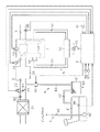
図1に、本発明が適用される車載内燃機関(以下、内燃機関1)の概略構成を示す。尚、車両は駆動源として内燃機関1とモータとを併せ備えるハイブリッドカーであり、内燃機関1は燃料としてガソリンとガソリンよりも沸点の低いエタノールとの混合燃料を使用可能なポート噴射式のエンジンである。
Hereinafter, an embodiment in which a radiator cooling fan control device according to the present invention is embodied will be described with reference to FIGS.
FIG. 1 shows a schematic configuration of an in-vehicle internal combustion engine (hereinafter, internal combustion engine 1) to which the present invention is applied. The vehicle is a hybrid car having both an
図1に示すように、内燃機関1には燃焼室11に吸気を導入するための吸気通路2と、燃焼室11から排気を排出するための排気通路3とが設けられている。
吸気通路2には、吸気上流側から順に、エアクリーナ21、スロットルバルブ22、及びサージタンク24が設けられている。また、スロットルバルブ22を開閉駆動するスロットルモータ23が設けられている。
As shown in FIG. 1, the
In the
燃料タンク41内の燃料は燃料ポンプ42により吸引されるとともに燃料供給通路43を通じて圧送されてインジェクタ44に供給される。そして、また、吸気ポートに設けられたインジェクタ44から燃焼室11に向けて燃料が噴射される。燃料タンク41、燃料ポンプ42、燃料供給通路43、及びインジェクタ44により燃料供給系4が構成される。
The fuel in the
また、内燃機関1にはインジェクタ44から噴射された燃料と吸気との混合気に点火を行なう点火プラグ12が設けられている。
車両には内燃機関1の冷却を行なうための冷却装置5が設けられている。この冷却装置5は、ウォータポンプ52から吐出された冷却水をシリンダブロック及びシリンダヘッド内に形成されたウォータジャケット53に圧送することにより内燃機関1の冷却を行なう。ウォータジャケット53から排出された冷却水は冷却水通路51を介してラジエータ54に導入される。そして、冷却水はラジエータ54内を流通する際にラジエータ54を通過する走行風との間で熱交換が行なわれることで冷却される。また車両には、ラジエータ54に対して送風する電動式の冷却ファン55が設けられている。
In addition, the
The vehicle is provided with a
内燃機関1には、燃料タンク41内に発生する蒸発燃料を吸気通路2に導入して処理する蒸発燃料処理装置6が設けられている。蒸発燃料処理装置6は、燃料成分を吸着する吸着材を有するキャニスタ61を備えている。キャニスタ61は、ベーパ通路62を介して燃料タンク41に接続されている。また、キャニスタ61には、開放通路64が接続されている。これにより、燃料タンク41からベーパ通路62を通じてキャニスタ61に導かれた気体のうちの燃料成分がキャニスタ61に吸着されて浄化される。そして、浄化された空気が開放通路64を通じて大気中に放出される。
The
更にキャニスタ61には、吸気通路2と連通されたパージ通路63が設けられている。パージ通路63の途中には電動式の制御弁65が設けられている。こうした蒸発燃料処理装置6では、制御弁65が開弁されたときに吸気通路2内の負圧によってキャニスタ61内の空気がパージ通路63を通じて吸気通路2に吸い出される。このとき、開放通路64から新気が導入されることでキャニスタ61に吸着されていた燃料成分が脱離し、新気とこの燃料成分とが混合してパージガスとなり、このパージガスが吸気通路2に導入されるようになる。このようにキャニスタ61に吸着されていた燃料成分を脱離させ、パージガスを吸気通路2に導入して燃焼処理する、いわゆるパージ制御を実行することにより、キャニスタ61の燃料成分吸着能力が回復するようになる。
Further, the
内燃機関1の各種制御、制御弁65の開度制御、及び冷却ファン55の駆動制御は電子制御装置9により行なわれる。
内燃機関1には例えば機関回転速度NEを検出する機関回転速度センサ91、吸気量GAを検出する吸気量センサ92、スロットル開度TAを検出するスロットル開度センサ93、冷却水温THWを検出する水温センサ94、排気の空燃比AFを検出する空燃比センサ95といった機関運転状態を検出する各種センサが設けられている。また、燃料タンク41内の燃料の液位Lを検出する液位センサ96や、IGスイッチ97等の各種センサが設けられている。そして、これらの各種センサは、電子制御装置9に電気的に接続されている。
Various controls of the
The
また、電子制御装置9には、アクセル操作量ACCPやブレーキ踏み込み量B、車速Vといった車両走行状態を検出する各種センサが電気的に接続されている。
電子制御装置9は、各種制御にかかる演算処理を実施する中央演算処理装置(CPU)、各種制御用のプログラムやデータが記憶された読み出し専用メモリ(ROM)、演算処理の結果等を一時的に記憶するランダムアクセスメモリ(RAM)等を備えて構成されている。そして、電子制御装置9は、上記各種センサの検出信号を読み込み、各種演算処理を実行し、その結果に基づいて車両(内燃機関1、制御弁65、冷却ファン55)を統括的に制御する。
Further, the electronic control device 9 is electrically connected to various sensors for detecting a vehicle running state such as an accelerator operation amount ACCP, a brake depression amount B, and a vehicle speed V.
The electronic control unit 9 temporarily stores a central processing unit (CPU) that performs arithmetic processing related to various controls, a read-only memory (ROM) that stores various control programs and data, and results of arithmetic processing. It comprises a random access memory (RAM) for storing. The electronic control unit 9 reads the detection signals of the various sensors, executes various arithmetic processes, and comprehensively controls the vehicle (the
具体的には、電子制御装置9は、IGスイッチ97がON操作されると、スタータモータを駆動してクランキングを行なうとともに燃料噴射制御及び点火制御を開始することにより機関始動を行なう。また、IGスイッチ97がOFF操作されると、インジェクタ44からの燃料噴射を停止して機関運転を停止する。
Specifically, when the
電子制御装置9は、空燃比が理論空燃比となるように燃料噴射量を制御する空燃比フィードバック制御を行なう。
電子制御装置9は、制御弁65の開度を調節することにより吸気通路2に導入されるパージガスを調量するパージ制御を行なう。
The electronic control unit 9 performs air-fuel ratio feedback control for controlling the fuel injection amount so that the air-fuel ratio becomes the stoichiometric air-fuel ratio.
The electronic control device 9 performs purge control for adjusting the purge gas introduced into the
ここで、空燃比フィードバック制御とパージ制御との関係について説明する。空燃比フィードバック制御は、基本的に空燃比を理論空燃比近傍に保持するように、空燃比センサ95の出力に基づき燃料噴射量をフィードバック制御することにより行われる。
Here, the relationship between air-fuel ratio feedback control and purge control will be described. The air-fuel ratio feedback control is basically performed by feedback-controlling the fuel injection amount based on the output of the air-
しかしながら、パージ制御を通じて燃料成分を含むパージガスが吸気通路2に導入されているときには、インジェクタ44から噴射される燃料に加えて、パージガスに含まれる燃料が燃焼室11に供給されるようになるため、空燃比がずれるようになる。そこで、空燃比フィードバック制御では、パージ制御によりパージガスが導入されている間は、パージガスに含まれる燃料の分だけインジェクタ44から噴射する燃料噴射量を減少させる燃料噴射量の減量補正を行うようにしている。尚、パージガスに含まれる燃料の量(以下、パージ量PG)は、パージガスの流量と、機関運転中に周知の態様により学習されるパージ濃度Dとに基づき電子制御装置9により所定時間毎に算出される。そして、この算出された燃料の量に基づいて上記減量補正が行なわれる。ちなみに、本実施形態では、パージ量PGを以下の式(1)から算出するようにしている。
However, when the purge gas containing the fuel component is introduced into the
PG = GA × R × D ・・・(1)
ここで、吸気量GAに対して、吸気に含まれるパージガスの割合であるパージ割合Rを乗じることによりパージガスの流量が算出され、更にパージ濃度Dを乗じることによりパージ量PGが算出される。
PG = GA × R × D (1)
Here, the purge amount R is calculated by multiplying the intake amount GA by the purge ratio R, which is the ratio of the purge gas contained in the intake air, and the purge amount PG is calculated by further multiplying the purge concentration D.
また、電子制御装置9は、車両停止時や低速走行時のように十分な量の走行風を見込むことができない場合に、ラジエータ54を通過する空気の流量を確保すべく、冷却ファン55の駆動制御を行なう。
Further, the electronic control unit 9 drives the cooling
ところで、前述したように、機関温度が高い状態で車両が停止すると、ラジエータ54を通過する走行風がなくなり、冷却水を冷却することができなくなることで、機関温度が高温に保たれることとなる。そして、高温の機関から伝達される熱や放射される熱によって燃料供給通路43やインジェクタ44等の燃料供給系4が加熱されると、特にガソリンに比べて沸点の低いエタノールの蒸発が促進され、液体燃料中にベーパが発生する。その結果、内燃機関1を再始動した際に機関運転状態に見合った量の燃料がインジェクタ44から噴射することができない現象、所謂ベーパロック現象が生じ、機関運転が不安定になるおそれがある。
By the way, as described above, when the vehicle stops with the engine temperature being high, there is no traveling wind passing through the
そこで、本実施形態では、以下に説明する冷却ファンの駆動制御を通じて、上述した不都合の発生を抑制するようにしている。すなわち、燃料タンク41への燃料の給油が行なわれてから吸気通路2に導入された蒸発燃料量、すなわちパージ量PGを算出するとともに、この積算値(以下、パージ量積算値PGS)を算出する。そして、このパージ量積算値PGSが所定値PGSth未満のときには機関停止後に冷却ファン55を駆動する一方、パージ量積算値PGSが所定値PGSth以上であるときには機関停止後における冷却ファン55の駆動を禁止する。
Therefore, in this embodiment, the occurrence of the above-described inconvenience is suppressed through drive control of the cooling fan described below. That is, the amount of evaporated fuel introduced into the
次に、このように給油が行なわれてからのパージ量積算値PGSに応じて機関停止時における冷却ファン55の駆動を行なうか否かを決定する理由について説明する。
図2に、燃料のエタノール濃度Eと当該燃料の沸点Tbpとの関係を示す。
Next, the reason for determining whether or not to drive the cooling
FIG. 2 shows the relationship between the ethanol concentration E of the fuel and the boiling point Tbp of the fuel.
図2に示すように、エタノールの沸点(約78℃)はガソリンの沸点(本実施形態では120℃)よりも低い。すなわち、燃料のエタノール濃度Eが0%のときには燃料の沸点Tbpは120℃となる。また、燃料のエタノール濃度Eが0%から約20%(日本国内において流通する燃料のエタノール濃度Eの最大値)までの範囲においては、燃料のエタノール濃度Eが高くなるほど当該燃料の沸点Tbpは低くなり、燃料のエタノール濃度Eが20%のときには燃料の沸点Tbpは約111.5℃となる。ちなみに、燃料のエタノール濃度Eが20%よりも高い範囲においては、燃料のエタノール濃度Eが高くなるほど当該燃料の沸点Tbpは高くなる。尚、図2において、機関停止後に燃料供給系4における燃料の温度が到達可能な最高温度Tmax(本実施形態では112℃)を一点鎖線にて示す。 As shown in FIG. 2, the boiling point of ethanol (about 78 ° C.) is lower than the boiling point of gasoline (120 ° C. in this embodiment). That is, when the ethanol concentration E of the fuel is 0%, the fuel boiling point Tbp is 120 ° C. In the range where the ethanol concentration E of the fuel is from 0% to about 20% (the maximum value of the ethanol concentration E of the fuel distributed in Japan), the boiling point Tbp of the fuel decreases as the ethanol concentration E of the fuel increases. Thus, when the ethanol concentration E of the fuel is 20%, the boiling point Tbp of the fuel is about 111.5 ° C. Incidentally, in the range where the ethanol concentration E of the fuel is higher than 20%, the boiling point Tbp of the fuel becomes higher as the ethanol concentration E of the fuel becomes higher. In FIG. 2, the maximum temperature Tmax (112 ° C. in the present embodiment) at which the fuel temperature in the fuel supply system 4 can reach after the engine is stopped is indicated by a one-dot chain line.
このように、図2に示される燃料のエタノール濃度Eの範囲(0%≦E≦20%)において、燃料のエタノール濃度Eが所定濃度Eth以上のときには、燃料の沸点Tbpが上記到達可能な最高温度Tmaxを下回るようになる。この場合、機関停止後において燃料供給系4における燃料の温度が当該燃料の沸点Tbpを上回る状況が生じ得るため、当該燃料に含まれるエタノールが蒸発するおそれがある。 Thus, in the range of the ethanol concentration E of the fuel shown in FIG. 2 (0% ≦ E ≦ 20%), when the ethanol concentration E of the fuel is equal to or higher than the predetermined concentration Eth, the boiling point Tbp of the fuel is the highest that can be reached. The temperature falls below Tmax. In this case, since the temperature of the fuel in the fuel supply system 4 may exceed the boiling point Tbp of the fuel after the engine is stopped, the ethanol contained in the fuel may evaporate.
一方、燃料のエタノール濃度Eが上記所定濃度Ethよりも低いときには、燃料の沸点Tbpが上記到達可能な最高温度Tmaxを上回るようになる。この場合、機関停止後において燃料供給系4における燃料の温度が当該燃料の沸点Tbpを上回る状況が生じ得ないため、燃料に含まれるエタノールが蒸発することはない。 On the other hand, when the ethanol concentration E of the fuel is lower than the predetermined concentration Eth, the boiling point Tbp of the fuel exceeds the reachable maximum temperature Tmax. In this case, since the situation where the temperature of the fuel in the fuel supply system 4 exceeds the boiling point Tbp of the fuel cannot occur after the engine is stopped, ethanol contained in the fuel does not evaporate.
従って、燃料タンク41への給油が行なわれることによって燃料タンク41内の燃料のエタノール濃度Eが例えば20%とされた後、機関運転に伴って燃料の温度が上昇し始めると、燃料の沸点Tbp及び燃料のエタノール濃度Eは例えば図3に示すように推移する。すなわち、図3に示すように、当該給油後における機関運転の経過時間tが第1の所定時間t1となると、まずは沸点の低いエタノールが蒸発し始めることで燃料のエタノール濃度Eが徐々に低下するようになる。またこれに伴って、燃料の沸点Tbpは111.5℃から徐々に上昇するようになる。その後、第2の所定時間t2が経過すると、燃料のエタノール濃度Eが所定濃度Eth以下となり、燃料の沸点Tbpが上記到達可能な最高温度Tmax以上となる。
Accordingly, when the fuel concentration in the
ここで、燃料のエタノール濃度Eは、燃料タンク41への燃料の給油が行なわれてからの燃料タンク41内に貯留されている燃料から蒸発した燃料量と相関がある。また前述したように、燃料タンク41内に貯留されている燃料から蒸発した燃料量は、当該給油が行なわれてからのパージ量PGの積算値(以下、パージ量積算値PGS)と相関がある。よって、本実施形態では、パージ量積算値PGSに応じて機関停止時における冷却ファン55の駆動を行なうか否かを決定している。
Here, the ethanol concentration E of the fuel correlates with the amount of fuel evaporated from the fuel stored in the
次に、図4を参照して、機関停止時における冷却ファンの駆動制御の具体的な処理手順について説明する。尚、図4に示す一連の処理は、電子制御装置9への通電中において所定期間毎に繰り返し実行される。 Next, with reference to FIG. 4, a specific processing procedure of cooling fan drive control when the engine is stopped will be described. Note that the series of processes shown in FIG. 4 is repeatedly executed at predetermined intervals during energization of the electronic control unit 9.
図4に示すように、この一連の処理では、まず、ステップS1において、機関停止指令が出力されたか否かを判断する。ここでは、IGスイッチ97のOFF操作が検出されているときに機関停止指令が出力されたと判断する。そして、機関停止指令が出力されたと判断されない場合には(ステップS1:「NO」)、冷却ファンの駆動制御の実行タイミングではないとして、この一連の処理を一旦終了する。
As shown in FIG. 4, in this series of processing, first, in step S1, it is determined whether an engine stop command has been output. Here, it is determined that the engine stop command is output when the OFF operation of the
一方、ステップS1において、機関停止指令が出力されたと判断した場合には(ステップS1:「YES」)、次に、ステップS2に進み、次に、駆動禁止フラグFが「OFF」であるか否かを判断する。 On the other hand, if it is determined in step S1 that an engine stop command has been output (step S1: “YES”), the process proceeds to step S2, and then whether or not the drive prohibition flag F is “OFF”. Determine whether.
ここで、図5を参照して駆動禁止フラグの設定処理手順について説明する。尚、図5に示す一連の処理は、機関運転中において所定期間毎に繰り返し実行される。また、駆動禁止フラグFは最初、「OFF」に設定されている。 Here, the procedure for setting the drive prohibition flag will be described with reference to FIG. The series of processes shown in FIG. 5 is repeatedly executed at predetermined intervals during engine operation. The drive prohibition flag F is initially set to “OFF”.
図5に示すように、この一連の処理では、まず、ステップS11において、直前に燃料給油が行なわれたか否かを判断する。ここでは、液位センサ96により検出された燃料タンク41内の燃料の液位Lが、前回の制御周期において検出された値よりも所定値以上、上昇していないときには、直前に燃料の給油が行なわれていない旨判断する。この結果、直前に燃料給油が行なわれた旨判断した場合には(ステップS11:「NO」)、次に、ステップS12に進み、当該給油により燃料のエタノール濃度Eが上昇した可能性があるとして、パージ量積算値PGSに「0」を設定して、この一連の処理を一旦終了する。この場合、機関停止時に冷却ファン55を駆動する必要があるとして、駆動禁止フラグFは「OFF」のまま変更されない。
As shown in FIG. 5, in this series of processing, first, in step S11, it is determined whether fuel refueling has been performed immediately before. Here, when the liquid level L of the fuel in the
一方、ステップS11において、直前に燃料給油が行なわれていない旨判断した場合には(ステップS11:「YES」)、次に、ステップS13に進み、パージ量積算値PGSを更新する。具体的には、前回の制御周期から今回の制御周期までの間に吸気通路2に導入されたパージ量PGを算出するとともに、同パージ量PGを、前回の制御周期におけるパージ量積算値PGSに加算することにより新たなパージ量積算値PGSとする。
On the other hand, if it is determined in step S11 that the fuel supply has not been performed immediately before (step S11: “YES”), the process proceeds to step S13, where the purge amount integrated value PGS is updated. Specifically, the purge amount PG introduced into the
こうしてパージ量積算値PGSを更新すると、次に、ステップS14に進み、ステップS13において更新されたパージ量積算値PGSが所定値PGSth以上であるか否かを判断する。ここで、所定値PGSthは、実験やシミュレーションを通じて予め設定された値であり、以下のように設定されている。すなわち、所定値PGSthは、燃料タンク41内にエタノール濃度Eが20%である燃料が満たされている状態からエタノールの蒸発が進むことにより当該燃料のエタノール濃度Eが上記所定濃度Ethとなったときのパージ量積算値PGSに設定されている。
When the purge amount integrated value PGS is updated in this way, the process proceeds to step S14, and it is determined whether or not the purge amount integrated value PGS updated in step S13 is equal to or greater than a predetermined value PGSth. Here, the predetermined value PGSth is a value set in advance through experiments and simulations, and is set as follows. That is, the predetermined value PGSth is obtained when the ethanol concentration E of the fuel reaches the predetermined concentration Eth as the ethanol evaporates from a state where the
上記ステップS14において、パージ量積算値PGSが上記所定値PGSth以上である場合には(ステップS14:「YES」)、燃料タンク41内の燃料から多くのエタノールが蒸発したことで当該燃料のエタノール濃度Eが上記所定濃度Eth以下となったとして、次に、ステップS15に進み、駆動禁止フラグFを「ON」に設定して、この一連の処理を一旦終了する。
If the purge amount integrated value PGS is greater than or equal to the predetermined value PGSth in step S14 (step S14: “YES”), a large amount of ethanol has evaporated from the fuel in the
一方、ステップS14においてパージ量積算値PGSが上記所定値PGSth未満である場合には(ステップS14:「NO」)、燃料タンク41内の燃料からエタノールがそれほど蒸発しておらず当該燃料のエタノール濃度Eが上記所定濃度Ethよりも高いとして、この一連の処理を一旦終了する。この場合、機関停止時に冷却ファン55を駆動する必要があるとして、駆動禁止フラグFは「OFF」のまま変更されない。
On the other hand, if the purge amount integrated value PGS is less than the predetermined value PGSth in step S14 (step S14: "NO"), ethanol has not evaporated so much from the fuel in the
先の図4に示すように、ステップS2において、駆動禁止フラグFが「OFF」である場合には、次に、ステップS3に進み、冷却ファン55を駆動する。そして、次に、ステップS5に進み、冷却ファン55の駆動を停止するための駆動停止条件が成立した否かを判断する。具体的には、冷却ファン55の駆動を開始してからの経過時間が所定時間となった場合に駆動停止条件が成立していると判断する。ここで、駆動停止条件が成立していない場合には(ステップS5:「NO」)、冷却ファン55の駆動を継続して、この一連の処理を一旦終了する。
As shown in FIG. 4, when the drive prohibition flag F is “OFF” in step S2, the process proceeds to step S3, and the cooling
一方、ステップS5において、駆動停止条件が成立している場合には(ステップS5:「YES」)、次に、ステップS6に進み、冷却ファン55の駆動を停止して、この一連の処理を一旦終了する。
On the other hand, if the drive stop condition is satisfied in step S5 (step S5: “YES”), then the process proceeds to step S6, the drive of the cooling
また、ステップS2において、駆動禁止フラグFが「OFF」である場合には、次に、ステップS4に進み、冷却ファン55の駆動を禁止して、この一連の処理を一旦終了する。
If the drive prohibition flag F is “OFF” in step S2, the process proceeds to step S4, the drive of the cooling
次に本実施形態の作用を説明する。
本実施形態では、車両停止時や低速走行時のように十分な量の走行風を見込むことができない場合に、冷却ファン55が駆動されることによってラジエータ54を通過する空気の流量が確保される。
Next, the operation of this embodiment will be described.
In the present embodiment, when a sufficient amount of traveling wind cannot be expected, such as when the vehicle is stopped or traveling at a low speed, the cooling
また、燃料タンク41への給油が行なわれてからのパージ量積算値PGSが算出される。そして、このパージ量積算値PGSが所定値PGSth未満のときには、当該燃料のエタノール濃度Eが所定濃度Ethよりも高い可能性があり、機関停止後において燃料供給系4における燃料の温度が当該燃料の沸点Tbpを上回るおそれがあり、当該液体燃料中にベーパが発生するおそれがあるとして機関停止後に冷却ファン55が駆動される。これにより、液体燃料中にベーパが発生することを抑制することができ、その後の機関再始動時においてベーパロック現象が生じて燃料噴射を行なうことができなくなることを好適に抑制することができる。
Further, the purge amount integrated value PGS after the
一方、パージ量積算値PGSが所定値PGSth以上であるときには当該燃料のエタノール濃度Eが所定濃度Eth以下であり、機関停止後において燃料供給系4における燃料の温度が到達可能な最高温度Tmaxとなったとしても当該燃料の沸点Tbpを上回ることはなく液体燃料中にベーパが発生するおそれがないとして冷却ファン55の駆動が禁止される。これにより、液体燃料中にベーパが発生しないときまで冷却ファン55が無駄に駆動されることを好適に抑制することができる。このため、冷却ファン55の駆動に伴うバッテリの電力消費を好適に抑制することができる。
On the other hand, when the purge amount integrated value PGS is equal to or higher than the predetermined value PGSth, the ethanol concentration E of the fuel is equal to or lower than the predetermined concentration Eth, and becomes the maximum temperature Tmax at which the fuel temperature in the fuel supply system 4 can be reached after the engine is stopped. Even if it does not exceed the boiling point Tbp of the fuel, the driving of the cooling
尚、電子制御装置9が本発明に係るラジエータの冷却ファン制御装置に相当する。
以上説明した本実施形態に係るラジエータの冷却ファン制御装置によれば、以下に示す作用効果が得られるようになる。
The electronic control device 9 corresponds to a radiator cooling fan control device according to the present invention.
According to the cooling fan control device for a radiator according to the present embodiment described above, the following operational effects can be obtained.
(1)内燃機関1は燃料タンク41内の蒸発燃料を吸気通路2に導入して処理する蒸発燃料処理装置6を備える。電子制御装置9は、エタノールと当該エタノールよりも沸点の高いガソリンとが混合された燃料を使用可能な内燃機関1に適用され、当該内燃機関1のラジエータ54に設けられた電動式の冷却ファン55の駆動を制御する。電子制御装置9は、燃料タンク41への燃料の給油が行なわれてから吸気通路2に導入された蒸発燃料量の積算値であるパージ量積算値PGSを算出する。そして、電子制御装置9は、パージ量積算値PGSが所定値PGSth未満のときには当該燃料のエタノール濃度Eが所定濃度Ethよりも高い可能性があるとして機関停止後に冷却ファン55を駆動する。一方、電子制御装置9は、パージ量積算値PGSが所定値PGSth以上であるときには当該燃料のエタノール濃度Eが所定濃度Eth以下であるとして機関停止後における冷却ファン55の駆動を禁止する。こうした構成によれば、再始動時における機関運転の不安定化を好適に抑制しつつ、冷却ファン55の駆動に伴うバッテリの電力消費を的確に抑制することができる。
(1) The
尚、本発明に係るラジエータの冷却ファン制御装置は、上記実施形態にて例示した構成に限定されるものではなく、これを適宜変更した例えば次のような形態として実施することもできる。 The radiator cooling fan control device according to the present invention is not limited to the configuration exemplified in the above-described embodiment, and can be implemented as, for example, the following forms appropriately modified.
・上記実施形態及びその変形例では、燃料に含まれるアルコールの一例としてエタノールについて例示したが、本発明に係るアルコールはこれに限定されるものではなく、ガソリンよりも沸点の低いものであれば他のアルコールに置換することができる。 In the above embodiment and its modifications, ethanol is exemplified as an example of an alcohol contained in fuel, but the alcohol according to the present invention is not limited to this, and any other alcohol having a lower boiling point than gasoline Can be substituted with alcohol.
・上記実施形態では、給油が行なわれてからの燃料タンク41内の蒸発燃料量をパージ量積算値PGSに基づき把握するようにしたが、本発明はこれに限定されるものではない。パージ量積算値PGSに代えて、或いはパージ量積算値PGSに加えて、給油が行なわれてからの以下のパラメータの推移に基づいて、給油が行なわれてからの燃料タンク41内の蒸発燃料量、すなわち燃料のエタノール濃度Eを把握するようにしてもよい。こうしたパラメータとしては、外気温、機関運転継続時間、及び車両走行距離の少なくとも一つを挙げることができる。
In the above embodiment, the amount of evaporated fuel in the
・上記実施形態及びその変形例では、給油が行なわれてからの燃料タンク41内の蒸発燃料量から燃料のエタノール濃度Eを把握するようにしているが、これに代えて、例えば空燃比センサ95により検出される排気の空燃比AFに基づき燃料のエタノール濃度Eを周知の態様にて推定するようにしてもよい。この場合、空燃比センサ95及び電子制御装置9が本発明に係る推定手段に相当する。
In the above-described embodiment and its modification, the ethanol concentration E of the fuel is grasped from the amount of evaporated fuel in the
・上記実施形態及びその変形例に代えて、燃料タンク41への燃料の給油が行なわれてから所定期間が経過するまでは機関停止後に冷却ファン55を駆動する一方、当該給油が行なわれてから所定期間が経過した後は機関停止後における冷却ファン55の駆動を禁止するようにしてもよい。この場合、例えば、給油が行なわれたときに、燃料タンク41内にエタノール濃度Eが20%である燃料が満たされている状態であると仮定するとともに、当該給油から、燃料のエタノール濃度Eが所定濃度Eth以下となるまでに要する時間の最大値を上記所定期間に設定することができる。これにより、再始動時における機関運転の不安定化を確実に抑制することができるようになる。
In place of the above embodiment and its modification, the cooling
ただし、実際には、当該給油からの経過時間が同一であっても、機関運転状態の推移、外気温の推移、或いは車両走行距離によって燃料のエタノール濃度Eの低下態様は異なるものとなる。そこで、上記所定期間をこれらのパラメータの推移の少なくとも一つに基づいて可変設定するようにすることが望ましい。 However, in practice, even if the elapsed time from the refueling is the same, the mode of decrease in the ethanol concentration E of the fuel differs depending on the transition of the engine operating state, the transition of the outside air temperature, or the vehicle travel distance. Therefore, it is desirable to variably set the predetermined period based on at least one of the transitions of these parameters.
・上記実施形態によるように、燃料のエタノール濃度Eが所定濃度Eth以下であるときには機関停止後における冷却ファン55の駆動を禁止することがバッテリの電力消費を確実に抑制する上では望ましい。しかしながら、本発明はこれに限定されるものではなく、燃料のエタノール濃度Eが所定濃度Eth以下であるときにはそうでないときに比べて冷却ファン55への通電量を低減するなどしてその駆動を制限するようにしてもよい。
As described in the above embodiment, when the ethanol concentration E of the fuel is equal to or less than the predetermined concentration Eth, it is desirable to prohibit the driving of the cooling
・上記実施形態及びその変形例では、燃料のエタノール濃度Eを間接的に把握するようにしたが、これに代えて、燃料のエタノール濃度Eを直接的に検出するセンサを備えるとともに、当該センサの検出結果に応じて冷却ファン55の駆動態様を設定するようにしてもよい。
In the above-described embodiment and its modification, the ethanol concentration E of the fuel is indirectly grasped, but instead of this, a sensor that directly detects the ethanol concentration E of the fuel is provided, and The driving mode of the cooling
1…内燃機関、2…吸気通路、3…排気通路、4…燃料供給系、5…冷却装置、6…蒸発燃料処理装置、9…電子制御装置、11…燃焼室、12…点火プラグ、21…エアクリーナ、22…スロットルバルブ、23…スロットルモータ、24…サージタンク、41…燃料タンク、42…燃料ポンプ、43…燃料供給通路、44…インジェクタ、51…冷却水通路、52…ウォータポンプ、53…ウォータジャケット、54…ラジエータ、55…冷却ファン、61…キャニスタ、62…ベーパ通路、63…パージ通路、64…開放通路、65…制御弁、91…機関回転速度センサ、92…吸気量センサ、93…スロットル開度センサ、94…空燃比センサ、95…水温センサ、96…液位センサ、97…IGスイッチ。
DESCRIPTION OF
Claims (6)
燃料タンクへの燃料の給油が行なわれてからの燃料タンク内における燃料の蒸発量が所定量未満のときには当該燃料のアルコール濃度が所定濃度よりも高いとして機関停止後に冷却ファンを駆動する一方、当該給油が行なわれてからの燃料タンク内における燃料の蒸発量が前記所定量以上であるときには当該燃料のアルコール濃度が前記所定濃度以下であるとして機関停止後における冷却ファンの駆動を制限する
ことを特徴とするラジエータの冷却ファン制御装置。 Cooling fan control of a radiator that is applied to an internal combustion engine capable of using a fuel in which gasoline and alcohol having a boiling point lower than that of the gasoline are used, and controls driving of an electric cooling fan provided in the radiator of the internal combustion engine A device,
When the amount of fuel evaporation in the fuel tank after the fuel supply to the fuel tank is less than a predetermined amount, the alcohol concentration of the fuel is higher than the predetermined concentration and the cooling fan is driven after the engine is stopped, When the evaporation amount of fuel in the fuel tank after refueling is equal to or greater than the predetermined amount, the driving of the cooling fan after the engine is stopped is limited on the assumption that the alcohol concentration of the fuel is equal to or lower than the predetermined concentration. Radiator cooling fan control device.
当該燃料のアルコール濃度が前記所定濃度以下であるときには機関停止後における冷却ファンの駆動を禁止する
ことを特徴とするラジエータの冷却ファン制御装置。 In the radiator cooling fan control device according to claim 1,
A cooling fan control device for a radiator, wherein when the alcohol concentration of the fuel is equal to or lower than the predetermined concentration, driving of the cooling fan is prohibited after the engine is stopped.
内燃機関は燃料タンク内の蒸発燃料を吸気通路に導入して処理する蒸発燃料処理装置を備えるものであって、
当該給油が行なわれてから吸気通路に導入された蒸発燃料量の積算値であるパージ量積算値を算出するとともに、前記パージ量積算値が所定値未満のときには当該燃料のアルコール濃度が前記所定濃度よりも高いとして機関停止後に冷却ファンを駆動する一方、前記パージ量積算値が前記所定値以上であるときには当該燃料のアルコール濃度が前記所定濃度以下であるとして機関停止後における冷却ファンの駆動を制限する
ことを特徴とするラジエータの冷却ファン制御装置。 In the radiator cooling fan control device according to claim 1 or 2,
The internal combustion engine includes an evaporated fuel processing device that introduces and processes the evaporated fuel in the fuel tank into the intake passage,
A purge amount integrated value that is an integrated value of the evaporated fuel amount introduced into the intake passage after the refueling is calculated is calculated, and when the purge amount integrated value is less than a predetermined value, the alcohol concentration of the fuel is the predetermined concentration. The cooling fan is driven after the engine is stopped, and when the purge amount integrated value is not less than the predetermined value, the alcohol concentration of the fuel is not more than the predetermined concentration, and the driving of the cooling fan after the engine is stopped is limited. A cooling fan control device for a radiator.
燃料のアルコール濃度を推定する推定手段を備え、
前記推定手段により推定された当該燃料のアルコール濃度が前記所定濃度以下である場合には、燃料タンクへの燃料の給油が行なわれてからの燃料タンク内における燃料の蒸発量にかかわらず機関停止後における冷却ファンの駆動を制限する
ことを特徴とするラジエータの冷却ファン制御装置。 In the radiator cooling fan control device according to any one of claims 1 to 3 ,
An estimation means for estimating the alcohol concentration of the fuel;
When the alcohol concentration of the fuel estimated by the estimating means is equal to or lower than the predetermined concentration, after the engine is stopped regardless of the amount of fuel evaporated in the fuel tank after the fuel is supplied to the fuel tank. A cooling fan control device for a radiator, wherein the driving of the cooling fan is limited .
燃料タンクへの燃料の給油が行なわれてからの燃料タンク内の燃料におけるアルコールの蒸発量が所定量未満のときには機関停止後に冷却ファンを駆動する一方、当該給油が行なわれてからの前記アルコールの蒸発量が前記所定量以上であるときには機関停止後における冷却ファンの駆動を制限する When the amount of alcohol evaporated in the fuel in the fuel tank after the fuel is supplied to the fuel tank is less than a predetermined amount, the cooling fan is driven after the engine is stopped, while the alcohol after the fuel is supplied When the evaporation amount is equal to or greater than the predetermined amount, the driving of the cooling fan after the engine is stopped is limited.
ことを特徴とするラジエータの冷却ファン制御装置。 A cooling fan control device for a radiator.
燃料タンクへの燃料の給油が行なわれてから所定期間が経過するまでは機関停止後に冷却ファンを駆動する一方、当該給油が行なわれてから前記所定期間が経過した後は機関停止後における冷却ファンの駆動を制限する The cooling fan is driven after the engine is stopped until the predetermined period elapses after the fuel is supplied to the fuel tank, and the cooling fan after the engine is stopped after the predetermined period elapses after the fuel supply is performed. The drive of
ことを特徴とするラジエータの冷却ファン制御装置。 A cooling fan control device for a radiator.
Priority Applications (6)
| Application Number | Priority Date | Filing Date | Title |
|---|---|---|---|
| JP2011198565A JP5655748B2 (en) | 2011-09-12 | 2011-09-12 | Radiator cooling fan controller |
| CN201280043895.6A CN103782003A (en) | 2011-09-12 | 2012-09-11 | Cooling fan control apparatus and cooling fan control method for radiator |
| EP12778388.4A EP2756177A1 (en) | 2011-09-12 | 2012-09-11 | Cooling fan control apparatus and cooling fan control method for radiator |
| PCT/IB2012/001757 WO2013038251A1 (en) | 2011-09-12 | 2012-09-11 | Cooling fan control apparatus and cooling fan control method for radiator |
| US14/343,864 US20140224468A1 (en) | 2011-09-12 | 2012-09-11 | Cooling fan control apparatus and cooling fan control method for radiator |
| IN429MUN2014 IN2014MN00429A (en) | 2011-09-12 | 2014-03-11 |
Applications Claiming Priority (1)
| Application Number | Priority Date | Filing Date | Title |
|---|---|---|---|
| JP2011198565A JP5655748B2 (en) | 2011-09-12 | 2011-09-12 | Radiator cooling fan controller |
Publications (3)
| Publication Number | Publication Date |
|---|---|
| JP2013060833A JP2013060833A (en) | 2013-04-04 |
| JP2013060833A5 JP2013060833A5 (en) | 2014-02-13 |
| JP5655748B2 true JP5655748B2 (en) | 2015-01-21 |
Family
ID=47076270
Family Applications (1)
| Application Number | Title | Priority Date | Filing Date |
|---|---|---|---|
| JP2011198565A Expired - Fee Related JP5655748B2 (en) | 2011-09-12 | 2011-09-12 | Radiator cooling fan controller |
Country Status (6)
| Country | Link |
|---|---|
| US (1) | US20140224468A1 (en) |
| EP (1) | EP2756177A1 (en) |
| JP (1) | JP5655748B2 (en) |
| CN (1) | CN103782003A (en) |
| IN (1) | IN2014MN00429A (en) |
| WO (1) | WO2013038251A1 (en) |
Families Citing this family (23)
| Publication number | Priority date | Publication date | Assignee | Title |
|---|---|---|---|---|
| JP5864460B2 (en) * | 2013-03-22 | 2016-02-17 | 株式会社ユニバーサルエンターテインメント | Game machine |
| JP5925719B2 (en) * | 2013-03-22 | 2016-05-25 | 株式会社ユニバーサルエンターテインメント | Game machine |
| JP5864458B2 (en) * | 2013-03-22 | 2016-02-17 | 株式会社ユニバーサルエンターテインメント | Game machine |
| JP2014183981A (en) * | 2013-03-22 | 2014-10-02 | Universal Entertainment Corp | Game machine |
| JP5918713B2 (en) * | 2013-03-22 | 2016-05-18 | 株式会社ユニバーサルエンターテインメント | Game machine |
| JP5918712B2 (en) * | 2013-03-22 | 2016-05-18 | 株式会社ユニバーサルエンターテインメント | Game machine |
| JP5864461B2 (en) * | 2013-03-22 | 2016-02-17 | 株式会社ユニバーサルエンターテインメント | Game machine |
| JP5925720B2 (en) * | 2013-03-22 | 2016-05-25 | 株式会社ユニバーサルエンターテインメント | Game machine |
| JP5864462B2 (en) * | 2013-03-22 | 2016-02-17 | 株式会社ユニバーサルエンターテインメント | Game machine |
| JP2014204855A (en) * | 2013-04-12 | 2014-10-30 | 株式会社ユニバーサルエンターテインメント | Game machine |
| JP2014204853A (en) * | 2013-04-12 | 2014-10-30 | 株式会社ユニバーサルエンターテインメント | Game machine |
| JP2014204859A (en) * | 2013-04-12 | 2014-10-30 | 株式会社ユニバーサルエンターテインメント | Game machine |
| JP2014204852A (en) * | 2013-04-12 | 2014-10-30 | 株式会社ユニバーサルエンターテインメント | Game machine |
| JP2014204856A (en) * | 2013-04-12 | 2014-10-30 | 株式会社ユニバーサルエンターテインメント | Game machine |
| JP2014204858A (en) * | 2013-04-12 | 2014-10-30 | 株式会社ユニバーサルエンターテインメント | Game machine |
| US9605583B2 (en) | 2015-03-06 | 2017-03-28 | Deere & Company | Fan control system and method |
| US9752492B2 (en) | 2015-03-06 | 2017-09-05 | Deere & Company | Fan control system and method |
| US9957874B2 (en) * | 2015-06-30 | 2018-05-01 | Ford Global Technologies, Llc | Engine cooling fan operation during hot soak |
| JP6210105B2 (en) * | 2015-11-04 | 2017-10-11 | トヨタ自動車株式会社 | Battery device |
| FR3050486B1 (en) * | 2016-04-25 | 2018-05-04 | Continental Automotive France | METHOD FOR LIMITING THE FUEL LEAKAGE OF AN INJECTOR AFTER THE MOTOR STOPPING BY FORCE COOLING OF THE INJECTION RAIL |
| CN110362130B (en) * | 2019-08-21 | 2022-02-11 | 昂纳信息技术(深圳)有限公司 | Drive control method of temperature control system |
| CN114575983B (en) * | 2020-12-02 | 2023-02-24 | 郑州宇通客车股份有限公司 | Power control method and device for engine cooling fan |
| WO2023084747A1 (en) * | 2021-11-12 | 2023-05-19 | 本田技研工業株式会社 | Internal combustion engine and method for controlling internal combustion engine |
Family Cites Families (9)
| Publication number | Priority date | Publication date | Assignee | Title |
|---|---|---|---|---|
| JPS5731557U (en) * | 1980-07-30 | 1982-02-19 | ||
| US4945885A (en) * | 1989-06-16 | 1990-08-07 | General Motors Corporation | Multi-fuel engine control with canister purge |
| JP2929709B2 (en) * | 1990-11-20 | 1999-08-03 | 三菱自動車工業株式会社 | Engine cooling device |
| US5144916A (en) * | 1990-11-19 | 1992-09-08 | Mitsubishi Jidosho Kogyo Kabushiki Kaisha | Vehicular engine cooling apparatus |
| JP3082445B2 (en) * | 1992-07-14 | 2000-08-28 | 日産自動車株式会社 | Multi-fuel engine cooling system |
| JP4534866B2 (en) * | 2005-05-19 | 2010-09-01 | トヨタ自動車株式会社 | Engine control device |
| DE102007026948A1 (en) * | 2007-06-12 | 2008-09-11 | Vdo Automotive Ag | Fuel ethanol content determining method for internal combustion engine of motor vehicle i.e. flexible fuel vehicle, involves determining ethanol content of fuel depending on determined loading degree of activated carbon filter |
| JP4877174B2 (en) * | 2007-09-21 | 2012-02-15 | トヨタ自動車株式会社 | Radiator cooling fan controller |
| JP4872970B2 (en) | 2008-06-18 | 2012-02-08 | トヨタ自動車株式会社 | Fuel injection device for internal combustion engine |
-
2011
- 2011-09-12 JP JP2011198565A patent/JP5655748B2/en not_active Expired - Fee Related
-
2012
- 2012-09-11 EP EP12778388.4A patent/EP2756177A1/en not_active Withdrawn
- 2012-09-11 US US14/343,864 patent/US20140224468A1/en not_active Abandoned
- 2012-09-11 CN CN201280043895.6A patent/CN103782003A/en active Pending
- 2012-09-11 WO PCT/IB2012/001757 patent/WO2013038251A1/en active Application Filing
-
2014
- 2014-03-11 IN IN429MUN2014 patent/IN2014MN00429A/en unknown
Also Published As
| Publication number | Publication date |
|---|---|
| EP2756177A1 (en) | 2014-07-23 |
| US20140224468A1 (en) | 2014-08-14 |
| CN103782003A (en) | 2014-05-07 |
| WO2013038251A1 (en) | 2013-03-21 |
| JP2013060833A (en) | 2013-04-04 |
| IN2014MN00429A (en) | 2015-06-19 |
Similar Documents
| Publication | Publication Date | Title |
|---|---|---|
| JP5655748B2 (en) | Radiator cooling fan controller | |
| JP5035392B2 (en) | Control device for internal combustion engine | |
| US8746211B2 (en) | Control apparatus and control method for internal combustion engine | |
| JP2011252466A (en) | Purge device for purging internal combustion engine during idle stop | |
| JP2008232007A (en) | Start control device of internal combustion engine | |
| JP2007210536A (en) | Controller for hybrid electric vehicle | |
| JP2011220114A (en) | Control device of internal combustion engine | |
| JP2010116154A (en) | Control device of vehicle | |
| JP4715632B2 (en) | Evaporative fuel processing control device for internal combustion engine | |
| JP5605006B2 (en) | Control device for internal combustion engine | |
| JP2005036790A (en) | Fuel injection control device of internal combustion engine | |
| JP5831350B2 (en) | Control device for internal combustion engine | |
| JP2011220208A (en) | Control device of internal combustion engine | |
| JP2016183583A (en) | Control device of internal combustion engine | |
| JP2010180866A (en) | Fuel injection controller of internal combustion engine | |
| JP4375209B2 (en) | Evaporative fuel processing equipment | |
| JP6188357B2 (en) | Control device for internal combustion engine | |
| JP4877174B2 (en) | Radiator cooling fan controller | |
| JP5750964B2 (en) | Control device for spark-ignition gaseous fuel engine | |
| JP2008025585A (en) | Fuel nature determination apparatus | |
| JP2007285249A (en) | Engine control device | |
| JP2007239482A (en) | Control device for internal combustion engine | |
| JP6414522B2 (en) | Engine fuel supply system | |
| JP5438597B2 (en) | Evaporation feeder | |
| JP2005351120A (en) | Control device of internal combustion engine |
Legal Events
| Date | Code | Title | Description |
|---|---|---|---|
| A521 | Request for written amendment filed |
Free format text: JAPANESE INTERMEDIATE CODE: A523 Effective date: 20131225 |
|
| A621 | Written request for application examination |
Free format text: JAPANESE INTERMEDIATE CODE: A621 Effective date: 20131225 |
|
| A977 | Report on retrieval |
Free format text: JAPANESE INTERMEDIATE CODE: A971007 Effective date: 20141014 |
|
| TRDD | Decision of grant or rejection written | ||
| A01 | Written decision to grant a patent or to grant a registration (utility model) |
Free format text: JAPANESE INTERMEDIATE CODE: A01 Effective date: 20141028 |
|
| A61 | First payment of annual fees (during grant procedure) |
Free format text: JAPANESE INTERMEDIATE CODE: A61 Effective date: 20141110 |
|
| LAPS | Cancellation because of no payment of annual fees |