JP5864402B2 - Cleaning device, image forming unit, and image forming apparatus - Google Patents
Cleaning device, image forming unit, and image forming apparatus Download PDFInfo
- Publication number
- JP5864402B2 JP5864402B2 JP2012249117A JP2012249117A JP5864402B2 JP 5864402 B2 JP5864402 B2 JP 5864402B2 JP 2012249117 A JP2012249117 A JP 2012249117A JP 2012249117 A JP2012249117 A JP 2012249117A JP 5864402 B2 JP5864402 B2 JP 5864402B2
- Authority
- JP
- Japan
- Prior art keywords
- developer
- cleaning
- image carrier
- image
- wall
- Prior art date
- Legal status (The legal status is an assumption and is not a legal conclusion. Google has not performed a legal analysis and makes no representation as to the accuracy of the status listed.)
- Expired - Fee Related
Links
Images


Classifications
-
- G—PHYSICS
- G03—PHOTOGRAPHY; CINEMATOGRAPHY; ANALOGOUS TECHNIQUES USING WAVES OTHER THAN OPTICAL WAVES; ELECTROGRAPHY; HOLOGRAPHY
- G03G—ELECTROGRAPHY; ELECTROPHOTOGRAPHY; MAGNETOGRAPHY
- G03G21/00—Arrangements not provided for by groups G03G13/00 - G03G19/00, e.g. cleaning, elimination of residual charge
- G03G21/0005—Arrangements not provided for by groups G03G13/00 - G03G19/00, e.g. cleaning, elimination of residual charge for removing solid developer or debris from the electrographic recording medium
- G03G21/0011—Arrangements not provided for by groups G03G13/00 - G03G19/00, e.g. cleaning, elimination of residual charge for removing solid developer or debris from the electrographic recording medium using a blade; Details of cleaning blades, e.g. blade shape, layer forming
- G03G21/0029—Details relating to the blade support
Description
本発明は、電子写真方式の画像形成プロセスで形成される現像剤像を担持する像担持体から現像剤を除去するクリーニング装置と、このクリーニング装置を有する画像形成ユニットと、この画像形成ユニットを備える画像形成装置とに関する。 The present invention includes a cleaning device that removes a developer from an image carrier that carries a developer image formed by an electrophotographic image forming process, an image forming unit having the cleaning device, and the image forming unit. The present invention relates to an image forming apparatus.
電子写真方式の画像形成プロセスは、たとえば、複写機、ファクシミリ機器及びプリンタなどの画像形成装置で広く採用されている。電子写真方式で動作する画像形成装置は、感光体などの像担持体の表面を一様に帯電させる帯電工程と、像担持体の表面に光を照射して静電潜像を形成する露光工程と、帯電した現像剤を当該静電潜像に付着させて像担持体上に現像剤像を形成する現像工程と、この現像剤像を用紙などの記録媒体に転写させる転写工程と、転写された現像剤像を記録媒体に定着させる定着工程といった一連の工程を実行する。 An electrophotographic image forming process is widely used in image forming apparatuses such as copiers, facsimile machines, and printers. An image forming apparatus that operates in an electrophotographic system includes a charging process that uniformly charges the surface of an image carrier such as a photoconductor, and an exposure process that forms an electrostatic latent image by irradiating the surface of the image carrier with light. A developing step of attaching the charged developer to the electrostatic latent image to form a developer image on the image carrier, a transfer step of transferring the developer image to a recording medium such as paper, and the like. A series of processes such as a fixing process for fixing the developer image to the recording medium is executed.
しかしながら、転写工程では、現像剤像の全てを像担持体から記録媒体に転写させることは難しく、像担持体上に現像剤が残留することが起こりうる。このため、画像形成装置には、転写工程の後に残留した不要な現像剤を像担持体から除去するクリーニング装置が組み込まれている。この種のクリーニング装置は、たとえば、特開2006−58729号公報(特許文献1)に開示されている。 However, in the transfer process, it is difficult to transfer the entire developer image from the image carrier to the recording medium, and the developer may remain on the image carrier. For this reason, the image forming apparatus incorporates a cleaning device that removes unnecessary developer remaining after the transfer step from the image carrier. This type of cleaning device is disclosed in, for example, Japanese Patent Application Laid-Open No. 2006-58729 (Patent Document 1).
特許文献1に開示されているクリーニング装置は、転写工程後に残留した現像剤(トナー)を感光体ドラムから除去するクリーニングブレードと、当該除去された現像剤を感光体ドラムの長手方向一端付近へ向けて搬送するスパイラルと、このスパイラルを収容するハウジングをなすカートリッジフレームとを有する。特許文献1に開示されているスパイラルは、感光体ドラムの長手方向に沿って延在する回転軸を有し、この回転軸の周囲に螺旋状の凹凸部を有している。このスパイラルは、当該回転軸の周りを回転することで、感光体ドラムから除去された現像剤を攪拌しつつ感光体ドラムの長手方向一端付近へ現像剤を搬送することができる。 The cleaning device disclosed in Patent Document 1 includes a cleaning blade that removes developer (toner) remaining after the transfer process from the photosensitive drum, and the removed developer is directed toward one end in the longitudinal direction of the photosensitive drum. And a cartridge frame that forms a housing that accommodates the spiral. The spiral disclosed in Patent Document 1 has a rotation shaft extending along the longitudinal direction of the photosensitive drum, and has a spiral uneven portion around the rotation shaft. The spiral rotates around the rotation shaft, and thereby the developer can be transported to the vicinity of one end in the longitudinal direction of the photosensitive drum while stirring the developer removed from the photosensitive drum.
上記した従来のクリーニング装置では、回転するスパイラルがハウジングの内壁と摺擦することにより異音が発生するという問題がある。この異音発生を完全に防止するには、スパイラルとハウジングの内壁との間に一定の大きさの隙間を設ければよい。しかしながら、この隙間が大きすぎると、この隙間に現像剤が滞留し若しくは蓄積されるため、現像剤の搬送効率が低下するという問題が生ずる。 The conventional cleaning device described above has a problem that abnormal noise is generated when the rotating spiral rubs against the inner wall of the housing. In order to completely prevent this abnormal noise from occurring, it is only necessary to provide a gap of a certain size between the spiral and the inner wall of the housing. However, if the gap is too large, the developer stays or accumulates in the gap, which causes a problem that the transport efficiency of the developer decreases.
上記に鑑みて本発明の目的は、前記スパイラルのような回転搬送部材がハウジングの内壁と摺擦することに起因する異音発生を抑制し得るクリーニング装置、画像形成ユニット及び画像形成装置を提供することである。 In view of the above, an object of the present invention is to provide a cleaning device, an image forming unit, and an image forming apparatus capable of suppressing the generation of abnormal noise caused by the rotary conveying member such as the spiral sliding on the inner wall of the housing. That is.
本発明の第1の態様によるクリーニング装置は、電子写真方式で形成された現像剤像を担持する像担持体と、前記像担持体から記録媒体へ前記現像剤像を転写させる転写部材とを備えた画像形成装置に組み込まれるクリーニング装置であって、前記像担持体から前記記録媒体へ転写されずに前記像担持体上に残留する残留現像剤を前記像担持体から除去するクリーニング部材と、所定方向の回転軸を有し、前記回転軸の周りを回転しつつ当該除去された残留現像剤を前記所定方向へ搬送する回転搬送部材と、前記回転搬送部材を収容するハウジングとを有し、前記ハウジングは、前記回転搬送部材の外周部と対向し且つ前記回転搬送部材を部分的に被覆する内壁を有し、前記クリーニング部材を支持する支持部材と、前記回転搬送部材の外周部と対向し且つ前記回転搬送部材を部分的に被覆する内壁を有する保護部材とを含み、前記保護部材は、フィラーが添加されていない樹脂成形材料により形成されており、前記ハウジングは、前記クリーニング部材の先端部の近傍で前記像担持体の表面を向いた開口部を有し、前記支持部材の前記内壁の端部から前記保護部材の前記内壁までの垂線であって、前記保護部材の前記内壁の前記垂線の長さを前記開口部の径とした場合、前記開口部の径は、前記回転搬送部材の外径よりも小さいことを特徴とする。 A cleaning device according to a first aspect of the present invention includes an image carrier that carries a developer image formed by electrophotography, and a transfer member that transfers the developer image from the image carrier to a recording medium. A cleaning device incorporated in the image forming apparatus, the cleaning member removing residual developer remaining on the image carrier without being transferred from the image carrier to the recording medium, and a predetermined member A rotating transport member that has a rotating shaft in a direction, and that rotates around the rotating shaft and transports the removed residual developer in the predetermined direction, and a housing that houses the rotating transport member, The housing has an inner wall facing the outer peripheral portion of the rotary transport member and partially covering the rotary transport member, a support member that supports the cleaning member, and an outer periphery of the rotary transport member And a protection member having opposed and inner walls for covering the rotary conveying member partially with the protective member is formed by a resin molding material filler is not added, the housing, the cleaning member An opening that faces the surface of the image carrier in the vicinity of the front end of the protective member, and is a perpendicular line from an end of the inner wall of the support member to the inner wall of the protective member, and the inner wall of the protective member When the length of the perpendicular is the diameter of the opening, the diameter of the opening is smaller than the outer diameter of the rotary conveying member.
本発明の第2の態様による画像形成ユニットは、現像剤像を記録媒体へ転写させる転写部材を備えた画像形成装置に組み込まれる画像形成ユニットであって、現像剤収容部と、電子写真方式で形成された現像剤像を担持する像担持体と、前記現像剤収容部から供給された現像剤を担持し、前記像担持体上に前記現像剤像を形成する現像剤担持体と、前記第1の態様によるクリーニング装置とを有することを特徴とする。 An image forming unit according to a second aspect of the present invention is an image forming unit incorporated in an image forming apparatus including a transfer member that transfers a developer image to a recording medium, and includes a developer container and an electrophotographic system. an image bearing member for bearing the formed developer image, the carries developer supplied from the developer accommodating portion, a developer carrying member for forming the developer image before Kizo bearing member, wherein And a cleaning device according to the first aspect.
本発明の第3の態様による画像形成装置は、現像剤収容部と、電子写真方式で形成された現像剤像を担持する像担持体と、前記現像剤収容部から供給された現像剤を担持し、前記像担持体上に前記現像剤像を形成する現像剤担持体と、前記現像剤像を前記像担持体から記録媒体へ転写させる転写部材と、前記第1の態様によるクリーニング装置とを有することを特徴とする。 An image forming apparatus according to a third aspect of the present invention includes a developer container, an image carrier that supports a developer image formed by an electrophotographic method, and a developer that is supplied from the developer container. and, before a developer carrying member for forming the developer image onto the Kizo bearing member, a transfer member for transferring the developer image to the recording medium from said image bearing member, a cleaning device according to the first aspect It is characterized by having.
本発明によれば、回転搬送部材を収容するハウジングは、クリーニング部材を支持する支持部材と回転搬送部材を被覆する保護部材とを含む。この保護部材の剛性は支持部材の剛性よりも低いため、回転する回転搬送部材が保護部材と摺擦しても異音発生を抑制することができる。しかも、支持部材は、保護部材よりも高い剛性を有するのでクリーニング部材を安定的に支持することができる。 According to the present invention, the housing that accommodates the rotation conveyance member includes the support member that supports the cleaning member and the protection member that covers the rotation conveyance member. Since the rigidity of the protection member is lower than the rigidity of the support member, the generation of abnormal noise can be suppressed even if the rotating rotary conveyance member slides on the protection member. Moreover, since the support member has higher rigidity than the protection member, the cleaning member can be stably supported.
以下、本発明に係る種々の実施の形態について図面を参照しつつ説明する。 Hereinafter, various embodiments according to the present invention will be described with reference to the drawings.
実施の形態1.
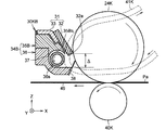
図1は、本発明に係る実施の形態1の画像形成装置1の構成を概略的に示す図である。図1に示されるように、画像形成装置1は、筐体10の中に、ブラック(K)、イエロー(Y)、マゼンタ(M)及びシアン(C)の現像剤像をそれぞれ生成する画像形成ユニット20K,20Y,20M,20Cと、被転写材である記録媒体Paを収容するトレイ11と、このトレイ11から記録媒体Paを取り出すローラ12と、トレイ11から取り出された記録媒体Paを1枚ずつ送り出すホッピングローラ13と、ホッピングローラ13から送り出された記録媒体Paを画像形成ユニット20Kへ向けて搬送する搬送ローラ15A,15B,16A,16Bと、記録媒体Paを載せて搬送する転写ベルト49と、画像形成ユニット20K,20Y,20M,20Cで形成された現像剤像を記録媒体Paに転写させる転写ローラ40K,40Y,40M,40Cと、定着器60とを備えている。
Embodiment 1 FIG.
FIG. 1 is a diagram schematically showing a configuration of an image forming apparatus 1 according to the first embodiment of the present invention. As shown in FIG. 1, the image forming apparatus 1 forms an image formation for generating black (K), yellow (Y), magenta (M), and cyan (C) developer images in a
また、画像形成装置1は、転写ベルト49を駆動する駆動ローラ47,48を備えている。転写ベルト49は、駆動ローラ47,48の外周部に張架された無端の弾性ベルトである。転写ベルト49の構成材料としては、たとえば、ポリウレタンゴムが挙げられる。駆動ローラ47,48の各々が反時計周りに回転することにより、転写ベルト49を循環的に動かすことができる。
Further, the image forming apparatus 1 includes
トレイ11は、複数枚の記録媒体Paを積層状態で収容する機能を有し、画像形成装置30のフレームに着脱自在に装着されている。記録媒体Paとしては、たとえば、用紙、プラスチックフィルム、合成紙若しくは布などのシート状の媒体が挙げられる。
The
画像形成ユニット20K,20Y,20M,20Cは、転写ベルト49上で記録媒体Paの搬送方向(−X軸方向)に沿って一列に配列されている。このため、転写ベルト49上の記録媒体Paは、画像形成ユニット20K,20Y,20M,20Cの直下をこの順番で通過する。転写ローラ40K,40Y,40M,40Cは、転写ベルト49を介して画像形成ユニット20K,20Y,20M,20Cとそれぞれ対向する位置に配置されている。
The
ブラックの現像剤像を形成する画像形成ユニット20Kは、現像剤カートリッジ21K、感光体ドラム24K、帯電ローラ25K、LEDヘッド26K、供給ローラ27K、現像ローラ28K及び層形成ブレード29Kを有する。現像剤カートリッジ21Kは、画像形成ユニット20Kの本体部に着脱自在に装着されている。この現像剤カートリッジ21Kは、未使用のブラックの現像剤を収容する現像剤収容部22Kと、後述するように記録媒体Paに転写されずに回収された残留現像剤を収容する廃現像剤収容部23Kとを含む。現像剤収容部22Kは、その下部に形成された供給口から供給ローラ27Kに現像剤を供給することができる。
The
現像剤としては、たとえば、粉砕法により製造された粉砕トナーを使用すればよい。粉砕トナーの製造工程は、たとえば、結着樹脂,着色剤,離型剤及び帯電制御剤などからなるトナー原料を溶融混練し冷却して溶融混練物を生成する工程と、当該溶融混錬物を粉砕し分級することによって平均粒径が数μmのトナー母粒子を生成する工程と、当該トナー母粒子に疎水性シリカなどの外添剤を添加して非磁性一成分の現像剤を生成する工程とで構成される。結着樹脂としては、たとえば、ガラス転移温度が約40℃のポリエステル樹脂を使用することができる。 As the developer, for example, a pulverized toner manufactured by a pulverization method may be used. The pulverized toner manufacturing process includes, for example, a step of melt kneading and cooling a toner raw material composed of a binder resin, a colorant, a release agent, a charge control agent, and the like to form a melt kneaded product, A step of generating toner base particles having an average particle size of several μm by pulverization and classification, and a step of generating a non-magnetic one-component developer by adding an external additive such as hydrophobic silica to the toner base particles. It consists of. As the binder resin, for example, a polyester resin having a glass transition temperature of about 40 ° C. can be used.
像担持体としての感光体ドラム24Kは、図1のY軸方向(図面に垂直な方向)を長手方向とする円筒形状を有し、たとえば、アルミニウムなどの金属パイプ(導電性基体)と、この金属パイプの周りに形成された有機感光体(OPC:Organic Photoconductor)などの光導電層とで構成される。画像形成装置1の動作時に、感光体ドラム24Kは、回転軸の周りを時計回りに所定速度で回転する。帯電ローラ25Kは、この感光体ドラム24Kの表面に接触して感光体ドラム24Kの表面全体を一様に帯電させる。
The
露光部としてのLEDヘッド26Kは、回転する感光体ドラム24Kの表面に印刷画像に対応するパターン光を照射して静電潜像を形成する。LEDヘッド26Kは、たとえば、感光体ドラム24Kの表面に沿ってY軸方向に配列された多数のLED素子(発光ダイオード素子)と、これらLED素子を駆動するLED駆動回路と、これらLED素子の出射光を感光体ドラム24Kの表面に導くレンズアレイとで構成される。
The LED head 26K as an exposure unit irradiates the surface of the rotating
現像剤供給部材としての供給ローラ27Kは、Y軸方向を長手方向とする円筒形状を有し、自己の中心軸の周りを回転する。供給ローラ27Kは、現像剤収容部22Kから供給された現像剤を表面に担持しつつ現像ローラ28Kに供給する。現像ローラ28Kは、Y軸方向を長手方向とする円筒形状を有し、自己の中心軸の周りを反時計回りに回転しつつ、表面に付着した現像剤を搬送する。層形成ブレード29Kは、この現像ローラ28K上の現像剤を薄層化するものである。感光体ドラム24Kの表面のうち静電潜像が形成された部分が現像ローラ28Kまで到達すると、当該静電潜像と現像ローラ28Kとの電位差により、現像剤が現像ローラ28Kから感光体ドラム24K上に移動して感光体ドラム24K上に現像剤像を形成する。その後、転写部材としての転写ローラ40Kは、当該転写ローラ40Kと感光体ドラム24Kとの間にニップ(挟持)された記録媒体Pa上に、感光体ドラム24K上の現像剤像を転写させる。このとき、転写ローラ40Kに転写バイアス(電圧)が印加されるため、静電気力が働いて現像剤像を感光体ドラム24Kから記録媒体Paへ転写させることができる。
The
他の画像形成ユニット20Y,20M,20Cの各構成は、現像剤以外は、ブラック(K)の現像剤像を形成する画像形成ユニット20Kの構成と同じである。イエロー(Y)の現像剤像を形成する画像形成ユニット20Yは、現像剤カートリッジ21Y、感光体ドラム(像担持体)24Y、帯電ローラ25Y、LEDヘッド(露光部)26Y、供給ローラ27Y、現像ローラ(現像剤担持体)28Y及び層形成ブレード29Yを有する。現像剤カートリッジ21Yは、未使用のイエローの現像剤を収容する現像剤収容部22Yと、記録媒体Paに転写されずに回収された残留現像剤を収容する廃現像剤収容部23Yとを含む。上流側の画像形成ユニット20Kから供給された記録媒体Paは、画像形成ユニット20Yの感光体ドラム24Yと転写ローラ40Yとの間にニップ(挟持)される。転写ローラ(転写部材)40Yは、この記録媒体Pa上に感光体ドラム24Y上のイエローの現像剤像を転写させる。
The other configurations of the
また、マゼンタ(M)の現像剤像を形成する画像形成ユニット20Mは、現像剤カートリッジ21M、感光体ドラム(像担持体)24M、帯電ローラ25M、LEDヘッド(露光部)26M、供給ローラ27M、現像ローラ(現像剤担持体)28M及び層形成ブレード29Mを有する。現像剤カートリッジ21Mは、未使用のマゼンタの現像剤を収容する現像剤収容部22Mと、記録媒体Paに転写されずに回収された残留現像剤を収容する廃現像剤収容部23Mとを含む。上流側の画像形成ユニット20Yから供給された記録媒体Paは、画像形成ユニット20Mの感光体ドラム24Mと転写ローラ40Mとの間にニップ(挟持)される。転写ローラ(転写部材)40Mは、この記録媒体Pa上に感光体ドラム24M上のマゼンタの現像剤像を転写させる。
The
そして、シアン(C)の現像剤像を形成する画像形成ユニット20Cは、現像剤カートリッジ21C、感光体ドラム(像担持体)24C、帯電ローラ25C、LEDヘッド(露光部)26C、供給ローラ27C、現像ローラ(現像剤担持体)28C及び層形成ブレード29Cを有する。現像剤カートリッジ21Cは、未使用のシアンの現像剤を収容する現像剤収容部22Cと、記録媒体Paに転写されずに回収された残留現像剤を収容する廃現像剤収容部23Cとを含む。上流側の画像形成ユニット20Mから供給された記録媒体Paは、画像形成ユニット20Cの感光体ドラム24Cと転写ローラ40Cとの間にニップ(挟持)される。転写ローラ(転写部材)40Cは、この記録媒体Pa上に感光体ドラム24C上のシアンの現像剤像を転写させる。
An
上記画像形成ユニット20K,20Y,20M,20Cで4色の現像剤像が記録媒体Paに転写された後は、記録媒体Paは、定着器60に搬送される。定着器60は、記録媒体Pa上に転写された現像剤像に圧力と熱とを印加することにより現像剤像を溶かして記録媒体Paに定着させる機能を有する。図1に示されるように、定着器60は、円管状の定着ローラ62と、弾性体材料からなる表面層を持つ加圧ローラ61とを有する。この定着ローラ62の内部にはハロゲンランプなどの定着器ヒータ(熱源)62Hが配置されている。
After the four color developer images are transferred to the recording medium Pa by the
定着器60から送り出された記録媒体Paは、一対の搬送ローラ65A,65Bに供給される。搬送ローラ65A,65Bは、記録媒体Paを挟持しつつ一対の排出ローラ66A,66Bに供給する。排出ローラ66A,66Bは、搬送されてきた記録媒体Paを挟持しつつ外部に排出する。
The recording medium Pa sent out from the fixing
外部機器から画像形成装置1に印刷画像データが入力されると、制御部(図示せず)は、この印刷画像データの入力に応じて画像形成装置1の印刷動作を開始させる。具体的には、制御部は、上記画像形成ユニット20K,20Y,20M,20Cの感光体ドラム24K,24Y,24M,24C、帯電ローラ25K,25Y,25M,25C、転写ベルト49及び現像ローラ28K,28Y,28M,28Cをそれぞれ回転させる。同時に、制御部は、帯電ローラ25K,25Y,25M,25C、現像ローラ28K,28Y,28M,28C、供給ローラ27K,27Y,27M,27C、層形成ブレード29K,29Y,29M,29C及び転写ローラ40K,40Y,40M,40Cに電源回路(図示せず)からバイアス電圧を個別に印加させる。さらに、制御部は、定着器60内の加圧ローラ61及び定着ローラ62を回転させ、定着器ヒータ62Hに電力を供給して定着ローラ62の温度を調整する。
When print image data is input to the image forming apparatus 1 from an external device, a control unit (not shown) starts the printing operation of the image forming apparatus 1 in response to the input of the print image data. Specifically, the control unit includes the
その後、制御部は、記録媒体Paが画像形成ユニット20K,20Y,20M,20Cに到達するタイミングに合わせてLEDヘッド26K,26Y,26M,26Cを駆動して、LEDヘッド26K,26Y,26M,26Cからそれぞれ印刷画像に対応するパターン光を感光体ドラム24K,24Y,24M,24Cに照射させる。この結果、感光体ドラム24K,24Y,24M,24Cの表面にそれぞれ静電潜像が順次形成される。上述の通り、感光体ドラム24K,24Y,24M,24C上の静電潜像には、帯電したK,Y,M及びCの現像剤がそれぞれ静電気力により付着して現像剤像を形成する。これら4色の現像剤像が記録媒体Paに転写し重ね合わさることで、記録媒体Pa上にカラー現像剤像が形成される。
Thereafter, the control unit drives the LED heads 26K, 26Y, 26M, and 26C in accordance with the timing when the recording medium Pa reaches the
定着器60は、搬送された記録媒体Pa上のカラー現像剤像を記録媒体Paに定着させる。その後、記録媒体Paは、搬送ローラ65A,65B及び排出ローラ66A,66Bによって画像形成装置1の外部に排出される。
The fixing
なお、記録媒体Paに転写されずに転写ベルト49の表面に付着した現像剤は、図1のベルトクリーニング装置50によって回収される。ベルトクリーニング装置50は、転写ベルト49の表面から現像剤を掻き落とすクリーニングブレード51と、掻き落とされた現像剤を収容する廃現像剤回収容器52とからなる。クリーニングブレード51は、弾性体のエッジ部を有し、このエッジ部を転写ベルト49に接触させることで転写ベルト49から現像剤を掻き落とすことができる。
The developer that has not been transferred to the recording medium Pa and has adhered to the surface of the
ところで、画像形成ユニット20K,20Y,20M,20Cの各々において、現像剤像の記録媒体Paへの転写が実行された後に、感光体ドラム24K,24Y,24M,24Cの表面に現像剤が残留することがある。このような残留現像剤は、感光体ドラム24K,24Y,24M,24Cの回転とともにクリーニング部30K,30Y,30M,30Cに到達し除去される。
By the way, in each of the
次に、本実施の形態のクリーニング部(クリーニング装置)30K,30Y,30M,30Cの構成及び動作について以下に説明する。 Next, the configuration and operation of the cleaning units (cleaning devices) 30K, 30Y, 30M, and 30C of the present embodiment will be described below.
図2は、本実施の形態の画像形成ユニット20Kにおけるクリーニング部30Kの概略構成を示す断面図である。図2に示されるように、このクリーニング部30Kは、感光体ドラム24K上の残留現像剤を感光体ドラム24Kから除去するクリーニング部材(ブレードユニット)31と、除去された残留現像剤を感光体ドラム24Kの長手方向一端付近に搬送する螺旋形状(スパイラル形状)の回転搬送部材37と、この回転搬送部材37を収容するハウジング34とを有している。ハウジング34は、互いに固定された支持部材35と保護部材36とで構成されている。
FIG. 2 is a cross-sectional view showing a schematic configuration of the
図3は、本実施の形態の回転搬送部材37の一例及びその周辺部材を表す斜視図である。図3に示されるように、回転搬送部材37は、感光体ドラム24Kの表面に沿ってY軸方向に螺旋状(スパイラル状)に延在する線材からなる。この回転搬送部材37が自己の回転軸の周りを回転すると、螺旋状線材の傾斜曲面が現像剤を−Y軸方向に押し出す作用面として機能する。よって、回転搬送部材37は、ハウジング34内において回転軸の周りを回転しつつ当該除去された残留現像剤を感光体ドラム24Kの長手方向一端付近に搬送することができる。
FIG. 3 is a perspective view showing an example of the
図3に示されるように、回転搬送部材37の基端部は、伝達ギヤ57に固定されている。感光体ドラム24Kの端部は、駆動ギヤ55に固定されている。駆動ギヤ55は、モータなどの動力源(図示せず)から伝達された駆動力に応じて回転することで感光体ドラム24Kを回転させる。アイドルギヤ56の外周面は、駆動ギヤ55と伝達ギヤ57の双方と噛合しているので、伝達ギヤ57は、駆動ギヤ55からアイドルギヤ56を介して伝達された回転駆動力に応じて回転する。このため、回転搬送部材37は、感光体ドラム24Kの回転速度と同期した速度で、感光体ドラム24Kと同じ周方向に回転することができる。
As shown in FIG. 3, the base end portion of the
回転搬送部材37は、たとえば、芯材の周りに金属の線材を螺旋状に巻いた後に、芯材を除去することで作製することができる。線材としてはバネ用の硬鋼線(たとえば、ステンレス鋼材)を使用すればよい。また、回転搬送部材37の寸法については、たとえば、回転搬送部材37の外径(スパイラル径)を5.4mm〜5.8mmの範囲内、線材の外径を0.8mm程度とすればよい。
The
クリーニング部材31は、図2に示されるように、回転する感光体ドラム24Kの表面と摺接しつつ感光体ドラム24Kから残留現像剤を掻き落とすクリーニングブレード32と、ハウジング34に固定された金属製のブレード支持板33とで構成される。ブレード支持板33は、クリーニング部材31の基端部をなし、クリーニングブレード32は、このブレード支持板33に接着剤を用いて取り付けられている。クリーニングブレード32は、たとえば、ウレタンゴムなどの樹脂材料からなる弾性体である。このクリーニングブレード32の先端部(エッジ部)32aは、一定の角度及び一定の圧力で感光体ドラム24Kの表面と接触する必要がある。また、感光体ドラム24Kの表面の摩耗を抑制し、残留現像剤を効率良く除去するために、クリーニングブレード32と感光体ドラム24Kとの接触圧のバラツキを抑制することが望ましい。かかる観点から、クリーニング部材31を支持するハウジング34は、高い剛性を有することが要求される。
As shown in FIG. 2, the cleaning
感光体ドラム24Kの表面から掻き落とされた現像剤がハウジング34内で回転搬送部材37に移動すると、回転搬送部材37は、図3に示されるように回転しつつ当該現像剤を現像剤搬送ベルト41Kまで搬送する。現像剤搬送ベルト41Kは、キャタピラ状の弾性ベルトであり、上方に配置されたローラ43に張架されている。回転駆動ギヤ44は、回転駆動力を作用ギヤ45を介して現像剤搬送ベルト41Kに与えることにより、現像剤搬送ベルト41Kを矢印方向に循環的に動かすことができる。これにより、現像剤搬送ベルト41Kは、回転搬送部材37により搬送された現像剤を自己の表面に担持しつつ上方に搬送することができる。上方に搬送された現像剤は、現像剤回収部材42Kの表面に落下し、現像剤回収部材42Kによって廃現像剤収容部23K(図1)に送り込まれる。
When the developer scraped off from the surface of the
現像剤回収部材42Kは、円筒形状を有し、画像形成ユニット20Kのサイドフレーム(図示せず)に形成された貫通孔から廃現像剤収容部23K(図1)の内部に突出している。現像剤回収部材42Kの表面には螺旋状(スパイラル状)の凹凸部が形成されている。その螺旋状の凹凸部は、現像剤回収部材42Kの回転軸の周りを回転しつつ廃現像剤収容部23Kの内部に現像剤を送り込むことができる。
The
ハウジング34は、図2に示されるように、ブレード支持板33を適正に支持する高剛性の支持部材35と、回転搬送部材37の外周部と対向し且つ回転搬送部材37を部分的に被覆する内壁36sを有する低剛性の保護部材36とで構成されている。支持部材35の内壁35sは、回転搬送部材37と対向していない。
As shown in FIG. 2, the
また、クリーニングブレード32で除去された残留現像剤が保護部材36の下方端部と感光体ドラム24Kの表面との隙間から転写ベルト49上に落下することを防止するために、保護部材36の下方端部にはフィルム部材38が両面接着テープで固定されている。これにより、転写ベルト49や記録媒体Paが汚染されることを防止することができ、現像剤の搬送効率も向上させることができる。
Further, in order to prevent the residual developer removed by the
さらに、除去された残留現像剤がハウジング34から漏れ出ることを防止するために、支持部材35の内壁35sとブレード支持板33との隙間を埋める弾性のシール部材39が両面接着テープを用いて取り付けられている。このシール部材39の取付位置は、支持部材35と保護部材36との継ぎ目よりも上方であり、回転搬送部材37から十分に離れているため、回転搬送部材37が振動して上方にずれても、回転搬送部材37がシール部材39と接触することを確実に防止することができる。
Further, in order to prevent the removed residual developer from leaking out of the
また、回転搬送部材37は、図2に示されるように、保護部材36の内壁36sと近接する位置に配置される。回転搬送部材37と内壁36sとの隙間が広すぎると、この隙間に現像剤が滞留し若しくは蓄積されるため、現像剤の搬送効率が低下する。これを防止する観点から、回転搬送部材37と内壁36sとの間隔は0.5mm以下にすることが望ましい。
Further, as shown in FIG. 2, the
一方で、回転搬送部材37と保護部材36との間隔が狭いために、回転する回転搬送部材37の外周部が保護部材36の内壁36sと接触することがある。従来は、特許文献1に開示されるように回転搬送部材とハウジングの内壁との互いの接触により摩擦が発生し、高い周波数の異音が発生するという問題があった。従来のハウジングは、樹脂成形材料を用いて一体成形された樹脂成形品であり、当該ハウジングに固定されるクリーニングブレードを適正に支持するためには高い剛性を有する必要がある。しかしながら、高い剛性を有するが故にハウジングと回転搬送部材とが互いに接触して摩擦が発生すると、高周波数の異音が発生するという問題があった。
On the other hand, since the interval between the
これに対し、本実施の形態のハウジング34は、クリーニング部材31を適正に支持する高剛性の支持部材35と、回転搬送部材37を被覆する低剛性の保護部材36という2つの部材で構成されている。保護部材36は、支持部材35よりも低い剛性と低い動摩擦係数とを有するため、回転搬送部材37が保護部材36と摺擦しても、高い周波数の異音発生を防止することができる。しかも、支持部材35は、保護部材36よりも高い剛性を有するのでクリーニング部材31を適正に支持することができる。
On the other hand, the
支持部材35は、剛性強化用のフィラー(充填剤)が添加された樹脂成形材料を用いて作製することが可能である。支持部材35の樹脂成形材料としては、たとえば、変性ポリフェニレンエーテル(m−PPE:modified−PolyPhenyleneEther)樹脂などの熱硬化性樹脂を使用し、フィラーとしては、たとえば、ガラス繊維を主成分とする無機フィラーを添加すればよい。m−PPE樹脂と添加率20%のガラス繊維とを用いて支持部材35を作製した場合、この支持部材35の剛性として、「ASTM D790」に準じた測定方法で約107MPaの曲げ強さを実現することができる。
The
一方、保護部材36は、フィラーが添加されない樹脂成形材料を用いて作製することが望ましい。保護部材36の樹脂成形材料としては、たとえば、ABS樹脂などの熱可塑性樹脂を使用すればよい。保護部材36をABS樹脂を用いて作製した場合、この保護部材36の剛性として、「ASTM D790」に準じた測定方法で約75MPaの曲げ強さを実現することができる。フィラーは、樹脂成形品の剛性を強化する反面、その樹脂成形品の表面から露出するため、当該表面は、粗い凹凸面を有することとなる。よって、仮に金属製の回転搬送部材37がその種の樹脂成形品の表面と摺擦すると、聴覚にとって不快な高周波数の異音が発生する。本実施の形態の保護部材36は、フィラーを含有せず、低い剛性を有するため、そのような高周波数の異音発生を回避することができる。
On the other hand, the
図4は、回転搬送部材37を収容するハウジング34の具体例を示す斜視図である。図5(A)は、図4のクリーニング部材31が装着されていない状態を示す支持部材35の斜視図であり、図5(B)は、図4のクリーニング部材31が装着された状態を示す支持部材35の斜視図である。また、図6は、図4の保護部材36単体の斜視図である。
FIG. 4 is a perspective view illustrating a specific example of the
図5(A)に示されるように、支持部材35は、本体部35cと、この本体部35cの長手方向両端部からそれぞれ突出する側板部35a,35bとを有する樹脂成形品である。側板部35a,35bには、感光体ドラム24Kの長手方向両端部をそれぞれ挿通させる貫通孔35ah,35bhが形成されている。本体部35cは、回転搬送部材37の長手方向両端部をそれぞれ挿通させる挿通孔35e,35dと、クリーニング部材31を載置するための載置部35h,35jとを有する。これら載置部35h,35jには、取付孔35i,35kがそれぞれ形成されている。
As shown in FIG. 5A, the
図5(B)に示されるように、クリーニング部材31は、ネジ部材である締結部材74,75を用いて支持部材35に装着される。クリーニング部材31が装着された状態では、クリーニング部材31の両端部は、支持部材35の載置部35h,35j上に載置される。締結部材74,75の軸部は、クリーニング部材31の両端部を挿通して支持部材35の取付孔35i,35kにそれぞれ螺合し、締結部材74,75の頭部は、クリーニング部材31を支持部材35の載置部35h,35jにそれぞれ当接させる。このように締結部材74,75を用いてクリーニング部材31は支持部材35に固定することができる。
As shown in FIG. 5B, the cleaning
一方、保護部材36は、図6に示されるように、回転搬送部材37の外周部を被覆するための内壁36sと、回転搬送部材37の両端を挿通させるための挿通孔36j,36kとを有する樹脂成形品である。この保護部材36には取付孔36h,36iが形成されている。
On the other hand, as shown in FIG. 6, the
図6の保護部材36と図5(B)の支持部材35とは、ネジ部材である締結部材72,73(図4)を用いて互いに結合される。具体的には、図6の保護部材36の挿通孔36j,36kと図5(B)の支持部材35の挿通孔35e,35dとが同軸上に配置されるように支持部材35と保護部材36とを重ね合わせる。次に、締結部材72,73の軸部を、支持部材35の挿通孔(図示せず)を介して保護部材36の取付孔36h,36iに螺合することで図4のハウジング34を構成することができる。また、回転搬送部材37は、保護部材36及び支持部材35の挿通孔36j,36k,35e,35dに挿通させられて支持される。
The
以上、画像形成ユニット20Kのクリーニング部30Kについて説明した。他の画像形成ユニット20Y,20M,20Cのクリーニング部30Y,30M,30Cの構成も、画像形成ユニット20Kのクリーニング部30Kの構成と同一であるので、その詳細な説明を省略する。
The
また、画像形成ユニット20Y,20M,20Cでも、現像剤搬送ベルト41Y,41M,41Cは、クリーニング部30Y,30M,30Cによって回収された使用済みの現像剤を上方に搬送する。また、現像剤回収部材42Y,42M,42Cは、現像剤搬送ベルト41Y,41M,41Cによって上方に搬送された使用済みの現像剤を廃現像剤収容部23Y,23M,23Cの内部にそれぞれ送り込むことができる。現像剤搬送ベルト41Y,41M,41C及びこれらの駆動機構の構成は、上記した現像剤搬送ベルト41K及びこの駆動機構の構成と同じであり、現像剤回収部材42Y,42M,42Cの構造も、上記した現像剤回収部材42Kの構造と同じである。
Also in the
以上に説明したように本実施の形態のクリーニング部30K,30Y,30M,30Cでは、図2に示したように、回転搬送部材37を収容するハウジング34が高剛性の支持部材35と低剛性の保護部材36という2つの部材で構成されている。支持部材35は、回転搬送部材37と接触せず、回転搬送部材37と接触し得る保護部材36は、支持部材35よりも低い剛性を有する。このため、回転搬送部材37が保護部材36と摺擦しても高い周波数の異音発生を防止することができる。しかも、支持部材35は、保護部材36よりも高い剛性を有するのでクリーニング部材31を適正に支持することができる。したがって、聴覚にとって不快な高周波音の発生の抑制と高いクリーニング性能の実現との両立が可能である。
As described above, in the cleaning
また、本実施の形態のハウジング34は、上記構造を有するため、高い耐久性を有するという利点もある。
Moreover, since the
実施の形態2.
次に、本発明に係る実施の形態2について説明する。実施の形態2の画像形成装置の構成は、感光体ドラム24K,24Y,24M,24Cから残留現像剤を除去するクリーニング部のハウジングの構成の一部を除いて、実施の形態1の画像形成装置1(図1)の構成と同一である。
Next, a second embodiment according to the present invention will be described. The configuration of the image forming apparatus according to the second embodiment is the same as that of the first embodiment except for a part of the configuration of the housing of the cleaning unit that removes residual developer from the
図7は、実施の形態2のクリーニング部30KBの概略構成を示す断面図である。このクリーニング部30KBは、感光体ドラム24Kから残留現像剤を除去することができる。他の感光体ドラム24Y,24M,24Cから残留現像剤を除去するクリーニング部の構成も、図7のクリーニング部30KBの構成と同一である。
FIG. 7 is a cross-sectional view illustrating a schematic configuration of the cleaning unit 30KB according to the second embodiment. The cleaning unit 30KB can remove the residual developer from the
このクリーニング部30KBは、感光体ドラム24K上の残留現像剤を感光体ドラム24Kから除去するクリーニング部材31と、除去された残留現像剤を感光体ドラム24Kの長手方向一端付近に搬送する回転搬送部材37と、この回転搬送部材37を収容するハウジング34Bとを有している。このハウジング34Bは、ブレード支持板33を適正に支持する高剛性の支持部材35Bと、低剛性の保護部材36とで構成されている。図7の保護部材36の構成は、上記実施の形態1の保護部材36(図2)の構成と同じである。支持部材35Bは、実施の形態1の支持部材35と同様に、剛性強化用のフィラー(充填剤)が添加された樹脂成形材料を用いて作製される。
The cleaning unit 30KB includes a cleaning
本実施の形態の支持部材35Bは、回転搬送部材37の外周部と対向する内壁35Bsを有し、この内壁35Bsは、回転搬送部材37の外周部を被覆する。かかる点で、支持部材35Bは、実施の形態1の支持部材35と構造上異なる。
The
支持部材35Bの内壁35Bsと回転搬送部材37の外周部との間隔Dは、保護部材36の内壁36sと回転搬送部材37の外周部との間隔dよりも大きい。また、間隔Dは、内壁35Bsと回転搬送部材37とが互いに容易に接触しない間隔(たとえば、1mm程度)に調整されることが望ましい。また、図7に示されるように、ハウジング34Bの開口部の径Δは、回転搬送部材37の外径(直径寸法)よりも小さい。よって、ハウジング34Bは、感光体ドラム24Kから掻き落とされた現像剤を取り込みやすい構造を有するため、回転搬送部材37による現像剤の搬送効率を向上させることができる。
A distance D between the
また、支持部材35Bの先端部は、クリーニングブレード32と回転搬送部材37との間に介在している。このため、回転搬送部材37が振動してクリーニングブレード32の側にずれた場合でも、回転搬送部材37とクリーニングブレード32との接触を確実に防止することができる。
The tip of the
さらに、上記実施の形態1では、除去された残留現像剤がハウジング34から漏れ出ることを防止するために、図2に示したように支持部材35の内壁35sとクリーニング部材31との間にシール部材39が取り付けられている。これに対し、本実施の形態の支持部材35Bの先端部は、クリーニングブレード32の近傍にまで膨出しているので、シール部材39を設ける必要がないという利点がある。
Further, in the first embodiment, in order to prevent the removed residual developer from leaking out of the
以上、図面を参照して本発明に係る種々の実施の形態について述べたが、これらは本発明の例示であり、上記以外の様々な形態を採用することもできる。たとえば、上記実施の形態1の支持部材35と保護部材36とは、図4に示したように締結部材72,73を用いて結合されているが、これに限定されるものではない。支持部材35と保護部材36とを接着剤を用いて互いに接合してもよい。実施の形態2の支持部材35Bと保護部材36との結合についても同様である。
Although various embodiments according to the present invention have been described above with reference to the drawings, these are examples of the present invention, and various forms other than the above can be adopted. For example, the
本発明は、プリンタに適用され得るが、プリンタに限定されることなく、複写機、ファクシミリ機器あるいはMFP(Multi Function Peripheral:複合機)にも適用され得る。なお、MFPは、複写機、プリンタ、イメージスキャナ及びファクシミリ機器などの複数の機器の機能を併せ持つ画像形成装置である。 The present invention can be applied to a printer, but is not limited to a printer, and can also be applied to a copying machine, a facsimile machine, or an MFP (Multi Function Peripheral). Note that the MFP is an image forming apparatus having the functions of a plurality of devices such as a copying machine, a printer, an image scanner, and a facsimile device.
1 画像形成装置、 10 筐体、 11 トレイ、 12 ローラ、 13 ホッピングローラ、 15A,15B,16A,16B 搬送ローラ、 20K,20Y,20M,20C 画像形成ユニット、 21K,21Y,21M,21C 現像剤カートリッジ、 22K,22Y,22M,22C 現像剤収容部、 23K,23Y,23M,23C 廃現像剤収容部、 24K,24Y,24M,24C 感光体ドラム、 25K,25Y,25M,25C 帯電ローラ、 26K,26Y,26M,26C LEDヘッド、 27K,27Y,27M,27C 供給ローラ、 28K,28Y,28M,28C 現像ローラ、 29K,29Y,29M,29C 層形成ブレード、 30K,30Y,30M,30C,30KB クリーニング部、 31 クリーニング部材、 32 クリーニングブレード、 33 ブレード支持板、 34,34B ハウジング、 35,35B 支持部材、 36 保護部材、 37 回転搬送部材、 38 フィルム部材、 39 シール部材、 40K,40Y,40M,40C 転写ローラ、 41K,41Y,41M,41C 現像剤搬送ベルト、 42K,42Y,42M,42C 現像剤回収部材、 49 転写ベルト、 50 ベルトクリーニング装置、 51 クリーニングブレード、 52 廃現像剤回収容器、 60 定着器、 61 加圧ローラ、 62 定着ローラ。 DESCRIPTION OF SYMBOLS 1 Image forming apparatus, 10 housing | casing, 11 tray, 12 roller, 13 hopping roller, 15A, 15B, 16A, 16B Conveyance roller, 20K, 20Y, 20M, 20C Image forming unit, 21K, 21Y, 21M, 21C Developer cartridge , 22K, 22Y, 22M, 22C Developer container, 23K, 23Y, 23M, 23C Waste developer container, 24K, 24Y, 24M, 24C Photosensitive drum, 25K, 25Y, 25M, 25C Charge roller, 26K, 26Y , 26M, 26C LED head, 27K, 27Y, 27M, 27C supply roller, 28K, 28Y, 28M, 28C developing roller, 29K, 29Y, 29M, 29C layer forming blade, 30K, 30Y, 30M, 30C, 30KB cleaning unit, 3 Cleaning member, 32 cleaning blade, 33 blade support plate, 34, 34B housing, 35, 35B support member, 36 protection member, 37 rotating conveyance member, 38 film member, 39 seal member, 40K, 40Y, 40M, 40C transfer roller, 41K, 41Y, 41M, 41C Developer conveying belt, 42K, 42Y, 42M, 42C Developer collecting member, 49 Transfer belt, 50 Belt cleaning device, 51 Cleaning blade, 52 Waste developer collecting container, 60 Fixing device, 61 Addition Pressure roller, 62 fixing roller.
Claims (12)
前記像担持体から前記記録媒体へ転写されずに前記像担持体上に残留する残留現像剤を前記像担持体から除去するクリーニング部材と、
所定方向の回転軸を有し、前記回転軸の周りを回転しつつ当該除去された残留現像剤を前記所定方向へ搬送する回転搬送部材と、
前記回転搬送部材を収容するハウジングと
を有し、
前記ハウジングは、
前記回転搬送部材の外周部と対向し且つ前記回転搬送部材を部分的に被覆する内壁を有し、前記クリーニング部材を支持する支持部材と、
前記回転搬送部材の外周部と対向し且つ前記回転搬送部材を部分的に被覆する内壁を有する保護部材とを含み、
前記保護部材は、フィラーが添加されていない樹脂成形材料により形成されており、
前記ハウジングは、前記クリーニング部材の先端部の近傍で前記像担持体の表面を向いた開口部を有し、
前記支持部材の前記内壁の端部から前記保護部材の前記内壁までの垂線であって、前記保護部材の前記内壁の前記垂線の長さを前記開口部の径とした場合、前記開口部の径は、前記回転搬送部材の外径よりも小さい
ことを特徴とするクリーニング装置。 A cleaning device incorporated in an image forming apparatus comprising: an image carrier that carries a developer image formed by an electrophotographic method; and a transfer member that transfers the developer image from the image carrier to a recording medium. ,
A cleaning member for removing residual developer remaining on the image carrier without being transferred from the image carrier to the recording medium;
A rotary conveyance member having a rotation axis in a predetermined direction, and conveying the removed residual developer in the predetermined direction while rotating around the rotation axis;
A housing that houses the rotating and conveying member;
The housing is
A support member that has an inner wall facing the outer peripheral portion of the rotation conveyance member and partially covers the rotation conveyance member, and supports the cleaning member;
A protective member having an inner wall facing the outer peripheral portion of the rotary conveying member and partially covering the rotary conveying member ;
The protective member is formed of a resin molding material to which no filler is added,
The housing has an opening facing the surface of the image carrier near the tip of the cleaning member;
When the length of the perpendicular of the inner wall of the protective member is the diameter of the opening, the perpendicular from the end of the inner wall of the support member to the inner wall of the protective member, the diameter of the opening Is smaller than the outer diameter of the rotary conveying member.
前記支持部材は、前記記録媒体の搬送方向の前記支持部材の端部において、前記ブレード支持板が固定されている前記支持部材の面に対して、略鉛直方向に突出する突出部を有し、
前記突出部は、前記ブレード支持板の側面と対向している
ことを特徴とするクリーニング装置。 The cleaning device according to claim 8,
The support member has a protruding portion that protrudes in a substantially vertical direction with respect to the surface of the support member to which the blade support plate is fixed, at an end of the support member in the conveyance direction of the recording medium,
The cleaning device, wherein the protrusion is opposed to a side surface of the blade support plate.
現像剤収容部と、
電子写真方式で形成された現像剤像を担持する像担持体と、
前記現像剤収容部から供給された現像剤を担持し、前記像担持体上に前記現像剤像を形成する現像剤担持体と、
前記像担持体から前記記録媒体へ転写されずに前記像担持体上に残留する残留現像剤を回収するクリーニング装置と
を有し、
前記クリーニング装置は、
前記残留現像剤を前記像担持体から除去するクリーニング部材と、
所定方向の回転軸を有し、前記回転軸の周りを回転しつつ当該除去された残留現像剤を前記所定方向へ搬送する回転搬送部材と、
前記回転搬送部材を収容するハウジングと
を有し、
前記ハウジングは、
前記回転搬送部材の外周部と対向し且つ前記回転搬送部材を部分的に被覆する内壁を有し、前記クリーニング部材を支持する支持部材と、
前記回転搬送部材の外周部と対向し且つ前記回転搬送部材を部分的に被覆する内壁を有する保護部材とを含み、
前記保護部材は、フィラーが添加されていない樹脂成形材料により形成されており、
前記ハウジングは、前記クリーニング部材の先端部の近傍で前記像担持体の表面を向いた開口部を有し、
前記支持部材の前記内壁の端部から前記保護部材の前記内壁までの垂線であって、前記保護部材の前記内壁の前記垂線の長さを前記開口部の径とした場合、前記開口部の径は、前記回転搬送部材の外径よりも小さい
ことを特徴とする画像形成ユニット。 An image forming unit incorporated in an image forming apparatus provided with a transfer member for transferring a developer image to a recording medium,
A developer container;
An image carrier that carries a developer image formed by electrophotography;
A developer carrier that carries the developer supplied from the developer container and forms the developer image on the image carrier;
A cleaning device for recovering residual developer remaining on the image carrier without being transferred from the image carrier to the recording medium;
The cleaning device includes:
A cleaning member for removing the residual developer from the image carrier;
A rotary conveyance member having a rotation axis in a predetermined direction, and conveying the removed residual developer in the predetermined direction while rotating around the rotation axis;
A housing that houses the rotating and conveying member;
The housing is
A support member that has an inner wall facing the outer peripheral portion of the rotation conveyance member and partially covers the rotation conveyance member, and supports the cleaning member;
A protective member having an inner wall facing the outer peripheral portion of the rotary conveying member and partially covering the rotary conveying member ;
The protective member is formed of a resin molding material to which no filler is added,
The housing has an opening facing the surface of the image carrier near the tip of the cleaning member;
When the length of the perpendicular of the inner wall of the protective member is the diameter of the opening, the perpendicular from the end of the inner wall of the support member to the inner wall of the protective member, the diameter of the opening Are smaller than the outer diameter of the rotary conveying member.
電子写真方式で形成された現像剤像を担持する像担持体と、
前記現像剤収容部から供給された現像剤を担持し、前記像担持体上に前記現像剤像を形成する現像剤担持体と、
前記現像剤像を前記像担持体から記録媒体へ転写させる転写部材と、
前記像担持体から前記記録媒体へ転写されずに前記像担持体上に残留する残留現像剤を回収するクリーニング装置と
を備え、
前記クリーニング装置は、
前記残留現像剤を前記像担持体から除去するクリーニング部材と、
所定方向の回転軸を有し、前記回転軸の周りを回転しつつ当該除去された残留現像剤を前記所定方向へ搬送する回転搬送部材と、
前記回転搬送部材を収容するハウジングと
を有し、
前記ハウジングは、
前記回転搬送部材の外周部と対向し且つ前記回転搬送部材を部分的に被覆する内壁を有し、前記クリーニング部材を支持する支持部材と、
前記回転搬送部材の外周部と対向し且つ前記回転搬送部材を部分的に被覆する内壁を有する保護部材とを含み、
前記保護部材は、フィラーが添加されていない樹脂成形材料により形成されており、
前記ハウジングは、前記クリーニング部材の先端部の近傍で前記像担持体の表面を向いた開口部を有し、
前記支持部材の前記内壁の端部から前記保護部材の前記内壁までの垂線であって、前記保護部材の前記内壁の前記垂線の長さを前記開口部の径とした場合、前記開口部の径は、前記回転搬送部材の外径よりも小さい
ことを特徴とする画像形成装置。 A developer container;
An image carrier that carries a developer image formed by electrophotography;
A developer carrier that carries the developer supplied from the developer container and forms the developer image on the image carrier;
A transfer member for transferring the developer image from the image carrier to a recording medium;
A cleaning device that collects residual developer remaining on the image carrier without being transferred from the image carrier to the recording medium;
The cleaning device includes:
A cleaning member for removing the residual developer from the image carrier;
A rotary conveyance member having a rotation axis in a predetermined direction, and conveying the removed residual developer in the predetermined direction while rotating around the rotation axis;
A housing that houses the rotating and conveying member;
The housing is
A support member that has an inner wall facing the outer peripheral portion of the rotation conveyance member and partially covers the rotation conveyance member, and supports the cleaning member;
A protective member having an inner wall facing the outer peripheral portion of the rotary conveying member and partially covering the rotary conveying member ;
The protective member is formed of a resin molding material to which no filler is added,
The housing has an opening facing the surface of the image carrier near the tip of the cleaning member;
When the length of the perpendicular of the inner wall of the protective member is the diameter of the opening, the perpendicular from the end of the inner wall of the support member to the inner wall of the protective member, the diameter of the opening Is smaller than the outer diameter of the rotary conveying member.
Priority Applications (2)
| Application Number | Priority Date | Filing Date | Title |
|---|---|---|---|
| JP2012249117A JP5864402B2 (en) | 2012-11-13 | 2012-11-13 | Cleaning device, image forming unit, and image forming apparatus |
| US14/077,919 US9069320B2 (en) | 2012-11-13 | 2013-11-12 | Cleaning device, image forming unit and image forming apparatus |
Applications Claiming Priority (1)
| Application Number | Priority Date | Filing Date | Title |
|---|---|---|---|
| JP2012249117A JP5864402B2 (en) | 2012-11-13 | 2012-11-13 | Cleaning device, image forming unit, and image forming apparatus |
Publications (3)
| Publication Number | Publication Date |
|---|---|
| JP2014098739A JP2014098739A (en) | 2014-05-29 |
| JP2014098739A5 JP2014098739A5 (en) | 2014-10-09 |
| JP5864402B2 true JP5864402B2 (en) | 2016-02-17 |
Family
ID=50681819
Family Applications (1)
| Application Number | Title | Priority Date | Filing Date |
|---|---|---|---|
| JP2012249117A Expired - Fee Related JP5864402B2 (en) | 2012-11-13 | 2012-11-13 | Cleaning device, image forming unit, and image forming apparatus |
Country Status (2)
| Country | Link |
|---|---|
| US (1) | US9069320B2 (en) |
| JP (1) | JP5864402B2 (en) |
Families Citing this family (3)
| Publication number | Priority date | Publication date | Assignee | Title |
|---|---|---|---|---|
| JP6576093B2 (en) * | 2014-06-17 | 2019-09-18 | キヤノン株式会社 | Image forming apparatus, cartridge, and frame used therein |
| JP6611551B2 (en) * | 2015-10-14 | 2019-11-27 | シャープ株式会社 | Transfer device and image forming apparatus having the same |
| JP2020034739A (en) * | 2018-08-30 | 2020-03-05 | 株式会社沖データ | Image forming unit and image forming apparatus |
Family Cites Families (14)
| Publication number | Priority date | Publication date | Assignee | Title |
|---|---|---|---|---|
| JPH05319539A (en) * | 1992-05-20 | 1993-12-03 | Brother Ind Ltd | Powder transfer device |
| JPH103239A (en) * | 1996-06-14 | 1998-01-06 | Ricoh Co Ltd | Toner carrying out device for image forming device |
| JP3608646B2 (en) * | 1997-07-18 | 2005-01-12 | 株式会社リコー | Image forming apparatus and intermediate transfer unit used in the apparatus |
| JPH11161133A (en) * | 1997-11-28 | 1999-06-18 | Canon Inc | Processing cartridge and cleaning device |
| JP2004317977A (en) * | 2003-04-18 | 2004-11-11 | Kyocera Mita Corp | Image forming apparatus |
| JP2006058729A (en) | 2004-08-23 | 2006-03-02 | Oki Data Corp | Image forming apparatus |
| JP2006154412A (en) * | 2004-11-30 | 2006-06-15 | Ricoh Co Ltd | Image forming apparatus |
| JP4821243B2 (en) * | 2005-09-30 | 2011-11-24 | セイコーエプソン株式会社 | Image forming apparatus and image forming system |
| US8218997B2 (en) * | 2008-05-30 | 2012-07-10 | Ricoh Company, Ltd. | Cleaning member, charging device, process cartridge, and image forming apparatus |
| JP2010096949A (en) * | 2008-10-16 | 2010-04-30 | Seiko Epson Corp | Cleaning device and image forming apparatus |
| JP5213945B2 (en) * | 2009-12-24 | 2013-06-19 | キヤノンファインテック株式会社 | Toner recovery device, cartridge, and image forming apparatus |
| JP2012022077A (en) * | 2010-07-13 | 2012-02-02 | Fuji Xerox Co Ltd | Cleaning device and image forming apparatus having the device |
| JP5617536B2 (en) * | 2010-09-09 | 2014-11-05 | 株式会社リコー | Protective agent supply member, protective layer forming apparatus, image forming method, image forming apparatus, and process cartridge |
| JP5645879B2 (en) * | 2012-06-14 | 2014-12-24 | 京セラドキュメントソリューションズ株式会社 | Cleaning device, image carrier unit including the same, and image forming apparatus |
-
2012
- 2012-11-13 JP JP2012249117A patent/JP5864402B2/en not_active Expired - Fee Related
-
2013
- 2013-11-12 US US14/077,919 patent/US9069320B2/en not_active Expired - Fee Related
Also Published As
| Publication number | Publication date |
|---|---|
| US9069320B2 (en) | 2015-06-30 |
| JP2014098739A (en) | 2014-05-29 |
| US20140133893A1 (en) | 2014-05-15 |
Similar Documents
| Publication | Publication Date | Title |
|---|---|---|
| JP2008152155A (en) | Cleaning means, process cartridge, and image forming apparatus | |
| JP6888447B2 (en) | Conveyor device and image forming device | |
| JP5864402B2 (en) | Cleaning device, image forming unit, and image forming apparatus | |
| JP5315806B2 (en) | Image forming apparatus | |
| JP2007033468A (en) | Image forming apparatus | |
| JP5452010B2 (en) | Image forming apparatus | |
| JP5438933B2 (en) | Image forming unit and image forming apparatus | |
| JPWO2016163138A1 (en) | Image carrier unit and image forming apparatus having the same | |
| JP6079290B2 (en) | Cleaning device, process cartridge, and image forming apparatus | |
| JP4120689B2 (en) | Conveying apparatus and image forming apparatus | |
| JP6955698B2 (en) | Charging device, process cartridge, and image forming device | |
| JP4974112B2 (en) | Seal structure and image forming apparatus having the same | |
| JP2008281841A (en) | Charger and image forming apparatus using the same | |
| WO2022080182A1 (en) | Toner transport device and cleaning device comprising same, and image forming device | |
| JP5380468B2 (en) | Cleaning device and image forming apparatus having the same | |
| JP5743178B2 (en) | Image forming apparatus | |
| JP2018136469A (en) | Cleaning device and image forming apparatus including the same | |
| JP2018063380A (en) | Image carrier protective cover and image carrier unit including the same | |
| JP2009210933A (en) | Cleaning mechanism and image forming apparatus | |
| JP6919832B2 (en) | Image forming device and process cartridge | |
| JP2009134153A (en) | Cleaning device and image forming apparatus | |
| US9235187B2 (en) | Removal device and image forming apparatus | |
| JP2017021089A (en) | Developing device, process cartridge, and image forming apparatus | |
| JP2011128403A (en) | Developing device, process unit, and image forming apparatus | |
| JP2021128281A (en) | Lubricant supply device, process cartridge, and image forming apparatus |
Legal Events
| Date | Code | Title | Description |
|---|---|---|---|
| A521 | Written amendment |
Free format text: JAPANESE INTERMEDIATE CODE: A523 Effective date: 20140821 |
|
| A621 | Written request for application examination |
Free format text: JAPANESE INTERMEDIATE CODE: A621 Effective date: 20140821 |
|
| A977 | Report on retrieval |
Free format text: JAPANESE INTERMEDIATE CODE: A971007 Effective date: 20150114 |
|
| A131 | Notification of reasons for refusal |
Free format text: JAPANESE INTERMEDIATE CODE: A131 Effective date: 20150120 |
|
| A521 | Written amendment |
Free format text: JAPANESE INTERMEDIATE CODE: A523 Effective date: 20150319 |
|
| A131 | Notification of reasons for refusal |
Free format text: JAPANESE INTERMEDIATE CODE: A131 Effective date: 20150901 |
|
| A521 | Written amendment |
Free format text: JAPANESE INTERMEDIATE CODE: A523 Effective date: 20151027 |
|
| TRDD | Decision of grant or rejection written | ||
| A01 | Written decision to grant a patent or to grant a registration (utility model) |
Free format text: JAPANESE INTERMEDIATE CODE: A01 Effective date: 20151208 |
|
| A61 | First payment of annual fees (during grant procedure) |
Free format text: JAPANESE INTERMEDIATE CODE: A61 Effective date: 20151224 |
|
| R150 | Certificate of patent or registration of utility model |
Ref document number: 5864402 Country of ref document: JP Free format text: JAPANESE INTERMEDIATE CODE: R150 |
|
| LAPS | Cancellation because of no payment of annual fees |