JP5863860B2 - Servo controller that reduces interference between axes during machining - Google Patents
Servo controller that reduces interference between axes during machining Download PDFInfo
- Publication number
- JP5863860B2 JP5863860B2 JP2014058642A JP2014058642A JP5863860B2 JP 5863860 B2 JP5863860 B2 JP 5863860B2 JP 2014058642 A JP2014058642 A JP 2014058642A JP 2014058642 A JP2014058642 A JP 2014058642A JP 5863860 B2 JP5863860 B2 JP 5863860B2
- Authority
- JP
- Japan
- Prior art keywords
- axis
- speed
- speed feedback
- torque
- torque command
- Prior art date
- Legal status (The legal status is an assumption and is not a legal conclusion. Google has not performed a legal analysis and makes no representation as to the accuracy of the status listed.)
- Active
Links
Images


Classifications
-
- G—PHYSICS
- G05—CONTROLLING; REGULATING
- G05B—CONTROL OR REGULATING SYSTEMS IN GENERAL; FUNCTIONAL ELEMENTS OF SUCH SYSTEMS; MONITORING OR TESTING ARRANGEMENTS FOR SUCH SYSTEMS OR ELEMENTS
- G05B19/00—Programme-control systems
- G05B19/02—Programme-control systems electric
- G05B19/18—Numerical control [NC], i.e. automatically operating machines, in particular machine tools, e.g. in a manufacturing environment, so as to execute positioning, movement or co-ordinated operations by means of programme data in numerical form
- G05B19/19—Numerical control [NC], i.e. automatically operating machines, in particular machine tools, e.g. in a manufacturing environment, so as to execute positioning, movement or co-ordinated operations by means of programme data in numerical form characterised by positioning or contouring control systems, e.g. to control position from one programmed point to another or to control movement along a programmed continuous path
-
- G—PHYSICS
- G05—CONTROLLING; REGULATING
- G05B—CONTROL OR REGULATING SYSTEMS IN GENERAL; FUNCTIONAL ELEMENTS OF SUCH SYSTEMS; MONITORING OR TESTING ARRANGEMENTS FOR SUCH SYSTEMS OR ELEMENTS
- G05B2219/00—Program-control systems
- G05B2219/30—Nc systems
- G05B2219/50—Machine tool, machine tool null till machine tool work handling
- G05B2219/50225—Synchronize feed and spindle speed as function of pitch of screw, thread
-
- G—PHYSICS
- G05—CONTROLLING; REGULATING
- G05B—CONTROL OR REGULATING SYSTEMS IN GENERAL; FUNCTIONAL ELEMENTS OF SUCH SYSTEMS; MONITORING OR TESTING ARRANGEMENTS FOR SUCH SYSTEMS OR ELEMENTS
- G05B2219/00—Program-control systems
- G05B2219/30—Nc systems
- G05B2219/50—Machine tool, machine tool null till machine tool work handling
- G05B2219/50234—Synchronize two spindles, axis, electronic transmission, line shafting
Description
本発明は、電動機を使用した工作機械等の機械を制御するサーボ制御装置に関し、特に電動機が駆動する複数の軸が、同期しながら加工を行う際の軸間の干渉による振動を低減するサーボ制御装置に関する。 The present invention relates to a servo control device for controlling a machine such as a machine tool using an electric motor, and in particular, servo control for reducing vibration caused by interference between axes when a plurality of axes driven by an electric motor perform processing in synchronization. Relates to the device.
一般の工作機械等では、被加工物を工具で加工する場合、電動機により駆動される複数の軸が協調同期して加工が行われる。 In a general machine tool or the like, when a workpiece is machined with a tool, a plurality of axes driven by an electric motor are machined in a coordinated manner.
複数の軸が協調同期して加工を行う工作機械として、例えば、図1に示すような立形マシニングセンタが知られている。立形マシニングセンタ100では、被加工物101を固定したテーブル102がX軸方向とY軸方向に動作し、回転工具103がZ軸方向に動作することで加工が行われる。
For example, a vertical machining center as shown in FIG. 1 is known as a machine tool that performs machining in which a plurality of axes cooperate and synchronize. In the
また、複数の軸が協調同期して加工を行う工作機械として、図2に示すような旋盤も知られている。旋盤200では、被加工物201は回転するC軸に固定され、半径方向(X軸)と回転軸方向(Z軸)に工具202を被加工物201に接触させながら動作させることにより加工が行われる。
A lathe as shown in FIG. 2 is also known as a machine tool in which a plurality of axes cooperate and perform machining. In the
さらに、複数の軸が協調同期して加工を行う工作機械として、図3に示すような創成歯車加工機も知られている。創成歯車加工機300では、被加工物301は回転するC軸に固定され、工具302を、B軸を中心にして回転させ、B軸の回転とC軸の回転とが所定比率(=条数/歯数)で同期するように、B軸用電動機304とC軸用電動機303を制御することにより加工が行われる。
Furthermore, a generating gear machining machine as shown in FIG. 3 is also known as a machine tool that performs machining in which a plurality of axes cooperate and synchronize. In the generating
ここで、立形マシニングセンタ100のXY平面上で被加工物101にテーパー加工を行う場合がある。この場合、X軸及びY軸をそれぞれ駆動する電動機は、テーパー角度θに応じた速度(Vx=Vcosθ、Vy=Vsinθ)で同期運転を行う。この場合の工具103のX軸位置とY軸位置との関係を図4(a)に示す。
Here, the
同様に旋盤200で円筒の被加工物201を加工する場合、C軸回転速度に比例するようにZ軸の同期運転を行う。この場合の被加工物201のC軸角度と工具202のZ軸位置との関係を図4(b)に示す。
Similarly, when a
さらに、創成歯車加工機300で被加工物301を加工する場合、B軸の回転速度に比例(比率=条数/歯数)するようにC軸の同期運転を行う。この場合の被加工物301のC軸角度と工具302のB軸角度との関係を図4(c)に示す。
Further, when the
このように2軸を同期させて被加工物の加工を行う場合、加工の負荷外乱と、工具、被加工物、及びこれらを駆動する機構部の剛性に依存して、振動が発生する場合がある。さらにこの振動は、被加工物と工具とが接触していることによる軸間の干渉で増幅され、加工精度に悪影響を与えるおそれがある。 When the workpiece is machined in such a manner that the two axes are synchronized, vibration may occur depending on the machining load disturbance and the rigidity of the tool, the workpiece, and the mechanism that drives them. is there. Further, this vibration is amplified by interference between the shafts due to the contact between the workpiece and the tool, which may adversely affect the machining accuracy.
このような場合、従来は各軸を駆動する電動機の応答性を下げて振動を抑制する方法、あるいは、それぞれの軸で独立して制振制御を行う方法によって、振動低減を行っていた。 In such a case, conventionally, the vibration is reduced by a method of suppressing the vibration by reducing the responsiveness of the electric motor that drives each shaft, or a method of performing the vibration suppression control independently at each shaft.
例えば、機械剛性に応じた振動抑制フィルタによって、軸毎に振動を抑制する方法が知られている(例えば、特許文献1)。この従来技術では、単独軸の振動を抑制することは可能であるが、軸間の干渉による振動を抑制する効果は不十分であるという問題がある。 For example, a method of suppressing vibration for each axis by using a vibration suppression filter corresponding to mechanical rigidity is known (for example, Patent Document 1). In this prior art, it is possible to suppress vibration of a single shaft, but there is a problem that the effect of suppressing vibration due to interference between the shafts is insufficient.
一方、軸間の干渉による振動を低減する方法として、1つの稼働部材を2つの電動機で駆動する場合、相互の電動機の速度差を使って、トルク指令を補正する制振制御方法が知られている(例えば、特許文献2)。この従来技術は、2つの電動機の結合は固定されており、また2つの電動機は同じ速度で駆動される。従って、この従来技術は、工具と被加工物とが接触して加工する場合の振動を低減する方法に関するものではなく、異なる速度で同期する場合の振動を低減することはできない。また、工具と被加工物との関係のように非結合状態となるような場合には対応できないという問題がある。 On the other hand, as a method of reducing vibration due to interference between shafts, there is known a vibration suppression control method that corrects a torque command using a speed difference between two motors when one operating member is driven by two motors. (For example, Patent Document 2). In this prior art, the connection between the two motors is fixed, and the two motors are driven at the same speed. Therefore, this prior art does not relate to a method for reducing vibration when the tool and the workpiece are in contact with each other and cannot reduce vibration when synchronizing at different speeds. In addition, there is a problem that it is not possible to deal with a case where the tool is in a non-bonded state, such as the relationship between the workpiece and the workpiece.
本発明の目的は、電動機が駆動する複数の軸が、同期しながら加工を行う際の軸間の干渉による振動を低減するサーボ制御装置を提供することである。 An object of the present invention is to provide a servo control device that reduces vibration due to interference between shafts when a plurality of shafts driven by an electric motor perform processing in synchronization.
本発明の実施例に係るサーボ制御装置は、第1の軸に設けられた第1電動機、及び第2の軸に設けられた第2電動機を同期させて駆動するサーボ制御装置であって、第1の軸の速度フィードバック量を取得する第1軸速度フィードバック取得部と、第1の軸と同期する第2の軸の速度フィードバック量を取得する第2軸速度フィードバック取得部と、第1の軸の速度フィードバック量を第2の軸の速度フィードバック量と対応させるための変換係数を取得し、該変換係数を用いて第1の軸の速度フィードバック量を変換する速度変換部と、変換された第1の軸の速度フィードバック量と、第2の軸の速度フィードバック量との速度差を計算する速度差計算部と、速度差を用いて制振のためのトルク補正値を計算するトルク補正計算部と、トルク補正値を用いて、第2の軸のトルク指令を補正する第2軸トルク指令補正部と、第1の軸のトルク指令を補正するために、変換係数を用いてトルク補正値を変換するトルク補正値変換部と、変換されたトルク補正値を用いて、第1の軸のトルク指令を補正する第1軸トルク指令補正部と、を備えることを特徴とする。 A servo control device according to an embodiment of the present invention is a servo control device that drives a first electric motor provided on a first shaft and a second electric motor provided on a second shaft in synchronization with each other. A first axis speed feedback acquisition unit that acquires a speed feedback amount of one axis, a second axis speed feedback acquisition unit that acquires a speed feedback amount of a second axis synchronized with the first axis, and a first axis A speed conversion unit for acquiring the speed feedback amount of the first axis using the conversion coefficient, and a conversion unit for converting the speed feedback amount of the first axis using the conversion coefficient, A speed difference calculation unit that calculates a speed difference between the speed feedback amount of the first axis and the speed feedback amount of the second axis, and a torque correction calculation unit that calculates a torque correction value for vibration suppression using the speed difference And Toru A second axis torque command correction unit that corrects the torque command of the second axis using the correction value, and a torque that converts the torque correction value using the conversion coefficient in order to correct the torque command of the first axis A correction value conversion unit and a first axis torque command correction unit that corrects the torque command of the first axis using the converted torque correction value are provided.
本発明の他の実施例に係るサーボ制御装置は、第1の軸に設けられた第1電動機、及び第2の軸に設けられた第2電動機を同期させて駆動するサーボ制御装置であって、第1の軸の速度フィードバック量を取得する第1軸速度フィードバック取得部と、第1の軸の速度フィードバック量を第2の軸の速度フィードバック量と対応させるための変換係数を取得し、該変換係数を用いて第1の軸の速度フィードバック量を変換する速度変換部と、変換された第1の軸の速度フィードバック量を微分し、所定の定数を乗算する第2軸微分計算部と、位相調整を行う第2軸位相進みフィルタと、得られた第2軸用トルク補正値に基づいて、第2の軸のトルク指令を補正する第2軸トルク指令補正部と、第1の軸と同期する第2の軸の速度フィードバック量を取得する第2軸速度フィードバック取得部と、第2の軸の速度フィードバック量を微分し、所定の定数を乗算する第1軸微分計算部と、位相調整を行う第1軸位相進みフィルタと、変換係数を用いて、得られた第1軸用トルク補正値を変換するトルク補正値変換部と、変換された第1軸用トルク補正値を用いて、第1の軸のトルク指令を補正する第1軸トルク指令補正部と、を備えることを特徴とする。 A servo control device according to another embodiment of the present invention is a servo control device that drives a first motor provided on a first shaft and a second motor provided on a second shaft in synchronization with each other. A first axis velocity feedback acquisition unit for acquiring a velocity feedback amount of the first axis, a conversion coefficient for associating the velocity feedback amount of the first axis with the velocity feedback amount of the second axis, A speed converter that converts the speed feedback amount of the first axis using the conversion coefficient, a second axis differential calculator that differentiates the converted speed feedback amount of the first axis, and multiplies by a predetermined constant; A second axis phase advance filter for performing phase adjustment, a second axis torque command correction unit for correcting a torque command for the second axis based on the obtained second axis torque correction value, a first axis, Synchronized second axis speed feedback A second axis speed feedback acquisition unit for acquiring the amount, a first axis differential calculation unit for differentiating the speed feedback amount of the second axis and multiplying by a predetermined constant, a first axis phase advance filter for performing phase adjustment, The torque correction value conversion unit that converts the obtained first axis torque correction value using the conversion coefficient, and the first axis torque correction value is corrected using the converted first axis torque correction value. And a first shaft torque command correcting unit.
本発明のサーボ装置によれば、電動機が駆動する複数の軸が、同期しながら加工を行う際の軸間の干渉による振動を低減することができる。 According to the servo device of the present invention, it is possible to reduce vibration due to interference between the shafts when the plurality of shafts driven by the electric motor perform processing while being synchronized.
以下、図面を参照して、本発明に係るサーボ制御装置について説明する。ただし、本発明の技術的範囲はそれらの実施の形態には限定されず、特許請求の範囲に記載された発明とその均等物に及ぶ点に留意されたい。 Hereinafter, a servo control device according to the present invention will be described with reference to the drawings. However, it should be noted that the technical scope of the present invention is not limited to these embodiments, but extends to the invention described in the claims and equivalents thereof.
[実施例1]
まず、本発明の実施例1に係るサーボ制御装置について図面を用いて説明する。図5に本発明の実施例1に係るサーボ制御装置1を含む加工システムのブロック図を示す。本発明の実施例1に係るサーボ制御装置1は、第1の軸であるB軸に設けられた第1電動機304、及び第2の軸に設けられた第2電動機303を同期させて駆動するサーボ制御装置であって、第1の軸の速度フィードバック量を取得する第1軸速度フィードバック取得部2と、第1の軸と同期する第2の軸の速度フィードバック量を取得する第2軸速度フィードバック取得部3と、第1の軸の速度フィードバック量を第2の軸の速度フィードバック量と対応させるための変換係数を取得し、該変換係数を用いて第1の軸の速度フィードバック量を変換する速度変換部4と、変換された第1の軸の速度フィードバック量と、第2の軸の速度フィードバック量との速度差を計算する速度差計算部5と、速度差を用いて制振のためのトルク補正値を計算するトルク補正計算部6と、トルク補正値を用いて、第2の軸のトルク指令を補正する第2軸トルク指令補正部7と、第1の軸のトルク指令を補正するために、変換係数を用いてトルク補正値を変換するトルク補正値変換部8と、変換されたトルク補正値を用いて、第1の軸のトルク指令を補正する第1軸トルク指令補正部9と、を備えることを特徴とする。
[Example 1]
First, a servo control device according to a first embodiment of the present invention will be described with reference to the drawings. FIG. 5 shows a block diagram of a machining system including the
サーボ制御装置1には、コンピューター数値制御装置(Computer Numerical Control:CNC)等の上位制御装置20から、工具302を第1の軸であるB軸を中心に回転させる第1電動機304を制御するための工具指令と、被加工物であるワーク301を第2の軸であるC軸を中心に回転させる第2電動機303を制御するためのワーク指令が入力される。
The
工具指令は、工具側(第1の軸側)の第1位置制御部11に入力され、第1位置制御部11は速度指令を出力する。出力された速度指令は、工具側の第1速度制御部21に入力され、トルク指令が出力される。
The tool command is input to the first
出力されたトルク指令は、トルク補正値変換部8から出力されたトルク補正値とともに、第1軸トルク指令補正部9に入力され、第1軸トルク指令補正部9からは補正されたトルク指令が出力される。
The output torque command is input to the first axis torque
出力された、補正後のトルク指令は工具側の第1電流制御部31に入力され、電流指令が出力される。出力された電流指令は第1アンプ305に入力され、第1電動機304を駆動し、工具302を、B軸を中心に回転させる。
The output torque command after correction is input to the first
第1電動機304には速度センサ(図示せず)が設けられており、速度センサで検出された第1の軸の速度フィードバック量は、第1軸速度フィードバック取得部2に入力される。ただし、第1の軸の速度フィードバック量は、速度変換部4が直接取得してもよい。
The
一方、ワーク指令は、ワーク側(第2の軸側)の第2位置制御部12に入力され、第2位置制御部12は速度指令を出力する。出力された速度指令は、ワーク側の第2速度制御部22に入力され、トルク指令が出力される。
On the other hand, the workpiece command is input to the second
出力されたトルク指令は、トルク補正計算部6から出力されたトルク補正値とともに、第2軸トルク指令補正部7に入力され、第2軸トルク指令補正部7からは補正されたトルク指令が出力される。
The output torque command is input to the second axis torque
出力された、補正後のトルク指令は工具側の第2電流制御部32に入力され、電流指令が出力される。出力された電流指令は第2アンプ306に入力され、第2電動機303を駆動し、ワーク301を、C軸を中心に回転させる。
The output torque command after correction is input to the second
第2電動機303には速度センサ(図示せず)が設けられており、速度センサで検出された第2の軸の速度フィードバック量は、第2軸速度フィードバック取得部3に入力される。ただし、第2の軸の速度フィードバック量は、速度差計算部5が直接取得してもよい。
The
本発明の実施例1に係るサーボ制御装置では、第1電動機304及び第2電動機303からなる2軸の電動機が所定の速度比率で同期しながら加工する場合、それぞれの電動機の速度差を利用して振動を低減する補正量を計算し、この補正量を用いてトルク指令を補正することによって軸間の干渉による振動を低減する。
In the servo control device according to the first embodiment of the present invention, when a two-axis motor including the
上記の速度差に関しては、上位制御装置20から変換係数を取得して、この変換係数を使って、一方(第1の軸)の速度フィードバック量を、他方(第2の軸)の速度フィードバック量相当の重みに変換して、速度差を求める。具体的には、速度変換部4が、第1の軸の速度フィードバック量を第2の軸の速度フィードバック量と対応させるための変換係数を取得し、該変換係数を用いて第1の軸の速度フィードバック量を変換する。または、逆に第2の軸の速度フィードバックを、第1の軸の速度フィードバック相当の重みに変換しても良い。
Regarding the above speed difference, a conversion coefficient is obtained from the
なお、上記の変換係数は、それぞれの軸の速度指令の比に相当するので、下記の式のように、それぞれの速度指令から計算することも可能である。
変換係数=第2の軸の速度指令/第1の軸の速度指令
The above conversion coefficient corresponds to the ratio of the speed commands of the respective axes, and can be calculated from the respective speed commands as shown in the following formula.
Conversion coefficient = second axis speed command / first axis speed command
即ち、変換係数を上位制御装置20から取得する変換係数取得部、及び変換係数を第1の軸の速度指令および第2の軸の速度指令に基づいて計算する変換係数計算部のうちの少なくとも一方を含むようにすることが好ましい。
That is, at least one of a conversion coefficient acquisition unit that acquires the conversion coefficient from the
図5に示した創成歯車加工機の例では、ワーク301の歯車の歯数Tと、工具(砥石、あるいはカッタ)302の条数Lの比(=L/T)で、ワーク301と工具302とが同期して回転しながら加工を行う。ワーク指令速度は以下の式により求められる。
ワーク指令速度=工具(カッタ)指令速度×L/T
In the example of the generating gear machining machine shown in FIG. 5, the
Work command speed = Tool (cutter) command speed x L / T
サーボ制御装置1は、上位制御装置20から、この比(=L/T)、即ち、変換係数を取得して、工具側の第1の軸の速度フィードバック量にこの比を乗算して、ワーク速度相当の重みに変換し、ワーク側の第2の軸の速度フィードバック量との差分である速度差を以下の式により求める。
速度差=ワーク速度フィードバック−工具(カッタ)速度フィードバック×L/T
The
Speed difference = Work speed feedback-Tool (cutter) speed feedback x L / T
具体的には、速度差計算部5が、変換された第1の軸の速度フィードバック量と、第2の軸の速度フィードバック量との速度差を計算する。
Specifically, the speed
このようにして計算された速度差を用いて、トルク補正計算部6が制振のためのトルク補正値を計算する。トルク補正計算部6の構成図を図6に示す。トルク補正計算部6は、ねじれ剛性を補正するために、速度差を積算した値に第1定数を乗算する積分計算部61と、摩擦を補正するために、速度差に第2定数を乗算する比例計算部62と、積分計算部61の計算結果と、比例計算部62の計算結果とを加算する加算部63と、加算された計算結果の位相調整を行う位相進めフィルタ64と、を含む。
The torque
トルク補正計算部6におけるトルク補正手順について詳細に説明する。図6に示すように、速度差計算部5が、速度変換部4で変換された第1の軸(工具)の速度フィードバック量と、第2の軸(ワーク)の速度フィードバック量との速度差を計算する。計算された速度差について、摩擦を補償する比例計算と、バネ剛性を補償する積分計算が実行される。例えば、以下の計算式によって比例計算及び積分計算が行われる。
P=K2×速度差 (比例計算)
I=K1×Σ速度差 (積分計算)
但し、K1、K2は定数、Σは積分である。
ここで、摩擦は、工具やワークの軸受け(ベアリング)等の回転摺動部の摩擦、及び工具とワークとの接触部分の摩擦を意味している。また、バネ剛性は、工具とその駆動電動機、ワークとその駆動電動機の結合部分のねじれ剛性と、工具、例えば創成歯車加工においては、砥石やホブカッタの弾性変形を意味している。
The torque correction procedure in the torque
P = K2 x speed difference (proportional calculation)
I = K1 × Σspeed difference (integral calculation)
However, K1 and K2 are constants and Σ is an integral.
Here, the friction means the friction of a rotary sliding part such as a bearing of a tool or a workpiece (bearing), and the friction of a contact portion between the tool and the workpiece. In addition, the spring stiffness means the torsional stiffness of the connecting portion between the tool and its drive motor, the workpiece and its drive motor, and the elastic deformation of a grindstone or hob cutter in the machining of a tool such as a generating gear.
比例計算、及び積分計算された結果は、加算部63で加算(=P+I)され、その結果に基づいて位相進めフィルタ64で位相調整する。これは速度フィードバックのサンプリング等の遅れを補償するものである。
The results of proportional calculation and integral calculation are added by an adder 63 (= P + I), and phase adjustment is performed by a
この位相調整された結果はトルク補正となり、これは電動機に加わる外乱に相当し、この補正をトルク指令に加算もしくは減算することでフィードフォワード的に外乱を抑制し、振動を低減することができる。 The result of the phase adjustment is a torque correction, which corresponds to a disturbance applied to the electric motor. By adding or subtracting this correction to or from the torque command, the disturbance can be suppressed in a feedforward manner and vibration can be reduced.
このトルク指令は、上記の上位制御装置20から取得した変換係数を使って、第2の軸のためのトルク補正に変換して、トルク指令に加算もしくは減算する。または逆に第1の軸のためのトルク補正に変換しても良い。
This torque command is converted into torque correction for the second axis using the conversion coefficient acquired from the
例えば、上記の創成歯車加工機の場合、以下の式により、ワーク軸の新たなトルク指令及び工具(砥石)軸の新たなトルク指令が求められる。
ワーク軸の新たなトルク指令=ワーク軸のトルク指令+トルク補正
工具(砥石)軸の新たなトルク指令=工具(砥石)軸のトルク指令+トルク補正×(T/L)
For example, in the case of the above-described generating gear processing machine, a new torque command for the workpiece shaft and a new torque command for the tool (grindstone) shaft are obtained by the following equations.
New torque command for workpiece axis = Torque command for workpiece axis + torque correction New torque command for tool (grinding wheel) axis = Torque command for tool (grinding stone) axis + Torque correction x (T / L)
なお、上記トルク補正は、工具と被加工物とが接触している状態、すなわち加工されている状態でのみ、トルク指令に加算もしくは減算されるものである。従って、接触しているか否かを示す加工状態信号を、上位制御装置もしくは外部機器から取得して、その状態信号に応じて補正を行うか否かを判断する必要がある。 The torque correction is added to or subtracted from the torque command only when the tool is in contact with the workpiece, that is, when the tool is being processed. Accordingly, it is necessary to obtain a machining state signal indicating whether or not the contact is made from the host control device or the external device, and determine whether or not to perform correction according to the state signal.
そこで、図5に示すサーボ制御装置1は、工具302と被加工物であるワーク301とが接触しているか否かを示す加工状態信号を受信する結合状態検出部10をさらに有することが好ましい。第1軸トルク指令補正部9及び第2軸トルク指令補正部7は、この加工状態信号に応じて、第1の軸のトルク指令または第2の軸のトルク指令を補正するようにすることができる。図5において、工具302とワーク301とが結合状態にある場合には、第1スイッチ41がオン状態となり、トルク補正値変換部8から出力されたトルク補正値が第1軸トルク指令補正部9に入力される。また、同様に、工具302とワーク301とが結合状態にある場合には、第2スイッチ42がオン状態となり、トルク補正計算部6から出力されたトルク補正値が第2軸トルク指令補正部7に入力される。
Therefore, the
次に、本発明のサーボ制御装置の動作手順について図面を用いて説明する。図7は、本発明の実施例1に係るサーボ制御装置の動作手順を説明するためのフローチャートである。まず、ステップS101において、第1軸速度フィードバック取得部2(図5参照)が、第1の軸の速度フィードバック量を取得する。次に、ステップS102において、第2軸速度フィードバック取得部3が、第1の軸と同期する第2の軸の速度フィードバック量を取得する。
Next, the operation procedure of the servo control device of the present invention will be described with reference to the drawings. FIG. 7 is a flowchart for explaining an operation procedure of the servo control apparatus according to the first embodiment of the present invention. First, in step S101, the first axis speed feedback acquisition unit 2 (see FIG. 5) acquires the speed feedback amount of the first axis. Next, in step S102, the second axis speed
次に、ステップS103において、速度変換部4が、第1の軸の速度フィードバック量を第2の軸の速度フィードバック量と対応させるための変換係数を取得する。さらに、ステップS104において、速度変換部4が、この変換係数を用いて第1の軸の速度フィードバック量を変換する。
Next, in step S103, the
次に、ステップS105において、速度差計算部5が、変換された第1の軸の速度フィードバック量と、第2の軸の速度フィードバック量との速度差を計算する。
Next, in step S105, the speed
次に、ステップS106において、トルク補正計算部6が、計算された速度差から制振のためのトルク補正値を計算する。
Next, in step S106, the torque
次に、ステップS107において、結合状態検出部10が、工具と被加工物とが接触しているか否かを示す加工状態信号を受信する。次に、ステップS108において、第2軸トルク指令補正部7は、加工状態信号に応じて、トルク補正を第2の軸のトルク指令に加算することにより、第2の軸のトルク指令を補正する。次に、ステップS109において、第1軸トルク指令補正部9が、加工状態信号に応じて、トルク補正を、変換係数を用いて第1の軸のトルクに変換し、その結果を第1のトルク指令から減算する。
Next, in step S107, the combined
以上のようにして、トルク指令を補正することによって得られる効果を、創成歯車加工機を例にとって数値シミュレーションで確認した結果について説明する。図8は加工外乱がワーク及び工具に加わった場合の同期誤差の時間的変化を示す図である。一方、図9は、本発明の実施例1に係るサーボ制御装置を用いた場合の同期誤差の時間的変化を示す図である。 The effect obtained by correcting the torque command as described above will be described as a result of confirming by numerical simulation, taking a generating gear machine as an example. FIG. 8 is a diagram showing a temporal change of the synchronization error when a machining disturbance is applied to the workpiece and the tool. On the other hand, FIG. 9 is a diagram showing a temporal change in the synchronization error when the servo control device according to the first embodiment of the present invention is used.
制御対象は4慣性系モデルで、工具軸電動機、工具(砥石)、ワーク歯車、ワーク軸電動機の4つのイナーシャがそれぞれバネと粘性摩擦で結合している状態をモデル化した。この場合、ワーク歯車とワーク軸電動機の結合剛性は、機械共振周波数300[Hz]とし、工具(砥石)と工具軸電動機の結合剛性は1[kHz]とした。ここで加工時に11[Hz]の加工外乱がワーク及び工具に加わった場合の同期誤差(=ワーク軸速度−工具軸速度×L/T)を数値シミュレーションで確認すると図8のように300[Hz]の振動が発生し、不安定になる。なお、この場合のワーク軸の速度制御帯域は55[Hz]とした。図8のグラフの縦軸は、同期誤差[rad]、横軸は時間[sec]である。 The controlled object is a four-inertia model, in which the four inertias of the tool shaft motor, the tool (grinding stone), the work gear, and the work shaft motor are each coupled to the spring by viscous friction. In this case, the coupling stiffness between the workpiece gear and the workpiece shaft motor was set to a mechanical resonance frequency of 300 [Hz], and the coupling stiffness between the tool (grindstone) and the tool shaft motor was set to 1 [kHz]. Here, when a machining disturbance of 11 [Hz] is applied to the workpiece and the tool during machining, a synchronization error (= workpiece axis speed−tool axis speed × L / T) is confirmed by numerical simulation, as shown in FIG. ] Will occur and become unstable. In this case, the speed control band of the workpiece axis was 55 [Hz]. The vertical axis of the graph of FIG. 8 is the synchronization error [rad], and the horizontal axis is the time [sec].
実施例1に係るサーボ制御装置を用いた場合には、図9に示すように、速度制御帯域を150[Hz]まで上げても振動は発生せず、安定であった。 When the servo control device according to Example 1 was used, as shown in FIG. 9, even when the speed control band was increased to 150 [Hz], vibration was not generated and the device was stable.
以上のように、実施例1に係るサーボ制御装置によれば、2つの電動機の速度差を使ってトルク補正を求め、これをそれぞれの軸のトルク指令に加算もしくは減算することで振動を低減することができる。 As described above, according to the servo control device according to the first embodiment, the torque correction is obtained using the speed difference between the two motors, and the vibration is reduced by adding or subtracting the torque correction to the torque command of each shaft. be able to.
さらに、制御対象の摩擦を補正する比例項と、ねじれ剛性を補正する積分項を持つこと、さらにサンプリング遅れを補正する位相調整器(位相進めフィルタ)を追加することで、高い周波数の振動を抑制することが可能である。 In addition, it has a proportional term that corrects the friction to be controlled and an integral term that corrects torsional rigidity, and a phase adjuster (phase advance filter) that corrects sampling delay is added to suppress high-frequency vibrations. Is possible.
[実施例2]
次に、本発明の実施例2に係るサーボ制御装置について図面を用いて説明する。図10に本発明の実施例2に係るサーボ制御装置のトルク補正計算部の構成を示す。トルク補正計算部以外の構成は図5に示した実施例1のサーボ制御装置と同様であるので、詳細な説明は省略する。
[Example 2]
Next, a servo control device according to a second embodiment of the present invention will be described with reference to the drawings. FIG. 10 shows the configuration of the torque correction calculation unit of the servo control apparatus according to the second embodiment of the present invention. Since the configuration other than the torque correction calculation unit is the same as that of the servo control apparatus of the first embodiment shown in FIG. 5, detailed description thereof is omitted.
本発明の実施例2に係るサーボ制御装置は、第1の軸に設けられた第1電動機、及び第2の軸に設けられた第2電動機を同期させて駆動するサーボ制御装置であって、第1の軸の速度フィードバック量を取得する第1軸速度フィードバック取得部2と、第1の軸の速度フィードバック量を第2の軸の速度フィードバック量と対応させるための変換係数を取得し、該変換係数を用いて第1の軸の速度フィードバック量を変換する速度変換部4と、変換された第1の軸の速度フィードバック量を微分し、所定の定数を乗算する第2軸微分計算部65と、位相調整を行う第2軸位相進みフィルタ66と、得られた第2軸用トルク補正値に基づいて、第2の軸のトルク指令を補正する第2軸トルク指令補正部7(図5参照)と、第1の軸と同期する第2の軸の速度フィードバック量を取得する第2軸速度フィードバック取得部3と、第2の軸の速度フィードバック量を微分し、所定の定数を乗算する第1軸微分計算部67と、位相調整を行う第1軸位相進みフィルタ68と、変換係数を用いて、得られた第1軸用トルク補正値を変換するトルク補正値変換部8と、変換された第1軸用トルク補正値を用いて、第1の軸のトルク指令を補正する第1軸トルク指令補正部9と、を備えることを特徴とする。
A servo control device according to a second embodiment of the present invention is a servo control device that drives a first motor provided on a first shaft and a second motor provided on a second shaft in synchronization with each other, A first axis velocity
実施例2に係るサーボ制御装置は、実施例1のサーボ制御装置で用いたような速度差を使用せず、第1軸微分計算部67及び第2軸微分計算部65により一方の軸の速度フィードバックを微分計算して、第1軸位相進みフィルタ68及び第2軸位相進みフィルタ66により位相調整を行い、他方の軸のトルク指令を補正して振動を低減する点を特徴としている。
The servo control device according to the second embodiment does not use the speed difference as used in the servo control device according to the first embodiment, and the first axis
例えば、上記の創成歯車加工機の場合、第1の軸である工具軸の速度フィードバックを、変換係数を使って第2の軸であるワーク軸の速度相当の重みに変換し、さらに第2軸微分計算部65により微分(サンプリング毎の差分)して、その結果に適切な定数を掛けて、第2軸位相進みフィルタ66で位相を調整し、ワーク軸のトルク指令から減算する。
For example, in the case of the above-described generating gear processing machine, the speed feedback of the tool axis that is the first axis is converted into a weight corresponding to the speed of the work axis that is the second axis using the conversion coefficient, and further the second axis Differentiation is performed by the differential calculation unit 65 (difference for each sampling), the result is multiplied by an appropriate constant, the phase is adjusted by the second axis
さらに、ワーク軸の速度フィードバックを第1軸微分計算部67により微分して、その結果に適切な定数を掛けて、第1軸位相進みフィルタ68で位相を調整し、上記の変換係数を使って工具軸相当の重みに変換し、工具軸のトルク指令から減算する。ワーク軸の新たなトルク指令及び工具(砥石)軸の新たなトルク指令は以下の式により求められる。
ワーク軸の新たなトルク指令=ワーク軸のトルク指令−K3×Δ工具軸の速度フィードバック×(L/T)
工具(砥石)軸の新たなトルク指令=工具(砥石)軸のトルク指令−K3×Δワーク軸の速度フィードバック×(T/L)
但し、K3は定数、Δは微分または差分である。
Further, the workpiece axis speed feedback is differentiated by the first axis
New workpiece axis torque command = workpiece axis torque command-K3 x Δ tool axis speed feedback x (L / T)
New torque command for tool (grinding wheel) axis = Torque command for tool (grinding wheel) shaft-K3 x Δ Work axis speed feedback x (T / L)
However, K3 is a constant and Δ is a differential or a difference.
なお、この方法においても、トルク補正は、工具と被加工物とが接触している状態、すなわち加工されている状態でのみ、トルク指令に加算もしくは減算されるものである。従って、接触しているか否かを示す加工状態信号を、上位制御装置もしくは外部機器から取得して、その状態信号に応じて補正を行うか否かを判断する必要がある。 In this method, torque correction is performed by adding or subtracting the torque command only when the tool and the workpiece are in contact with each other, that is, when the tool is being machined. Accordingly, it is necessary to obtain a machining state signal indicating whether or not the contact is made from the host control device or the external device, and determine whether or not to perform correction according to the state signal.
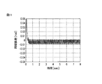
実施例2に係るサーボ制御装置による効果を実施例1の場合と同様に創成歯車加工機の場合を例にとって数値シミュレーションで確認した結果を図11に示す。実施例2に係るサーボ制御装置においては、速度制御帯域を150[Hz]まで上げても振動は発生せず、安定であった。 FIG. 11 shows the result of confirming the effect of the servo control device according to the second embodiment by numerical simulation, taking the case of a generating gear machining machine as in the case of the first embodiment. In the servo control device according to Example 2, no vibration was generated even when the speed control band was increased to 150 [Hz], and the servo control apparatus was stable.
以上のように、実施例2に係るサーボ制御装置によれば、速度フィードバックを微分して加速度を求め、これに定数を掛けてトルク指令を補正することで,振動を低減することができる。 As described above, according to the servo control device according to the second embodiment, the vibration can be reduced by differentiating the speed feedback to obtain the acceleration and multiplying the acceleration by a constant to correct the torque command.
以上の実施例の説明においては、創成歯車加工機を制御するサーボ制御装置を例にとって説明したが、これには限られず、本発明は、複数の軸を同期させて制御するサーボ制御装置であれば、立形マシニングセンタや旋盤等、他の工作機械にも適用可能である。 In the above description of the embodiment, the servo control device that controls the generating gear machining machine has been described as an example. However, the present invention is not limited to this, and the present invention may be a servo control device that controls a plurality of axes in synchronization. For example, it can be applied to other machine tools such as a vertical machining center and a lathe.
1 サーボ制御装置
2 第1軸速度フィードバック取得部
3 第2軸速度フィードバック取得部
4 速度変換部
5 速度差計算部
6 トルク補正計算部
7 第2軸トルク指令補正部
8 トルク補正値変換部
9 第1軸トルク指令補正部
DESCRIPTION OF
Claims (5)
第1の軸の速度フィードバック量を取得する第1軸速度フィードバック取得部と、
前記第1の軸と同期する第2の軸の速度フィードバック量を取得する第2軸速度フィードバック取得部と、
前記第1の軸の速度フィードバック量を前記第2の軸の速度フィードバック量と対応させるための変換係数を取得し、該変換係数を用いて前記第1の軸の速度フィードバック量を変換する速度変換部と、
変換された前記第1の軸の速度フィードバック量と、前記第2の軸の速度フィードバック量との速度差を計算する速度差計算部と、
前記速度差を用いて制振のためのトルク補正値を計算するトルク補正計算部と、
前記トルク補正値を用いて、第2の軸のトルク指令を補正する第2軸トルク指令補正部と、
第1の軸のトルク指令を補正するために、前記変換係数を用いて前記トルク補正値を変換するトルク補正値変換部と、
変換された前記トルク補正値を用いて、第1の軸のトルク指令を補正する第1軸トルク指令補正部と、
を備えることを特徴とするサーボ制御装置。 A servo control device that drives a first electric motor provided on a first shaft and a second electric motor provided on a second shaft in synchronization with each other,
A first axis speed feedback acquisition unit for acquiring a speed feedback amount of the first axis;
A second axis speed feedback acquisition unit for acquiring a speed feedback amount of a second axis synchronized with the first axis;
Speed conversion for acquiring a conversion coefficient for associating the speed feedback amount of the first axis with the speed feedback amount of the second axis, and converting the speed feedback amount of the first axis using the conversion coefficient And
A speed difference calculator for calculating a speed difference between the converted speed feedback amount of the first axis and the speed feedback amount of the second axis;
A torque correction calculation unit for calculating a torque correction value for vibration suppression using the speed difference;
A second axis torque command correction unit for correcting a torque command of the second axis using the torque correction value;
A torque correction value converter that converts the torque correction value using the conversion coefficient in order to correct the torque command of the first axis;
A first axis torque command correction unit that corrects a torque command of the first axis using the converted torque correction value;
A servo control device comprising:
ねじれ剛性を補正するために、前記速度差を積算した値に第1定数を乗算する積分計算部と、
摩擦を補正するために、前記速度差に第2定数を乗算する比例計算部と、
前記積分計算部の計算結果と、前記比例計算部の計算結果とを加算する加算部と、
加算された前記計算結果の位相調整を行う位相進めフィルタと、
を含む、請求項1に記載のサーボ制御装置。 The torque correction calculator is
An integral calculator that multiplies a value obtained by integrating the speed differences by a first constant to correct torsional stiffness;
A proportional calculator for multiplying the speed difference by a second constant to correct friction;
An addition unit for adding the calculation result of the integral calculation unit and the calculation result of the proportional calculation unit;
A phase advance filter for adjusting the phase of the added calculation result;
The servo control device according to claim 1, comprising:
第1の軸の速度フィードバック量を取得する第1軸速度フィードバック取得部と、
前記第1の軸の速度フィードバック量を第2の軸の速度フィードバック量と対応させるための変換係数を取得し、該変換係数を用いて前記第1の軸の速度フィードバック量を変換する速度変換部と、
変換された前記第1の軸の速度フィードバック量を微分し、所定の定数を乗算する第2軸微分計算部と、
位相調整を行う第2軸位相進みフィルタと、
得られた第2軸用トルク補正値に基づいて、第2の軸のトルク指令を補正する第2軸トルク指令補正部と、
前記第1の軸と同期する第2の軸の速度フィードバック量を取得する第2軸速度フィードバック取得部と、
前記第2の軸の速度フィードバック量を微分し、所定の定数を乗算する第1軸微分計算部と、
位相調整を行う第1軸位相進みフィルタと、
変換係数を用いて、得られた第1軸用トルク補正値を変換するトルク補正値変換部と、
変換された前記第1軸用トルク補正値を用いて、第1の軸のトルク指令を補正する第1軸トルク指令補正部と、
を備えることを特徴とするサーボ制御装置。 A servo control device that drives a first electric motor provided on a first shaft and a second electric motor provided on a second shaft in synchronization with each other,
A first axis speed feedback acquisition unit for acquiring a speed feedback amount of the first axis;
A speed conversion unit that acquires a conversion coefficient for causing the speed feedback amount of the first axis to correspond to the speed feedback amount of the second axis, and converts the speed feedback amount of the first axis using the conversion coefficient When,
A second axis differential calculation unit for differentiating the converted speed feedback amount of the first axis and multiplying by a predetermined constant;
A second axis phase advance filter for phase adjustment;
A second shaft torque command correction unit for correcting a torque command for the second shaft based on the obtained second shaft torque correction value;
A second axis speed feedback acquisition unit for acquiring a speed feedback amount of a second axis synchronized with the first axis;
A first axis differential calculation unit for differentiating the speed feedback amount of the second axis and multiplying by a predetermined constant;
A first axis phase advance filter for phase adjustment;
A torque correction value converter that converts the obtained torque correction value for the first axis using the conversion coefficient;
A first axis torque command correction unit that corrects a torque command of the first axis using the converted torque correction value for the first axis;
A servo control device comprising:
前記第1軸トルク指令補正部及び前記第2軸トルク指令補正部は、前記加工状態信号に応じて、第1の軸のトルク指令または第2の軸のトルク指令を補正する、請求項1乃至4のいずれか一項に記載のサーボ制御装置。 A coupling state detection unit that receives a machining state signal indicating whether the tool and the workpiece are in contact with each other;
The first shaft torque command correction unit and the second shaft torque command correction unit correct a torque command of the first shaft or a torque command of the second shaft according to the machining state signal. 5. The servo control device according to any one of 4.
Priority Applications (4)
| Application Number | Priority Date | Filing Date | Title |
|---|---|---|---|
| JP2014058642A JP5863860B2 (en) | 2014-03-20 | 2014-03-20 | Servo controller that reduces interference between axes during machining |
| DE102015003243.7A DE102015003243B4 (en) | 2014-03-20 | 2015-03-13 | Servo control device for reducing interference between axes during machining |
| US14/662,409 US9304504B2 (en) | 2014-03-20 | 2015-03-19 | Servo controller for reducing interference between axes in machining |
| CN201510125799.1A CN104965482B (en) | 2014-03-20 | 2015-03-20 | The Servocontrol device of the interference of between centers during reduction processing |
Applications Claiming Priority (1)
| Application Number | Priority Date | Filing Date | Title |
|---|---|---|---|
| JP2014058642A JP5863860B2 (en) | 2014-03-20 | 2014-03-20 | Servo controller that reduces interference between axes during machining |
Publications (2)
| Publication Number | Publication Date |
|---|---|
| JP2015186295A JP2015186295A (en) | 2015-10-22 |
| JP5863860B2 true JP5863860B2 (en) | 2016-02-17 |
Family
ID=54053706
Family Applications (1)
| Application Number | Title | Priority Date | Filing Date |
|---|---|---|---|
| JP2014058642A Active JP5863860B2 (en) | 2014-03-20 | 2014-03-20 | Servo controller that reduces interference between axes during machining |
Country Status (4)
| Country | Link |
|---|---|
| US (1) | US9304504B2 (en) |
| JP (1) | JP5863860B2 (en) |
| CN (1) | CN104965482B (en) |
| DE (1) | DE102015003243B4 (en) |
Cited By (2)
| Publication number | Priority date | Publication date | Assignee | Title |
|---|---|---|---|---|
| US11003168B2 (en) | 2018-10-02 | 2021-05-11 | Fanuc Corporation | Controller for gear cutting machine |
| US11022958B2 (en) | 2018-10-02 | 2021-06-01 | Fanuc Corporation | Disturbance component identification method and disturbance component identification device |
Families Citing this family (10)
| Publication number | Priority date | Publication date | Assignee | Title |
|---|---|---|---|---|
| JP6154435B2 (en) * | 2015-07-09 | 2017-06-28 | ファナック株式会社 | Servo control device with function to display online automatic adjustment status of control system |
| ES2936406T3 (en) * | 2016-05-10 | 2023-03-16 | Panasonic Ip Man Co Ltd | engine control system |
| DE112016007254B4 (en) * | 2016-09-23 | 2020-12-10 | Yamaha Hatsudoki Kabushiki Kaisha | Robot system, robot control or regulation, robot control or regulation method and robot program |
| WO2018179368A1 (en) * | 2017-03-31 | 2018-10-04 | 三菱電機株式会社 | Control device and motor control system |
| JP6474460B2 (en) * | 2017-06-21 | 2019-02-27 | ファナック株式会社 | Motor control device |
| JP6683748B2 (en) * | 2018-02-23 | 2020-04-22 | ファナック株式会社 | Numerical control device |
| KR102589984B1 (en) * | 2018-08-31 | 2023-10-16 | 주식회사 디엔솔루션즈 | Resonance suppression control device of machine tool and method thereof |
| EP3683471B1 (en) * | 2019-01-15 | 2024-03-06 | ABB Schweiz AG | Damping torsional oscillations in a drive system |
| CN111152213B (en) * | 2019-12-05 | 2021-03-16 | 北京蒂斯科技有限公司 | Mechanical arm vibration compensation method and device based on hybrid control |
| CN113285632A (en) * | 2020-02-19 | 2021-08-20 | 广西汽车集团有限公司 | Dual-motor synchronous control method and device |
Family Cites Families (10)
| Publication number | Priority date | Publication date | Assignee | Title |
|---|---|---|---|---|
| KR930001093B1 (en) | 1987-03-31 | 1993-02-15 | 부라더 고교 가부시키가이샤 | Thread cutting machine with synchronized feed and rotation motors |
| JP2629729B2 (en) * | 1987-08-28 | 1997-07-16 | ブラザー工業株式会社 | Screw processing equipment |
| JPH09192929A (en) * | 1996-01-17 | 1997-07-29 | Toyota Motor Corp | Device for controlling machine tool and method thereof |
| DE19882519B4 (en) * | 1997-07-02 | 2005-12-22 | Mitsubishi Denki K.K. | Synchronization control unit for a servomotor |
| JP3492583B2 (en) * | 2000-03-27 | 2004-02-03 | ファナック株式会社 | Servo control device |
| JP4391218B2 (en) * | 2003-02-20 | 2009-12-24 | 三菱電機株式会社 | Servo control device |
| JP4658181B2 (en) | 2003-02-20 | 2011-03-23 | 三菱電機株式会社 | Servo control device |
| JP4506178B2 (en) * | 2003-08-25 | 2010-07-21 | 株式会社安川電機 | Gear synchronous machining apparatus and control method thereof |
| JP4673326B2 (en) * | 2007-01-11 | 2011-04-20 | オークマ株式会社 | Rotary shaft position control device |
| JP6209320B2 (en) | 2012-09-19 | 2017-10-04 | 住友ゴム工業株式会社 | Rubber composition for tread and pneumatic tire |
-
2014
- 2014-03-20 JP JP2014058642A patent/JP5863860B2/en active Active
-
2015
- 2015-03-13 DE DE102015003243.7A patent/DE102015003243B4/en active Active
- 2015-03-19 US US14/662,409 patent/US9304504B2/en active Active
- 2015-03-20 CN CN201510125799.1A patent/CN104965482B/en active Active
Cited By (2)
| Publication number | Priority date | Publication date | Assignee | Title |
|---|---|---|---|---|
| US11003168B2 (en) | 2018-10-02 | 2021-05-11 | Fanuc Corporation | Controller for gear cutting machine |
| US11022958B2 (en) | 2018-10-02 | 2021-06-01 | Fanuc Corporation | Disturbance component identification method and disturbance component identification device |
Also Published As
| Publication number | Publication date |
|---|---|
| US20150268658A1 (en) | 2015-09-24 |
| US9304504B2 (en) | 2016-04-05 |
| DE102015003243A1 (en) | 2015-09-24 |
| JP2015186295A (en) | 2015-10-22 |
| CN104965482B (en) | 2017-06-09 |
| CN104965482A (en) | 2015-10-07 |
| DE102015003243B4 (en) | 2017-09-21 |
Similar Documents
| Publication | Publication Date | Title |
|---|---|---|
| JP5863860B2 (en) | Servo controller that reduces interference between axes during machining | |
| CN107533325B (en) | Mechanical motion track measuring device | |
| JP5192571B2 (en) | Control device for driving one driven body with two electric motors | |
| JP6316323B2 (en) | Motor control device | |
| JP3923047B2 (en) | Synchronous control device | |
| EP3118710B1 (en) | Feed shaft control method and numerical control work device | |
| US9523975B2 (en) | Servo controller for reducing synchronous error in synchronous machining | |
| CN105710711A (en) | Position Controller Of Feed Axis In Machine Tool | |
| JP4944806B2 (en) | Position control device | |
| JP2008210273A (en) | Method of compensating friction, friction compensator, and motor control device | |
| TWI705657B (en) | Motor control device | |
| JP4867105B2 (en) | Numerical controller | |
| TWI508425B (en) | Motor controlling method and motor controlling apparatus | |
| JP4612032B2 (en) | Machine tool controller | |
| WO2007029825A1 (en) | Position control device | |
| JP7049754B2 (en) | Motor control device | |
| JP5369718B2 (en) | Machine Tools | |
| JP2014002461A (en) | Numerical control device | |
| JP6391489B2 (en) | Motor control device | |
| JP2004310261A (en) | Motor-controlling device | |
| JP2018092357A (en) | Servo motor control apparatus, servomotor control method, and computer program | |
| JPH0380311A (en) | Disturbance torque compensator |
Legal Events
| Date | Code | Title | Description |
|---|---|---|---|
| A131 | Notification of reasons for refusal |
Free format text: JAPANESE INTERMEDIATE CODE: A131 Effective date: 20150811 |
|
| TRDD | Decision of grant or rejection written | ||
| A01 | Written decision to grant a patent or to grant a registration (utility model) |
Free format text: JAPANESE INTERMEDIATE CODE: A01 Effective date: 20151208 |
|
| A61 | First payment of annual fees (during grant procedure) |
Free format text: JAPANESE INTERMEDIATE CODE: A61 Effective date: 20151222 |
|
| R150 | Certificate of patent or registration of utility model |
Ref document number: 5863860 Country of ref document: JP Free format text: JAPANESE INTERMEDIATE CODE: R150 |