JP5863576B2 - Method, apparatus and system for digital radiation curable gel ink printing with UV gel ink planarization and jet deposition directly on a substrate having a planarizing member with a metal oxide surface - Google Patents
Method, apparatus and system for digital radiation curable gel ink printing with UV gel ink planarization and jet deposition directly on a substrate having a planarizing member with a metal oxide surface Download PDFInfo
- Publication number
- JP5863576B2 JP5863576B2 JP2012141875A JP2012141875A JP5863576B2 JP 5863576 B2 JP5863576 B2 JP 5863576B2 JP 2012141875 A JP2012141875 A JP 2012141875A JP 2012141875 A JP2012141875 A JP 2012141875A JP 5863576 B2 JP5863576 B2 JP 5863576B2
- Authority
- JP
- Japan
- Prior art keywords
- ink
- gel ink
- contact member
- substrate
- contact
- Prior art date
- Legal status (The legal status is an assumption and is not a legal conclusion. Google has not performed a legal analysis and makes no representation as to the accuracy of the status listed.)
- Expired - Fee Related
Links
- 239000000758 substrate Substances 0.000 title claims description 67
- 230000005855 radiation Effects 0.000 title claims description 54
- 238000000034 method Methods 0.000 title claims description 45
- 150000004706 metal oxides Chemical class 0.000 title claims description 44
- 229910044991 metal oxide Inorganic materials 0.000 title claims description 41
- 238000001540 jet deposition Methods 0.000 title description 2
- 239000012530 fluid Substances 0.000 claims description 38
- GWEVSGVZZGPLCZ-UHFFFAOYSA-N Titan oxide Chemical compound O=[Ti]=O GWEVSGVZZGPLCZ-UHFFFAOYSA-N 0.000 claims description 26
- 230000008569 process Effects 0.000 claims description 22
- 239000004408 titanium dioxide Substances 0.000 claims description 11
- WGLPBDUCMAPZCE-UHFFFAOYSA-N Trioxochromium Chemical compound O=[Cr](=O)=O WGLPBDUCMAPZCE-UHFFFAOYSA-N 0.000 claims description 9
- 229910000423 chromium oxide Inorganic materials 0.000 claims description 9
- 229920000642 polymer Polymers 0.000 claims description 4
- 239000004094 surface-active agent Substances 0.000 claims description 4
- 239000007921 spray Substances 0.000 claims description 3
- 150000001875 compounds Chemical class 0.000 claims description 2
- 238000003825 pressing Methods 0.000 claims 1
- 239000000976 ink Substances 0.000 description 199
- 239000000463 material Substances 0.000 description 8
- 239000002245 particle Substances 0.000 description 8
- 238000005498 polishing Methods 0.000 description 8
- XLYOFNOQVPJJNP-UHFFFAOYSA-N water Substances O XLYOFNOQVPJJNP-UHFFFAOYSA-N 0.000 description 7
- 238000000576 coating method Methods 0.000 description 4
- 238000000151 deposition Methods 0.000 description 4
- 238000010586 diagram Methods 0.000 description 4
- 238000010894 electron beam technology Methods 0.000 description 4
- 238000007750 plasma spraying Methods 0.000 description 4
- DBMJMQXJHONAFJ-UHFFFAOYSA-M Sodium laurylsulphate Chemical compound [Na+].CCCCCCCCCCCCOS([O-])(=O)=O DBMJMQXJHONAFJ-UHFFFAOYSA-M 0.000 description 3
- 230000015572 biosynthetic process Effects 0.000 description 3
- 230000003993 interaction Effects 0.000 description 3
- 239000007788 liquid Substances 0.000 description 3
- 239000011159 matrix material Substances 0.000 description 3
- 239000011224 oxide ceramic Substances 0.000 description 3
- 229910001111 Fine metal Inorganic materials 0.000 description 2
- 239000002518 antifoaming agent Substances 0.000 description 2
- 239000000919 ceramic Substances 0.000 description 2
- 230000008859 change Effects 0.000 description 2
- 239000003795 chemical substances by application Substances 0.000 description 2
- 230000001678 irradiating effect Effects 0.000 description 2
- 239000000203 mixture Substances 0.000 description 2
- 239000000178 monomer Substances 0.000 description 2
- 229920001296 polysiloxane Polymers 0.000 description 2
- 239000004809 Teflon Substances 0.000 description 1
- 229920006362 Teflon® Polymers 0.000 description 1
- 238000010521 absorption reaction Methods 0.000 description 1
- 230000009471 action Effects 0.000 description 1
- 230000008901 benefit Effects 0.000 description 1
- -1 chromium oxide Chemical class 0.000 description 1
- 239000011248 coating agent Substances 0.000 description 1
- 230000008021 deposition Effects 0.000 description 1
- 230000002542 deteriorative effect Effects 0.000 description 1
- 230000005660 hydrophilic surface Effects 0.000 description 1
- 239000011148 porous material Substances 0.000 description 1
- 238000009718 spray deposition Methods 0.000 description 1
- 238000005507 spraying Methods 0.000 description 1
- 239000000126 substance Substances 0.000 description 1
- 238000007740 vapor deposition Methods 0.000 description 1
Images


Classifications
-
- B—PERFORMING OPERATIONS; TRANSPORTING
- B41—PRINTING; LINING MACHINES; TYPEWRITERS; STAMPS
- B41M—PRINTING, DUPLICATING, MARKING, OR COPYING PROCESSES; COLOUR PRINTING
- B41M7/00—After-treatment of prints, e.g. heating, irradiating, setting of the ink, protection of the printed stock
-
- B—PERFORMING OPERATIONS; TRANSPORTING
- B41—PRINTING; LINING MACHINES; TYPEWRITERS; STAMPS
- B41M—PRINTING, DUPLICATING, MARKING, OR COPYING PROCESSES; COLOUR PRINTING
- B41M7/00—After-treatment of prints, e.g. heating, irradiating, setting of the ink, protection of the printed stock
- B41M7/0072—After-treatment of prints, e.g. heating, irradiating, setting of the ink, protection of the printed stock using mechanical wave energy, e.g. ultrasonics; using magnetic or electric fields, e.g. electric discharge, plasma
Description
本開示は、放射線硬化性ゲルインク平坦化のための方法、装置、およびシステムに関する。特に、開示は、平坦化ロールの金属酸化物被覆表面を用いてゲルインクを接触平坦化するための方法、装置、およびシステムに関する。 The present disclosure relates to methods, apparatus, and systems for radiation curable gel ink planarization. In particular, the disclosure relates to a method, apparatus, and system for contact planarizing gel inks using a metal oxide coated surface of a planarizing roll.
放射線硬化性ゲルインク、例えば、UV硬化性ゲルインクなどは、被印刷物上に直接に噴射したとき、従来のインクにより形成される滴よりも低い流動性を有する滴を形成する傾向がある。画像を形成するために基材上に直接に蒸着する予定のUVゲルインクを印字ヘッドから噴射するとき、インク滴は液体である。滴が基材に接触すると、滴はゲル状態まで急冷され、その結果、滴は限られた流動性を有する。 Radiation curable gel inks, such as UV curable gel inks, tend to form drops that have lower fluidity than those formed by conventional inks when jetted directly onto a substrate. When the UV gel ink that is to be deposited directly on the substrate to form an image is ejected from the print head, the ink drops are liquid. When the drop contacts the substrate, the drop is quenched to a gel state, so that the drop has limited fluidity.
従来のインクは、基材と接触した途端に流動性の液滴を形成する傾向がある。印刷中に流動性液体インク滴同士が合体するのを防止するために、通常、基材を被覆したり、および/または処理したりする。また、例えば、付着特性を高めて表面エネルギーを増大させたり、または他の方法で紙基材とインクの間の化学的相互作用に影響を与えたりする材料を用いて、従来のインクとともに使用する紙基材を被覆してもよい。このような被覆または処理は媒体に適用する特別な工程を必要とし、印刷工程においてそれらの被覆または処理を使用するには追加費用をともなう。例えば、デジタルプレス機と従来のプレス機とを用いる印刷プロセスが、各プレス機に適した異なる媒体供給を必要とする可能性がある。 Conventional inks tend to form fluid droplets as soon as they come into contact with the substrate. In order to prevent fluid liquid ink droplets from coalescing during printing, the substrate is usually coated and / or treated. Also used with conventional inks, for example, with materials that enhance adhesion properties to increase surface energy, or otherwise affect the chemical interaction between the paper substrate and the ink A paper substrate may be coated. Such coatings or processes require special steps applied to the media, and there is an additional cost to use those coatings or processes in the printing process. For example, a printing process using a digital press and a conventional press may require a different media supply suitable for each press.
放射線硬化性ゲルインクは、基材がどのように処理されているかにかかわらず、さまざまな基材タイプ上で優れた滴の位置決めを少なくとも示すため、印刷工程にとって有利である。例えば、複数の印刷装置にわたって同じ媒体または同じ基材タイプを印刷することと、例えば、特殊な被覆を施したストックなどを運ぶ必要がないこととが、コスト的に有利である。 Radiation curable gel inks are advantageous for the printing process because they exhibit at least excellent drop positioning on a variety of substrate types, regardless of how the substrate is being processed. For example, printing the same media or the same substrate type across multiple printing devices and not having to carry stocks with special coatings, etc. are cost effective.
放射線硬化性ゲルインク画像は、一貫性のないインク滴線幅および/または好ましくないパイル高さに起因する凹凸により丸太を並べたように見える印刷アーチファクトに苦しむ可能性がある。噴射されたゲルインクラインの一様性を実現するために、および/またはさまざまな線幅に対処して好ましくない印刷アーチファクトを取り除くために、フラッドコートに依存することは費用がかかるとともに、いくつかの印刷ジョブにとって好ましくない可能性がある高い光沢度をもたらす可能性がある。他の方法で、例えば、接触部材上にゲルインクを裏移りさせることで、印刷した画像を悪化させることなしに、基材上にインクを直接に噴射した後にゲルインクを平坦化することにより、好ましくないパイル高さおよび/または一貫性のないインク線幅に対して、費用効率が高くかつ効果的な方法で対処する装置およびシステムからゲル・インク・プロセスが恩恵を受けてもよい。 Radiation curable gel ink images can suffer from print artifacts that appear to be aligned with logs due to irregularities due to inconsistent ink drop line widths and / or undesirable pile heights. Relying on a floodcoat to achieve uniformity of the ejected gel ink line and / or to deal with various line widths and eliminate undesirable printing artifacts is expensive and has several This can lead to high gloss levels that can be undesirable for a print job. In other ways, for example, by transferring the gel ink onto the contact member, it is not preferable to flatten the gel ink after jetting the ink directly onto the substrate without deteriorating the printed image. The gel ink process may benefit from devices and systems that address pile height and / or inconsistent ink line width in a cost-effective and effective manner.
実施形態によるシステムは、紫外線(「UV」)ゲルインクのような放射線硬化性ゲルインクを巻き取り紙のような基材上に直接に噴射するための印字ヘッドを有する放射線硬化性ゲルインク印刷システムを含んでいてもよい。他の実施形態では、他の任意の放射線硬化インク蒸着方法および/またはシステムのうちの1つ以上を用いて基材上にゲルインクを蒸着してもよい。 A system according to embodiments includes a radiation curable gel ink printing system having a print head for jetting radiation curable gel ink, such as ultraviolet ("UV") gel ink, directly onto a substrate, such as a web. May be. In other embodiments, the gel ink may be deposited on the substrate using one or more of any other radiation curable ink deposition methods and / or systems.
実施形態のシステムは、接触部材へのインクの裏移りが最小の状態またはまったくない状態で、基材上に噴射されたUVゲルインクと接触するようになされた接触部材を有する、および/または基材上に噴射されたUVゲルインクに圧力をかける、UV硬化性インク平坦化装置を含んでいてもよい。接触部材は、基材上のインクと接触する流体層と接触する親水性の外部接触表面を含んでいる。接触部材は対向する部材と連動して、その中を通って基材がプロセス方向に移動してもよい平坦化ニップを形成してもよい。 The system of embodiments has a contact member adapted to contact the UV gel ink jetted onto the substrate with minimal or no ink set-off to the contact member and / or the substrate A UV curable ink flattening device may be included that applies pressure to the UV gel ink sprayed thereon. The contact member includes a hydrophilic external contact surface that contacts a fluid layer that contacts the ink on the substrate. The contact member may interlock with the opposing member to form a planarization nip through which the substrate may move in the process direction.
一実施形態による装置およびシステムは、UV硬化性ゲルインクにUV放射を作用させるための1つ以上のUV光源を含んでいてもよい。UV光源は、ゲルインクを所望程度まで硬化させたり、または所望量のゲルインクを重合させたりするようになされていてもよい。例えば、露光されたインクのうちの少ない割合を重合させるようにゲルインクを硬化させてもよい。あるいは、露光されたインクのうちのかなり大きな部分を重合させるようにゲルインクを硬化させてもよい。特に、基材上に位置付けられたゲルインクに放射を作用させるようにUV光源を構成して、ゲルインクが固まるように、したがって、接触部材へのインクの裏移りが最小の状態またはまったくない状態で、接触部材がインクと接触できるようにしてもよい。インクが接触部材により平坦化された後にインクを硬化するようにUV光源を構成してもよい。システムは、平坦化ニップにおいてゲルインクを平坦化する前にゲルインク画像を照射するための第1のUV光源と、ゲルインクを平坦化した後にゲルインクを照射して、ゲルインク画像を硬化するための第2のUV光源と、を含んでいてもよい。放射線硬化性インクを蒸着して、平坦化して、電子ビーム装置のようなUV以外の硬化装置を用いて硬化するようにシステムを構成してもよい。 An apparatus and system according to one embodiment may include one or more UV light sources for applying UV radiation to the UV curable gel ink. The UV light source may be configured to cure the gel ink to a desired degree or to polymerize a desired amount of gel ink. For example, the gel ink may be cured so that a small proportion of the exposed ink is polymerized. Alternatively, the gel ink may be cured to polymerize a significant portion of the exposed ink. In particular, the UV light source is configured to cause radiation to act on the gel ink positioned on the substrate so that the gel ink hardens, and thus with minimal or no ink set-off to the contact member, The contact member may be in contact with ink. The UV light source may be configured to cure the ink after it has been planarized by the contact member. The system includes a first UV light source for irradiating the gel ink image before flattening the gel ink in the flattening nip, and a second UV light source for irradiating the gel ink after flattening the gel ink to cure the gel ink image. And a UV light source. The system may be configured to deposit and planarize radiation curable ink and to cure using a curing device other than UV, such as an electron beam device.
装置およびシステムは、親水性で、耐久性があり、比較的安価で入手しやすい接触表面を有する接触部材を含んでいてもよい。特に、装置およびシステムは金属酸化物を含む接触表面を含んでいる。接触部材の表面上に金属酸化物をプラズマ溶射してもよい。一実施形態では、接触表面は、きめ細かい多孔質母材を生成するために研摩され、つや出しされたプラズマ溶射した金属酸化物被覆を含んでいてもよい。接触部材の接触表面は、二酸化チタンまたはチタニアを含んでいてもよい。他の実施形態では、接触部材の接触表面は酸化クロムを含んでいてもよい。 The apparatus and system may include a contact member having a contact surface that is hydrophilic, durable, relatively inexpensive and readily available. In particular, the apparatus and system include a contact surface that includes a metal oxide. A metal oxide may be plasma sprayed onto the surface of the contact member. In one embodiment, the contact surface may include a plasma sprayed metal oxide coating that has been polished and polished to produce a fine porous matrix. The contact surface of the contact member may include titanium dioxide or titania. In other embodiments, the contact surface of the contact member may include chromium oxide.
装置およびシステムは、犠牲剥離層流体を含むための、および/または接触部材の表面に犠牲剥離層流体を付加するための犠牲剥離層流体システムを含んでいてもよい。例えば、蒸着したUVゲルインク画像に接触部材が接触してゲルインク画像のインクを平坦化する前に、印刷プロセス内の接触部材の表面に剥離流体を付加してもよい。 The apparatus and system may include a sacrificial release layer fluid system for containing the sacrificial release layer fluid and / or for applying the sacrificial release layer fluid to the surface of the contact member. For example, a release fluid may be applied to the surface of the contact member in the printing process before the contact member contacts the deposited UV gel ink image to flatten the ink of the gel ink image.
一実施形態の方法は、巻き取り紙などの基材上に直接に蒸着するUVゲルインクのような放射線硬化性ゲルインクを、金属酸化物表面を有する接触部材と接触させることを含んでいてもよい。接触部材は親水性セラミック表面を有する回転ロールであってもよく、接触部材は対向する部材と連動して、その中を通って基材をプロセス方向に移動させてもよい平坦化ニップを形成してもよい。一実施形態では、接触部材は二酸化チタンを含む接触表面を有していてもよい。他の実施形態では、接触表面は酸化クロムを含んでいてもよい。 The method of one embodiment may include contacting a radiation curable gel ink, such as a UV gel ink, that is deposited directly on a substrate such as a web with a contact member having a metal oxide surface. The contact member may be a rotating roll having a hydrophilic ceramic surface, and the contact member interlocks with the opposing member to form a planarizing nip through which the substrate may be moved in the process direction. May be. In one embodiment, the contact member may have a contact surface comprising titanium dioxide. In other embodiments, the contact surface may include chromium oxide.
一実施形態による方法は、インクジェット印字ヘッドにより基材の表面上に直接に噴射されたUVゲルインクにUV放射を作用させることを含んでいてもよい。特に、UV光源は、それによりゲルインクを硬化させてインクの粘度を変えるようになされていてもよい。例えば、インク画像を部分的にのみ重合させてもよく、または最終的な硬化のためにインク画像のインクのうちのかなり大きな割合を重合させてもよい。平坦化するためにインクを接触部材と接触させる前に、インクを固めるために、噴射されたUVゲルインクにUV放射を作用させて、それにより、平坦化プロセス中にインクが接触部材に裏移りするのを最小限に抑えることが好ましい可能性がある。他の実施形態では、放射線硬化性ゲルインクを使用してもよく、所定量のインクを重合させるのに効果的な放射線を作用させるように構成された、例えば、電子ビーム装置などを含む任意のシステムを使用してもよい。 A method according to one embodiment may include applying UV radiation to UV gel ink jetted directly onto the surface of the substrate by an inkjet printhead. In particular, the UV light source may be adapted to cure the gel ink thereby changing the viscosity of the ink. For example, the ink image may be polymerized only partially, or a significant percentage of the ink of the ink image may be polymerized for final curing. Prior to bringing the ink into contact with the contact member for flattening, UV radiation is applied to the jetted UV gel ink to harden the ink, thereby causing the ink to set off to the contact member during the flattening process. It may be preferable to minimize this. In other embodiments, radiation curable gel inks may be used, and any system configured to apply radiation effective to polymerize a predetermined amount of ink, including, for example, an electron beam device May be used.
他の実施形態では、方法は、基材上に直接に蒸着した放射線硬化性ゲルインク、例えば、UVゲルインクなどに、接触部材の金属酸化物表面を当てる前に、平坦化装置の接触部材の接触表面に水性の犠牲剥離流体を付加することを含んでいる。接触部材は、きめ細かい多孔質母材を形成する、プラズマ溶射した金属酸化物セラミック表面を含んでいてもよい。例えば、接触部材は約25ミクロンの厚さを有する金属酸化物セラミック表面を含んでいてもよい。プラズマ溶射した金属酸化物の粒径が、約5ミクロン以下であってもよい。犠牲剥離層は、水と、界面活性剤および/または好適な高分子化合物と、を含んでいてもよい。 In other embodiments, the method includes contacting the contact surface of the planarizing device contact member before applying the metal oxide surface of the contact member to a radiation curable gel ink, such as UV gel ink, deposited directly on the substrate. Adding an aqueous sacrificial stripping fluid. The contact member may include a plasma sprayed metal oxide ceramic surface that forms a fine porous matrix. For example, the contact member may include a metal oxide ceramic surface having a thickness of about 25 microns. The particle size of the plasma sprayed metal oxide may be about 5 microns or less. The sacrificial release layer may contain water and a surfactant and / or a suitable polymer compound.
他の実施形態によるシステムは、水の保持と、剥離流体膜の形成と、水性の剥離流体の提供とを促進する金属酸化物を含む表面を含む接触部材を有する基材上に直接に噴射蒸着する方式のUVゲル・インク・デジタル印刷システム用のUVゲルインク平坦化装置を含んでいる。接触部材の表面上に金属酸化物をプラズマ溶射して、溶射した金属酸化物粒子を研摩して、接触表面上の金属酸化物をつや出しすることにより、接触部材の接触表面を形成して、きめ細かい多孔質金属酸化物母材を形成してもよい。接触部材の表面に水性の犠牲剥離流体を付加するように流体剥離システムを構成してもよい。 A system according to another embodiment directly jet deposits onto a substrate having a contact member that includes a surface comprising a metal oxide that promotes water retention, release fluid film formation, and provision of an aqueous release fluid. A UV gel ink flattening device for a UV gel ink digital printing system of the type Plasma spraying metal oxide on the surface of the contact member, polishing the sprayed metal oxide particles, and polishing the metal oxide on the contact surface to form the contact surface of the contact member and fine A porous metal oxide base material may be formed. The fluid stripping system may be configured to add an aqueous sacrificial stripping fluid to the surface of the contact member.
図1は、例示的実施形態の放射線硬化性ゲルインク印刷システムと、平坦化装置とを示している。詳細には、図1は、UVゲルインクを噴射するための印字ヘッド105を有するUVゲルインク印刷システムを示している。UVゲルインク印刷システムは、接触部材107を有する平坦化装置を含んでいてもよい。例えば、UVゲルインクを基材上に直接に噴射したり、または蒸着したりして、噴射したままの状態の画像110を形成するように印字ヘッド105を構成してもよい。例えば、印字ヘッド105はウェブ112のような基材上にインクを噴射してもよい。ウェブは、例えば、巻き取り紙であってもよい。他の実施形態では、基材はカットシートであってもよい。ブラック、クリア、マゼンタ、シアン、イエロー、または他の任意の所望のインク色であってもよい1つ以上のインクを含み、および/またはその1つ以上のインクを蒸着したり、または噴射したりするように印字ヘッド105を構成してもよい。
FIG. 1 illustrates an exemplary embodiment of a radiation curable gel ink printing system and a planarizing device. Specifically, FIG. 1 shows a UV gel ink printing system having a
ゲルインクは任意の放射線硬化性インクであってもよい。例えば、ゲルインクはUV放射硬化性であってもよい。さらに、インクジェット印字ヘッド以外の手段によりゲルインクを蒸着してもよい。任意の好適なインク蒸着手段により基材上に直接にインクを蒸着してもよい。例えば、図1に示すようにインクジェット印字ヘッド105によりインクを噴射してもよく、または液体状態まで加熱されたゲルインクを含み基材上にゲルインクを蒸着するように構成された微小電気機械システムのようなシステムによりインクを蒸着してもよい。
The gel ink may be any radiation curable ink. For example, the gel ink may be UV radiation curable. Further, the gel ink may be deposited by means other than the ink jet print head. The ink may be deposited directly on the substrate by any suitable ink deposition means. For example, as shown in FIG. 1, an ink may be ejected by an
ウェブ112上にUVゲルインクを噴射した後に、ウェブを平坦化装置の接触部材107までプロセス方向に移動させてもよい。図1に示すように、接触部材107は中心縦軸のまわりに回転可能なドラムまたはロールであってもよい。接触部材は、基材112のインク保持表面上の、例えば、噴射されたインク画像110などの噴射されたインクと接触するように構成してもよい接触表面を含んでいてもよい。
After jetting the UV gel ink onto the
一実施形態では、接触部材107は圧力ロールなどの対向する部材と連動してもよく、接触部材107はロール・オン・ロール平坦化のためにそれらの間に平坦化ニップを形成するように構成されてもよい。インク画像110のゲルインクを平坦化するために、ウェブ112は、ニップを通って噴射されたインク画像110を運ぶように構成されてもよい。接触部材107は、基材上のインクに圧力をかけて、平坦化されたインク画像120を生成することにより、噴射されたインク画像110のインクを平坦化する。
In one embodiment, the
一実施形態では、接触部材107はUV光源と連動してもよい。図1に示すように、UVゲルインク印刷システムは、UV光源145を含んでいてもよい。UV光源145は、接触部材107がインクを平坦化する前に、噴射されたインク画像110のインクにUV放射を作用させるようになされていてもよい。
In one embodiment, the
インクを硬化するようにUV光源145を構成して、所定量のインクを重合させるようになっていてもよい。例えば、インク画像110を含む少量のインクを重合させてもよい。あるいは、かなり多量のインクを重合させてもよい。例えば、UV光源は、ゲルインク画像のUV硬化性ゲルインクを照射して最終的な硬化を行うようになされていてもよい。
The UV
インク画像110のゲルインクにUV放射を作用させるようにUV光源145を構成して、接触部材107がインクと接触する前に十分な量のゲルインクを重合させてインクの粘度を変えることが好ましい可能性がある。例えば、平坦化ニップにおける接触部材107によるインクの平坦化および/または接触時にUV硬化性ゲルインクが接触部材107に裏移りするのを最小限に抑えたり、またはなくしたりするためにインクの粘度を変えてもよい。裏移りを最小限に抑えたり、または防止したりするのに必要な硬化量は、例えば、ゲル量、モノマー組成、および存在する光開始剤量などを含むインク特性に依存してもよい。さらに、適用する硬化量は、放射波長、および光開始剤との相互作用と、波長、強度、および時間の組み合わせを含む露出量と、に依存してもよい。
It may be preferable to configure the
一実施形態では、UV光源145は第1のUV光源であってもよく、UV硬化性ゲル・インク・デジタル印刷システムは第2のUV光源150を含んでいてもよい。平坦化されたインク画像120を生成するために接触部材107が画像110のインクを平坦化した後に、噴射されたインク画像110のインクにUV放射を作用させるように第2のUV光源150を構成してもよい。図1に示すように、平坦化されたインク画像120を照射して最終的に硬化されたインク画像160を生成するためにUV光源150を使用してもよい。他の実施形態では、UV放射以外の手段により放射線硬化性インクを照射して硬化するように放射線源を構成してもよい。例えば、電子ビーム装置を使用してもよい。
In one embodiment, the UV
接触部材107は、噴射されたインク画像110のインクに圧力をかけて、平坦化されたインク画像120を生成するように構成された平坦化ロールであってもよい。例えば、接触部材107は中心縦軸のまわりに回転するように構成された平坦化ロールであってもよい。平坦化ロールは圧力ロールなどの圧力部材と連動して、ロール・オン・ロール平坦化のために平坦化ニップを形成してもよい。接触部材107は、噴射されたインク画像110のインクと接触する接触表面を含んでいてもよい。接触部材107がインクと接触する前に、UV光源145がインクの粘度を変えてもよい。例えば、平坦化時にインクが接触部材107に裏移りするのを最小限に抑えたり、または防止したりするために、例えば、インクを固めてもよい。裏移りを最小限に抑えたり、または防止したりするのに必要な硬化量を適用することにより要望通りにインクを固めてもよい。適用される硬化量は、例えば、ゲル量、モノマー組成、および存在する光開始剤量などを含むインク特性に依存してもよい。さらに、適用する硬化量は、放射波長、および光開始剤との相互作用と、波長、強度、および時間の組み合わせを含む露出量と、に依存してもよい。
The
接触部材107の接触表面は、耐久性があり、比較的安価に製造できる親水性表面であってもよい。例えば、接触部材107の接触表面は、金属酸化物を含んでいてもよい。実施形態では、接触部材107は、二酸化チタンまたはチタニアを含んでいてもよい。他の実施形態では、接触部材107の接触表面は、酸化クロムを含んでいてもよい。酸化クロム、好ましくは二酸化チタンなどの金属酸化物を含む親水性接触表面が、基材112から接触部材107へのゲルインクの裏移りを最小限に抑えたり、または防止したりすることによりUVゲルインクの効果的な平坦化をさらに提供する水性剥離流体の吸収に対応してもよい。
The contact surface of the
毛細管機能により水を保持する多孔質構造を形成するための接触部材107の表面内の/接触部材107の表面上の親水性金属酸化物粒子配置。例えば、二酸化チタンなどの親水性金属酸化物粒子をプラズマ溶射して、粒子を研摩して、つや出しすることにより、接触表面を形成して、水性ファウンテン溶液用の毛細管媒体として機能する細孔を有するきめ細かい母材を生成してもよい。個々の金属酸化物粒子の表面エネルギーがテフロン(登録商標)などの材料の表面エネルギーよりも高い可能性があるが、金属酸化物を含む接触表面は、ゲルインク平坦化のための水性剥離流体の保持および膜形成を助けることにより、改善された裏移りパフォーマンス、または特定のインク粘度での裏移りに対する耐性を提供する。
The arrangement of hydrophilic metal oxide particles in / on the surface of the
平坦化するために接触表面が、噴射されたインク画像110と接触する前に、接触部材107の表面に剥離流体を付加してもよい。例えば、平坦化装置剥離流体システム(図示せず)が犠牲剥離層流体を含んでいてもよい。接触部材107の表面上に剥離流体を含み、および/または蒸着するように剥離流体システムを構成してもよい。例えば、二酸化チタンセラミック表面などと一緒に効果的に使用してもよい例示的剥離流体が、ドデシル硫酸ナトリウム(SDS)に基づいたファウンテン溶液と、好ましくはSILGAURDのような高分子に基づくファウンテン溶液と、を含んでいる。剥離流体は、水溶性短鎖シリコーン、界面活性剤を含む水、消泡剤、および犠牲剥離層を形成するのに適した他の流体を含んでいてもよい。
A stripping fluid may be applied to the surface of the
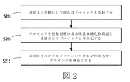
図2は、基材上に直接に噴射蒸着する方式のデジタル印刷プロセスにおいてUV硬化性ゲルインクなどの放射線硬化性インクを平坦化するための方法の実施形態を示している。方法は、S201で、基材上に直接にUV硬化性ゲルインクを蒸着すること、例えば、噴射することを含んでいてもよい。インクジェット印字ヘッドによりUV硬化性ゲルインクを噴射してもよい。基材は巻き取り紙などの媒体ウェブであってもよい。あるいは、基材は紙のカットシートであってもよい。 FIG. 2 illustrates an embodiment of a method for planarizing a radiation curable ink, such as a UV curable gel ink, in a digital printing process that is jet sprayed directly onto a substrate. The method may include depositing, eg, spraying, a UV curable gel ink directly on the substrate at S201. UV curable gel ink may be ejected by an ink jet print head. The substrate may be a media web such as a web. Alternatively, the substrate may be a paper cut sheet.
S201でインクを噴射した後に、方法は、UVゲル・インク平坦化装置の接触部材の親水性金属酸化物表面とゲルインクとを接触させて、ゲルインクを平坦化することを含んでいてもよい。接触部材は対向する部材と連動して、平坦化ニップを形成してもよい。印字ヘッドからプロセス方向の下流に平坦化ニップを配置してもよく、印字ヘッドにより噴射されたゲルインクを平坦化装置の平坦化ニップまで運ぶために基材を移動させてもよい。S205でインクを平坦化した後に、UV光源によるUV放射でインクを照射してもよい。インクに放射を作用させて、インクを重合させ、および/またはインク画像のインクを硬化させて、最終的に硬化された画像を生成するようにUV光源を構成してもよい。他の実施形態では、UV光源以外の放射線源で放射線硬化性ゲルインクを照射してもよく、電子ビーム装置などのシステムで放射線硬化性ゲルインクを照射してもよい。 After ejecting the ink in S201, the method may include planarizing the gel ink by contacting the hydrophilic metal oxide surface of the contact member of the UV gel / ink planarizing device with the gel ink. The contact member may cooperate with the opposing member to form a flattening nip. A flattening nip may be located downstream from the printhead in the process direction, and the substrate may be moved to carry the gel ink ejected by the printhead to the flattening nip of the flattening device. After flattening the ink in S205, the ink may be irradiated with UV radiation from a UV light source. The UV light source may be configured to apply radiation to the ink to polymerize the ink and / or cure the ink of the ink image to produce a final cured image. In other embodiments, the radiation curable gel ink may be irradiated with a radiation source other than the UV light source, and the radiation curable gel ink may be irradiated with a system such as an electron beam device.
図3は、基材上に直接に噴射蒸着する方式のデジタル印刷プロセスにおいてUV硬化性ゲルインクを平坦化するための方法の他の実施形態を示している。図3に示すように、方法は、S301で、基材上に直接にUV硬化性ゲルインクを噴射することを含んでいてもよい。基材は巻き取り紙などの媒体ウェブであってもよい。あるいは、基材はカットシートであってもよい。S305で、UV光源は、基材上に噴射されたUV硬化性ゲルインクに放射を作用させてもよい。放射はインクの粘度を調節してもよい。詳細には、S305でインクを固めてもよい。平坦化部材または他の表面上にインクが裏移りするのを最小限に抑えたり、または防止したりするために、インクを固めてもよい。 FIG. 3 illustrates another embodiment of a method for planarizing UV curable gel ink in a digital printing process in which it is spray deposited directly onto a substrate. As shown in FIG. 3, the method may include, at S301, jetting UV curable gel ink directly onto the substrate. The substrate may be a media web such as a web. Alternatively, the substrate may be a cut sheet. In S305, the UV light source may cause radiation to act on the UV curable gel ink ejected onto the substrate. The radiation may adjust the viscosity of the ink. Specifically, the ink may be hardened in S305. The ink may be hardened to minimize or prevent the ink from settling on the planarizing member or other surface.
固められたインクと基材とを平坦化ニップまで前進させて、平坦化してもよい。平坦化ロールなどの接触部材と、例えば、ロールなどの対向する部材とが、ニップを形成してもよい。平坦化ロールは、S301で基材上に噴射され、S305で固められたUV硬化性ゲルインクと接触するための金属酸化物表面を含んでいる。金属酸化物の接触表面は酸化クロムを含んでいてもよい。接触表面は二酸化チタンを含むことが好ましい可能性がある。接触部材の表面上に金属酸化物をプラズマ溶射して、研摩して、つや出しすることにより、金属酸化物表面を形成して、多孔質のきめ細かい金属酸化物母材を生成してもよい。S310で、接触部材は、基材上に噴射されUV光源により固められたインクと接触して、インクを平坦化してもよい。平坦化されたインクをUV光源まで前進させて、ゲルインクを硬化してもよい。例えば、基材上の平坦化されたインク画像に放射を作用させて、最終的に硬化されたUV硬化性ゲルインク画像を生成してもよい。 The solidified ink and substrate may be advanced to the flattening nip to flatten. A contact member such as a flattening roll and an opposing member such as a roll may form a nip. The flattening roll includes a metal oxide surface for contacting the UV curable gel ink that was sprayed onto the substrate at S301 and hardened at S305. The contact surface of the metal oxide may contain chromium oxide. It may be preferred that the contact surface comprises titanium dioxide. A metal oxide surface may be formed by plasma spraying, polishing, and polishing a metal oxide on the surface of the contact member to produce a porous fine metal oxide base material. In S310, the contact member may come into contact with the ink ejected onto the base material and hardened by the UV light source to flatten the ink. The planarized ink may be advanced to a UV light source to cure the gel ink. For example, radiation may be applied to the planarized ink image on the substrate to produce a final cured UV curable gel ink image.
図4は、基材上に直接に噴射蒸着する方式のデジタル印刷プロセスにおいてUV硬化性ゲルインクを平坦化するための方法の他の実施形態を示している。図4に示すように、方法は、S401で、基材上に直接にUV硬化性ゲルインクを噴射することを含んでいてもよい。基材は巻き取り紙などの媒体ウェブであってもよい。あるいは、基材はカットシートであってもよい。S405で、UV光源は、基材上に噴射されたUV硬化性ゲルインクに放射を作用させてもよい。放射はインクの粘度を調節してもよい。詳細には、S405でインクの粘度を増加させてもよい。例えば、平坦化部材または他の表面上にインクが裏移りするのを最小限に抑えたり、または防止したりするために、インクを固めてもよい。 FIG. 4 illustrates another embodiment of a method for planarizing UV curable gel inks in a digital printing process with direct spray deposition on a substrate. As shown in FIG. 4, the method may include, at S401, jetting UV curable gel ink directly onto the substrate. The substrate may be a media web such as a web. Alternatively, the substrate may be a cut sheet. In S405, the UV light source may cause radiation to act on the UV curable gel ink ejected on the substrate. The radiation may adjust the viscosity of the ink. Specifically, the ink viscosity may be increased in S405. For example, the ink may be hardened to minimize or prevent the ink from settling on the planarizing member or other surface.
固められたインクと基材とを平坦化ニップまで前進させて、平坦化してもよい。平坦化ロールなどの接触部材と、例えば、ロールなどの対向する部材とが、ニップを形成してもよい。平坦化ロールは、S401で基材上に噴射され、S405で固められたUV硬化性ゲルインクと接触するための金属酸化物表面を含んでいる。金属酸化物の接触表面は酸化クロムを含んでいてもよい。接触表面は二酸化チタンを含むことが好ましい可能性がある。接触部材の表面上に金属酸化物をプラズマ溶射して、研摩して、つや出しすることにより、金属酸化物表面を形成して、水を保持して、接触部材の表面上の水性剥離流体膜の形成を容易にする多孔質のきめ細かい金属酸化物母材を生成してもよい。 The solidified ink and substrate may be advanced to the flattening nip to flatten. A contact member such as a flattening roll and an opposing member such as a roll may form a nip. The flattening roll includes a metal oxide surface for contacting the UV curable gel ink that was sprayed onto the substrate at S401 and hardened at S405. The contact surface of the metal oxide may contain chromium oxide. It may be preferred that the contact surface comprises titanium dioxide. Plasma spraying a metal oxide on the surface of the contact member, polishing and polishing to form a metal oxide surface, retaining water, and forming an aqueous stripping fluid film on the surface of the contact member. A porous fine metal oxide matrix that facilitates formation may be produced.
S407で、接触部材の表面に剥離流体を付加してもよい。剥離流体は水性流体であってもよい。例示的剥離流体がSDSであってもよく、または例示的剥離流体は、SILGAURDのような、高分子を含む剥離流体であることが好ましい可能性がある。剥離流体は、水溶性短鎖シリコーン、界面活性剤を含む水、消泡剤、および犠牲剥離層を形成するのに適した他の流体を含んでいてもよい。 In S407, a peeling fluid may be added to the surface of the contact member. The stripping fluid may be an aqueous fluid. The exemplary release fluid may be SDS, or the exemplary release fluid may be preferably a release fluid that includes a polymer, such as SILGAURD. The release fluid may include water soluble short chain silicones, water with surfactants, antifoam agents, and other fluids suitable for forming a sacrificial release layer.
剥離流体システムが、接触部材の接触表面上に犠牲剥離層を形成するための剥離流体を、接触表面上に含み、および/または接触表面上に蒸着してもよい。S410で、接触部材の表面上に付加された犠牲剥離流体を有する接触部材は、基材上に噴射されUV光源により固められたインクと接触して、インクを平坦化してもよい。S415で、平坦化されたインクを硬化させてもよい。 A release fluid system may include and / or deposit a release fluid on the contact surface to form a sacrificial release layer on the contact surface of the contact member. In S410, the contact member having the sacrificial release fluid added on the surface of the contact member may come into contact with the ink ejected onto the substrate and hardened by the UV light source to planarize the ink. In S415, the flattened ink may be cured.
S410で、接触部材は、基材上に噴射されUV光源により固められたインクと接触して、インクを平坦化してもよい。平坦化されたインクを他のUV光源まで前進させて、ゲルインクを硬化してもよい。例えば、基材上の平坦化されたインク画像に放射を作用させて、最終的に硬化されたUV硬化性ゲルインク画像を生成してもよい。 In S410, the contact member may come into contact with the ink ejected onto the substrate and hardened by the UV light source to flatten the ink. The planarized ink may be advanced to other UV light sources to cure the gel ink. For example, radiation may be applied to the planarized ink image on the substrate to produce a final cured UV curable gel ink image.
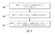
図5は、平坦化装置と、UVゲルインクの基材上に直接に噴射蒸着する方式の・デジタル印刷システムと、の接触部材の接触表面を形成するためのプロセスを示している。詳細には、図5は、S501で、円筒形平坦化ロールなどの接触部材の表面を金属酸化物粒子でプラズマ溶射することを示している。例えば、平坦化ロールの表面上に酸化クロムを溶射してもよい。平坦化ロールの表面上に二酸化チタンをプラズマ溶射することが好ましい可能性がある。 FIG. 5 shows the process for forming the contact surface of the contact member of the planarizing device and the digital printing system with direct jet deposition on the UV gel ink substrate. Specifically, FIG. 5 shows that in S501, the surface of a contact member such as a cylindrical flattening roll is plasma sprayed with metal oxide particles. For example, chromium oxide may be sprayed on the surface of the flattening roll. It may be preferable to plasma spray titanium dioxide on the surface of the flattening roll.
S501で、平坦化ロールなどの接触部材の表面上に金属酸化物をプラズマ溶射した後に、S510で、接触部材の表面上に蒸着した金属酸化物を研摩してもよい。その後、S515で、接触部材の表面上に蒸着した金属酸化物をつや出ししてもよく、これにより、金属酸化物はきめ細かい多孔質母材を形成する。毛細管現象により、保水性が高く、膜を形成する接触部材表面の形成に役立つように多孔質母材を形成してもよい。例えば、接触部材は約25ミクロンの厚さを有する金属酸化物セラミック表面を含んでいてもよい。プラズマ溶射した金属酸化物の粒径が、約5ミクロン以下であってもよい。 After the metal oxide is plasma sprayed on the surface of the contact member such as a flattening roll in S501, the metal oxide deposited on the surface of the contact member may be polished in S510. Thereafter, in S515, the metal oxide deposited on the surface of the contact member may be polished, whereby the metal oxide forms a fine porous base material. A porous base material may be formed so as to have a high water retention property by capillary action and help to form a contact member surface that forms a film. For example, the contact member may include a metal oxide ceramic surface having a thickness of about 25 microns. The particle size of the plasma sprayed metal oxide may be about 5 microns or less.
Claims (19)
放射線硬化性ゲルインク画像を形成するために印字ヘッドから直接に前記放射線硬化性ゲルインクを基材上に噴射すること、及び
前記基材上に噴射された前記放射線硬化性ゲルインクを、金属酸化物から成る接触表面を有する接触部材と直接接触させること、
を含む、前記方法。 A radiation curable gel ink flattening method comprising:
Injecting said radiation curable gel ink onto a substrate directly from the print head to form a radiation-curable gel ink image, and the radiation curable gel ink which is jetted onto the substrate, made of a metal oxide Direct contact with a contact member having a contact surface;
Said method.
請求項1に記載の方法。 Further comprising applying UV radiation to the gel ink to increase the viscosity of the radiation curable ink, the ink being UV curable;
The method of claim 1.
請求項1に記載の方法。 Further comprising applying UV radiation to the gel ink prior to contacting the ink with the contact member, the ink being UV curable;
The method of claim 1.
請求項1に記載の方法。 Before bringing the gel ink into contact with the contact member, the method further comprises adding an aqueous sacrificial release fluid to the surface of the contact member, wherein the aqueous sacrificial release fluid is at least one of a surfactant and a polymer compound. The surface of the contact member is hydrophilic,
The method of claim 1.
放射線硬化性ゲルインク平坦化装置。 A contact member having a contact surface in contact with the gel ink on the substrate after the gel ink has been directly sprayed onto the substrate and prior to final curing of the gel ink, the contact surface comprising a metal oxide ,
Radiation curable gel ink flattening device.
請求項9に記載の装置。 Further comprising a radiation source,
The apparatus according to claim 9.
印刷プロセスにおいて前記接触部材が前記基材上の前記ゲルインクと接触した後に、前記ゲルインクを硬化させるように構成された第2の放射線源と、をさらに含む、
請求項9に記載の装置。 A first radiation source configured to increase the viscosity of the jetted gel ink before the contact member contacts the gel ink on the substrate in a printing process;
A second radiation source configured to cure the gel ink after the contact member contacts the gel ink on the substrate in a printing process;
The apparatus according to claim 9.
請求項9に記載の装置。 An ink jet print head, the print head being configured to eject the gel ink directly onto the substrate;
The apparatus according to claim 9.
ゲルインク画像を形成するために放射線硬化性ゲルインクを直接に基材上に噴射するように構成されているインクジェット印字ヘッドと、
平坦化装置であって、該平坦化装置は接触部材を含み、該接触部材は前記基材上の前記ゲルインクと接触するように構成され、該接触部材は親水性の接触表面を含み、該接触表面は金属酸化物から成る、前記平坦化装置と、
前記接触表面が前記ゲルインクと接触する前に、水性の剥離流体を前記接触表面に添加する、犠牲剥離流体システムと、
を含む、前記システム。 A system for digitally printing radiation curable gel ink directly on a substrate,
An inkjet printhead configured to spray radiation curable gel ink directly onto a substrate to form a gel ink image;
A flattening device, wherein the flattening device includes a contact member, the contact member configured to contact the gel ink on the substrate, the contact member including a hydrophilic contact surface, and the contact The planarizing device, the surface comprising a metal oxide;
A sacrificial release fluid system that adds an aqueous release fluid to the contact surface before the contact surface contacts the gel ink;
Including the system.
請求項17に記載のシステム。 Further comprising a UV source configured to cure the gel ink after the contact member contacts the gel ink, the gel ink being UV curable;
The system of claim 17.
請求項17に記載のシステム。 A UV source configured to cause UV radiation to act on the gel ink before the contact member contacts the gel ink;
The system of claim 17.
Applications Claiming Priority (2)
| Application Number | Priority Date | Filing Date | Title |
|---|---|---|---|
| US13/173,492 | 2011-06-30 | ||
| US13/173,492 US8419179B2 (en) | 2011-06-30 | 2011-06-30 | Methods for UV gel ink leveling and direct-to-substrate digital radiation curable gel ink printing, apparatus and systems having leveling member with a metal oxide surface |
Publications (3)
| Publication Number | Publication Date |
|---|---|
| JP2013014137A JP2013014137A (en) | 2013-01-24 |
| JP2013014137A5 JP2013014137A5 (en) | 2015-08-13 |
| JP5863576B2 true JP5863576B2 (en) | 2016-02-16 |
Family
ID=47355343
Family Applications (1)
| Application Number | Title | Priority Date | Filing Date |
|---|---|---|---|
| JP2012141875A Expired - Fee Related JP5863576B2 (en) | 2011-06-30 | 2012-06-25 | Method, apparatus and system for digital radiation curable gel ink printing with UV gel ink planarization and jet deposition directly on a substrate having a planarizing member with a metal oxide surface |
Country Status (4)
| Country | Link |
|---|---|
| US (1) | US8419179B2 (en) |
| JP (1) | JP5863576B2 (en) |
| CN (1) | CN102848769B (en) |
| DE (1) | DE102012210451A1 (en) |
Families Citing this family (3)
| Publication number | Priority date | Publication date | Assignee | Title |
|---|---|---|---|---|
| US8628177B2 (en) * | 2011-08-01 | 2014-01-14 | Xerox Corporation | Methods, apparatus, and systems for spreading radiation curable gel ink |
| US8931890B2 (en) * | 2012-06-15 | 2015-01-13 | Xerox Corporation | Method and apparatus for leveling a printed image and preventing image offset |
| US9677999B2 (en) * | 2014-03-26 | 2017-06-13 | Board Of Regents, The University Of Texas System | Cavity enhancement methods, systems and devices, and methods of measuring same |
Family Cites Families (14)
| Publication number | Priority date | Publication date | Assignee | Title |
|---|---|---|---|---|
| DE4447178A1 (en) * | 1994-12-30 | 1996-07-04 | Koenig & Bauer Albert Ag | Dampening unit for a printing press |
| US6820975B2 (en) * | 2000-09-01 | 2004-11-23 | Konica Corporation | Inkjet recording apparatus and inkjet recording method |
| US20030205059A1 (en) * | 2002-05-02 | 2003-11-06 | Hussmann Corporation | Merchandisers having anti-fog coatings and methods for making the same |
| US7510277B2 (en) * | 2004-03-01 | 2009-03-31 | Fujifilm Corporation | Image forming apparatus and method |
| JP4006416B2 (en) * | 2004-06-03 | 2007-11-14 | キヤノン株式会社 | Inkjet recording method and inkjet recording apparatus |
| DE602008006279D1 (en) * | 2007-02-07 | 2011-06-01 | Fujifilm Corp | An ink jet recording apparatus having an ink jet printhead maintenance device and an ink jet printhead maintenance method |
| JP2010536615A (en) * | 2007-08-20 | 2010-12-02 | ムーア ウォリス ノース アメリカ、 インコーポレーテッド | Inkjet printing apparatus and inkjet printing method |
| US8231214B2 (en) * | 2008-10-23 | 2012-07-31 | Xerox Corporation | Method and apparatus for fixing a radiation-curable gel-ink image on a substrate |
| US20100141720A1 (en) * | 2008-12-09 | 2010-06-10 | Palo Alto Research Center Incorporated | Spreading and leveling of curable gel ink |
| US8334026B2 (en) * | 2009-05-29 | 2012-12-18 | Xerox Corporation | Tunable fluorescent UV curable gel inks containing fluorescent monomers for food packaging applications |
| US8121528B2 (en) * | 2009-06-24 | 2012-02-21 | Xerox Corporation | Apparatuses useful for printing and methods of treating marking material on media |
| US8268399B2 (en) * | 2009-08-19 | 2012-09-18 | Xerox Corporation | Polyhedral oligomeric silsesquioxane image conditioning coating |
| US8041245B2 (en) * | 2009-08-31 | 2011-10-18 | Xerox Corporation | Apparatuses useful in printing and methods of controlling the temperature of surfaces in apparatuses useful in printing |
| US8096649B2 (en) * | 2009-11-24 | 2012-01-17 | Xerox Corporation | Image conditioning coating |
-
2011
- 2011-06-30 US US13/173,492 patent/US8419179B2/en not_active Expired - Fee Related
-
2012
- 2012-06-21 DE DE102012210451A patent/DE102012210451A1/en not_active Withdrawn
- 2012-06-25 JP JP2012141875A patent/JP5863576B2/en not_active Expired - Fee Related
- 2012-06-29 CN CN201210220332.1A patent/CN102848769B/en not_active Expired - Fee Related
Also Published As
| Publication number | Publication date |
|---|---|
| JP2013014137A (en) | 2013-01-24 |
| DE102012210451A1 (en) | 2013-01-03 |
| CN102848769A (en) | 2013-01-02 |
| US20130002770A1 (en) | 2013-01-03 |
| US8419179B2 (en) | 2013-04-16 |
| CN102848769B (en) | 2015-05-13 |
Similar Documents
| Publication | Publication Date | Title |
|---|---|---|
| JP6632334B2 (en) | Intermediate transfer member and image forming method | |
| EP1919711B1 (en) | Method of printing | |
| EP2387504B1 (en) | Digital cliché pad printing system and method | |
| WO2007145378A1 (en) | Method for producing record product, and intermediate transfer body and image recording apparatus used therefor | |
| US6520084B1 (en) | Method for making printing plate using inkjet | |
| JP6470663B2 (en) | Image marking apparatus, image forming method on image receiving medium substrate, and image forming system | |
| US20070065571A1 (en) | Method and apparatus for manufacturing a pixel matrix of a color filter for a flat panel display | |
| JP5863576B2 (en) | Method, apparatus and system for digital radiation curable gel ink printing with UV gel ink planarization and jet deposition directly on a substrate having a planarizing member with a metal oxide surface | |
| JP2767796B2 (en) | Ink jet printer | |
| JP5335525B2 (en) | Lipophilic pattern forming method and coating roller obtained by the method | |
| JP4189421B2 (en) | Direct-drawing printing original plate, method for producing the same, and plate making method using the same | |
| DE102005052156A1 (en) | Method for gravure print by means of detachable and reusable gravure cylinder, involves basic grid designed on maximal color quantity and impression of basic grid of gravure blank shape are simultaneously filled with filling material | |
| US8197054B2 (en) | Image fixing method, method for producing record product using such method, and image recording apparatus | |
| JP5921362B2 (en) | Method for leveling radiation curable gel ink and digital printing directly on a substrate of radiation curable gel ink and apparatus and system having a pressure member with a hydrophobic surface | |
| JP2003136697A (en) | Recorder | |
| JP2015024504A (en) | Image recording method | |
| JP6296901B2 (en) | Method for manufacturing three-dimensional object and apparatus for manufacturing the same | |
| JP2005028813A (en) | Platemaking device | |
| JP4436037B2 (en) | Printing master, plate making apparatus, printing apparatus, and printing method | |
| CN108700803A (en) | The method that production manufactures relief printing plate is spread by the monomer through whole mask layer | |
| JP6345038B2 (en) | Image forming method and image forming apparatus | |
| JP2020192702A (en) | Intermediate transfer body, image formation method and image formation device | |
| JP2010069796A (en) | Recording apparatus | |
| JP2018161846A (en) | Building board and manufacturing method therefor | |
| JP2014097608A (en) | Image recording method |
Legal Events
| Date | Code | Title | Description |
|---|---|---|---|
| A521 | Request for written amendment filed |
Free format text: JAPANESE INTERMEDIATE CODE: A523 Effective date: 20150625 |
|
| A621 | Written request for application examination |
Free format text: JAPANESE INTERMEDIATE CODE: A621 Effective date: 20150625 |
|
| A871 | Explanation of circumstances concerning accelerated examination |
Free format text: JAPANESE INTERMEDIATE CODE: A871 Effective date: 20150625 |
|
| A975 | Report on accelerated examination |
Free format text: JAPANESE INTERMEDIATE CODE: A971005 Effective date: 20150729 |
|
| A131 | Notification of reasons for refusal |
Free format text: JAPANESE INTERMEDIATE CODE: A131 Effective date: 20150803 |
|
| A521 | Request for written amendment filed |
Free format text: JAPANESE INTERMEDIATE CODE: A523 Effective date: 20151104 |
|
| TRDD | Decision of grant or rejection written | ||
| A01 | Written decision to grant a patent or to grant a registration (utility model) |
Free format text: JAPANESE INTERMEDIATE CODE: A01 Effective date: 20151124 |
|
| A61 | First payment of annual fees (during grant procedure) |
Free format text: JAPANESE INTERMEDIATE CODE: A61 Effective date: 20151222 |
|
| R150 | Certificate of patent or registration of utility model |
Ref document number: 5863576 Country of ref document: JP Free format text: JAPANESE INTERMEDIATE CODE: R150 |
|
| R250 | Receipt of annual fees |
Free format text: JAPANESE INTERMEDIATE CODE: R250 |
|
| R250 | Receipt of annual fees |
Free format text: JAPANESE INTERMEDIATE CODE: R250 |
|
| LAPS | Cancellation because of no payment of annual fees |