JP5863376B2 - Wiring box - Google Patents
Wiring box Download PDFInfo
- Publication number
- JP5863376B2 JP5863376B2 JP2011225116A JP2011225116A JP5863376B2 JP 5863376 B2 JP5863376 B2 JP 5863376B2 JP 2011225116 A JP2011225116 A JP 2011225116A JP 2011225116 A JP2011225116 A JP 2011225116A JP 5863376 B2 JP5863376 B2 JP 5863376B2
- Authority
- JP
- Japan
- Prior art keywords
- step portion
- connection
- box
- conduit
- high step
- Prior art date
- Legal status (The legal status is an assumption and is not a legal conclusion. Google has not performed a legal analysis and makes no representation as to the accuracy of the status listed.)
- Active
Links
- 238000003780 insertion Methods 0.000 claims description 94
- 230000037431 insertion Effects 0.000 claims description 94
- 230000002093 peripheral effect Effects 0.000 claims description 25
- 230000015572 biosynthetic process Effects 0.000 claims description 7
- 230000000694 effects Effects 0.000 description 8
- 239000000463 material Substances 0.000 description 3
- 229920003002 synthetic resin Polymers 0.000 description 2
- 239000000057 synthetic resin Substances 0.000 description 2
- 238000004925 denaturation Methods 0.000 description 1
- 230000036425 denaturation Effects 0.000 description 1
- 238000009434 installation Methods 0.000 description 1
- 238000000034 method Methods 0.000 description 1
- 238000012986 modification Methods 0.000 description 1
- 230000004048 modification Effects 0.000 description 1
- 230000000149 penetrating effect Effects 0.000 description 1
- 238000009751 slip forming Methods 0.000 description 1
- 230000001629 suppression Effects 0.000 description 1
Images


Description
本発明は、配線器具等を収容し、その配線器具に接続されたケーブルを保護するために電線管が接続される配線ボックスに関する。 The present invention relates to a wiring box in which a conduit is connected to accommodate a wiring device or the like and protect a cable connected to the wiring device.
従来より、例えば建物内の壁面に配線器具等を設置するため、その壁内には配線ボックスが設置されている。その配線ボックスにはケーブルが引込まれ、そのケーブルは、配線ボックスの接続部に接続された電線管により保護されている。この電線管を接続するために、該配線ボックスの四隅には、接続部と連通する挿入開口を形成している。 Conventionally, for example, a wiring box is installed in a wall in order to install a wiring device or the like on a wall surface in a building. A cable is drawn into the wiring box, and the cable is protected by a conduit connected to a connection portion of the wiring box. In order to connect this conduit, insertion openings communicating with the connection portions are formed at the four corners of the wiring box.
ところが、各挿入開口が、独立して配線ボックスの外方に向かって開口していると、例えば、配線ボックスを柱に固定した後や、柱の近傍に障害物が存在する場所に配線ボックスを設置する場合、柱や障害物によって挿入開口への電線管の挿入が阻害されてしまい、配線ボックスにおける柱や障害物寄りの接続部には電線管を接続できない。 However, if each insertion opening is opened to the outside of the wiring box independently, for example, after the wiring box is fixed to the pillar, or in a place where an obstacle exists in the vicinity of the pillar. When installing, the insertion of the conduit into the insertion opening is hindered by the pillar and the obstacle, and the conduit cannot be connected to the connection portion near the pillar or the obstacle in the wiring box.
そこで、配線ボックスにおける柱や障害物寄りに電線管を接続可能とした配線ボックスとして、例えば、特許文献1が挙げられる。特許文献1に開示の配線ボックス80では、図8に示すように、ボックス本体81の上側壁81a及び下側壁81bに、電線管90の接続部82を形成している。接続部82は、上側壁81a及び下側壁81bの長さ方向の略全体に延びる長孔状をなす接続孔83と、その接続孔83の内面に形成された係合突条84とより構成されている。また、ボックス本体81の右側壁81cの上下両側には挿入開口85が形成され、その挿入開口85は接続孔83と連通している。すなわち、接続部82には、その長さ方向の一端側のみに接続孔83が形成されている。そして、配線ボックス80の挿入開口85に電線管90が挿入されるとともに、電線管90を係合突条84に係合させつつ接続孔83に沿ってスライド移動させることにより接続部82に電線管90が接続される。よって、柱や障害物などが配線ボックス80の左側にあっても、その柱や障害物側に向けて電線管90をスライドさせることにより、配線ボックス80の柱や障害物側に電線管90を接続することができる。
Thus, for example,
ところで、特許文献1に開示の配線ボックス80では、接続孔83を上側壁81a及び下側壁81bの長辺方向に延ばすことで、複数本(この例では2本)の電線管90を1つの接続部82に接続可能にしている。しかしながら、異なる径の電線管90を1つの接続部82に接続する場合など、その接続部82の開口幅が電線管90の径と合わなければ、接続部82への各電線管90の接続状態が不安定になってしまう。よって、配線ボックスとしては、1つの接続部82に複数本の電線管90を接続するよりも、1つの接続部82に1本の電線管90を接続した方が好ましい。
By the way, in the
本発明は、前記従来の問題に鑑みてなされたものであって、その目的は、柱や障害物によって電線管の挿入が阻害されることなく、電線管を接続部に接続することができる配線ボックスを提供することにある。 The present invention has been made in view of the above-described conventional problems, and the object thereof is wiring capable of connecting a conduit to a connecting portion without hindering insertion of the conduit by a pillar or an obstacle. To provide a box.
上記問題点を解決するために、請求項1に記載の発明は、周壁によって一面に開口を有する多角箱状に形成されるとともに、内部にケーブルが挿通される電線管を接続可能な接続部が形成されたボックス本体を備え、前記ボックス本体の周壁に高段部と低段部とによって構成される段差が形成され、前記高段部には、前記接続部が形成されるとともに、前記低段部側に開口し、前記接続部に連通する挿入開口が形成されてなり、前記接続部は、前記低段部にも形成されることを要旨とする。
In order to solve the above problem, the invention according to
請求項2に記載の発明は、周壁によって一面に開口を有する多角箱状に形成されるとともに、内部にケーブルが挿通される電線管を接続可能な接続部が形成されたボックス本体を備え、前記ボックス本体の周壁に高段部と低段部とによって構成される段差が形成され、前記高段部には、前記接続部が形成されるとともに、前記低段部側に開口し、前記接続部に連通する挿入開口が形成されてなり、前記高段部に形成された前記挿入開口は、前記ボックス本体の角部から離れた位置に形成されてなることを要旨とする。
請求項3に記載の発明は、周壁によって一面に開口を有する多角箱状に形成されるとともに、内部にケーブルが挿通される電線管を接続可能な接続部が形成されたボックス本体を備え、前記ボックス本体の周壁に高段部と低段部とによって構成される段差が形成され、前記高段部には、前記接続部が形成されるとともに、前記低段部側に開口し、前記接続部に連通する挿入開口が形成されてなり、前記挿入開口は、前記ボックス本体が固定される構造物と当接する当接座部の形成位置と反対側に開口してなることを要旨とする。
The invention according to claim 2 is provided with a box main body formed with a connection portion capable of connecting a conduit tube through which a cable is inserted while being formed in a polygonal box shape having an opening on one surface by a peripheral wall, A step formed by a high step portion and a low step portion is formed on the peripheral wall of the box body, and the connection portion is formed in the high step portion, and the connection portion is opened to the low step portion side. The gist of the present invention is that the insertion opening formed in the high step portion is formed at a position away from the corner portion of the box body .
The invention according to claim 3 is provided with a box main body formed with a connection portion capable of connecting a conduit tube through which a cable is inserted while being formed in a polygonal box shape having an opening on one surface by a peripheral wall, A step formed by a high step portion and a low step portion is formed on the peripheral wall of the box body, and the connection portion is formed in the high step portion, and the connection portion is opened to the low step portion side. An insertion opening that communicates with the box body is formed, and the insertion opening is formed on the side opposite to the formation position of the contact seat portion that contacts the structure to which the box body is fixed .
請求項4に記載の発明は、請求項3に記載の配線ボックスにおいて、前記高段部は、複数形成されており、前記高段部に連通する挿入開口は、前記ボックス本体が固定される構造物と当接する当接座部の形成位置と反対側に開口してなることを要旨とする。
According to a fourth aspect of the present invention, in the wiring box according to the third aspect , a plurality of the high step portions are formed, and the insertion opening communicating with the high step portion has a structure in which the box body is fixed. The gist is that the opening is formed on the side opposite to the formation position of the abutting seat portion that abuts the object .
請求項5に記載の発明は、請求項4に記載の配線ボックスにおいて、前記当接座部に近い高段部ほどその段が高くなるように形成されていることを要旨とする。
請求項6に記載の発明は、周壁によって一面に開口を有する多角箱状に形成されるとともに、内部にケーブルが挿通される電線管を接続可能な接続部が形成されたボックス本体を備え、前記ボックス本体の周壁に高段部と低段部とによって構成される段差が形成され、前記高段部には、前記接続部が形成されるとともに、前記低段部側に開口し、前記接続部に連通する挿入開口が形成されてなり、前記周壁には、前記高段部が少なくとも2つ形成され、2つの高段部の間に前記低段部が形成され、前記2つの高段部にそれぞれ形成された前記挿入開口が相対向し、前記2つの高段部のうちの一方の接続部に前記電線管が接続されている状態であっても、前記低段部によって他方の接続部への前記電線管の挿入が許容されることを要旨とする。
The gist of the invention according to claim 5 is that the wiring box according to
The invention according to claim 6 is provided with a box body formed with a connecting portion capable of connecting a conduit tube through which a cable is inserted, and formed into a polygonal box shape having an opening on one surface by a peripheral wall, A step formed by a high step portion and a low step portion is formed on the peripheral wall of the box body, and the connection portion is formed in the high step portion, and the connection portion is opened to the low step portion side. An insertion opening that communicates with the peripheral wall, and at least two of the high step portions are formed on the peripheral wall, and the low step portion is formed between the two high step portions. Even when the insertion openings formed respectively face each other and the conduit is connected to one of the two high-stage parts, the low-stage part leads to the other connection part. The gist of the present invention is that insertion of the conduit is allowed .
請求項7に記載の発明は、請求項1から6のいずれか一項に記載の配線ボックスにおいて、前記ボックス本体の角部に隣接する段部に形成されている接続部には、前記ボックス本体の側壁に形成された挿入開口が連通されてなることを要旨とする。
The invention according to
請求項8に記載の発明は、請求項1から7のいずれか一項に記載の配線ボックスにおいて、1つの高段部には、接続部が2つ形成されてなることを要旨とする。
The gist of the invention described in claim 8 is that, in the wiring box according to any one of
本発明によれば、柱や障害物で電線管の挿入が阻害されることなく、電線管を接続部に接続することができる。 According to the present invention, it is possible to connect the conduit to the connection portion without hindering insertion of the conduit by a pillar or an obstacle.
(第1実施形態)
以下、本発明を配線ボックスに具体化した第1実施形態を図1及び図2に従って説明する。
(First embodiment)
A first embodiment in which the present invention is embodied in a wiring box will be described below with reference to FIGS.
まず、配線ボックスに接続される電線管Dについて説明する。
図1に示すように、電線管Dは合成樹脂材料により長筒状に形成された可撓管であり、その周方向に突出する同一径のリング状をなす凸条部Daと、同一径のリング状をなす凹条部Dbとが繰り返し連続形成されて凹凸状に形成されている。そして、電線管D内には図示しないケーブルが挿通され、そのケーブルが電線管Dにより保護される。
First, the conduit D connected to the wiring box will be described.
As shown in FIG. 1, the conduit D is a flexible tube formed of a synthetic resin material in the shape of a long cylinder, and has the same diameter as the convex portion Da that forms a ring shape with the same diameter protruding in the circumferential direction. The ring-shaped concave strip portion Db is continuously formed repeatedly to form an uneven shape. A cable (not shown) is inserted into the conduit D, and the cable is protected by the conduit D.
次に、配線ボックス10について説明する。
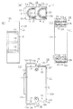
合成樹脂材料製の配線ボックス10は、有底四角箱状のボックス本体11を備えている。ボックス本体11は、矩形板状をなす底壁12と、その底壁12の上下に対向する一対の側縁から立設された上側壁12a及び下側壁12bと、底壁12の左右に対向する一致の側縁から立設された左側壁12c及び右側壁12dと、により構成されている。底壁12、側壁12a〜12dは、周壁でもある。また、底壁12における一対の短辺縁部において、左側壁12cに隣接する端部から短辺方向の略半分の位置には、上側壁12a及び下側壁12bにそれぞれ直交する延設部12eが、それぞれ延設されている。これに伴って、左側壁12cは右側壁12dよりも長く形成されている。また、上側壁12aの長辺方向における略左半分までの位置には、左側壁12c及び上側壁12aと直交するとともに、側壁12aから右側壁12dの立設位置と並行する位置まで延びる延設部12fが延設されている。同様に、下側壁12bの長辺方向における略左半分までの位置には、左側壁12c及び下側壁12bと直交するとともに、側壁12bから右側壁12dの立設位置と並行する位置まで延びる延設部12fが延設されている。この延設部12fによって、ボックス本体11の開口部Kは、略長方形状をなす。なお、開口部K側をボックス本体11の前面(正面)とし、底壁12側をボックス本体11の後面(背面)とする。
Next, the
A
図1及び図2(b)に示すように、左側壁12cの外面には、一定の厚みを有する当接座部13が外方へ突出形成されている。また、左側壁12cには、左側壁12cを貫通する固定孔14が、ボックス本体11の奥行き方向へ長孔状に延びるように複数個所(この例では3箇所)に形成され、各固定孔14は、それぞれ固定ビス15を挿通可能に形成されている。固定孔14に挿通された固定ビス15が構造物としての柱Hに固定されることにより、柱Hと当接座部13が当接し、その結果、配線ボックス10が柱Hに固定される。
As shown in FIG.1 and FIG.2 (b), the
図1及び図2(d)に示すように、上側壁12a及び下側壁12bには、延設部12e,12fが設けられたボックス本体11の形状を利用して、ボックス本体11の外方に向かって突出する段差16がそれぞれ設けられている。そして、上側壁12a及び下側壁12bには、段差16のうち高い側に高段部16aが形成され、低い側に右側壁12dの立設位置と同じ高さに設けられた低段部16bが形成されている。なお、「高段部」と「低段部」は、2つの段部を比較した場合、相対的に高い方が「高段部」となる一方で、相対的に低い方が「低段部」となる。したがって、例えば、3つの段部が階段状に配置されている場合、中央の段部は、最も高い段部と比較すると「低段部」となるが、最も低い段部と比較すると「高段部」となる。また、段差16は、底壁12の長辺方向に沿った長さを略等分する中心線L(図1参照)を対称として、上下対称となるようにそれぞれ形成されている。
As shown in FIGS. 1 and 2 (d), the
そして、高段部16aと低段部16bには、接続部としての接続孔17,18が形成されるとともに、接続孔17,18は、右側壁12dに向かって開口している。
また、図1及び図2(a),(c)に示すように、各接続孔17,18の内周に沿って第1係合突条19が形成されている。各第1係合突条19はそれぞれ接続孔17,18の挿入開口22,23側から接続孔17,18の奥方に向かって直線状に延び、さらに接続孔17,18の円弧に沿って延びるように形成されている。また、各第1係合突条19の内周に沿って、接続部材21を介して第2係合突条20が形成されている。各第2係合突条20はそれぞれ接続孔17,18の挿入開口22,23側から接続孔17,18の奥方に向かって直線状に延び、さらに第1係合突条19の円弧に沿って延びるように形成されている。
And the connection holes 17 and 18 as a connection part are formed in the
Further, as shown in FIGS. 1 and 2A and 2C, a
また、高段部16aには、挿入開口22が、低段部16b側に向かって開口するとともに接続孔17と連通するように形成されている。この挿入開口22は、電線管Dを接続孔17にガイドする。一方、低段部16bにおいて、該低段部16bと直交する右側壁12dの上下両端部、すなわち、配線ボックス10の右角部には、挿入開口23が、右側壁12dの外方に向かって開口するとともに接続孔18と連通するように形成されている。また、挿入開口22,23の側壁12a,12bの短辺方向への開口幅は電線管Dの凸条部Daにおける外径と同じ又はわずかに大きく形成されている。
Further, the
このように、挿入開口22,23を形成したことで、接続孔17,18は、当接座部13と反対側に開口していることになる。また、高段部16aにおける側壁12a,12bの長辺方向への長さと、低段部16bにおける側壁12a,12bの長辺方向への長さは、略同一の長さであって、かつ各挿入開口22,23の開口面積も略同一である。これにより、各接続孔17,18に電線管Dを接続するまでのストロークは、高段部16a及び低段部16bにおいて略同一となる。
Thus, by forming the
また、接続孔17,18の開口幅は、電線管Dの凸条部Daにおける外径よりわずかに短く形成されている。そして、第2係合突条20は、接続部材21をペンチなどによって第1係合突条19から取り外すことで、取り外し可能に構成されている。これにより、挿入される電線管Dの径に合わせて、接続孔17,18の開口幅を調節することができる。すなわち、電線管Dが挿入開口22,23から接続孔17,18内に挿入されると、その電線管Dの径の違いに応じて、電線管Dの凹条部Dbに第1係合突条19又は第2係合突条20を係合させることが可能となっている。
Further, the opening widths of the connection holes 17 and 18 are formed slightly shorter than the outer diameter of the convex portion Da of the conduit D. And the
次に、上記構成の配線ボックス10の作用を設置方法と共に説明する。なお、以下の説明では、2本の電線管Dを接続孔17,18にそれぞれ接続するものとして説明する。また、以下の説明では、第1係合突条19によって係合される径の電線管Dを使用するものとして説明する。
Next, the operation of the
まず、ボックス本体11の開口端が、柱Hの前面と同一平面となるように、当接座部13の外面を柱Hの側面に当接させる。そして、左側壁12cに形成された固定孔14に固定ビス15を挿通し、その固定ビス15を柱Hに固定して配線ボックス10を柱Hに固定する。このとき、接続孔17,18の挿入開口22,23は、それぞれ柱Hと反対側に向かって開口している。
First, the outer surface of the
そして、高段部16aの接続孔17から電線管Dを接続するため、電線管Dを挿入開口22の近傍に配置する。そして、そのまま電線管Dを、挿入開口22を介して接続孔17に向けて押し込むと、配線ボックス10の右側から挿入開口22に電線管Dが挿入されるとともに、凹条部Dbの外周面に第1係合突条19の内周縁が係合する。そして、電線管Dを第1係合突条19に係合させつつ接続孔17に沿ってスライド移動させることにより接続孔17に電線管Dが接続される。
And in order to connect the electric wire D from the
次に、電線管Dを低段部16bにおける挿入開口23の近傍に配置する。そして、そのまま電線管Dを、挿入開口23を介して接続孔18に向けて押し込むと、配線ボックス10の右側から挿入開口23に電線管Dが挿入されるとともに、凹条部Dbの外周面に第1係合突条19の内周縁が係合する。そして、電線管Dを第1係合突条19に係合させつつ接続孔18に沿ってスライド移動させることにより接続孔18に電線管Dが接続される。これにより、各接続孔17,18にそれぞれ電線管Dを1つずつ接続することができる。
Next, the conduit D is disposed in the vicinity of the
なお、高段部16a及び低段部16bにおいてそれぞれ1つの電線管Dを接続する接続孔17,18がそれぞれ形成されているため、一方の電線管Dが他方の電線管D側に向けて移動することが防止されている。
In addition, since the connection holes 17 and 18 which connect one conduit D are each formed in the
次に、図示しないケーブルを、電線管D内に挿入しながら配線ボックス10内に引き込む。その後、図1に示すように、柱Hの前後両側に壁材Waが立設されて、壁Wが構築されるとともに、この壁W内に配線ボックス10が設置される。
Next, a cable (not shown) is drawn into the
上記実施形態によれば、以下のような効果を得ることができる。
(1)ボックス本体11の上側壁12a及び下側壁12bに、該ボックス本体11の外方に向かって突出する段差16を形成した。そして、段差16を構成する高段部16aに、電線管Dを接続する接続孔17を形成するとともに、低段部16b側に向かって開口し、接続孔17に連通する挿入開口22を形成した。これにより、特に、配線ボックス10を柱Hに固定した後や、柱Hの近傍に障害物が存在する場所に配線ボックス10を設置する場合においても、挿入開口22が柱Hや障害物と反対側に向かって開口しているため、電線管Dを接続孔17に接続することができる。したがって、配線ボックス10に電線管Dを予め接続した状態で配線ボックス10を柱Hに固定する作業を行う必要がなくなる。ちなみに、配線ボックス10に電線管Dを接続した状態で配線ボックス10を柱Hに固定すると、電線管Dによって視認性が低下し、正確な位置に配線ボックス10を固定することができない虞がある。
According to the above embodiment, the following effects can be obtained.
(1)
(2)接続孔18を、高段部16aより低い位置にある低段部16bにも形成し、かつボックス本体11の角部に挿入開口23を形成した。低段部16bにも接続孔18を形成することで、側壁12a,12bの低段部16bを有効に利用して電線管Dを接続することができる。
(2) The
(3)高段部16aの挿入開口22を、側壁12a,12bの角部から離れた位置に形成した。このような形成位置としたことで、側壁12a,12bにおいて挿入開口22の近傍に電線管Dを配置することができるとともに、柱Hや柱Hの近傍の障害物によって、挿入開口22への電線管Dの挿入が阻害されなくなるので、電線管Dを接続孔17に接続することができる。
(3) The
(4)挿入開口22,23を、高段部16aにおいて当接座部13の形成位置と反対側に設けた。これにより、柱Hや柱Hの近傍の障害物によって、挿入開口22,23への電線管Dの挿入が阻害されることがなくなるので、どの接続孔にも電線管Dを接続することができる。
(4) The
(5)従来技術のように(図8参照)、当接座部と反対側の右側壁81cから当接座部に向かって延びる接続部82を形成するとともに、その接続部82を複数本の電線管90を接続可能となるように形成したとする。この場合、当接座部に最も近い位置に移動するまでの電線管90のストロークが大きくなり、ストロークが大きい分、余分な力が付加されて電線管90が変形してしまうなどが考えられる。ところが、高段部16aに挿入開口22を形成したことで、側壁12a,12bにおいて挿入開口22の近傍に電線管Dを配置することができる。これにより、当接座部に最も近い接続孔17に電線管Dを接続しようとする場合であっても、挿入開口22の側に電線管を配置できることから、短いストロークで電線管Dを接続することができる。その結果、ストロークが短いことで、接続孔17に到達するまでに電線管Dに余分な力が付加される時間も短縮することができるので、電線管Dの変性の抑制にも繋がる。
(5) As in the prior art (see FIG. 8), a connecting
(第2実施形態)
以下、本発明を配線ボックスに具体化した第2実施形態を図3に従って説明する。なお、以下に説明する実施形態では、既に説明した第1実施形態と同一構成については、同一符号を付すなどして、その重複する説明を省略又は簡略する。
(Second Embodiment)
A second embodiment in which the present invention is embodied in a wiring box will be described below with reference to FIG. In the embodiment described below, the same components as those in the first embodiment described above are denoted by the same reference numerals, and the redundant description thereof is omitted or simplified.
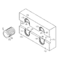
図3に示すように、第2実施形態の配線ボックス100では、側壁12a,12bの左側壁12c側の外面に高段部16aが形成されている一方で、側壁12a,12bの右側壁12d側の外面に高段部16cが形成されている。
As shown in FIG. 3, in the
高段部16a,16cは同一の高さとされる一方で、高段部16a,16cとの間には、高段部16a,16cより低い低段部16dが形成され、配線ボックス100は凹形状となっている。側壁12a,12bの長辺方向に沿った低段部16dの長さは、高段部16a,16cに形成された接続孔17,24のうちどちらかに電線管Dが接続されている状態でも、電線管Dが接続されていない接続孔17,24への挿入を許容するような長さに形成されている。
While the
高段部16aには、接続孔17が形成されるとともに、低段部16dに向かって開口し、接続孔17と連通する挿入開口22が形成されている。一方、高段部16cには、接続孔18a,24が形成されるとともに、低段部16dに向かって開口し、接続孔24と連通する挿入開口25と、右側壁12dに向かって開口し、接続孔18aと連通する挿入開口23aがそれぞれ形成されている。
A
さらに、側壁12a,12bにおいて、該側壁12a,12bの長辺縁部からは、リブ部26が延設されている。このリブ部26は、ボックス本体11の外方に向かって互いに突出するとともに、高段部16a,16cと略同じ高さまで延びる。このリブ部26によって、配線ボックス100を前面から視認した際に低段部16dを視認不能としている。
Further, in the
このように、第2実施形態の配線ボックス100は、3つの接続孔17,18a,24を備えている。そして、当接座部13に最も近い高段部16aでは、挿入開口22が、当接座部13と反対側に形成されているため、配線ボックス100を柱Hに取り付けた後でも、接続孔17に電線管Dを接続することができる。
As described above, the
また、接続孔17と接続孔24の挿入開口22,25は相対向しているが、高段部16a,16cの間には、低段部16dが形成されている。このため、接続孔17,24のうちどちらかに電線管Dが接続されている状態であっても、低段部16dにより、電線管Dが接続されていない接続孔17,24への電線管Dの挿入が許容される。また、当接座部13を用いて配線ボックス100を柱Hに固定したとき、高段部16cに形成された接続孔18aに連通する挿入開口23aの近傍には、柱Hがない。これにより、挿入順序の制限なく、接続孔17,18a,24に電線管Dを挿入することができる。
The
上記第2実施形態によれば、第1実施形態に記載の(1)〜(5)と同様の効果に加えて以下の効果を得ることができる。
(6)側壁12a,12bに2つの高段部16a,16cを設けるとともに、その間に低段部16dを設けて凹形状とした。このため、接続孔17と接続孔24の挿入開口22,25は相対向しているが、接続孔17,24のうちどちらかに電線管Dが接続されている状態であっても、低段部16dにより、電線管Dが接続されていない接続孔17,24への電線管Dの挿入が可能となる。また、当接座部13を用いて配線ボックス100を柱Hに固定したとき、高段部16cに形成された接続孔18aに連通する挿入開口23aの近傍には、柱Hがない。これにより、挿入開口22,23a,25の近傍に電線管Dを配置可能となるため、挿入順序の制限なく、接続孔17,18a,24に電線管Dを挿入することができる。
According to the said 2nd Embodiment, in addition to the effect similar to (1)-(5) as described in 1st Embodiment, the following effects can be acquired.
(6) Two high-
(7)接続孔24を側壁12a,12bの角部から離れた位置に形成したことで、挿入開口25も側壁12a,12bの角部から離れた位置に形成されることになる。そして、低段部16dを形成したことで、挿入開口25の近傍に電線管Dを配置することができるとともに、柱Hや柱Hの近傍の障害物によって、挿入開口25への電線管Dの挿入が阻害されなくなるので、電線管Dを接続孔24に接続することができる。
(7) By forming the
(8)側壁12a,12bの長辺縁部から、ボックス本体11の外方に向かって互いに突出するとともに、高段部16a,16cと略同じ高さまで延びるリブ部26を延設した。配線ボックス100を地面に直接置いたときなどであっても、このリブ部26によって、配線ボックス100の安定性を高めることができる。また、リブ部26によって、配線ボックス100自体の強度を高めることができる。さらに、リブ部26によって低段部16dが前面から視認不能となるため、デザイン性の向上に繋がる。
(8) The
(第3実施形態)
次に、本発明を配線ボックスに具体化した第3実施形態を図4に従って説明する。
図4に示すように、第3実施形態の配線ボックス110では、側壁12a,12bの外面の略中央に、1つの高段部16eが形成されている。また、側壁12a,12bにおいて、高段部16eの両側には低段部16b,16fがそれぞれ形成されている。そして、高段部16eでは、2つの接続孔27,28が形成されている。接続孔27は、当接座部13に向かって開口する形状とされている一方で、接続孔28は、右側壁12dに向かって開口する形状とされている。そして、高段部16eには、接続孔27,28にそれぞれ連通するとともに両低段部16b,16dに向かって開口する挿入開口29,30がそれぞれ形成されている。
(Third embodiment)
Next, a third embodiment in which the present invention is embodied in a wiring box will be described with reference to FIG.
As shown in FIG. 4, in the
一方、配線ボックス110では低段部16b,16fに接続孔18,31がそれぞれ形成されるとともに、低段部16bと直交する右側壁12dの上下両端部には、挿入開口23が形成されている。一方、低段部16fと直交する左側壁12cの上下両端部には、挿入開口32が形成されている。
On the other hand, in the
このように、第3実施形態の配線ボックス110は、4つの接続孔18,27,28,31を備えている。そして、接続孔27,28の挿入開口29,30は、相対向するように形成されているので、接続孔27,28において、どちらから先に電線管Dを接続したとしても、残りの接続孔27,28にも容易に電線管Dを接続することができる。
As described above, the
上記第3実施形態によれば、前記実施形態に記載の(1)〜(7)と同様の効果に加えて以下の効果を得ることができる。
(9)1つの高段部16eに接続孔27,28を2つ形成するとともに、低段部16b,16fに向かって開口し、各接続孔27,28と連通する挿入開口29,30を形成した。このような構成とすることで、どちらか一方の接続孔27,28に電線管Dを接続したことにより、残りの接続孔27,28に電線管Dを接続できなくなったという現象が生じないので、接続孔27,28において電線管Dの接続順序を選ばない。
According to the said 3rd Embodiment, in addition to the effect similar to (1)-(7) as described in the said embodiment, the following effects can be acquired.
(9) Two connection holes 27, 28 are formed in one high step portion 16e, and
(第4実施形態)
次に、本発明を配線ボックスに具体化した第4実施形態を図5に従って説明する。
図5に示すように、第4実施形態の配線ボックス120では、延設部12e,12fが設けられたボックス本体11の形状を利用して、上側壁12a及び下側壁12bに、高段部16gと低段部16hをそれぞれ設けている。そして、高段部16gと低段部16hには、1つの接続孔において2本の電線管Dを接続可能な接続孔33,34をそれぞれ形成している。また、高段部16gの低段部16h側には、接続孔33と連通する挿入開口35が形成されている。一方、低段部16hにおいて、該低段部16hと直交する右側壁12dの上下両端部には、接続孔34と連通する挿入開口36が形成されている。
(Fourth embodiment)
Next, a fourth embodiment in which the present invention is embodied in a wiring box will be described with reference to FIG.
As shown in FIG. 5, in the
このような構成としたことにより、柱Hに配線ボックス120を固定した後であっても、接続孔34よりも当接座部13側に位置する接続孔33に対して、電線管Dを接続することが可能となる。
By adopting such a configuration, even after the
上記第4実施形態によれば、前記実施形態に記載の(1)〜(5)と同様の効果を得ることができる。
(第5実施形態)
次に、本発明を配線ボックスに具体化した第5実施形態を図6に従って説明する。
According to the said 4th Embodiment, the effect similar to (1)-(5) as described in the said embodiment can be acquired.
(Fifth embodiment)
Next, a fifth embodiment in which the present invention is embodied in a wiring box will be described with reference to FIG.
図6に示すように、第5実施形態の配線ボックス130では、延設部12e,12fが設けられたボックス本体11の形状を利用して、上側壁12a及び下側壁12bに、第1高段部16iと、第2高段部16jと、第3高段部16kと、低段部16lをそれぞれ形成している。より具体的には、低段部16lと連設する第3高段部16kを、低段部16lよりも外方に突出させている。この場合、第3高段部16kと低段部16lにおいては、第3高段部16kが、低段部16lよりも高い「高段部」に相当し、低段部16lが、第3高段部16kよりも低い「低段部」に相当する。さらに、第3高段部16kと連設する第2高段部16jを、第3高段部16kよりも外方に突出させている。この場合、第3高段部16kと第2高段部16jにおいては、第2高段部16jが、第3高段部16kよりも高い「高段部」に相当し、第3高段部16kが、第2高段部16jよりも低い「低段部」に相当する。また、第2高段部16jと連設する第1高段部16iを、第2高段部16jよりも外方に突出させている。この場合、第2高段部16jと第1高段部16iにおいては、第1高段部16iが、第2高段部16jよりも高い「高段部」に相当し、第2高段部16jが、第1高段部16iよりも低い「低段部」に相当する。つまり、配線ボックス130では、当接座部13に近い高段部ほどその段が高くなるように形成されている。
As shown in FIG. 6, in the
また、第1〜第3高段部16i〜16k及び低段部16lには、右側壁12dに向かって開口する接続孔37,38,39,40がそれぞれ形成されている。そして、第1〜第3高段部16i〜16kには、一段低い側の段部に向かって開口するとともに、接続孔37〜39それぞれに連通する挿入開口41,42,43がそれぞれ形成されている。一方、低段部16lにおいて、該低段部16lと直交する右側壁12dの上下両端部には、接続孔40と連通する挿入開口44が形成されている。つまり、配線ボックス120では、1つの側壁12a,12bに複数の接続孔37〜40が形成されていることになる。
Further, connection holes 37, 38, 39, and 40 that open toward the
また、全ての挿入開口41〜44は、当接座部13の形成位置と反対側に形成されているので、柱Hに配線ボックス130を固定した後であっても、最も当接座部13側に位置する接続孔37に対して、電線管Dを接続することが可能となる。ちなみに、全ての接続孔37〜40に電線管Dを接続する場合、接続孔37→接続孔38→接続孔39→接続孔40の順に電線管Dを接続することが望ましい。
Since all the
上記第5実施形態によれば、前記実施形態に記載の(1)〜(5),(7)と同様の効果に加えて以下の効果を得ることができる。
(10)1つの側壁12a,12bにおいて、複数の段部16i〜16lを形成し、かつ各段部16i〜16lに形成された接続孔37〜40と連通する挿入開口41〜44を、当接座部13の形成位置と反対側に開口するように形成した。これにより、柱Hに配線ボックス130を固定した後であっても、最も当接座部13側に位置する接続孔37に対して、電線管Dを接続することが可能となる。
According to the said 5th Embodiment, in addition to the effect similar to (1)-(5), (7) as described in the said embodiment, the following effects can be acquired.
(10) In one
(11)当接座部13に近い高段部16iほどその段が高くなるように形成した。これにより、段差自体が障害物となることなく、当接座部13に近い接続孔37から順に電線管Dを接続することができる。
(11) The higher step 16i closer to the
なお、上記実施形態は以下のように変更しても良い。
・ 各実施形態では、上側壁12a及び下側壁12bにおける段差の形成位置が、上下対称となっていなくても良い。
In addition, you may change the said embodiment as follows.
-In each embodiment, the formation position of the level | step difference in the
・ 各実施形態では、上側壁12a又は下側壁12bのどちらかにのみ、接続孔を形成しても良い。
・ 各実施形態において、接続孔は、柱Hに当接させる配線ボックスの位置に応じて、どの周壁に形成しても良い。例えば、配線ボックスの左側壁12cを柱Hに当接させる場合、右側壁12dに接続孔を形成しても良い。また、図7に示すように、底壁12の外面の2箇所に高段部16m,16nを形成し、各高段部16m,16nの突出端面に、一定間隔を空けて、接続孔45,46,47,48をそれぞれ形成しても良い。このとき、高段部16m,16nの間に低段部16oが形成される。
-In each embodiment, you may form a connection hole only in either the
In each embodiment, the connection hole may be formed in any peripheral wall according to the position of the wiring box that is in contact with the column H. For example, when the
・ 各実施形態は、多角形状であれば、どのような形状の配線ボックスであっても良い。また、多角枠状の配線ボックスとしても良い。
・ 各実施形態において、接続孔の形成位置は、高段部だけとし、低段部には接続孔を形成しなくても良い。また、高段部と低段部に接続孔を形成するが、高段部のみ接続孔の開口方向を当接座部13と反対方向としても良い。
-Each embodiment may be a wiring box of any shape as long as it is polygonal. Moreover, it is good also as a polygonal frame-shaped wiring box.
In each embodiment, the connection hole is formed only at the high step portion, and the connection hole may not be formed at the low step portion. In addition, although the connection holes are formed in the high step portion and the low step portion, the opening direction of the connection hole may be opposite to the
・ 各実施形態では、電線管Dを接続孔に接続した後、配線ボックスを柱Hに固定したが、配線ボックスを柱Hに固定した後、挿入開口に電線管Dを挿入し、接続孔に電線管Dを接続しても良い。 -In each embodiment, after connecting the conduit D to the connection hole, the wiring box is fixed to the column H. After fixing the wiring box to the column H, the conduit D is inserted into the insertion opening, A conduit D may be connected.
次に、上記実施形態及び別例から把握できる技術的思想を以下に追加する。
(イ)側壁によって一面に開口を有する多角箱状に形成されるとともに、内部にケーブルが挿通される電線管を接続可能な接続部が形成されたボックス本体を備え、前記ボックス本体の側壁に1つの高段部と1つの低段部とによって構成される段差が形成されるとともに、前記高段部と隣接する側壁には、該ボックス本体が固定される構造物と当接する当接座部が形成されており、前記高段部には、前記接続部が形成されるとともに、前記低段部側に向かって開口し、前記接続部に連通する挿入開口が形成される一方で、前記当接座部から離れた位置に形成された前記低段部には、前記接続部が形成されるとともに、前記当接座部と対向し、かつ前記低段部に隣接する側壁側に向かって開口し、前記接続部に連通する挿入開口が、前記側壁の角部に形成されてなる配線ボックス。
Next, technical ideas that can be grasped from the above-described embodiment and other examples are added below.
(A) A box body formed with a side wall formed with a connection portion capable of connecting a conduit tube through which a cable is inserted is formed on the side wall of the box body. A step formed by one high step portion and one low step portion is formed, and a side wall adjacent to the high step portion has a contact seat portion that contacts a structure to which the box body is fixed. The connection portion is formed in the high step portion, and an insertion opening that opens toward the low step portion and communicates with the connection portion is formed on the high step portion. The connection portion is formed in the lower step portion formed at a position away from the seat portion, and the connection portion is formed and opens toward the side wall adjacent to the contact step portion and adjacent to the lower step portion. The insertion opening communicating with the connection portion is formed on the side wall. Wiring box made formed in the part.
(ロ)側壁によって一面に開口を有する多角箱状に形成されるとともに、内部にケーブルが挿通される電線管を接続可能な接続部が形成されたボックス本体を備え、前記ボックス本体の側壁に高段部と低段部とによって構成される段差が形成されるとともに、前記低段部は、前記側壁の中央に形成される一方で、前記高段部は、前記低段部を間にして対向するように前記ボックス本体の角部にそれぞれ形成されることで前記側壁が凹形状をなし、一方の高段部と隣接する側壁には、該ボックス本体が固定される構造物と当接する当接座部が形成されており、各高段部には、前記接続部がそれぞれ形成されるとともに、前記低段部側に開口し、各接続部に連通する挿入開口がそれぞれ形成されてなる配線ボックス。 (B) A box body formed with a side wall formed with a side wall having an opening on one side and connected to a conduit through which a cable is inserted is formed on the side wall of the box body. A step formed by a step portion and a low step portion is formed, and the low step portion is formed at the center of the side wall, while the high step portion is opposed to the low step portion therebetween. In this way, the side wall is formed in a concave shape by being formed at each corner of the box body, and the side wall adjacent to one of the high steps is in contact with the structure to which the box body is fixed. A wiring box in which a seat portion is formed, and each of the high step portions is formed with the connection portion, and is formed with an insertion opening that opens to the low step portion side and communicates with each connection portion. .
(ハ)側壁によって一面に開口を有する多角箱状に形成されるとともに、内部にケーブルが挿通される電線管を接続可能な接続部が形成されたボックス本体を備え、前記ボックス本体の側壁に高段部と低段部とによって構成される段差が形成されるとともに、前記高段部は、前記側壁の中央に形成される一方で、前記低段部は、前記高段部を間にして対向するように前記ボックス本体の角部にそれぞれ形成されることで前記側壁が凸形状をなし、前記高段部には、2つの接続部が形成されるとともに、対向する低段部側に開口し、各接続部に連通する挿入開口がそれぞれ形成される一方で、前記低段部には、前記接続部が形成されるとともに各接続部に連通する挿入開口が、各低段部に隣接する側壁の角部にそれぞれ形成されてなる配線ボックス。 (C) a box body formed in a polygonal box shape having an opening on one side by a side wall and formed with a connection part capable of connecting a conduit tube through which a cable is inserted; A step composed of a step portion and a low step portion is formed, and the high step portion is formed in the center of the side wall, while the low step portion is opposed to the high step portion therebetween. In this way, the side wall has a convex shape by being formed at each corner of the box body, and two connection portions are formed at the high step portion and open to the opposite low step portion side. In addition, an insertion opening that communicates with each connection portion is formed, respectively, while an insertion opening that is formed with the connection portion and communicates with each connection portion is formed in the low step portion, and is adjacent to each low step portion. Wiring boxes formed at the corners of the Nest.
(ニ)側壁によって一面に開口を有する多角箱状に形成されるとともに、内部にケーブルが挿通される電線管を1つの接続部において複数本接続可能な接続部が形成されたボックス本体を備え、前記ボックス本体の側壁に1つの高段部と1つの低段部とによって構成される段差が形成されるとともに、前記高段部と隣接する側壁には、該ボックス本体が固定される構造物と当接する当接座部が形成されており、前記高段部には、前記接続部が形成されるとともに、前記低段部側に向かって開口し、前記接続部に連通する挿入開口が形成される一方で、前記当接座部から離れた位置に形成された前記低段部には、前記接続部が形成されるとともに、前記当接座部と対向し、かつ前記低段部に隣接する側壁側に向かって開口し、前記接続部に連通する挿入開口が、前記側壁の角部に形成されてなる配線ボックス。 (D) A box body formed with a connection portion capable of connecting a plurality of electric conduits through which a cable is inserted in one connection portion while being formed into a polygonal box shape having an opening on one side by a side wall; A step formed by one high step portion and one low step portion is formed on the side wall of the box main body, and a structure on which the box main body is fixed to the side wall adjacent to the high step portion; An abutment seat portion that abuts is formed, and the connection portion is formed at the high step portion, and an insertion opening that opens toward the low step portion and communicates with the connection portion is formed. On the other hand, the connection portion is formed at the lower step portion formed at a position away from the contact seat portion, and is opposed to the contact seat portion and adjacent to the lower step portion. Open toward the side wall and communicate with the connection That the insertion opening is formed by forming the corner portion of the side wall wiring box.
(ホ)側壁によって一面に開口を有する多角箱状に形成されるとともに、内部にケーブルが挿通される電線管を接続可能な接続部が形成されたボックス本体を備え、前記ボックス本体の側壁に相対的に高い複数の高段部と相対的に低い複数の低段部とによって階段状に構成される段差が形成されるとともに、全ての段部のうち最も高く形成された高段部と隣接する側壁には、該ボックス本体が固定される構造物と当接する当接座部が形成されており、相対的に高い各高段部には、前記接続部が形成されるとともに、その高段部よりも相対的に低く、かつその高段部と隣接する低段部側に向かって開口し、各接続部に連通する挿入開口がそれぞれ形成される一方で、前記当接座部から最も離れた位置に形成されるとともに全ての段部のうち最も低く形成された低段部には、前記接続部が形成されるとともに、前記当接座部と対向し、かつ前記低段部に隣接する側壁側に向かって開口し、前記接続部に連通する挿入開口が、前記側壁の角部に形成されてなる配線ボックス。 (E) a box body formed in a polygonal box shape having an opening on one side by a side wall and formed with a connection part capable of connecting a conduit tube through which a cable is inserted, and relative to the side wall of the box body Steps formed in a staircase shape are formed by a plurality of high steps and a plurality of relatively low steps, and are adjacent to the highest step formed among all steps. The side wall is formed with an abutment seat that abuts against the structure to which the box body is fixed, and each relatively high stepped portion is formed with the connecting portion and the stepped portion. Lower than the upper step, and open toward the lower step side adjacent to the higher step portion, and an insertion opening communicating with each connection portion is formed, while being farthest from the abutment seat portion. And the most of all steps In the formed low step portion, the connection portion is formed, opens toward the side of the side wall facing the contact seat portion and adjacent to the low step portion, and communicates with the connection portion. A wiring box in which an insertion opening is formed at a corner of the side wall.
D…電線管、H…構造物としての柱、10…配線ボックス、11…ボックス本体、12…周壁としての底壁、12a〜12d…周壁としての側壁、13…当接座部、16…段差、16a…高段部、16b…低段部、17,18…接続部としての接続孔、22,23…挿入開口。 D: Conduit, H: Column as structure, 10: Wiring box, 11: Box body, 12: Bottom wall as peripheral wall, 12a to 12d: Side wall as peripheral wall, 13: Contact seat, 16: Step , 16a: High step portion, 16b: Low step portion, 17, 18 ... Connection holes as connection portions, 22, 23 ... Insertion openings.
Claims (8)
前記ボックス本体の周壁に高段部と低段部とによって構成される段差が形成され、前記高段部には、前記接続部が形成されるとともに、前記低段部側に開口し、前記接続部に連通する挿入開口が形成されてなり、
前記接続部は、前記低段部にも形成される配線ボックス。 It is formed in a polygonal box shape having an opening on one side by a peripheral wall, and includes a box main body formed with a connection portion capable of connecting a conduit tube through which a cable is inserted,
A step composed of a high step portion and a low step portion is formed on the peripheral wall of the box body, and the connection portion is formed in the high step portion and opens to the low step portion side, and the connection Ri Na and insertion opening communicating are formed on parts,
The connection portion is a wiring box that is also formed in the low step portion .
前記ボックス本体の周壁に高段部と低段部とによって構成される段差が形成され、前記高段部には、前記接続部が形成されるとともに、前記低段部側に開口し、前記接続部に連通する挿入開口が形成されてなり、
前記高段部に形成された前記挿入開口は、前記ボックス本体の角部から離れた位置に形成されてなる配線ボックス。 It is formed in a polygonal box shape having an opening on one side by a peripheral wall, and includes a box main body formed with a connection portion capable of connecting a conduit tube through which a cable is inserted,
A step composed of a high step portion and a low step portion is formed on the peripheral wall of the box body, and the connection portion is formed in the high step portion and opens to the low step portion side, and the connection An insertion opening communicating with the part is formed,
The high stage portion and the insertion opening formed in the said box body being of formed at a position apart from the corner by name Ru wiring box.
前記ボックス本体の周壁に高段部と低段部とによって構成される段差が形成され、前記高段部には、前記接続部が形成されるとともに、前記低段部側に開口し、前記接続部に連通する挿入開口が形成されてなり、
前記挿入開口は、前記ボックス本体が固定される構造物と当接する当接座部の形成位置と反対側に開口してなる配線ボックス。 It is formed in a polygonal box shape having an opening on one side by a peripheral wall, and includes a box main body formed with a connection portion capable of connecting a conduit tube through which a cable is inserted,
A step composed of a high step portion and a low step portion is formed on the peripheral wall of the box body, and the connection portion is formed in the high step portion and opens to the low step portion side, and the connection An insertion opening communicating with the part is formed,
The insertion opening structure and the Ru wiring box name and opens on the opposite side of the contact with the forming position of the abutment seat for the box body is fixed.
前記高段部に連通する挿入開口は、前記ボックス本体が固定される構造物と当接する当接座部の形成位置と反対側に開口してなる請求項3に記載の配線ボックス。 A plurality of the high steps are formed,
4. The wiring box according to claim 3 , wherein the insertion opening communicating with the high step portion is opened on a side opposite to a formation position of a contact seat portion that contacts a structure to which the box body is fixed.
前記ボックス本体の周壁に高段部と低段部とによって構成される段差が形成され、前記高段部には、前記接続部が形成されるとともに、前記低段部側に開口し、前記接続部に連通する挿入開口が形成されてなり、 A step composed of a high step portion and a low step portion is formed on the peripheral wall of the box body, and the connection portion is formed in the high step portion and opens to the low step portion side, and the connection An insertion opening communicating with the part is formed,
前記周壁には、前記高段部が少なくとも2つ形成され、2つの高段部の間に前記低段部が形成され、前記2つの高段部にそれぞれ形成された前記挿入開口が相対向し、前記2つの高段部のうちの一方の接続部に前記電線管が接続されている状態であっても、前記低段部によって他方の接続部への前記電線管の挿入が許容される配線ボックス。At least two of the high step portions are formed on the peripheral wall, the low step portion is formed between the two high step portions, and the insertion openings respectively formed in the two high step portions are opposed to each other. Even when the conduit is connected to one of the two high-stage parts, the low-stage wiring allows the conduit to be inserted into the other connection part. box.
The wiring box according to any one of claims 1 to 7 , wherein two connection portions are formed in one high step portion .
Priority Applications (1)
| Application Number | Priority Date | Filing Date | Title |
|---|---|---|---|
| JP2011225116A JP5863376B2 (en) | 2011-10-12 | 2011-10-12 | Wiring box |
Applications Claiming Priority (1)
| Application Number | Priority Date | Filing Date | Title |
|---|---|---|---|
| JP2011225116A JP5863376B2 (en) | 2011-10-12 | 2011-10-12 | Wiring box |
Publications (2)
| Publication Number | Publication Date |
|---|---|
| JP2013085424A JP2013085424A (en) | 2013-05-09 |
| JP5863376B2 true JP5863376B2 (en) | 2016-02-16 |
Family
ID=48530044
Family Applications (1)
| Application Number | Title | Priority Date | Filing Date |
|---|---|---|---|
| JP2011225116A Active JP5863376B2 (en) | 2011-10-12 | 2011-10-12 | Wiring box |
Country Status (1)
| Country | Link |
|---|---|
| JP (1) | JP5863376B2 (en) |
Families Citing this family (1)
| Publication number | Priority date | Publication date | Assignee | Title |
|---|---|---|---|---|
| GB2619915A (en) * | 2022-06-14 | 2023-12-27 | Jcb Res | A junction box for a vehicle wiring harness |
Family Cites Families (5)
| Publication number | Priority date | Publication date | Assignee | Title |
|---|---|---|---|---|
| JPS5854810A (en) * | 1981-09-25 | 1983-03-31 | 未来工業株式会社 | Method of mounting concrete box and concrete box |
| JP3504885B2 (en) * | 1999-03-26 | 2004-03-08 | 未来工業株式会社 | Wiring box |
| JP4176952B2 (en) * | 2000-11-27 | 2008-11-05 | 古河電気工業株式会社 | Indoor wiring box |
| JP4575478B2 (en) * | 2003-07-11 | 2010-11-04 | 未来工業株式会社 | Wiring box |
| JP5795901B2 (en) * | 2011-08-18 | 2015-10-14 | 日動電工株式会社 | Wiring box |
-
2011
- 2011-10-12 JP JP2011225116A patent/JP5863376B2/en active Active
Also Published As
| Publication number | Publication date |
|---|---|
| JP2013085424A (en) | 2013-05-09 |
Similar Documents
| Publication | Publication Date | Title |
|---|---|---|
| US7659477B2 (en) | Mounting bracket with far side support | |
| US20180048134A1 (en) | Mounting bracket with far side support | |
| WO2014017526A1 (en) | Waterproof box and electric junction box equipped with same | |
| JP2012075255A (en) | Electrical connection box | |
| JP4650674B2 (en) | Piping cover member | |
| JP5863376B2 (en) | Wiring box | |
| US11641096B2 (en) | Electrical box cable management and support bracket assembly, system and method | |
| JP5880973B2 (en) | Electrical junction box | |
| JP4475142B2 (en) | Connector and wire cover | |
| WO2015053240A1 (en) | Box | |
| WO2016075840A1 (en) | Electrical wire protection pipe and wire harness | |
| JP2016226156A (en) | Electric equipment housing box | |
| NL2006105C2 (en) | Electrical installation box. | |
| KR100974101B1 (en) | concent box for Unit Bath Room | |
| JP5450234B2 (en) | Wiring box | |
| JP2010119219A (en) | Wiring box and wiring-box device | |
| JP4410144B2 (en) | Wiring / piping box and wiring / piping box equipment | |
| JP5513298B2 (en) | Arrangement body fixing tool | |
| JP4176623B2 (en) | Wiring box | |
| JP4292140B2 (en) | Outlet box cover | |
| JP6587149B2 (en) | connector | |
| JP2008300744A (en) | Rack for storing electric apparatus | |
| JP2013051790A (en) | Wiring box | |
| JP2820633B2 (en) | Wire outlet cap | |
| JP3144237U (en) | Groove cover fixing bracket |
Legal Events
| Date | Code | Title | Description |
|---|---|---|---|
| RD02 | Notification of acceptance of power of attorney |
Free format text: JAPANESE INTERMEDIATE CODE: A7422 Effective date: 20131216 |
|
| RD04 | Notification of resignation of power of attorney |
Free format text: JAPANESE INTERMEDIATE CODE: A7424 Effective date: 20140130 |
|
| A621 | Written request for application examination |
Free format text: JAPANESE INTERMEDIATE CODE: A621 Effective date: 20140529 |
|
| A977 | Report on retrieval |
Free format text: JAPANESE INTERMEDIATE CODE: A971007 Effective date: 20150130 |
|
| A131 | Notification of reasons for refusal |
Free format text: JAPANESE INTERMEDIATE CODE: A131 Effective date: 20150609 |
|
| A521 | Request for written amendment filed |
Free format text: JAPANESE INTERMEDIATE CODE: A523 Effective date: 20150722 |
|
| TRDD | Decision of grant or rejection written | ||
| A01 | Written decision to grant a patent or to grant a registration (utility model) |
Free format text: JAPANESE INTERMEDIATE CODE: A01 Effective date: 20151201 |
|
| A61 | First payment of annual fees (during grant procedure) |
Free format text: JAPANESE INTERMEDIATE CODE: A61 Effective date: 20151222 |
|
| R150 | Certificate of patent or registration of utility model |
Ref document number: 5863376 Country of ref document: JP Free format text: JAPANESE INTERMEDIATE CODE: R150 |
|
| R250 | Receipt of annual fees |
Free format text: JAPANESE INTERMEDIATE CODE: R250 |
|
| R250 | Receipt of annual fees |
Free format text: JAPANESE INTERMEDIATE CODE: R250 |
|
| R250 | Receipt of annual fees |
Free format text: JAPANESE INTERMEDIATE CODE: R250 |
|
| R250 | Receipt of annual fees |
Free format text: JAPANESE INTERMEDIATE CODE: R250 |
|
| R250 | Receipt of annual fees |
Free format text: JAPANESE INTERMEDIATE CODE: R250 |
|
| R250 | Receipt of annual fees |
Free format text: JAPANESE INTERMEDIATE CODE: R250 |