JP2008300744A - Rack for storing electric apparatus - Google Patents
Rack for storing electric apparatus Download PDFInfo
- Publication number
- JP2008300744A JP2008300744A JP2007147239A JP2007147239A JP2008300744A JP 2008300744 A JP2008300744 A JP 2008300744A JP 2007147239 A JP2007147239 A JP 2007147239A JP 2007147239 A JP2007147239 A JP 2007147239A JP 2008300744 A JP2008300744 A JP 2008300744A
- Authority
- JP
- Japan
- Prior art keywords
- duct
- power outlet
- power
- electrical equipment
- rack
- Prior art date
- Legal status (The legal status is an assumption and is not a legal conclusion. Google has not performed a legal analysis and makes no representation as to the accuracy of the status listed.)
- Pending
Links
Images


Abstract
Description
本発明は、電気機器を収納するための電気機器収納用ラックに関するものである。 The present invention relates to an electrical equipment storage rack for storing electrical equipment.
一般的に、電気機器を収納するための電気機器収納用ラックには、収納された各種電気器の電源プラグを接続するための電源コンセント(たとえば、特許文献1に記載の電源コンセントバー等)が取り付けられている。 Generally, an electrical equipment storage rack for storing electrical equipment has a power outlet (for example, a power outlet bar described in Patent Document 1) for connecting power plugs of various stored electrical equipment. It is attached.
ここで、電源コンセントが取り付けられた従来の電気機器収納用ラック50について、図4をもとに説明する。図4は、電気機器収納用ラック50の外観を示した斜視説明図である。
電気機器収納用ラック50は、底板51と、天板52と、該底板51及び天板52の四隅同士を連結するように立設された支柱部材53、53・・と、底板51及び天板52の間に設置される仕切板54とからなる枠状体であって、仕切板54と底板51との間、及び仕切板54と天板52との間のスペースが電気機器の収納スペースとなっている。各収納スペース内の前部の側縁には、一対のマウントアングル55、55が前後方向へスライド可能に取り付けられており、各種電気機器は、その前面等に備えられている取付金具等をマウントアングル55、55に固定して、収納スペース内に収納される。
Here, a conventional electrical
The electrical
また、各マウントアングル55の前方に位置する支柱部材53には、収納された電気機器の電源プラグを接続するための複数のコンセントを備えた電源コンセント56が、プラグ接続部を収納スペース内側へ向けた状態で取り付けられている。尚、58は、電源コンセント56に接続された電源ケーブルである。
そして、該電気機器収納用ラック50に上述の如くして収納された電気機器は、各電源プラグを電源コンセント56へ差し込み接続して、操作・使用される。
In addition, a
The electric equipment stored in the electric
しかしながら、上記従来の電気機器収納用ラック50によれば、マウントアングル55を図5(b)に示すような位置に位置させると、電源コンセント56への電源プラグの差し込み接続が不可能となることから、図5(a)に示すように電源コンセント56よりも後方位置にしかマウントアングル55を位置させることができない。そのため、収納スペース内へ収納可能な電気機器の奥行き寸法が制限されてしまうことになる。したがって、収納可能な電気機器の種類が限られており、汎用性に劣るといった問題がある。
また、電源ケーブル58が収納スペース内に露出しているため、該露出部が電気機器の収納に邪魔になるといった問題もある。
However, according to the conventional electrical
In addition, since the
そこで、本発明は、上記問題に鑑みなされたものであって、電源コンセントとマウントアングルとが干渉したりしない上、収納スペース内において電源ケーブルを引き回したりする必要がなく、従来よりも奥行き寸法のある電気機器をも収納可能な電気機器収納用ラックを提供しようとするものである。 Therefore, the present invention has been made in view of the above problems, and the power outlet does not interfere with the mount angle, and it is not necessary to route the power cable in the storage space. It is an object of the present invention to provide an electrical equipment storage rack that can also store an electrical equipment.
上記目的を達成するために、本発明のうち請求項1に記載の発明は、収納スペース内に、電気機器を固定するためのマウントアングルを前後方向へ移動可能に備えているとともに、前記電気機器の電源プラグを接続可能な電源コンセントを取り付けてなる電気機器収納用ラックであって、前記マウントアングルの後方で移動範囲から外れた位置に、前記電源コンセントに接続された電源ケーブルを挿通可能なダクトを立設し、前記電源コンセントを該ダクトに取り付けたことを特徴とする。
請求項2に記載の発明は、請求項1に記載の発明において、ダクトに窓を開設するとともに、電源コンセントを、電源プラグの接続部が前記窓から露出するような姿勢で前記ダクト内部に取り付けたことを特徴とする。
請求項3に記載の発明は、請求項1に記載の発明において、ダクトの表面に電源コンセントを取り付けるとともに、前記ダクトの前記電源コンセント取付位置下方の近傍位置に、前記ダクト内を挿通されている前記電源ケーブルを前記ダクト外へ引き出すための挿通孔を開設したことを特徴とする。
In order to achieve the above object, the invention according to
According to a second aspect of the present invention, in the first aspect of the present invention, a window is opened in the duct, and a power outlet is attached to the inside of the duct in such a posture that the connection portion of the power plug is exposed from the window. It is characterized by that.
According to a third aspect of the present invention, in the first aspect of the present invention, a power outlet is attached to the surface of the duct, and the duct is inserted in a position near the power outlet attaching position of the duct. An insertion hole for opening the power cable out of the duct is provided.
本発明によれば、マウントアングルの後方で移動範囲から外れた位置に、電源コンセントに接続された電源ケーブルを挿通可能なダクトを立設し、電源コンセントを該ダクトに取り付けている。そのため、従来のようにマウントアングルと電源コンセントとが干渉したりしない。したがって、収納する電気機器に応じてマウントアングルを所望の位置にセットすることができ、ひいては、より奥行き寸法のある電気機器の収納にも対応することができ、汎用性に富んだ電気機器収納用ラックとすることができる。また、マウントアングルへの電気機器の固定後に、該固定された電気機器と電源コンセントとが干渉して、電気機器の操作、電源プラグの差し込み接続作業等が煩わしくなるといった事態も生じない。つまり、電気機器収納用ラックの使い勝手も向上することができる。さらに、電源コンセントをダクトに取り付けるため、電源コンセントを取り付けるための取付部材を新たに別途設置したりする必要がなく、電気機器収納用ラックの構成の合理化を図ることができる。
また、請求項2に記載の発明によれば、ダクトに窓を開設するとともに、電源コンセントを、電源プラグの接続部が窓から露出するような姿勢でダクト内部に取り付けているし、請求項3に記載の発明によれば、ダクトの表面に電源コンセントを取り付けるとともに、ダクトの電源コンセント取付位置下方の近傍位置に、ダクト内を挿通されている電源ケーブルをダクト外へ引き出すための挿通孔を開設している。したがって、従来の如く収納スペース内で電源ケーブルを引き回す必要がなく、引き回し作業を簡略することができる。また、電源ケーブルが電気機器の収納の邪魔となったりせず、より広いスペースを収納スペースとして確保することができる。
According to the present invention, a duct through which a power cable connected to a power outlet can be inserted is erected at a position outside the moving range behind the mount angle, and the power outlet is attached to the duct. Therefore, the mount angle and the power outlet do not interfere with each other as in the past. Therefore, the mount angle can be set at a desired position according to the electrical equipment to be stored, and as a result, it can also be used to store electrical equipment with a greater depth, and is versatile for electrical equipment storage. It can be a rack. Further, after the electric device is fixed to the mount angle, the fixed electric device and the power outlet do not interfere with each other so that the operation of the electric device, the insertion and connection work of the power plug, and the like do not bother. That is, the usability of the electrical equipment storage rack can be improved. Further, since the power outlet is attached to the duct, it is not necessary to separately install a mounting member for attaching the power outlet, and the configuration of the electrical equipment storage rack can be rationalized.
According to the second aspect of the present invention, the window is opened in the duct, and the power outlet is attached to the inside of the duct in such a posture that the connection portion of the power plug is exposed from the window. According to the invention described in (1), the power outlet is attached to the surface of the duct, and the insertion hole for drawing the power cable inserted through the duct out of the duct is opened at a position near the position where the power outlet is attached to the duct. is doing. Therefore, it is not necessary to route the power cable in the storage space as in the prior art, and the routing operation can be simplified. Further, the power cable does not interfere with the storage of the electric device, and a wider space can be secured as the storage space.
以下、本発明の一実施形態となる電気機器収納用ラック(以下、単にラックと称す)について、図面をもとに説明する。 Hereinafter, an electrical equipment storage rack (hereinafter simply referred to as a rack) according to an embodiment of the present invention will be described with reference to the drawings.
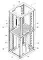
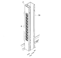
図1は、本実施例に係るラック1の外観を示した斜視説明図であり、図2は、ラック1に備えられた電源コンセント2を示した部分拡大説明図である。尚、図2では、ダクト3の側板が外されている。
ラック1は、底板21と、天板22と、底板21及び天板22の四隅同士を連結するように立設される支柱部材23、23・・と、底板21及び天板22の間に設置される仕切板24とからなる枠状体であって、天板22と仕切板24との間のスペースS1、及び仕切板24と底板21との間のスペースS2が電気機器を収納するための収納スペースとなっている。
FIG. 1 is an explanatory perspective view showing an appearance of a
The
また、各収納スペースS1、S2内の前部側縁には、一対のマウントアングル25、25が前後方向へスライド可能に取り付けられている。さらに、収納スペースS2の中央部側縁(すなわち、マウントアングル25、25の後方)で、マウントアングル25、25のスライド範囲を外れた位置には、電源ケーブル(図示せず)を収納スペースS1へ導くためのダクト3a、3bが立設されている。
各ダクトは3a、3bは、折り曲げ形成されたコ字状体に側板をネジ止めしてなる筒状体であって、内部に電源ケーブルを挿通可能となっている。また、各ダクト3a、3bは、マウントアングル25よりも左右方向で外方に設けられている(すなわち、マウントアングル25よりも左右方向で各収納スペース内方へ突出していない)。さらに、一方のダクト3aは、仕切板24よりも更に上方まで延設されており、ダクト3aの該延設部の前面には、上下方向へ複数の窓が開設された窓部4が設けられている。そして、ダクト3aの延設部内には、各窓から電源プラグの接続部を露出させるような姿勢で、電源コンセント2が取り付けられており、窓を介して電源プラグを電源コンセント2へ接続可能となっている。一方、他方のダクト3bは、仕切板24と略同一平面となる高さまでとなっている。尚、ダクト3a内を挿通された電源ケーブルは、電源コンセント2に接続されており、特に収納スペースS1内においてはダクト3a内部のみにある。
A pair of
Each of the
上記ラック1では、従来同様、マウントアングル25、25に各電気機器の取付金具等を固定することにより、電気機器を収納スペースS1、S2内へ収納するようになっている。ここで、マウントアングル25、25は、従来のように電源コンセント2に干渉したりしないため、適宜所望の位置にセットして、電気機器を取り付けることができる。そして、該ラック1に収納された電気機器は、各電源プラグをダクト3a内にある電源コンセント2へ差し込み接続して、操作・使用される。
In the
以上のような構成を有するラック1によれば、マウントアングル25の後方でその移動範囲から外れた位置にダクト3a、3bを立設するとともに、一方のダクト3aを収納スペースS1内まで延設し、該延設部内に電源コンセント2を取り付けている。したがって、従来のようにマウントアングル25と電源コンセント2とが干渉したりせず、収納する電気機器に応じてマウントアングル25を所望の位置にセットすることができ、ひいては、より奥行き寸法のある電気機器であっても収納することができる。また、マウントアングル25への電気機器の固定後に、該固定された電気機器と電源コンセント2とが干渉して、電気機器の操作、電源プラグの差し込み接続作業等が煩わしくなるといった事態も生じない。つまり、汎用性及び作業性に優れたラック1とすることができる。
According to the
さらに、電源コンセント2をダクト3a内に取り付けることで、従来の如く電源ケーブル等を収納スペースS1内で引き回す必要がなく、引き回し作業を簡略することができるし、電源ケーブル等が電気機器の収納の邪魔となったりせず、より広いスペースを収納スペースS1として確保することができる。
加えて、電源コンセント2を従来とは異なる位置に取り付けるにあたり、ダクト3aの延設部を採用しているため、ダクト3aの他に電源コンセント2を取り付けるための取付部材を別途設置したりする必要がなく、構成の合理化を図ることができる。
Furthermore, by attaching the
In addition, when the
なお、本発明のラックに係る構成は、上記実施形態に記載の態様に何ら限定されるものではなく、ダクト、電源コンセントの取付位置等に係る構成を、本発明の趣旨を逸脱しない範囲で、必要に応じて適宜変更することができる。 The configuration related to the rack of the present invention is not limited to the aspect described in the above embodiment, and the configuration related to the mounting position of the duct and the power outlet is not deviated from the gist of the present invention. It can be changed as necessary.
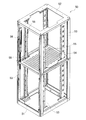
ここで、本発明に係るラックの変更例について図3をもとに説明する。図3は、本発明の変更例となるラック1’について示した斜視説明図である。尚、図3において、上記実施形態のラック1と同じ構成要素については、同じ符号を付している。
Here, a modified example of the rack according to the present invention will be described with reference to FIG. FIG. 3 is a perspective explanatory view showing a rack 1 'according to a modification of the present invention. In FIG. 3, the same components as those of the
本発明の変更例となるラック1’では、ダクト3aの延設部の前面に電源コンセント2’を露出状態で取り付けている。尚、ダクト3aの下部前面で、取付状態にある電源コンセント2’の下方隣接位置には、電源ケーブルを挿通させるための挿通孔8が開設されている。
このようなラック1’であっても、上記実施形態に記載のラック1同様、マウントアングル25と電源コンセント2’との干渉を防止することができ、ラックの汎用性を高めることができるし、電源コンセント2’への電源プラグの接続に係る作業性が損なわれたりしないといった効果がある。また、電源コンセント2’の取り付け位置の下方に隣接するように挿通孔8を開設しているため、電源ケーブルの引き回し作業の簡略化、収納スペースの有効活用といった効果も奏し得る。
In a
Even such a
さらに、上記実施形態では、収納スペースS1にのみ電源コンセントを取り付けているが、収納スペースS2に電源コンセントを取り付けても何ら問題はなく、当該取り付けに際しては、実施形態に記載の如くダクト内に取り付けたり、変更例のようにダクト前面に取り付けたりすればよい。
加えて、上記実施形態では、一方のダクトにのみ電源コンセントを取り付けているが、両方のダクトに電源コンセントを取り付けるようにしてもよいし、必要でない場合には電源コンセントが取り付けられていない側のダクトを省略することも可能である。
Further, in the above embodiment, the power outlet is attached only to the storage space S1, but there is no problem even if the power outlet is attached to the storage space S2, and the attachment is performed in the duct as described in the embodiment. Or it may be attached to the front of the duct as in the modified example.
In addition, in the above embodiment, the power outlet is attached only to one duct, but the power outlet may be attached to both ducts, and if not necessary, the power outlet is not attached. It is also possible to omit the duct.
1、1’・・ラック、2、2’・・電源コンセント、3a、3b・・ダクト、4・・窓部、25・・マウントアングル、S1、S2・・収納スペース。 1, 1 '... rack, 2, 2' ... power outlet, 3a, 3b ... duct, 4 ... window, 25 ... mount angle, S1, S2 ... storage space.
Claims (3)
前記マウントアングルの後方で移動範囲から外れた位置に、前記電源コンセントに接続された電源ケーブルを挿通可能なダクトを立設し、前記電源コンセントを該ダクトに取り付けたことを特徴とする電気機器収納用ラック。 An electrical equipment storage rack that includes a mounting angle for fixing electrical equipment in the storage space so that the mounting angle can be moved in the front-rear direction, and a power outlet to which a power plug of the electrical equipment can be connected. ,
Electrical equipment storage, characterized in that a duct through which a power cable connected to the power outlet can be inserted is erected at a position outside the moving range behind the mount angle, and the power outlet is attached to the duct. Rack.
Priority Applications (1)
| Application Number | Priority Date | Filing Date | Title |
|---|---|---|---|
| JP2007147239A JP2008300744A (en) | 2007-06-01 | 2007-06-01 | Rack for storing electric apparatus |
Applications Claiming Priority (1)
| Application Number | Priority Date | Filing Date | Title |
|---|---|---|---|
| JP2007147239A JP2008300744A (en) | 2007-06-01 | 2007-06-01 | Rack for storing electric apparatus |
Publications (1)
| Publication Number | Publication Date |
|---|---|
| JP2008300744A true JP2008300744A (en) | 2008-12-11 |
Family
ID=40173936
Family Applications (1)
| Application Number | Title | Priority Date | Filing Date |
|---|---|---|---|
| JP2007147239A Pending JP2008300744A (en) | 2007-06-01 | 2007-06-01 | Rack for storing electric apparatus |
Country Status (1)
| Country | Link |
|---|---|
| JP (1) | JP2008300744A (en) |
Cited By (2)
| Publication number | Priority date | Publication date | Assignee | Title |
|---|---|---|---|---|
| KR200452356Y1 (en) | 2009-10-05 | 2011-02-22 | 윤훈덕 | Support device for outdoor communication expenses |
| JP2012105430A (en) * | 2010-11-09 | 2012-05-31 | Nitto Kogyo Co Ltd | Electrical apparatus housing box |
-
2007
- 2007-06-01 JP JP2007147239A patent/JP2008300744A/en active Pending
Cited By (2)
| Publication number | Priority date | Publication date | Assignee | Title |
|---|---|---|---|---|
| KR200452356Y1 (en) | 2009-10-05 | 2011-02-22 | 윤훈덕 | Support device for outdoor communication expenses |
| JP2012105430A (en) * | 2010-11-09 | 2012-05-31 | Nitto Kogyo Co Ltd | Electrical apparatus housing box |
Similar Documents
| Publication | Publication Date | Title |
|---|---|---|
| JP2008176118A (en) | Optical path device | |
| JP5924028B2 (en) | Electronic device and printed circuit board connection method | |
| JP2008300744A (en) | Rack for storing electric apparatus | |
| JP6478389B2 (en) | Display support fixture | |
| KR200473723Y1 (en) | Cable duct | |
| JP2017157819A (en) | Box for information distribution board | |
| JP2009213241A (en) | Cable guide | |
| JP4899093B2 (en) | furniture | |
| JP6796451B2 (en) | Box for information distribution board | |
| JP6667944B2 (en) | Box for storing electrical and electronic equipment | |
| JP2011060988A (en) | Installation mechanism of patch panel | |
| JP2008065141A (en) | Patch panel | |
| JP2018206973A (en) | Circuit board housing enclosure and electronic device | |
| JP6598047B2 (en) | Distribution board housing and distribution board | |
| JP5621081B2 (en) | Electronic device and its rack mounting method | |
| JP2008150161A (en) | Elevator control panel | |
| JP2018074036A (en) | Information distribution board cabinet | |
| JP2006158151A (en) | Wire harness cabling structure | |
| JP7018717B2 (en) | Electronic equipment equipment | |
| JP6794036B2 (en) | Mounting unit | |
| JP6733498B2 (en) | Cable unit and server device | |
| JP6602166B2 (en) | Cable extra length unit | |
| JP6689524B2 (en) | Wiring unit | |
| JP4223914B2 (en) | Wiring box and closing member for forming the wiring box | |
| JP5903247B2 (en) | Electrical equipment storage box |