JP5863236B2 - Image processing apparatus and image processing method - Google Patents
Image processing apparatus and image processing method Download PDFInfo
- Publication number
- JP5863236B2 JP5863236B2 JP2010282400A JP2010282400A JP5863236B2 JP 5863236 B2 JP5863236 B2 JP 5863236B2 JP 2010282400 A JP2010282400 A JP 2010282400A JP 2010282400 A JP2010282400 A JP 2010282400A JP 5863236 B2 JP5863236 B2 JP 5863236B2
- Authority
- JP
- Japan
- Prior art keywords
- pixel
- pixel value
- pixels
- value
- interest
- Prior art date
- Legal status (The legal status is an assumption and is not a legal conclusion. Google has not performed a legal analysis and makes no representation as to the accuracy of the status listed.)
- Expired - Fee Related
Links
- 238000012545 processing Methods 0.000 title claims description 82
- 238000003672 processing method Methods 0.000 title claims description 6
- 238000012937 correction Methods 0.000 claims description 40
- 230000009467 reduction Effects 0.000 claims description 38
- 230000002093 peripheral effect Effects 0.000 claims description 28
- 238000004364 calculation method Methods 0.000 claims description 21
- 230000007423 decrease Effects 0.000 claims description 7
- 238000013459 approach Methods 0.000 claims description 5
- 230000002596 correlated effect Effects 0.000 claims description 4
- 238000004590 computer program Methods 0.000 claims description 3
- 230000000875 corresponding effect Effects 0.000 claims description 3
- 238000000034 method Methods 0.000 description 23
- 230000008569 process Effects 0.000 description 8
- 238000006243 chemical reaction Methods 0.000 description 6
- 238000010586 diagram Methods 0.000 description 6
- 238000009499 grossing Methods 0.000 description 6
- 238000003384 imaging method Methods 0.000 description 6
- 230000000694 effects Effects 0.000 description 5
- 230000006835 compression Effects 0.000 description 4
- 238000007906 compression Methods 0.000 description 4
- 239000004973 liquid crystal related substance Substances 0.000 description 3
- 230000002146 bilateral effect Effects 0.000 description 2
- 230000006870 function Effects 0.000 description 2
- NAWXUBYGYWOOIX-SFHVURJKSA-N (2s)-2-[[4-[2-(2,4-diaminoquinazolin-6-yl)ethyl]benzoyl]amino]-4-methylidenepentanedioic acid Chemical compound C1=CC2=NC(N)=NC(N)=C2C=C1CCC1=CC=C(C(=O)N[C@@H](CC(=C)C(O)=O)C(O)=O)C=C1 NAWXUBYGYWOOIX-SFHVURJKSA-N 0.000 description 1
- 125000002066 L-histidyl group Chemical group [H]N1C([H])=NC(C([H])([H])[C@](C(=O)[*])([H])N([H])[H])=C1[H] 0.000 description 1
- 230000009471 action Effects 0.000 description 1
- 238000011109 contamination Methods 0.000 description 1
- 238000013461 design Methods 0.000 description 1
- 230000006866 deterioration Effects 0.000 description 1
- 230000004069 differentiation Effects 0.000 description 1
- 238000001914 filtration Methods 0.000 description 1
- 230000006872 improvement Effects 0.000 description 1
- 230000003287 optical effect Effects 0.000 description 1
- 238000011946 reduction process Methods 0.000 description 1
- 238000000611 regression analysis Methods 0.000 description 1
- 230000004044 response Effects 0.000 description 1
Images


Description
本発明は、ノイズ低減技術に関するものである。 The present invention relates to a noise reduction technique.
通常、デジタルカメラ等の撮像装置により撮影された撮影画像にはノイズが含まれている。ノイズにはランダムノイズと固定パターンノイズがある。ランダムノイズは画像上の位置に関係なく現れるノイズである。固定パターンノイズは画像上の固定した位置に現れるノイズである。 Usually, a captured image captured by an imaging device such as a digital camera includes noise. There are random noise and fixed pattern noise. Random noise is noise that appears regardless of the position on the image. Fixed pattern noise is noise that appears at a fixed position on an image.
ノイズは被写体と直接関係のない画像成分であるため、被写体像にノイズが混入すると、撮影画像の画質を低下させるという問題がある。そのため、デジタルカメラなどでは信号処理回路等にてノイズ低減処理を行うことで、ノイズによる撮影画像の画質の低下を抑制している。 Since noise is an image component that is not directly related to the subject, there is a problem that if the subject image contains noise, the quality of the captured image is degraded. For this reason, in a digital camera or the like, noise reduction processing is performed by a signal processing circuit or the like, thereby suppressing deterioration in the image quality of a captured image due to noise.
従来より、様々なノイズ低減処理方法が提案されているが、それらは主として、平滑化フィルタによる処理を基礎にしている。通常、被写体像は低周波成分に比べて高周波成分の強度が弱いため、撮影画像上の高周波領域ではノイズが支配的となる。そこで高周波成分を抑圧する平滑化フィルタを撮影画像に適用すれば、被写体像の低〜中周波成分を保存しつつ、ノイズを低減しうる。このような考えに基づく平滑化フィルタはノイズ低減手法として現在広く用いられている。 Conventionally, various noise reduction processing methods have been proposed, but they are mainly based on processing by a smoothing filter. Usually, since the subject image has a weaker high-frequency component than the low-frequency component, noise is dominant in the high-frequency region on the captured image. Therefore, if a smoothing filter that suppresses high frequency components is applied to a captured image, noise can be reduced while preserving low to medium frequency components of the subject image. A smoothing filter based on this idea is now widely used as a noise reduction technique.
また、平滑化フィルタの改良としてバイラテラルフィルタと呼ばれるエッジ保存平滑化フィルタなども提案されている(非特許文献1)。しかしながら、上述したような平滑化フィルタをベースとする従来のノイズ低減技術では、被写体像の高周波成分も抑圧されてしまい、細かなテクスチャ成分が除去されてしまうことがあった。また、仮にエッジ保存特性を備えたフィルタを用いたとしても、テクスチャの振幅がある程度大きくなければ、その効果が得られない。 Further, as an improvement of the smoothing filter, an edge preserving smoothing filter called a bilateral filter has been proposed (Non-Patent Document 1). However, in the conventional noise reduction technique based on the smoothing filter as described above, the high-frequency component of the subject image is also suppressed, and a fine texture component may be removed. Even if a filter having edge preserving characteristics is used, the effect cannot be obtained unless the texture amplitude is large to some extent.
上記の課題に対し、特許文献1に記載のノイズ低減方法では、画像領域が平坦な領域であるか否かの判定を行い、平坦であると判定されれば、注目画素を領域の平均値に近づける処理を行う。特許文献1における平坦領域の判定の概要はおおよそ次のようなものである。特許文献1記載の領域判定方法は、領域の標準偏差に基づいて行い、コントラストの高いエッジ領域では標準偏差が大であるため、標準偏差が大であるときにはノイズ低減を行わない。従って、エッジ領域ではノイズ低減処理がなされず、エッジが保存される。 In response to the above problem, in the noise reduction method described in Patent Document 1, it is determined whether or not the image region is a flat region. If it is determined that the image region is flat, the target pixel is set to the average value of the region. Perform the process of approaching. The outline of the determination of the flat region in Patent Document 1 is roughly as follows. The region determination method described in Patent Document 1 is performed based on the standard deviation of the region. Since the standard deviation is large in the edge region with high contrast, noise reduction is not performed when the standard deviation is large. Therefore, noise reduction processing is not performed in the edge region, and the edge is stored.
しかし、特許文献1に記載の技術では、コントラストの低いエッジは標準偏差が小であるため、このエッジに対してはノイズ低減処理が行われてしまい、コントラストの低いエッジがぼけるという課題がある。 However, in the technique described in Patent Document 1, since an edge with low contrast has a small standard deviation, noise reduction processing is performed on this edge, and there is a problem that an edge with low contrast is blurred.
本発明は以上の問題に鑑みてなされたものであり、コントラストの低いエッジを保存しつつノイズ低減を行うための技術を提供することを目的とする。 The present invention has been made in view of the above problems, and an object thereof is to provide a technique for reducing noise while preserving edges with low contrast.
本発明の目的を達成するために、例えば、本発明の画像処理装置は以下の構成を備える。即ち、入力画像に対してノイズ低減処理を実行する画像処理装置であって、
前記入力画像中の着目画素の画素値及び該着目画素の周辺に位置するそれぞれの周辺画素の画素値を取得する取得手段と、
前記着目画素を含む領域における画素値毎の画素数に応じた画素値毎の頻度を算出する頻度計算手段と、
前記頻度計算手段によって得られる前記画素値毎の頻度に基づいて、前記着目画素の画素値における頻度および前記着目画素の画素値の近傍画素値の頻度によって決まる、前記着目画素の画素値における頻度の傾きに相関のある値を算出する傾き算出手段と、
前記傾きに相関のある値に基づく補正量を用いて、前記着目画素の画素値を補正する補正手段と
を有し、
前記補正量は、前記着目画素の画素値よりも大きい近傍画素値の画素の数が、前記着目画素の画素値よりも小さい近傍画素値の画素の数よりも多い場合には、前記着目画素の画素値を増加させる値に決定され、前記着目画素の画素値よりも小さい近傍画素値の画素の数が、前記着目画素の画素値よりも大きい近傍画素値の画素の数よりも多い場合には、前記着目画素の画素値を減少させる値に決定されることを特徴とする。
In order to achieve the object of the present invention, for example, an image processing apparatus of the present invention comprises the following arrangement. That is, an image processing apparatus that performs noise reduction processing on an input image,
Acquisition means for acquiring a pixel value of a target pixel in the input image and a pixel value of each peripheral pixel located around the target pixel;
A frequency calculating means for calculating a frequency for each pixel value according to the number of pixels for each pixel value in the region including the target pixel;
Based on the frequency for each pixel value obtained by the frequency calculation means, the frequency of the pixel value of the pixel of interest determined by the frequency of the pixel value of the pixel of interest and the frequency of neighboring pixel values of the pixel value of the pixel of interest An inclination calculating means for calculating a value correlated with the inclination;
Using the correction amount based on a value having a correlation with the inclination, have a correction means for correcting the pixel value of the target pixel,
When the number of pixels having a neighboring pixel value larger than the pixel value of the target pixel is larger than the number of pixels having a neighboring pixel value smaller than the pixel value of the target pixel, the correction amount When the pixel value is determined to be increased and the number of pixels having a neighboring pixel value smaller than the pixel value of the target pixel is larger than the number of pixels having a neighboring pixel value larger than the pixel value of the target pixel The pixel value of the pixel of interest is determined to be a value that decreases .
本発明の構成によれば、コントラストの低いエッジを保存しつつノイズ低減を行うことができる。 According to the configuration of the present invention, it is possible to reduce noise while preserving edges with low contrast.
以下、添付図面を参照し、本発明の好適な実施形態について説明する。なお、以下説明する実施形態は、本発明を具体的に実施した場合の一例を示すもので、特許請求の範囲に記載の構成の具体的な実施例の1つである。 Preferred embodiments of the present invention will be described below with reference to the accompanying drawings. The embodiment described below shows an example when the present invention is specifically implemented, and is one of the specific examples of the configurations described in the claims.
[第1の実施形態]
先ず、本実施形態に係る画像処理装置の構成例について、図1のブロック図を用いて説明する。本実施形態では、ディジタルカメラに適用した画像処理装置について説明する。
[First Embodiment]
First, a configuration example of the image processing apparatus according to the present embodiment will be described with reference to the block diagram of FIG. In the present embodiment, an image processing apparatus applied to a digital camera will be described.
撮像部101は、外界の光をその光量に応じた映像信号として取得するものである。撮像部101は、例えば、ズームレンズ、フォーカスレンズ、ぶれ補正レンズ、絞り、シャッター、光学ローパスフィルタ、iRカットフィルタ、カラーフィルタ、CMOSやCCDなどのセンサ、等により構成されている。A/D変換部102は、撮像部101から送出された映像信号(アナログ信号)をディジタル信号(データ)に変換する。
The
信号処理部103は、A/D変換部102により得られたデータが表す入力画像に対してホワイトバランス処理、ガンマ補正処理、ノイズ低減処理等の信号処理を行う。エンコーダ部105は、信号処理部103による信号処理済みの入力画像に対してJpegやMpegなどの圧縮符号化処理を行い、符号化画像データを生成する。もちろん、この圧縮符号化方法には様々なものがあり、特定の方法に限定するものではないし、そもそもこの圧縮符号化は必須ではない。
The
メディアI/F106には、PC(パーソナルコンピュータ)やその他メディア(例えば、ハードディスク、メモリーカード、CFカード、SDカード、USBメモリ)を接続することができる。然るに、エンコーダ部105による符号化画像データ(若しくは非圧縮符号化画像データ)は、このメディアI/F106を介してPCやその他のメディアに対して記録することができる。
A PC (personal computer) and other media (for example, hard disk, memory card, CF card, SD card, USB memory) can be connected to the media I / F 106. However, the encoded image data (or uncompressed encoded image data) by the
D/A変換部104は、信号処理部103による信号処理済みの入力画像(ディジタル信号)をアナログ信号に変換する。表示部113は液晶画面などにより構成されており、このアナログ信号が表す入力画像を表示する。また、この表示部113には、キャラクタジェネレーション部112により生成された文字やグラフィックなども表示することができる。
The D /
CPU107は、ROM108やRAM109に格納されているコンピュータプログラムやデータを用いて画像処理装置全体の動作制御を行う。ROM108には、画像処理装置を構成する各部の動作制御をCPU107に実行させるためのコンピュータプログラムやデータが格納されている。また、既知の情報(予め設定された情報)として後述する様々なものもこのROM108に格納されている。
The
RAM109は、様々なデータを一時的に記憶するためのエリアや、CPU107が各種の処理を実行する際に用いるワークエリアを有する。即ち、RAM109は、各種のエリアを適宜提供することができる。
The
撮像系制御部110は、上記の撮像部101の制御を行うものであり、フォーカスを合わせる、シャッターを開く、絞りを調節するなどの、CPU107から指示された様々な制御を行う。
The imaging system control unit 110 controls the
操作部111は、ボタンやモードダイヤル等のユーザインターフェースにより構成されており、ユーザはこの操作部111を操作することで、各種の指示をCPU107に対して入力することができる。なお、上記の表示部113がタッチパネル式の液晶画面で構成されている場合、ユーザは周知の如く、このタッチパネル式の液晶画面を自身の指などでタッチすることで、CPU107に対して様々な指示入力を行うことができる。
The
なお、図1には、以下の説明で用いる構成用件を含む一部の構成のみについて示している。然るに、本実施形態に係る画像処理装置に適用可能な構成は、図1に示した構成に限るものではなく、図1に示した構成に適当な構成用件を加えたものであっても良いし、以下の処理が実現可能であれば、適当な構成用件を省いても良い。また、1つの構成用件が行うものとして後述する処理を他の構成用件に行わせても良いし、それぞれで分配しても良い。 FIG. 1 shows only a part of the configuration including the configuration requirements used in the following description. However, the configuration applicable to the image processing apparatus according to the present embodiment is not limited to the configuration illustrated in FIG. 1, and may be a configuration in which appropriate configuration requirements are added to the configuration illustrated in FIG. However, if the following processing can be realized, an appropriate configuration requirement may be omitted. Further, the processing described later as one configuration requirement may be performed by another configuration requirement, or may be distributed by each.
次に、信号処理部103のより詳細な構成について、図2のブロック図を用いて説明する。信号処理部103は、A/D変換部102から送出された入力画像の画質を向上させるためのもので、先ずはこの入力画像に対してノイズ低減処理部201によってノイズ低減処理が施される。そしてノイズ低減処理部201によりノイズ低減処理が施された入力画像に対して、ホワイトバランス制御部によるホワイトバランス処理、エッジ強調部によるエッジ強調処理、色変換部による色変換処理、ガンマ処理部によるγ補正処理、が順に施される。そしてガンマ処理部からは、以上の各処理が施された入力画像が出力される。なお、画質を向上させるためには、ノイズ低減処理部201による処理だけでも良いし、ノイズ低減処理部201による処理と、ホワイトバランス制御部、エッジ強調部、色変換部、ガンマ処理部の1以上による処理と、で実現させても良い。
Next, a more detailed configuration of the
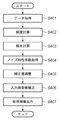
次に、ノイズ低減処理部201のより詳細な構成について、図3のブロック図、及び図4のフローチャートを用いて説明する。先ず、ステップS401において頻度計算部301は、A/D変換部102から送出された入力画像を取得する。
Next, a more detailed configuration of the noise
ステップS402では頻度計算部301は先ず、入力画像中の着目画素及び着目画素の周辺に位置する周辺画素、のそれぞれの画素の画素値を取得する。例えば、着目画素、着目画素の周囲に位置する8画素、のそれぞれの画素の画素値を取得する。
In step S <b> 402, the
そして次に頻度計算部301は、着目画素の周辺に位置する周辺画素のそれぞれの画素値から、着目画素の画素値xと同じ画素値を有する画素の数を求める。更に頻度計算部301は、着目画素の周辺に位置する周辺画素のそれぞれの画素値から、着目画素の画素値xより小さい画素値のうち着目画素の画素値xに最も近い画素値を有する画素の数H1を求める。更に頻度計算部301は、着目画素の周辺に位置する周辺画素のそれぞれの画素値から、着目画素の画素値xより大きい画素値のうち着目画素の画素値xに最も近い画素値を有する画素の数H2を求める。
Then, the
例えば、着目画素の画素値がP3、着目画素の周辺に位置する8画素のそれぞれの画素値がP2、P4、P2、P1、P5、P4、P3、P2であったとする。ここで、P1<P2<P3<P4<P5であるとする。このとき、画素値P1を有する画素の数は1、画素値P2を有する画素の数は3、画素値P3を有する画素の数は2、画素値P4を有する画素の数は2、画素値P5を有する画素の数は1、となる。然るにこの場合、ステップS402では頻度計算部301は、着目画素の画素値x(=P3)と同じ画素値を有する周辺画素の数として「1」を求める。更に、着目画素の画素値xより小さい画素値のうち着目画素の画素値xに最も近い画素値(=P2)を有する周辺画素の数として「3」を求める。更に、着目画素の画素値xより大きい画素値のうち着目画素の画素値xに最も近い画素値(=P4)を有する周辺画素の数「2」を求める。
For example, assume that the pixel value of the pixel of interest is P3, and the pixel values of the eight pixels located around the pixel of interest are P2, P4, P2, P1, P5, P4, P3, and P2. Here, it is assumed that P1 <P2 <P3 <P4 <P5. At this time, the number of pixels having the pixel value P1 is 1, the number of pixels having the pixel value P2 is 3, the number of pixels having the pixel value P3 is 2, the number of pixels having the pixel value P4 is 2, and the pixel value P5 The number of pixels having 1 is 1. In this case, however, in step S402, the
なお、入力画像中の着目画素の周辺に位置する周辺画素を用いて各画素値に対する画素数を計算するものとしても良いが、全ての画素を用いなくても良く、着目画素の画素値に近い画素値を有する周辺画素数が得られればよい。例えば、着目画素の画素値が「100」である場合、画素値が「80」〜「120」の範囲内の画素の数を得るようにしても良い。 Note that the number of pixels for each pixel value may be calculated using peripheral pixels located around the pixel of interest in the input image, but not all pixels may be used and is close to the pixel value of the pixel of interest. It is only necessary to obtain the number of peripheral pixels having a pixel value. For example, when the pixel value of the target pixel is “100”, the number of pixels within the range of the pixel value “80” to “120” may be obtained.
ステップS403では、傾き計算部302は、以下の式を計算することで、着目画素を含む近傍領域内で、同じ画素値を有する画素数の増減(=傾きa)を求める。然るに、この増減を求めることができるのであれば、他の式を用いても構わない。
In step S <b> 403, the

ここで、H(x)は、着目画素の画素値がxである場合に、着目画素の周辺に位置する周辺画素のうち、画素値xを有する画素の数を示す。H(x−1)は上記のH1に対応し、H(x+1)は上記のH2に対応している。 Here, H (x) indicates the number of pixels having the pixel value x among the peripheral pixels located around the target pixel when the pixel value of the target pixel is x. H (x−1) corresponds to the above H1, and H (x + 1) corresponds to the above H2.
ステップS404では補正量調整部303は、ROM108等に格納されているノイズ特性係数を取得する。本実施形態では、このノイズ特性係数として、C1,C2を取得する。この係数C1,C2は以下の式を満たす。
In step S404, the correction
![]()
![]()
この式においてIは、着目画素の画素値としても良いし、着目画素の画素値及び着目画素の周辺に位置する周辺画素の画素値の平均画素値、としても良い。ノイズ特性係数は、撮影画像に含まれるノイズの大きさを示している。具体的にはチャートを撮影した画像から算出したノイズの分散などである。なおショットノイズは輝度に応じてノイズ量が増加することが知られている。そこで、撮影画像に含まれるノイズの分散σ2と画素値Iの関係を係数C1,C2を用いて上記の式(2)のように表して係数C1,C2をノイズ特性係数とすることが好適である。 In this equation, I may be the pixel value of the pixel of interest, or may be the average pixel value of the pixel value of the pixel of interest and the pixel values of peripheral pixels located around the pixel of interest. The noise characteristic coefficient indicates the magnitude of noise included in the captured image. Specifically, noise variance calculated from an image obtained by photographing a chart. It is known that the amount of noise of shot noise increases according to the luminance. Therefore, it is preferable that the relationship between the variance σ 2 of the noise included in the photographed image and the pixel value I is expressed as the above equation (2) using the coefficients C1 and C2 and the coefficients C1 and C2 are the noise characteristic coefficients. It is.
然るにC1は主としてショットノイズに関わる項、C2は主として暗電流ノイズに関わる項となる。C1,C2はグレイスケールチャートを撮影した画像から求める。具体的には、グレースケールチャートにおいて反射率一定の領域に対応する撮影画像の領域の平均値と分散値の関係を式(2)により回帰分析してC1,C2を求める。撮影画像から求める方法の他にも、設計パラメータから、撮影画像に含まれるであろうノイズの分散を算出しても良い。 However, C1 is a term mainly related to shot noise, and C2 is a term mainly related to dark current noise. C1 and C2 are obtained from the image of the gray scale chart. Specifically, C1 and C2 are obtained by performing regression analysis on the relationship between the average value and the variance value of the region of the captured image corresponding to the region having a constant reflectance in the gray scale chart using the equation (2). In addition to the method of obtaining from a captured image, the variance of noise that will be included in the captured image may be calculated from design parameters.
いずれにせよ、ショットノイズ量は輝度に依存するため、着目画素あるいは周辺画素の画素値に応じてノイズ量σ2を計算することが望ましい。なお、着目画素の画素値が大きい場合、式(2)により着目画素に含まれるであろうノイズ量σ2が増大する。以下に説明する補正量はノイズ量σ2に比例するため、着目画素の補正量は大きくなる事が分かる。なお、傾きaが正である場合とは、着目画素に対して、着目画素の画素値よりも値が大きい画素の数が着目画素よりも値が小さい画素の数に対して多いことを意味する。その場合には、補正は着目画素の画素値を増加させる作用があることが式(1)から分かる。逆も然りである。 In any case, since the shot noise amount depends on the luminance, it is desirable to calculate the noise amount σ 2 according to the pixel value of the pixel of interest or the surrounding pixels. Note that when the pixel value of the target pixel is large, the amount of noise σ 2 that will be included in the target pixel increases according to Equation (2). Since the correction amount described below is proportional to the noise amount σ 2, it can be seen that the correction amount of the pixel of interest increases. Note that the case where the slope a is positive means that the number of pixels having a larger value than the pixel value of the target pixel is larger than the number of pixels having a smaller value than the target pixel. . In that case, it can be seen from Equation (1) that the correction has the effect of increasing the pixel value of the pixel of interest. The reverse is also true.
ステップS405では補正量調整部303は、ステップS404で取得したC1,C2、着目画素の画素値(若しくは着目画素の画素値及び着目画素の周辺に位置する周辺画素の画素値の平均画素値)I、を用いて上記の式(2)を計算し、σ2を求める。次に補正量調整部303は、求めたσ2と上記の式(1)で計算した傾きaとを用いてσ2×aを、補正量として計算し、加算器304に送出する。
In step S405, the correction
ステップS406では加算器304は、着目画素の画素値xに対して補正量(σ2×a)を加算した結果(x+σ2×a)を、着目画素の新たな画素値として、ホワイトバランス制御部に対して出力する。 In step S406, the adder 304 uses the result (x + σ 2 × a) obtained by adding the correction amount (σ 2 × a) to the pixel value x of the pixel of interest as a new pixel value of the pixel of interest, and the white balance control unit Output for.
図4のフローチャートは、1つの画素(=着目画素)に対する処理のフローチャートであるため、ノイズ低減処理部201は、図4のフローチャートに従った処理を、入力画像を構成する各画素について行うことになる。図4のフローチャートに従った処理を、入力画像を構成する各画素について行うことで得られる画像は、ノイズ低減後の画像となる。
Since the flowchart of FIG. 4 is a flowchart of the process for one pixel (= target pixel), the noise
なお、画像の境界付近では着目画素の周辺画素が存在しない場合がある。その際は、仮想的に所定画素値の画素が周辺画素として存在するとして計算したり、領域内には画素が存在するよう領域の形状を変更するなどが考えられる。 Note that there may be no surrounding pixels of the pixel of interest near the boundary of the image. In that case, it can be considered that a pixel having a predetermined pixel value virtually exists as a peripheral pixel, or the shape of the region is changed so that the pixel exists in the region.
次に、入力画像を構成する各画素について図4のフローチャートに従った処理を行うことで得られる画像については、コントラストの低いエッジが暈けないことについて説明する。 Next, it will be described that an edge having a low contrast cannot be produced in an image obtained by performing processing according to the flowchart of FIG. 4 for each pixel constituting the input image.
先ず、本実施形態に係る上記の処理によりノイズが良好に低減できる理由について説明する。入力画像中の着目画素の画素値をx、周辺画素のうち画素値xを有する画素数をH(x)、H(x)をxについて微分した結果をH’(x)、入力画像に混入しているノイズの標準偏差をσとする。このとき、ノイズ低減処理部201により着目画素の画素値xは以下の式(3)に従って画素値x’に更新されることになる。
First, the reason why noise can be satisfactorily reduced by the above processing according to the present embodiment will be described. The pixel value of the pixel of interest in the input image is x, the number of pixels having the pixel value x among the peripheral pixels is H (x), the result of differentiation of H (x) with respect to x is H ′ (x), and mixed in the input image Let σ be the standard deviation of the noise. At this time, the pixel value x of the target pixel is updated to the pixel value x ′ by the noise
この式(3)により、なぜノイズ低減が良好に行われるのかを説明する。ノイズ混入前の画像が一様な画素値x0を有しており、この画像に対して標準偏差σのノイズが混入すると、混入後の画像のヒストグラムは以下の式(4)の正規分布で表すことができる。 The reason why noise reduction is performed satisfactorily will be described using this equation (3). If the image before noise mixing has a uniform pixel value x 0 and noise of standard deviation σ is mixed into this image, the histogram of the image after mixing is a normal distribution of the following equation (4). Can be represented.
上記の式(3)と式(4)から、ノイズ低減後の画素値x'は以下の式(5)に示すとおり、ノイズ混入前の画素値x0がノイズ低減後の画素値x’となることが分かる。 From the above equation (3) and (4), the pixel value x after the noise reduction 'is as shown in the following equation (5), the pixel value x 0 before noise contamination pixel value x after the noise reduction' and I understand that
![]()
![]()
ただし、式(4)で表される正規分布はなめらかな関数であることに注意が必要である。仮に着目画素の周辺領域が小さすぎる場合、少ないサンプルからヒストグラムH(x)を計算することになり、式(4)のようななめらかな理想的なヒストグラムは得られないし、式(3)の計算結果が(式(5))となる保証は無い。 However, it should be noted that the normal distribution represented by Equation (4) is a smooth function. If the peripheral area of the pixel of interest is too small, the histogram H (x) is calculated from a small number of samples, and a smooth ideal histogram such as the equation (4) cannot be obtained, and the equation (3) is calculated. There is no guarantee that the result will be (Expression (5)).
正規分布に従う乱数を計算機で発生させて、そのヒストグラムを表したものを図5に示す。図5において実線がヒストグラムであり、波線が正規分布(理想的なヒストグラム)である。サンプル数が有限であるため、ヒストグラムは滑らかではなく正規分布に一致しない。このような事態を避けるため、ヒストグラムをとる画像領域を広くするか、サンプル数が少なくても良好な結果を得る工夫が必要である。例えば、式(1)は離散データから傾きを示す量を得る一般的な数式であるが、サンプル数が少ない場合にはヒストグラムは滑らかでないため、aは理想値より大きな値をとる可能性がある。そこで、以下の式(6)に示すように、サンプル数Nを用いて修正する工夫が考えられる。 FIG. 5 shows a histogram in which random numbers according to the normal distribution are generated by a computer. In FIG. 5, the solid line is a histogram, and the wavy line is a normal distribution (ideal histogram). Due to the finite number of samples, the histogram is not smooth and does not match the normal distribution. In order to avoid such a situation, it is necessary to devise a method for obtaining a good result even if the image area for taking the histogram is widened or the number of samples is small. For example, Equation (1) is a general equation for obtaining an amount indicating a slope from discrete data. However, since the histogram is not smooth when the number of samples is small, a may take a value larger than the ideal value. . Therefore, as shown in the following equation (6), a device for correcting using the number of samples N can be considered.
式(6)によれば、サンプル数が少ないときには分母が大きくなり、傾きを示す量aは小さくなる。つまり、式(6)は傾きを示す量aが過度に大きくなる事を防ぐ効果があり、良好な結果を得る事ができる。なお、式(6)のサンプル数Nはx-1,x,x+1の度数の総和である。 According to Equation (6), when the number of samples is small, the denominator is large, and the amount a indicating the inclination is small. That is, the formula (6) has an effect of preventing the amount “a” indicating the slope from becoming excessively large, and a good result can be obtained. Note that the number of samples N in Equation (6) is the sum of the frequencies of x-1, x, and x + 1.
次に、ノイズ混入前の画像が一様では無い場合を考える。ノイズ混入前の画像のヒストグラムをh(α)とする。するとノイズ混入後の画像のヒストグラムはh(α)を用いて以下の式(7)のように表すことができる。 Next, consider a case where the image before noise mixing is not uniform. Let h (α) be the histogram of the image before noise mixing. Then, the histogram of the image after mixing noise can be expressed as in the following formula (7) using h (α).
式(7)は、撮影画像のヒストグラムについて新しい見方を提供している。総和記号の中身はノイズ混入前に画素値がαであり、なおかつノイズ混入により画素値xに変化した画素の数に等しい。式(7)全体を見ると、入力画像の画素値xの度数は、ノイズ混入により画素値xに変化するようなノイズ混入前の画素値αの総和に等しい。式(7)を式(3)に代入すると以下の式(8)が得られる。 Equation (7) provides a new view of the histogram of the captured image. The content of the sum symbol is equal to the number of pixels whose pixel value is α before noise is mixed and which has changed to the pixel value x due to noise. Looking at Expression (7) as a whole, the frequency of the pixel value x of the input image is equal to the sum of the pixel values α before noise mixing that changes to the pixel value x due to noise mixing. Substituting equation (7) into equation (3) yields the following equation (8).
式(8)の一部である次式(9)の意味を考える。 Consider the meaning of equation (9), which is part of equation (8).
式(9)が表す量は、ノイズ混入により画素値がαからxに変化した画素の数を、ノイズ混入後の画素xの数で割っている。すなわち式(9)が表す量は、撮影画像の画素値がxである画素のうち、何%がノイズ混入前は画素値αであったのかを示す量である。これはノイズがのった画素値xを取得したうえで、ノイズ混入前は画素値αである事後確率P(α|x)に等しい。式(9)が表す量をP(α|x)とおくと式(8)は以下の式(10)に示す如く変形できる。 The amount represented by Equation (9) is obtained by dividing the number of pixels whose pixel value has changed from α to x due to noise mixing by the number of pixels x after noise mixing. That is, the amount represented by Expression (9) is an amount indicating what percentage of the pixels having the pixel value x of the captured image that were the pixel value α before the noise was mixed. This is equal to the posterior probability P (α | x) of the pixel value α before the noise is mixed after obtaining the pixel value x with noise. If the amount represented by equation (9) is P (α | x), equation (8) can be modified as shown in equation (10) below.
![]()
![]()
式(10)を展開すると、以下の式(11)が得られる。 When formula (10) is expanded, the following formula (11) is obtained.
ここで、ΣP(α|x)=1(式(11)の右辺の最後の項)であるから、最終的に式(11)は以下の式(12)に変形することができる。 Here, since ΣP (α | x) = 1 (the last term on the right side of Expression (11)), Expression (11) can be finally transformed into Expression (12) below.
式(12)は画素値xを取得したという条件付きで、ノイズ混入前は画素値がαである確率を用いてノイズ混入前の画素値の期待値を計算している。つまり、式(3)を用いてノイズ低減後の画素値を得ることは、実質的にノイズ混入前の画素値の期待値を求めていることになる。以上が式(3)によりノイズ低減が行える理由である。特筆すべきは、式(3)はノイズ混入前のヒストグラムを直接求めることなしに、期待値演算によりノイズ混入前の画素値の期待値を計算できることである。 Expression (12) is conditional on the acquisition of the pixel value x, and the expected value of the pixel value before noise mixing is calculated using the probability that the pixel value is α before noise mixing. In other words, obtaining the pixel value after noise reduction using Equation (3) substantially determines the expected value of the pixel value before noise mixing. The above is the reason why the noise can be reduced by the equation (3). It should be noted that the expression (3) can calculate the expected value of the pixel value before noise mixing by the expected value calculation without directly obtaining the histogram before noise mixing.
次に、本実施形態に係る上記の処理により低コントラストのエッジが保存できる理由について説明する。本実施形態に係る上記の処理によるノイズ低減方法の作用を図6に示す。図6には、撮影画像のヒストグラムと、画素値の補正方向の関係を表している。 Next, the reason why low-contrast edges can be preserved by the above processing according to the present embodiment will be described. The operation of the noise reduction method by the above processing according to the present embodiment is shown in FIG. FIG. 6 shows the relationship between the histogram of the captured image and the correction direction of the pixel value.
図6において平均値よりも値が小さい画素値は勾配が正となり、ヒストグラムのピークに近づくよう補正がなされる。一方、平均値よりも値が大きい画素値は勾配が負となり、補正結果としては着目画素の画素値は減少し、やはりヒストグラムのピークに近づくよう補正される。ノイズ混入によりヒストグラムは広がるため、本実施形態に係る上記の処理によるノイズ低減方法は、広がった画素値をノイズ混入前の状態に近づける作用があることが分かる。 In FIG. 6, the pixel value having a value smaller than the average value has a positive gradient, and correction is performed so as to approach the peak of the histogram. On the other hand, the pixel value having a value larger than the average value has a negative gradient, and as a correction result, the pixel value of the pixel of interest decreases and is corrected so as to approach the peak of the histogram. Since the histogram spreads due to noise mixing, it can be seen that the noise reduction method by the above processing according to the present embodiment has an effect of bringing the spread pixel value closer to the state before noise mixing.
入力画像が低コントラストのエッジを含む場合のヒストグラムと画素値の補正方向の関係とを図7(a)に示す。図7(a)の画素値a,bはエッジを構成する画素値の、それぞれの平均値である。ノイズ混入前の状態では図7(b)に示すヒストグラムのように画素値a,bでのみ0でない度数を有する。図7(a)の画素値の補正方向を見ると、ピークa,b以外の入力画像の画素値はピークa,bに近づくように補正がなされる。ノイズ混入前の画素値であるa,bと等しい画素値を有する画素は傾きが0であるため補正がなされない。そのため、補正の効果としてはエッジのコントラストの低下を押さえて、ノイズ混入前の状態に近づける作用がある。 FIG. 7A shows the relationship between the histogram and the correction direction of the pixel value when the input image includes a low contrast edge. The pixel values a and b in FIG. 7A are average values of the pixel values constituting the edge. In the state before mixing noise, the pixel values a and b have non-zero frequencies as in the histogram shown in FIG. When viewing the correction direction of the pixel values in FIG. 7A, the pixel values of the input image other than the peaks a and b are corrected so as to approach the peaks a and b. A pixel having a pixel value equal to a and b which is a pixel value before noise is mixed is not corrected because the inclination is zero. Therefore, as an effect of the correction, there is an action of suppressing a decrease in edge contrast and bringing it closer to a state before noise mixing.
以上のことは、ヒストグラムのピークに位置する画素値a,bが近い値をとっていたとしても成り立つ。従って、本実施形態に係る上記の処理によるノイズ低減方法では、コントラストの低いエッジでもコントラストを維持しつつ、ノイズ低減がなされる。 The above is true even if the pixel values a and b located at the peak of the histogram take close values. Therefore, in the noise reduction method by the above processing according to the present embodiment, noise is reduced while maintaining contrast even at an edge with low contrast.
[第2の実施形態]
第1の実施形態では、ノイズ低減処理部201をディジタルカメラに搭載した場合について説明したが、第1の実施形態で説明したノイズ低減処理部201の動作は、ノイズ低減処理が必要な様々な画像処理装置に組み込むことが可能である。
[Second Embodiment]
In the first embodiment, the case where the noise
また、ノイズ低減処理部201はハードウェアで構成しても良いが、ソフトウェアで実装し、ROMなどに格納しても良い。この場合、このROM及びCPUを有する機器において、CPUがこのROMに格納されたこのソフトウェアを実行することにより、この機器は第1の実施形態でノイズ低減処理部201が行うものとして上述した各処理を実行することになる。
The noise
(その他の実施例)
また、本発明は、以下の処理を実行することによっても実現される。即ち、上述した実施形態の機能を実現するソフトウェア(プログラム)を、ネットワーク又は各種記憶媒体を介してシステム或いは装置に供給し、そのシステム或いは装置のコンピュータ(またはCPUやMPU等)がプログラムを読み出して実行する処理である。
(Other examples)
The present invention can also be realized by executing the following processing. That is, software (program) that realizes the functions of the above-described embodiments is supplied to a system or apparatus via a network or various storage media, and a computer (or CPU, MPU, or the like) of the system or apparatus reads the program. It is a process to be executed.
Claims (7)
前記入力画像中の着目画素の画素値及び該着目画素の周辺に位置するそれぞれの周辺画素の画素値を取得する取得手段と、
前記着目画素を含む領域における画素値毎の画素数に応じた画素値毎の頻度を算出する頻度計算手段と、
前記頻度計算手段によって得られる前記画素値毎の頻度に基づいて、前記着目画素の画素値における頻度および前記着目画素の画素値の近傍画素値の頻度によって決まる、前記着目画素の画素値における頻度の傾きに相関のある値を算出する傾き算出手段と、
前記傾きに相関のある値に基づく補正量を用いて、前記着目画素の画素値を補正する補正手段と
を有し、
前記補正量は、前記着目画素の画素値よりも大きい近傍画素値の画素の数が、前記着目画素の画素値よりも小さい近傍画素値の画素の数よりも多い場合には、前記着目画素の画素値を増加させる値に決定され、前記着目画素の画素値よりも小さい近傍画素値の画素の数が、前記着目画素の画素値よりも大きい近傍画素値の画素の数よりも多い場合には、前記着目画素の画素値を減少させる値に決定されることを特徴とする画像処理装置。 An image processing apparatus that performs noise reduction processing on an input image,
Acquisition means for acquiring a pixel value of a target pixel in the input image and a pixel value of each peripheral pixel located around the target pixel;
A frequency calculating means for calculating a frequency for each pixel value according to the number of pixels for each pixel value in the region including the target pixel;
Based on the frequency for each pixel value obtained by the frequency calculation means, the frequency of the pixel value of the pixel of interest determined by the frequency of the pixel value of the pixel of interest and the frequency of neighboring pixel values of the pixel value of the pixel of interest An inclination calculating means for calculating a value correlated with the inclination;
Using the correction amount based on a value having a correlation with the inclination, have a correction means for correcting the pixel value of the target pixel,
When the number of pixels having a neighboring pixel value larger than the pixel value of the target pixel is larger than the number of pixels having a neighboring pixel value smaller than the pixel value of the target pixel, the correction amount When the pixel value is determined to be increased and the number of pixels having a neighboring pixel value smaller than the pixel value of the target pixel is larger than the number of pixels having a neighboring pixel value larger than the pixel value of the target pixel The image processing apparatus is determined to have a value that decreases the pixel value of the pixel of interest .
前記入力画像中の着目画素の画素値及び該着目画素の周辺に位置するそれぞれの周辺画素の画素値を取得する取得手段と、
前記それぞれの周辺画素の画素値のうち最多画素数となる画素値に近づくように、前記着目画素の画素値を補正する補正手段と
を有し、
前記補正手段は、
前記それぞれの周辺画素の画素値を用いて、該それぞれの周辺画素のうち該画素値を有する画素数を算出する頻度計算手段と、
前記頻度計算手段により算出された結果に応じて、前記着目画素の画素値に対する補正量を決定する決定手段と、
前記補正量を用いて、前記着目画素の画素値を更新する更新手段と
を有し、
前記頻度計算手段は、
前記着目画素の画素値xと同じ画素値を有する画素の数をHとし、
前記それぞれの周辺画素の画素値から、前記画素値xより小さい画素値のうち該画素値xに最も近い画素値を有する画素の数H1を計算すると共に、前記それぞれの周辺画素の画素値から、前記画素値xより大きい画素値のうち該画素値xに最も近い画素値を有する画素の数H2を計算し、
前記決定手段は、
a=(H2−H1)/(2×H)を計算すると共に、前記画素値x、若しくは前記着目画素及び前記それぞれの周辺画素の画素値の平均画素値、をIとした場合に、予め設定された係数C1,C2を用いて、σ2=C1×I+C2を計算し、a×σ2を補正量として決定する
ことを特徴とする画像処理装置。 An image processing apparatus that performs noise reduction processing on an input image,
Acquisition means for acquiring a pixel value of a target pixel in the input image and a pixel value of each peripheral pixel located around the target pixel;
Correction means for correcting the pixel value of the pixel of interest so as to approach the pixel value that is the largest number of pixels among the pixel values of the respective surrounding pixels,
The correction means includes
Frequency calculation means for calculating the number of pixels having the pixel value among the respective peripheral pixels, using the pixel values of the respective peripheral pixels;
Determining means for determining a correction amount for the pixel value of the target pixel according to the result calculated by the frequency calculating means;
Updating means for updating the pixel value of the pixel of interest using the correction amount;
The frequency calculation means includes
Let H be the number of pixels having the same pixel value as the pixel value x of the pixel of interest,
From the pixel values of the respective peripheral pixels, the number H1 of pixels having the pixel value closest to the pixel value x among the pixel values smaller than the pixel value x is calculated, and from the pixel values of the respective peripheral pixels, Calculating the number H2 of pixels having a pixel value closest to the pixel value x among the pixel values greater than the pixel value x;
The determining means includes
When a = (H2−H1) / (2 × H) is calculated and I is the pixel value x or the average pixel value of the pixel of interest and each of the surrounding pixels, it is set in advance. An image processing apparatus, wherein σ2 = C1 × I + C2 is calculated using the obtained coefficients C1 and C2, and a × σ2 is determined as a correction amount.
前記傾き算出手段は、前記H(x)をxについて微分した結果を前記傾きに相関のある値として算出することを特徴とする請求項1又は2に記載の画像処理装置。 When the pixel value of the pixel of interest is x and the number of pixels having the pixel value x calculated by the frequency calculation means is H (x),
The inclination calculation means, an image processing apparatus according to claim 1 or 2, characterized in that to calculate the result of said H (x) is differentiated with respect to x as a value correlated to the inclination.
前記画像処理装置の取得手段が、前記入力画像中の着目画素の画素値及び該着目画素の周辺に位置するそれぞれの周辺画素の画素値を取得する取得工程と、
前記画像処理装置の頻度計算手段が、前記着目画素を含む領域における画素値毎の画素数に応じた画素値毎の頻度を算出する頻度計算工程と、
前記画像処理装置の傾き算出手段が、前記頻度計算工程によって得られる前記画素値毎の頻度に基づいて、前記着目画素の画素値における頻度および前記着目画素の画素値の近傍画素値の頻度によって決まる、前記着目画素の画素値における頻度の傾きに相関のある値を算出する傾き算出工程と、
前記画像処理装置の補正手段が、前記傾きに相関のある値に基づく補正量を用いて、前記着目画素の画素値を補正する補正工程と
を有し、
前記補正量は、前記着目画素の画素値よりも大きい近傍画素値の画素の数が、前記着目画素の画素値よりも小さい近傍画素値の画素の数よりも多い場合には、前記着目画素の画素値を増加させる値に決定され、前記着目画素の画素値よりも小さい近傍画素値の画素の数が、前記着目画素の画素値よりも大きい近傍画素値の画素の数よりも多い場合には、前記着目画素の画素値を減少させる値に決定されることを特徴とする画像処理方法。 An image processing method performed by an image processing apparatus that performs noise reduction processing on an input image,
An acquisition step in which the acquisition unit of the image processing apparatus acquires a pixel value of a pixel of interest in the input image and a pixel value of each peripheral pixel located around the pixel of interest;
A frequency calculation step in which the frequency calculation means of the image processing device calculates a frequency for each pixel value according to the number of pixels for each pixel value in the region including the target pixel;
The inclination calculation means of the image processing device is determined by the frequency of the pixel value of the pixel of interest and the frequency of neighboring pixel values of the pixel value of the pixel of interest based on the frequency for each pixel value obtained by the frequency calculation step. An inclination calculating step of calculating a value correlated with the inclination of the frequency of the pixel value of the target pixel;
Correction means of the image processing apparatus, by using the correction amount based on a value having a correlation with the inclination, have a correction step of correcting the pixel value of the target pixel,
When the number of pixels having a neighboring pixel value larger than the pixel value of the target pixel is larger than the number of pixels having a neighboring pixel value smaller than the pixel value of the target pixel, the correction amount When the pixel value is determined to be increased and the number of pixels having a neighboring pixel value smaller than the pixel value of the target pixel is larger than the number of pixels having a neighboring pixel value larger than the pixel value of the target pixel The image processing method is characterized in that it is determined to be a value that decreases the pixel value of the pixel of interest .
前記画像処理装置の取得手段が、前記入力画像中の着目画素の画素値及び該着目画素の周辺に位置するそれぞれの周辺画素の画素値を取得する取得工程と、
前記画像処理装置の補正手段が、前記それぞれの周辺画素の画素値のうち最多画素数となる画素値に近づくように、前記着目画素の画素値を補正する補正工程と
を有し、
前記補正工程は、
前記それぞれの周辺画素の画素値を用いて、該それぞれの周辺画素のうち該画素値を有する画素数を算出する頻度計算工程と、
前記頻度計算工程で算出された結果に応じて、前記着目画素の画素値に対する補正量を決定する決定工程と、
前記補正量を用いて、前記着目画素の画素値を更新する更新工程と
を有し、
前記頻度計算工程では、
前記着目画素の画素値xと同じ画素値を有する画素の数をHとし、
前記それぞれの周辺画素の画素値から、前記画素値xより小さい画素値のうち該画素値xに最も近い画素値を有する画素の数H1を計算すると共に、前記それぞれの周辺画素の画素値から、前記画素値xより大きい画素値のうち該画素値xに最も近い画素値を有する画素の数H2を計算し、
前記決定工程では、
a=(H2−H1)/(2×H)を計算すると共に、前記画素値x、若しくは前記着目画素及び前記それぞれの周辺画素の画素値の平均画素値、をIとした場合に、予め設定された係数C1,C2を用いて、σ2=C1×I+C2を計算し、a×σ2を補正量として決定する
ことを特徴とする画像処理方法。 An image processing method performed by an image processing apparatus that performs noise reduction processing on an input image,
An acquisition step in which the acquisition unit of the image processing apparatus acquires a pixel value of a pixel of interest in the input image and a pixel value of each peripheral pixel located around the pixel of interest;
A correction step of correcting the pixel value of the pixel of interest so that the correction means of the image processing apparatus approaches the pixel value that is the largest number of pixels among the pixel values of the respective peripheral pixels,
The correction step includes
A frequency calculation step of calculating the number of pixels having the pixel value among the respective peripheral pixels, using the pixel values of the respective peripheral pixels;
A determination step of determining a correction amount for the pixel value of the target pixel according to the result calculated in the frequency calculation step;
Updating the pixel value of the pixel of interest using the correction amount, and
In the frequency calculation step,
Let H be the number of pixels having the same pixel value as the pixel value x of the pixel of interest,
From the pixel values of the respective peripheral pixels, the number H1 of pixels having the pixel value closest to the pixel value x among the pixel values smaller than the pixel value x is calculated, and from the pixel values of the respective peripheral pixels, Calculating the number H2 of pixels having a pixel value closest to the pixel value x among the pixel values greater than the pixel value x;
In the determination step,
When a = (H2−H1) / (2 × H) is calculated and I is the pixel value x or the average pixel value of the pixel of interest and each of the surrounding pixels, it is set in advance. An image processing method, wherein σ2 = C1 × I + C2 is calculated using the obtained coefficients C1 and C2, and a × σ2 is determined as a correction amount.
Priority Applications (1)
| Application Number | Priority Date | Filing Date | Title |
|---|---|---|---|
| JP2010282400A JP5863236B2 (en) | 2010-12-17 | 2010-12-17 | Image processing apparatus and image processing method |
Applications Claiming Priority (1)
| Application Number | Priority Date | Filing Date | Title |
|---|---|---|---|
| JP2010282400A JP5863236B2 (en) | 2010-12-17 | 2010-12-17 | Image processing apparatus and image processing method |
Publications (3)
| Publication Number | Publication Date |
|---|---|
| JP2012134576A JP2012134576A (en) | 2012-07-12 |
| JP2012134576A5 JP2012134576A5 (en) | 2014-01-30 |
| JP5863236B2 true JP5863236B2 (en) | 2016-02-16 |
Family
ID=46649695
Family Applications (1)
| Application Number | Title | Priority Date | Filing Date |
|---|---|---|---|
| JP2010282400A Expired - Fee Related JP5863236B2 (en) | 2010-12-17 | 2010-12-17 | Image processing apparatus and image processing method |
Country Status (1)
| Country | Link |
|---|---|
| JP (1) | JP5863236B2 (en) |
Families Citing this family (2)
| Publication number | Priority date | Publication date | Assignee | Title |
|---|---|---|---|---|
| JP2014233608A (en) | 2013-06-05 | 2014-12-15 | 独立行政法人国立高等専門学校機構 | Image processing apparatus and medical image diagnostic apparatus |
| US10255661B2 (en) * | 2014-06-11 | 2019-04-09 | Canon Kabushiki Kaisha | Object information acquiring apparatus and image processing method |
Family Cites Families (6)
| Publication number | Priority date | Publication date | Assignee | Title |
|---|---|---|---|---|
| JP2739372B2 (en) * | 1990-02-14 | 1998-04-15 | 富士写真フイルム株式会社 | Image smoothing method and apparatus |
| JP4224882B2 (en) * | 1999-02-09 | 2009-02-18 | ソニー株式会社 | Data processing apparatus and data processing method |
| JP3776342B2 (en) * | 2001-09-27 | 2006-05-17 | シャープ株式会社 | Error rate acquisition method, program thereof, and recording medium |
| JP2006310999A (en) * | 2005-04-27 | 2006-11-09 | Sony Corp | Image processing apparatus and method, and program |
| JP2007156718A (en) * | 2005-12-02 | 2007-06-21 | Nissan Motor Co Ltd | Image processor and image processing method |
| JP5372586B2 (en) * | 2009-04-20 | 2013-12-18 | オリンパス株式会社 | Image processing device |
-
2010
- 2010-12-17 JP JP2010282400A patent/JP5863236B2/en not_active Expired - Fee Related
Also Published As
| Publication number | Publication date |
|---|---|
| JP2012134576A (en) | 2012-07-12 |
Similar Documents
| Publication | Publication Date | Title |
|---|---|---|
| EP2750101B1 (en) | Endoscopic video system with dynamic contrast and detail enhancement | |
| US8411991B2 (en) | Image processing apparatus, image processing method, and program | |
| US8208039B2 (en) | Image processing apparatus and computer-readable medium | |
| US20140118578A1 (en) | Image processing apparatus and image processing method | |
| JP6097588B2 (en) | Image processing apparatus and image processing method | |
| JP6160292B2 (en) | Image correction apparatus, imaging apparatus, and computer program for image correction | |
| JP2004221644A (en) | Image processing apparatus and method therefor, recording medium, and program | |
| US20080317372A1 (en) | Method and apparatus for enhancing image, and image-processing system using the same | |
| JP2007041834A (en) | Image processor | |
| JP5541205B2 (en) | Image processing apparatus, imaging apparatus, image processing program, and image processing method | |
| JP2006114005A (en) | Gradation conversion apparatus, program, electronic camera, and method therefor | |
| US8942477B2 (en) | Image processing apparatus, image processing method, and program | |
| JP5765893B2 (en) | Image processing apparatus, imaging apparatus, and image processing program | |
| CN113674193A (en) | Image fusion method, electronic device and storage medium | |
| KR101650050B1 (en) | Image processing apparatus, method, and program | |
| US8711250B2 (en) | Image signal processing apparatus and image signal processing method | |
| JP5863236B2 (en) | Image processing apparatus and image processing method | |
| JP5146159B2 (en) | Image restoration method, image restoration program, and image restoration apparatus | |
| JP5295854B2 (en) | Image processing apparatus and image processing program | |
| JP2009145991A (en) | Image processor, image processing method, program, and storage medium | |
| JP5381354B2 (en) | Image processing apparatus, image processing method, program, and storage medium | |
| JP2008052446A (en) | Image processor and its control method | |
| JP5832095B2 (en) | Image processing apparatus, image processing method, and program | |
| JP2017229025A (en) | Image processing apparatus, image processing method, and program | |
| JP4632100B2 (en) | Image processing apparatus, image processing method, recording medium, and program |
Legal Events
| Date | Code | Title | Description |
|---|---|---|---|
| A521 | Request for written amendment filed |
Free format text: JAPANESE INTERMEDIATE CODE: A523 Effective date: 20131211 |
|
| A621 | Written request for application examination |
Free format text: JAPANESE INTERMEDIATE CODE: A621 Effective date: 20131211 |
|
| A977 | Report on retrieval |
Free format text: JAPANESE INTERMEDIATE CODE: A971007 Effective date: 20140731 |
|
| A131 | Notification of reasons for refusal |
Free format text: JAPANESE INTERMEDIATE CODE: A131 Effective date: 20140811 |
|
| A521 | Request for written amendment filed |
Free format text: JAPANESE INTERMEDIATE CODE: A523 Effective date: 20141008 |
|
| A131 | Notification of reasons for refusal |
Free format text: JAPANESE INTERMEDIATE CODE: A131 Effective date: 20150403 |
|
| A521 | Request for written amendment filed |
Free format text: JAPANESE INTERMEDIATE CODE: A523 Effective date: 20150528 |
|
| TRDD | Decision of grant or rejection written | ||
| A01 | Written decision to grant a patent or to grant a registration (utility model) |
Free format text: JAPANESE INTERMEDIATE CODE: A01 Effective date: 20151124 |
|
| A61 | First payment of annual fees (during grant procedure) |
Free format text: JAPANESE INTERMEDIATE CODE: A61 Effective date: 20151222 |
|
| R151 | Written notification of patent or utility model registration |
Ref document number: 5863236 Country of ref document: JP Free format text: JAPANESE INTERMEDIATE CODE: R151 |
|
| LAPS | Cancellation because of no payment of annual fees |