JP5859482B2 - Horizontal bag making and filling machine - Google Patents
Horizontal bag making and filling machine Download PDFInfo
- Publication number
- JP5859482B2 JP5859482B2 JP2013107048A JP2013107048A JP5859482B2 JP 5859482 B2 JP5859482 B2 JP 5859482B2 JP 2013107048 A JP2013107048 A JP 2013107048A JP 2013107048 A JP2013107048 A JP 2013107048A JP 5859482 B2 JP5859482 B2 JP 5859482B2
- Authority
- JP
- Japan
- Prior art keywords
- film
- conveyor
- product
- horizontal
- bag making
- Prior art date
- Legal status (The legal status is an assumption and is not a legal conclusion. Google has not performed a legal analysis and makes no representation as to the accuracy of the status listed.)
- Active
Links
Images


Description
本発明は、個装された袋詰品をまとめて包装する横形製袋充填機に関する。 The present invention relates to a horizontal bag making and filling machine for packaging individually packaged bags together.
個装された袋詰品を複数にまとめて一つの大きな袋に包装した包装形態として、例えば特許文献1のような技術が知られているが、このような包装形態を得るために予め製袋された袋に手作業で詰めてシールを施す包装手法が採用されている。 For example, a technique such as Patent Document 1 is known as a packaging form in which individually packaged packaged goods are bundled into a single large bag, and in order to obtain such a packaging form, a bag is made in advance. A packaging method is employed in which the sealed bags are manually packed and sealed.
しかしながら、個装された袋詰品を複数にまとめて一つの大きな袋に包装する包装形態においては、自動包装機による包装技術が進展していない。まして、袋詰品をまとめて包装した自立性を有した包装形態を得ることが可能な横形製袋充填機が存在しない。 However, the packaging technology using an automatic packaging machine has not progressed in a packaging form in which a plurality of individually packaged products are packaged into a single large bag. Moreover, there is no horizontal bag making and filling machine capable of obtaining a self-supporting packaging form in which packaged products are packaged together.
本発明は、袋詰品をまとめて包装した自立性を有した包装形態を得ることが可能な横形製袋充填機を提供することを目的とする。 An object of the present invention is to provide a horizontal bag making and filling machine capable of obtaining a self-supporting packaging form in which packaged products are packaged together.
上記課題を解決するために、横形製袋充填機は次の手段をとる。先ず請求項1に係る発明は、立体空間において自由移動し得るハンド部を有したロボットと、機体の下方に配置した供給源から供給される帯状フィルムの幅方向における両端縁部が上方で開放した断面U字形のフィルムに向けて、前記ハンド部によって起立姿勢で前記断面U字形のフィルムの搬送方向における前後及び左右に重なった所要数の袋詰品を集合品として保持しつつフィルム搬送速度と同速度で供給する供給手段と、前記断面U字形のフィルムの側壁で前記集合品を支持しつつ、該フィルムの両端縁部を重合して縦シールを施した筒状フィルムに対し、該筒状フィルムに内包された前記集合品の前後位置で、前記搬送方向と交差する上下方向に横シールを施す横シール手段と、前記横シールを施す際に前記筒状フィルムにおける横シール部の前後位置を下方から上方に向けて折り込む折込手段と、を備える。 In order to solve the above problems, the horizontal bag making and filling machine takes the following means. First, according to the first aspect of the present invention, both edge portions in the width direction of the belt-shaped film supplied from a robot having a hand portion that can freely move in a three-dimensional space and a supply source disposed below the airframe are opened upward. To the U-shaped film, the hand unit keeps the required number of packaged products stacked in front and back and left and right in the conveying direction of the U-shaped film in the standing posture by the hand unit, while maintaining the same speed as the film conveying speed. The cylindrical film with respect to the cylindrical film in which both ends of the film are polymerized and vertically sealed while supporting the assembly by the supply means for supplying at a speed and the side wall of the U-shaped cross-section film Horizontal sealing means for applying a horizontal seal in the vertical direction intersecting the transport direction at the front and rear positions of the assembly contained in the package, and the horizontal film in the tubular film when the horizontal seal is applied. And a folding means for folding upward from below the longitudinal position of Lumpur portion.
この請求項1に係る発明によれば、ハンド部は、所要数の袋詰品を集合品として保持することができるため設計自由度が広がり装置自体の小型化などが図れる。また、ハンド部を有した供給手段は、所要数の袋詰品を集合品として保持しつつ該集合品を起立姿勢でフィルム搬送速度と同速度で断面U字形のフィルムに供給するため、集合品に乱れが生じることを防ぐことができる。また、断面U字形のフィルムは、その側壁で所要数の袋詰品の集合品を支持するため集合品の起立姿勢を保つことができる。また、折込手段は、横シールを施す際に筒状フィルムにおける袋の底になる横シール部の前後位置を上方に向けて折り込むことで自立性を有した包装形態を得ることができる。これにより、例えば袋詰品中央が両端部より厚いなど厚みが不均一な袋詰品同士を重ねた際に位置ずれが生じたり、袋詰品自体が自立性を有さないことから倒れたりするなど安定性に欠ける袋詰品などをまとめて包装することができると共に自立性を有した包装形態を得ることが可能な横形製袋充填機を提供することができる。 According to the first aspect of the present invention, since the hand portion can hold a required number of packed products as a collective product, the degree of freedom in design is increased and the device itself can be downsized. Further, the supply means having the hand portion supplies the aggregated product to the film having a U-shaped cross section at the same speed as the film conveying speed in an upright position while holding the required number of packed products as the aggregated product. Can be prevented from being disturbed. Moreover, since the film of U-shaped cross section supports the collective product of a required number of bagging products on the side wall, the standing posture of the collective product can be maintained. Further, the folding means can obtain a packaging form having self-supporting properties by folding the front and rear positions of the horizontal seal portion that becomes the bottom of the bag in the tubular film when performing the horizontal seal. As a result, for example, the position of the packaged product may be shifted when the packaged products having different thicknesses such as the center of the packaged product is thicker than the opposite ends, or the packaged product itself may not be self supporting. Thus, it is possible to provide a horizontal bag making and filling machine that can package a packaged product that lacks stability and the like and can obtain a self-supporting packaging form.
次に、請求項1に従属する請求項2に係る発明は、前記供給手段は、前記ハンド部によって載置された前記起立姿勢の集合品を前記フィルム搬送速度と同速度で搬送しつつ該集合品を前記断面U字形のフィルムに供給する搬送コンベヤと、該搬送コンベヤの搬送路の両側における該搬送路より上方で前記集合品を支持しつつ前記フィルム搬送速度と同速度で搬送するサイドベルトコンベヤを備えることを特徴とする。 Next, an invention according to claim 2 that is dependent on claim 1 is characterized in that the supply means conveys the assembly in the standing posture placed by the hand portion at the same speed as the film conveyance speed. Conveying conveyor for supplying the product to the U-shaped film, and a side belt conveyor for conveying the assembly at the same speed as the film conveying speed while supporting the assembly above the conveying path on both sides of the conveying path of the conveying conveyor It is characterized by providing.
この請求項2に係る発明によれば、供給手段は、搬送コンベヤとサイドベルトコンベヤが搬送方向にフィルム搬送速度と同速度で所要数の袋詰品からなる集合品を製袋手段に向けて搬送することから、集合品が各袋詰品の前後方向及び左右方向に起立姿勢で重なった状態などが乱れることなく製袋手段で成形された断面U字形のフィルムに向けて受け渡すことができる。 According to the second aspect of the present invention, the supply means conveys a collective product made up of a required number of bagged products toward the bag making means at the same speed as the film conveying speed in the conveying direction by the conveying conveyor and the side belt conveyor. Therefore, the assembled product can be delivered toward the U-shaped cross-section film formed by the bag-making means without disturbing the state in which the assembled products overlap each other in a standing posture in the front-rear direction and the left-right direction.
次に、請求項1または請求項2に従属する請求項3に係る発明は、前記ハンド部は一列に並んだ前記所要数の袋詰品を保持しつつそれら袋詰品を前後及び左右に重ねて前記集合品にするように構成されていることを特徴とする。 Next, in the invention according to claim 3 that depends on claim 1 or claim 2, the hand portion holds the required number of packaged products arranged in a line while stacking the packaged products in the front-rear and left-right directions. It is constituted so that it may become the above-mentioned collective goods.
この請求項3に係る発明によれば、ハンド部が一列に並んだ所要数の袋詰品を保持しつつそれら袋詰品を前後及び左右に重ねて集合品にすることができるため、集合品を搬送する搬送経路を短くすることができるなど装置全体を小型化或は簡素化することができる。 According to the invention of claim 3, since the hand portions can hold the required number of packaged products arranged in a row, the packaged products can be stacked in the front and rear and left and right to form a collective product. The entire apparatus can be miniaturized or simplified, for example, by shortening the transport path for transporting.
次に、請求項3に従属する請求項4に係る発明は、前記ハンド部は、前記袋詰品を収容し得るよう区画された複数の区画部の夫々に収容された前記袋詰品を一列に並べて搬送するバケットコンベヤから、前記所要数の袋詰品を一括保持するように構成されていることを特徴とする。 Next, the invention according to claim 4 that is dependent on claim 3 is characterized in that the hand portion has a row of the packaged articles accommodated in each of a plurality of compartments partitioned so as to accommodate the packaged goods. The above-mentioned required number of packaged articles are collectively held from a bucket conveyor that is arranged and transported in a row.
この請求項4に係る発明によれば、ハンド部はバケットコンベヤに一列に並んだ所要数の袋詰品を一括して保持することから、作業効率を高めることができ、包装処理を高速化することができる。 According to the fourth aspect of the present invention, since the hand unit holds the required number of packed products arranged in a line on the bucket conveyor in a lump, the work efficiency can be improved and the packaging process can be speeded up. be able to.
次に、請求項4に従属する請求項5に係る発明は、前記バケットコンベヤは、前記袋詰品を起立姿勢で一列に並べて搬送し、前記ハンド部は、前記所要数の袋詰品を一つ置きに把持し、該把持した袋詰品の起立姿勢を維持しつつ該袋詰品の向きを変更し得る把持部を備えることを特徴とする。 Next, the invention according to claim 5 that is dependent on claim 4 is characterized in that the bucket conveyor conveys the packed products in a line in a standing posture, and the hand portion transfers the required number of packed products. It is characterized by comprising a gripping part that can be held by another and can change the orientation of the packaged product while maintaining the standing posture of the packaged product.
この請求項5に係る発明によれば、ハンド部は、バケットコンベヤから起立姿勢の袋詰品を一つ置きに把持し得るよう各把持部が配設されていることから、把持部が袋詰品を把持する際又は、把持した袋詰品を離す際に、把持部同士が干渉し難くなる。 According to the fifth aspect of the present invention, since the gripping portion is disposed so that the hand portion can grip every other packed product in a standing posture from the bucket conveyor, the gripping portion is packed. When gripping a product or releasing a gripped bag, the gripping portions do not easily interfere with each other.
本発明は上記各発明の手段をとることにより、袋詰品をまとめて包装した自立性を有した包装形態を得ることが可能な横形製袋充填機を提供することができる。 The present invention can provide a horizontal bag making and filling machine capable of obtaining a self-supporting packaging form in which packaged products are packaged together by taking the measures of the above-described inventions.
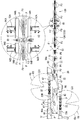
以下に、実施形態について図1〜6を用いて説明する。図1、2に示す本実施形態における横形製袋充填機は、フィルムロール(不図示)が配設されたフィルム供給部(不図示)と、該フィルム供給部より上方位置に配設されており、フィルムロール(不図示)から引き出された帯状フィルムFを筒状に成形する製袋手段60と、前処理工程12から搬送されてきた複数の袋詰品P(個装品)を一包装単位の集合品PUとして、製袋手段60において筒状になる前の上方が開放した断面U字形のフィルムF1に向けて所定の間隔を空けて供給する供給手段20と、集合品PUが供給された断面U字形のフィルムF1の幅方向両端縁部を重合した重合部に縦シールを施して筒状フィルムF2とする縦シール手段70と、筒状フィルムF2中に置かれた集合品PUの搬送方向(前後方向)における前後位置で、その筒状フィルムF2の搬送方向と交差する上下方向に沿って筒状フィルムF2に横シールを施す横シール手段80と、横シールを施す際に筒状フィルムF2における横シール部の前後位置を下方から上方に向けて折り込む折込手段84と、横シール手段80から進退可能に配設され筒状フィルムF2における横シールを施した箇所を切断して一包装単位の集合品PUを内包した自立性を有した包装形態F4(図6参照)とする不図示の切断手段と、その包装形態F4を後処理工程に向けて排出する排出コンベヤ120などを備えている。
Hereinafter, an embodiment will be described with reference to FIGS. The horizontal bag making and filling machine in the present embodiment shown in FIGS. 1 and 2 is provided with a film supply unit (not shown) in which a film roll (not shown) is arranged, and a position above the film supply unit. , A bag making means 60 for forming a belt-like film F drawn from a film roll (not shown) into a cylindrical shape, and a plurality of bagged products P (individual items) conveyed from the
供給手段20は、図1に示すように搬送方向(前後方向)に沿って互いが搬送方向にずれて配設されていると共に搬送方向に交差する左右方向に互いが離間して配設された2機のバケットコンベヤ30A、30Bと、両バケットコンベヤ30A、30Bの間に配設された供給コンベヤ22と、各バケットコンベヤ30A、30Bの近傍に夫々に対応して配設された2機のロボットRA、RB(図1のロボットRA、RBはロボットにおけるハンド部Hの作動範囲EA、EBによって略体化されている)を備える。
As shown in FIG. 1, the supply means 20 are disposed so as to be shifted from each other in the transport direction along the transport direction (front-rear direction) and are spaced apart from each other in the left-right direction intersecting the transport direction. Two
各バケットコンベヤ30A、30Bは、図1に示すように搬送方向に並んだ複数の区画部32の夫々に前処理工程12から搬送されてくる袋詰品Pを受け入れ位置で、順次、受入れるごとに、搬送方向前方に区画部32一つ分、回動させ区画部32ごとに収容した複数の袋詰品Pを向きを揃えて搬送方向に一列に並べるよう不図示の制御手段で駆動制御されるよう構成されている。
Each time the
供給コンベヤ22は、図1、2に示すようにロボットRA、RBのハンド部H(図4参照)が一包装単位の集合品PUを載置する第1コンベヤ40と、その第1コンベヤ40から受け渡された集合品PUを一定の間隔(一包装袋長さ間隔)でその搬送下流に接続された製袋手段60に向けて搬送する第2コンベヤ50(本発明の搬送コンベヤに相当する)と、集合品PUを載置し搬送する第1コンベヤ40における搬送路40a及び第2コンベヤ50における搬送路50aの両側上方で夫々集合品PUを支持しつつ搬送するサイドベルトコンベヤ42、52を備えている。なお、第1コンベヤ40側のサイドベルトコンベヤ42は、ベルトの弛みを防止するために、前後方向に2つのコンベヤが接続されている。第2コンベヤ50と、第2コンベヤ50の搬送路50aの両側で集合品PUを支持するサイドベルトコンベヤ52は、不図示のフィルム供給部によるフィルム供給に同期し且つフィルム搬送手段130により筒状フィルムF2を搬送する速度と常に同速度で集合品PUが搬送されるように第2コンベヤ50を駆動するモータM2やサイドベルトコンベヤ52を駆動するモータ(不図示)等からなる第2駆動手段により駆動制御される。第1コンベヤ40と、第1コンベヤ40の搬送路40aの両側で集合品PUを支持するサイドベルトコンベヤ42は、互いが常に同じ速度で集合品PUを搬送し、第2コンベヤ50に集合品PUを受け渡す際に前後の集合品PUの間隔が一包装袋長さ間隔になるよう第1コンベヤ40を駆動するモータM1やサイドベルトコンベヤ42を駆動するモータ(不図示)等からなる第1駆動手段により駆動制御される。具体的には、図2に示すように第2コンベヤ50の側方に配設された光電センサなどからなる製品検知手段Sにより第2コンベヤ50の搬送路50a上を搬送されてきた集合品PUの到来を検知すると、その検知情報と第1、第2コンベヤ40、50に夫々配設されたエンコーダEnから得られた搬送位置情報に基づき、製品検知手段Sに到来した集合品PUよりN−1個分後続の集合品PUが第2コンベヤ50に乗り移った際に、先行の集合品PUとの間隔が一包装袋長さになるようN個分後続の集合品PUを搬送する第1コンベヤ40及びサイドベルトコンベヤ42の搬送速度を増速或は減速するなどの駆動制御がなされる。この増速或は減速する制御によりN個分後続の集合品PUを第2コンベヤ50に渡すまでに1つ先行の集合品PUとの間隔が空きすぎていて一包装袋長さに調整できない場合には、二つ或はそれ以上の包装袋長さ分の間隔にする。
As shown in FIGS. 1 and 2, the
2機のロボットRA、RBは、図1に示すようにバケットコンベヤ30A、30Bの区画部32に収容された複数の袋詰品Pを一包装単位の集合品PUずつに把持(保持)して第1コンベヤ40の搬送路40a上に載置するものである。2機のロボットRA、RBは、図1に示すように作動中心EA1、EB1に少なくとも一以上の間接を有するアーム部(不図示)がそれぞれ配設されており、その先端が互いに干渉することがない同図の作動範囲EA、EB内の上下左右方向に自由移動し得るように構成されている。かかるアーム部の先端には、図4に示すハンド部Hを備えている。ハンド部Hは、長尺状の第1支持部100を有しており、アーム部に設けられた不図示のサーボモータ等の駆動手段によってかかる第1支持部100の長手方向の中間位置である中心102周り100Eでアーム部に対して回転可能に支持されている。第1支持部100の下方には、一対の中間支持部101が第1支持部100の長手方向に沿ってスライド移動可能に支持されている。各中間支持部101には、第2支持部104が中心102からそれぞれ同一距離だけ離間した中心106に旋回範囲104Eに亘って旋回し得るように支持されている。第1支持部100と中間支持部101の間には、エアシリンダなどの駆動源HCの伸縮作動に伴い中心102に対し各中間支持部101の中心106を近接離間させるリンク接続してなる駆動機構HC1が介装されている。また、各第2支持部104は中間支持部101に配設されたエアシリンダなどの駆動源HBの伸縮作動に伴い旋回範囲104Eに亘って旋回する際に、それぞれの第2支持部104の下方に配設された3対の把持部HAがギヤ機構HB1によって同じ向きに同角度自転するように構成されている。なお、各把持部HAは、不図示のエアシリンダへのエア給排によって袋詰品Pを把持解放する。
As shown in FIG. 1, the two robots RA and RB hold (hold) a plurality of packaged products P accommodated in the
ロボットRA、RBが各ハンド部Hをバケットコンベヤ30A、30Bの上方で各バケットコンベヤ30A、30Bの搬送方向に第1支持部100の長手方向が沿うように向けて、バケットコンベヤ30A、30Bの区画部32に収容された計6つの袋詰品Pを計6組の把持部HAでまとめて把持して袋詰品Pを区画部32から取り出した後に、図5(A)に示すようにハンド部H(図4参照)によって把持された袋詰品Pは、駆動源HB(図4参照)の作動によって2つの第2支持部104が図5(B)のように中心106回りを旋回する際に、ギヤ機構HB1(図4参照)が回転し、第2支持部104に対し把持部HA(図4参照)がそれぞれ回転することから第2支持部104ごとに第2支持部104の長手方向に沿って1列に整列すると共に整列した中央の袋詰品Pに対し前後の袋詰品Pの一部が重なりあう状態(いわゆる刺身重ね状態)になる。なお袋詰品Pの表裏は全て同じ向きに揃えられている。そして、2組の袋詰品Pは、駆動源HC(図4参照)の作動により駆動機構HC1が回転し両中間支持部101が中心102に向けて接近することによって図5(C)に示すように3行×2列からなる一つの集合品PUとなる。そして、次に第1コンベヤ40における搬送方向に集合品PUにおける袋詰品Pの整列方向が向くようにアーム部の先端で図5(D)のようにハンド部Hを略90°回転させて集合品PUが第1コンベヤ40(図1参照)に載置される。
The robots RA and RB partition the
製袋手段60は、図3に示すように底壁62とその底壁62の両側から上方に延出した側壁64によって上方が開口している。各側壁64は、第2コンベヤ50の搬送路50aの終端部に接近して配設された際に底壁62の前端部と並んで、第2コンベヤ50の終端部に最も接近することになる端部64aと、その端部64aの上端から後方側に向かって傾斜した傾斜部64bを有している。また、各側壁64の外側には、フィルムロール(不図示)から引き出された帯状フィルムFを側壁64の傾斜部64bと端部64a並びに底壁62の前端部に向けて案内する板状のフィルムガイド66が取付けられている。なお、フィルムガイド66の前方側端部66aは、側壁64の端部64aより後方側に配設される。これにより底壁62と各側壁64の端部64aとの接続で角形状に形成されてなる各突部68がフィルムガイド66によって案内されてくるフィルムF’に折掛線FLとしての傷を付ける癖付手段として機能する。即ち、製袋手段60は、底壁62と両側壁64によって帯状フィルムFを折り返して、上方が開放した断面U字状に成形すると共に、その断面U字形のフィルムF1の底には各突部68によって筒状フィルムF2の搬送方向に沿って2本の折掛線FLとしての傷が継続してつけられる。
As shown in FIG. 3, the bag making means 60 is opened at the top by a
縦シール手段70は、集合品PUを内包した断面U字形のフィルムF1をフィルム搬送手段130としてのサイドベルトコンベヤ134(図1、2参照)によって搬送する際に搬送路の上方で断面U字形のフィルムF1の両端縁部を重合した重合部に搬送方向に沿って縦シールを施す。
The vertical sealing means 70 has a U-shaped section above the conveying path when the U-shaped film F1 containing the assembly PU is conveyed by the side belt conveyor 134 (see FIGS. 1 and 2) as the
横シール手段80は、筒状フィルムF2の両側に対向した一対のシール体82が周知の駆動連係手段(不図示)からの駆動によって互いに左右方向(搬送方向と直行する水平方向)に近接離間すると共に搬送方向に移動し得るよう構成されており、一対のシール体82は内包された前後の集合品PUの間の筒状フィルムF2を挟持しつつ搬送方向に移動して横シールを施した後、元の位置に復帰し1包装サイクルを終える所謂ボックスモーション方式からなるシール装置であり、この横シール手段80の1包装サイクルの動きは一包装袋長さ分のフィルム搬送に同調するように制御される。なお、両シール体82が近接する際には両シール体82の接近を妨げないよう、両シール体82の上流側に配設されたフィルム搬送手段130としてのコンベヤ132(図2拡大図参照)と、下流側に配設されたコンベヤ120(図2拡大図参照)は、周知の駆動連係手段(不図示)によって互いに離間するようになっている。
In the lateral seal means 80, a pair of
図1に示すように、横シール手段80のシール体82に対し搬送方向の上流側と下流側に、押圧手段90A、90Bが取付けられている。押圧手段90A、90Bは、一対のシール体82が筒状フィルムF2を挟持する直前にエアシリンダなどの駆動手段92A、92Bによりスポンジなどからなる押圧部材94A、94Bを筒状フィルムF2に向けて移動させて、筒状フィルムF2内の空気を搬送上流に向けて排出すると共に、一対のシール体82が筒状フィルムF2を挟持し横シールを施す際に内包された集合品PU等の位置ずれを防ぐために集合品PUを押えるように作動タイミングが設定されている。
As shown in FIG. 1, pressing means 90 </ b> A and 90 </ b> B are attached to the
折込手段84は、搬送路の下方であって一対のシール体82の間に配設されている。折込手段84は、一対の爪部材86が搬送路に進退し得るように構成されており、一対のシール体82が筒状フィルムF2を挟持する作動に先立って爪部材86を横シール部FSが形成される箇所付近の筒状フィルムF2に当接させて、筒状フィルムF2を上方に向けて内側に折り込む。
The folding means 84 is disposed below the conveyance path and between the pair of
次に、上述した横形製袋充填機の一連の作用を説明する。なお本実施例では、例えば、袋詰品Pの中央が円弧状を呈し両端部より厚く隆起した厚みが不均一で安定性に欠ける袋詰品Pが、起立姿勢で並べて搬送されると共に、図1に示すように、搬送方向(前後方向)に3個、搬送方向に交差する方向(左右方向)に2個からなる集合品PUとして一包装単位として一括包装する場合を例示する。図1、2に示すように前処理工程12から搬送されてくる袋詰品Pが、各バケットコンベヤ30A、30Bの区画部32ごとにそれぞれ収容されると、ロボットRA、RBは、各ハンド部Hの各把持部HAによってバケットコンベヤ30A、30Bの区画部32に一列に収容されて並んだ袋詰品Pを先頭から一つおきに計6つ一括して把持(一括保持)し、前述のごとく、6つの袋詰品Pからなる集合品PUにして、第1コンベヤ40の搬送路40aに載置する。ロボットRAは第1コンベヤ40の搬送路40aの上流側に集合品PUを載置し、ロボットRBは、第1コンベヤ40の搬送路40aの下流側に集合品PUを載置するにあたっては、第1コンベヤ40に配設されたエンコーダEnから得られた搬送位置情報に基づき、第1コンベヤ40の搬送路40aにおいて一包装袋長さに対応して設定された間隔ごとに定められた位置に集合品PUを載置するように各ロボットRA、RBのアーム部を第1コンベヤ40の搬送速度と同速度で移動させつつ集合品PUを載置するもので、ロボットRAは、集合品PUを第1コンベヤ40に二包装袋長さに対応して設定された間隔で載置し、ロボットRBは集合品PUをロボットRAにより載置され搬送されてきた前後の集合品PUの間に載置する。なお、第1コンベヤ40は、ハンド部Hがサイドベルトコンベヤ42に干渉することなく集合品PUを載置し得るように対向する2対のサイドベルトコンベヤ42の間隔が設定されることから搬送路40aが広く構成されている。そのため、第1コンベヤ40の搬送路40aに載置された集合品PUは、2対のサイドベルトコンベヤ42のいずれか一方側に倒れた状態で搬送され第2コンベヤ50に一包装袋長さ間隔ごとに受け渡される。第2コンベヤ50に受け渡された集合品PUは、2対のサイドベルトコンベヤ52の間隔が搬送方向の下流側に向かって序々に狭くなることで、集合品PUが序々に起立姿勢になりつつ、製袋手段60によって成形された断面U字形のフィルムF1に載り移る。製袋手段60においては、断面U字形のフィルムF1が集合品PUの一部を覆うように支持しつつ集合品PUを搬送することにより、集合品PUは、乱れることなく、起立姿勢がそのまま維持される。そして、横シール手段80の付近まで集合品PUはフィルム搬送手段130としてのサイドベルトコンベヤ134によって起立姿勢が維持されつつ搬送される。その途中、縦シール手段70により断面U字形のフィルムF1の両端縁部に縦シールが施されると、集合品PUは筒状フィルムF2内に内包された状態になる。そして横シール手段80によって筒状フィルムF2に横シールが施され横シール部FSが切断されると、袋詰品P6つが一包装単位の集合品PUとして一括包装された包装形態F4となって搬出コンベヤ120によって後処理工程に向けて排出される。このようにして得られた包装形態F4は、折込手段84によって袋の底部にガセットが成形されており、また製袋手段60の各突部68によってつけられた折掛線FL(図6参照)が袋の底面と側面の境界線になって底面が明瞭に四角形状の輪郭とされ、更に集合品PUにおける各袋詰品Pの表面が向く方向が揃った角底形状の自立性を有した包装形態F4となる。
Next, a series of operations of the above-described horizontal bag making and filling machine will be described. In the present embodiment, for example, the center of the packaged product P has an arc shape and is thicker than the two end portions, and the packaged product P having a non-uniform thickness and lacking stability is conveyed side by side in a standing posture. As illustrated in FIG. 1, an example of collectively packaging as a single packaging unit as a collective PU having three in the transport direction (front-rear direction) and two in the direction crossing the transport direction (left-right direction) is illustrated. As shown in FIGS. 1 and 2, when the packed product P conveyed from the
以上のことから、袋詰品P中央が両端部より厚いなど厚みが不均一な袋詰品P同士を重ねた際に位置ずれが生じたり、袋詰品P自体が自立性を有さないことから倒れたりするなど安定性に欠ける袋詰品Pなどをまとめて包装することができると共に自立性を有した包装形態を得ることが可能な横形製袋充填機を提供することができる。なお、袋の周辺三方又は四方がシールされ、各シール部の剛性が比較的高くなった袋詰品Pを起立姿勢にする際には、シール部が袋詰品Pを支えることから、自立性を有した包装形態F4を得るにあたって、より好ましい。
・第2コンベヤ50(搬送コンベヤ)とサイドベルトコンベヤ52が搬送方向にフィルム搬送手段130によって搬送されるフィルム搬送速度と同速度で集合品PUを製袋手段60に向けて搬送することから、集合品PUを構成する各袋詰品Pの前後方向及び左右方向に重なり状態などが乱れることなく、起立姿勢で重なった集合品PUを製袋手段60で成形された断面U字形のフィルムF1に渡すことができる。
・ハンド部Hが一列に並んだ所要数の袋詰品Pを保持しつつそれら袋詰品Pを前後及び左右に重ねて集合品PUにすることから、集合品PUにするまでに複数の袋詰品Pを搬送する搬送経路を短くすることができるなど装置全体を小型化或は簡素化することができる。
・各ハンド部Hがバケットコンベヤ30A、30Bから一列に並んだ袋詰品Pを一つ置きに把持することからハンド部Hの把持部HAが袋詰品Pを離す際などに隣の把持部HAとのとの干渉を防ぎつつ確実に保持することができる。
From the above, misalignment occurs when bag-shaped products P with non-uniform thickness such as the center of the bag-shaped product P is thicker than both ends, or the bag-shaped product P itself does not have independence. Thus, it is possible to provide a horizontal bag making and filling machine that can package a packaged product P or the like that lacks stability, such as falling from the top, and can obtain a self-supporting packaging form. It should be noted that when the bagged product P, in which the three or four sides of the bag are sealed and the rigidity of each seal part is relatively high, is put in an upright posture, the seal part supports the bagged product P, so that it is self-supporting. In obtaining the packaging form F4 having
The second conveyor 50 (conveyance conveyor) and the
-While holding the required number of packaged products P in which the hand portions H are arranged in a row, the packaged products P are stacked in the front and rear and left and right to form a collective product PU. The entire apparatus can be reduced in size or simplified, for example, the conveyance path for conveying the filling P can be shortened.
-Since each hand part H grips every other packed product P arranged in a row from the
(変更例)
・供給手段としては、製袋手段60の上流側に配設されたコンベヤをなくし、製袋手段60によって断面U字形のフィルムF1にロボットRA、RBがフィルム搬送方向にフィルム搬送速度と同速度で移動しながら集合品PUを供給するようにしてもよい。なお、間欠包装において停止中のフィルムに集合品PUを供給することもこの技術に含まれる。
・フィルム供給部において折目付け装置を設けてフィルムの搬送方向に折掛線としての傷を付けてもよいが、本実施形態のように製袋手段で折掛線としての傷を付ける場合には、フィルム供給部に別途の折目付け装置を設ける必要がなく、装置全体を小型化或は簡素化した構成で自立性を有した包装形態を得ることが可能となる。なお、本実施形態に限定されず、このように製袋手段で折掛線としての傷を付けて自立性を有した角底形状の包装形態を得る技術は、本実施形態に限られず他の製袋充填機にも適用可能である。その場合の内容物は個装品に限られるものではなく単品であってもよく、また、製袋手段60におけるフィルムガイド66は必須の構成ではない。すなわち、製袋手段で折掛線としての傷を付ける場合において、製袋手段にフィルムガイドを構成しなくても、下方から各突部68に向けて案内されてくる帯状フィルムの進入角を調整して、各突部68を折掛線としての傷を付ける癖付手段として機能させてもよい。
・袋詰品の保持する態様は、把持部によって把持する構成に限られず種々の態様を適用可能である。たとえば、袋詰品を吸着して保持する構成であってもよい。
・脱気用押圧手段90A、90Bは、同時に作動する態様、別々に作動する態様のいずれであってもよい。
・集合品は、3行2列に限られず種々な態様に適用可能である。
・ロボット、バケットコンベヤの数などは、限定されない。
(Example of change)
As the supply means, the conveyor disposed upstream of the bag making means 60 is eliminated, and the robot RA and RB are moved to the film F1 in the film carrying direction at the same speed as the film carrying speed by the bag making means 60. The collective product PU may be supplied while moving. Note that this technique also includes supplying the aggregate PU to a film that is stopped in intermittent packaging.
・ A crease device may be provided in the film supply unit to scratch the folding line in the film transport direction, but in the case of scratching as a folding line by the bag making means as in this embodiment In addition, it is not necessary to provide a separate crease device in the film supply unit, and it is possible to obtain a packaging form having self-supporting properties with a configuration in which the entire device is downsized or simplified. Note that the present invention is not limited to this embodiment, and the technology for obtaining a square bottom-shaped packaging form having a self-standing property by scratching as a folding line by the bag making means is not limited to this embodiment, It can also be applied to bag making and filling machines. The contents in that case are not limited to individual items but may be single items, and the
-The aspect which a bagging product hold | maintains is not restricted to the structure hold | gripped by a holding part, A various aspect is applicable. For example, the structure which adsorb | sucks and hold | maintains a bagging product may be sufficient.
-The deaeration pressing means 90A, 90B may be either of an aspect that operates simultaneously and an aspect that operates separately.
-Collective goods are not restricted to 3 rows 2 columns, but can be applied to various aspects.
-The number of robots and bucket conveyors is not limited.
以上、本発明の実施形態について説明したが、本発明の横形製袋充填機は、本実施形態に限定されず、その他各種の形態で実施することができるものである。 As mentioned above, although embodiment of this invention was described, the horizontal bag making and filling machine of this invention is not limited to this embodiment, It can implement with other various forms.
F:帯状フィルム F1:断面U字形のフィルム F2:筒状フィルム
P:袋詰品 PU:集合品 20:供給手段 30A、30B:バケットコンベヤ
32:区画部 50:第2コンベヤ(搬送コンベヤ) 52:サイドベルトコンベヤ
50a:搬送路 RA、RB:ロボット H:ハンド部 70:縦シール手段
80:横シール手段 84:折込手段
F: Band-shaped film F1: Film having a U-shaped cross section F2: Cylindrical film P: Packed product PU: Collected product 20: Supply means 30A, 30B: Bucket conveyor 32: Partition 50: Second conveyor (conveyor) 52:
Claims (5)
機体の下方に配置した供給源から供給される帯状フィルムの幅方向における両端縁部が上方で開放した断面U字形のフィルムに向けて、前記ハンド部によって起立姿勢で前記断面U字形のフィルムの搬送方向における前後及び左右に重なった所要数の袋詰品を集合品として保持しつつフィルム搬送速度と同速度で供給する供給手段と、
前記断面U字形のフィルムの側壁で前記集合品を支持しつつ、該フィルムの両端縁部を重合して縦シールを施した筒状フィルムに対し、該筒状フィルムに内包された前記集合品の前後位置で、前記搬送方向と交差する上下方向に横シールを施す横シール手段と、
前記横シールを施す際に前記筒状フィルムにおける横シール部の前後位置を下方から上方に向けて折り込む折込手段と、を備える横形製袋充填機。 A robot having a hand part that can freely move in a three-dimensional space;
Conveying the U-shaped film in an upright posture by the hand part toward the U-shaped film whose both end edges in the width direction of the strip-shaped film supplied from the supply source arranged below the machine body are opened upward Supply means for supplying the required number of bagged products overlapping the front and rear and left and right in the direction as a collective product at the same speed as the film transport speed;
While supporting the assembled product on the side wall of the U-shaped cross-section film, the cylindrical film in which both edge portions of the film are polymerized and subjected to vertical sealing, the assembled product enclosed in the tubular film Horizontal sealing means for applying a horizontal seal in the vertical direction intersecting the conveying direction at the front-rear position;
A horizontal bag making and filling machine comprising: folding means that folds the front and rear positions of the horizontal seal portion of the cylindrical film upward from the bottom when the horizontal seal is applied.
該搬送コンベヤの搬送路の両側における該搬送路より上方で前記集合品を支持しつつ前記フィルム搬送速度と同速度で搬送するサイドベルトコンベヤを備えることを特徴とする請求項1に記載の横形製袋充填機。 The supply means transports the assembly in the standing posture placed by the hand unit at the same speed as the film transport speed, and supplies the assembly to the U-shaped cross-section film,
2. The horizontal product according to claim 1, further comprising a side belt conveyor that conveys the assembly at the same speed as the film conveyance speed while supporting the assembly above the conveyance path on both sides of the conveyance path of the conveyance conveyor. Bag filling machine.
The bucket conveyor conveys the packed products in a row in an upright position, and the hand unit holds the required number of the packed products every other one and maintains the standing posture of the held packed products. The horizontal bag making and filling machine according to claim 4, further comprising a grip portion capable of changing a direction of the bagged product.
Priority Applications (1)
| Application Number | Priority Date | Filing Date | Title |
|---|---|---|---|
| JP2013107048A JP5859482B2 (en) | 2013-05-21 | 2013-05-21 | Horizontal bag making and filling machine |
Applications Claiming Priority (1)
| Application Number | Priority Date | Filing Date | Title |
|---|---|---|---|
| JP2013107048A JP5859482B2 (en) | 2013-05-21 | 2013-05-21 | Horizontal bag making and filling machine |
Publications (2)
| Publication Number | Publication Date |
|---|---|
| JP2014227182A JP2014227182A (en) | 2014-12-08 |
| JP5859482B2 true JP5859482B2 (en) | 2016-02-10 |
Family
ID=52127398
Family Applications (1)
| Application Number | Title | Priority Date | Filing Date |
|---|---|---|---|
| JP2013107048A Active JP5859482B2 (en) | 2013-05-21 | 2013-05-21 | Horizontal bag making and filling machine |
Country Status (1)
| Country | Link |
|---|---|
| JP (1) | JP5859482B2 (en) |
Families Citing this family (3)
| Publication number | Priority date | Publication date | Assignee | Title |
|---|---|---|---|---|
| CN108584002B (en) * | 2017-12-20 | 2023-09-08 | 紫光日东科技(深圳)有限公司 | Film packaging sealing and cutting machine |
| CN109515854A (en) * | 2018-12-14 | 2019-03-26 | 广州市永合祥自动化设备科技有限公司 | Bagging system and bagging method |
| JP7093906B1 (en) * | 2021-03-26 | 2022-06-30 | 株式会社生産日本社 | Outer bag containing product, bag supply device and supply method |
Family Cites Families (4)
| Publication number | Priority date | Publication date | Assignee | Title |
|---|---|---|---|---|
| JP2836948B2 (en) * | 1990-11-07 | 1998-12-14 | 日本特許管理株式会社 | Production of upright bags with zippers and automatic filling method for them |
| JPH08217015A (en) * | 1995-02-10 | 1996-08-27 | Oshio Sangyo Kk | Package of solid content and its manufacturing method and device |
| JP4436517B2 (en) * | 2000-01-31 | 2010-03-24 | 株式会社川島製作所 | Self-standing bag making and filling and packaging equipment |
| JP5250514B2 (en) * | 2009-09-07 | 2013-07-31 | 株式会社フジキカイ | Article supply equipment |
-
2013
- 2013-05-21 JP JP2013107048A patent/JP5859482B2/en active Active
Also Published As
| Publication number | Publication date |
|---|---|
| JP2014227182A (en) | 2014-12-08 |
Similar Documents
| Publication | Publication Date | Title |
|---|---|---|
| RU2608715C2 (en) | Method and apparatus for inserting packages into cartons | |
| CA2715882C (en) | Method and device for inserting (tube) bags into cartons | |
| JP4913757B2 (en) | Machine for automatically packaging products into cardboard boxes | |
| JP6261514B2 (en) | Method and apparatus for manufacturing a pack with shrink wrap film | |
| CA2731174C (en) | Machine for cartoning products | |
| JP2011526868A5 (en) | ||
| AU2008305799B2 (en) | Device and method for filling of a container | |
| ITMI20131355A1 (en) | MACHINE, PROCEDURE, CONTAINER AND ENVELOPE FOR PACKAGING TETRAEDRIC PRODUCTS | |
| JP5859482B2 (en) | Horizontal bag making and filling machine | |
| JP6914496B2 (en) | Automatic boxing device for continuous bag | |
| JP5409140B2 (en) | PTP sheet group supply device and product supply system using the same | |
| JP6379012B2 (en) | Goods transfer device | |
| JP7059293B2 (en) | Filling machine for filling flexible pouch-type packages | |
| JP5911281B2 (en) | Bag opening device | |
| JP2011225251A (en) | Boxing system in corrugated fiberboard box | |
| JP5483619B2 (en) | Boxing equipment | |
| JP5158822B2 (en) | Bag seal device | |
| JP6255173B2 (en) | Inversion device and container filling device | |
| JP7399487B2 (en) | Conveyance device | |
| JP7194454B2 (en) | cartoning equipment | |
| JP7305282B2 (en) | Pushing device and cartoning device with the same | |
| JP6978085B2 (en) | Goods supply device | |
| JP4609614B2 (en) | Automatic product packaging method and apparatus | |
| US10737454B2 (en) | Method and machine for quality control inspection of pinch bottom and flat bottom bags | |
| JP6969967B2 (en) | Boxing device for pouch containers with spout |
Legal Events
| Date | Code | Title | Description |
|---|---|---|---|
| A621 | Written request for application examination |
Free format text: JAPANESE INTERMEDIATE CODE: A621 Effective date: 20150115 |
|
| A977 | Report on retrieval |
Free format text: JAPANESE INTERMEDIATE CODE: A971007 Effective date: 20151109 |
|
| TRDD | Decision of grant or rejection written | ||
| A01 | Written decision to grant a patent or to grant a registration (utility model) |
Free format text: JAPANESE INTERMEDIATE CODE: A01 Effective date: 20151208 |
|
| A61 | First payment of annual fees (during grant procedure) |
Free format text: JAPANESE INTERMEDIATE CODE: A61 Effective date: 20151216 |
|
| R150 | Certificate of patent or registration of utility model |
Ref document number: 5859482 Country of ref document: JP Free format text: JAPANESE INTERMEDIATE CODE: R150 |
|
| R250 | Receipt of annual fees |
Free format text: JAPANESE INTERMEDIATE CODE: R250 |
|
| R250 | Receipt of annual fees |
Free format text: JAPANESE INTERMEDIATE CODE: R250 |
|
| R250 | Receipt of annual fees |
Free format text: JAPANESE INTERMEDIATE CODE: R250 |