JP5859016B2 - Electrochemically conductive article comprising a current collector with a conductive coating and method for manufacturing the same - Google Patents
Electrochemically conductive article comprising a current collector with a conductive coating and method for manufacturing the same Download PDFInfo
- Publication number
- JP5859016B2 JP5859016B2 JP2013539915A JP2013539915A JP5859016B2 JP 5859016 B2 JP5859016 B2 JP 5859016B2 JP 2013539915 A JP2013539915 A JP 2013539915A JP 2013539915 A JP2013539915 A JP 2013539915A JP 5859016 B2 JP5859016 B2 JP 5859016B2
- Authority
- JP
- Japan
- Prior art keywords
- current collector
- porous metal
- carbon
- powder
- conductive
- Prior art date
- Legal status (The legal status is an assumption and is not a legal conclusion. Google has not performed a legal analysis and makes no representation as to the accuracy of the status listed.)
- Expired - Fee Related
Links
- 238000000576 coating method Methods 0.000 title claims description 46
- 239000011248 coating agent Substances 0.000 title claims description 44
- 238000000034 method Methods 0.000 title description 29
- 238000004519 manufacturing process Methods 0.000 title description 11
- OKTJSMMVPCPJKN-UHFFFAOYSA-N Carbon Chemical compound [C] OKTJSMMVPCPJKN-UHFFFAOYSA-N 0.000 claims description 87
- 229910052751 metal Inorganic materials 0.000 claims description 49
- 239000002184 metal Substances 0.000 claims description 49
- 239000011888 foil Substances 0.000 claims description 43
- 229910052782 aluminium Inorganic materials 0.000 claims description 27
- XAGFODPZIPBFFR-UHFFFAOYSA-N aluminium Chemical compound [Al] XAGFODPZIPBFFR-UHFFFAOYSA-N 0.000 claims description 27
- 239000000843 powder Substances 0.000 claims description 25
- 229910002804 graphite Inorganic materials 0.000 claims description 19
- 239000010439 graphite Substances 0.000 claims description 19
- 238000005498 polishing Methods 0.000 claims description 19
- 239000011230 binding agent Substances 0.000 claims description 10
- 239000003973 paint Substances 0.000 claims description 5
- 239000002904 solvent Substances 0.000 claims description 3
- 239000003990 capacitor Substances 0.000 description 47
- 229910052799 carbon Inorganic materials 0.000 description 43
- HBBGRARXTFLTSG-UHFFFAOYSA-N Lithium ion Chemical compound [Li+] HBBGRARXTFLTSG-UHFFFAOYSA-N 0.000 description 14
- 229910001416 lithium ion Inorganic materials 0.000 description 14
- 230000008569 process Effects 0.000 description 12
- 239000000463 material Substances 0.000 description 11
- 239000000758 substrate Substances 0.000 description 11
- 239000003792 electrolyte Substances 0.000 description 9
- 238000004146 energy storage Methods 0.000 description 7
- 230000033001 locomotion Effects 0.000 description 6
- 239000011149 active material Substances 0.000 description 5
- 102100026827 Protein associated with UVRAG as autophagy enhancer Human genes 0.000 description 4
- 101710102978 Protein associated with UVRAG as autophagy enhancer Proteins 0.000 description 4
- 238000010586 diagram Methods 0.000 description 4
- 150000002500 ions Chemical class 0.000 description 4
- 239000000203 mixture Substances 0.000 description 4
- 239000002245 particle Substances 0.000 description 4
- 238000000926 separation method Methods 0.000 description 4
- WEVYAHXRMPXWCK-UHFFFAOYSA-N Acetonitrile Chemical compound CC#N WEVYAHXRMPXWCK-UHFFFAOYSA-N 0.000 description 3
- WHXSMMKQMYFTQS-UHFFFAOYSA-N Lithium Chemical compound [Li] WHXSMMKQMYFTQS-UHFFFAOYSA-N 0.000 description 3
- 230000009471 action Effects 0.000 description 3
- 230000006870 function Effects 0.000 description 3
- 229910052744 lithium Inorganic materials 0.000 description 3
- 230000007480 spreading Effects 0.000 description 3
- 238000003892 spreading Methods 0.000 description 3
- RYGMFSIKBFXOCR-UHFFFAOYSA-N Copper Chemical compound [Cu] RYGMFSIKBFXOCR-UHFFFAOYSA-N 0.000 description 2
- VEXZGXHMUGYJMC-UHFFFAOYSA-N Hydrochloric acid Chemical compound Cl VEXZGXHMUGYJMC-UHFFFAOYSA-N 0.000 description 2
- PXHVJJICTQNCMI-UHFFFAOYSA-N Nickel Chemical compound [Ni] PXHVJJICTQNCMI-UHFFFAOYSA-N 0.000 description 2
- 239000004677 Nylon Substances 0.000 description 2
- 238000010521 absorption reaction Methods 0.000 description 2
- 238000005452 bending Methods 0.000 description 2
- 150000001721 carbon Chemical class 0.000 description 2
- 239000003575 carbonaceous material Substances 0.000 description 2
- 239000002131 composite material Substances 0.000 description 2
- 238000009792 diffusion process Methods 0.000 description 2
- 238000009826 distribution Methods 0.000 description 2
- 239000011262 electrochemically active material Substances 0.000 description 2
- 238000005530 etching Methods 0.000 description 2
- 239000000835 fiber Substances 0.000 description 2
- 229920001778 nylon Polymers 0.000 description 2
- 238000006748 scratching Methods 0.000 description 2
- 230000002393 scratching effect Effects 0.000 description 2
- 238000012876 topography Methods 0.000 description 2
- 125000003821 2-(trimethylsilyl)ethoxymethyl group Chemical group [H]C([H])([H])[Si](C([H])([H])[H])(C([H])([H])[H])C([H])([H])C(OC([H])([H])[*])([H])[H] 0.000 description 1
- 229920000049 Carbon (fiber) Polymers 0.000 description 1
- 102000010029 Homer Scaffolding Proteins Human genes 0.000 description 1
- 108010077223 Homer Scaffolding Proteins Proteins 0.000 description 1
- 229920005830 Polyurethane Foam Polymers 0.000 description 1
- 229910000676 Si alloy Inorganic materials 0.000 description 1
- XUIMIQQOPSSXEZ-UHFFFAOYSA-N Silicon Chemical compound [Si] XUIMIQQOPSSXEZ-UHFFFAOYSA-N 0.000 description 1
- 229910001128 Sn alloy Inorganic materials 0.000 description 1
- 239000003082 abrasive agent Substances 0.000 description 1
- 238000009825 accumulation Methods 0.000 description 1
- 239000002390 adhesive tape Substances 0.000 description 1
- 230000008901 benefit Effects 0.000 description 1
- 230000005540 biological transmission Effects 0.000 description 1
- 230000015572 biosynthetic process Effects 0.000 description 1
- 239000000872 buffer Substances 0.000 description 1
- 229910021401 carbide-derived carbon Inorganic materials 0.000 description 1
- 239000002041 carbon nanotube Substances 0.000 description 1
- 229910021393 carbon nanotube Inorganic materials 0.000 description 1
- 229910002090 carbon oxide Inorganic materials 0.000 description 1
- 230000008859 change Effects 0.000 description 1
- 230000000295 complement effect Effects 0.000 description 1
- 238000010276 construction Methods 0.000 description 1
- 229910052802 copper Inorganic materials 0.000 description 1
- 239000010949 copper Substances 0.000 description 1
- 239000011889 copper foil Substances 0.000 description 1
- ORTQZVOHEJQUHG-UHFFFAOYSA-L copper(II) chloride Chemical compound Cl[Cu]Cl ORTQZVOHEJQUHG-UHFFFAOYSA-L 0.000 description 1
- 238000013461 design Methods 0.000 description 1
- 230000000694 effects Effects 0.000 description 1
- 229920001971 elastomer Polymers 0.000 description 1
- 230000005684 electric field Effects 0.000 description 1
- 239000007772 electrode material Substances 0.000 description 1
- 238000001704 evaporation Methods 0.000 description 1
- 239000006260 foam Substances 0.000 description 1
- 239000006261 foam material Substances 0.000 description 1
- 239000002803 fossil fuel Substances 0.000 description 1
- 239000012634 fragment Substances 0.000 description 1
- 239000011521 glass Substances 0.000 description 1
- 229910021389 graphene Inorganic materials 0.000 description 1
- 238000010438 heat treatment Methods 0.000 description 1
- 230000005660 hydrophilic surface Effects 0.000 description 1
- 238000010348 incorporation Methods 0.000 description 1
- 239000011810 insulating material Substances 0.000 description 1
- 239000010416 ion conductor Substances 0.000 description 1
- 239000006233 lamp black Substances 0.000 description 1
- 230000005012 migration Effects 0.000 description 1
- 238000013508 migration Methods 0.000 description 1
- 229910003455 mixed metal oxide Inorganic materials 0.000 description 1
- 238000012986 modification Methods 0.000 description 1
- 230000004048 modification Effects 0.000 description 1
- 210000000050 mohair Anatomy 0.000 description 1
- 239000002071 nanotube Substances 0.000 description 1
- 229910052759 nickel Inorganic materials 0.000 description 1
- 239000004745 nonwoven fabric Substances 0.000 description 1
- 230000003287 optical effect Effects 0.000 description 1
- 239000005486 organic electrolyte Substances 0.000 description 1
- 238000012856 packing Methods 0.000 description 1
- 230000000704 physical effect Effects 0.000 description 1
- 230000010287 polarization Effects 0.000 description 1
- 229920000642 polymer Polymers 0.000 description 1
- 229920002635 polyurethane Polymers 0.000 description 1
- 239000004814 polyurethane Substances 0.000 description 1
- 239000011496 polyurethane foam Substances 0.000 description 1
- 229920002981 polyvinylidene fluoride Polymers 0.000 description 1
- 239000011148 porous material Substances 0.000 description 1
- 238000005381 potential energy Methods 0.000 description 1
- 239000012254 powdered material Substances 0.000 description 1
- 230000037452 priming Effects 0.000 description 1
- 238000004886 process control Methods 0.000 description 1
- 238000006479 redox reaction Methods 0.000 description 1
- 230000009467 reduction Effects 0.000 description 1
- 230000000717 retained effect Effects 0.000 description 1
- 230000002441 reversible effect Effects 0.000 description 1
- 238000004626 scanning electron microscopy Methods 0.000 description 1
- 239000010703 silicon Substances 0.000 description 1
- 239000010935 stainless steel Substances 0.000 description 1
- 229910001220 stainless steel Inorganic materials 0.000 description 1
- 238000003860 storage Methods 0.000 description 1
- -1 tetraethylammonium tetrafluoroborate Chemical compound 0.000 description 1
- 238000012546 transfer Methods 0.000 description 1
- 229910000314 transition metal oxide Inorganic materials 0.000 description 1
- 210000002268 wool Anatomy 0.000 description 1
- 239000002759 woven fabric Substances 0.000 description 1
Images


Classifications
-
- H—ELECTRICITY
- H01—ELECTRIC ELEMENTS
- H01G—CAPACITORS; CAPACITORS, RECTIFIERS, DETECTORS, SWITCHING DEVICES, LIGHT-SENSITIVE OR TEMPERATURE-SENSITIVE DEVICES OF THE ELECTROLYTIC TYPE
- H01G11/00—Hybrid capacitors, i.e. capacitors having different positive and negative electrodes; Electric double-layer [EDL] capacitors; Processes for the manufacture thereof or of parts thereof
- H01G11/04—Hybrid capacitors
-
- H—ELECTRICITY
- H01—ELECTRIC ELEMENTS
- H01G—CAPACITORS; CAPACITORS, RECTIFIERS, DETECTORS, SWITCHING DEVICES, LIGHT-SENSITIVE OR TEMPERATURE-SENSITIVE DEVICES OF THE ELECTROLYTIC TYPE
- H01G11/00—Hybrid capacitors, i.e. capacitors having different positive and negative electrodes; Electric double-layer [EDL] capacitors; Processes for the manufacture thereof or of parts thereof
- H01G11/22—Electrodes
- H01G11/26—Electrodes characterised by their structure, e.g. multi-layered, porosity or surface features
- H01G11/28—Electrodes characterised by their structure, e.g. multi-layered, porosity or surface features arranged or disposed on a current collector; Layers or phases between electrodes and current collectors, e.g. adhesives
-
- H—ELECTRICITY
- H01—ELECTRIC ELEMENTS
- H01G—CAPACITORS; CAPACITORS, RECTIFIERS, DETECTORS, SWITCHING DEVICES, LIGHT-SENSITIVE OR TEMPERATURE-SENSITIVE DEVICES OF THE ELECTROLYTIC TYPE
- H01G11/00—Hybrid capacitors, i.e. capacitors having different positive and negative electrodes; Electric double-layer [EDL] capacitors; Processes for the manufacture thereof or of parts thereof
- H01G11/22—Electrodes
- H01G11/30—Electrodes characterised by their material
- H01G11/32—Carbon-based
- H01G11/42—Powders or particles, e.g. composition thereof
-
- H—ELECTRICITY
- H01—ELECTRIC ELEMENTS
- H01G—CAPACITORS; CAPACITORS, RECTIFIERS, DETECTORS, SWITCHING DEVICES, LIGHT-SENSITIVE OR TEMPERATURE-SENSITIVE DEVICES OF THE ELECTROLYTIC TYPE
- H01G11/00—Hybrid capacitors, i.e. capacitors having different positive and negative electrodes; Electric double-layer [EDL] capacitors; Processes for the manufacture thereof or of parts thereof
- H01G11/66—Current collectors
- H01G11/68—Current collectors characterised by their material
-
- H—ELECTRICITY
- H01—ELECTRIC ELEMENTS
- H01G—CAPACITORS; CAPACITORS, RECTIFIERS, DETECTORS, SWITCHING DEVICES, LIGHT-SENSITIVE OR TEMPERATURE-SENSITIVE DEVICES OF THE ELECTROLYTIC TYPE
- H01G11/00—Hybrid capacitors, i.e. capacitors having different positive and negative electrodes; Electric double-layer [EDL] capacitors; Processes for the manufacture thereof or of parts thereof
- H01G11/66—Current collectors
- H01G11/70—Current collectors characterised by their structure
-
- H—ELECTRICITY
- H01—ELECTRIC ELEMENTS
- H01G—CAPACITORS; CAPACITORS, RECTIFIERS, DETECTORS, SWITCHING DEVICES, LIGHT-SENSITIVE OR TEMPERATURE-SENSITIVE DEVICES OF THE ELECTROLYTIC TYPE
- H01G11/00—Hybrid capacitors, i.e. capacitors having different positive and negative electrodes; Electric double-layer [EDL] capacitors; Processes for the manufacture thereof or of parts thereof
- H01G11/84—Processes for the manufacture of hybrid or EDL capacitors, or components thereof
- H01G11/86—Processes for the manufacture of hybrid or EDL capacitors, or components thereof specially adapted for electrodes
-
- H—ELECTRICITY
- H01—ELECTRIC ELEMENTS
- H01M—PROCESSES OR MEANS, e.g. BATTERIES, FOR THE DIRECT CONVERSION OF CHEMICAL ENERGY INTO ELECTRICAL ENERGY
- H01M4/00—Electrodes
- H01M4/02—Electrodes composed of, or comprising, active material
-
- H—ELECTRICITY
- H01—ELECTRIC ELEMENTS
- H01M—PROCESSES OR MEANS, e.g. BATTERIES, FOR THE DIRECT CONVERSION OF CHEMICAL ENERGY INTO ELECTRICAL ENERGY
- H01M4/00—Electrodes
- H01M4/02—Electrodes composed of, or comprising, active material
- H01M4/04—Processes of manufacture in general
- H01M4/0402—Methods of deposition of the material
-
- H—ELECTRICITY
- H01—ELECTRIC ELEMENTS
- H01M—PROCESSES OR MEANS, e.g. BATTERIES, FOR THE DIRECT CONVERSION OF CHEMICAL ENERGY INTO ELECTRICAL ENERGY
- H01M4/00—Electrodes
- H01M4/02—Electrodes composed of, or comprising, active material
- H01M4/13—Electrodes for accumulators with non-aqueous electrolyte, e.g. for lithium-accumulators; Processes of manufacture thereof
- H01M4/133—Electrodes based on carbonaceous material, e.g. graphite-intercalation compounds or CFx
-
- H—ELECTRICITY
- H01—ELECTRIC ELEMENTS
- H01M—PROCESSES OR MEANS, e.g. BATTERIES, FOR THE DIRECT CONVERSION OF CHEMICAL ENERGY INTO ELECTRICAL ENERGY
- H01M4/00—Electrodes
- H01M4/02—Electrodes composed of, or comprising, active material
- H01M4/13—Electrodes for accumulators with non-aqueous electrolyte, e.g. for lithium-accumulators; Processes of manufacture thereof
- H01M4/139—Processes of manufacture
- H01M4/1393—Processes of manufacture of electrodes based on carbonaceous material, e.g. graphite-intercalation compounds or CFx
-
- H—ELECTRICITY
- H01—ELECTRIC ELEMENTS
- H01M—PROCESSES OR MEANS, e.g. BATTERIES, FOR THE DIRECT CONVERSION OF CHEMICAL ENERGY INTO ELECTRICAL ENERGY
- H01M4/00—Electrodes
- H01M4/02—Electrodes composed of, or comprising, active material
- H01M4/64—Carriers or collectors
- H01M4/66—Selection of materials
- H01M4/661—Metal or alloys, e.g. alloy coatings
-
- H—ELECTRICITY
- H01—ELECTRIC ELEMENTS
- H01G—CAPACITORS; CAPACITORS, RECTIFIERS, DETECTORS, SWITCHING DEVICES, LIGHT-SENSITIVE OR TEMPERATURE-SENSITIVE DEVICES OF THE ELECTROLYTIC TYPE
- H01G9/00—Electrolytic capacitors, rectifiers, detectors, switching devices, light-sensitive or temperature-sensitive devices; Processes of their manufacture
- H01G9/004—Details
- H01G9/04—Electrodes or formation of dielectric layers thereon
- H01G9/042—Electrodes or formation of dielectric layers thereon characterised by the material
- H01G9/045—Electrodes or formation of dielectric layers thereon characterised by the material based on aluminium
-
- H—ELECTRICITY
- H01—ELECTRIC ELEMENTS
- H01M—PROCESSES OR MEANS, e.g. BATTERIES, FOR THE DIRECT CONVERSION OF CHEMICAL ENERGY INTO ELECTRICAL ENERGY
- H01M10/00—Secondary cells; Manufacture thereof
- H01M10/05—Accumulators with non-aqueous electrolyte
- H01M10/052—Li-accumulators
- H01M10/0525—Rocking-chair batteries, i.e. batteries with lithium insertion or intercalation in both electrodes; Lithium-ion batteries
-
- Y—GENERAL TAGGING OF NEW TECHNOLOGICAL DEVELOPMENTS; GENERAL TAGGING OF CROSS-SECTIONAL TECHNOLOGIES SPANNING OVER SEVERAL SECTIONS OF THE IPC; TECHNICAL SUBJECTS COVERED BY FORMER USPC CROSS-REFERENCE ART COLLECTIONS [XRACs] AND DIGESTS
- Y02—TECHNOLOGIES OR APPLICATIONS FOR MITIGATION OR ADAPTATION AGAINST CLIMATE CHANGE
- Y02E—REDUCTION OF GREENHOUSE GAS [GHG] EMISSIONS, RELATED TO ENERGY GENERATION, TRANSMISSION OR DISTRIBUTION
- Y02E60/00—Enabling technologies; Technologies with a potential or indirect contribution to GHG emissions mitigation
- Y02E60/10—Energy storage using batteries
-
- Y—GENERAL TAGGING OF NEW TECHNOLOGICAL DEVELOPMENTS; GENERAL TAGGING OF CROSS-SECTIONAL TECHNOLOGIES SPANNING OVER SEVERAL SECTIONS OF THE IPC; TECHNICAL SUBJECTS COVERED BY FORMER USPC CROSS-REFERENCE ART COLLECTIONS [XRACs] AND DIGESTS
- Y02—TECHNOLOGIES OR APPLICATIONS FOR MITIGATION OR ADAPTATION AGAINST CLIMATE CHANGE
- Y02E—REDUCTION OF GREENHOUSE GAS [GHG] EMISSIONS, RELATED TO ENERGY GENERATION, TRANSMISSION OR DISTRIBUTION
- Y02E60/00—Enabling technologies; Technologies with a potential or indirect contribution to GHG emissions mitigation
- Y02E60/13—Energy storage using capacitors
-
- Y—GENERAL TAGGING OF NEW TECHNOLOGICAL DEVELOPMENTS; GENERAL TAGGING OF CROSS-SECTIONAL TECHNOLOGIES SPANNING OVER SEVERAL SECTIONS OF THE IPC; TECHNICAL SUBJECTS COVERED BY FORMER USPC CROSS-REFERENCE ART COLLECTIONS [XRACs] AND DIGESTS
- Y10—TECHNICAL SUBJECTS COVERED BY FORMER USPC
- Y10T—TECHNICAL SUBJECTS COVERED BY FORMER US CLASSIFICATION
- Y10T29/00—Metal working
- Y10T29/49—Method of mechanical manufacture
- Y10T29/49002—Electrical device making
- Y10T29/49108—Electric battery cell making
- Y10T29/49115—Electric battery cell making including coating or impregnating
Landscapes
- Engineering & Computer Science (AREA)
- Power Engineering (AREA)
- Chemical & Material Sciences (AREA)
- Microelectronics & Electronic Packaging (AREA)
- Materials Engineering (AREA)
- Chemical Kinetics & Catalysis (AREA)
- Electrochemistry (AREA)
- General Chemical & Material Sciences (AREA)
- Manufacturing & Machinery (AREA)
- Electric Double-Layer Capacitors Or The Like (AREA)
- Cell Electrode Carriers And Collectors (AREA)
Description
[分野]
本開示は、電気化学キャパシタ又は電気化学セル等のエネルギー貯蔵装置に有用であり得る電気化学的導電性物品に関する。
[Field]
The present disclosure relates to electrochemically conductive articles that may be useful in energy storage devices such as electrochemical capacitors or electrochemical cells.
[背景]
化石燃料の利用可能性の減少に対する懸念から、将来のエネルギー需要のために風力及び太陽光等の自然動力源を使用することへの関心が高まりつつある。これらの動力源のいくつかは、継続的にエネルギーを生産しない。例えば、風が常に吹くとは限らず、また太陽が常時照るとは限らない。したがって、エネルギー貯蔵装置及びシステムが、エネルギー生産の中断時間の間、これらの自然動力源から集められたエネルギーの使用を可能にするために、ますます需要のあるものとなっている。
[background]
Concern about the reduced availability of fossil fuels has increased interest in using natural power sources such as wind and solar for future energy demand. Some of these power sources do not produce energy continuously. For example, the wind does not always blow, and the sun does not always shine. Thus, energy storage devices and systems are increasingly in demand to allow the use of energy collected from these natural sources during energy production interruptions.
リチウムイオン電気化学セル等の電気化学セル、及び「スーパーキャパシタ」として知られている電気化学キャパシタは、可能性のあるエネルギー貯蔵装置として関心の最前線にある。しかしながら、これらのエネルギー貯蔵装置の性能は、携帯用電子機器からハイブリッド電気自動車及び大型産業設備に至るまで、将来の電子システムのより高い需要を満たすために相当向上させる必要がある。 Electrochemical cells, such as lithium ion electrochemical cells, and electrochemical capacitors known as “supercapacitors” are at the forefront of potential energy storage devices. However, the performance of these energy storage devices needs to be significantly improved to meet the higher demands of future electronic systems, from portable electronic devices to hybrid electric vehicles and large industrial equipment.
リチウムイオン電気化学セルは、コストのかかるものであるが、高エネルギー密度を提供することができる。しかしながら、リチウムイオン電池は、電力を供給するのに比較的時間がかかり、再充電するのにも時間がかかる。近年では、数秒で完全に充電又は放電されることができる電気化学キャパシタを開発することへの関心が高まっているが、リチウムイオン電池より低いエネルギー密度を有する。電気化学キャパシタは、例えば、無停電電力供給、停電から保護するために使用されるバックアップ供給、及び負荷平準化等のエネルギー貯蔵分野のいくつかの応用において、リチウムイオン電気化学セルを補完し、又は置き換える重要な役割を有し得る。 Lithium ion electrochemical cells are expensive, but can provide high energy density. However, a lithium ion battery takes a relatively long time to supply power and takes a long time to recharge. In recent years, there has been increasing interest in developing electrochemical capacitors that can be fully charged or discharged in seconds, but have a lower energy density than lithium ion batteries. Electrochemical capacitors complement lithium-ion electrochemical cells in some applications in the energy storage field, such as uninterruptible power supply, backup supply used to protect from power outages, and load leveling, or It can have an important role to replace.
リチウムイオン電気化学セル及び電気化学キャパシタは両方ともに、電流コレクタを備える電極を含む。リチウムイオン電気化学セルの電極は典型的に、アルミニウム箔又は銅箔等の金属箔を含む。電気化学的に活性な複合材料が次に、電極を形成するためにこれらの箔上に配設される。この複合材料の高表面積又は多孔性が次に、この活性材料の大部分へのリチウムイオンの移動を可能にし、したがって、エネルギー貯蔵の大容量を提供する。電気化学キャパシタは、エッチングされたアルミニウム等の高表面積電流コレクタを利用することによって大容量を確保する。典型的に、電気化学キャパシタに有用であり得る従来の電極は、電流コレクタを活性炭に蒸着又は結合することによって製造することができる。 Both lithium ion electrochemical cells and electrochemical capacitors include an electrode with a current collector. The electrode of a lithium ion electrochemical cell typically includes a metal foil, such as an aluminum foil or a copper foil. An electrochemically active composite material is then disposed on these foils to form electrodes. The high surface area or porosity of the composite material in turn allows the migration of lithium ions to the majority of the active material, thus providing a large capacity for energy storage. Electrochemical capacitors ensure high capacity by utilizing high surface area current collectors such as etched aluminum. Typically, conventional electrodes that can be useful in electrochemical capacitors can be manufactured by evaporating or bonding a current collector to activated carbon.
電気化学キャパシタの電極をより小さく、かつより軽くする目的で、米国特許第7,046,503号(Hinokiら)は、コーティングし、その後、コーティングによる下塗り層上に炭素材料及び結合剤を含む電極層を形成することによって、電流コレクタ上に導電性粒子及び結合剤を含む下塗り層を形成することを開示している。導電性金属片を含み、順に電流コレクタとの電気的接触を向上させる導電性コーティングを有するリチウムポリマー又はリチウムイオン電気化学セルの電流コレクタが、例えば、米国特許出願公開第2010/0055569号(Divigalpitiyaら)に開示されている。この開示された電流コレクタは、約200ナノメートル未満の最大の厚さを有する、実質的に均一のナノスケールの炭素コーティングを含む。 For the purpose of making the electrodes of electrochemical capacitors smaller and lighter, US Pat. No. 7,046,503 (Hinoki et al.) Describes an electrode comprising a carbon material and a binder on a subbing layer by coating. The formation of a subbing layer comprising conductive particles and a binder on the current collector is disclosed by forming a layer. A current collector of a lithium polymer or lithium ion electrochemical cell that includes a conductive metal piece and in turn has a conductive coating that improves electrical contact with the current collector is disclosed, for example, in US 2010/0055569 (Divitalpitiya et al. ). The disclosed current collector includes a substantially uniform nanoscale carbon coating having a maximum thickness of less than about 200 nanometers.
[概要]
例えば、リチウムイオン電気化学セル又は電気化学キャパシタに使用するための、高導電率及び高表面積を有する導電性電極等の導電性物品が必要である。単純かつ経済的である、そのような導電性物品を生産する方法も必要である。最後に、高いエネルギー容量及び高い電源供給率を提供するためのエネルギー貯蔵システムに使用され得る導電性物品が必要である。
[Overview]
For example, there is a need for conductive articles such as conductive electrodes with high conductivity and high surface area for use in lithium ion electrochemical cells or electrochemical capacitors. There is also a need for a method of producing such conductive articles that is simple and economical. Finally, there is a need for conductive articles that can be used in energy storage systems to provide high energy capacity and high power supply rates.
一態様では、電流コレクタ及び電流コレクタと接触する炭素コーティングを備える導電性物品が提供され、炭素コーティングは、結合剤を含まず、電流コレクタは、多孔質金属を含む。多孔質金属は、アルミニウムを含む得、アルミニウムは、エッチングされ得る。炭素コーティングは、グラファイトを含む得、電気化学的導電性物品は、電気化学二重層キャパシタであり得る電気化学キャパシタを備え得る。 In one aspect, a conductive article is provided comprising a current collector and a carbon coating in contact with the current collector, the carbon coating including no binder and the current collector including a porous metal. The porous metal can include aluminum, which can be etched. The carbon coating can comprise graphite and the electrochemically conductive article can comprise an electrochemical capacitor that can be an electrochemical double layer capacitor.
別の態様では、電流コレクタと、炭素から本質的になり、電流コレクタと接触しているコーティングとを備える導電性物品が提供され、電流コレクタは、多孔質アルミニウムを含む。炭素は、グラファイトであり得、電気化学的導電性物品は、電気化学二重層キャパシタであり得る電気化学キャパシタを備え得る。 In another aspect, a conductive article is provided comprising a current collector and a coating consisting essentially of carbon and in contact with the current collector, the current collector comprising porous aluminum. The carbon can be graphite and the electrochemically conductive article can comprise an electrochemical capacitor that can be an electrochemical double layer capacitor.
更に別の態様では、第1の表面及び第2の表面を有する多孔質金属箔を提供することと、炭素粉末を多孔質金属箔の第1の表面に適用することと、多孔質金属箔の第1の表面を振動パッドで研磨することと、を含む、電極の製造方法が提供される。多孔質金属は、エッチングされたアルミニウムを含む得、炭素粉末は、グラファイトを含み得る。炭素粉末は、多孔質金属の第1の表面上に粉末を散布することと、第1の表面を、一実施形態では手動で、又は別の実施形態では動力工具を使用することによって、振動パッドを前後に動かすことによって研磨することとによって適用され得る。提供される方法はまた、炭素粉末を多孔質金属フィルムの第2の表面に適用することと、多孔質金属箔の第2の表面を振動パッドで研磨することとを含む。 In yet another aspect, providing a porous metal foil having a first surface and a second surface, applying carbon powder to the first surface of the porous metal foil, Polishing the first surface with a vibrating pad is provided. The porous metal can include etched aluminum and the carbon powder can include graphite. The carbon powder can be obtained by spreading the powder on the first surface of the porous metal and by vibrating the first surface manually in one embodiment or using a power tool in another embodiment. By polishing back and forth. The provided method also includes applying carbon powder to the second surface of the porous metal film and polishing the second surface of the porous metal foil with a vibration pad.
本開示では、
「活性」又は「電気的に活性」は、リチウムが可逆的に挿入され、電気化学的手段によって取り出され得る材料を指す。
In this disclosure,
“Active” or “electrically active” refers to a material into which lithium is reversibly inserted and can be removed by electrochemical means.
提供される導電性物品及びその製造方法は、リチウムイオン電気化学セル又は電気化学キャパシタに有用であり得る高導電率及び高表面積を有する導電性電極を提供することができる。提供される方法は、単純であり、バフがけパッド等の安価な設備及びグラファイト粉末を必要とし、経済的である。提供される導電性物品は、高いエネルギー容量及び高い電源供給率を提供するためのエネルギー貯蔵システムに使用され得る。 Provided conductive articles and methods of making the same can provide conductive electrodes with high conductivity and high surface area that can be useful in lithium ion electrochemical cells or electrochemical capacitors. The provided method is simple, requires inexpensive equipment such as a buffing pad and graphite powder and is economical. The provided conductive article can be used in an energy storage system to provide high energy capacity and high power supply rate.
上記の概要は、本発明の全ての実施のそれぞれの開示される実施形態を説明することを目的としたものではない。「図面の簡単な説明」及びこれに続く「発明を実施するための形態」において、実例となる実施形態をより詳しく例示する。 The above summary is not intended to describe each disclosed embodiment of every implementation of the present invention. Illustrative embodiments are illustrated in more detail in the “Brief Description of the Drawings” and the subsequent “Modes for Carrying Out the Invention”.
[詳細な説明]
以下の説明において、本明細書の説明の一部を構成し、いくつかの特定の実施形態が例として示される添付の一連の図面を参照する。本発明の範囲又は趣旨を逸脱せずに、その他の実施形態が考えられ、実施され得ることを理解すべきである。したがって、以下の詳細な説明は、限定的な意味で解釈されるべきではない。
[Detailed description]
In the following description, reference is made to the accompanying series of drawings, which form a part hereof, and in which are shown by way of illustration several specific embodiments. It should be understood that other embodiments may be envisaged and practiced without departing from the scope or spirit of the invention. The following detailed description is, therefore, not to be construed in a limiting sense.
他に指示がない限り、本明細書及び特許請求の範囲で使用される特徴の大きさ、量、物理特性を表わす数字は全て、どの場合においても用語「約」によって修飾されるものとして理解されるべきである。それ故に、そうでないことが示されない限り、前述の明細書及び添付の特許請求の範囲で示される数値パラメータは、当業者が本明細書で開示される教示内容を用いて、目標対象とする所望の特性に応じて、変化し得る近似値である。終点による数の範囲の使用は、その範囲内(例えば、1〜5は、1、1.5、2、2.75、3、3.80、4、及び5を含む)の全ての数及びその範囲内の任意の範囲を含む。 Unless otherwise indicated, all numbers representing the size, quantity, and physical properties of features used in the specification and claims are understood to be modified in any case by the term “about”. Should be. Therefore, unless indicated to the contrary, the numerical parameters set forth in the foregoing specification and the appended claims are not intended to be targeted by those skilled in the art using the teachings disclosed herein. It is an approximate value that can vary depending on the characteristics of The use of a range of numbers by endpoint means that all numbers within that range (eg 1 to 5 include 1, 1.5, 2, 2.75, 3, 3.80, 4, and 5) and Includes any range within that range.
リチウムイオン電気化学セルは、動力工具、携帯電話、個人用表示装置、カムコーダー、玩具、及びハイブリッド電気自動車等の電子装置の電力を供給するのに使用されることが増えている。リチウム電気化学セルは、エネルギーを貯蔵するために高容量を有し得るが、リチウムイオンが電気化学的に活性な材料に拡散し、電気化学的に活性な材料から拡散する必要性により、放電し、再充電するのに時間がかかる傾向がある。典型的な電気化学的に活性な材料は、カソードについては合金属酸化物、アノードについては黒鉛状炭素又はシリコン若しくはスズの合金を含み得る。 Lithium ion electrochemical cells are increasingly being used to power electronic devices such as power tools, cell phones, personal displays, camcorders, toys, and hybrid electric vehicles. Lithium electrochemical cells may have a high capacity to store energy, but discharge due to the need for lithium ions to diffuse into and out of the electrochemically active material. , Tend to take time to recharge. Typical electrochemically active materials may include mixed metal oxides for the cathode and graphitic carbon or silicon or tin alloys for the anode.
スーパーキャパシタとも呼ばれる電気化学キャパシタもまた、エネルギーを貯蔵することができる。電気化学キャパシタは、リチウムイオン電気化学セルより低いエネルギー密度を有するが、非常に迅速に充電され、又は放電されることができる。これらの装置は、無停電電源が必要とされる状況又は負荷平準化に有用であることが示されてきた。電気化学キャパシタは、イオン吸収によって機能することができる。これらの電気化学キャパシタは、電気化学二重層キャパシタ(EDLC)として既知である。迅速な表面酸化還元反応として既知である電気化学キャパシタの別の種類がある。これらの電気化学キャパシタは、擬キャパシタとして既知である。本明細書に用いられる電気化学キャパシタ及び材料の概要は、例えば、P.Simon and Y.Gogotsi,Nature Materials,7,845〜854(2008)による報告において見出すことができる。 Electrochemical capacitors, also called supercapacitors, can also store energy. Electrochemical capacitors have a lower energy density than lithium ion electrochemical cells, but can be charged or discharged very quickly. These devices have been shown to be useful in situations where an uninterruptible power supply is required or load leveling. Electrochemical capacitors can function by ion absorption. These electrochemical capacitors are known as electrochemical double layer capacitors (EDLC). There is another type of electrochemical capacitor known as a rapid surface redox reaction. These electrochemical capacitors are known as pseudocapacitors. An overview of the electrochemical capacitors and materials used herein can be found, for example, in P.A. Simon and Y.M. Can be found in a report by Gogotsi, Nature Materials, 7, 845-854 (2008).
電気化学二重層キャパシタ又はEDLCは、電気化学的に安定し、高い接触可能な比表面積を有する活性材料上の電解質のイオンの可逆吸収を用いて、静電気的に電荷を貯蔵する。EDLCでは、電荷分離が、二重層キャパシタを形成する電極/電解質界面での分極で生じる。キャパシタは、ヘルムホルツの式に従い、
C=εrεoA/d
等式(1)
式中、εrが電解質の誘電率であり、εoが真空の誘電率であり、dが二重層の有効厚さ(電荷分離距離)であり、Aが電極表面積である。キャパシタンスの量、Cは、電極表面に正比例し、電荷分離距離に反比例する。
Electrochemical double layer capacitors or EDLCs store charge electrostatically using reversible absorption of electrolyte ions on an active material that is electrochemically stable and has a high accessible specific surface area. In EDLC, charge separation occurs due to polarization at the electrode / electrolyte interface that forms the double layer capacitor. The capacitor follows the Helmholtz equation
C = ε r ε o A / d
Equation (1)
Where ε r is the dielectric constant of the electrolyte, ε o is the vacuum dielectric constant, d is the effective double layer thickness (charge separation distance), and A is the electrode surface area. The amount of capacitance, C, is directly proportional to the electrode surface and inversely proportional to the charge separation distance.
EDLCでは、電解質の拡散層は、電極表面に近いイオンの蓄積により形成される。したがって、分離された電荷の間の距離dは、電極表面に非常に近くにあり得るため、拡散層の寸法を順序付けることができる。したがって、EDLCでは、距離dは、非常に小さなものであり得、ナノメートル程度である。電解質にエネルギーを貯蔵する電界は、電荷分離によって生成される。EDLCが貯蔵し得るエネルギーの量は、キャパシタンスに直接関連している。電極の表面積が高くなるほど、EDLCに貯蔵され得るエネルギーが多くなる。 In EDLC, the electrolyte diffusion layer is formed by the accumulation of ions close to the electrode surface. Thus, the distance d between the separated charges can be very close to the electrode surface so that the dimensions of the diffusion layer can be ordered. Therefore, in EDLC, the distance d can be very small, on the order of nanometers. The electric field that stores energy in the electrolyte is generated by charge separation. The amount of energy that EDLC can store is directly related to capacitance. The higher the electrode surface area, the more energy can be stored in the EDLC.
二重層を充電することによって大容量に達する鍵及びEDLCは、高い比表面積導電性電極材料を用いることによるものである。この目的のために、典型的な電気化学キャパシタは、炭素、又はより具体的に、黒鉛状炭素を使用する。黒鉛状炭素は、高導電率、電気化学的安定性、及び開放気孔率を有する。典型的に、活性化され、かつ炭化物由来の炭素、炭素織物、繊維、ナノチューブ、及び炭素の他の形態が、高い比表面積及び低コストであることからEDLCに使用される。 The key to reaching large capacity by charging the bilayer and the EDLC is by using high specific surface area conductive electrode materials. For this purpose, typical electrochemical capacitors use carbon, or more specifically graphitic carbon. Graphite carbon has high conductivity, electrochemical stability, and open porosity. Typically, activated and carbide-derived carbon, carbon fabrics, fibers, nanotubes, and other forms of carbon are used in EDLC due to their high specific surface area and low cost.
ウルトラキャパシタとしても知られているスーパーキャパシタ又は電気化学キャパシタ(EC)若しくは電気二重層キャパシタ(EDLC)は、高表面積炭素でコーティングされた2つの導電性箔の間に、イオン導電膜であるセパレータを挟むことによって製造される。このサンドイッチ構造には、電解質、通常、テトラフルオロホウ酸テトラエチルアンモニウム(TEA BF4)のようなアセトニトリルとイオン伝導体の混合等の有機電解質が染み込まされている。高表面積炭素で形成される電気二重層が、大容量をもたらす。導電性金属箔は、キャパシタと共に接続し、電荷を外界に移動するために使用される。電流コレクタ、活性材料(高表面積炭素)、及び電解質は、イオン及び電子によって電気的に接続され、それぞれの界面のインピーダンスは、効率的に電荷(電力)移動するために最小化される必要がある。インピーダンスに関する最も弱い界面の1つは、電流コレクタ箔と活性材料との間である。 Supercapacitors, also known as ultracapacitors, or electrochemical capacitors (EC) or electric double layer capacitors (EDLC), have a separator that is an ionic conductive film between two conductive foils coated with high surface area carbon. Manufactured by pinching. The sandwich structure is impregnated with an electrolyte, usually an organic electrolyte such as a mixture of acetonitrile and an ion conductor such as tetraethylammonium tetrafluoroborate (TEA BF 4 ). An electric double layer formed of high surface area carbon provides a large capacity. The conductive metal foil is used to connect with the capacitor and move the charge to the outside world. The current collector, active material (high surface area carbon), and electrolyte are electrically connected by ions and electrons, and the impedance at each interface needs to be minimized to efficiently transfer charge (power). . One of the weakest interfaces for impedance is between the current collector foil and the active material.
電流コレクタ及び電流コレクタと接触する炭素コーティングを含む導電性物品が提供される。この炭素コーティングは、結合剤を含まず、電流コレクタは、多孔質金属を含む。等式(1)で上述したように、電気化学キャパシタ等の導電性物品の容量は、電流コレクタ(容量性プレートとして既知である)の表面積に正比例する。金属箔等の電流コレクタの表面積は、エッチングによって実質的に増大され得る。典型的に、金属箔は、銅、ニッケル、ステンレス鋼、又はアルミニウムであり得る。アルミニウムが、典型的に、電気化学キャパシタに使用される。アルミニウムは、その表面上の天然酸化層によって生成され得る、絶縁する高界面インピーダンスを取り出すために、電流コレクタとしての使用前にエッチングされる。例えば、米国特許第5,591,544号(Fanteuxら)は、天然酸化層を取り出すために、塩酸及び塩化銅等のエッチング剤でアルミニウム電流コレクタをエッチングすることに続いて、表面を不動態化し、親水性表面を電流コレクタ表面上にもたらすために、炭素及び遷移金属酸化物を含み得るプライマーで電流コレクタのエッチングされた表面をプライミングすることを示している。電気化学キャパシタに有用であるエッチングされたアルミニウム箔は、例えば、Hitachi Chemical Co.,America,Ltd.,Boston,MA.から又は商標名30CBでJCC group of Japan Capacitor Industrial Co.,Ltd,Tokyo,Japanから市販されている。エッチングされたアルミニウムは、約100ナノメートル未満、約50ナノメートル未満、又は更に約10ナノメートル未満の平均寸法を有する細孔を有するナノ多孔質構造を有する。 A conductive article is provided that includes a current collector and a carbon coating in contact with the current collector. This carbon coating does not contain a binder and the current collector contains a porous metal. As described above in equation (1), the capacity of a conductive article such as an electrochemical capacitor is directly proportional to the surface area of a current collector (known as a capacitive plate). The surface area of a current collector such as a metal foil can be substantially increased by etching. Typically, the metal foil can be copper, nickel, stainless steel, or aluminum. Aluminum is typically used for electrochemical capacitors. Aluminum is etched prior to use as a current collector to extract the insulating high interfacial impedance that can be generated by the natural oxide layer on its surface. For example, US Pat. No. 5,591,544 (Fanteux et al.) Passivates the surface following etching an aluminum current collector with an etchant such as hydrochloric acid and copper chloride to remove the native oxide layer. Priming the etched surface of the current collector with a primer that can include carbon and transition metal oxides to provide a hydrophilic surface on the current collector surface. Etched aluminum foils useful for electrochemical capacitors are described, for example, by Hitachi Chemical Co. , America, Ltd. Boston, MA. Or under the trade name 30CB under JCC group of Japan Capacitor Industrial Co. , Ltd, Tokyo, Japan. Etched aluminum has a nanoporous structure with pores having an average dimension of less than about 100 nanometers, less than about 50 nanometers, or even less than about 10 nanometers.
この提供される導電性物品もまた、電流コレクタと接触する炭素コーティングを有する。この炭素コーティングは、結合剤を含まない。この炭素コーティングは、炭素及び追加の構成成分を含み得る。炭素は、任意の形態又は種類の炭素であり得る。提供される電極に有用な代表的な炭素としては、グラファイト、カーボンブラック、ランプブラック、又はその他の当業者に周知の導電性炭素材料などの、導電性炭素が挙げられる。典型的には、剥落性炭素粒子(すなわち、剪断力がかかるとフレーク状、スケール状、シート状、又は層状にくずれるもの)が使用される。有用な剥落性炭素粒子の例としては、HSAG300(Timcal Graphite and Carbon(Bodio,Switzerland)から入手可能)がある。他の有用な材料にはSUPER P及びENSACO(Timcal)があるが、これらに限定されない。 The provided conductive article also has a carbon coating in contact with the current collector. This carbon coating does not contain a binder. The carbon coating can include carbon and additional components. The carbon can be any form or type of carbon. Exemplary carbons useful for the provided electrodes include conductive carbon, such as graphite, carbon black, lamp black, or other conductive carbon materials well known to those skilled in the art. Typically, exfoliating carbon particles (ie, those that break into flakes, scales, sheets, or layers when subjected to shear) are used. An example of a useful exfoliating carbon particle is HSAG300 (available from Timcal Graphite and Carbon, Bodio, Switzerland). Other useful materials include, but are not limited to SUPER P and ENSACO (Timcal).
炭素コーティングは、乾燥組成物として適用することができる(実質的に溶媒が存在しない)。炭素コーティングを乾燥組成物として適用するための代表的なプロセスは、例えば、米国特許第6,511,701号(Divigalpitiyaら)に見出すことができる。詳細が後述されるこのプロセスは、エッチングされた金属性基材上に非常に薄いナノスケールの炭素コーティングを提供することができる。意外にも、炭素コーティングがエッチングされたアルミニウム等のナノ細孔性を有するエッチングされた金属性基材上に乾燥組成物として適用されるとき、この基材のナノ細孔性は、炭素コーティングが適用された後に実質的に維持される。 The carbon coating can be applied as a dry composition (substantially free of solvent). An exemplary process for applying a carbon coating as a dry composition can be found, for example, in US Pat. No. 6,511,701 (Divitalpitiya et al.). This process, the details of which are described below, can provide a very thin nanoscale carbon coating on an etched metallic substrate. Surprisingly, when the carbon coating is applied as a dry composition on an etched metallic substrate having nanoporosity, such as etched aluminum, the nanoporosity of the substrate is such that the carbon coating is Substantially maintained after being applied.
別の態様では、導電性物品は、上述されるようなものを有する電流コレクタ及び電流コレクタと接触しているコーティングを備え得、そのコーティングは炭素から本質的になる。他の活性材料又は結合剤が、コーティング内に存在し得ることはない。このコーティングは、グラファイトを含む得、この物品は、電気化学二重層キャパシタ等の電気化学キャパシタ内に備えられ得る。 In another aspect, the conductive article may comprise a current collector having such as described above and a coating in contact with the current collector, the coating consisting essentially of carbon. No other active material or binder can be present in the coating. The coating can include graphite, and the article can be provided in an electrochemical capacitor, such as an electrochemical double layer capacitor.
図1は、市販されている電気化学キャパシタの略図である。電気化学キャパシタ100は、基材の両側にコーティングされた炭素コーティング104a及び104bを有するアルミニウム箔基材102を含む。電解質に対して多孔質である任意の絶縁材料であり得るセパレータ106は、炭素コーティングされた基材のうちの1つの面の上部に配置される。典型的に、ポリ(フッ化ビニリデン)が使用され得る。この層状構造が次に、スプール108を形成するために巻かれてもよく、これが次に電解質を含むキャニスタ又は缶内に配置され得る。動作可能にするために、導電性のリード線(図示せず)が、キャパシタの適切な部分に付着される必要がある。
FIG. 1 is a schematic diagram of a commercially available electrochemical capacitor.
別の態様では、アルミニウム又はエッチングされたアルミニウム等の多孔質金属箔を提供することを含む電極の製造方法が提供される。この多孔質金属箔は、第1の表面及び第2の表面を有する。典型的に、この金属が箔であるため、第1の表面及び第2の表面は、互いに対向する。炭素粉末は、金属箔の第1の表面に適用される。この炭素粉末は、粉末を手動で散布すること、粉末を機械で適用すること、又は粉末が多孔質金属フィルムの表面に導入される任意の他の適用方法によって、適用され得る。一部の実施形態では、粉末は、多孔質金属箔の第1の表面にランダムに散布され得る。全ての実施形態において、炭素粉末は、コーティングする溶媒又は結合剤が存在せずに、乾燥粉末として適用される。炭素粉末は、上述したようにグラファイトであり得る。 In another aspect, a method of manufacturing an electrode is provided that includes providing a porous metal foil, such as aluminum or etched aluminum. The porous metal foil has a first surface and a second surface. Typically, since the metal is a foil, the first surface and the second surface are opposite to each other. The carbon powder is applied to the first surface of the metal foil. The carbon powder can be applied by manually spreading the powder, applying the powder mechanically, or any other application method in which the powder is introduced to the surface of the porous metal film. In some embodiments, the powder can be randomly distributed on the first surface of the porous metal foil. In all embodiments, the carbon powder is applied as a dry powder without the presence of a coating solvent or binder. The carbon powder can be graphite as described above.
炭素粉末が金属箔の第1の表面に適用された後、振動パッドで研磨される。振動パッドは、その上に散布された粉末状の炭素を有する金属箔の第1の表面に移動され得る。このパッドは、金属箔表面上で前後に動かされてもよく、又は金属箔の第1の表面に垂直な軸の周囲を回転的に移動させられてもよい。一部の実施形態では、振動パッドは、軌道運動を使用して移動させてもよく、研磨作業中に複数の方向に動かしてもよい。振動パッド又はバフがけアプリケータは、基材面に垂直な回転軸で、基材の表面に対して平行な軌道パターンで動いてもよい。このバフがけの運動は、単純な軌道運動又はランダムな軌道運動であり得る。使用される典型的な軌道運動は、毎分1,000〜10,000軌道の範囲である。 After the carbon powder is applied to the first surface of the metal foil, it is polished with a vibration pad. The vibration pad can be moved to a first surface of a metal foil having powdered carbon dispersed thereon. The pad may be moved back and forth on the surface of the metal foil, or may be rotationally moved about an axis perpendicular to the first surface of the metal foil. In some embodiments, the vibrating pad may be moved using orbital motion and may be moved in multiple directions during the polishing operation. The vibration pad or buffing applicator may move in a trajectory pattern parallel to the surface of the substrate, with a rotation axis perpendicular to the substrate surface. This buffing motion can be simple or random orbiting. Typical orbital motion used is in the range of 1,000 to 10,000 orbits per minute.
研磨することは、手の動きを用いて、炭素粉末を含有する金属箔表面上で振動パッドを前後に動かすことによって、手動で達成され得る。あるいは、研磨することは、動力工具を使用して達成され得る。仕上げ研磨機等の動力工具は、提供される方法の目的のために有用であり得る。仕上げ研磨機は、Makita USA,La Mirada,CA.及びBlack and Decker,Baltimore,MDを含む多くの製造者から市販されている。 Polishing can be accomplished manually by moving the vibration pad back and forth over the metal foil surface containing the carbon powder using hand movements. Alternatively, polishing can be accomplished using a power tool. A power tool such as a finish polisher may be useful for the purpose of the provided method. Finish polishers are available from Makita USA, La Mirada, CA. And many manufacturers, including Black and Decker, Baltimore, MD.
提供される方法に使用するための振動パッドは、表面に粒子を適用するための任意の適切な材料であり得る。例えば、振動パッドは、織布、不織布、又はセルロース系材料であり得る。あるいは、このパッドは、独立気泡フォーム又は連続気泡フォーム材料であり得る。更に別の方法では、このパッドは、ブラシ又は一連の剛毛であり得る。好ましくは、そのようなブラシの剛毛は、約0.2〜1cmの長さ、約30〜100マイクロメートルの直径を有する。剛毛は、好ましくはナイロン又はポリウレタンで製造される。典型的なバフがけアプリケータとしては、米国特許第3,369,268号(Burnsら)に記載されるものなどの短繊維又はモヘア、羊毛パッド、3M,St.Paul,MNから入手可能な3M PERFECT−IT研磨パッドを含む塗料適用工具が挙げられる。提供される方法はまた、上記方法を含み、炭素粉末を多孔質金属箔の第2の表面に適用することと、多孔質金属箔を振動パッドで研磨することとを更に含む。 The vibration pad for use in the provided method can be any suitable material for applying particles to the surface. For example, the vibration pad can be a woven fabric, a nonwoven fabric, or a cellulosic material. Alternatively, the pad can be a closed cell foam or an open cell foam material. In yet another method, the pad can be a brush or a series of bristles. Preferably, the bristles of such a brush have a length of about 0.2-1 cm and a diameter of about 30-100 micrometers. The bristles are preferably made of nylon or polyurethane. Typical buffing applicators include short fibers or mohair such as those described in US Pat. No. 3,369,268 (Burns et al.), Wool pads, 3M, St. Examples include paint application tools including 3M PERFECT-IT polishing pads available from Paul, MN. The provided method also includes the above method, further comprising applying carbon powder to the second surface of the porous metal foil and polishing the porous metal foil with a vibrating pad.
このコーティング及び研磨作業は、自動化され、ウェブコーティングラインを用いて行われ得る。この提供される方法のための代表的なウェブコーティングラインは、バフプロセスが、ベース基材(多孔質金属箔)のロールのためのクラッチされた巻きなしステーション10、ウェブベース基材にバフがけされるべき材料を提示する粉末フィードステーション12、バフがけステーション30、調節された速度でウェブを駆動するウェブペーサー駆動ステーション60、及びクラッチ駆動式巻き取りロール70であり、図2及び図3に示される。このシステムはまた、様々な配向及び遊びロール(図示せず)を含み、ウェブにバフがけされた材料の溶断を向上させるために、バフがけされていないウェブ表面及び/又は感熱装置のバフがけ後の拭き取り手段も含まれ得る。
This coating and polishing operation can be automated and performed using a web coating line. A typical web coating line for this provided method is that the buffing process is buffed to the web base substrate, the clutched unwrapping
例示されたウェブコーティングラインは、粉末分配ステーション12、バフがけステーション30、ウェブ拭き取りステーション50を含む。30:1のギヤ減速は、より遅いウェブ速度のより精密な制御を提供するためにウェブペース駆動系60に追加された。ほとんどの制御は、プロセス制御パラメータを決定する際の最大可撓性を可能にするために互いに独立している。
The illustrated web coating line includes a
多孔質金属ウェブ8に研磨されるべき粉末状材料は、送電容量内に相当な範囲を有するフィーダシステム12からウェブ上に堆積される。フィーダシステム12は、取り付けられた粉末容器16を有する束管14、及び束管の内側に取り付けられたらせん状のブラシ(図示せず)からなる。このブラシは、歯車付電動機(図示せず)に連結される。この粉末供給は典型的に、粉末容器16の回転率及び回転持続時間を制御する2つのタイマーを有する。材料は、粉末フィーダ上に取り付けられる容器16に積み込まれる。この容器は、束管内に取り付けられた束管を収容し得る。両束管は、粉末を分配するためのオリフィスを収容する。少なくとも1つのオリフィス又は一組のオリフィスは、ウェブの幅にわたって望ましい濃度で粉末を分配するためにウェブ8の上に配置される。メッシュ遮蔽は、粉末分配の制御に役立つように束管の間に備えられ得、あるいは粉末は、メッシュを通じて単独で分配され得る。代わりに、変更された振動フィードは、粉末を分配するのに用いられ得る。例えば、FMC Corporation,Homer City,PA.のモデルF−TOが使用された。この振動フィードは、粉末適用の均一性を増大させるために変更され得る。振動子の偏向されたバネ作用は、粉末を分配束管内で前後に振動させるために垂直に配列するように変更される場合があり、それによって粉末のパッキンを回避する。振動子作用の垂直構成成分は、両ストローク方向に一致する。
The powdered material to be polished to the porous metal web 8 is deposited on the web from a
回転バフがけ作用は、ウェブ表面に平行であり、特定の構成及び材料のバフがけパッド34を許容するために変更された、軌道研磨装置32によって達成される。これは、3つの圧縮空気駆動式軌道研磨装置32及び関連するバフがけパッド34の連続によってプロセス試作機の影響を受ける。
The rotating buffing action is achieved by an
あるいは、Black and Deckerのモデル5710(軌道動作毎分4000回、同心射程0.1インチ(2.54mm)(全体で0.2インチ(5.1mm))等の電気軌道研磨機が使用され得る。典型的に、このパッドの同心射程は、約0.05インチ(1.27mm)(全体で0.1インチ(2.54mm))を超える。プロセス試作機に使用される空気動力式軌道研磨機は、Black and Deckerのモデル5710に類似した動作速度及び同心射程を有し、気圧621キロパスカル(kPa)でフリースピード動作毎分8000回を有する、Ingersol−Randのモデル312 Orbital Sander,Dublin,Irelandのものである。供給される気圧の低下及び適用圧力の増加に伴って、実際の動作速度は、動作毎分0〜4000回の範囲内である。この3つの研磨機は、オペレータがバフがけ速度を調整することを可能にする、調整可能な0〜689kPaプサイ空気レギュレータ(図示せず)に接続された共通の空気線から供給される。これらの研磨機/緩衝器を作動させるためのオン/オフ空気制御がある。記載される研磨機は全て、約9cm×15.25cmの矩形軌道パッドを有する。ウェブのバフがけ作業で、このウェブは、ウェブ方向に平行にバフがけパッドのより短い面で移動する。これによって、バフがけパッドの長さ15.25cmが、流れ方向を横切る。 Alternatively, an electric orbit polisher such as Black and Decker model 5710 (orbital motion 4000 times per minute, concentric range 0.1 inch (2.54 mm) (0.2 inch (5.1 mm) overall)) can be used. Typically, the concentric range of this pad exceeds about 0.05 inches (0.17 mm in total). Air-powered orbital polishing used in process prototypes. The machine has an operating speed and concentric range similar to Black and Decker's model 5710, has a free-speed operation of 8000 times per minute at a pressure of 621 kilopascals (kPa), Ingersol-Rand's model 312 Orbital Sander, Dublin, Irreland, for reducing the pressure supplied and increasing the applied pressure. Thus, the actual operating speed is in the range of 0-4000 operations / min.The three polishers are adjustable 0-689 kPa psi which allows the operator to adjust the buffing speed. Supplied from a common air line connected to an air regulator (not shown), there is an on / off air control to operate these polishers / buffers, all described polishers are about 9 cm X15.25 cm with rectangular track pad, during web buffing, the web moves in the shorter side of the buffing pad parallel to the web direction, so that the length of the buffing pad is 15.25 cm Crosses the flow direction.
3つの軌道研磨機32は、適切な位置に固定される。これらの研磨装置の下には、滑らかなプレート40があり、そのプレートを、バフがけパッドとプレートとの間のウェブを挟むように上方に駆動させることができ、したがってバフがけ圧力をウェブに加える。0〜345kPaの精密気圧レギュレータは、エアシリンダ42に空気を供給し、エアシリンダ42は、それを上方に駆動させるためにプレートに接続される。プレートの重量は、約241kPaの圧力でプレートが最小(ゼロに近い)圧力をウェブ及びバフがけパッドに加えるように、気圧によって相殺される。345kPaで、ウェブに加えられた圧力は、数ポンドの下方の手動圧に加えて研磨機の重量が使用される、標準の研磨機動作に適用される圧力に等しい。この種類の圧力の理由は、バフがけプロセスが、望ましい結果を得るためにウェブに適用されるべき高圧を必要としないことである。過度の圧力は、引っ掻き傷及び摩擦の加熱効果からウェブを融解又はゆがむような欠点を含む、ウェブ表面を損傷し得る。概して、ウェブへの研磨機/パッドの過度の圧力は、ウェブの均一のコーティングを生成しない。2つの精密案内軸受は、プレート移動量を垂直に維持し、かつバフがけ作用及びエネルギーがプレート移動で失われないように、プレートを安定させることに役立つ。オン/オフ空気制御は、演算子がプレートを作動させることを可能にする。
The three
例示されたプロセスに使用される軌道研磨機32は、ウェブを研磨し、又はバフがけするために使用される。研磨材は、使用されない。この研磨機の下部軌道プラテンは、バフがけパッド34を許容するために変更され、これもまた変更され得る。振動パッド34は、米国特許第3,369,268号(Burnsら)に記載されている。それらは、長さ約20cm、幅約9cmであり、薄い金属裏打ちのラミネート構成体、柔らかく、非常に微細で、高密度に積まれた、厚さ0.5cmのナイロン剛毛の活性表面を有する、オープンセルのポリウレタンフォームの厚さ1.27cmの層である。これらのパッドは、塗料アプリケータとして設計され、販売される。このパッドは、軌道研磨機に容易に取り付けられ得るように変更される。このプロセス設計は、Ingersol−Rand研磨機の横方向ストロークを1.27cmまで増大させるための次元能力を含んでいた。
The
典型的に、幅約0.3cm、長さ約3.8cmの溝は、パッド34に組み込むことを容易にするために、ウェブ移動量の方向にパッド34の前縁剛毛の中に切り込まれる。この溝は、下部パッド表面に、くし型の外観を作製して、約1.6cm間隔に離間配置された。このパッドを用いて生産された、バフがけされたウェブの光学走査は、ウェブの全域で外見上の変化がない、非常に均一なコーティング重量を示した。更に、パッド34は、ウェブ表面により段階的な剛毛の界面を生成するためにパッドの前縁を上方に曲げることによって変更され得る。これは、「くし」型パッドに組み込まれた。それをバフがけパッドに転化するためのパッドに対するこれらの変更は、このプロセスに使用される第1のパッド上でのみ必要とされた。このプロセスのそれに続くパッドは、バフがけプロセスを最初に終了するときに変更されなかった。あるいは、軌道パッドと粉末ディスペンサとの間に静止パッドを取り付けることができる。静止パッドで、分配された粉末を、その粉末が周囲に移動する前に、ウェブ上にすばやく適用したため、過剰な粉末が基材上に確実に保持された。
Typically, a groove about 0.3 cm wide and about 3.8 cm long is cut into the leading edge bristles of the
塗料ローラ50は、バフがけされたウェブ8の表面から任意の過剰な粉末を拭き取るために、ペーサーロール60より前に設けられた。ペーサーロール60は、その駆動表面上に刻み付けられた。ウェブ表面を引っかくナールの可能性が存在した。ペーサーロール60は、この問題を軽減するためにゴムでコーティングされた。
A
この提供される方法によって製造される、提供される電気化学的導電性物品は、炭素コーティングを有し、電気化学キャパシタ内の電極として十分に機能する高表面積電流コレクタを製造する、迅速で、経済的な方法を可能にする。適用される炭素は、表面トポグラフィーを実質的に減少させることなく、電流コレクタのナノ多孔質構造を実質的にコーティングする。このコーティングは、非常に薄く、ほとんどの位置でおよそ100nm以下程度である。このグラファイトは、層状炭素に類似する可能性があり、かつ炭素ナノチューブ又はグラフェンの断片を含有する可能性がある、構造を有する可能性がある。いかなる場合でも、提供される電気化学的導電性物品は、電気化学キャパシタに使用するために必要とされるように、高導電率及び高表面積を有する。 The provided electrochemically conductive article produced by the provided method has a carbon coating and produces a high surface area current collector that functions well as an electrode in an electrochemical capacitor, which is rapid and economical. To enable an efficient way. The applied carbon substantially coats the nanoporous structure of the current collector without substantially reducing the surface topography. This coating is very thin and is about 100 nm or less at most locations. The graphite may have a structure that may resemble layered carbon and may contain fragments of carbon nanotubes or graphene. In any case, the provided electrochemically conductive article has a high conductivity and a high surface area, as required for use in electrochemical capacitors.
本発明の目的及び利点は、以下の実施例によって更に例示されるが、これらの実施例において列挙された特定の材料及びその量は、他の諸条件及び詳細と同様に、本発明を過度に制限するものと解釈されるべきではない。 The objects and advantages of this invention are further illustrated by the following examples, which are not intended to limit the particular materials and amounts listed in these examples, as well as other conditions and details. It should not be construed as limiting.
実施例1
厚さ20マイクロメートルのエッチングされたアルミニウム箔のシート(15.3cm×26.7cm、Toyo Aluminum K.K,Japanから入手可能)は、接着テープを有するガラスプレートに付着された。HSAG300グラファイト粉末(Timcal,Bodio,Switzerlandから入手可能)は、この箔の上にランダムに散布された。塗料パッド(Shur−Line,Huntesville,NC.のEZ Paintr)と適合されたMakitaシート仕上げ研磨機(Makita Company,Whitby.Ontario,CanadaのモデルBO4900V)を使用し、2の速度設定で、研磨機を手動で前後に動かすことによって、この箔を研磨した。この研磨機は、均一な灰色着色のコーティングが箔の上に堆積されたことが認められた時点の8秒後に、この箔から取り出された。
Example 1
A 20 micrometer thick sheet of etched aluminum foil (15.3 cm × 26.7 cm, available from Toyo Aluminum KK, Japan) was attached to a glass plate with adhesive tape. HSAG300 graphite powder (available from Timcal, Bodio, Switzerland) was randomly spread over this foil. Using a Makita sheet finish polisher (Makita Company, Whitby. Ontario, Canada model BO4900V) fitted with a paint pad (EZ Paintr from Shur-Line, Huntsville, NC.) The foil was polished by moving it back and forth manually. The polisher was removed from the foil 8 seconds after it was observed that a uniform gray colored coating had been deposited on the foil.
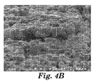
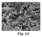
この試料は、電流コレクタとして検査され、許容可能な性能により機能的であることが見出された。類似の試料は、結果として生じるコーティングの形態を判定するために走査電子顕微鏡(SEM)を使用して撮像され、グラファイトと処理されない試料と比較した。図4a、4bは、ナノ多孔質アルミニウム電流コレクタを示す。図4bの試料は、表面の真横向き視野を可能にするために、180°で曲げることによって意図的に亀裂を入れた。このナノ多孔質電流コレクタの多孔性は、表面から内側へ少なくとも365nmまで延在することが認められる。図5a及び5bは、粉末グラファイトが、提供される方法によるナノ多孔質箔に(8秒間)研磨された後の、ナノ多孔質アルミニウム電流コレクタの画像を示す。これらのSEMは、グラファイトの適用及び研磨が、図5a及び5bに見られるように、試料のトポグラフィーを変更するように見えないことを示す。この電流コレクタ表面のナノ多孔質構造が維持される。そして、これらの試料は、電気化学キャパシタ内の電極として十分に機能する。 This sample was tested as a current collector and found to be functional with acceptable performance. Similar samples were imaged using a scanning electron microscope (SEM) to determine the resulting coating morphology and compared to graphite and untreated samples. Figures 4a and 4b show a nanoporous aluminum current collector. The sample of FIG. 4b was intentionally cracked by bending at 180 ° to allow a true lateral view of the surface. It can be seen that the porosity of this nanoporous current collector extends from the surface inward to at least 365 nm. Figures 5a and 5b show images of a nanoporous aluminum current collector after powdered graphite has been polished (8 seconds) into a nanoporous foil by the provided method. These SEMs indicate that the graphite application and polishing does not appear to alter the sample topography, as seen in FIGS. 5a and 5b. The nanoporous structure of the current collector surface is maintained. These samples sufficiently function as electrodes in the electrochemical capacitor.
実施例2
実施例と同様の方法が、異なる持続時間(8秒、15秒、及び30秒)のバフコーティングを使用してエッチングされたアルミニウムをコーティングするために使用された。試料の全てを、電流コレクタとして確実に検査した。
Example 2
A method similar to the example was used to coat the etched aluminum using buff coatings of different durations (8 seconds, 15 seconds, and 30 seconds). All of the samples were reliably inspected as current collectors.
本開示の態様による、導電性コーティングを有する電流コレクタを備える電気化学的導電性物品及びその製造方法の代表的な実施形態を以下に示す。 An exemplary embodiment of an electrochemically conductive article comprising a current collector having a conductive coating and a method for manufacturing the same according to aspects of the present disclosure is provided below.
実施形態1は、電流コレクタと、前記電流コレクタと接触する炭素コーティングと、を備え、前記炭素コーティングが結合剤を含まず、前記電流コレクタが多孔質金属を含む、導電性物品である。 Embodiment 1 is an electrically conductive article comprising a current collector and a carbon coating in contact with the current collector, wherein the carbon coating does not include a binder and the current collector includes a porous metal.
実施形態2は、前記多孔質金属が、アルミニウムを含む、実施形態1に記載の導電性物品である。 Embodiment 2 is the conductive article according to embodiment 1, wherein the porous metal includes aluminum.
実施形態3は、前記多孔質金属が、エッチングされたアルミニウムを含む、実施形態2に記載の導電性物品である。 Embodiment 3 is the conductive article according to embodiment 2, wherein the porous metal includes etched aluminum.
実施形態4は、前記炭素コーティングが、グラファイトを含む、実施形態1に記載の導電性物品である。 Embodiment 4 is the conductive article according to embodiment 1, wherein the carbon coating comprises graphite.
実施形態5は、前記物品が、電気化学キャパシタを備える、実施形態1に記載の導電性物品である。 Embodiment 5 is the conductive article according to embodiment 1, wherein the article comprises an electrochemical capacitor.
実施形態6は、前記電気化学キャパシタが、電気化学二重層キャパシタである、実施形態5に記載の導電性物品である。 Embodiment 6 is the conductive article according to embodiment 5, wherein the electrochemical capacitor is an electrochemical double layer capacitor.
実施形態7は、電流コレクタと、炭素から本質的になり、前記電流コレクタと接触しているコーティングと、を備え、前記電流コレクタが、多孔質アルミニウムを含む、導電性物品である。 Embodiment 7 is a conductive article comprising a current collector and a coating consisting essentially of carbon and in contact with the current collector, the current collector comprising porous aluminum.
実施形態8は、前記炭素が、グラファイトを含む、実施形態7に記載の導電性物品である。 Embodiment 8 is the conductive article according to embodiment 7, wherein the carbon includes graphite.
実施形態9は、前記電気化学的導電性物品が、電気化学キャパシタを備える、実施形態7に記載の導電性物品である。 Embodiment 9 is the conductive article of embodiment 7, wherein the electrochemically conductive article comprises an electrochemical capacitor.
実施形態10は、前記電気化学キャパシタが、電気化学二重層キャパシタである、実施形態9に記載の導電性物品である。
実施形態11は、第1の表面及び第2の表面を有する多孔質金属箔を提供することと、炭素粉末を前記多孔質金属箔の前記第1の表面に適用することと、前記多孔質金属箔の前記第1の表面を振動パッドで研磨することと、を含む、電極の製造方法である。 Embodiment 11 provides a porous metal foil having a first surface and a second surface, applying carbon powder to the first surface of the porous metal foil, and the porous metal Polishing the first surface of the foil with a vibration pad.
実施形態12は、前記多孔質金属箔が、アルミニウムを含む、実施形態11に記載の電極の製造方法である。
実施形態13は、前記多孔質金属が、エッチングされたアルミニウムを含む、実施形態12に記載の電極の製造方法である。
Embodiment 13 is the manufacturing method of the electrode according to
実施形態14は、前記炭素粉末が、グラファイトを含む、実施形態11に記載の電極の製造方法である。
実施形態15は、グラファイト粉末を適用することが、前記多孔質金属の前記第1の表面上に前記グラファイト粉末を散布することを含む、実施形態14に記載の電極の製造方法である。
Embodiment 15 is the method of manufacturing an electrode according to
実施形態16は、前記研磨することが、前記振動パッドを手動で前後に動かすことを含む、実施形態11に記載の電極の製造方法である。
実施形態17は、前記研磨することが、動力工具を使用することを含む、実施形態11に記載の電極の製造方法である。 Embodiment 17 is the method of manufacturing an electrode according to embodiment 11, wherein the polishing includes using a power tool.
実施形態18は、炭素粉末を前記多孔質金属箔の前記第2の表面に適用することと、前記多孔質金属箔の前記第2の表面を振動パッドで研磨することと、を更に含む、実施形態11に記載の電極の製造方法である。 Embodiment 18 further comprises applying carbon powder to the second surface of the porous metal foil and polishing the second surface of the porous metal foil with a vibration pad. It is a manufacturing method of the electrode according to Form 11.
本発明の範囲及び趣旨から逸脱しない本発明の様々な変更や改変は、当業者には明らかとなるであろう。本発明は、本明細書で述べる例示的な実施形態及び実施例によって不当に限定されるものではないこと、また、こうした実施例及び実施形態は、本明細書において以下に記述する特許請求の範囲によってのみ限定されると意図する本発明の範囲に関する例示のためにのみ提示されることを理解すべきである。本開示に引用される参照文献は全て、その全体を本明細書に援用するものである。 Various changes and modifications of this invention will become apparent to those skilled in the art without departing from the scope and spirit of this invention. The present invention is not unduly limited by the exemplary embodiments and examples described herein, and such examples and embodiments are claimed in the claims herein below. It should be understood that this is presented only for illustration regarding the scope of the invention, which is intended to be limited only by. All references cited in this disclosure are hereby incorporated by reference in their entirety.
Claims (3)
前記電流コレクタと接触するグラファイトコーティングと、を備え、
前記グラファイトコーティングが、結合剤を含まず、
前記電流コレクタが、多孔質金属を含み、
前記グラファイトコーティングが、前記多孔質金属のナノ細孔性を維持しながら前記多孔質金属のナノ多孔質構造を覆っている、導電性物品。 A current collector;
A graphite coating in contact with the current collector,
The graphite coating does not contain a binder;
Wherein the current collector is, look at including a porous metal,
The conductive article , wherein the graphite coating covers the nanoporous structure of the porous metal while maintaining the nanoporosity of the porous metal .
炭素粉末を前記多孔質金属箔の前記第1の表面に付着させるステップであって、前記炭素粉末を塗料溶媒又は結合剤が存在しない乾燥粉末として付着させるステップと、
前記炭素粉末を付着させるステップに続いて、前記多孔質金属箔の前記第1の表面を振動パッドで研磨するステップと、
前記多孔質金属箔のナノ細孔性を維持しながら前記多孔質金属箔のナノ多孔質構造を覆うグラファイトコーティングを形成するステップと、を含む、電極の製造方法。 Providing a porous metal foil having a first surface and a second surface;
Attaching carbon powder to the first surface of the porous metal foil, the carbon powder being attached as a dry powder free of paint solvent or binder;
Following the step of attaching the carbon powder, polishing the first surface of the porous metal foil with a vibration pad;
Forming a graphite coating covering the nanoporous structure of the porous metal foil while maintaining the nanoporosity of the porous metal foil .
Applications Claiming Priority (3)
| Application Number | Priority Date | Filing Date | Title |
|---|---|---|---|
| US41469710P | 2010-11-17 | 2010-11-17 | |
| US61/414,697 | 2010-11-17 | ||
| PCT/US2011/060285 WO2012067952A1 (en) | 2010-11-17 | 2011-11-11 | Electrochemically-conductive articles including current collectors having conductive coatings and methods of making same |
Publications (3)
| Publication Number | Publication Date |
|---|---|
| JP2014502046A JP2014502046A (en) | 2014-01-23 |
| JP2014502046A5 JP2014502046A5 (en) | 2014-12-04 |
| JP5859016B2 true JP5859016B2 (en) | 2016-02-10 |
Family
ID=45346545
Family Applications (1)
| Application Number | Title | Priority Date | Filing Date |
|---|---|---|---|
| JP2013539915A Expired - Fee Related JP5859016B2 (en) | 2010-11-17 | 2011-11-11 | Electrochemically conductive article comprising a current collector with a conductive coating and method for manufacturing the same |
Country Status (7)
| Country | Link |
|---|---|
| US (2) | US20130224590A1 (en) |
| EP (1) | EP2641251A1 (en) |
| JP (1) | JP5859016B2 (en) |
| KR (1) | KR101918309B1 (en) |
| CN (1) | CN103222090B (en) |
| TW (1) | TWI547963B (en) |
| WO (1) | WO2012067952A1 (en) |
Families Citing this family (26)
| Publication number | Priority date | Publication date | Assignee | Title |
|---|---|---|---|---|
| US9217198B2 (en) | 2011-07-07 | 2015-12-22 | Itn Energy Systems, Inc. | Insertion of lithium into electrochromic devices after completion |
| US9293796B2 (en) * | 2011-12-15 | 2016-03-22 | Itn Energy Systems, Inc. | Metal-air battery with dual electrode anode |
| US8980485B2 (en) | 2011-12-30 | 2015-03-17 | Itn Energy Systems, Inc. | Rechargeable, thin-film, all solid-state metal-air battery |
| US9013777B2 (en) | 2012-02-03 | 2015-04-21 | Itn Energy Systems, Inc. | Integrated device architectures for electrochromic devices |
| CN103545556B (en) * | 2012-07-13 | 2016-01-20 | 清华大学 | The preparation method of film lithium ion battery |
| CN103545555B (en) | 2012-07-13 | 2016-01-20 | 清华大学 | The preparation method of lithium ion battery |
| CN103545529B (en) | 2012-07-13 | 2016-01-20 | 清华大学 | Film lithium ion battery |
| CN103545554B (en) * | 2012-07-13 | 2016-06-08 | 清华大学 | The preparation method of lithium ion battery |
| CN103545528B (en) * | 2012-07-13 | 2016-03-09 | 清华大学 | Lithium ion battery |
| CN103545530B (en) * | 2012-07-13 | 2016-04-27 | 清华大学 | Collector, lithium ion cell electrode and lithium ion battery |
| JP6350150B2 (en) * | 2013-09-30 | 2018-07-04 | 株式会社Gsユアサ | Electricity storage element |
| CN203573823U (en) * | 2013-11-06 | 2014-04-30 | 宜春市六和电子有限公司 | Organic film winding type Y capacitor with foil-type electrodes |
| WO2015087948A1 (en) * | 2013-12-12 | 2015-06-18 | 住友電気工業株式会社 | Carbon material-coated metal porous body, collector, electrode, and power storage device |
| US10044028B1 (en) | 2014-01-29 | 2018-08-07 | Itn Energy Systems, Inc. | Composite cathode solid state battery |
| KR101693359B1 (en) * | 2014-03-31 | 2017-01-05 | (주)탑전지 | Aluminum current collector, electrode comprising the Aluminum current collector, and electrochemical device comprising the electrode |
| CN107851835A (en) * | 2015-07-27 | 2018-03-27 | 3M创新有限公司 | Graphite modified metal lithium electrode |
| WO2017190364A1 (en) * | 2016-05-06 | 2017-11-09 | 深圳先进技术研究院 | Secondary battery and preparation method therefor |
| US10636581B2 (en) | 2016-06-17 | 2020-04-28 | Tpr Co., Ltd. | Electric double layer capacitor |
| JP6766596B2 (en) * | 2016-10-31 | 2020-10-14 | トヨタ自動車株式会社 | Method for manufacturing electrodes for lithium-ion secondary batteries |
| WO2018129996A1 (en) * | 2017-01-10 | 2018-07-19 | 广东长盈精密技术有限公司 | Surface treatment method of material, material product and composite material |
| US20220328863A1 (en) * | 2018-05-22 | 2022-10-13 | Shenzhen Institutes Of Advanced Technology | Secondary battery and preparation method therefor |
| JP7488639B2 (en) | 2019-10-15 | 2024-05-22 | 本田技研工業株式会社 | Electrode for lithium ion secondary battery, and lithium ion secondary battery |
| CN111370752A (en) * | 2020-04-08 | 2020-07-03 | 隆能科技(南通)有限公司 | Fast charging and safe low temperature lithium ion battery and method of manufacturing the same |
| CN111276733A (en) * | 2020-04-21 | 2020-06-12 | 隆能科技(南通)有限公司 | Safe low-temperature lithium ion battery capable of being charged and discharged quickly and preparation method thereof |
| CN111600064A (en) * | 2020-05-13 | 2020-08-28 | 隆能科技(南通)有限公司 | Fast-charging lithium ion battery with high energy density and long service life and preparation method thereof |
| GB2614734A (en) * | 2022-01-14 | 2023-07-19 | Morrow Batteries As | Binder free carbon coated Al-foil for battery applications |
Family Cites Families (18)
| Publication number | Priority date | Publication date | Assignee | Title |
|---|---|---|---|---|
| US3369268A (en) | 1967-06-02 | 1968-02-20 | Painter Corp E Z | Paint applying tool |
| US5578396A (en) * | 1994-10-19 | 1996-11-26 | Arthur D. Little, Inc. | Current collector device |
| US5588971A (en) | 1994-10-19 | 1996-12-31 | Arthur D. Little, Inc. | Current collector device and method of manufacturing same |
| US6195251B1 (en) * | 1997-10-29 | 2001-02-27 | Asahi Glass Company Ltd. | Electrode assembly and electric double layer capacitor having the electrode assembly |
| JPH11283608A (en) * | 1998-03-26 | 1999-10-15 | Tdk Corp | Electrode for battery, manufacture thereof and battery |
| US6442015B1 (en) * | 1999-01-07 | 2002-08-27 | Ngk Insulators, Ltd. | Electrochemical capacitors |
| JP2000286167A (en) * | 1999-03-29 | 2000-10-13 | Toyota Motor Corp | Manufacture of electrode for battery and capacitor |
| US6511701B1 (en) | 2000-05-09 | 2003-01-28 | 3M Innovative Properties Company | Coatings and methods |
| US7388740B2 (en) * | 2003-03-31 | 2008-06-17 | Toyo Aluminium Kabushiki Kaisha | Foil for negative electrode of capacitor and process for producing the same |
| JP2005191423A (en) | 2003-12-26 | 2005-07-14 | Tdk Corp | Electrode for capacitor |
| JP4972854B2 (en) * | 2004-06-18 | 2012-07-11 | 株式会社Ihi | Electrode and electrode manufacturing method |
| JP2006024726A (en) * | 2004-07-08 | 2006-01-26 | Tdk Corp | Electrochemical element and its manufacturing process |
| JP4670430B2 (en) * | 2005-03-30 | 2011-04-13 | Tdk株式会社 | Electrochemical devices |
| US20070258192A1 (en) * | 2006-05-05 | 2007-11-08 | Joel Schindall | Engineered structure for charge storage and method of making |
| US20090130564A1 (en) * | 2007-11-19 | 2009-05-21 | Enerize Corporation | Method of fabrication electrodes with low contact resistance for batteries and double layer capacitors |
| US20090180238A1 (en) * | 2008-01-11 | 2009-07-16 | Maxwell Technologies, Inc. | Energy storage devices |
| US8178241B2 (en) * | 2008-08-28 | 2012-05-15 | 3M Innovative Properties Company | Electrode including current collector with nano-scale coating and method of making the same |
| EP2306475A1 (en) * | 2008-10-10 | 2011-04-06 | Panasonic Corporation | Electrode foil for capacitor, manufacturing method therefor, and solid electrolytic capacitor using the electrode foil |
-
2011
- 2011-11-11 CN CN201180055303.8A patent/CN103222090B/en not_active Expired - Fee Related
- 2011-11-11 EP EP11794883.6A patent/EP2641251A1/en not_active Withdrawn
- 2011-11-11 JP JP2013539915A patent/JP5859016B2/en not_active Expired - Fee Related
- 2011-11-11 KR KR1020137015058A patent/KR101918309B1/en active IP Right Grant
- 2011-11-11 WO PCT/US2011/060285 patent/WO2012067952A1/en active Application Filing
- 2011-11-11 US US13/884,329 patent/US20130224590A1/en not_active Abandoned
- 2011-11-16 TW TW100141871A patent/TWI547963B/en not_active IP Right Cessation
-
2017
- 2017-09-13 US US15/703,240 patent/US20180005767A1/en not_active Abandoned
Also Published As
| Publication number | Publication date |
|---|---|
| TW201227769A (en) | 2012-07-01 |
| WO2012067952A1 (en) | 2012-05-24 |
| KR20130112906A (en) | 2013-10-14 |
| TWI547963B (en) | 2016-09-01 |
| CN103222090A (en) | 2013-07-24 |
| EP2641251A1 (en) | 2013-09-25 |
| KR101918309B1 (en) | 2018-11-13 |
| CN103222090B (en) | 2016-06-08 |
| US20130224590A1 (en) | 2013-08-29 |
| US20180005767A1 (en) | 2018-01-04 |
| JP2014502046A (en) | 2014-01-23 |
Similar Documents
| Publication | Publication Date | Title |
|---|---|---|
| JP5859016B2 (en) | Electrochemically conductive article comprising a current collector with a conductive coating and method for manufacturing the same | |
| US9172085B2 (en) | Electrode including current collector with nano-scale coating and method of making the same | |
| JP2023087098A (en) | Porous interconnected wavy carbon-based network (iccn) composite material | |
| KR101995465B1 (en) | Electrode structure having roll shape, electrode and electric device including the electrode structure, and method of manufacturing the electrode structure | |
| US20170263939A1 (en) | Electrode material and energy storage apparatus | |
| EP2564404B1 (en) | Method for preparing a carbon composite electrode for electric double-layer capacitor | |
| CN102918613A (en) | A multi-element electrochemical capacitor and a method for manufacturing the same | |
| KR20060119817A (en) | Method for producing electrochemical capacitor electrode | |
| JP5269390B2 (en) | Electrode film, electrode, manufacturing method thereof, and electric double layer capacitor | |
| EP4184605A1 (en) | Method for lead carbon compression moulding and applications thereof | |
| KR101940795B1 (en) | Electrode structure having roll shape, electrode and electric device including the electrode structure, and method of manufacturing the electrode structure | |
| WO2003103076A1 (en) | Conductive material-mixed electrode active material, electrode structure, secondary cell, amd method for producing conductive material-mixed electrode active material | |
| WO2017160897A1 (en) | Separators for high density electrochemical energy storage | |
| JP2000286167A (en) | Manufacture of electrode for battery and capacitor | |
| Rai et al. | Analysis of Supercapacitor based on Carbon-Graphite-Metal oxide composition |
Legal Events
| Date | Code | Title | Description |
|---|---|---|---|
| A521 | Written amendment |
Free format text: JAPANESE INTERMEDIATE CODE: A523 Effective date: 20141016 |
|
| A621 | Written request for application examination |
Free format text: JAPANESE INTERMEDIATE CODE: A621 Effective date: 20141016 |
|
| A977 | Report on retrieval |
Free format text: JAPANESE INTERMEDIATE CODE: A971007 Effective date: 20150811 |
|
| A131 | Notification of reasons for refusal |
Free format text: JAPANESE INTERMEDIATE CODE: A131 Effective date: 20150818 |
|
| A521 | Written amendment |
Free format text: JAPANESE INTERMEDIATE CODE: A523 Effective date: 20151102 |
|
| TRDD | Decision of grant or rejection written | ||
| A01 | Written decision to grant a patent or to grant a registration (utility model) |
Free format text: JAPANESE INTERMEDIATE CODE: A01 Effective date: 20151201 |
|
| A61 | First payment of annual fees (during grant procedure) |
Free format text: JAPANESE INTERMEDIATE CODE: A61 Effective date: 20151215 |
|
| R150 | Certificate of patent or registration of utility model |
Ref document number: 5859016 Country of ref document: JP Free format text: JAPANESE INTERMEDIATE CODE: R150 |
|
| R250 | Receipt of annual fees |
Free format text: JAPANESE INTERMEDIATE CODE: R250 |
|
| LAPS | Cancellation because of no payment of annual fees |