JP5857504B2 - Position calculation method and imaging apparatus - Google Patents
Position calculation method and imaging apparatus Download PDFInfo
- Publication number
- JP5857504B2 JP5857504B2 JP2011168069A JP2011168069A JP5857504B2 JP 5857504 B2 JP5857504 B2 JP 5857504B2 JP 2011168069 A JP2011168069 A JP 2011168069A JP 2011168069 A JP2011168069 A JP 2011168069A JP 5857504 B2 JP5857504 B2 JP 5857504B2
- Authority
- JP
- Japan
- Prior art keywords
- time
- unit
- camera shake
- sensor data
- absolute position
- Prior art date
- Legal status (The legal status is an assumption and is not a legal conclusion. Google has not performed a legal analysis and makes no representation as to the accuracy of the status listed.)
- Expired - Fee Related
Links
- 238000004364 calculation method Methods 0.000 title claims description 69
- 238000003384 imaging method Methods 0.000 title claims description 40
- 238000001514 detection method Methods 0.000 claims description 46
- 230000001133 acceleration Effects 0.000 claims description 13
- 239000013598 vector Substances 0.000 description 67
- 238000000034 method Methods 0.000 description 43
- 230000008569 process Effects 0.000 description 34
- 238000013500 data storage Methods 0.000 description 17
- 230000006870 function Effects 0.000 description 10
- 238000010586 diagram Methods 0.000 description 8
- 238000005259 measurement Methods 0.000 description 6
- 230000008859 change Effects 0.000 description 2
- 230000004913 activation Effects 0.000 description 1
- 230000008901 benefit Effects 0.000 description 1
- 230000001747 exhibiting effect Effects 0.000 description 1
- 238000000605 extraction Methods 0.000 description 1
- 230000010354 integration Effects 0.000 description 1
- 239000004973 liquid crystal related substance Substances 0.000 description 1
- 230000003287 optical effect Effects 0.000 description 1
- 239000007787 solid Substances 0.000 description 1
Images
Landscapes
- Position Fixing By Use Of Radio Waves (AREA)
- Studio Devices (AREA)
Description
本発明は、位置算出方法に関する。 The present invention relates to a position calculation method.
測位用信号を利用した測位システムとしては、GPS(Global Positioning System)が広く知られており、携帯型電話機やカーナビゲーション装置等に内蔵された位置算出装置に利用されている。GPSでは、複数のGPS衛星の位置や各GPS衛星から位置算出装置までの擬似距離等の情報に基づいて位置算出装置の位置座標と時計誤差とを求める位置算出計算を行う。 A GPS (Global Positioning System) is widely known as a positioning system using positioning signals, and is used in a position calculation device built in a mobile phone or a car navigation device. In the GPS, position calculation calculation for obtaining position coordinates and clock error of the position calculation device is performed based on information such as positions of a plurality of GPS satellites and pseudo distances from each GPS satellite to the position calculation device.
位置算出装置は、携帯型電話機やカーナビゲーション装置といった電子機器の他にも、種々の電子機器に内蔵されて利用されている。例えば、位置算出装置を搭載したデジタルカメラにおいて、撮影画像のデータと位置情報のデータとを対応付けて記録する技術が考案されている(例えば、特許文献1参照)。 In addition to electronic devices such as mobile phones and car navigation devices, the position calculation device is used by being incorporated in various electronic devices. For example, in a digital camera equipped with a position calculation device, a technique has been devised in which captured image data and position information data are recorded in association with each other (see, for example, Patent Document 1).
GPSを利用して位置算出計算を行うためには、GPS衛星の衛星軌道データが必要となる。しかし、衛星軌道データを保持していない状態で測位を開始する、いわゆるコールドスタート等の状態では、GPS衛星から衛星軌道データを取得するために一定の時間が必要となる。一方で、上述したデジタルカメラを例に挙げると、撮影は短時間で終了する。そのため、撮影時刻に位置算出を完結させることには時間的な問題がある。他の電子機器についても同様に考えると、所与の希望時刻に位置算出を完結させることには時間的な問題があると言える。 In order to perform position calculation calculation using GPS, satellite orbit data of GPS satellites is required. However, in a state such as a so-called cold start in which positioning is started without holding satellite orbit data, a certain time is required to acquire satellite orbit data from a GPS satellite. On the other hand, taking the digital camera described above as an example, shooting is completed in a short time. Therefore, there is a time problem in completing the position calculation at the photographing time. Considering other electronic devices in the same way, it can be said that there is a time problem in completing position calculation at a given desired time.
本発明は上述した課題に鑑みて為されたものであり、その目的とするところは、後刻において、過去の希望時刻における位置算出を可能とする技術を提供することにある。 The present invention has been made in view of the above-described problems, and an object of the present invention is to provide a technique that enables position calculation at a past desired time later.
本発明は、上述の課題の少なくとも一部を解決するためになされたものであり、以下の形態又は適用例として実現することが可能である。 SUMMARY An advantage of some aspects of the invention is to solve at least a part of the problems described above, and the invention can be implemented as the following forms or application examples.
[適用例1]本適用例に係る位置算出方法は、衛星からの信号を受信して現在位置を算出する測位機能を有する撮像装置の位置算出方法であって、前記撮像装置の撮像部の手ぶれ振動を検出することと、現在時刻を保持することと、前記撮像装置の少なくとも加速度情報を含むセンサーデータを計測することと、前記検出した手ぶれ振動が所定の状態であるか判断することと、前記検出した手ぶれ振動が所定の状態であると判断したときに、前記現在時刻と前記センサーデータとを対応付けて保存し、かつ前記衛星からの信号に基づいて測位した前記撮像装置の絶対位置及び前記センサーデータを使って前記撮像装置の位置を算出することと、を含むことを特徴とする。 [Application Example 1] A position calculation method according to this application example is a position calculation method of an imaging apparatus having a positioning function that receives a signal from a satellite and calculates a current position, and is a camera shake of an imaging unit of the imaging apparatus. Detecting vibration, holding a current time, measuring sensor data including at least acceleration information of the imaging device, determining whether the detected camera shake vibration is in a predetermined state, When it is determined that the detected camera shake is in a predetermined state, the current time and the sensor data are stored in association with each other, and the absolute position of the imaging device measured based on a signal from the satellite and the Calculating the position of the imaging device using sensor data.
本適用例によれば、手ぶれ検出の検出状態が所定値を超えると、それ以降のデータを撮影位置を計算するために使用するセンサーデータと認識し、センサーデータが出力された時刻と関連づけて保存する。その後絶対位置検出部で絶対位置を検出する。そして、前記センサーデータと絶対位置とを使って、撮影位置を算出する。こうすることで、後刻においても正確な撮影位置を把握することができる。 According to this application example, when the detection state of camera shake detection exceeds a predetermined value, the subsequent data is recognized as sensor data used for calculating the shooting position, and stored in association with the time when the sensor data is output. To do. Thereafter, an absolute position is detected by an absolute position detector. Then, the shooting position is calculated using the sensor data and the absolute position. By doing so, an accurate shooting position can be grasped even at a later time.
[適用例2]上記適用例に記載の位置算出方法において、前記撮像装置の位置を算出することは、前記検出した手ぶれ振動が所定の状態であると判断した時点以降に撮影を実行した時刻を起点時刻として、前記絶対位置と前記センサーデータとを使って前記起点時刻における撮像装置の位置を算出することを特徴とする。 Application Example 2 In the position calculation method described in the above application example, calculating the position of the imaging device is based on a time when shooting is performed after it is determined that the detected camera shake vibration is in a predetermined state. As the starting time, the position of the imaging device at the starting time is calculated using the absolute position and the sensor data.
本適用例によれば、手ぶれ検出状態が所定値を超えた時刻以降に撮影が実行された時刻を起点時刻として位置算出を行うので、撮像時の位置取得のために記憶するセンサーデータを最小限にすることができる。 According to this application example, since the position calculation is performed with the time when the shooting is performed after the time when the camera shake detection state exceeds the predetermined value as the starting time, the sensor data stored for acquiring the position at the time of imaging is minimized. Can be.
[適用例3]上記適用例に記載の位置算出方法において、前記絶対位置と前記センサーデータとを使って前記起点時刻における撮像装置の位置を算出することは、前記センサーデータを用いて移動方向及び移動距離を含む移動情報を算出し、前記絶対位置と前記移動情報を使って前記起点時刻における前記撮像装置の位置を算出することを特徴とする。 Application Example 3 In the position calculation method according to the application example described above, calculating the position of the imaging device at the starting time using the absolute position and the sensor data includes using the sensor data and a moving direction and Movement information including a movement distance is calculated, and the position of the imaging device at the starting time is calculated using the absolute position and the movement information.
本適用例によれば、センサーデータを用いて絶対位置が検出されるまでの移動方向及び移動距離でなる移動情報を算出できるので、後刻に取得した絶対位置からと移動情報を使って時間をさかのぼって起点時刻における位置を算出することができる。 According to this application example, since the movement information including the movement direction and the movement distance until the absolute position is detected can be calculated using the sensor data, the time can be traced back using the movement information from the absolute position acquired later. Thus, the position at the starting time can be calculated.
[適用例4]上記適用例に記載の位置算出方法において、前記手ぶれ振動の所定の状態とは、単位時間あたりの手ぶれ補正信号検出回数が所定の回数以上であることを特徴とする。 Application Example 4 In the position calculation method according to the application example described above, the predetermined state of camera shake vibration is characterized in that the number of camera shake correction signal detections per unit time is equal to or greater than a predetermined number.
本適用例によれば、センサーデータを保存開始するためのタイミングを容易に把握することができる。 According to this application example, it is possible to easily grasp the timing for starting storage of sensor data.
[適用例5]上記適用例に記載の位置算出方法において、前記手ぶれ検出の検出状態は、少なくとも前記手ぶれ検出の時間間隔又は単位時間あたりの検出回数のいずれかを含むことを含むことを特徴とする。 Application Example 5 In the position calculation method according to the application example described above, the detection state of the camera shake detection includes at least one of the time interval of the camera shake detection or the number of detections per unit time. To do.
本適用例によれば、センサーデータを保存開始するためのタイミングを容易に把握することができる。 According to this application example, it is possible to easily grasp the timing for starting storage of sensor data.
[適用例6]上記適用例に記載の位置算出方法において、前記絶対位置の測位は、前記撮像部の電源供給量が所定条件以下になった場合に開始することを特徴とする。 Application Example 6 In the position calculation method according to the application example described above, the positioning of the absolute position is started when the power supply amount of the imaging unit becomes a predetermined condition or less.
本適用例によれば、絶対位置を検出する際の撮像部からのノイズを低減することができ、より正確な絶対位置を検出することができる。 According to this application example, it is possible to reduce noise from the imaging unit when detecting the absolute position, and it is possible to detect a more accurate absolute position.
以下、図面を参照して、電子機器の一種であるデジタルカメラの位置算出を行うシステムである位置算出システムの実施形態について説明する。但し、本発明を適用可能な実施形態が以下説明する実施形態に限定されるわけでないことは勿論である。 Hereinafter, an embodiment of a position calculation system which is a system for calculating the position of a digital camera which is a kind of electronic apparatus will be described with reference to the drawings. However, it goes without saying that embodiments to which the present invention can be applied are not limited to the embodiments described below.
1.機能構成
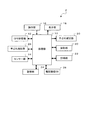
図1は、本実施形態に係るデジタルカメラの機能構成の一例を示すブロック図である。本実施形態に係わるデジタルカメラ2は、処理部10と、GPS受信部12と、センサー部14と、操作部16と、表示部18と、撮像部20と、計時部22と、記憶部24と、撮影画像DB26と、手ぶれ検出部28と、手ぶれ補正部30とを備えて構成される。
1. Functional Configuration FIG. 1 is a block diagram illustrating an example of a functional configuration of a digital camera according to the present embodiment. The
処理部10は、記憶部24に記憶されているシステムプログラム等の各種プログラムに従ってデジタルカメラの各部を統括的に制御する制御装置であり、CPU(Central Processing Unit)等のプロセッサーを有して構成される。処理部10は、デジタルカメラ2の本質的な機能を実現するために、操作部16を介して入力された指示操作に従って、デジタルカメラ2の正面方向の画像を撮像部20に撮影させる撮影処理を実行したり、撮影された画像を表示部18に表示させたりする処理を行う。また手ぶれ検出部28からの信号を元に手ぶれ状態の検知や手ぶれ補正量を決定し、手ぶれ補正部30による手ぶれ補正処理の実行指示なども行う。
The
また、処理部10は、デジタルカメラ2に位置算出機能を実現させるために、次のような処理を行う。すなわち、手ぶれ検出部28からの信号を元に、センサー部14のデータと計時部22の時刻とを関連づけた有効センサーデータの記憶部24への保存を開始する(第1処理)。次にデジタルカメラ2によって撮影処理を実行した時刻(希望時刻)を記憶部24に保存する。その後、撮像部20への電源供給量が所定値以下になると、GPS受信部12を起動させ、取得された絶対位置を取得時刻と対応付けて記憶部24に記憶させる処理を実行する(第2処理)。そして、センサー部14の検出結果を用いてデジタルカメラ2の移動方向及び移動距離を示す移動ベクトルを算出し、算出した移動ベクトルと取得した絶対位置とを用いて、希望時刻におけるデジタルカメラ2の位置を算出する処理を行う。
Further, the
手ぶれ検出部28は撮影者の手ぶれによる振動量(以下、手ぶれ量)を検出する。検出方式には、手ぶれによる撮像部(装置自体)20の振動をセンサーによって検出する方式(以下、センサー方式)と、撮影した画像に基づいて手ぶれ量を検出する方式(以下、動きベクトル方式)とがある。
The camera
センサー方式では、コリオリの力を応用した角速度センサーなどの検出器を装置に組み込んで、手ぶれによる撮像部(装置自体)20の振動量を検出することにより、デジタルカメラ2の手ぶれによる動きがリアルタイムに検出されるので、手ぶれ量を検出するときに被写体の状況(被写体の種類、明るさ、動き) に影響されないという特徴がある。 In the sensor system, a detector such as an angular velocity sensor using Coriolis force is incorporated in the device, and the amount of vibration of the image pickup unit (device itself) 20 due to camera shake is detected. Therefore, when detecting the amount of camera shake, there is a feature that it is not affected by the state of the subject (type of subject, brightness, movement).
一方、動きベクトル方式は、撮像レンズを介して投影される被写体の画像(光の信号)を撮像素子で検出し、画像信号としてメモリーに記憶しておき、次に検出する画像信号と比較して画像のぶれを動きベクトルデータとして検出する。つまり、直近の2つの画像信号の違いを動きベクトルデータとして検出するので、手ぶれ量を検出するときに撮影倍率の変化などの光学系の状態に影響を受けないという特徴がある。 On the other hand, in the motion vector method, an image of a subject (light signal) projected through an imaging lens is detected by an imaging device, stored as an image signal in a memory, and compared with an image signal to be detected next. Image blur is detected as motion vector data. That is, since the difference between the two most recent image signals is detected as motion vector data, there is a feature that when detecting the amount of camera shake, it is not affected by the state of the optical system such as a change in photographing magnification.
本実施形態において、手ぶれ検出方法はどちらの方式を採用しても良い。またこれらを組み合わせて手ぶれを検出する方法でも良い。 In the present embodiment, either method may be adopted as the camera shake detection method. A combination of these methods may be used to detect camera shake.
手ぶれ検出部28は手ぶれを検出すると、手ぶれ信号として検出した手ぶれ量を処理部10へ伝送する。処理部10は手ぶれ信号を元に補正量を決定し、手ぶれ補正部30に補正を実行させる。処理部10では、手ぶれ信号を受信して補正量を決定する動作を所定以上の頻度で実施した場合に、有効センサーデータを記憶部24に保存する処理を行う。
When the camera
GPS受信部12は、不図示のGPSアンテナにより受信されたGPS衛星信号に基づいてデジタルカメラ2の位置を計測する位置算出回路或いは位置算出装置であり、いわゆるGPS受信機に相当する機能ブロックである。図示を省略するが、GPS位置算出部は、RF受信回路部と、ベースバンド処理回路部とを備えて構成される。なお、RF受信回路部と、ベースバンド処理回路部とは、それぞれ別のLSI(Large Scale Integration)として製造することも、1チップとして製造することも可能である。
The
GPS受信部12は、受信信号からGPS衛星信号を捕捉して絶対位置情報を取得する図示しない絶対位置取得部を機能部として有している。絶対位置取得部は、受信したGPS衛星信号の拡散符号である受信CAコードと、装置内部で発生させた擬似的なCAコードであるレプリカCAコードとの相関演算を行ってGPS衛星信号を捕捉する。この際、GPS衛星信号の受信周波数を特定するためにサーチ周波数を変化させながら、受信CAコードとレプリカCAコードとの相関演算を行う。
The
また、GPS受信部12は、受信CAコードに乗算するレプリカCAコードの位相(コード位相)を変化させながら相関演算を行う。絶対位置取得部は、相関演算により計算される相関値が最大となる受信周波数及びコード位相を検出し、これらを信号の測定結果、つまりメジャメント情報として処理部10に出力する。メジャメント情報のうち、受信周波数は、主としてGPS衛星信号の捕捉やデジタルカメラ2の速度算出計算に用いられる。また、コード位相は、主としてデジタルカメラ2の位置算出計算に用いられる。
In addition, the
センサー部14は、デジタルカメラ2の移動状態を検出するためのセンサーで構成される回路部であり、例えば、加速度センサーと、ジャイロセンサーと、方位センサーとを有して構成される。
The
加速度センサーは、デジタルカメラ2の加速度を検出するセンサーであり、歪みゲージ式や圧電式のいずれであってもよく、またMEMS(Micro Electro Mechanical Systems)センサーであってもよい。また、ジャイロセンサーは、デジタルカメラ2の角速度を検出するセンサーであり、加速度センサーと軸方向が同一となるように配置設定されている。
The acceleration sensor is a sensor that detects the acceleration of the
加速度センサー及びジャイロセンサーは、予めセンサーに対応付けて定められたローカルな座標系であるセンサー座標系の直交3軸、それぞれの軸方向の加速度及び各軸の軸周りの角速度を検出して出力するように設計されている。なお、加速度センサー及びジャイロセンサーは、それぞれが独立したセンサーであってもよいし、一体型のセンサーであってもよい。 The acceleration sensor and the gyro sensor detect and output the three orthogonal axes of the sensor coordinate system, which is a local coordinate system determined in advance in association with the sensor, the acceleration in each axial direction, and the angular velocity around the axis of each axis. Designed to be The acceleration sensor and the gyro sensor may be independent sensors or may be integrated sensors.
方位センサーは、デジタルカメラ2の移動方向を検出するセンサーであり、例えば地磁気センサーを有して構成される。地磁気センサーは、いわゆる電子コンパスであり、地磁気を検知することにより北の方位を検出可能に構成されたセンサーである。
The azimuth sensor is a sensor that detects the moving direction of the
操作部16は、例えばタッチパネルやボタンスイッチ等により構成される入力装置であり、押下されたキーやボタンの信号を処理部10に出力する。この操作部16の操作により、撮影指示操作や撮影画像閲覧指示操作、撮影場所解析指示操作等の各種指示操作がなされる。
The
表示部18は、LCD(Liquid Crystal Display)等により構成され、処理部10から入力される表示信号に基づいた各種表示を行う表示装置である。表示部18には、ファインダー画像や撮影画像等が表示される。
The
撮像部20は、処理部10からの指示信号に従って、デジタルカメラ2の正面方向(レンズが向けられている方向)の画像を撮像する回路部であり、CCD(Charge Coupled Device)イメージセンサー等の撮像素子を有して構成される。
The
計時部22は、デジタルカメラ2の内部時計であり、計時時刻を処理部10に出力する。計時誤差の存在により、計時部22の計時時刻は時間経過に伴って正確な時刻からずれる。そのため、位置算出計算により算出された計時誤差を用いて、計時部22の計時誤差が較正され、正確な時刻を計時するように調整される。処理部10は、計時部22の計時時刻に基づいて、絶対位置情報の取得時刻や移動ベクトルの算出時刻、撮影時刻といった時刻を判定する。
The
記憶部24は、ROM(Read Only Memory)やフラッシュROM、RAM(Random Access Memory)等の記憶装置によって構成され、デジタルカメラ2のシステムプログラムや、撮影機能、撮影画像表示機能、撮影場所解析機能等の各種機能を実現するための各種プログラム、データ等を記憶している。また、各種処理の処理中データ、処理結果などを一時的に記憶するワークエリアを有する。
The
撮影画像DB(Data Base)26は、処理部10が撮影処理を実行することで撮影した画像が蓄積的に記憶されるデータベースである。
The photographed image DB (Data Base) 26 is a database in which images photographed by the
2.データ構成
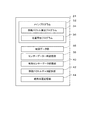
図2は、本実施形態に係る記憶部24に格納されたデータの一例を示す図である。記憶部24には、処理部10により読み出され、メイン処理として実行されるメインプログラム32が記憶されている。メインプログラム32には、移動ベクトル算出処理(図5参照)として実行される移動ベクトル算出プログラム34と、撮影位置算出処理(図6参照)として実行される位置算出プログラム36とがサブルーチンとして含まれている。
2. Data Configuration FIG. 2 is a diagram illustrating an example of data stored in the
また、メイン処理には、処理部10が、撮影機能や撮影画像表示機能等といったデジタルカメラ2としての本質的な機能を発揮するための処理の他、撮影位置算出処理により算出した位置に基づいて撮影場所を解析する処理が含まれる。撮影場所の解析を行った後は、処理部10は、解析した撮影場所等の情報を撮影画像と対応付けて撮影画像DB26に記憶させ、撮影画像表示処理において、撮影場所等の情報も併せて表示させる。
Further, in the main process, the
移動ベクトル算出処理とは、処理部10が、有効センサーデータを用いてデジタルカメラ2の移動方向及び移動距離を示す移動ベクトルを算出して記憶部24に記憶させる処理である。
The movement vector calculation process is a process in which the
撮影位置算出処理とは、処理部10が、記憶部24に記憶されている絶対位置情報と移動ベクトルとを用いて、希望時刻におけるデジタルカメラ2の位置を算出する処理である。
The shooting position calculation process is a process in which the
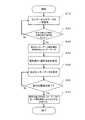
次いで、図3を参照して本実施形態における全体的な処理の流れについて説明する。
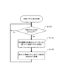
図3は、本実施形態に係る全体的な処理の流れを示すフローチャートである。まず、ステップS10において定常的に稼動しているセンサー部14から出力されるセンサーデータを記憶部24に保存する。このデータは撮影位置の算出には必要のないデータのため、一時的に記憶部24に保存される。
Next, an overall processing flow in the present embodiment will be described with reference to FIG.
FIG. 3 is a flowchart showing the overall processing flow according to the present embodiment. First, in step S <b> 10, sensor data output from the
次に、処理部10が手ぶれ検出部28からの手ぶれ信号を受信し、ステップS20において手ぶれ信号の検出状態が所定条件を超えたか否かを判断する。超えていると判断した場合(ステップS20(Yes))は、それ以降のセンサーデータを有効センサーデータとして、ステップS20において当該時刻と関連づけて記憶部24に保存する。手ぶれ信号の検出状態が所定条件以下であった場合(ステップS20(No))には、ステップS10において引き続きセンサーデータの一時保存を行う。
Next, the
次に、ステップS40において撮影者により撮影動作が実行されたら、その時刻を撮影時刻と判断し記憶する。次に、ステップS50において有効センサーデータを保存する。ステップS60において撮影後、GPS受信部12の絶対位置取得部により絶対位置が検出されたか否かを判断する。絶対位置が検出されていると判断した場合(ステップS60(Yes))は、ステップS70において絶対位置と有効センサーデータを使って撮影時刻における位置を決定する。絶対位置が未検出の場合(ステップS60(No))は、ステップS50において有効センサーデータの取得を継続する。
Next, when a photographing operation is executed by the photographer in step S40, the time is determined as the photographing time and stored. Next, effective sensor data is stored in step S50. After shooting in step S60, it is determined whether or not the absolute position is detected by the absolute position acquisition unit of the
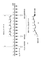
図4を参照して、本実施形態における撮影位置算出処理について説明する。
図4は、本実施形態に係る時刻と移動ベクトルとの概念図であり、図4(A)は、各種の時刻と移動ベクトルとを模式的に示した図であり、横軸は時間を示している。図4(B)は位置算出の説明図である。時間軸のt-6,t-5,・・・,t0、・・・,t9はセンサーデータ出力時刻を、点線上向き矢印はセンサーから定期的に出力されるセンサーデータを、実線上向き矢印は有効センサーデータを、手ぶれ判定時刻は処理部10で手ぶれ状況を判定した時刻を、撮影時刻はデジタルカメラ2によって撮影処理を実行した時刻を、絶対位置取得時刻は絶対位置を取得した時刻をそれぞれ示している。手ぶれ判定時刻から絶対位置取得時刻までの間にセンサーから出力されるデータを有効センサーデータとし、特に撮影時刻から絶対位置取得時刻の間のセンサーデータを移動ベクトル算出用データとする。また、時間軸の上に示した実線の矢印は、その向き及び長さによって当該算出時刻において算出された移動ベクトルを示しており、当該算出時刻から次の算出時刻までの移動状態を示すベクトルとして図示している。
With reference to FIG. 4, the shooting position calculation processing in the present embodiment will be described.
FIG. 4 is a conceptual diagram of the time and movement vector according to the present embodiment, FIG. 4A is a diagram schematically showing various times and movement vectors, and the horizontal axis indicates time. ing. FIG. 4B is an explanatory diagram of position calculation. T -6 , t -5 , ..., t 0 , ..., t 9 on the time axis indicate sensor data output time, the dotted upward arrow indicates sensor data periodically output from the sensor, and the solid upward arrow Is the effective sensor data, the camera shake determination time is the time when the camera shake situation is determined by the
まず、手ぶれ判定時刻を決定する。手ぶれ判定時刻とは、手ぶれ検出部28から処理部10に送られる手ぶれ信号が所定条件を超えたときの時刻である。所定条件とは、例えば手ぶれ信号検出の頻度や時間的間隔、又は手ぶれ信号の大きさなどである。図4ではt-4とt-3との間で所定条件を超えたため、処理部10により「t-3」は手振れ判定時刻と判定される。手ぶれ判定時刻「t-3」以前のセンサーデータは図2のセンサーデータ一時記憶部38へ保存をされており、蓄積データ量に応じて順次古いデータは自動的に破棄される(t-6からt-4)。一方、手ぶれ判定時刻「t-3」以降のセンサーデータは、有効センサーデータとして有効センサーデータ記憶部40に保存される(t-2からt7)。有効センサーデータは絶対位置取得が完了するまで、又はメモリー領域の制限やユーザーからの指示があるまで、データは破棄されない。
First, the camera shake determination time is determined. The camera shake determination time is a time when a camera shake signal sent from the camera
本実施形態ではセンサー部14からは常にデータが出力されていると想定している。実施形態によっては断続的にセンサーが起動するように制御することも可能である。また、センサーデータ一時記憶部38や有効センサーデータ記憶部40など、保存するデータの用途毎にブロックを分けて説明しているが、同一のメモリー内で保存し、データフラグを立てることでデータ種を識別できるようにしても良い。
In the present embodiment, it is assumed that data is always output from the
次に、撮影処理が時刻「t0」において実行されたものとする。すなわち、撮影時刻(希望時刻)は「t0」である。撮影時刻「t0」以降のデータは特に移動ベクトル算出用データとして後述の移動ベクトル算出プログラム34で使用される。撮影時刻「t0」の次のセンサーデータ取得時刻「t1」における有効センサーデータを取得したら、「t0」と「t1」とのデータから移動ベクトル「a」を算出する。移動ベクトル「a」はその長さ、方向により「t0」を起点とした相対的な移動情報を示す。算出された移動ベクトル「a」は図2の移動ベクトルデータ記憶部42に時刻「t0」と対応付けて保存される。時刻「t2」における有効センサーデータを取得すると、「t1」と「t2」との有効センサーデータから移動ベクトル「b」を算出する。そして時刻「t1」と移動ベクトル「b」とを対応付けて、移動ベクトルデータ記憶部42に保存される。上記動作がGPS受信部12の図示しない絶対位置取得部により絶対位置が取得されるまで繰り返し実行される。
Next, it is assumed that the photographing process is executed at time “t 0 ”. That is, the photographing time (desired time) is “t 0 ”. The data after the photographing time “t 0 ” is used in a later-described movement
次いで、絶対位置取得部により絶対位置が検出された時刻を絶対位置取得時刻「t7」として保存される。絶対位置検出時刻「t7」までのセンサーデータを有効センサーデータとしてデータ保存し、それ以降のセンサーデータ「t8」「t9」は通常のセンサーデータとしてセンサーデータ一時記憶部38に保存される。仮に時刻「t7」「t8」の間で絶対位置が取得された場合は、どちらか近い方の時刻を絶対位置取得時刻と見なし、それに対応するセンサーデータまでを有効センサーデータとして保存する。
Next, the time when the absolute position is detected by the absolute position acquisition unit is stored as the absolute position acquisition time “t 7 ”. The sensor data up to the absolute position detection time “t 7 ” is stored as valid sensor data, and the subsequent sensor data “t 8 ” and “t 9 ” are stored in the sensor data
絶対位置取得部は手ぶれ判定時刻以降の任意のタイミングで起動して、絶対位置を測定することができる。デジタルカメラ2など動作中のデバイス内ノイズが大きい用途においては、他の機能ブロックが停止している状態、又はスタンバイ状態であるときに絶対位置取得部を起動し、絶対位置検出を行うことが、より安定した検出を助けるために望ましい。
The absolute position acquisition unit can be activated at any timing after the camera shake determination time to measure the absolute position. In applications where the noise in the device during operation such as the
ここで、本実施形態では手ぶれ検出時刻を起点として有効センサーデータの保存開始、絶対位置取得部の起動を実施しているが、これは手ぶれ検出時刻を撮影者が位置情報を要求したタイミングであると判断しているためである。例えば、手ぶれ検出頻度をもって手ぶれ検出時刻を決定する場合、撮影者がデジタルカメラ2を構えているときには小さな手ぶれ振動が短い周期で観測される傾向がある。これはデジタルカメラ2が動かないように両腕に力を入れてデジタルカメラ2を支えているために生じる現象である。したがって、処理部10は手ぶれ検出部28からの手ぶれ信号を解析して、手ぶれ信号の発生頻度と強度が所定条件を満たした場合、撮影者がデジタルカメラ2で撮影する意思を持ったと判断する。
In this embodiment, effective sensor data is started to be stored and the absolute position acquisition unit is started from the camera shake detection time as a starting point. This is the timing at which the photographer requests the position information for the camera shake detection time. This is because it is judged. For example, when the camera shake detection time is determined based on the camera shake detection frequency, small camera shake tends to be observed with a short period when the photographer holds the
又は、手ぶれ信号の時間変化パターンで判定する構成にしても良い。この構成では処理部10は撮影者の手ぶれパターンを事前に記憶しているか、学習することで、手ぶれ検出部28からの手ぶれ信号に対する参照パターンを取得し、それらを比較することで撮影者の撮影意思を判定するようにしても良い。いずれにしても、手ぶれ検出時刻を撮影者の撮影意思表示タイミングとして捉え、センサーデータの抽出や絶対位置取得部の起動の基準とする。
Or you may make it the structure determined with the time change pattern of a camera shake signal. In this configuration, the
次いで、図4(B)に示すように、時刻「t7」にて取得した絶対位置情報と保存された移動ベクトルデータとを用いて、撮影時刻「t0」における位置を決定する。まず、絶対位置情報と、時刻「t7」に最も近い時刻「t6」における移動ベクトルgとから、時刻「t6」における位置を決定する。概念的に説明すると、移動ベクトルgの終点(矢印の先端)を絶対位置に合わせて配置したとき、移動ベクトルgの始点の位置が時刻「t6」における絶対位置とする。これを時刻を遡りながら各々の移動ベクトルの端点を繋ぎあわせていくと、最終的に時刻「t0」における絶対位置が決定される。算出された絶対位置は絶対位置記憶部44に時刻「t0」と対応付けて保存される。
Next, as shown in FIG. 4B, the position at the photographing time “t 0 ” is determined using the absolute position information acquired at time “t 7 ” and the stored movement vector data. First, the position at time “t 6 ” is determined from the absolute position information and the movement vector g at time “t 6 ” closest to time “t 7 ”. To explain conceptually, when the end point (the tip of the arrow) of the movement vector g is arranged in accordance with the absolute position, the position of the start point of the movement vector g is the absolute position at time “t 6 ”. When the end points of the respective movement vectors are connected while going back in time, the absolute position at time “t 0 ” is finally determined. The calculated absolute position is stored in the absolute
図2のデータ構成の説明に戻って、記憶部24には、地図データ部46と、センサーデータ一時記憶部38と、有効センサーデータ記憶部40と、移動ベクトルデータ記憶部42と、絶対位置記憶部44とから構成されている。
Returning to the description of the data configuration of FIG. 2, the
地図データは、位置座標と対応付けて駅や公園、寺社、ショッピングモールといった各種の施設が登録されたデータベースである。地図データは、処理部10が撮影場所の解析を行うために使用される。
Map data is a database in which various facilities such as stations, parks, temples, and shopping malls are registered in association with position coordinates. The map data is used for the
センサーデータ一時記憶部38は、センサー部14の検出結果が時系列に記憶されたデータが保存される。センサーデータは、センサー部14の検出時刻と対応付けて、加速度センサーにより検出された3軸の加速度と、ジャイロセンサーにより検出された3軸の軸周りの角速度と、方位センサーにより検出された方位とが記憶される。手ぶれ判定時刻より前のセンサーデータはセンサーデータ一時記憶部38に保存され、保存領域がいっぱいになったり処理部10からの指示があったりすると、古いデータを削除しながら新しい情報を保存するように動作する。
The sensor data
有効センサーデータ記憶部40は、手ぶれ判定時刻から絶対位置取得時刻までの期間に出力されるセンサーデータを保存する記憶部である。有効センサーデータ記憶部40に保存されたデータを使って、移動ベクトルデータが算出される。
The effective sensor
移動ベクトルデータ記憶部42は、デジタルカメラ2の移動状態を示す移動ベクトルが時系列に記憶されたデータである。移動ベクトルデータには、移動ベクトルの算出時刻と対応付けて、例えば直交座標系における移動ベクトルの成分が時系列に記憶される。図4(A)では、簡単のためにセンサーデータの出力周期と移動ベクトル算出周期が同じになるように図示しているが、センサー部14の検出時間間隔は、移動ベクトルの算出時間間隔より短い。したがって、センサー部14の所定検出回数分(例えば10回分)のデータによって、1回分の移動ベクトルが算出される。
The movement vector
3.処理の流れ
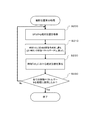
図5は、本実施形態に係る移動ベクトル算出処理の流れを示すフローチャートである。
先ず、処理部10は、ステップS100において移動ベクトルの算出タイミングであるか否かを判定する。移動ベクトルの算出タイミングは、手ぶれ判定時刻以降の任意のタイミングであり、有効センサーデータを使って移動ベクトルを算出するかどうかを判断する。また、センサー部14の検出時間間隔よりも長い時間間隔毎のタイミングである。移動ベクトルの算出周期は、例えば撮影者の移動速度により設定しても良い。
3. Process Flow FIG. 5 is a flowchart showing the flow of the movement vector calculation process according to the present embodiment.
First, in step S100, the
移動ベクトルの算出タイミングであると判定した場合(Yes)、処理部10は、ステップS110において所定時間分のセンサー部の検出結果に基づいて移動ベクトルを算出する。移動ベクトルの大きさは、加速度センサーの検出結果を積分することで算出される。また、移動ベクトルの向きは、ジャイロセンサーの検出結果の積分値と、方位センサーの検出結果とを用いて算出される。
If it is determined that it is the calculation timing of the movement vector (Yes), the
次いで、処理部10は、ステップS120において算出した移動ベクトルを算出に使用した有効センサーデータの時刻と対応付けて記憶部24の移動ベクトルデータ記憶部42に保存する。そして、処理部10は、先頭の処理に戻り、上記の処理を繰り返し実行する。
Next, the
図6は、本実施形態に係る撮影位置算出処理の一例である撮影位置算出処理の流れを示すフローチャートである。先ず、ステップS200においてGPSにより絶対位置を取得すると、ステップS210において絶対位置取得時刻に最も近い時刻の移動ベクトルデータを移動ベクトルデータ記憶部42から読み出す。図4(A)で説明すると、時刻「t6」対応する移動ベクトルデータ「g」を読み出す。ステップS220において絶対位置と移動ベクトルデータとを用いて時刻「t6」における絶対位置を算出する。この算出された時刻「t6」における絶対位置を起点に、時刻「t5」に対応する移動ベクトルデータを使って、時刻「t5」における絶対位置を算出する。
FIG. 6 is a flowchart showing the flow of the shooting position calculation process which is an example of the shooting position calculation process according to the present embodiment. First, when the absolute position is acquired by GPS in step S200, the movement vector data at the time closest to the absolute position acquisition time is read from the movement vector
移動ベクトルデータ記憶部42に保存されているデータは、絶対位置取得時刻に近い順に読み出され、上述のように順次計算に柿葉される。ステップS230において移動ベクトルデータ記憶部42に保存されたデータ全てを使用したら撮影位置算出処理は終了し、撮影時刻における撮影位置が決定される。
The data stored in the movement vector
移動ベクトルデータ記憶部42に保存されるデータは、移動ベクトルデータ記憶部42の内部で処理することで、一つのベクトルに合成し、絶対位置取得部からの絶対位置と組み合わせることで、撮影時刻における位置を算出しても良い。
The data stored in the movement vector
撮影位置算出処理を行った後、処理部10は、撮影場所添付処理を行う。具体的には、撮影位置算出処理で求めた撮影位置と記憶部24の地図データとを照査して、算出位置の位置座標が含まれる施設名を特定する。そして、特定した施設名を撮影画像と対応付けて、撮影画像DB26に記憶させる。
After performing the shooting position calculation process, the
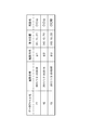
図7は、本実施形態に係る撮影画像DB26に格納されるデータの一例を示す図である。撮影画像DB26には、撮影画像のデータファイル名と、当該撮影画像の撮影日時と、当該撮影画像の撮影方向と、当該撮影画像の撮影時刻におけるデジタルカメラ2の位置として算出された算出位置と、当該算出位置が含まれる施設の名称である施設名とが対応付けて記憶される。なお、撮影のみが行われ、撮影場所の解析処理が行われていない場合には、当該撮影画像には、未だ算出位置と施設名とが対応付けられていない状態となる。
FIG. 7 is a diagram illustrating an example of data stored in the captured
2…デジタルカメラ 10…処理部 12…GPS受信部 14…センサー部 16…操作部 18…表示部 20…撮像部 22…計時部 24…記憶部 26…撮影画像DB 28…手ぶれ検出部 30…手ぶれ補正部 32…メインプログラム 34…移動ベクトル算出プログラム 36…位置算出プログラム 38…センサーデータ一時記憶部 40…有効センサーデータ記憶部 42…移動ベクトルデータ記憶部 44…絶対位置記憶部 46…地図データ部。
DESCRIPTION OF
Claims (4)
前記撮像装置の撮像部の手ぶれ振動を検出することと、
現在時刻を保持することと、
前記撮像装置の少なくとも加速度情報を含むセンサーデータを計測することと、
前記信号に基づいて前記撮像装置の絶対位置を算出することと、
前記検出された手ぶれ振動に基づく、単位時間あたりの手ぶれ補正信号検出回数が所定の回数を超えたか否かを判定することと、
前記手ぶれ補正信号検出回数が前記所定の回数を超えたと判定した場合に、前記所定の回数を超えたと判定した時刻以降の前記現在時刻と前記センサーデータとを対応付けて保存することと、
前記所定の回数を超えたと判定した時刻以降の撮影が実行された時刻以降に前記算出された絶対位置と、前記保存されたセンサーデータとを用いて、前記撮影が実行された時刻における前記撮像装置の位置を算出することと、
を含む、
位置算出方法。 A position calculation method for an image pickup apparatus having a positioning function for receiving a signal from a satellite and calculating a current position,
Detecting camera shake vibration of the imaging unit of the imaging device;
Keeping the current time,
Measuring sensor data including at least acceleration information of the imaging device;
Calculating an absolute position of the imaging device based on the signal;
Determining whether or not the number of camera shake correction signal detections per unit time exceeds a predetermined number based on the detected camera shake vibration;
When it is determined that the camera shake correction signal detection count exceeds the predetermined count, the current time after the time determined to exceed the predetermined count and the sensor data are stored in association with each other;
The imaging device at the time when the shooting is performed using the calculated absolute position and the stored sensor data after the time when the shooting is performed after the time when it is determined that the predetermined number of times has been exceeded. Calculating the position of
including,
Position calculation method.
前記保存されたセンサーデータを用いて移動方向及び移動距離を含む移動情報を算出することと、
前記撮影が実行された時刻以降に算出された絶対位置と前記移動情報とを用いて前記撮影が実行された時刻における前記撮像装置の位置を算出することと、
を含む、
請求項1に記載の位置算出方法。 Calculating the position of the imaging device
Calculating movement information including a moving direction and a moving distance using the stored sensor data;
Calculating the position of the imaging device at the time when the shooting was performed using the absolute position calculated after the time when the shooting was performed and the movement information;
including,
The position calculation method according to claim 1.
前記撮像部の電源供給量が所定値以下になった場合に開始される、
請求項1または2に記載の位置算出方法。 Calculating the absolute position is
Started when the power supply amount of the imaging unit is a predetermined value or less,
The position calculation method according to claim 1 or 2.
前記撮像装置の撮像部の手ぶれ振動を検出する手ぶれ検出部と、
前記撮像装置の少なくとも加速度情報を含むセンサーデータを計測するセンサー部と、
前記信号に基づいて前記撮像装置の絶対位置を算出する絶対位置取得部と、
処理部と、を含み、
前記処理部は、
単位時間あたりの手ぶれ補正信号検出回数が所定の回数を超えたと判定した場合に、前記所定の回数を超えたと判定した時刻以降の現在時刻と前記センサーデータとを対応付けて保存することと、
前記所定の回数を超えたと判定した時刻以降の撮影が実行された時刻以降に前記算出された絶対位置と、前記保存されたセンサーデータとを用いて、前記撮影が実行された時刻における前記撮像装置の位置を算出することと、
を行う、撮像装置。 An imaging apparatus having a positioning function for receiving a signal from a satellite and calculating a current position,
A camera shake detection unit that detects camera shake vibration of the imaging unit of the imaging device;
A sensor unit for measuring sensor data including at least acceleration information of the imaging device;
An absolute position acquisition unit that calculates an absolute position of the imaging device based on the signal;
A processing unit,
The processor is
When it is determined that the number of camera shake correction signal detections per unit time exceeds a predetermined number, the current time after the time determined to exceed the predetermined number and the sensor data are stored in association with each other;
The imaging device at the time when the shooting is performed using the calculated absolute position and the stored sensor data after the time when the shooting is performed after the time when it is determined that the predetermined number of times has been exceeded. Calculating the position of
An imaging device.
Priority Applications (1)
| Application Number | Priority Date | Filing Date | Title |
|---|---|---|---|
| JP2011168069A JP5857504B2 (en) | 2011-08-01 | 2011-08-01 | Position calculation method and imaging apparatus |
Applications Claiming Priority (1)
| Application Number | Priority Date | Filing Date | Title |
|---|---|---|---|
| JP2011168069A JP5857504B2 (en) | 2011-08-01 | 2011-08-01 | Position calculation method and imaging apparatus |
Publications (3)
| Publication Number | Publication Date |
|---|---|
| JP2013034049A JP2013034049A (en) | 2013-02-14 |
| JP2013034049A5 JP2013034049A5 (en) | 2014-09-11 |
| JP5857504B2 true JP5857504B2 (en) | 2016-02-10 |
Family
ID=47789565
Family Applications (1)
| Application Number | Title | Priority Date | Filing Date |
|---|---|---|---|
| JP2011168069A Expired - Fee Related JP5857504B2 (en) | 2011-08-01 | 2011-08-01 | Position calculation method and imaging apparatus |
Country Status (1)
| Country | Link |
|---|---|
| JP (1) | JP5857504B2 (en) |
Family Cites Families (4)
| Publication number | Priority date | Publication date | Assignee | Title |
|---|---|---|---|---|
| JP2000056386A (en) * | 1998-08-10 | 2000-02-25 | Olympus Optical Co Ltd | Camera |
| JP2007024832A (en) * | 2005-07-21 | 2007-02-01 | Seiko Epson Corp | TERMINAL DEVICE, TERMINAL DEVICE CONTROL METHOD, TERMINAL DEVICE CONTROL PROGRAM, COMPUTER-READABLE RECORDING MEDIUM CONTAINING TERMINAL DEVICE CONTROL PROGRAM |
| JP4670622B2 (en) * | 2005-12-12 | 2011-04-13 | ソニー株式会社 | Information processing apparatus, information processing method, and computer program |
| JP4968320B2 (en) * | 2009-12-25 | 2012-07-04 | カシオ計算機株式会社 | Information acquisition device, position information storage method and program |
-
2011
- 2011-08-01 JP JP2011168069A patent/JP5857504B2/en not_active Expired - Fee Related
Also Published As
| Publication number | Publication date |
|---|---|
| JP2013034049A (en) | 2013-02-14 |
Similar Documents
| Publication | Publication Date | Title |
|---|---|---|
| KR101256543B1 (en) | Image capturing apparatus, image capturing method, and storage medium | |
| US8552909B2 (en) | Location calculating method and location calculating device | |
| JP6665572B2 (en) | Control program, control method, and computer | |
| JP5750862B2 (en) | Positioning device, positioning method and program | |
| JP4858608B2 (en) | POSITIONING DEVICE, POSITIONING METHOD, PROGRAM, AND IMAGING DEVICE | |
| US11796685B2 (en) | Positioning control device | |
| US11340249B2 (en) | Electronic device, calibration control method, and storage medium storing program | |
| JP2012194149A (en) | Position registration device and position registration program | |
| KR101525224B1 (en) | A portable terminal of having the auto photographing mode | |
| JP5857504B2 (en) | Position calculation method and imaging apparatus | |
| US11805314B2 (en) | Control device, control method, and information processing system | |
| JP2016138864A (en) | Positioning device, positioning method, computer program and recording medium | |
| US9389318B2 (en) | Self-position measuring terminal | |
| JP2011247775A (en) | Positional information recorder, imaging apparatus provided with the same and recording method for positional information | |
| JP2012189467A (en) | Positioning device, pace per step data correction method and program | |
| JP2011082770A (en) | Data generation apparatus, method of controlling the same, and program | |
| KR101733792B1 (en) | Method and apparatus for correcting position | |
| JP2011199358A (en) | Imaging device with positioning function | |
| JP2015049446A (en) | Imaging device | |
| JP5773753B2 (en) | Imaging apparatus and control method | |
| JP2011133229A (en) | Device and method for positioning and program | |
| HK1166577B (en) | Image capturing apparatus and image capturing method | |
| JP2012058250A (en) | Positioning device, positioning method, program, and imaging apparatus |
Legal Events
| Date | Code | Title | Description |
|---|---|---|---|
| A521 | Request for written amendment filed |
Free format text: JAPANESE INTERMEDIATE CODE: A523 Effective date: 20140725 |
|
| A621 | Written request for application examination |
Free format text: JAPANESE INTERMEDIATE CODE: A621 Effective date: 20140725 |
|
| RD04 | Notification of resignation of power of attorney |
Free format text: JAPANESE INTERMEDIATE CODE: A7424 Effective date: 20150107 |
|
| A977 | Report on retrieval |
Free format text: JAPANESE INTERMEDIATE CODE: A971007 Effective date: 20150508 |
|
| A131 | Notification of reasons for refusal |
Free format text: JAPANESE INTERMEDIATE CODE: A131 Effective date: 20150602 |
|
| A521 | Request for written amendment filed |
Free format text: JAPANESE INTERMEDIATE CODE: A523 Effective date: 20150713 |
|
| A131 | Notification of reasons for refusal |
Free format text: JAPANESE INTERMEDIATE CODE: A131 Effective date: 20150811 |
|
| A521 | Request for written amendment filed |
Free format text: JAPANESE INTERMEDIATE CODE: A523 Effective date: 20151005 |
|
| TRDD | Decision of grant or rejection written | ||
| A01 | Written decision to grant a patent or to grant a registration (utility model) |
Free format text: JAPANESE INTERMEDIATE CODE: A01 Effective date: 20151117 |
|
| A61 | First payment of annual fees (during grant procedure) |
Free format text: JAPANESE INTERMEDIATE CODE: A61 Effective date: 20151130 |
|
| R150 | Certificate of patent or registration of utility model |
Ref document number: 5857504 Country of ref document: JP Free format text: JAPANESE INTERMEDIATE CODE: R150 |
|
| S531 | Written request for registration of change of domicile |
Free format text: JAPANESE INTERMEDIATE CODE: R313531 |
|
| R350 | Written notification of registration of transfer |
Free format text: JAPANESE INTERMEDIATE CODE: R350 |
|
| LAPS | Cancellation because of no payment of annual fees |