JP5857166B2 - Multi-function jug and beverage making machine using multi-function jug - Google Patents
Multi-function jug and beverage making machine using multi-function jug Download PDFInfo
- Publication number
- JP5857166B2 JP5857166B2 JP2015535138A JP2015535138A JP5857166B2 JP 5857166 B2 JP5857166 B2 JP 5857166B2 JP 2015535138 A JP2015535138 A JP 2015535138A JP 2015535138 A JP2015535138 A JP 2015535138A JP 5857166 B2 JP5857166 B2 JP 5857166B2
- Authority
- JP
- Japan
- Prior art keywords
- jug
- beverage
- container
- cover
- stirring device
- Prior art date
- Legal status (The legal status is an assumption and is not a legal conclusion. Google has not performed a legal analysis and makes no representation as to the accuracy of the status listed.)
- Expired - Fee Related
Links
Images


Classifications
-
- A—HUMAN NECESSITIES
- A47—FURNITURE; DOMESTIC ARTICLES OR APPLIANCES; COFFEE MILLS; SPICE MILLS; SUCTION CLEANERS IN GENERAL
- A47J—KITCHEN EQUIPMENT; COFFEE MILLS; SPICE MILLS; APPARATUS FOR MAKING BEVERAGES
- A47J31/00—Apparatus for making beverages
- A47J31/44—Parts or details or accessories of beverage-making apparatus
- A47J31/4403—Constructional details
-
- A—HUMAN NECESSITIES
- A47—FURNITURE; DOMESTIC ARTICLES OR APPLIANCES; COFFEE MILLS; SPICE MILLS; SUCTION CLEANERS IN GENERAL
- A47J—KITCHEN EQUIPMENT; COFFEE MILLS; SPICE MILLS; APPARATUS FOR MAKING BEVERAGES
- A47J31/00—Apparatus for making beverages
- A47J31/44—Parts or details or accessories of beverage-making apparatus
- A47J31/4489—Steam nozzles, e.g. for introducing into a milk container to heat and foam milk
-
- A—HUMAN NECESSITIES
- A47—FURNITURE; DOMESTIC ARTICLES OR APPLIANCES; COFFEE MILLS; SPICE MILLS; SUCTION CLEANERS IN GENERAL
- A47J—KITCHEN EQUIPMENT; COFFEE MILLS; SPICE MILLS; APPARATUS FOR MAKING BEVERAGES
- A47J43/00—Implements for preparing or holding food, not provided for in other groups of this subclass
- A47J43/04—Machines for domestic use not covered elsewhere, e.g. for grinding, mixing, stirring, kneading, emulsifying, whipping or beating foodstuffs, e.g. power-driven
- A47J43/044—Machines for domestic use not covered elsewhere, e.g. for grinding, mixing, stirring, kneading, emulsifying, whipping or beating foodstuffs, e.g. power-driven with tools driven from the top side
- A47J2043/04454—Apparatus of counter top type
- A47J2043/0449—Apparatus of counter top type with a mixing unit detachable from the support
Landscapes
- Engineering & Computer Science (AREA)
- Food Science & Technology (AREA)
- Mechanical Engineering (AREA)
- Apparatus For Making Beverages (AREA)
- Food-Manufacturing Devices (AREA)
- Devices For Dispensing Beverages (AREA)
Description
本発明は、飲料の調製のためのジャグ(jug)又は容器(container)、並びに飲料製造機械及びシステムに関する。 The present invention relates to a jug or container for the preparation of beverages, and beverage production machines and systems.
幾つかの飲料製造機械及びシステムが知られており、それらは、例えば、コーヒーをカップ内に直接的に計量分配(ディスペンス)するために、機械に設けられる計量分配注口又はノズルとの組み合わせにおいて、特殊な飲料の調製のためのジャグを使用する。例えば、泡立て牛乳(ミルク)、熱いインスタント飲料、冷たいコーヒー等を製造するために、製造されるべき飲料の種類に応じて、異なる形状及び構成を有するジャグが知られている。 Several beverage production machines and systems are known, for example in combination with a dispensing spout or nozzle provided in the machine, for example to dispense coffee directly into a cup. Use jugs for the preparation of special beverages. For example, to produce frothed milk (milk), hot instant beverages, cold coffee, etc., jugs having different shapes and configurations are known depending on the type of beverage to be produced.
WO2006/136268は、一組の異なるジャグを備えるコーヒーメーカー(コーヒー機械)を開示しており、各ジャグはある種類の飲料の調製に適し、各ジャグをコーヒーメーカーとの組み合わせにおいて用い得る。コーヒーメーカーは蒸気ノズルを備え、蒸気ノズルをジャグに接続して、様々な目的のために蒸気又は熱湯をジャグ内に計量分配し得る。コーヒーメーカーの柔軟性を増大させるために、幾つかの異なるジャグが必要とされ、ジャグは大量の空間を占め、特別なハウジングを必要とする。 WO 2006/136268 discloses a coffee maker (coffee machine) with a set of different jugs, each jug suitable for the preparation of certain types of beverages, and each jug can be used in combination with a coffee maker. The coffee maker is equipped with a steam nozzle, which can be connected to the jug to dispense steam or hot water into the jug for various purposes. In order to increase the flexibility of the coffee maker, several different jugs are required, which occupies a large amount of space and requires a special housing.
EP2186456は、シェークされた飲料、具体的には、冷たいシェークされたコーヒーを調製するための装置を開示している。そこに開示される実施態様の1つにおいて、この既知の装置はコーヒー調製ユニットを含み、コーヒー調製ユニットをコーヒー計量分配注口及びシェーカーに選択的に接続し得る。シェーカーを機械内に導入し、コーヒーメーカーの底に配置されるモータを用いて、機械内に回転式に配置されるブレードを回転させ得る。ブレードはシェーカー内に配置される角氷を粉砕するために用いられる。 EP 2186456 discloses an apparatus for preparing shaked beverages, in particular cold shaked coffee. In one of the embodiments disclosed therein, the known device includes a coffee brewing unit, which can be selectively connected to a coffee dispensing spout and a shaker. A shaker can be introduced into the machine, and a motor placed at the bottom of the coffee maker can be used to rotate a blade that is placed rotationally in the machine. The blade is used to crush ice cubes placed in a shaker.
この既知の機械は、2つの異なる飲料、即ち、熱いコーヒー又は冷たいシェークされたーヒーの調製のためだけに設計されている。 This known machine is designed only for the preparation of two different beverages: hot coffee or cold shaked coffee.
本発明によれば、飲料の調製のためのジャグであって、飲料の調製のために材料を受け入れるための少なくとも第1の容器と第2の容器とを備える本体と、第1の容器又は第2の容器内に配置されるように設計され且つ構成される少なくとも第1の攪拌装置と、本体を閉じるカバーと、飲料製造機械から材料を受け入れ且つ飲料を第1の容器内に収集するために配置される、飲料製造機械への第1の流体接続部と、第2の容器と流体連絡する、飲料製造機械への第2の流体接続部とを含む、ジャグが提供される。 According to the invention, a jug for the preparation of a beverage, comprising a body comprising at least a first container and a second container for receiving material for the preparation of the beverage, a first container or a second At least a first stirrer designed and configured to be disposed in the two containers, a cover for closing the body, and for receiving material from the beverage production machine and collecting the beverage in the first container A jug is provided that includes a first fluid connection to a beverage maker and a second fluid connection to a beverage maker in fluid communication with a second container.
2つの容器及びこれらの容器の一方に配置される少なくとも1つの攪拌装置は、ジャグの可撓性の改良をもたらす。例えば、熱い及び冷たいカプチーノ、熱い及び冷たいインスタント飲料、入れたての浸出コーヒー、インスタントコーヒー、ミルクコーヒー、アイスコーヒー、エスプレッソ、ホットチョコレート、並びに多くの他のもののような、広範な飲料を調製するために、2つの容器を選択的に或いは組合わせにおいて用い得る。 Two containers and at least one agitation device located in one of these containers provides an improvement in the flexibility of the jug. For example, to prepare a wide range of beverages such as hot and cold cappuccino, hot and cold instant beverages, freshly brewed coffee, instant coffee, milk coffee, iced coffee, espresso, hot chocolate, and many others In addition, two containers can be used selectively or in combination.
好適実施態様によれば、第2の攪拌装置が設けられる。第1の攪拌装置及び第2の攪拌装置をジャグに取り付け、第1の容器及び第2の容器内にそれぞれ位置付け得る。攪拌装置はジャグから取り外し可能であるのが好ましい。例えば、それらを選択的にジャグのカバーに接続し或いはジャグのカバーから分離させ得る。使用者の必要に応じて、攪拌装置の一方又は両方をジャグに接続し得る。従って、使用者は第1の攪拌装置、第2の攪拌装置、又はそれらの両方を使用するか否かを決定し得る。1つの攪拌装置だけが用いられるならば、他の攪拌装置がジャグに接続される必要はない。 According to a preferred embodiment, a second stirring device is provided. A first stirrer and a second stirrer may be attached to the jug and positioned in the first container and the second container, respectively. The agitator is preferably removable from the jug. For example, they can be selectively connected to or separated from the jug cover. Depending on the needs of the user, one or both of the agitators can be connected to a jug. Thus, the user can decide whether to use the first stirring device, the second stirring device, or both. If only one stirrer is used, no other stirrer need be connected to the jug.
一部の実施態様では、飲料製造機械から熱湯(高温水)又は蒸気を受け入れるために、飲料製造機械への第2の流体接続部を構成し且つ配置し得る。紅茶又は任意のインスタント飲料のような熱い飲料を調製するために、熱湯を用い得る。粒状又は固形の材料の希釈の改良のために、それぞれの攪拌装置を用い得る。水又は牛乳のような容器内に収容される冷たい液体を加熱するよう水を熱するために、蒸気を代替的に用い得る。例えば、熱い泡立て牛乳を製造するために、撹拌器の回転運動との組み合わせにおいて蒸気の供給を用い得る。容器内に牛乳を注ぎ入れ、その中に蒸気を送らずに攪拌装置を作動させることによって、同じジャグで冷たい泡立て牛乳も調製し得る。 In some embodiments, a second fluid connection to the beverage maker may be configured and arranged to receive hot water (hot water) or steam from the beverage maker. Hot water can be used to prepare a hot beverage such as black tea or any instant beverage. Each stirring device can be used to improve the dilution of granular or solid materials. Steam can alternatively be used to heat the water to heat a cold liquid contained in a container such as water or milk. For example, a steam supply can be used in combination with the rotational motion of a stirrer to produce hot frothed milk. Cold frothed milk can also be prepared in the same jug by pouring milk into the container and operating the stirrer without sending steam into it.
従って、例示的な実施態様において、第1の容器は第1の流体接続部と流体連絡するので、飲料製造機械によって生成される飲料は第1の容器内に計量分配(dispensed)される。飲料製造機械から蒸気又は熱湯を受け入れるために、第2の容器は第2の流体接続部と連絡する。 Thus, in an exemplary embodiment, the first container is in fluid communication with the first fluid connection so that the beverage produced by the beverage making machine is dispensed into the first container. The second container communicates with the second fluid connection to receive steam or hot water from the beverage maker.
好適な実施態様では、ジャグのカバーによって第1及び/又は第2の流体接続部を支持し得る。一部の実施態様では、第1の攪拌装置及び第2の攪拌装置もカバーによって支持される。これはジャグの使用をより簡単にし、ジャグの様々な部品の洗浄を容易化する。代替的な実施態様として第1及び/又は第2の攪拌装置をそれぞれの容器の底に配置することを排除しない。 In a preferred embodiment, the first and / or second fluid connection may be supported by a jug cover. In some embodiments, the first stirrer and the second stirrer are also supported by the cover. This makes the use of the jug easier and facilitates the cleaning of the various parts of the jug. As an alternative embodiment, it is not excluded to place the first and / or second stirring device at the bottom of each container.
第1の攪拌装置及び第2の攪拌装置は、適切な駆動装置を備え得る。一部の実施態様において、ジャグは、例えば、ジャグカバーによって支持されるか或いはジャグカバーに一体化される、ジャグに設けられる電気モータ構成を含み得る。これは攪拌装置がカバーによって支持されるときに特に適している。他の実施態様では、モータ構成を飲料製造機械内に配置し得る。モータ構成と飲料製造機械との間の機械的リンクをジャグに設け得る。しかしながら、モータ構成をジャグカバーに設けることは設計をより簡単にし、より頑強にし、且つより安価にする。攪拌装置がジャグ容器の底に配置されるならば、モータ構成をジャグの本体内に或いは飲料製造機械の底に設けられるハウジング内に配置し得る。モータ構成と攪拌装置との間に磁気伝動手段を設け得る。 The first stirrer and the second stirrer can be equipped with suitable drive devices. In some embodiments, the jug may include an electric motor configuration provided to the jug, for example, supported by or integrated with the jug cover. This is particularly suitable when the stirring device is supported by a cover. In other embodiments, the motor configuration may be located in the beverage production machine. A mechanical link between the motor configuration and the beverage production machine may be provided in the jug. However, providing the motor configuration on the jug cover makes the design simpler, more robust, and less expensive. If the agitator is located at the bottom of the jug container, the motor configuration can be located in the body of the jug or in a housing provided at the bottom of the beverage production machine. Magnetic transmission means may be provided between the motor configuration and the stirring device.
各攪拌装置はその独自のモータを備え得る。他の実施態様において、電気モータ構成は、第1の攪拌装置及び第2の攪拌装置の両方を駆動して回転させる単一の電気モータを含む。回転運動を両方の攪拌装置に伝達するために、機械的リンク、例えば、プーリ−ベルト構成を設け得る。単一の電気モータの使用はジャグをよりコンパクトにし、より安価にし、且つより確実にする。 Each stirrer can have its own motor. In other embodiments, the electric motor configuration includes a single electric motor that drives and rotates both the first stirrer and the second stirrer. A mechanical link, for example a pulley-belt arrangement, can be provided to transmit the rotational movement to both agitators. The use of a single electric motor makes the jug more compact, cheaper and more reliable.
ジャグの適切な位置に配置される電気接点を用いて、ジャグに、例えば、ジャグ本体に、好ましくは、ジャグカバーに設けられる電気モータ構成に電力供給し得る。ジャグが飲料製造機械に正しく接続されるときにだけモータの給電が可能であるよう、これらの電気接点は機械側に設けられる接点と共同作用するように構成され且つ配置されるのが好ましい。 The electrical contacts located at the appropriate location of the jug can be used to power the jug, for example, the jug body, preferably an electric motor arrangement provided on the jug cover. These electrical contacts are preferably constructed and arranged to cooperate with contacts provided on the machine side so that the motor can be powered only when the jug is properly connected to the beverage production machine.
一部の実施態様において、電気接点並びに第1及び/又は第2の流体接続部は、例えば、飲料製造機械に設けられる窪み(niche)又は凹部(recess)内に配置される電気接点及びノズルと共同作用するために、互いに隣接して配置される。有利な実施態様では、凹部又は窪みを機械の正面パネルに設け得る。例えば、ジャグカバーは、流体接続部及び電気接点をその上に配置するノーズ(nose)又は突起(projection)を備え得る。 In some embodiments, the electrical contacts and the first and / or second fluid connections are, for example, electrical contacts and nozzles disposed in a niche or recess provided in the beverage production machine. In order to work together, they are placed adjacent to each other. In an advantageous embodiment, recesses or depressions can be provided in the front panel of the machine. For example, the jug cover may include a nose or projection on which the fluid connection and electrical contacts are placed.
一部の実施態様において、第1の攪拌装置及び第2の攪拌装置は、洗浄目的のためにカバーから取り外し可能であるのが好ましい。カバーへの及びカバーからの、より具体的には、ジャグカバーによって支持される回転シャフトのような駆動手段への及び駆動手段からの、攪拌装置の容易な係合及び分離のために、迅速な機械的接続(fast mechanical connection)、例えば、スナップ接続(snap connection)を提供し得る。 In some embodiments, the first stirrer and the second stirrer are preferably removable from the cover for cleaning purposes. Because of the easy engagement and disengagement of the stirring device to and from the cover, more specifically to and from the drive means such as a rotating shaft supported by the jug cover A mechanical connection (fast mechanical connection), for example a snap connection (snap connection) may be provided.
ジャグの可撓性を更に改良して取扱いを容易にするために、一部の実施態様において、ジャグは、第1の容器及び第2の容器の一方に、例えば、第2の容器に液体を導入するための通路を含み、第2の流体接続部を通じて蒸気又は熱湯を計量分配し得る。よって、使用者が液体、例えば、牛乳を第2の容器内に注ぎ入れ、次に、飲料製造機械を作動させて、液体を加熱するために、例えば、熱い牛乳又は熱い泡立て牛乳を製造するために、熱湯又は蒸気を計量分配することが可能である。 In order to further improve the flexibility of the jug to facilitate handling, in some embodiments, the jug may contain liquid in one of the first container and the second container, eg, in the second container. A passage for introduction may be included and steam or hot water may be dispensed through the second fluid connection. Thus, the user pours a liquid, eg milk, into the second container and then operates the beverage production machine to heat the liquid, eg to produce hot milk or hot frothed milk. It is possible to dispense hot water or steam.
有利な実施態様において、通路はジャグカバーに形成される。特に有利な実施態様において、ジャグは通路の入口孔を閉じる取外し可能な上方部分を含み得る。使用者による容易なアクセスを向上させるために、一部の実施態様において、通路の入口孔はハンドルの上部に配置される。 In an advantageous embodiment, the passage is formed in the jug cover. In a particularly advantageous embodiment, the jug may include a removable upper portion that closes the inlet hole of the passage. To improve easy access by the user, in some embodiments, the passage inlet hole is located at the top of the handle.
第1及び第2の攪拌装置は互いに異なり得る。例えば、インスタント飲料又はコーヒー及び角氷を混ぜてアイスコーヒー又は同等物を製造するために、即ち、攪拌装置がその活性部分で容器の底付近に有利に配置される場合には、より長い攪拌装置を用い得る。攪拌装置の活性部分を容器内に収容される液体物質の自由表面又はその付近に配置することが必要とされる場合には、より短い攪拌装置を用い得る。例えば、熱い又は冷たい牛乳を泡立てるために、攪拌装置を牛乳の自由表面又はその付近に配置しなければならないので、空気及び牛乳が乳化させられて泡を形成するよう、攪拌装置の回転は気泡を牛乳中に捕捉させる。 The first and second stirring devices can be different from each other. For example, to mix instant beverages or coffee and ice cubes to produce iced coffee or the equivalent, i.e. where the stirrer is advantageously located near the bottom of the container in its active part, a longer stirrer Can be used. If it is necessary to place the active part of the stirrer on or near the free surface of the liquid substance contained in the container, a shorter stirrer can be used. For example, to stir hot or cold milk, the stirrer must be placed at or near the free surface of the milk, so rotation of the stirrer will cause bubbles to form so that air and milk are emulsified to form foam. Capture in milk.
一部の特に有利な実施態様では、2つの同一の攪拌装置が設けられる。これはジャグの使用をより容易にし且つ使い勝手をより良くする。それはジャグの製造も単純化する。何故ならば、より少数の構成部品、異なる構成部品が必要とされるからである。容器内の攪拌装置の異なる作用を得るために、第1の容器及び第2の容器は異なる深さを有し得る。即ち、第1の容器及び第2の容器の一方は、それらの他方よりも深くあり得る。その場合、2つの同一の攪拌装置は、それらが配置されるそれぞれの容器の底に対して異なる位置を取る。 In some particularly advantageous embodiments, two identical stirring devices are provided. This makes the use of the jugs easier and easier to use. It also simplifies the production of jugs. This is because fewer components and different components are required. In order to obtain different effects of the stirring device in the container, the first container and the second container may have different depths. That is, one of the first container and the second container can be deeper than the other of them. In that case, the two identical stirring devices take different positions with respect to the bottom of the respective container in which they are placed.
ジャグの本体は、第1の容器及び第2の容器の両方から飲料を注ぐために配置され且つ構成される注ぎ舌(pouring lip)を備え得る。一部の実施態様において、注ぎ舌は第1の容器及び第2の容器の両方と流体連絡し得るので、2つの容器内で同時に調製される飲料を同時に注ぎ得る。例えば、注ぎ舌は、注ぎ舌を第1の部分と第2の部分とに分割する中間隔壁を備え得る。第1の部分及び第2の部分は、第1の容器及び第2の容器からそれぞれ飲料を受け入れるために配置される。 The body of the jug may comprise a pouring lip arranged and configured for pouring beverage from both the first container and the second container. In some embodiments, the pour tongue can be in fluid communication with both the first container and the second container so that beverages prepared simultaneously in the two containers can be poured simultaneously. For example, the pouring tongue may comprise an intermediate septum that divides the pouring tongue into a first portion and a second portion. The first portion and the second portion are arranged to receive beverages from the first container and the second container, respectively.
特に有利な実施態様において、カバーは、ジャグの本体に係合可能な下方部分と、下方部分に係合可能であり且つ下方部分から分離可能である中間部分と、取外し可能な上方部分とを含み、中間部分は、第1の攪拌装置及び第2の攪拌装置を支持する。有利には、攪拌装置を駆動させるためのモータ(複数のモータ)をカバーの中間部分内に収容し得る。カバーの下方部分は、カバーの中間部分に収容されるモータ構成への接続のために攪拌装置を導入する通路又は孔を備え得る。容器の一方に液体を注ぎ入れるための通路が設けられるとき、有利には、通路をカバーの下方部分に形成し得る。カバーの下方部分及び中間部分は、第1の容器に向かう通路を共に形成し得る。 In a particularly advantageous embodiment, the cover comprises a lower part engageable with the body of the jug, an intermediate part engageable with the lower part and separable from the lower part, and a removable upper part. The intermediate portion supports the first stirring device and the second stirring device. Advantageously, the motor (s) for driving the stirring device can be accommodated in the middle part of the cover. The lower part of the cover may be provided with a passage or hole for introducing a stirring device for connection to a motor arrangement housed in the middle part of the cover. When a passage for pouring liquid into one of the containers is provided, the passage can advantageously be formed in the lower part of the cover. The lower part and the middle part of the cover may together form a passage towards the first container.
一部の実施態様において、ジャグのカバーは、カバーに対して傾斜可能であり且つ休止位置において弾性的に付勢される孔付き壁を備え得る。休止位置において、孔付き壁はカバーに形成される通路を横断して延びる。通路はジャグ内に材料を導入するために配置される。孔付き壁は、休止位置において孔付き壁を付勢する弾性部材に対してジャグ本体の内部に向かって内向きに傾斜するために構成され且つ配置される。孔付き壁を傾斜させることによって、固形材料、例えば、角氷を容器内に導入し得る。孔付き壁は存在し得る固体残留物を保持し、それらがジャグから注がれるのを防止する。 In some embodiments, the jug cover may comprise a perforated wall that is tiltable relative to the cover and is resiliently biased in the rest position. In the rest position, the perforated wall extends across a passage formed in the cover. The passage is arranged for introducing material into the jug. The perforated wall is configured and arranged to tilt inward toward the interior of the jug body relative to an elastic member that biases the perforated wall in the rest position. By tilting the perforated wall, solid material, such as ice cubes, can be introduced into the container. The perforated walls retain solid residues that may be present and prevent them from being poured from the jugs.
更なる特徴によれば、飲料製造機械を含むシステムであって、飲料製造機械は、飲料製造ユニットと、飲料ディスペンサと、飲料出口ノズルと、切換え部材と、上述のようなジャグとを含み、飲料ディスペンサは、飲料ディスペンサの下に配置されるカップ内に飲料を計量分配するために配置され、飲料出口ノズルは、飲料出口ノズルに接続されるジャグに飲料を計量分配するために配置され、切換え部材は、飲料製造ユニットを、選択的に、飲料ディスペンサ又は飲料出口ノズルに流体的に接続する、システムが提供される。 According to a further feature, a system comprising a beverage production machine comprising a beverage production unit, a beverage dispenser, a beverage outlet nozzle, a switching member and a jug as described above, The dispenser is arranged for dispensing the beverage in a cup arranged under the beverage dispenser, the beverage outlet nozzle is arranged for dispensing the beverage in a jug connected to the beverage outlet nozzle, and the switching member A system is provided that selectively fluidly connects a beverage production unit to a beverage dispenser or beverage outlet nozzle.
本発明の更なる機能及び利点を、その例示的な実施態様の以下の記載中に並びに本記載の一体的な部分を形成する付属の請求項中に示す。 Further features and advantages of the invention are set forth in the following description of exemplary embodiments thereof and in the appended claims forming an integral part of the description.
本発明の1つの例示的な非限定的な実施態様を示す添付の図面と共に考察するとき、本発明の及びその利点の多くのより完全な理解は、それらが以下の詳細な記載を参照することによってより十分に理解されるようになるときに、直ちに得られるであろう。 For a more complete understanding of the present invention and its advantages, when viewed in conjunction with the accompanying drawings illustrating one exemplary non-limiting embodiment of the present invention, reference is made to the following detailed description. Will be obtained immediately when it becomes more fully understood.
例示的な実施態様の以下の詳細な記載は、添付の図面を参照する。異なる図面中の同じ参照番号は、同じ又は類似の要素を特定する。加えて、図面は必ずしも原寸通りに描かれていない。また、以下の詳細な記載は本発明を限定しない。むしろ、本発明の範囲は付属の請求項によって定められる。 The following detailed description of exemplary embodiments refers to the accompanying drawings. The same reference numbers in different drawings identify the same or similar elements. In addition, the drawings are not necessarily drawn to scale. Also, the following detailed description does not limit the invention. Rather, the scope of the present invention is defined by the appended claims.
本明細書を通じた「1つの実施態様」又は「(ある)実施態様」又は「一部の実施態様」への言及は、(ある)実施態様に関連して記載される機能、構成又は特徴が、開示される主題の少なくとも1つの実施態様に含まれることを意味する。よって、本明細書を通じた様々な場所における「1つの実施態様において」又は「(ある)実施態様において」又は「一部の実施態様において」という成句の出現は、必ずしも同じ実施態様を指さない。更に、特定の機能、構成又は特徴を、」1つ又はそれよりも多くの実施態様において任意の適切な方法において組み合わせ得る。 References to “one embodiment” or “(an) embodiment” or “some embodiments” throughout this specification refer to functions, configurations or features described in connection with the (an) embodiment. , Is meant to be included in at least one embodiment of the disclosed subject matter. Thus, the appearance of the phrase “in one embodiment” or “in (an) embodiment” or “in some embodiments” in various places throughout this specification is not necessarily referring to the same embodiment. . Furthermore, the particular functions, configurations or features may be combined in any suitable manner in one or more embodiments.
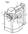
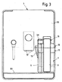
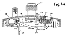
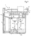
添付の図面において、ジャグは全体的に符号1で印され、飲料製造機械、例えば、コーヒーメーカー(コーヒー製造機械)、カプチーノメーカー又は同等物への接続のために設計される。図3は、飲料製造機械3を含むシステムを例示している。飲料製造機械3にはジャグ1が接続されており、飲料製造機械3の正面パネルが図4に示されている。
In the accompanying drawings, the jug is generally designated 1 and is designed for connection to a beverage maker, for example a coffee maker (coffee maker), a cappuccino maker or the like. FIG. 3 illustrates a system including a
ジャグ1は、ジャグ本体5と、ジャグカバー7とを含み、ジャグカバー7は、後により詳細に記載する幾つかの構成部品から成る。ジャグ1は、ジャグハンドル9を更に含む。
The
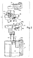
図2に最良に示すように、ジャグ1のカバー7は、下方部分11と、中間部分13と、頂部分15とを含む。ここで以下により詳細に説明するように、下方部分11をジャグ1の本体5にスナップ嵌めし得る。下方部分11は一対の攪拌装置17及び19のための通路を含み、攪拌装置17及び19は中間カバー部分13上での回転のために支持される。カバー部分13に容易に接続され且つカバー部分13から容易に切り離されるように攪拌装置を設計し且つ構成し得る。例えば、差込み式の接続を設け得る。使用者は、使用者が製造することを欲する飲料の種類に応じて、選択的に、1つの攪拌装置のみをジャグに接続し、両方の攪拌装置をジャグに接続し、或いは第1及び第2の攪拌装置のいずれをもジャグに接続しない。
As best shown in FIG. 2, the
他の実施態様では、2つの攪拌装置を異なる方法においてジャグに接続し得る。例えば、それらを容器(receptacle)の底に配置し得る。例えば、この場合には、磁性駆動部材を通じて、飲料製造機械内に配置されるモータ手段によって、攪拌装置を回転させ得る。 In other embodiments, the two agitators can be connected to the jug in different ways. For example, they can be placed at the bottom of the receptacle. For example, in this case, the stirrer can be rotated by motor means arranged in the beverage production machine through the magnetic drive member.
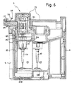
一部の実施態様では、攪拌装置がジャグのカバーによって支持されるとき、カバー部分13は2つの攪拌装置17及び19の回転のためのモータ21(例えば図6を参照)も収容する。図示しない他の実施態様では、2つの攪拌装置を駆動させるために、2つの異なるモータを設け得る。他の実施態様では、攪拌装置を回転させるために、異なる発動機又は異なる複数の発動機、例えば、飲料製造機械内に収容されるモータと機械的に接続可能なシャフトを用い得る。
In some embodiments, when the stirrer is supported by a jug cover, the
ジャグ1の本体5は、内部的には、2つの容器、即ち、第1の容器23及び第2の容器25を備え得る。2つの容器23及び25の形状及び配置は、カバー7がその上に取り付けられた状態のジャグ1が組立状態(図1、5−10)にあるときに、第1の攪拌装置17が第1の容器23内に導入され且つ第2の攪拌装置19が第2の容器25内に導入されるような形状及び配置である。
The
隔壁24によって2つの容器23及び25を分離し得る。図面に例示する例示的な実施態様に示すように、2つの容器23及び25は異なる深さを有し得る。例えば、第2の容器25は第1の容器23よりも深くあり得る。即ち、ジャグ1が使用の準備が整った垂直位置に配置されるとき、第2の容器25の底25Bは第1の容器23の底23Bよりも低い位置に配置される。
The two
実施態様において示すように、2つの攪拌装置17及び19は互いに同一であり得る。他の実施態様では、2つの攪拌装置は互いに異なり得る。更なる実施態様(図示せず)では、形状及び機能において異なる2つよりも多くの攪拌装置の組を設け得るので、1つの攪拌装置又は撹拌装置対或いは他の攪拌装置又は攪拌装置対17,19を選択することによって、同じジャグを用いて異なる材料を混ぜ得るし且つ/或いは異なる飲料を製造し得る。
As shown in the embodiment, the two
使用者は特別な容器23及び25のために及び/又は特別な飲料のために特別な攪拌装置を選択する必要がないので、2つの攪拌装置17,19を有することは使い勝手がより良い(よりユーザフレンドリーである)。
Having two
図面に示すような一部の実施態様では、単一の電気モータ21がカバー7内に、好ましくは、その中間部分13内に収容される。攪拌装置19は、例えば、電気モータ21のモータシャフト21Aに直接的に接続される。モータシャフト21Aから他の攪拌装置17に回転運動を伝達するために、カバー7内に機械的な伝動装置を設け得る。一部の実施態様(特に図8を参照)において、機械的な伝動装置は、歯付きホイール27を含み得る。歯付きホイール27はモータシャフト21Aに取り付けられて、モータシャフト21Aと共に回転する。第1の歯付きホイール27から第2の歯付きホイール29に回転運動を伝達するために、第2の歯付きホイール29及び歯付きベルト31を設け得る。第2の歯付きホイール29はシャフト33に取り付けられ、シャフト33と共に回転して、第1の攪拌装置17を回転させる。
In some embodiments as shown in the drawings, a single
プーリ−ベルト伝動装置の代わりに他の機械的リンクを用い得る。例えば、一部の場合には、歯車伝動装置が適し得る。 Other mechanical links may be used in place of the pulley-belt transmission. For example, in some cases, a gear transmission may be suitable.
カバー7の中間部分13は複数の電気接点35を支持し、それらの少なくとも一部はモータ21に電力供給するために配置され且つ構成される。例示的な実施態様では、カバー7から剛的に突出するプレート37の上に電気接点35を配置し得る。後により詳細に記載するように、飲料製造機械3内に設けられる対応する電気接点と相互作用するために、プレート37は垂直平面に従って進展し、カバー7から突出する。
The
図8から最良に分かるように、攪拌装置17及び19は、ジャグカバー7の底部分11に設けられる通路41及び43を通じて延びる。このようにして、底部分11をジャグ本体5の頂部に係合させ得るし、ジャグカバー7の中間部分13をジャグ本体5から取り外し得る。
As best seen in FIG. 8, the stirring
ジャグカバー7の中間部分13は、中間部分13から突出し且つカバー7がジャグ本体5の上に配置されるときにハンドル9と反対のジャグの側に配置される前方突起又はノーズ45(nose)を有する。ノーズ45は飲料製造機械3への接続のために構成され且つ配置される。
The
ノーズ45は、飲料製造機械3の正面パネル3Bの凹部3A(図4)に設けられる対応するスロット又は案内通路49内に係入する、側方ピン47を備え得る。
The
コネクタ、例えば、雄コネクタ51が、ノーズ45から前方に延び、飲料製造機械3の正面パネル3Bに設けられる前述の凹部3A内に収容されるコネクタ53、例えば、雌コネクタとの共作用のために設計される(図4)。他の実施態様において、コネクタ51は雌コネクタであってもよく、雄コネクタと共同作用(co-act)する。
A connector, for example, a
後により詳細に説明するように、コネクタ51は、飲料製造機械3内に配置される番号55で概略的に示される飲料製造ユニットによって製造される飲料を受け入れることを目的とする第1の接続部を形成する。飲料製造ユニット55は液圧回路に接続され、液圧回路は雄コネクタ51内の雌コネクタ53を通じて或いは飲料製造機械3の正面パネル3Bによって支持され且つドリップトレイ59より上に配置される飲料注口57を通じて飲料を選択的に計量分配(dispense)し得るように設計され、ドリップトレイ59の上には計量分配注口57から直接的に飲料を収集するためのカップCを配置し得る。飲料製造ユニット55は、例えば、エスプレッソコーヒーを製造するためのコーヒー浸出ユニット(coffee brewing unit)であり得るし、或いは他の飲料を製造するためであり得る。
As will be explained in more detail later, the
ノーズ45の正面に支持される雄コネクタ51は、特に図9に示すように、ジャグカバー7内に配置されるパイプ61と流体連絡する。一部の実施態様では、パイプ61をカバー7の中間部分13内に収容させ得る。パイプ61はコネクタ51からカバー7の中間部分13によって形成される第2のコネクタ63(特に図8を参照)に向かって延び得る。飲料製造機械3によって製造される飲料、例えば、コーヒーを、雌コネクタ53、雄コネクタ51、パイプ61、及び第2のコネクタ63を通じて第1の容器23内に直接的に計量分配し得るよう、コネクタ63は第1の容器23内に開口する。
The
飲料の調製のための1つ又はそれよりも多くの追加的な又は代替的な材料を、ジャグカバー7に設けられる孔を通じて第1の容器23内に導入させ得る。一部の実施態様では、図2から最良に分かるように、カバー7の中間部分13は貫通路65を形成し得る。カバー7が本体5の上に配置されるとき、貫通路65は第1の容器23より上に配置される。カバー7の中間部分13によって形成される貫通路65は、カバー7の下方部分11によって形成される第2の貫通路67に整列させられる。カバー7全体が組み立てられて、ジャグ1の本体5の上に配置されるとき、貫通路65,67はカバー7の上方部分15によって閉じられる。頂部分15が取り外すことによって、通路65,67を通じて第1の容器23へのアクセスを得ることができる。
One or more additional or alternative materials for beverage preparation may be introduced into the
例えば、角氷又は同等物を容器23内に導入するために、通路65,67によって形成される大きな孔を用い得る。
For example, large holes formed by the
好適な実施態様では、取り外し可能な孔付き壁69がカバー7の下方部分11によって旋回的に支持される。孔付き壁69を二重矢印に従って傾斜させ得る。孔付き壁69は、弾性部材、例えば、付勢バネによって、図2に示される休止位置、即ち、孔付き壁69が貫通路65,67を部分的に閉じる位置に向かって、弾性的に付勢される。孔付き壁69を頂部から内向きに押すことによって、孔付き壁は矢印f69に従って旋回して、容器23内への角氷又は同等物の導入を可能にする。休止位置に配置されるとき、孔付き壁69は大きな氷片が容器23から注ぎ出されるのを防止し、よって、アイス飲料、例えば、アイスコーヒーの調製を容易化する。
In a preferred embodiment, a removable
攪拌装置17を回転させることにより角氷を粉砕し或いは角氷を溶解させ且つ飲料製造機械3によって計量分配される熱い(高温の)コーヒーを冷やすことによってアイスコーヒーを製造するために、パイプ61を通じて飲料製造機械3によって計量分配される熱いコーヒーと共に容器23内に導入される角氷を用い得る。一部の実施態様では、使用者が冷たい(低温の)コーヒー又はアイスコーヒーを調製することを欲するときに、より低温のコーヒーを計量分配し得るように飲料製造装置3を構成し得るので、角氷を粉砕し或いは溶解させることによってコーヒーを冷却することがより効果的になる。
Through the
一部の実施態様では、角氷を粉砕するのに適した形状を有する攪拌装置17を用い得る。例えば、攪拌装置17はブレードを備え得る。しかしながら、これは必須でない。コーヒーのような熱い飲料と角氷との間の熱交換を改良することによって氷の溶解を促進し或いは加速させるために、その構造が液体飲料及び角氷をその中で混ぜるように設計され且つ構成される、異なる形状の攪拌装置を想起し得る。攪拌装置17を回転させるために、より少ない電力が必要とされる。その上、この場合には、他の操作にも適した、例えば、牛乳泡立てにも適した、攪拌装置を用い得る。よって、2つの同一の攪拌装置17,19を2つの容器内に設けて、上記のように、装置の使用をより容易にする。
In some embodiments, an
一部の実施態様において、ジャグ本体5は二重注ぎ舌73(double pouring lip)を備えるのが有利である。カバー7全体が組み立てられて、ジャグ本体5の上に配置されるとき、二重注ぎ舌73はカバー7の上方部分15によって閉じられる。この目的のために、カバー7の上方部分15は側方拡張部15A(図1及び2を参照)を備える。カバー7の上方部分15を取り外すことによって、第1の容器23にアクセス可能であり、飲料をジャグ1から、例えば、カップ、グラス、又は同等物内に注ぎ得る。
In some embodiments, the
図2から最良に分かるように、一部の実施態様において、注ぎ舌73は中間隔壁75を備え、中間隔壁75は注ぎ舌73を2つの部分73A及び73Bに分割する。容器23内に収容される飲料は注ぎ舌73の部分73Aを通じて注がれるのに対し、ジャグ1の第2の容器25内に収容される飲料は注ぎ舌73の部分73Bを通じて注がれる。よって、ジャグ1の2つの容器23及び25内で同時に調製される2つの異なる飲料を注ぎ入れることが可能であり、2つの飲料がジャグから注がれるまで、それらを別個に維持する。これは例えば冷たいカプチーノを調製するために特に有利である。熱いコーヒー及び氷を他の容器内に維持して、別個の容器内で冷たい牛乳を攪拌装置19で泡立てることは、より効率的な泡立て及びより良好な品質の最終製品をもたらす。
As best seen in FIG. 2, in some embodiments, the pouring
二重注ぎ舌73を提供することは、例えば、カップ内の2つの部分(泡立て牛乳及び冷たいコーヒー)の計量分配をより容易にし、且つ使い勝手をより良くする。
Providing a double pouring
他の実施態様では、2つの別個の注ぎ舌、ジャグの2つの容器の各々のために1つ注ぎ舌を設け得る。しかしながら、そのような構成は二重注ぎ操作を必要にする。 In other embodiments, two separate pour tongues may be provided, one pour tongue for each of the two jug containers. However, such a configuration requires a double pouring operation.
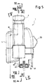
一部の実施態様において、飲料製造機械3は、凹部3A内に配置される1つ又はそれよりも多くの蒸気及び/又は水計量分配ノズルを備え得る(図4)。ノーズ45に設けられる対応する孔を通じて蒸気及び/又は水計量分配ノズルをジャグ1に接続し得る。図面に例示される実施態様において、ジャグ1は、1つだけのそのような蒸気/水ノズルへの接続のために設計される。この目的のために、ノーズ45は第2の容器25に向かう接続の一部を形成する頂部孔77(図5を参照)を備える。垂直方向又は近垂直方向に従って蒸気及び/又は熱湯計量分配ノズルを孔77内に導入して、ジャグ1を飲料製造機械3の蒸気/熱湯回路と流体連絡させ得る。他の実施態様において、計量分配ノズルの挿入は水平方向又は傾斜方向にあり得る。
In some embodiments, the
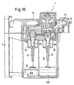
図6に最良に示されるように、一部の実施態様において、ノーズ45の内側には部材79が収容され、部材79はその中に形成される蒸気及び/又は熱湯経路81を有する。蒸気及び/又は熱湯経路81はノーズ45の頂部に設けられる孔77と流体連絡する。次いで、蒸気及び/又は熱湯経路81は中間カバー部分13に配置されるチューブ83(管)と流体連絡する。チューブ83は中間カバー部分13の底壁13Aを通じて延びるコネクタ85に更に接続され得るし、チューブ83から更なるチューブ又はパイプ87への流路をもたらす。チューブ又はパイプ87は、カバー7の下方部分11に形成される通路を通じて、第2の容器25の底25Bに向かって下向きに延びる。図6に示されるように、パイプ87は容器25の殆ど底25Bまで下向きに延び得る。
As best shown in FIG. 6, in some embodiments, a
中間カバー部分13が下方カバー部分11から取り外されるときに、パイプ87をコネクタ85に拘束させ且つコネクタ85と共に取り外し得る。代替的に、コネクタ85が中間カバー部分13と共に取り外されるときに、パイプ87を下方カバー部分11に拘束させ下方カバー部分11に取り付けられたままとし得る。
When the
この構成を用いて熱湯又は蒸気を第2の容器25内に計量分配し得る。カバー7内に形成されるある種のレース又は通路を通じて、追加的な材料を第2の容器25内に装填し得、図7及び8で見るときに最良に示される。通路は番号89で印され、下方カバー部分11に形成される。通路89は通路入口孔89Aを有する。この孔89Aをハンドル9の上に配置し得る。この孔89Aは水平に亘って僅かな傾斜を伴って延び、第2の容器25の上に配置される下方出力端孔89Bに達する。上方カバー部分15によって通路89を閉じ得る。上方カバー部分15が残余の中間カバー部分13及び下方カバー部分11から取り外されるときには、入口孔89Aを通じた通路89へのアクセスが得られる。材料、例えば、好ましくは、牛乳のような液体材料を、孔89A及び通路89を通じて、第2の容器25内に注ぎ込み得る。
This configuration can be used to dispense hot water or steam into the
例えば、熱い牛乳又は泡立て牛乳を調製するために、第2の容器25を用い得る。この目的のために、通路89を通じて冷たい牛乳を第2の容器25内に注ぎ得る。牛乳が容器25内に導入されるや否や、頂部カバー部分15をその閉塞位置(図7)において交換し、ジャグ1をノーズ45に設けられる孔77及び蒸気及び/又は熱湯経路81を通じて飲料製造機械3内に配置される蒸気生成器(図示せず)と流体連絡させ得る。蒸気が通路81を通じて計量分配されるならば、第2の容器25内に収容される牛乳を加熱し得る。攪拌装置19が駆動させられて回転するならば、牛乳を泡立て得る。よって、熱い泡立て牛乳を得ることができる。蒸気が計量分配されず、攪拌装置19が回転させられるならば、冷たい泡立て牛乳が生成される。
For example, the
好適実施態様において、第2の容器25は第1の容器23よりも深いので、攪拌装置19の下方部分は容器25の底からある距離に配置される。泡立て牛乳が望ましいとき、第2の容器25内に導入される牛乳の量は、攪拌装置19の下方部分に達するような量である。よって、攪拌装置の回転は空気を牛乳中に押し込み、牛乳泡を生む。異なる深さを有する容器23,25を設けることによって、液体レベルに対する及びそれぞれの容器23,25の底に対する攪拌装置の位置に応じて、2つの異なる機能を果たすために、2つの同一の攪拌装置17,19を設け得る。
In a preferred embodiment, the
熱湯を経路81を通じて第2の容器25内に計量分配することによって、熱い飲料、例えば、紅茶又はインスタントコーヒーを同じジャグで製造し得る。
By dispensing hot water through the
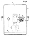
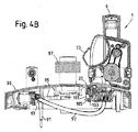
図4、4A及び4Bは、ジャグ1と飲料製造機械3との間の結合を設計する可能な方法を例示している。図4A及び4Bは、ジャグ1が取り外された状態(図4A)及びジャグが機械に取り付けられた状態(図4B)の、飲料製造機械3の正面パネル3Bの図4の線AB−ABに沿う断面を例示している。
4, 4A and 4B illustrate possible ways of designing the coupling between the
図4A及び4Bにおいて、参照番号91は、飲料製造ユニット55、例えば、コーヒー浸出ユニットへの接続のために設けられるチューブを指している。チューブ91は、代替的に及び選択的に、計量分配注口57又は雌コネクタ53と流体連絡する。この目的を達成するために、チューブ91を三方向電子弁93に接続し得る。三方向電子弁93は、チューブ91を、選択的に、第1のホース95又は第2のホース97と流体連絡させ得る。
4A and 4B,
チューブ91が弁93を介して第1のホース95と連絡するとき、飲料製造ユニット55によって製造される飲料は、注口57を通じて、例えば、ドリップトレイ59上に配置されるカップC内に直接的に計量分配される(図3及び4)。
When the
チューブ91が弁93を介して第2のホース97と流体連絡させられるとき、飲料製造ユニット55によって製造される飲料は、雌コネクタ53を通じてジャグ1に計量分配される。この目的を達成するために、ジャグは図3及び4Bに示されるように機械に正しく接続されなければならない。飲料製造機械3へのジャグ1の正しい接続を検出し、それにより、チューブ91がホース97と流体連絡させられる位置における電子弁93の切換えを可能にするために、マイクロスイッチ又は任意の他の種類のセンサを設け得る。ジャグ1が機械3に正しく接続されていないならば、センサはこの状態における電子弁93の切換えを禁じ、飲料の計量分配は第1のホース95又は注口57を通じてのみ可能である。
When the
図4A及び4Bは、ジャグ1と飲料製造機械3のハウジング内に配置される電気回路との間で電気接続がどのように達成されるかも示している。この実施態様では、内側電気接点99が旋回アーム101上で支持され、旋回アーム101は符号103で飲料製造機械3の正面パネル3Bに蝶番付けされる。旋回アーム101を図4Aに示される休止位置に向かって付勢するために、弾性部材、例えば、バネ105を設け得る。旋回アーム101は付加物107を備え得る。旋回アーム101が休止位置にあるとき、付加物107は機械ハウジングの外側からアクセス可能なシート109の内側に突出する。図4Aに示されるように、ジャグ1が飲料製造機械3に取り付けられないとき、付加物107はシート109内に突出する。
4A and 4B also show how an electrical connection is achieved between the
ジャグ1が飲料製造機械3に接続されるときには、プレート37がシート109に入り、付加物107をシートから外に押し出し、内側電気接点99が適切なスロットを通じてシート109内に突出するまで、旋回アーム101を軸103の周りで旋回させる。よって、プレート37上に設けられる接点35が内側電気接点99に対して押し付けられ、ジャグ1に搭載される電気及び/又は電子構成部品、例えば、電気モータ21を励磁し且つ作動させ得る。
When the
ここに記載する主題の開示の実施態様を図面に示し且つ幾つかの例示的な実施態様において具体的に且つ詳細に十分に記載したが、付属の請求項において引用される主題の利点、ここに示される原理及び着想、及び新規な教示から実質的に逸脱することなく、多くの変形、変更、及び省略が可能であることが、当業者に明らかである。故に、開示の革新の適切な範囲は、全てのそのような変形、変更、及び省略を包含するよう、付属の請求項の最広義の解釈によってのみ決定されるべきである。「含む」という用語は、請求項中に列挙される要素又はステップ以外の要素又はステップの存在を排除しない。ある要素に先行する不定冠詞の存在は、複数のそのような要素の存在を排除しない。幾つかの手段を列挙する装置の請求項では、1つ且つ同一のハードウェアの品目によって、これらの手段の幾つかを具現し得る。特定の手段が相互に異なる従属項において引用されているという単なる事実は、これらの手段の組合わせを有利に用い得ないことを示さない。 The disclosed embodiments of the subject matter described herein are shown in the drawings and have been described with particularity and detail in some illustrative embodiments, but the advantages of the subject matter recited in the appended claims, here It will be apparent to those skilled in the art that many variations, modifications, and omissions can be made without departing substantially from the principles and concepts shown and the novel teachings. Accordingly, the proper scope of the disclosed innovations should only be determined by the broadest interpretation of the appended claims to encompass all such variations, modifications, and omissions. The word “comprising” does not exclude the presence of elements or steps other than those listed in a claim. The presence of an indefinite article preceding an element does not exclude the presence of a plurality of such elements. In the device claim enumerating several means, several of these means can be embodied by one and the same item of hardware. The mere fact that certain measures are recited in mutually different dependent claims does not indicate that a combination of these measured cannot be used to advantage.
Claims (17)
飲料の調製のために材料を受け入れるための少なくとも第1の容器と第2の容器とを備える本体と、
前記第1の容器及び前記第2の容器の一方への配置のために設けられる少なくとも第1の攪拌装置と、
前記本体を閉じるカバーと、
飲料製造機械から材料を受け入れ且つ前記飲料を前記第1の容器内に収集するために配置される、第1の流体接続部と、
前記第2の容器と流体連絡する、飲料製造機械への第2の流体接続部とを含む、
ジャグ。 A jug for the preparation of a beverage,
A body comprising at least a first container and a second container for receiving ingredients for the preparation of a beverage;
At least a first stirring device provided for placement in one of the first container and the second container;
A cover for closing the body;
A first fluid connection arranged to receive material from a beverage production machine and to collect the beverage in the first container;
A second fluid connection to a beverage production machine in fluid communication with the second container.
Jug.
前記飲料製造機械は、
飲料製造ユニットと、
飲料ディスペンサと、
飲料出口ノズルと、
切換え部材と、
請求項1乃至14のうちのいずれか1項に記載のジャグとを含み、
前記飲料ディスペンサは、前記飲料ディスペンサの下に配置されるカップ内に前記飲料を計量分配するために配置され、
前記飲料出口ノズルは、前記飲料出口ノズルに接続されるジャグに前記飲料を計量分配するために配置され、
前記切換え部材は、前記飲料製造ユニットを、選択的に、前記飲料ディスペンサ又は前記飲料出口ノズルに流体的に接続する、
システム。 A system comprising a beverage production machine,
The beverage production machine is:
A beverage production unit;
A beverage dispenser;
A beverage outlet nozzle;
A switching member;
A jug according to any one of claims 1 to 14,
The beverage dispenser is disposed for dispensing the beverage in a cup disposed under the beverage dispenser;
The beverage outlet nozzle is arranged for dispensing the beverage into a jug connected to the beverage outlet nozzle;
The switching member selectively fluidly connects the beverage production unit to the beverage dispenser or the beverage outlet nozzle;
system.
Applications Claiming Priority (3)
| Application Number | Priority Date | Filing Date | Title |
|---|---|---|---|
| US201261710066P | 2012-10-05 | 2012-10-05 | |
| US61/710,066 | 2012-10-05 | ||
| PCT/IB2013/058883 WO2014053963A1 (en) | 2012-10-05 | 2013-09-26 | Multi-functional jug and beverage producing machine using same |
Publications (2)
| Publication Number | Publication Date |
|---|---|
| JP2015535721A JP2015535721A (en) | 2015-12-17 |
| JP5857166B2 true JP5857166B2 (en) | 2016-02-10 |
Family
ID=49765583
Family Applications (1)
| Application Number | Title | Priority Date | Filing Date |
|---|---|---|---|
| JP2015535138A Expired - Fee Related JP5857166B2 (en) | 2012-10-05 | 2013-09-26 | Multi-function jug and beverage making machine using multi-function jug |
Country Status (7)
| Country | Link |
|---|---|
| US (1) | US10517423B2 (en) |
| EP (1) | EP2877068B1 (en) |
| JP (1) | JP5857166B2 (en) |
| CN (1) | CN104602577B (en) |
| BR (1) | BR112015004221A2 (en) |
| RU (1) | RU2637739C2 (en) |
| WO (1) | WO2014053963A1 (en) |
Families Citing this family (20)
| Publication number | Priority date | Publication date | Assignee | Title |
|---|---|---|---|---|
| US10449685B2 (en) | 2010-04-29 | 2019-10-22 | Whirlpool Corporation | Food processor with adjustable blade assembly |
| US8720325B2 (en) | 2010-04-29 | 2014-05-13 | Whirlpool Corporation | Food processor with a lockable adjustable blade assembly |
| US9808774B2 (en) | 2013-03-01 | 2017-11-07 | Whirlpool Corporation | Stirring wand |
| US9693649B2 (en) * | 2013-03-01 | 2017-07-04 | Whirlpool Corporation | Electric stirring tower with lid |
| EP3000363A1 (en) * | 2014-09-24 | 2016-03-30 | Qbo Coffee GmbH | Milk frothing device, beverage preparation system and machine for preparing beverages |
| EP3000365A1 (en) * | 2014-09-24 | 2016-03-30 | Qbo Coffee GmbH | Milk frothing device |
| EP3000364A1 (en) * | 2014-09-24 | 2016-03-30 | Qbo Coffee GmbH | Milk frothing device |
| US10085599B2 (en) | 2014-12-19 | 2018-10-02 | Whirlpool Corporation | Multi-cook and food processing prep product |
| IT201600099780A1 (en) * | 2016-10-05 | 2018-04-05 | De Longhi Appliances Srl | VENTURI EFFECT MILK EMULSIFIER DEVICE |
| FR3057752B1 (en) * | 2016-10-24 | 2021-05-28 | Seb Sa | CULINARY PREPARATION APPLIANCE WITH AN INTERMEDIATE COVER |
| USD853782S1 (en) | 2017-02-20 | 2019-07-16 | Whirlpool Corporation | Food processor |
| IT201700086645A1 (en) * | 2017-07-27 | 2019-01-27 | De Longhi Appliances Srl | MONTA LATTE AND COFFEE MACHINE THAT INCORPORATES SUCH A WIDE MILK |
| CN107319246B (en) * | 2017-08-24 | 2021-01-22 | 惠州市耶利亚食品饮料有限公司 | Preparation machine for beverage preparation production process |
| USD867051S1 (en) | 2017-10-04 | 2019-11-19 | Whirlpool Corporation | Grinder attachment for a stand mixer |
| EP3505023A1 (en) * | 2017-12-28 | 2019-07-03 | Koninklijke Philips N.V. | A mixing apparatus having a seal |
| USD885822S1 (en) | 2018-12-14 | 2020-06-02 | Whirlpool Corporation | Food grinder |
| BR112021012976A2 (en) * | 2019-01-04 | 2021-09-08 | Heatworks Technologies, Inc. | PORTABLE JUG FOR DISTRIBUTING A LIQUID AND HEATER |
| ES2927398T3 (en) * | 2020-03-13 | 2022-11-04 | Bsh Hausgeraete Gmbh | Knife holder, blender jug combination |
| IT202000008128A1 (en) * | 2020-04-16 | 2021-10-16 | De Longhi Appliances Srl | COFFEE MACHINE |
| CN115736631B (en) * | 2022-10-30 | 2025-07-11 | 宁波心想科技有限公司 | An easy-to-clean mixing device |
Family Cites Families (66)
| Publication number | Priority date | Publication date | Assignee | Title |
|---|---|---|---|---|
| US258777A (en) * | 1882-05-30 | leonard | ||
| USRE24323E (en) * | 1957-05-28 | B melville | ||
| US3076573A (en) * | 1960-05-12 | 1963-02-05 | Bristol Myers Co | Dispensing closure |
| US3211343A (en) * | 1962-11-05 | 1965-10-12 | Aaron S Tesler | Multiple chambered pressurized spray container |
| US3261494A (en) * | 1965-04-27 | 1966-07-19 | Jr Willie A Walker | Individual communion service glasses |
| US3269605A (en) * | 1965-08-03 | 1966-08-30 | Aaron S Tesler | Pressurized dispenser assembly having a plurality of individual chambers |
| US4378078A (en) * | 1981-06-26 | 1983-03-29 | Daniels Paul J | Granulated material dispenser |
| DE3422290C2 (en) * | 1984-06-15 | 1986-07-03 | HGZ - Maschinenbau AG, Zürich | Volume fresh brewing machine for preparing a predetermined amount of a brewed beverage, in particular coffee |
| DE3506781C1 (en) * | 1985-02-26 | 1986-07-17 | Württembergische Metallwarenfabrik AG, 7340 Geislingen | coffee machine |
| US4651900A (en) * | 1985-11-08 | 1987-03-24 | Horvath Ronald F | Dual compartment serving pot |
| FR2592292B1 (en) * | 1986-01-02 | 1988-05-06 | Seb Sa | ELECTRIC KETTLE COMPRISING A CONTAINER BASED ON A BASE ELECTRICALLY CONNECTED TO THE NETWORK. |
| US4750644A (en) * | 1986-08-19 | 1988-06-14 | Kolody Robert E | Dual beverage dispenser |
| US4773563A (en) * | 1987-02-12 | 1988-09-27 | Taylor Michael S | Coffee dispensing apparatus |
| US4809884A (en) * | 1987-10-13 | 1989-03-07 | Stackhouse Wells F | Wine steward |
| US4802406A (en) * | 1988-04-29 | 1989-02-07 | Bouldin David W | Coffeemaker |
| JPH0448787Y2 (en) * | 1988-12-19 | 1992-11-17 | ||
| US4919295A (en) * | 1989-08-21 | 1990-04-24 | Terry Hitzler | Multi-cell drink container |
| US5072858A (en) * | 1991-01-04 | 1991-12-17 | Brashier James W | Divided beverage server |
| US5265767A (en) * | 1991-06-10 | 1993-11-30 | Split Second Coffee Industries Inc. | Container and dispenser for two beverages |
| US5335813A (en) * | 1992-12-02 | 1994-08-09 | Hao Qi | Double-vessel can |
| US5335589A (en) * | 1993-08-02 | 1994-08-09 | Yerves Jr Kenneth A | Multiple beverage dispenser |
| US5405030A (en) * | 1994-02-23 | 1995-04-11 | Frazier; Sara J. | Dual-compartment drinking cup |
| DE4423110A1 (en) * | 1994-07-01 | 1996-01-04 | Braun Ag | Lid for a brewed beverage jug |
| US5638740A (en) * | 1995-02-24 | 1997-06-17 | Cai; Zhihua | Apparatus for brewing espresso and cappuccino |
| US5992677A (en) * | 1995-12-12 | 1999-11-30 | Ebine; Akemi | Dual compartment beverage container |
| US5671503A (en) * | 1996-09-06 | 1997-09-30 | Uebelacker; Peggy | Attachable storage handle for beverage container |
| US5855163A (en) * | 1996-12-10 | 1999-01-05 | Demars; Robert A. | Coffee brewer |
| US5894952A (en) * | 1996-12-14 | 1999-04-20 | Mendenhall; Robert Scott | Spill-resistant cup lid with condiment funnel and stirring rod |
| US5779102A (en) * | 1997-02-12 | 1998-07-14 | Smith; Dennis | Dual compartment beverage dispenser |
| WO1998038874A1 (en) * | 1997-03-07 | 1998-09-11 | Lesser Brian J | Disposable beverage filter |
| US6092647A (en) * | 1997-09-15 | 2000-07-25 | Yeh; Frank | Beverage container with receptacle |
| US6079586A (en) * | 1999-04-15 | 2000-06-27 | Hanneman; Amy L. | Combination cup and food container |
| US6086240A (en) * | 1999-07-16 | 2000-07-11 | Sierra Housewares, Inc. | Stirring Pitcher having pivotable stirring handle |
| EP1221884B1 (en) * | 2000-06-27 | 2003-10-22 | Koninklijke Philips Electronics N.V. | Hand-held mixer having speed switching means and having disengaging means for mixing tools |
| US6647863B2 (en) * | 2000-07-17 | 2003-11-18 | Christoph Lang | Device for making mocha coffee |
| US7637205B2 (en) * | 2002-08-28 | 2009-12-29 | Niro-Plan Ag | Dispensing device for drinks |
| US20040237798A1 (en) * | 2002-09-30 | 2004-12-02 | Payne Ann Elizabeth | Hot mixer or steam blender |
| US20040196736A1 (en) * | 2002-11-25 | 2004-10-07 | Bordan Nancy C | Food stirring apparatus |
| ES2303231T3 (en) * | 2004-03-10 | 2008-08-01 | Nestec S.A. | PROCEDURE FOR PREPARING FOAM FROM FOOD LIQUIDS FROM MILK AND PROCEDURE FOR IMPLEMENTATION. |
| DE102004024721A1 (en) * | 2004-05-19 | 2005-12-15 | Melitta Haushaltsprodukte Gmbh & Co Kommanditgesellschaft | Device for foaming a liquid |
| KR100613248B1 (en) * | 2004-10-01 | 2006-08-21 | 주식회사 로닉 | Household porridge making machine and porridge manufacturing method using same |
| US7784635B2 (en) * | 2004-10-07 | 2010-08-31 | Ropak Corporation | Container and lid with multiple chambers |
| US7002108B1 (en) * | 2005-01-24 | 2006-02-21 | Ya Horng Electronic Co., Ltd. | Electric frying apparatus |
| US20060278091A1 (en) * | 2005-04-06 | 2006-12-14 | Rutigliano Gerard A | Dual coffee maker |
| ITMI20051178A1 (en) | 2005-06-22 | 2006-12-23 | De Longhi Spa | STRUCTURE OF COFFEE MACHINES FOR HIGH FLEXIBILITY OF USE |
| US7766540B2 (en) * | 2006-06-26 | 2010-08-03 | Nottingham-Spirk Design Associates, Inc. | Kitchen blender |
| US7740153B2 (en) * | 2006-11-14 | 2010-06-22 | Gustafson David R | Dispensing container for two beverages |
| TW200900033A (en) * | 2007-06-21 | 2009-01-01 | Wen-Qing Li | Automatic brewing machine |
| US20090007802A1 (en) * | 2007-07-02 | 2009-01-08 | Isaac Taitler | Method and device for multi-purpose applications using interchangeable heads |
| NL1034240C2 (en) * | 2007-08-08 | 2009-02-10 | Foremost Bv | Milk frother. |
| CA2702544A1 (en) * | 2007-10-10 | 2009-04-16 | David Menashes | Steam mechanism incorporated within kitchenware water heating systems |
| US20090127263A1 (en) * | 2007-11-15 | 2009-05-21 | Hylton Ricardo A | Multiple chamber fluid container |
| EP2186456B1 (en) | 2008-11-06 | 2013-04-10 | Mac Design S.r.l. | Device for preparing shaken beverages |
| IT1392393B1 (en) * | 2008-12-19 | 2012-03-02 | Lavazza S P A | APPARATUS FOR THE PREPARATION OF HOT BEVERAGES, IN PARTICULAR MILK DRINKS SUCH AS CAPPUCCINO, CHOCOLATE AND SIMILAR |
| NZ588540A (en) * | 2009-10-21 | 2011-06-30 | Arzum Elek Kli Ev Aletleri Sanayi Ve Ticaret Anonim Sirketi | Multi chamber thermos that controls dispensing through allignment of orfices in the multi-part cap system |
| ITFI20090248A1 (en) | 2009-11-25 | 2011-05-26 | Saeco Ipr Ltd | "COFFEE MACHINE' " |
| IT1398056B1 (en) * | 2010-02-04 | 2013-02-07 | De Longhi Appliances Srl | AUTOMATIC COFFEE MACHINE |
| IT1398946B1 (en) | 2010-03-17 | 2013-03-28 | De Longhi Appliances Srl | ASSOCIATED DEVICE WITH A STEAM DISPENSER FOR THE PRODUCTION OF AN AROMATIC DRINK AND A COFFEE MACHINE THAT PRESENTS SUCH A DEVICE |
| JP5661759B2 (en) | 2010-06-03 | 2015-01-28 | パナソニックIpマネジメント株式会社 | coffee maker |
| US9402502B2 (en) * | 2010-07-02 | 2016-08-02 | Luigi Lavazza S.P.A. | Hot-beverage-making apparatus, in particular for milk beverages such as cappuccino, chocolate and the like |
| US8322693B2 (en) * | 2010-07-11 | 2012-12-04 | Uni-Splendor Corp. | Milk froth machine |
| IT1403148B1 (en) * | 2010-11-23 | 2013-10-04 | Lavazza Luigi Spa | APPARATUS AND SYSTEM FOR THE PREPARATION OF BEVERAGES, IN PARTICULAR DRINKS BASED ON MILK, SUCH AS CAPPUCCINO, CHOCOLATE AND THE LIKE. |
| USD653896S1 (en) * | 2010-12-10 | 2012-02-14 | Tiffany Wilt | Separable beverage containers |
| US20140072689A1 (en) * | 2011-05-16 | 2014-03-13 | Sunbeam Products, Inc. | Hot Beverage Maker |
| US20130026185A1 (en) * | 2011-07-28 | 2013-01-31 | Horvath Ronald F | Beverage container |
| CN202269902U (en) | 2011-10-14 | 2012-06-13 | 广东新宝电器股份有限公司 | Steam milk stirring and foaming device of coffee machine |
-
2013
- 2013-09-26 CN CN201380047106.0A patent/CN104602577B/en not_active Expired - Fee Related
- 2013-09-26 JP JP2015535138A patent/JP5857166B2/en not_active Expired - Fee Related
- 2013-09-26 WO PCT/IB2013/058883 patent/WO2014053963A1/en not_active Ceased
- 2013-09-26 BR BR112015004221A patent/BR112015004221A2/en not_active Application Discontinuation
- 2013-09-26 EP EP13805531.4A patent/EP2877068B1/en not_active Not-in-force
- 2013-09-26 RU RU2015111683A patent/RU2637739C2/en not_active IP Right Cessation
- 2013-09-26 US US14/427,109 patent/US10517423B2/en not_active Expired - Fee Related
Also Published As
| Publication number | Publication date |
|---|---|
| WO2014053963A1 (en) | 2014-04-10 |
| EP2877068B1 (en) | 2017-03-01 |
| RU2015111683A (en) | 2016-10-20 |
| BR112015004221A2 (en) | 2017-07-04 |
| CN104602577A (en) | 2015-05-06 |
| US20150238042A1 (en) | 2015-08-27 |
| EP2877068A1 (en) | 2015-06-03 |
| RU2637739C2 (en) | 2017-12-06 |
| US10517423B2 (en) | 2019-12-31 |
| JP2015535721A (en) | 2015-12-17 |
| CN104602577B (en) | 2016-10-12 |
Similar Documents
| Publication | Publication Date | Title |
|---|---|---|
| JP5857166B2 (en) | Multi-function jug and beverage making machine using multi-function jug | |
| JP5963771B2 (en) | Modular beverage supply system | |
| ES2471881T3 (en) | Remote controlled food processor | |
| CN102137610B (en) | Utensils for preparing milk-based liquids | |
| US10029221B2 (en) | Agitation blade, agitation apparatus, beverage preparation apparatus, and agitation portion | |
| US20050045671A1 (en) | Beverage mixer and heater | |
| JP5969038B2 (en) | Milk whipping device and coffee or espresso machine and automatic beverage vending machine with this type of milk whipping device | |
| RU2691298C2 (en) | Milk frother, beverage preparation system and beverage preparation machine | |
| CN103781388A (en) | Clean multi-system beverage machine | |
| CN103781387A (en) | Multi-system beverage machine safe connector | |
| US11866318B2 (en) | Beverage preparation machine with handy drop stop | |
| US11220419B2 (en) | Beverage preparation machine with foam refinement | |
| JP5207767B2 (en) | Mixing device and beverage providing device | |
| CN100544646C (en) | Device for preparing mixed beverage | |
| JP7283973B2 (en) | Whisking device and method of using the whisking device | |
| CN223799681U (en) | A beverage preparation device |
Legal Events
| Date | Code | Title | Description |
|---|---|---|---|
| A621 | Written request for application examination |
Free format text: JAPANESE INTERMEDIATE CODE: A621 Effective date: 20150401 |
|
| A871 | Explanation of circumstances concerning accelerated examination |
Free format text: JAPANESE INTERMEDIATE CODE: A871 Effective date: 20150401 |
|
| A975 | Report on accelerated examination |
Free format text: JAPANESE INTERMEDIATE CODE: A971005 Effective date: 20150819 |
|
| A131 | Notification of reasons for refusal |
Free format text: JAPANESE INTERMEDIATE CODE: A131 Effective date: 20150908 |
|
| A521 | Request for written amendment filed |
Free format text: JAPANESE INTERMEDIATE CODE: A523 Effective date: 20151023 |
|
| TRDD | Decision of grant or rejection written | ||
| A01 | Written decision to grant a patent or to grant a registration (utility model) |
Free format text: JAPANESE INTERMEDIATE CODE: A01 Effective date: 20151117 |
|
| A61 | First payment of annual fees (during grant procedure) |
Free format text: JAPANESE INTERMEDIATE CODE: A61 Effective date: 20151214 |
|
| R150 | Certificate of patent or registration of utility model |
Ref document number: 5857166 Country of ref document: JP Free format text: JAPANESE INTERMEDIATE CODE: R150 |
|
| R250 | Receipt of annual fees |
Free format text: JAPANESE INTERMEDIATE CODE: R250 |
|
| R250 | Receipt of annual fees |
Free format text: JAPANESE INTERMEDIATE CODE: R250 |
|
| LAPS | Cancellation because of no payment of annual fees |