JP5856552B2 - 2D image generation program, recording medium on which 2D image generation program is recorded, 2D image generation system, and game machine including pachinko gaming machine, slot machine, or gaming machine - Google Patents
2D image generation program, recording medium on which 2D image generation program is recorded, 2D image generation system, and game machine including pachinko gaming machine, slot machine, or gaming machine Download PDFInfo
- Publication number
- JP5856552B2 JP5856552B2 JP2012213066A JP2012213066A JP5856552B2 JP 5856552 B2 JP5856552 B2 JP 5856552B2 JP 2012213066 A JP2012213066 A JP 2012213066A JP 2012213066 A JP2012213066 A JP 2012213066A JP 5856552 B2 JP5856552 B2 JP 5856552B2
- Authority
- JP
- Japan
- Prior art keywords
- control point
- game
- display
- object image
- image
- Prior art date
- Legal status (The legal status is an assumption and is not a legal conclusion. Google has not performed a legal analysis and makes no representation as to the accuracy of the status listed.)
- Active
Links
- 238000000034 method Methods 0.000 claims description 100
- 230000008569 process Effects 0.000 claims description 91
- 238000003860 storage Methods 0.000 claims description 49
- 230000008859 change Effects 0.000 claims description 32
- 238000012545 processing Methods 0.000 claims description 28
- 238000004364 calculation method Methods 0.000 claims description 13
- 230000000295 complement effect Effects 0.000 claims description 8
- 230000033001 locomotion Effects 0.000 description 133
- 230000000694 effects Effects 0.000 description 66
- 239000004973 liquid crystal related substance Substances 0.000 description 61
- 230000006870 function Effects 0.000 description 48
- 230000009467 reduction Effects 0.000 description 40
- 238000004891 communication Methods 0.000 description 25
- 238000001514 detection method Methods 0.000 description 12
- 238000004519 manufacturing process Methods 0.000 description 11
- 238000010586 diagram Methods 0.000 description 9
- 230000002093 peripheral effect Effects 0.000 description 9
- 230000005540 biological transmission Effects 0.000 description 8
- 239000011521 glass Substances 0.000 description 8
- 238000009877 rendering Methods 0.000 description 8
- 210000004709 eyebrow Anatomy 0.000 description 6
- 208000001613 Gambling Diseases 0.000 description 5
- 230000001186 cumulative effect Effects 0.000 description 5
- 238000005034 decoration Methods 0.000 description 5
- 238000003780 insertion Methods 0.000 description 5
- 230000037431 insertion Effects 0.000 description 5
- 230000008707 rearrangement Effects 0.000 description 5
- 230000005236 sound signal Effects 0.000 description 5
- 238000000605 extraction Methods 0.000 description 4
- 230000004044 response Effects 0.000 description 4
- 238000013500 data storage Methods 0.000 description 3
- 238000009795 derivation Methods 0.000 description 3
- 238000010304 firing Methods 0.000 description 3
- 230000001681 protective effect Effects 0.000 description 3
- 238000013461 design Methods 0.000 description 2
- 238000013507 mapping Methods 0.000 description 2
- 238000012544 monitoring process Methods 0.000 description 2
- 238000003825 pressing Methods 0.000 description 2
- 238000005070 sampling Methods 0.000 description 2
- 239000000758 substrate Substances 0.000 description 2
- SUOAMBOBSWRMNQ-UHFFFAOYSA-N 1,2,5-trichloro-3-(2,4-dichlorophenyl)benzene Chemical compound ClC1=CC(Cl)=CC=C1C1=CC(Cl)=CC(Cl)=C1Cl SUOAMBOBSWRMNQ-UHFFFAOYSA-N 0.000 description 1
- IICCLYANAQEHCI-UHFFFAOYSA-N 4,5,6,7-tetrachloro-3',6'-dihydroxy-2',4',5',7'-tetraiodospiro[2-benzofuran-3,9'-xanthene]-1-one Chemical compound O1C(=O)C(C(=C(Cl)C(Cl)=C2Cl)Cl)=C2C21C1=CC(I)=C(O)C(I)=C1OC1=C(I)C(O)=C(I)C=C21 IICCLYANAQEHCI-UHFFFAOYSA-N 0.000 description 1
- 235000021028 berry Nutrition 0.000 description 1
- 210000000988 bone and bone Anatomy 0.000 description 1
- 230000003139 buffering effect Effects 0.000 description 1
- 230000003111 delayed effect Effects 0.000 description 1
- 238000007599 discharging Methods 0.000 description 1
- 239000000284 extract Substances 0.000 description 1
- 238000013213 extrapolation Methods 0.000 description 1
- 230000008921 facial expression Effects 0.000 description 1
- 210000003746 feather Anatomy 0.000 description 1
- 238000007726 management method Methods 0.000 description 1
- 239000000463 material Substances 0.000 description 1
- 238000012986 modification Methods 0.000 description 1
- 230000004048 modification Effects 0.000 description 1
- 230000003287 optical effect Effects 0.000 description 1
- 238000012797 qualification Methods 0.000 description 1
- 238000012546 transfer Methods 0.000 description 1
- 230000007704 transition Effects 0.000 description 1
Images


Landscapes
- Display Devices Of Pinball Game Machines (AREA)
- Game Rules And Presentations Of Slot Machines (AREA)
- Processing Or Creating Images (AREA)
Description
本発明は、二次元画像生成プログラム、二次元画像生成プログラムを記録した記録媒体及び二次元画像生成システム、並びに、パチンコ遊技機、スロットマシン、又は、ゲーミングマシンを含む遊技機に関するものであり、特に、二次元表示領域に表示されるオブジェクト画像の動画を生成する二次元画像生成プログラム、二次元画像生成プログラムを記録した記録媒体及び二次元画像生成システム、並びに、パチンコ遊技機、スロットマシン、又は、ゲーミングマシンを含む遊技機に関する。 The present invention relates to a two-dimensional image generation program, a recording medium recording the two-dimensional image generation program, a two-dimensional image generation system, and a gaming machine including a pachinko gaming machine, a slot machine, or a gaming machine, A two-dimensional image generation program that generates a moving image of an object image displayed in the two-dimensional display area, a recording medium and a two-dimensional image generation system that record the two-dimensional image generation program, and a pachinko game machine, a slot machine, or The present invention relates to gaming machines including gaming machines.
従来から、二次元で描かれている漫画やイラストなどのオブジェクトに対して、ある状態から別の状態に変化させる動画を生成する際(例えば、人物等のキャラクタに対して、ある表情から別の表情に変化させる動画を生成する際)に、三次元モデルを用いず、二次元モデルをベースとして変形過程の画像を生成する特許文献1に示す技術が開発されている。これは、キャラクタについて、三次元モデルをベースとした場合と比較して、二次元モデルをベースとすることにより原作に忠実な形状や画風を保つことができるためである。
Conventionally, when generating a movie that changes from one state to another state for an object such as a cartoon or illustration drawn in two dimensions (for example, for a character such as a person, A technique shown in
特許文献1に示す技術では、二次元表示領域内で描かれているイラストの顔や物体といった対象物(オブジェクト)の変化させたい状態を記述するためのパラメータ群を用意し、対象物を描くための部品ごとにパラメータ群のサブセットからなるパラメータと対応付け、キーとなるパラメータ値の組み合わせごとに形状や設定値などを定義したデータを用意し、要求される対象物の状態を示すパラメータ値に応じて補間、補外を行うことによって要求される画像を生成するものである。
In the technique shown in
しかしながら、特許文献1に示す技術では、二次元表示領域内に表示される対象物の変化させたい状態を予め登録しておく必要がある。即ち、二次元表示領域に表示される対象物を、予め登録した変化させたい状態にしか変化させることができず、登録した変化させたい状態以外の状態に自由に変化させることができないという問題がある。そして、二次元仮想空間内に描かれている対象物の変化させたい状態を予め登録しておく必要があるため、変化させたい状態が複数有る場合は、登録するパラメータ群のデータが大量かつ複雑になってしまい、編集効率が低下するという問題も生じる。
However, in the technique shown in
本発明は、上述したような課題に鑑みてなされたものであり、二次元表示領域内に表示されるオブジェクト画像について、変化させたい状態を事前に登録することなく、任意の変化させたい状態への動画をリアルタイムに生成して、動画の生成効率の向上を図ることができる二次元画像生成プログラム、二次元画像生成プログラムを記録した記録媒体及び二次元画像生成システム、並びに、パチンコ遊技機、スロットマシン、又は、ゲーミングマシンを含む遊技機を提供することを目的とする。 The present invention has been made in view of the above-described problems, and for an object image displayed in a two-dimensional display area, a state to be changed can be arbitrarily changed without registering in advance. 2D image generation program capable of generating a moving image in real time and improving the generation efficiency of the moving image, a recording medium recording the 2D image generation program, a 2D image generation system, a pachinko game machine, and a slot An object is to provide a machine or a gaming machine including a gaming machine.
以上のような目的を達成するために、本発明は、以下のような二次元画像生成プログラム、二次元画像生成プログラムを記録した記録媒体及び二次元画像生成システム、並びに、パチンコ遊技機、スロットマシン、又は、ゲーミングマシンを含む遊技機を提供する。 To achieve the above object, the present invention provides the following two-dimensional image generation program, recording medium recording the two-dimensional image generation program, two-dimensional image generation system, pachinko gaming machine, slot machine Alternatively, a gaming machine including a gaming machine is provided.
第1の発明の二次元画像生成プログラムは、表示手段の二次元表示領域内に表示されるオブジェクト画像の複数個所を特徴点としてそれぞれ設定するオブジェクト特徴点設定工程と、複数の前記特徴点に共通の制御点を対応付けると共に、当該制御点と前記各特徴点との連動条件を設定する制御点設定工程と、前記制御点の操作に関する制御点操作情報及び前記連動条件に基づいて、前記制御点に対応付けられた前記各特徴点の特徴点操作連動情報を算出する特徴点操作連動情報算出工程と、前記特徴点操作連動情報に従って、前記各特徴点を前記制御点に連動させることにより変化した前記オブジェクト画像を表示周期毎に生成して前記表示手段に動画として表示する画像表示制御工程と、をコンピュータに実行させることを特徴とする。 A two-dimensional image generation program according to a first aspect of the present invention is an object feature point setting step for setting a plurality of portions of an object image displayed in a two-dimensional display area of a display means as feature points, and is common to the plurality of feature points. The control points are assigned to the control points based on the control point setting step for setting the interlocking conditions between the control points and the feature points, the control point operation information regarding the operation of the control points, and the interlocking conditions. The feature point operation interlocking information calculation step for calculating the feature point operation interlocking information of each of the associated feature points, and the feature points changed by interlocking the feature points with the control points according to the feature point operation interlocking information. An image display control step of generating an object image for each display cycle and displaying the object image as a moving image on the display means is executed by a computer.
この二次元画像生成プログラムによれば、二次元表示領域内に表現されるオブジェクト画像について、特徴点を設定し、複数の特徴点に対応付けられた共通の制御点を設定している。次に、制御点を操作する制御点操作情報及び制御点と各特徴点との連動条件に基づいて、制御点に対応付けられた特徴点の特徴点操作連動情報を算出している。そして、特徴点操作連動情報に従って、各特徴点を制御点に連動させることにより変化したオブジェクト画像を表示周期毎に生成して、動画として表示している。
従って、事前に現在の状態から別の状態に変化するまでのオブジェクト画像について事前に登録することなく、制御点を任意に操作することにより、オブジェクト画像を現在の状態から別の状態に変化するまでの二次元の動画をリアルタイムに生成することができ、オブジェクト画像を任意の様々な状態に変化させる二次元の動画を生成することができる。また、特徴点と制御点のみを登録しておけば、制御点を操作するだけで、オブジェクト画像を現在の状態から別の状態に変化するまでの二次元の動画をリアルタイムに生成することができ、事前に設定するデータ容量を減らして、動画の生成効率を向上させることができる。
According to this two-dimensional image generation program, feature points are set for object images expressed in a two-dimensional display region, and common control points associated with a plurality of feature points are set. Next, based on the control point operation information for operating the control point and the interlocking condition between the control point and each feature point, the feature point operation interlocking information of the feature point associated with the control point is calculated. Then, according to the feature point operation linkage information, an object image changed by linking each feature point to the control point is generated for each display period and displayed as a moving image.
Therefore, until the object image is changed from the current state to another state by arbitrarily operating the control point without previously registering the object image until the state is changed from the current state to another state in advance. The two-dimensional moving image can be generated in real time, and the two-dimensional moving image that changes the object image to any of various states can be generated. In addition, if only feature points and control points are registered, a two-dimensional movie can be generated in real time until the object image changes from the current state to another state simply by operating the control points. It is possible to reduce the data capacity set in advance and improve the generation efficiency of moving images.
本発明において、特徴点とは、例えば、オブジェクト画像がポリゴンメッシュで作成され、テクスチャマッピングにより二次元表示領域内に表示されている場合は、ポリゴンの各頂点を含むものである。また、制御点とは、例えば、オブジェクト画像がポリゴンメッシュで作成され、テクスチャマッピングにより二次元表示領域内に表示されている場合は、ポリゴンの複数の頂点に共通して対応付けられるジョイント(ボーンともいう)を含むものである。また、制御点の操作とは、移動、回転、スケール等を含むものである。また、連動条件とは、制御点の操作に対応する頂点毎に設定される重みづけ等を含むものである。また、表示周期とは、動画のもととなるオブジェクト画像の静止画像の1コマ1コマを意味するフレームを表示する周期を意味し、フレームレートを含むものである。 In the present invention, a feature point includes, for example, each vertex of a polygon when an object image is created with a polygon mesh and displayed in a two-dimensional display area by texture mapping. The control point is, for example, a joint (also referred to as a bone) that is commonly associated with a plurality of vertices of a polygon when an object image is created with a polygon mesh and displayed in a two-dimensional display area by texture mapping. Say). The operation of the control point includes movement, rotation, scale, and the like. The interlocking condition includes a weight set for each vertex corresponding to the operation of the control point. The display cycle means a cycle for displaying a frame that means one frame for one frame of a still image of an object image that is a moving image, and includes a frame rate.
第2の発明の二次元画像生成プログラムは、第1の発明の二次元画像生成プログラムであって、複数の前記制御点に共通の上位の制御点を対応付けると共に、当該上位の制御点と前記制御点との上位連動条件を設定する上位制御点設定工程と、前記上位の制御点の操作に関する上位制御点操作情報及び前記上位連動条件に基づいて、前記上位の制御点に対応付けられた前記制御点の制御点操作連動情報を算出する制御点操作連動情報算出工程と、を更にコンピュータに実行させることを特徴とする。 A two-dimensional image generation program according to a second invention is the two-dimensional image generation program according to the first invention , wherein a common upper control point is associated with a plurality of the control points, and the upper control point and the control An upper control point setting step for setting an upper interlocking condition with a point, and the control associated with the upper control point based on upper control point operation information regarding the operation of the upper control point and the upper interlocking condition A control point operation interlocking information calculation step of calculating point control point operation interlocking information is further executed by a computer.
この二次元画像生成プログラムによれば、複数の制御点に対応付けた上位の制御点を設定している。次に、上位の制御点を操作する上位制御点操作情報及び上位の制御点と各制御点との上位連動条件に基づいて算出した制御点操作情報と連動情報に基づいて、制御点に対応付けられた特徴点の特徴点操作連動情報を算出している。
従って、事前に現在の状態から別の状態に変化するまでのオブジェクト画像について事前に登録することなく、上位の制御点を任意に操作することにより、対応付けられた複数の制御点の制御点操作情報をまとめて算出し、それに基づいて、オブジェクト画像を現在の状態から別の状態に変化するまでの二次元の動画をリアルタイムに生成することができ、オブジェクト画像を任意の様々な状態に変化させる二次元の動画を生成することができる。また、特徴点と制御点と上位の制御点のみを登録しておけば、上位の制御点を含めた制御点を操作するだけで、オブジェクト画像を現在の状態から別の状態に変化するまでの二次元の動画をリアルタイムに生成することができ、事前に設定するデータ容量を減らして、動画の生成効率をより向上させることができる。
また、上位連動条件として、例えば、上位の制御点に対応付けられた制御点を操作するフレームに関する情報が含まれ、これにより、上位の制御点に対応付けられた制御点の操作を時間差で実行することが可能となり、制御点の操作をより幅広く設定して、オブジェクト画像を変化の態様をより細かく表現することができ、画像生成効率をより向上させることができる。
According to this two-dimensional image generation program, upper control points associated with a plurality of control points are set. Next, it is associated with the control point based on the upper control point operation information for operating the upper control point and the control point operation information calculated based on the upper link condition between the upper control point and each control point and the link information. The feature point operation linkage information of the obtained feature point is calculated.
Therefore, the control point operation of a plurality of associated control points can be performed by arbitrarily operating the upper control points without previously registering the object image until the current state changes from the current state to another state. Based on the information, it is possible to generate a two-dimensional video in real time until the object image changes from the current state to another state based on the information, and change the object image to any of various states. A two-dimensional video can be generated. Also, if only the feature points, control points, and higher control points are registered, the object image can be changed from the current state to another state only by operating the control points including the higher control points. A two-dimensional moving image can be generated in real time, and the data volume set in advance can be reduced, and the moving image generation efficiency can be further improved.
In addition, as an upper interlocking condition, for example, information on a frame for operating a control point associated with an upper control point is included, and thereby, operation of a control point associated with an upper control point is executed with a time difference. This makes it possible to set the operation of the control points more broadly, to express the object image in a more detailed manner, and to further improve the image generation efficiency.
第3の発明の二次元画像生成プログラムは、第1または第2の発明の二次元画像生成プログラムであって、前記特徴点操作連動情報算出工程が実行されるまで、前記オブジェクト画像の各部位を複数種類の画像データから選択可能にするオブジェクト画像選択工程、を更にコンピュータに実行させることを特徴とする。 The two-dimensional image generation program of the third invention is the two-dimensional image generation program of the first or second invention , wherein each part of the object image is processed until the feature point operation interlocking information calculation step is executed. An object image selection step that allows selection from a plurality of types of image data is further executed by a computer.
この二次元画像生成プログラムによれば、オブジェクト画像選択工程を、オブジェクト特徴点設定工程の前に実行することにより、複数種類の画像データから各部位が選択されて二次元表示領域内に表現されるオブジェクト画像について、特徴点を設定し、複数の特徴点に対応付けられた共通の制御点を設定している。次に、制御点を操作する制御点操作情報及び制御点と各特徴点との連動条件に基づいて、制御点に対応付けられた特徴点の特徴点操作連動情報を算出している。そして、特徴点操作連動情報に従って、各特徴点を制御点に連動させることにより変化したオブジェクト画像を表示周期毎に生成して、動画として表示している。
従って、オブジェクト画像の各部位を複数種類の画像データから選択可能にしていることから、ユーザが選択した様々なオブジェクト画像に基づいて、二次元の動画を生成することができ、動画を生成する際の選択の幅が広がる。
更に、オブジェクト画像選択工程を、特徴点と制御点を設定した後であって制御点を操作する前(即ち、オブジェクト特徴点設定工程及び制御点設定工程の後であって特徴点操作連動情報算出工程の前)においても実行するようにしても良い。この場合、オブジェクト画像の各部位を複数種類の画像データから選択して変更し、変更後の各部位の特徴点を設定すると共に、変更後に設定された特徴点を変更前と同じ部位の特徴点に対応付けられた制御点に対応付けることにより、変更後に新たに制御点を設定することがないため、動画の生成効率をより向上させることができる。
According to this two-dimensional image generation program, each part is selected from a plurality of types of image data and expressed in the two-dimensional display area by executing the object image selection step before the object feature point setting step. A feature point is set for the object image, and a common control point associated with a plurality of feature points is set. Next, based on the control point operation information for operating the control point and the interlocking condition between the control point and each feature point, the feature point operation interlocking information of the feature point associated with the control point is calculated. Then, according to the feature point operation linkage information, an object image changed by linking each feature point to the control point is generated for each display period and displayed as a moving image.
Accordingly, since each part of the object image can be selected from a plurality of types of image data, a two-dimensional moving image can be generated based on various object images selected by the user. The range of choices expands.
Further, the object image selection step is performed after setting the feature points and the control points and before operating the control points (that is, after the object feature point setting step and the control point setting step and calculating the feature point operation interlocking information). It may also be executed before the process). In this case, each part of the object image is selected and changed from a plurality of types of image data, the feature points of each part after the change are set, and the feature points set after the change are the feature points of the same part as before the change By associating with the control points associated with, since no new control points are set after the change, the generation efficiency of the moving image can be further improved.
第4の発明の二次元画像生成プログラムは、第1〜第3の発明のいずれか1つの二次元画像生成プログラムであって、前記特徴点操作連動情報算出工程は、前記特徴点操作連動情報として、前記各特徴点の移動位置と当該移動位置まで補完する補完位置を含むことを特徴とする。 Two-dimensional image generation program of the fourth invention is the first to third one of the two-dimensional image generation program of the present invention, the feature point operation interworking information calculating step, the feature point operation interworking information As a characteristic feature, it includes a movement position of each of the feature points and a complementary position that complements the movement position.
この二次元画像生成プログラムによれば、特徴点操作連動情報として、移動位置まで補完する補完位置を含んでいる。従って、制御点を任意に操作することにより、オブジェクト画像を現在の状態から別の状態に変化するまでの二次元の動画をリアルタイムに生成する際に、補完位置で調整することができ、画像生成効率をより向上させることができる。 According to the two-dimensional image generation program, the feature point operation interlocking information includes the complement position that complements to the movement position. Therefore, by arbitrarily manipulating the control points, when generating a two-dimensional video in real time until the object image changes from the current state to another state, it can be adjusted at the complementary position, and image generation Efficiency can be further improved.
第5の発明の二次元画像生成システムは、第1〜第4の発明のいずれか1つの二次元画像生成プログラムが実装され、前記二次元画像生成プログラムを実行するコンピュータからなることを特徴としている。 According to a fifth aspect of the present invention, there is provided a two-dimensional image generation system comprising a computer on which the two-dimensional image generation program according to any one of the first to fourth aspects of the invention is mounted and executing the two-dimensional image generation program. .
この二次元画像生成システムによれば、上述の本発明に係る二次元画像生成プログラムと同様の効果が得られる。 According to this two-dimensional image generation system, the same effect as the above-described two-dimensional image generation program according to the present invention can be obtained.
第6の発明のコンピュータ読取り可能な記録媒体は、第1〜第4の発明のいずれか1つの二次元画像生成プログラムを記録したことを特徴とする。 Computer-readable recording medium of the sixth invention is characterized by recording a first through one of the two-dimensional image generation program of the fourth invention.
このコンピュータ読取り可能な記録媒体によれば、上述の本発明に係る二次元画像生成プログラムと同様の効果が得られる。 According to this computer-readable recording medium, the same effect as the above-described two-dimensional image generation program according to the present invention can be obtained.
第7の発明のパチンコ遊技機、スロットマシン、又は、ゲーミングマシンを含む遊技機は、遊技者に利益を付与可能な遊技を実行する遊技実行手段と、前記遊技の実行中及び停止中における予め設定された動画トリガー条件を満たすか否かを判定する動画トリガー条件判定手段と、二次元表示領域を備え、オブジェクト画像を表示する表示手段と、前記オブジェクト画像の複数個所に予め設定された特徴点を記憶する特徴点記憶手段と、複数の前記特徴点に共通に対応付けられ、前記各特徴点との連動条件が予め設定された制御点を記憶する制御点記憶手段と、前記制御点の操作に関する制御点操作情報を所定の動画トリガー条件に応じて複数パターン記憶する制御点操作情報記憶手段と、以下(1)〜(2)の処理を実行するようにプログラムされたコントローラとを有することを特徴とする。
(1)前記動画トリガー条件判定手段で動画トリガー条件を満たすと判定されたときに、当該動画トリガー条件に応じた前記制御点操作情報及び前記連動条件に基づいて、前記制御点に対応付けられた前記各特徴点の特徴点操作連動情報を算出する処理、
(2)算出した前記特徴点操作連動情報に従って、前記各特徴点を前記制御点に連動させることにより変化する前記オブジェクト画像を表示周期毎に生成して前記表示手段に動画として表示する処理。
A gaming machine including a pachinko gaming machine, a slot machine, or a gaming machine according to a seventh aspect of the present invention is a game execution means for executing a game that can give a profit to the player, and is set in advance during the execution and stop of the game. Moving image trigger condition determining means for determining whether or not the moving image trigger condition is satisfied, display means for displaying an object image having a two-dimensional display area, and feature points preset in a plurality of locations of the object image Feature point storage means for storing, control point storage means for storing control points that are associated with a plurality of the feature points in common and in which interlocking conditions with the feature points are set in advance, and operations of the control points Control point operation information storage means for storing a plurality of patterns of control point operation information according to a predetermined moving image trigger condition, and a program to execute the following processes (1) to (2) And having a beam by a controller.
(1) When the moving image trigger condition determining unit determines that the moving image trigger condition is satisfied, the moving image trigger condition determining unit associates the control point with the control point based on the control point operation information according to the moving image trigger condition and the interlocking condition. Processing for calculating feature point operation interlocking information of each feature point;
(2) A process of generating the object image that changes by linking each feature point to the control point according to the calculated feature point operation linkage information and displaying the object image as a moving image on the display means.
このパチンコ遊技機、スロットマシン、又は、ゲーミングマシンを含む遊技機によれば、二次元表示領域内に表現されるオブジェクト画像について、予め、特徴点、複数の特徴点に対応付けられた共通の制御点、及び、制御点と各特徴点との連動条件を設定している。また、遊技の実行中及び停止中における所定の動画トリガー条件に応じて制御点を操作する制御点操作情報を複数パターン記憶している。そして、動画トリガー条件を満たすときに、動画トリガー条件に応じた制御点操作情報及び連動条件に基づいて、制御点に対応付けられた特徴点の特徴点操作連動情報を算出している。次に、特徴点操作連動情報に従って、各特徴点を制御点に連動させることにより変化したオブジェクト画像を表示周期毎に生成して、動画として表示している。
従って、所定の動画トリガー条件(例えば、遊技機の遊技開始または遊技終了、遊技中の遊技状態)を満たすときに、所定の動画トリガー条件に応じて、オブジェクト画像を現在の状態から別の状態に変化するまでの二次元の動画をリアルタイムに生成することができ、事前に現在の状態から別の状態に変化するまでのオブジェクト画像について事前に登録することなく、オブジェクト画像を任意の様々な状態に変化させる二次元の動画を生成することができる。
また、特徴点と制御点と連動条件を予め設定し、所定の動画トリガー条件に応じて制御点を操作する制御点操作情報のみを記憶しておけば、所定の動画トリガー条件に応じたオブジェクト画像を現在の状態から別の状態に変化するまでの二次元の動画をリアルタイムに生成することができ、パチンコ遊技機、スロットマシン、又は、ゲーミングマシンを含む遊技機において、現在の状態から別の状態に変化するまでのオブジェクト画像を予め保存する必要がないため、遊技機における記憶容量を確保することができる。
更に、パチンコ遊技機、スロットマシン、又は、ゲーミングマシンを含む遊技機の遊技の実行中及び停止中における所定のトリガーに応じて、オブジェクト画像の二次元の動画を見ることができ、遊技者に対して新たな演出を行うことができると共に、遊技者に対する娯楽性を向上させることができる。
According to this pachinko gaming machine, slot machine, or gaming machine including a gaming machine, a common control associated with a feature point and a plurality of feature points in advance for an object image represented in the two-dimensional display area. Interlocking conditions between points and control points and feature points are set. In addition, a plurality of patterns of control point operation information for operating the control points according to predetermined video trigger conditions during execution and stop of the game are stored. Then, when the video trigger condition is satisfied, the feature point operation interlocking information of the feature point associated with the control point is calculated based on the control point operation information and the interlocking condition according to the video trigger condition. Next, according to the feature point operation linkage information, an object image changed by linking each feature point to the control point is generated for each display period and displayed as a moving image.
Therefore, when a predetermined video trigger condition (for example, game start or game end of a gaming machine, gaming state during game) is satisfied, the object image is changed from the current state to another state according to the predetermined video trigger condition. It is possible to generate a two-dimensional moving image in real time until it changes, and without having to register in advance about the object image until it changes from the current state to another state, the object image can be in any various state A two-dimensional moving image can be generated.
In addition, if feature points, control points, and interlocking conditions are set in advance and only control point operation information for operating the control points according to the predetermined moving image trigger conditions is stored, the object image corresponding to the predetermined moving image trigger conditions is stored. Can be generated in real time, from the current state to another state, in pachinko machines, slot machines, or gaming machines including gaming machines, Since it is not necessary to store in advance the object image until it is changed, the storage capacity in the gaming machine can be secured.
In addition, two-dimensional animation of object images can be viewed in response to predetermined triggers during the execution and stoppage of pachinko machines, slot machines, or gaming machines including gaming machines. Thus, it is possible to perform a new performance and improve the entertainment for the player.
第8の発明のパチンコ遊技機、スロットマシン、又は、ゲーミングマシンを含む遊技機は、第7の発明のパチンコ遊技機、スロットマシン、又は、ゲーミングマシンを含む遊技機であって、前記表示手段に表示された前記オブジェクト画像の前記制御点に対する前記遊技者の入力を受け付ける入力手段を更に有し、前記コントローラは、以下(11)〜(13)の処理を更に実行するようにプログラムされたことを特徴とする。
(11)前記入力手段を介して入力された前記制御点の操作に関する制御点操作情報を記憶する処理、
(12)前記制御点操作情報及び前記連動条件に基づいて、前記制御点に対応付けられた前記各特徴点の特徴点操作連動情報を算出する処理、
(13)算出した前記特徴点操作連動情報に従って、前記各特徴点を前記制御点に連動させることにより変化する前記オブジェクト画像を表示周期毎に生成して前記表示手段に動画として表示する処理。
A gaming machine including a pachinko gaming machine, a slot machine, or a gaming machine according to an eighth aspect of the invention is a gaming machine including a pachinko gaming machine, a slot machine, or a gaming machine according to the seventh aspect , wherein the display means includes It further has input means for receiving the player's input to the control point of the displayed object image, and the controller is programmed to further execute the following processes (11) to (13): Features.
(11) A process of storing control point operation information related to the operation of the control point input via the input unit;
(12) A process of calculating feature point operation interlocking information of each feature point associated with the control point based on the control point operation information and the interlocking condition;
(13) A process of generating the object image that changes by linking each feature point with the control point according to the calculated feature point operation linkage information and displaying the object image as a moving image on the display means.
このパチンコ遊技機、スロットマシン、又は、ゲーミングマシンを含む遊技機によれば、制御点に対する遊技者の入力を受け付ける入力手段を有している。そして、遊技者が入力手段を介して制御点を操作したときに、遊技者が入力した制御点操作情報及び連動条件に基づいて、制御点に対応付けられた特徴点の特徴点操作連動情報を算出している。次に、特徴点操作連動情報に従って、各特徴点を制御点に連動させることにより変化したオブジェクト画像を表示周期毎に生成して、動画として表示している。
従って、遊技者が入力手段を介して行った制御点を操作に応じて、オブジェクト画像を現在の状態から別の状態に変化するまでの二次元の動画をリアルタイムに生成することができ、事前に現在の状態から別の状態に変化するまでのオブジェクト画像について事前に登録することなく、オブジェクト画像を任意の様々な状態に変化させる二次元の動画を生成することができる。
また、パチンコ遊技機、スロットマシン、又は、ゲーミングマシンを含む遊技機の遊技者が入力手段を介して制御点を操作したとき、オブジェクト画像の二次元の動画を見ることができ、遊技者に対して新たな演出を行うことができると共に、遊技者に対する娯楽性を向上させることができる。
According to this pachinko gaming machine, slot machine, or gaming machine including a gaming machine, it has an input means for accepting the player's input to the control point. Then, when the player operates the control point through the input means, the feature point operation interlocking information of the feature point associated with the control point is obtained based on the control point operation information and the interlocking condition input by the player. Calculated. Next, according to the feature point operation linkage information, an object image changed by linking each feature point to the control point is generated for each display period and displayed as a moving image.
Therefore, it is possible to generate a two-dimensional video in real time until the object image changes from the current state to another state in accordance with the operation of the control points performed by the player via the input means. A two-dimensional moving image that changes an object image to any of various states can be generated without previously registering the object image until the current state changes to another state.
In addition, when a player of a gaming machine including a pachinko gaming machine, a slot machine, or a gaming machine operates a control point through an input means, a two-dimensional moving image of an object image can be viewed. Thus, it is possible to perform a new performance and improve the entertainment for the player.
この発明によれば、二次元表示領域内に表示されるオブジェクト画像について、変化させたい状態を事前に登録することなく、任意の変化させたい状態への動画をリアルタイムに生成して、動画の生成効率の向上を図ることができる。 According to the present invention, for an object image displayed in a two-dimensional display area, a moving image is generated in real time in a state that the user wants to change without registering the state that the user wants to change in advance. Efficiency can be improved.
以下に、本発明に係る二次元画像生成プログラム、二次元画像生成プログラムを記録した記録媒体及び二次元画像生成プログラムシステムに好適な実施形態について、図面に基づいて説明する。 DESCRIPTION OF EMBODIMENTS Embodiments suitable for a 2D image generation program, a recording medium on which a 2D image generation program is recorded, and a 2D image generation program system according to the present invention will be described below with reference to the drawings.
尚、以下に説明するものは、例示したものにすぎず、本発明に係る二次元画像生成プログラム、二次元画像生成プログラムを記録した記録媒体及び二次元画像生成プログラムシステムの適用限界を示すものではない。すなわち、本発明に係る二次元画像生成プログラム、二次元画像生成プログラムを記録した記録媒体及び二次元画像生成システムは、下記の実施形態に限定されるものではなく、特許請求の範囲に記載した限りにおいてさまざまな変更が可能なものである。 In addition, what is demonstrated below is only what was illustrated and does not show the application limit of the two-dimensional image generation program which concerns on this invention, the recording medium which recorded the two-dimensional image generation program, and a two-dimensional image generation program system. Absent. That is, the 2D image generation program according to the present invention, the recording medium on which the 2D image generation program is recorded, and the 2D image generation system are not limited to the following embodiments, as long as they are described in the claims. Various changes can be made.
最初に、本発明の一実施形態の二次元画像生成システムについて、図1に基づいて説明する。図1は、本発明の一実施形態の二次元画像生成システムを示すブロック図である。 First, a two-dimensional image generation system according to an embodiment of the present invention will be described with reference to FIG. FIG. 1 is a block diagram showing a two-dimensional image generation system according to an embodiment of the present invention.
二次元画像生成システム1は、プロセッサ11、ROM12、及び、RAM13を備えるコントローラ10と、入力装置14と、表示装置15と、外部記憶装置16と、通信インターフェイス17とを備えている。
The two-dimensional
プロセッサ11は、CPUの他、GPUが採用される。ROM12は、不揮発性メモリであり、プロセッサ11によって実行されるオペレーションプログラム等のプログラムや、プロセッサ11が処理を行う際に用いられるデータ等を記憶している。RAM13は、揮発性メモリであり、プロセッサ11の処理結果等に応じたデータを一時的に記憶する。特に、本発明の一実施形態において、ROM12は、後述する本発明の一実施形態に係る二次元画像生成プログラムを記憶する。また、RAM13は、後述する本発明の一実施形態に係る二次元画像生成プログラム及びで後述する本発明の一実施形態に係る二次元画像生成プログラム作成される各種データを記憶する。
The processor 11 employs a GPU in addition to the CPU. The
コントローラ10には、入力装置14と、表示装置15と、外部記憶装置16と、通信インターフェイス17と、が接続されている。
An input device 14, a
入力装置14は、マウスやキーボードであり、任意の入力装置を採用することができる。そして、入力装置14から入力されたデータは、コントローラ10に取り込まれる。
The input device 14 is a mouse or a keyboard, and any input device can be adopted. Data input from the input device 14 is taken into the
表示装置15は、CRTや液晶表示装置であり、任意の表示装置を採用することができる。表示装置15には、後述する本実施形態に係る二次元画像生成プログラムで生成された画像データが表示される。
The
ここで、入力装置14と表示装置15とを兼ね備えたタッチパネルを採用することもできる。
Here, a touch panel having both the input device 14 and the
外部記憶装置16には、コントローラ10が本発明の一実施形態に係る二次元画像生成プログラム10を実行する際に用いられるオブジェクト画像等、様々なデータが記憶される。
The
通信インターフェイス17は、図示しないネットワークと接続されて、二次元画像生成システム1と他のコンピュータ等との間で行われる様々なデータ通信の入出力制御が行われる。
The
本発明の一実施形態の二次元画像生成システム1では、後述する本発明の一実施形態に係る二次元画像生成プログラムをコントローラ10が読み込むことにより、後述する本発明の一実施形態の二次元画像生成プログラムの各工程を実行する。
In the two-dimensional
尚、後述する本発明の一実施形態に係る二次元画像生成プログラムは、コンピュータ読取り可能な記録媒体に記録することができる。そして、コンピュータ読取り可能な記録媒体に記録された本発明の一実施形態に係る二次元画像生成プログラムは、様々なコンピュータ上に実装させて実行することができる。 Note that a two-dimensional image generation program according to an embodiment of the present invention to be described later can be recorded on a computer-readable recording medium. The two-dimensional image generation program according to an embodiment of the present invention recorded on a computer-readable recording medium can be executed by being mounted on various computers.
[第一の実施形態]
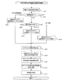
本発明の第一の実施形態に係る二次元画像生成プログラムについて、図2〜図7に基づいて説明する。
[First embodiment]
A two-dimensional image generation program according to the first embodiment of the present invention will be described with reference to FIGS.
まず、外部記憶装置16に記憶されたオブジェクト画像の各部位の二次元の画像データを読み出して、表示装置15に表示させる。そして、表示装置15に表示されたオブジェクト画像の各部位の複数種類の画像データに基づいて、ユーザが入力装置14を介して部位ごとに所望の画像データを選択する(S101:オブジェクト画像選択工程)。
First, two-dimensional image data of each part of the object image stored in the
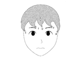
ここで、オブジェクト画像の各部位とは、例えば、図3に示すように、オブジェクトが顔である場合、顔の輪郭、眉毛、目、鼻、口等の部位である。また、二次元表示領域内で表示されたオブジェクト画像がポリゴンモデリングにより表現される場合、各部位の画像データとは、各部位の形状をポリゴンモデリングにより多角形で表現した二次元形状の画像データである。 Here, each part of the object image is a part of the face contour, eyebrows, eyes, nose, mouth or the like when the object is a face as shown in FIG. 3, for example. In addition, when the object image displayed in the two-dimensional display area is expressed by polygon modeling, the image data of each part is two-dimensional shape image data in which the shape of each part is expressed by a polygon by polygon modeling. is there.
ここで、図3の例では、各部位について1つの画像データのみを表示装置15に表示するものであるが、同じ部位であっても、複数種類の画像データを表示させて、入力装置14を介して選択させるものであって良い。
Here, in the example of FIG. 3, only one image data is displayed on the
図3の例では、表示装置15のパーツ選択領域に表示されたオブジェクト画像の各部位の複数種類の画像データから、例えば入力装置14であるマウスをクリックすることにより部位ごとに所望の画像データを選択し、選択された画像データを表示装置15の画像編集領域にドラッグして所望位置に配置して、表示装置15上で動画を作成する元となるオブジェクト画像を作成して、記憶する。
In the example of FIG. 3, desired image data for each part is obtained from a plurality of types of image data of each part of the object image displayed in the part selection area of the
尚、このS101のオブジェクト画像選択工程は必ずしも実行する必要はなく、予め決められたオブジェクト画像がある場合は、オブジェクト画像の各部位を選択することなく、次のS102のオブジェクト特徴点設定工程から開始する。 The object image selection process of S101 does not necessarily need to be executed. If there is a predetermined object image, the process starts from the next object feature point setting process of S102 without selecting each part of the object image. To do.
次に、S101のオブジェクト画像選択工程で作成されたオブジェクト画像の複数個所を特徴点としてそれぞれ設定する(S102:オブジェクト特徴点設定工程)。予め決められたオブジェクト画像がある場合は、S101のオブジェクト画像選択工程を実行することなく、予め決められたオブジェクト画像の複数個所を特徴点としてそれぞれ設定する(S102:オブジェクト特徴点設定工程)。 Next, a plurality of portions of the object image created in the object image selection step in S101 are set as feature points (S102: object feature point setting step). If there is a predetermined object image, the plurality of predetermined object images are set as feature points without executing the object image selection step of S101 (S102: object feature point setting step).
オブジェクト画像がポリゴンモデリングにより図3の例のように表現される場合、配置された各部位の画像データについての各ポリゴン(多角形)の頂点が特徴点として設定され、各ポリゴンの頂点の位置座標とテクスチャデータとが記憶される。ここで、オブジェクト画像の各部位は二次元表示領域内で表現されており、例えば、図4に示すように、各ポリゴンの頂点の位置座標は、XY座標系における位置座標として、(X,Y)で表現されるものとする。図4の例では、ポリゴンP1が4つの頂点A1,A2,A3,A4からなる四角形で表されており、ポリゴンP1の各頂点A1,A2,A3,A4の位置座標が(XA1,YA1),(XA2,YA2),(XA3,YA3),(XA4,YA4)となる。また、各ポリゴンの頂点の位置座標と共に、各ポリゴンに貼り付けるテクスチャデータ(図4の例では、頂点A1に関して(UA1,VA1))が記憶される。 When the object image is expressed by polygon modeling as in the example of FIG. 3, the vertex of each polygon (polygon) for the image data of each placed part is set as a feature point, and the position coordinates of the vertex of each polygon And texture data are stored. Here, each part of the object image is expressed in the two-dimensional display area. For example, as shown in FIG. 4, the position coordinates of the vertices of each polygon are (X, Y) as the position coordinates in the XY coordinate system. ). In the example of FIG. 4, the polygon P1 is represented by a quadrangle composed of four vertices A1, A2, A3, A4, and the position coordinates of the vertices A1, A2, A3, A4 of the polygon P1 are (XA1, YA1), (XA2, YA2), (XA3, YA3), (XA4, YA4). In addition to the position coordinates of the vertices of each polygon, texture data to be pasted to each polygon (in the example of FIG. 4, (UA1, VA1) regarding the vertex A1) is stored.
そして、表示装置15に表示されたオブジェクト画像に基づいて、複数の特徴点に共通の制御点を対応付けると共に、制御点と各特徴点との連動条件を設定する(S103:制御点設定工程)。
Then, based on the object image displayed on the
ここで、制御点は、後述するS105の特徴点操作連動情報算出工程における各制御点の操作(移動、回転、拡大、縮小)に関する制御点操作情報に基づいて、対応付けられた特徴点が連動する移動、回転、拡大、縮小を制御するものである。また、連動条件は、特徴点毎に、後述するS105の特徴点操作連動情報算出工程における各制御点の操作(移動、回転、拡大、縮小)に関する制御点操作情報に対して、対応付けられた各特徴点が連動して移動、回転、拡大、縮小する際の、移動倍率、移動方向、回転倍率、拡大倍率、縮小倍率などの条件が設定される。 Here, the control point is associated with the associated feature point based on the control point operation information regarding the operation (movement, rotation, enlargement, reduction) of each control point in the feature point operation interlocking information calculation step of S105 described later. This controls the movement, rotation, enlargement, and reduction of the image. The interlocking condition is associated with the control point operation information related to the operation (movement, rotation, enlargement, reduction) of each control point in the feature point operation interlocking information calculation step of S105 described later for each feature point. Conditions such as a movement magnification, a movement direction, a rotation magnification, an enlargement magnification, and a reduction magnification when each feature point is moved, rotated, enlarged, and reduced in conjunction with each other are set.
制御点は、表示装置15に表示されたオブジェクト画像と同じ二次元表示領域内に表示して、その位置座標を記憶するものであっても良い。
The control points may be displayed in the same two-dimensional display area as the object image displayed on the
オブジェクト画像がポリゴンモデリングにより図3の例のように表現される場合、制御点は、複数のポリゴンの頂点に共通して対応付けられるジョイントとして設定する。具体的には、図3に示すように、ジョイントはA〜Rの18箇所に設定され、図5(a)に示すように、ジョイント識別番号毎に対応付けられる頂点の頂点識別番号がデータテーブルとして記憶される。尚、図5(a)に示すデータテーブルにおいては、図4に示す各頂点(頂点識別番号)に対応する座標データ及びテクスチャデータも合わせて記載している。ここで、図3に示すオブジェクト画像の1つの部位である右側の眉毛の部分を一例として説明すると、図5(b)に示すように、複数の頂点A1,A2,A3,A4,・・・に共通のジョイントAが、複数の頂点B1,B2,B3,B4,・・・に共通のジョイントBが設定される。 When the object image is expressed by polygon modeling as in the example of FIG. 3, the control points are set as joints that are associated in common with the vertices of a plurality of polygons. Specifically, as shown in FIG. 3, 18 joints A to R are set, and as shown in FIG. 5A, vertex identification numbers of vertices associated with each joint identification number are stored in the data table. Is remembered as In the data table shown in FIG. 5A, coordinate data and texture data corresponding to each vertex (vertex identification number) shown in FIG. 4 are also described. Here, the right eyebrow portion, which is one part of the object image shown in FIG. 3, will be described as an example. As shown in FIG. 5B, a plurality of vertices A1, A2, A3, A4,. Joint A common to the plurality of vertices B1, B2, B3, B4,...
また、オブジェクト画像がポリゴンモデリングにより図3の例のように表現される場合、特徴点毎の連動条件は、後述するS105の特徴点操作連動情報算出工程における各ジョイントの操作(移動、回転、拡大、縮小)に関する制御点操作情報に対する重みづけの条件として設定する。具体的には、図5(a)に示すように、X軸方向の移動に関する倍率(移動X)、Y軸方向の移動に関する倍率(移動Y)、回転倍率(回転Z)の条件が、各頂点(頂点識別番号)に対応してデータテーブルとして設定される。 When the object image is expressed by polygon modeling as in the example of FIG. 3, the interlocking condition for each feature point is the operation (movement, rotation, enlargement) of each joint in the feature point operation interlocking information calculation step of S105 described later. , Reduction) is set as a weighting condition for control point operation information. Specifically, as shown in FIG. 5A, the magnification (movement X) for movement in the X-axis direction, the magnification (movement Y) for movement in the Y-axis direction, and the rotation magnification (rotation Z) conditions are It is set as a data table corresponding to the vertex (vertex identification number).
そして、S103の制御点設定工程で設定した制御点が操作されると(S104:YES)、制御点の操作に関する制御点操作情報及びS103の制御点設定工程で設定した連動条件に基づいて、制御点に対応付けられた各特徴点の特徴点操作連動情報を算出して記憶する(S105:特徴点操作連動情報算出工程)。 When the control point set in the control point setting step in S103 is operated (S104: YES), control is performed based on the control point operation information related to the control point operation and the interlocking conditions set in the control point setting step in S103. The feature point operation interlocking information of each feature point associated with the point is calculated and stored (S105: feature point operation interlocking information calculating step).
ここで、特徴点操作連動情報は、各制御点の操作(移動、回転、拡大、縮小)に関する制御点操作情報と、各特徴点の移動倍率、移動方向、回転倍率、拡大倍率、縮小倍率などの連動条件に基づいて算出された、対応付けられた特徴点の移動方向、移動量、回転量、拡大量、縮小量等を含むものである。そして、特徴点操作連動情報は、入力装置14を介して、表示装置15に表示されるオブジェクト画像の制御点を直接操作して入力されても良いし、予め外部記憶装置16に記憶されていても良いし、通信インターフェイス17を介して入力されるものであっても良い。
Here, the feature point operation interlocking information includes control point operation information related to operation (movement, rotation, enlargement, reduction) of each control point, movement magnification, movement direction, rotation magnification, enlargement magnification, reduction magnification, etc. of each feature point. The movement direction, the movement amount, the rotation amount, the enlargement amount, the reduction amount, and the like of the associated feature points calculated based on the interlocking conditions are included. The feature point operation linkage information may be input by directly operating the control points of the object image displayed on the
オブジェクト画像がポリゴンモデリングにより図3の例のように表現される場合、ジョイントA〜Rのそれぞれに対して、図6に示すX軸方向の移動量(移動X)、Y軸方向の移動量(移動Y)、回転量(回転Z)の制御点操作情報が入力される。ここで、X軸方向の移動量(移動X)、Y軸方向の移動量(移動Y)は、ジョイントのXY座標系における位置座標(X,Y)に対する移動量である。また、回転Zは、ジョイントのXY座標系における位置座標(X,Y)に対する回転角度であり、時計回りを正、反時計回りを負としている。 When the object image is expressed by polygon modeling as in the example of FIG. 3, the movement amount in the X-axis direction (movement X) and the movement amount in the Y-axis direction shown in FIG. Control point operation information of movement Y) and rotation amount (rotation Z) is input. Here, the movement amount in the X-axis direction (movement X) and the movement amount in the Y-axis direction (movement Y) are movement amounts with respect to the position coordinates (X, Y) of the joint in the XY coordinate system. The rotation Z is a rotation angle with respect to the position coordinate (X, Y) of the joint in the XY coordinate system, and the clockwise direction is positive and the counterclockwise direction is negative.
そして、図6に示す制御点操作情報と、図5(a)に示す連動条件(重みづけ)に基づいて、ジョイントA〜Rのそれぞれに対応付けられた各頂点の特徴点操作連動情報、即ち、X軸方向の移動量(移動X)、Y軸方向の移動量(移動Y)、回転量(回転Z)が算出される。 Based on the control point operation information shown in FIG. 6 and the interlocking condition (weighting) shown in FIG. 5A, the feature point operation interlocking information of each vertex associated with each of the joints A to R, that is, The amount of movement in the X-axis direction (movement X), the amount of movement in the Y-axis direction (movement Y), and the amount of rotation (rotation Z) are calculated.
ここで、特徴点操作連動情報に、各特徴点が移動位置まで移動する過程において補完する補完位置が含まれていても良い。この場合、制御点を任意に操作することにより、オブジェクト画像を現在の状態から別の状態に変化するまでの二次元の動画をリアルタイムに生成する際に、補完位置で調整することにより、各頂点が現在の位置座標から移動位置まで移動する際に不自然にならず、画像生成効率をより向上させることができる。 Here, the feature point operation interlocking information may include a complementary position that is complemented in the process in which each feature point moves to the movement position. In this case, by arbitrarily operating the control point, when generating a two-dimensional video in real time until the object image changes from the current state to another state, by adjusting at the complementary position, each vertex Is not unnatural when moving from the current position coordinates to the moving position, and the image generation efficiency can be further improved.
尚、制御点が操作されない場合は(S104:NO)、後述するS108の工程において、画像生成を終了するかどうかの判断が行われる。 When the control point is not operated (S104: NO), it is determined whether or not to end the image generation in the process of S108 described later.
そして、S105の特徴点操作連動情報算出工程で算出した特徴点操作連動情報に従って、各特徴点を制御点に連動させることにより変化したオブジェクト画像を表示周期毎に生成して(S106:画像表示制御工程)、表示装置15に表示する(S107:画像表示制御工程)。 Then, according to the feature point operation interlocking information calculated in the feature point operation interlocking information calculating step of S105, an object image changed by interlocking each feature point with the control point is generated for each display cycle (S106: image display control). Step) and display on the display device 15 (S107: image display control step).
例えば、各特徴点について、特徴点操作連動情報に従って現在の位置座標から算出された移動位置まで変化する過程を、表示周期毎に分割し、表示周期毎にオブジェクト画像を生成して、表示装置15に表示する。
For example, for each feature point, the process of changing from the current position coordinates to the movement position calculated according to the feature point operation interlocking information is divided for each display period, and an object image is generated for each display period, and the
ここで、表示周期はフレームレートにより算出され、表示周期毎のオブジェクト画像を1フレームとして生成する。 Here, the display cycle is calculated from the frame rate, and an object image for each display cycle is generated as one frame.
オブジェクト画像がポリゴンモデリングにより図3の例のように表現される場合、S105の特徴点操作連動情報算出工程で算出した特徴点操作連動情報に従って、各頂点をジョイントA〜Rに連動させることにより変化したオブジェクト画像を表示周期毎に生成して、表示装置15に表示し、図7の左側に示すオブジェクト画像から右側に示すオブジェクト画像に変化する動画が表示される。
When the object image is represented by polygon modeling as in the example of FIG. 3, the change is made by linking each vertex to the joints A to R according to the feature point operation interlocking information calculated in the feature point operation interlocking information calculating step of S105. The generated object image is generated for each display period and displayed on the
最後に、画像生成を終了するかどうかの判断を行う(S108)。例えば、画像生成を終了するかどうかを、ユーザが入力装置12を介して選択するようにして良い。
Finally, it is determined whether or not to end image generation (S108). For example, the user may select via the
S108において、画像生成を終了しないと判断した場合(S108:NO)、S104の工程に、処理を進める。
一方、S108において、画像生成を終了すると判断した場合(S108:YES)、二次元画像生成プログラムの処理を終了する。
If it is determined in S108 that the image generation is not finished (S108: NO), the process proceeds to the process of S104.
On the other hand, when it is determined in S108 that the image generation is to be ended (S108: YES), the processing of the two-dimensional image generation program is ended.
このように、第一の実施形態に係る二次元画像生成プログラム、二次元画像生成プログラムを記録した記録媒体及び二次元画像生成システムは、二次元表示領域内に表現されるオブジェクト画像について、特徴点を設定し、複数の特徴点に対応付けられた共通の制御点を設定している(S101〜S103)。次に、制御点を操作する制御点操作情報及び制御点と各特徴点との連動条件に基づいて、制御点に対応付けられた特徴点の特徴点操作連動情報を算出している(S104〜S105)。そして、特徴点操作連動情報に従って、各特徴点を制御点に連動させることにより変化したオブジェクト画像を表示周期毎に生成して、動画として表示している(S106〜S107)。 As described above, the two-dimensional image generation program according to the first embodiment, the recording medium on which the two-dimensional image generation program is recorded, and the two-dimensional image generation system are feature points regarding the object image represented in the two-dimensional display area. And common control points associated with a plurality of feature points are set (S101 to S103). Next, based on the control point operation information for operating the control point and the interlocking condition between the control point and each feature point, the feature point operation interlocking information of the feature point associated with the control point is calculated (S104-). S105). Then, according to the feature point operation linkage information, an object image changed by linking each feature point to the control point is generated for each display period and displayed as a moving image (S106 to S107).
従って、事前に現在の状態から別の状態に変化するまでのオブジェクト画像について事前に登録することなく、制御点を任意に操作することにより、オブジェクト画像を現在の状態から別の状態に変化するまでの二次元の動画をリアルタイムに生成することができ、オブジェクト画像を任意の様々な状態に変化させる二次元の動画を生成することができる。また、特徴点と制御点のみを登録しておけば、制御点を操作するだけで、オブジェクト画像を現在の状態から別の状態に変化するまでの二次元の動画をリアルタイムに生成することができ、事前に設定するデータ容量を減らして、動画の生成効率を向上させることができる。二次元仮想空間において表現された画像であるオブジェクトについて、制御点を操作することにより、制御点に対応付けられた頂点についての移動する先である移動位置を含めた頂点移動情報を算出して、オブジェクトを編集している。従って、オブジェクトを現在の状態から変形するまでの二次元の画像データをアニメーション画像として容易に編集することができ、編集効率を向上させることができる。また、オブジェクトについて変形する形を事前に登録する必要なく、オブジェクトを任意の形に編集することができる。 Therefore, until the object image is changed from the current state to another state by arbitrarily operating the control point without previously registering the object image until the state is changed from the current state to another state in advance. The two-dimensional moving image can be generated in real time, and the two-dimensional moving image that changes the object image to any of various states can be generated. In addition, if only feature points and control points are registered, a two-dimensional movie can be generated in real time until the object image changes from the current state to another state simply by operating the control points. It is possible to reduce the data capacity set in advance and improve the generation efficiency of moving images. For an object that is an image expressed in a two-dimensional virtual space, by operating a control point, vertex movement information including a movement position that is a movement destination for the vertex associated with the control point is calculated, You are editing an object. Therefore, two-dimensional image data from when the object is deformed to the current state can be easily edited as an animation image, and editing efficiency can be improved. Further, it is possible to edit the object into an arbitrary shape without having to register in advance a shape to deform the object.
また、オブジェクト画像は、複数種類の画像データから各部位が選択されて二次元表示領域内に表現されている(S101)。 The object image is represented in the two-dimensional display area by selecting each part from a plurality of types of image data (S101).
従って、オブジェクト画像の各部位を複数種類の画像データから選択可能にしていることから、ユーザが選択した様々なオブジェクト画像に基づいて、二次元の動画を生成することができ、動画を生成する際の選択の幅が広がる。 Accordingly, since each part of the object image can be selected from a plurality of types of image data, a two-dimensional moving image can be generated based on various object images selected by the user. The range of choices expands.
[第二の実施形態]
本発明の第二の実施形態に係る二次元画像生成プログラムについて、図8〜図11に基づいて説明する。尚、本発明の第二の実施形態に係る二次元画像生成プログラムの説明において、上述の本発明の第一の実施形態に係る二次元画像生成プログラムと同じ工程については、同じ工程であることを示して、その説明を省略する。
[Second Embodiment]
A two-dimensional image generation program according to the second embodiment of the present invention will be described with reference to FIGS. In the description of the two-dimensional image generation program according to the second embodiment of the present invention, the same steps as those of the above-described two-dimensional image generation program according to the first embodiment of the present invention are the same steps. The description is omitted.
まず、外部記憶装置16に記憶されたオブジェクト画像の各部位の二次元の画像データを読み出して、表示装置15に表示させる。そして、表示装置15に表示されたオブジェクト画像の各部位の複数種類の画像データに基づいて、ユーザが入力装置14を介して部位ごとに所望の画像データを選択する(S201:オブジェクト画像選択工程)。この工程は、上述の本発明の第一の実施形態に係る二次元画像生成プログラムにおけるS101のオブジェクト画像選択工程と同じであり、その説明を省略する。
First, two-dimensional image data of each part of the object image stored in the
尚、このS201のオブジェクト画像選択工程は必ずしも実行する必要はなく、予め決められたオブジェクト画像がある場合は、オブジェクト画像の各部位を選択することなく、次のS202のオブジェクト特徴点設定工程から開始する。 The object image selection process in S201 is not necessarily executed. If there is a predetermined object image, the process starts from the next object feature point setting process in S202 without selecting each part of the object image. To do.
次に、S201のオブジェクト画像選択工程で作成されたオブジェクト画像の複数個所を特徴点としてそれぞれ設定する(S202:オブジェクト特徴点設定工程)。予め決められたオブジェクト画像がある場合は、S201のオブジェクト画像選択工程を実行することなく、予め決められたオブジェクト画像の複数個所を特徴点としてそれぞれ設定する(S202:オブジェクト特徴点設定工程)。この工程は、上述の本発明の第一の実施形態に係る二次元画像生成プログラムにおけるS102のオブジェクト特徴点設定工程と同じであり、その説明を省略する。 Next, a plurality of locations in the object image created in the object image selection step in S201 are set as feature points (S202: object feature point setting step). When there is a predetermined object image, a plurality of predetermined object images are set as feature points without executing the object image selection step of S201 (S202: object feature point setting step). This step is the same as the object feature point setting step of S102 in the two-dimensional image generation program according to the first embodiment of the present invention described above, and a description thereof will be omitted.
そして、表示装置15に表示されたオブジェクト画像に基づいて、複数の特徴点に共通の制御点を対応付けると共に、制御点と各特徴点との連動条件を設定する(S203:制御点設定工程)。この工程は、上述の本発明の第一の実施形態に係る二次元画像生成プログラムにおけるS103の制御点設定工程と同じであり、その説明を省略する。
Then, based on the object image displayed on the
次に、S203で設定した複数の制御点に共通の上位の制御点を対応付けると共に、上位の制御点と制御点との上位連動条件を設定する(S204:上位制御点設定工程)。上位の制御点は、1つの階層だけでなく、複数の上位の制御点が対応付けられた更に上位の制御点を設定して、複数階層設定しても良い。また、上位の制御点は1つだけでなく、複数設定して良い。 Next, a common upper control point is associated with the plurality of control points set in S203, and an upper interlocking condition between the upper control point and the control point is set (S204: upper control point setting step). The upper control point may be set not only in one layer but also in a plurality of layers by setting a higher control point associated with a plurality of upper control points. Further, not only one upper control point but also a plurality of control points may be set.
オブジェクト画像がポリゴンモデリングにより図9の例のように表現される場合、5箇所に設定された複数のジョイントS〜Wが対応付けられた上位ジョイントXが設定される。これらのジョイントS〜Wと上位ジョイントXの階層構造は、図10に示すとおりである。また、図9に示す例において、ジョイントとジョイントに対応付けられる頂点の関係と、上位ジョイントと上位ジョイントに対応付けられるジョイントの関係との関係は、図11に示すとおりである。また、図9に示す例において、オブジェクト画像は二次元表示領域内で表現されており、XY座標系における各頂点の座標データ及びテクスチャデータは図11に示すように設定されている。更に、図9に示す例において、各頂点の連動条件は、図11に示すように設定されている。 When the object image is expressed by polygon modeling as in the example of FIG. 9, upper joints X in which a plurality of joints SW are set in five locations are set. The hierarchical structure of these joints SW and the upper joint X is as shown in FIG. In the example shown in FIG. 9, the relationship between the joint and the vertex relationship associated with the joint and the relationship between the upper joint and the upper joint are as shown in FIG. In the example shown in FIG. 9, the object image is expressed in the two-dimensional display area, and the coordinate data and texture data of each vertex in the XY coordinate system are set as shown in FIG. Further, in the example shown in FIG. 9, the interlocking condition of each vertex is set as shown in FIG.
更に、上位の制御点には、対応付けられた各制御点の上位連動条件が予め設定される。上位連動条件として、上位の制御点の操作(移動、回転、拡大、縮小)に関する上位制御点操作情報に対して、対応付けられた制御点が連動する操作(移動、回転、拡大、縮小)に関する条件の他、操作の時間の条件が設定される。 Furthermore, the upper interlocking conditions of the associated control points are set in advance for the upper control points. As the upper link condition, the operation (movement, rotation, enlargement, reduction) in which the associated control point is linked to the upper control point operation information related to the operation (movement, rotation, enlargement, reduction) of the upper control point. In addition to the conditions, an operation time condition is set.
ここで、オブジェクト画像がポリゴンモデリングにより図9の例のように表現される場合、対応付けられたジョイントが連動する操作(移動、回転、拡大、縮小)に関する条件と、操作の時間の条件について設定されており、各ジョイントS〜Wに対する上位連動条件が図11に示すように設定される。図11では、操作の時間の条件として、ジョイントの操作を開始するフレーム(フレーム識別番号)を指定している。図11の例では、ジョイントS,T,U,VがフレームF1でジョイントの操作を開始し、ジョイントWのみがフレームF2でジョイントの操作を開始する条件で設定されている。 Here, when the object image is represented by polygon modeling as shown in the example of FIG. 9, the conditions related to the operation (movement, rotation, enlargement, reduction) with which the associated joint is linked and the operation time condition are set. The upper interlocking conditions for the joints S to W are set as shown in FIG. In FIG. 11, a frame (frame identification number) at which the joint operation is started is specified as a condition for the operation time. In the example of FIG. 11, the joints S, T, U, and V are set on the condition that the joint operation is started in the frame F1 and only the joint W is started in the frame F2.
また、図9の例において、ジョイントS〜VとジョイントWの動きに時間差(タイムラグ)が生じるようなエクスプレッションの一例を示す。
ここで、ジョイントS〜Vの要素をhair_joint1、ジョイントWの要素をhair_joint2と定義する。
また、上位ジョイントXの要素をhair_X_prntと定義する。
Moreover, in the example of FIG. 9, an example of an expression in which a time difference (time lag) occurs in the movement of the joints S to V and the joint W is shown.
Here, the elements of the joints S to V are defined as hair_joint1, and the element of the joint W is defined as hair_joint2.
Further, the element of the upper joint X is defined as hair_X_prnt.
そして、エクスプレッションを下記のように定義する。
int $time=`currentTime‐q`;
//タイムスライダー内でカーソルがあるフレーム、時間
$timeへ代入
ここで、タイムスライダーとは、オブジェクトの編集結果として予め設定する時間(即ち、アニメーション画像を編集する時間)を意味するものである。
vector $valueOut;
//ベクトル 座標
int $timeLag_step;
//タイムラグさせる値、フレーム
ここで、タイムラグとは、任意に指定することができる値であって、図9に示すオブジェクト画像においては、ジョイントWがジョイントS〜Vから遅れて動くまでの時間のことを意味し、図11の上位連動条件で設定したフレームF1とフレームF2との間の時間である。
int $timeLag_hair_joint1;
//タイムラグさせる値、フレーム
float $power_1_1st;
//上位ジョイントXがジョイントS〜Vに与える回転値にかける値、倍率
float $power_1_2nd;
//上位ジョイントXがジョイントWに与える回転値にかける値、倍率
$timeLag_step=`getAttr−t $time hair_X_prnt.timeLag_step;
//タイムスライダー内でカーソルがあるフレームのときの上位ジョイントXのtimeLag_stepにある値を$timeLag_stepに代入する。
$timeLag_ hair_joint1=`getAttr−t $time hair_X_prnt.timeLag_ hair_joint1;
//タイムスライダー内でカーソルがあるフレームのときの上位ジョイントXのtimeLag_hair_joint1にある値を$timeLag_hair_joint1に代入する。
$ power_1_1st=`getAttr−t $time hair_X_prnt. power_1_1st;
//タイムスライダー内でカーソルがあるフレームのときの上位ジョイントXのpower_1_1stにある値を$ power_1_1stに代入する。
$ power_1_2nd=`getAttr−t $time hair_X_prnt. power_1_2nd;
//タイムスライダー内でカーソルがあるフレームのときの上位ジョイントXのpower_1_2ndにある値を$ power_1_2ndに代入する。
And define the expression as follows.
int $ time = `currentTime-q`;
// Frame where the cursor is in the time slider, time
Here, the time slider means a time set in advance as an object editing result (that is, a time for editing an animation image).
vector $ valueOut;
// vector coordinates
int $ timeLag_step;
// Value to be time lag, frame Here, the time lag is a value that can be arbitrarily specified, and in the object image shown in FIG. 9, the time until the joint W moves behind the joints S to V is delayed. This is the time between the frame F1 and the frame F2 set in the upper interlocking condition of FIG.
int $ timeLag_hair_joint1;
// Time lag value, frame
float $ power_1_1st;
// Value to be applied to rotation value given to joints S to V by upper joint X, magnification
float $ power_1_2nd;
// Value applied to the rotation value given to the joint W by the upper joint X, magnification
$ timeLag_step = `getAttr-t $ time hair_X_prnt.timeLag_step;
// Substitute the value in timeLag_step of the upper joint X at the frame where the cursor is in the time slider into $ timeLag_step.
$ timeLag_ hair_joint1 = `getAttr-t $ time hair_X_prnt.timeLag_ hair_joint1;
// Substitute the value in timeLag_hair_joint1 of the upper joint X in the time slider in the time slider in $ timeLag_hair_joint1.
$ power_1_1st = `getAttr-t $ time hair_X_prnt. power_1_1st;
// Substitute the value in power_1_1st of the upper joint X at the frame where the cursor is in the time slider for $ power_1_1st.
$ power_1_2nd = `getAttr-t $ time hair_X_prnt. power_1_2nd;
// Substitute the value in power_1_2nd of the upper joint X at the frame where the cursor is in the time slider for $ power_1_2nd.
そして、計算式は下記の通りとなる。
//hair_joint1
$valueOut=` getAttr−t( $time−$timeLag_ hair_jointS) hair_X_prnt.r`;
$valueOut=$valueOut * $power_1_1st;
hair_joint1.rotateX=($valueOut.x);
hair_joint1.rotateY=($valueOut.y);
hair_joint1.rotateZ=($valueOut.z);
//タイムスライダー内でカーソルが有るフレームから$timeLag_ hair_joint1に代入された値を引いたフレームの時のhair_X_prntの回転XYZを$valueOutへ代入。
//$valueOutに代入された値に$power_1_1stに代入された値を代入。
//hair_joint1の回転 XYZへ、$valueOutに代入された値を代入。
//hair_joint2
$valueOut=` getAttr−t( $time−$timeLag_ hair_joint1−$timeLag_ step) hair_X_prnt.r`;
$valueOut=$valueOut * $power_1_2nd;
hair_joint2.rotateX=($valueOut.x);
hair_joint2.rotateY=($valueOut.y);
hair_joint2.rotateZ=($valueOut.z);
//タイムスライダー内でカーソルが有るフレームから$timeLag_ hair_joint1に代入された値を引いて、更に$timeLag_ stepで代入された値を引いたフレームの時のhair_X_prntの回転XYZを$valueOutへ代入。
//$valueOutに代入された値に$power_1_2ndに代入された値を代入。
//hair_joint2の回転XYZへ、$valueOutに代入された値を代入。
And the calculation formula is as follows.
// hair_joint1
$ valueOut = `getAttr-t ($ time- $ timeLag_ hair_jointS) hair_X_prnt.r`;
$ valueOut = $ valueOut * $ power_1_1st;
hair_joint1.rotateX = ($ valueOut.x);
hair_joint1.rotateY = ($ valueOut.y);
hair_joint1.rotateZ = ($ valueOut.z);
// Substitute the XYZ rotation of hair_X_prnt for the frame obtained by subtracting the value assigned to $ timeLag_hair_joint1 from the frame where the cursor is located in the time slider into $ valueOut.
// Assign the value assigned to $ power_1_1st to the value assigned to $ valueOut.
// Rotate hair_joint1 Assign the value assigned to $ valueOut to XYZ.
// hair_joint2
$ valueOut = `getAttr-t ($ time- $ timeLag_ hair_joint1- $ timeLag_ step) hair_X_prnt.r`;
$ valueOut = $ valueOut * $ power_1_2nd;
hair_joint2.rotateX = ($ valueOut.x);
hair_joint2.rotateY = ($ valueOut.y);
hair_joint2.rotateZ = ($ valueOut.z);
// Subtract the value assigned to $ timeLag_hair_joint1 from the frame where the cursor is located in the time slider, and then substitute the rotation XYZ of hair_X_prnt to $ valueOut for the frame obtained by subtracting the value assigned in $ timeLag_step.
// Assign the value assigned to $ power_1_2nd to the value assigned to $ valueOut.
// The value assigned to $ valueOut is assigned to the rotation XYZ of hair_joint2.
以上のエクスプレッションをコンピュータで実行し、予め設定された上位ジョイントXを動かすことにより、ジョイントS〜Vより指定されたフレーム分送れてジョイントWが動いているように見える。 When the above expression is executed by the computer and the upper joint X set in advance is moved, it seems that the joint W is moved by sending the designated frame from the joints S to V.
そして、S204の上位制御点設定工程で設定した上位制御点が操作されると(S205:YES)、上位制御点の操作に関する上位制御点操作情報及びS204の上位制御点設定工程で設定した上位連動条件に基づいて、上位制御点に対応付けられた各制御点の制御点操作連動情報を算出して記憶する(S206:制御点操作連動情報算出工程)。 When the upper control point set in the upper control point setting step in S204 is operated (S205: YES), the upper control point operation information related to the operation of the upper control point and the upper linkage set in the upper control point setting step in S204. Based on the condition, the control point operation interlocking information of each control point associated with the higher control point is calculated and stored (S206: control point operation interlocking information calculating step).
ここで、制御点操作連動情報は、上位制御点の操作(移動、回転、拡大、縮小)に関する上位制御点操作情報と、各制御点の上位連動条件に基づいて算出された、対応付けられた制御点の移動方向、移動量、回転量、拡大量、縮小量等を含むものである。そして、制御点操作連動情報は、入力装置14を介して、表示装置15に表示されるオブジェクト画像の上位制御点を直接操作して入力されても良いし、予め外部記憶装置16に記憶されていても良いし、通信インターフェイス17を介して入力されるものであっても良い。
Here, the control point operation linkage information is associated with the upper control point operation information related to the operation (movement, rotation, enlargement, reduction) of the upper control point and the upper linkage condition of each control point. This includes the movement direction, movement amount, rotation amount, enlargement amount, reduction amount, etc. of the control points. The control point operation linkage information may be input by directly operating the upper control point of the object image displayed on the
尚、上位制御点が操作されない場合は(S205:NO)、後述するS210の工程において、画像生成を終了するかどうかの判断が行われる。 If the upper control point is not operated (S205: NO), it is determined in step S210 to be described later whether image generation is to be terminated.
そして、S206の制御点操作連動情報算出工程で算出した制御点の制御点操作連動情報とS203の制御点設定工程で設定した連動条件に基づいて、制御点に対応付けられた各特徴点の特徴点操作連動情報を算出して記憶する(S207:特徴点操作連動情報算出工程)。 Then, based on the control point operation interlocking information of the control point calculated in the control point operation interlocking information calculating step of S206 and the interlocking condition set in the control point setting step of S203, the feature of each feature point associated with the control point Point operation interlocking information is calculated and stored (S207: feature point operation interlocking information calculating step).
ここで、特徴点操作連動情報は、各制御点の操作(移動、回転、拡大、縮小)に関する制御点操作情報と、各特徴点の移動倍率、移動方向、回転倍率、拡大倍率、縮小倍率などの連動条件に基づいて算出された、対応付けられた特徴点の移動方向、移動量、回転量、拡大量、縮小量等を含むものである。 Here, the feature point operation interlocking information includes control point operation information related to operation (movement, rotation, enlargement, reduction) of each control point, movement magnification, movement direction, rotation magnification, enlargement magnification, reduction magnification, etc. of each feature point. The movement direction, the movement amount, the rotation amount, the enlargement amount, the reduction amount, and the like of the associated feature points calculated based on the interlocking conditions are included.
尚、特徴点操作連動情報に、各特徴点が移動位置まで移動する過程において補完する補完位置が含まれていても良い。この場合、制御点を任意に操作することにより、オブジェクト画像を現在の状態から別の状態に変化するまでの二次元の動画をリアルタイムに生成する際に、補完位置で調整することにより、各頂点が現在の位置座標から移動位置まで移動する際に不自然にならず、画像生成効率をより向上させることができる。 It should be noted that the feature point operation linkage information may include a complementary position that is complemented in the process in which each feature point moves to the movement position. In this case, by arbitrarily operating the control point, when generating a two-dimensional video in real time until the object image changes from the current state to another state, by adjusting at the complementary position, each vertex Is not unnatural when moving from the current position coordinates to the moving position, and the image generation efficiency can be further improved.
そして、S207の特徴点操作連動情報算出工程で算出した特徴点操作連動情報に従って、各特徴点を制御点に連動させることにより変化したオブジェクト画像を表示周期毎に生成して(S208:画像表示制御工程)、表示装置15に表示する(S209:画像表示制御工程)。この工程は、上述の本発明の第一の実施形態に係る二次元画像生成プログラムにおけるS106〜107の画像表示制御工程と同じであり、その説明を省略する。 Then, according to the feature point operation interlocking information calculated in the feature point operation interlocking information calculating step of S207, an object image changed by interlocking each feature point with the control point is generated for each display cycle (S208: image display control). Step) and display on the display device 15 (S209: image display control step). This process is the same as the image display control process of S106 to S107 in the two-dimensional image generation program according to the first embodiment of the present invention described above, and a description thereof will be omitted.
最後に、画像生成を終了するかどうかの判断を行う(S210)。例えば、画像生成を終了するかどうかを、ユーザが入力装置12を介して選択するようにして良い。
Finally, it is determined whether or not to end image generation (S210). For example, the user may select via the
S210において、画像生成を終了しないと判断した場合(S210:NO)、S205の工程に、処理を進める。
一方、S210において、画像生成を終了すると判断した場合(S210:YES)、二次元画像生成プログラムの処理を終了する。
In S210, when it is determined that the image generation is not finished (S210: NO), the process proceeds to step S205.
On the other hand, when it is determined in S210 that the image generation is to be ended (S210: YES), the processing of the two-dimensional image generation program is ended.
このように、第二の実施形態に係る二次元画像生成プログラム、二次元画像生成プログラムを記録した記録媒体及び二次元画像生成システムは、二次元表示領域内に表現されるオブジェクト画像について、特徴点を設定し、複数の特徴点に対応付けられた共通の制御点を設定している。更に、複数の制御点に対応付けた上位の制御点を設定している。次に、上位の制御点を操作する上位制御点操作情報及び上位の制御点と各制御点との上位連動条件に基づいて算出した制御点操作情報と連動情報に基づいて、制御点に対応付けられた特徴点の特徴点操作連動情報を算出している。そして、特徴点操作連動情報に従って、各特徴点を制御点に連動させることにより変化したオブジェクト画像を表示周期毎に生成して、動画として表示している。 As described above, the two-dimensional image generation program according to the second embodiment, the recording medium on which the two-dimensional image generation program is recorded, and the two-dimensional image generation system include feature points for object images represented in the two-dimensional display area. And a common control point associated with a plurality of feature points is set. Furthermore, upper control points associated with a plurality of control points are set. Next, it is associated with the control point based on the upper control point operation information for operating the upper control point and the control point operation information calculated based on the upper link condition between the upper control point and each control point and the link information. The feature point operation linkage information of the obtained feature point is calculated. Then, according to the feature point operation linkage information, an object image changed by linking each feature point to the control point is generated for each display period and displayed as a moving image.
従って、事前に現在の状態から別の状態に変化するまでのオブジェクト画像について事前に登録することなく、上位の制御点を任意に操作することにより、対応付けられた複数の制御点の制御点操作情報をまとめて算出し、それに基づいて、オブジェクト画像を現在の状態から別の状態に変化するまでの二次元の動画をリアルタイムに生成することができ、オブジェクト画像を任意の様々な状態に変化させる二次元の動画を生成することができる。また、特徴点と制御点と上位の制御点のみを登録しておけば、上位の制御点を含めた制御点を操作するだけで、オブジェクト画像を現在の状態から別の状態に変化するまでの二次元の動画をリアルタイムに生成することができ、事前に設定するデータ容量を減らして、動画の生成効率をより向上させることができる。 Therefore, the control point operation of a plurality of associated control points can be performed by arbitrarily operating the upper control points without previously registering the object image until the current state changes from the current state to another state. Based on the information, it is possible to generate a two-dimensional video in real time until the object image changes from the current state to another state based on the information, and change the object image to any of various states. A two-dimensional video can be generated. Also, if only the feature points, control points, and higher control points are registered, the object image can be changed from the current state to another state only by operating the control points including the higher control points. A two-dimensional moving image can be generated in real time, and the data volume set in advance can be reduced, and the moving image generation efficiency can be further improved.
また、上位連動条件として、例えば、上位の制御点に対応付けられた制御点を操作するフレームに関する情報が含まれ、これにより、上位の制御点に対応付けられた制御点の操作を時間差で実行することが可能となり、制御点の操作をより幅広く設定して、オブジェクト画像を変化の態様をより細かく表現することができ、画像生成効率をより向上させることができる。 In addition, as an upper interlocking condition, for example, information on a frame for operating a control point associated with an upper control point is included, and thereby, operation of a control point associated with an upper control point is executed with a time difference. This makes it possible to set the operation of the control points more broadly, to express the object image in a more detailed manner, and to further improve the image generation efficiency.
[第三の実施形態]
本発明の第三の実施形態に係る二次元画像生成プログラムについて、図3、図12〜図14に基づいて説明する。尚、本発明の第三の実施形態に係る二次元画像生成プログラムの説明において、上述の本発明の第一の実施形態に係る二次元画像生成プログラムと同じ工程については、同じ工程であることを示して、その説明を省略する。
[Third embodiment]
A two-dimensional image generation program according to the third embodiment of the present invention will be described with reference to FIGS. 3 and 12 to 14. In the description of the two-dimensional image generation program according to the third embodiment of the present invention, the same steps as those of the above-described two-dimensional image generation program according to the first embodiment of the present invention are the same steps. The description is omitted.
まず、外部記憶装置16に記憶されたオブジェクト画像の各部位の二次元の画像データを読み出して、表示装置15に表示させる。そして、表示装置15に表示されたオブジェクト画像の各部位の複数種類の画像データに基づいて、ユーザが入力装置14を介して部位ごとに所望の画像データを選択する(S301:オブジェクト画像選択工程)。この工程は、上述の本発明の第一の実施形態に係る二次元画像生成プログラムにおけるS101のオブジェクト画像選択工程と同じであり、その説明を省略する。
First, two-dimensional image data of each part of the object image stored in the
尚、このS301のオブジェクト画像選択工程は必ずしも実行する必要はなく、予め各部位の画像データが決められたオブジェクト画像がある場合は、オブジェクト画像の各部位を選択することなく、次のS302のオブジェクト特徴点設定工程から開始する。 Note that the object image selection step of S301 is not necessarily executed. If there is an object image for which image data of each part is determined in advance, the next object of S302 is selected without selecting each part of the object image. Start from the feature point setting process.
次に、S301のオブジェクト画像選択工程で作成されたオブジェクト画像の複数個所を特徴点としてそれぞれ設定する(S302:オブジェクト特徴点設定工程)。予め各部位の画像データが決められたオブジェクト画像がある場合は、S301のオブジェクト画像選択工程を実行することなく、予め決められたオブジェクト画像の複数個所を特徴点としてそれぞれ設定する(S302:オブジェクト特徴点設定工程)。この工程は、上述の本発明の第一の実施形態に係る二次元画像生成プログラムにおけるS102のオブジェクト特徴点設定工程と同じであり、その説明を省略する。 Next, a plurality of portions of the object image created in the object image selection step in S301 are set as feature points (S302: object feature point setting step). If there is an object image for which image data of each part has been determined in advance, a plurality of predetermined positions in the object image are set as feature points without executing the object image selection step in S301 (S302: Object feature). Point setting process). This step is the same as the object feature point setting step of S102 in the two-dimensional image generation program according to the first embodiment of the present invention described above, and a description thereof will be omitted.
そして、表示装置15に表示されたオブジェクト画像に基づいて、複数の特徴点に共通の制御点を対応付けると共に、制御点と各特徴点との連動条件を設定する(S303:制御点設定工程)。この工程は、上述の本発明の第一の実施形態に係る二次元画像生成プログラムにおけるS103の制御点設定工程と同じであり、その説明を省略する。
Then, based on the object image displayed on the
次に、表示装置15に表示されたオブジェクト画像に対して、部位の画像データが変更されたかどうか判断する(S304:オブジェクト画像選択工程)。尚、オブジェクト画像の所定の部位を変更するかどうかを、ユーザが入力装置12を介して選択した後、所定の部位の画像データを変更するようにして良い。部位の画像データが変更されると(S304:YES)、変更した部位の特徴点を設定する(S305:オブジェクト画像選択工程)。
Next, it is determined whether the image data of the part has been changed with respect to the object image displayed on the display device 15 (S304: object image selection step). It should be noted that after the user selects via the
部位の画像データの変更は、例えば、図3に示すように、画像編集領域で表示されるオブジェクト画像の変更を希望する部位の画像データを削除し、次に、表示装置15のパーツ選択領域に表示されたオブジェクト画像の各部位の複数種類の画像データから、例えば入力装置14であるマウスをクリックすることにより、変更を希望する部位の所望の画像データを選択し、選択された画像データを表示装置15の画像編集領域にドラッグして所望位置に配置して、表示装置15上で動画を作成する元となるオブジェクト画像を変更して、変更した部位の特徴点を設定する。この際、変更後の部位の特徴点に関しては、変更前と同じ部位の特徴点に対応付けられた制御点に対応付けられるとともに、変更前と同じ連動条件が設定される。
For example, as shown in FIG. 3, the image data of the part is deleted by deleting the image data of the part desired to change the object image displayed in the image editing area, and then in the part selection area of the
例えば、図3に示すS301のオブジェクト画像選択工程で作成して記憶したオブジェクト画像の眉毛、目、鼻、口の各部位に対して、異なる画像を配置してオブジェクトを変更することにより、図13の左側から右側に示すオブジェクト画像に変更し、図14に示すように、変更後の各部位の頂点の位置座標(座標データ)及びテクスチャデータを設定する。尚、変更前の座標データ及びテクスチャデータは図4に示す通りである。この際、変更前と同じ部位を表現する変更後の頂点に関して変更前の頂点に対応付けられたジョイントA〜Rに対応付けられると共に、変更前と同じ連動条件が設定される。尚、変更前のジョイントとジョイントに対応付けられる頂点の関係と、各頂点の連動条件は図5(a)に示す通りである。 For example, by changing the object by arranging different images for the eyebrows, eyes, nose, and mouth parts of the object image created and stored in the object image selection step of S301 shown in FIG. The object image shown in FIG. 14 is changed from the left side to the right side, and the position coordinates (coordinate data) and texture data of the vertices of each part after the change are set as shown in FIG. The coordinate data and texture data before the change are as shown in FIG. At this time, the changed vertex expressing the same part as before the change is associated with the joints A to R associated with the vertex before the change, and the same interlocking condition as before the change is set. The relationship between the joints before the change and the vertices associated with the joints and the interlocking conditions of the vertices are as shown in FIG.
一方、表示装置15に表示されたオブジェクト画像に対して、部位の画像データが変更されない場合(S304:NO)、S306の工程に進む。 On the other hand, when the image data of the part is not changed with respect to the object image displayed on the display device 15 (S304: NO), the process proceeds to S306.
そして、S303の制御点設定工程で設定した制御点が操作されると(S306:YES)、制御点の操作に関する制御点操作情報及びS303の制御点設定工程で設定した連動条件に基づいて、制御点に対応付けられた各特徴点の特徴点操作連動情報を算出して記憶する(S307:特徴点操作連動情報算出工程)。この工程は、上述の本発明の第一の実施形態に係る二次元画像生成プログラムにおけるS105の特徴点操作連動情報算出工程と同じであり、その説明を省略する。 When the control point set in the control point setting step in S303 is operated (S306: YES), control is performed based on the control point operation information related to the control point operation and the interlocking condition set in the control point setting step in S303. The feature point operation interlocking information of each feature point associated with the point is calculated and stored (S307: feature point operation interlocking information calculating step). This step is the same as the feature point operation interlocking information calculation step of S105 in the two-dimensional image generation program according to the first embodiment of the present invention described above, and a description thereof will be omitted.
尚、制御点が操作されない場合は(S306:NO)、後述するS310の工程において、画像生成を終了するかどうかの判断が行われる。 When the control point is not operated (S306: NO), it is determined whether or not to end the image generation in the process of S310 described later.
そして、S307の特徴点操作連動情報算出工程で算出した特徴点操作連動情報に従って、各特徴点を制御点に連動させることにより変化したオブジェクト画像を表示周期毎に生成して(S308:画像表示制御工程)、表示装置15に表示する(S309:画像表示制御工程)。この工程は、上述の本発明の第一の実施形態に係る二次元画像生成プログラムにおけるS106〜107の画像表示制御工程と同じであり、その説明を省略する。 Then, according to the feature point operation interlocking information calculated in the feature point operation interlocking information calculating step of S307, an object image changed by interlocking each feature point with the control point is generated for each display cycle (S308: Image display control). Step) and display on the display device 15 (S309: image display control step). This process is the same as the image display control process of S106 to S107 in the two-dimensional image generation program according to the first embodiment of the present invention described above, and a description thereof will be omitted.
最後に、画像生成を終了するかどうかの判断を行う(S310)。例えば、画像生成を終了するかどうかを、ユーザが入力装置12を介して選択するようにして良い。
Finally, it is determined whether or not to end image generation (S310). For example, the user may select via the
S310において、画像生成を終了しないと判断した場合(S310:NO)、S306の工程に、処理を進める。
一方、S310において、画像生成を終了すると判断した場合(S310:YES)、二次元画像生成プログラムの処理を終了する。
If it is determined in S310 that the image generation is not finished (S310: NO), the process proceeds to the process of S306.
On the other hand, when it is determined in S310 that the image generation is to be ended (S310: YES), the processing of the two-dimensional image generation program is ended.
このように、第三の実施形態に係る二次元画像生成プログラム、二次元画像生成プログラムを記録した記録媒体及び二次元画像生成システムは、複数種類の画像データから各部位が選択されて二次元表示領域内に表現されるオブジェクト画像について、特徴点を設定し、複数の特徴点に対応付けられた共通の制御点を設定している。次に、制御点を操作する制御点操作情報及び制御点と各特徴点との連動条件に基づいて、制御点に対応付けられた特徴点の特徴点操作連動情報を算出している。そして、特徴点操作連動情報に従って、各特徴点を制御点に連動させることにより変化したオブジェクト画像を表示周期毎に生成して、動画として表示している。 As described above, the 2D image generation program according to the third embodiment, the recording medium on which the 2D image generation program is recorded, and the 2D image generation system are configured so that each part is selected from a plurality of types of image data and displayed in 2D. A feature point is set for the object image expressed in the region, and a common control point associated with a plurality of feature points is set. Next, based on the control point operation information for operating the control point and the interlocking condition between the control point and each feature point, the feature point operation interlocking information of the feature point associated with the control point is calculated. Then, according to the feature point operation linkage information, an object image changed by linking each feature point to the control point is generated for each display period and displayed as a moving image.
従って、事前に現在の状態から別の状態に変化するまでのオブジェクト画像について事前に登録することなく、制御点を任意に操作することにより、オブジェクト画像を現在の状態から別の状態に変化するまでの二次元の動画をリアルタイムに生成することができ、オブジェクト画像を任意の様々な状態に変化させる二次元の動画を生成することができる。また、特徴点と制御点のみを登録しておけば、制御点を操作するだけで、オブジェクト画像を現在の状態から別の状態に変化するまでの二次元の動画をリアルタイムに生成することができ、事前に設定するデータ容量を減らして、動画の生成効率を向上させることができる。 Therefore, until the object image is changed from the current state to another state by arbitrarily operating the control point without previously registering the object image until the state is changed from the current state to another state in advance. The two-dimensional moving image can be generated in real time, and the two-dimensional moving image that changes the object image to any of various states can be generated. In addition, if only feature points and control points are registered, a two-dimensional movie can be generated in real time until the object image changes from the current state to another state simply by operating the control points. It is possible to reduce the data capacity set in advance and improve the generation efficiency of moving images.
また、オブジェクト画像の各部位を複数種類の画像データから選択可能にしていることから、ユーザが選択した様々なオブジェクト画像に基づいて、二次元の動画を生成することができ、動画を生成する際の選択の幅が広がる。更に、制御点を操作する前であれば、オブジェクト画像の各部位を複数種類の画像データから変更することができる。即ち、特徴点と制御点を設定した後に、所定の部位について画像データを変更した場合は、変更後の各部位の特徴点を設定すると共に、変更後に設定された特徴点を変更前と同じ部位の特徴点に対応付けられた制御点に対応付けることにより、変更後に新たに制御点を設定することがないため、動画の生成効率をより向上させることができる。 In addition, since each part of the object image can be selected from a plurality of types of image data, a two-dimensional moving image can be generated based on various object images selected by the user. The range of choices expands. Furthermore, before operating the control point, each part of the object image can be changed from a plurality of types of image data. In other words, when the image data is changed for a predetermined part after setting the feature points and control points, the feature points of each part after the change are set, and the feature points set after the change are the same part as before the change. By associating with the control point associated with the feature point, a new control point is not set after the change, so that the generation efficiency of the moving image can be further improved.
[パチンコ遊技機、スロットマシン、又は、ゲーミングマシンを含む遊技機]
本発明のパチンコ遊技機、スロットマシン、又は、ゲーミングマシンを含む遊技機に関して、パチンコ遊技機、スロットマシン、ゲーミングマシンのそれぞれ一実施形態について説明する。
[Pachinko machines, slot machines, or gaming machines including gaming machines]
Each embodiment of a pachinko gaming machine, a slot machine, and a gaming machine will be described with respect to a gaming machine including a pachinko gaming machine, a slot machine, or a gaming machine of the present invention.
[パチンコ遊技機]
本発明の一実施形態に係るパチンコ遊技機について、図4〜図7、図15〜図21に基づいて説明する。尚、以下において説明する実施形態においては、本発明に係る遊技機に好適な実施形態として本発明を第1種パチンコ遊技機(「デジパチ」とも称される。)に適用した場合を示す。
[Pachinko machines]
A pachinko gaming machine according to an embodiment of the present invention will be described with reference to FIGS. 4 to 7 and FIGS. In the embodiment described below, a case where the present invention is applied to a first type pachinko gaming machine (also referred to as “digital pachi”) is shown as a preferred embodiment for a gaming machine according to the present invention.
(パチンコ遊技機の機能フロー)
まず、本実施形態におけるパチンコ遊技機の機能について、図15を用いて説明する。
(Function flow of pachinko machines)
First, the function of the pachinko gaming machine in the present embodiment will be described with reference to FIG.
まず、図15に示すように、パチンコゲームは、ユーザの操作に応じて発射される遊技球が、特別図柄の可変表示を行うための始動入賞となった場合には(例えば、始動入賞する確率が約“5/100”〜“6/100”となるように障害釘設定)、その始動入賞に伴って、大当りに関する大当りカウンタから、大当りとなるか否かを判定するための大当り乱数、大当りの場合において停止表示させる特別図柄の種類を決定するための図柄乱数が抽出される。この場合において、通常時であるとき(例えば、約“1/300”)は、確変時であるとき(例えば、約“1/50”〜“1/100”)よりも低い確率で大当りとなると判定される。 First, as shown in FIG. 15, in a pachinko game, when a game ball that is launched in response to a user's operation becomes a start-up prize for performing variable display of a special symbol (for example, the probability of a start-up prize) Is set to be about “5/100” to “6/100”), and with the start winning prize, a big hit random number for determining whether or not the big hit is made from the big hit counter regarding the big hit, the big hit In this case, a symbol random number for determining the type of the special symbol to be stopped and displayed is extracted. In this case, when it is normal time (for example, about “1/300”), it is a big hit with a lower probability than when it is probable (for example, about “1/50” to “1/100”). Determined.
そして、大当りとなると判定された場合には、リーチとなるが、大当りとならないと判定された場合には、リーチ(リーチ入賞)となるか否かが決定されることとなる(例えば、約“1/10”〜“1/20”の確率でリーチとなる)。 If it is determined that the game will be a big hit, it will be reached, but if it is determined that it will not be a big game, it will be determined whether or not it will be a reach (reach prize) (for example, about “ Reach with probability of 1/10 "to" 1/20 ").
また、可変表示動作中において始動入賞した場合には、4個の保留球の分だけ、始動記憶領域に大当り乱数等が記憶されることとなる。 Further, when a start winning is made during the variable display operation, a big hit random number or the like is stored in the start storage area for the four reserved balls.
そして、上述した大当りとなるか否か、停止表示させる特別図柄の種類、リーチとなるか否かなどを示す各種のコマンドが演出表示手段に出力されるとともに、可変表示制御手段が表示器における可変表示を行う。 Various commands indicating whether or not the above-mentioned big hit, the kind of special symbol to be stopped and displayed, whether or not to reach, etc. are output to the effect display means, and the variable display control means is variable in the display. Display.
一方、演出表示手段は、受信した各種コマンドに基づいて、可変表示映像、演出映像を選択し、選択結果に対応する演出データを読み出し、表示器に表示映像信号を出力するとともに、音発生器(スピーカ)に音声信号を出力する。更に、受信した各種コマンドに基づいて、始動入賞、リーチ、大当り等の動画トリガー条件に応じて予め記憶されたオブジェクト画像に関する制御点操作情報及び連動条件に基づいて、予め設定された特徴点の特徴点操作連動情報を算出する。尚、動画トリガー条件は、これに限らず、任意の条件を設定することができる。そして、算出した特徴点操作連動情報に従って、表示周期毎のオブジェクト画像を生成し、動画の演出映像として表示器である液晶表示装置に表示映像信号を出力するとともに、音発生器(スピーカ)に音声信号を出力する。これによって、表示器において、各種の映像が表示され、音発生器において、各種の音声が発生されることとなる。また、上述した始動記憶領域において記憶された大当りとなるかはずれとなるかが演出表示手段に出力されることによって、まだ可変表示されていない始動記憶領域における当落が認識可能となり、その当落に基づく演出が行われることもある。 On the other hand, the effect display means selects variable display video and effect video based on the received various commands, reads effect data corresponding to the selection result, outputs a display video signal to the display, and generates a sound generator ( Audio signal is output to the speaker. Further, based on the received various commands, the feature points set in advance based on the control point operation information on the object image and the interlocking conditions stored in advance according to the video trigger conditions such as start winning, reach, jackpot, etc. Point operation linkage information is calculated. The moving image trigger condition is not limited to this, and an arbitrary condition can be set. Then, according to the calculated feature point operation interlocking information, an object image is generated for each display cycle, and a display video signal is output to a liquid crystal display device as a display as a moving effect video, and a sound is generated from a sound generator (speaker). Output a signal. As a result, various images are displayed on the display device, and various sounds are generated on the sound generator. Further, by outputting to the effect display means whether or not the big hit stored in the start storage area described above is lost, it is possible to recognize a win in the start storage area that has not yet been variably displayed, and based on that win Production may be performed.
また、大当りとなった場合には、通常時よりも高い確率で遊技球の払出制御が行われる。そして、大当りが終了した場合には、通常ゲームよりも遊技者に有利な時短状態や、確変状態(確率変動状態)となることもある。時短状態においては、始動入賞口チャッカーが開閉するなど、通常時よりも始動入賞し易くなり、確変状態においては、大当り判定時において大当りとなる確率が通常時より高くなる。また、時短状態は、大当り終了後、50〜100回の可変表示中継続され、確変状態は、次に大当りとなるまで継続される。 In the case of a big hit, the game ball payout control is performed with a higher probability than normal. When the big hit is over, there may be a short time state that is more advantageous to the player than the normal game, or a probability variation state (probability variation state). In the short-time state, the start winning opening chucker opens and closes, making it easier to start a start than in the normal state, and in the probability changing state, the probability of a big hit in the big hit determination is higher than in the normal case. The time-short state is continued during variable display 50 to 100 times after the big hit, and the probability change state is continued until the next big hit.
(パチンコ遊技機の構成)
次に、本実施形態におけるパチンコ遊技機の外観について図16〜図19を用いて説明する。
(Configuration of pachinko machines)
Next, the external appearance of the pachinko gaming machine according to this embodiment will be described with reference to FIGS.
パチンコ遊技機400は、図16〜図19に示すように、ガラスドア401、木枠402、ベースドア403、遊技盤404、皿ユニット405、画像を表示する液晶表示装置(表示手段)406、遊技球を発射する発射装置407、各種の制御基板を含む基板ユニット408、遊技価値としての遊技球を付与する球払出ユニット409などから構成されている。
As shown in FIGS. 16 to 19, the
上述したガラスドア401は、ベースドア403に対して開閉自在に軸着されている。また、このガラスドア401の中央には、開口401aが形成されており、その開口には、透過性を有する保護ガラス410が配設されている。また、上述した木枠は、その前方にベースドアが軸着される。
The
上述した皿ユニット405は、ガラスドア401の下方に位置するように、ベースドア403に配設されている。皿ユニット405には、その上方に上皿405aが、その下方に下皿405bが設けられている。上皿405a及び下皿45bには、遊技球の貸し出し、遊技球の払出し(賞球)を行うための払出口411が形成されており、所定の払出条件が成立した場合には、遊技球が排出され、特に、上皿405aには、後述する遊技領域420に発射させるための遊技球が貯留される。
The above-described
上述した発射装置407は、皿ユニット405の側方に位置するように、ベースドア403に配設されている。この発射装置407には、遊技者によって操作可能な発射ハンドル407aが配設されており、遊技者によって発射ハンドル407aが操作されることによりパチンコ遊技を進めることができる。この発射ハンドル407aが遊技者によって握持され、かつ、時計回り方向へ回動操作されたときには、その回動角度に応じて発射モータに電力が供給され、上皿405aに貯留された遊技球が遊技盤に順次発射される。
The above-described
上述した遊技盤404は、保護ガラス410の後方に位置するように、ベースドア403の前方に配設されている。遊技盤404は、その前面に、発射された遊技球が転動可能な遊技領域420を有している。この遊技領域420は、ガイドレール421などに囲まれ、遊技球が転動可能な領域である。このように、発射装置407によって発射された遊技球は、遊技盤404上に設けられたガイドレール421に案内されて遊技盤404の上部に移動し、その後、遊技領域420に設けられた複数の障害釘との衝突によりその進行方向を変えながら遊技盤404の下方に向かって落下することとなる。
The
この遊技盤404の前面中央には、始動口422、シャッタ423などが設けられている。この始動口422に遊技球が入球したことを条件として、特別図柄の可変表示が実行されることとなる。また、詳しくは後述するが、この特別図柄の可変表示の結果に応じて、通常遊技状態よりも遊技者に相対的に有利な大当り遊技状態(所謂、「大当り」)となる。この大当り遊技状態となった場合には、シャッタ423が開放状態に制御され、大入賞口424に遊技球が受け入れ容易な開放状態となることがある。
In the center of the front surface of the
この遊技盤404の後方には、液晶表示装置406の二次元表示領域406aが視認可能に配設されている。また、ベースドア403の上方には、スピーカ412が配設される。
Behind the
また、遊技盤404の中央には、特別図柄表示装置431が配設されている。この特別図柄表示装置431は、特別図柄ゲームにおいて特別図柄の可変表示を行うものである。この特別図柄表示装置431における特別図柄は、一列の図柄列で構成されているが、これに限らず、例えば、複数の図柄列で構成されていてもよい。この特別図柄は、数字や記号等からなる図柄である。
A special
「可変表示」とは、変動可能に表示される概念であり、例えば、実際に変動して表示される「変動表示」、実際に停止して表示される「停止表示」等を可能とするものである。また、「可変表示」は、特別図柄ゲームの結果として識別情報が表示される「導出表示」を行うことができる。また、変動表示が開始されてから導出表示されるまでを1回の可変表示と称する。 “Variable display” is a concept that can be displayed in a variable manner. For example, a “variable display” that is actually displayed in a variable state, a “stop display” that is displayed in a stopped state, etc. It is. In addition, “variable display” can be “derivation display” in which identification information is displayed as a result of a special symbol game. Further, the period from the start of the variable display to the derivation display is referred to as one variable display.
また、この特別図柄表示装置431において、特別図柄の導出表示が行われ、導出表示された特別図柄が特定の表示態様になったことに基づいて、遊技状態を遊技者に有利な大当り遊技状態に移行することとなる。また、導出表示された特別図柄が非特定の表示態様になった場合には、大当り遊技状態に移行しない。
Further, in the special
また、導出表示された特別図柄が、特定の表示態様のうちの特別の表示態様になったことに基づいて、遊技状態を遊技者に有利な確変大当り遊技状態に移行し、その確変大当り遊技状態が終了した場合に、確変状態に移行することとなる。 In addition, based on the fact that the special symbol that is derived and displayed has become a special display mode among the specific display modes, the gaming state is shifted to a probable big hit gaming state that is advantageous to the player, and the probable big hit per game state When is finished, the state will be shifted to the probability variation state.
一方、導出表示された特別図柄が、特定の表示態様のうち、特別の表示態様ではない非特別の表示態様になったことに基づいて、遊技状態を遊技者に有利な通常大当り遊技状態に移行し、その通常大当り遊技状態が終了した場合に、非確変状態(通常状態)に移行することとなる。上述したような確変状態では、通常状態よりも相対的に大当り遊技状態に移行する確率が向上する。 On the other hand, based on the fact that the special symbol that is derived and displayed has become a non-special display mode that is not a special display mode among the specific display modes, the gaming state is shifted to the normal big hit gaming state that is advantageous to the player. However, when the normal big hit gaming state ends, the state shifts to the non-probable change state (normal state). In the probability variation state as described above, the probability of shifting to the big hit gaming state is improved relative to the normal state.
また、これら特別図柄が導出表示される表示態様等によって、大当り遊技状態の終了後に、時短状態に移行することがある。この時短状態とは、通常状態よりも、特別図柄等の可変表示時間が短く、羽根部材425が開放状態となる時間が長くなるように制御されるため、通常状態よりも相対的に大当り遊技状態に移行する可能性が向上する。
Also, depending on the display mode or the like in which these special symbols are derived and displayed, there may be a transition to the short-time state after the end of the big hit gaming state. In this case, the short state means that the variable display time for special symbols and the like is shorter than the normal state, and the time for the
上述した液晶表示装置406は、遊技に関する画像を表示するための二次元表示領域406aを有している。この液晶表示装置406は、遊技盤404に形成された開口の後方(背面側)に配設されることとなる。この液晶表示装置406における二次元表示領域406aには、特別図柄ゲームにおける特別図柄の可変表示に伴って可変表示を行う装飾図柄、遊技に係る背景画像、演出画像等、各種の遊技に関する画像が所定の態様で表示されることとなる。この演出画像には、遊技の実行中における予め設定した動画トリガー条件に応じて生成されるオブジェクト画像の動画が含まれる。
The liquid
また、この液晶表示装置406には、特別図柄表示装置431における特別図柄の可変表示に合わせて、装飾図柄が可変表示される。この装飾図柄の導出表示が行われ、特別図柄表示装置431における特別図柄の可変表示の結果が特定の表示態様となる場合には、導出表示された複数の装飾図柄の組合せが特定の組合せとなり、遊技状態を遊技者に有利な大当り遊技状態に移行することとなる。
Also, on the liquid
尚、本実施形態において、画像を表示する部分として液晶ディスプレイパネルからなる液晶表示装置406を採用したが、これに限らず、他の態様であってもよく、例えば、CRT(Cathode Ray Tube)を含むブラウン管、ドットLED(Light Emitting Diode)、セグメントLED、EL(Electronic Luminescent)、プラズマ等からなるものであってもよい。
In the present embodiment, the liquid
上述した遊技盤404の遊技領域420には、各種の役物が設けられている。各種の役物の一例として図18を用いて以下に説明するが、これに限定されるものではない。
In the
例えば、遊技盤404の遊技領域420内の中央上方には、特別図柄表示装置431が設けられている。
For example, a special
また、特別図柄表示装置431の右側方には、普通図柄の可変表示を行う普通図柄表示装置432が設けられている。また、遊技盤404の上方には、特別図柄ゲームにおける保留個数を表示する特別図柄保留表示装置433、普通図柄ゲームにおける保留個数を表示する普通図柄保留表示装置434がそれぞれ設けられている。
Also, a normal
また、遊技盤404の遊技領域420内の上方には、球通過検出器426が設けられている。この球通過検出器426の近傍を遊技球が通過したことを検出したときには、普通図柄表示装置432における普通図柄の変動表示が開始され、所定の時間が経過した後、普通図柄の変動表示が停止される。
A
この普通図柄が所定の図柄として停止表示されたときには、後述する始動口422の左右の両側に設けられている羽根部材425(所謂、普通電動役物、以降、普通電役と称することがある)が閉鎖状態から開放状態となり、始動口422に遊技球が入り易くなるようになる。また、羽根部材425を開放状態とした後、所定の時間が経過したときには、羽根部材425を閉鎖状態として、始動口422に遊技球が入り難くなるようにする。
When this normal symbol is stopped and displayed as a predetermined symbol,
また、遊技盤404の遊技領域420内の下方には、遊技球の一般入賞口427が設けられている。
A game ball general winning
また、遊技盤404の遊技領域420の下方には、大入賞口428に対して開閉自在なシャッタ423が設けられている。上述したように、大当り遊技状態に移行された場合には、このシャッタ423が遊技球を受け入れ易い開放状態(第一の状態)となるように駆動される。
Further, a
また、この大入賞口428に遊技球が所定個数通過するか、又は、所定時間が経過するまでシャッタ423が開放状態に駆動される。つまり、開放状態において大入賞口428への所定数の遊技球の入賞又は所定時間の経過のいずれかの条件が成立すると、大入賞口428を、遊技球を受け入れ難い閉鎖状態(第二の状態)にする。また、続いて、開放状態から閉鎖状態となったシャッタ423は、上限ラウンド数に至っていないことを条件に、再度開放状態に駆動される。
Further, the
また、シャッタ423の上方には、始動口422が設けられている。この始動口422に遊技球が入賞した場合に、後述する特別図柄ゲームが開始され、特別図柄を変動表示する変動表示状態に移行する。所定の可変表示開始条件としては、本実施形態においては、始動口422に遊技球が入賞したこと(始動領域を遊技球が通過したこと)を主な条件とする。つまり、所定の可変表示開始条件が成立したときに(始動領域を遊技球が通過したことを条件に)特別図柄の可変表示を行うこととなる。尚、実施形態においては、始動口422に遊技球が入賞したこと等を所定の可変表示開始条件としたが、これに限らず、別の態様であってもよい。
In addition, a
また、特別図柄ゲームにおける特別図柄の可変表示中に遊技球が始動口422へ入賞した場合には、可変表示中の特別図柄が導出表示されるまで、その始動口への遊技球の入賞に基づく特別図柄の可変表示の実行(開始)が保留される。つまり、所定の可変表示実行条件が成立したが、所定の可変表示開始条件が成立していない場合(所定の可変表示保留条件が成立した場合)には、所定の可変表示開始条件が成立するまで、特別図柄の可変表示の実行(開始)が保留されることとなる。特別図柄の可変表示の実行が保留されている状態で、特別図柄が導出表示された場合には、保留されている特別図柄の可変表示の実行が開始される。 Further, when a game ball wins the start opening 422 during the special symbol variable display in the special symbol game, it is based on the winning of the game ball to the start opening until the special display in the variable display is derived and displayed. Execution (start) of variable symbol special display is suspended. That is, when the predetermined variable display execution condition is satisfied but the predetermined variable display start condition is not satisfied (when the predetermined variable display hold condition is satisfied), the predetermined variable display start condition is satisfied. The execution (start) of variable symbol special display is suspended. If the special symbol is derived and displayed in a state where the execution of the variable display of the special symbol is suspended, the execution of the variable display of the special symbol that is suspended is started.
また、特別図柄が導出表示された場合に実行される特別図柄の可変表示の実行は一回分である。また、特別図柄の可変表示の実行が保留される回数には上限が設定されており、例えば、4回を上限として特別図柄の可変表示が保留される。このように特別図柄ゲームにおける特別図柄の可変表示が保留された場合には、特別図柄保留表示装置433は、その保留個数を表示することとなる。
In addition, the special symbol variable display executed when the special symbol is derived and displayed is once. Further, an upper limit is set for the number of times the execution of the special symbol variable display is suspended. For example, the variable symbol variable display is suspended up to four times. Thus, when the variable display of the special symbol in the special symbol game is held, the special symbol
また、普通図柄ゲームにおいても同じように、普通図柄の可変表示の実行(開始)が保留されることがあり、その普通図柄の可変表示が保留された場合には、普通図柄保留表示装置は、その保留個数を表示することとなる。 Similarly, in the normal symbol game, the execution (start) of the variable symbol display may be suspended. When the variable symbol variable display is suspended, the normal symbol hold display device The reserved number will be displayed.
尚、本実施形態においては、4回を上限として特別図柄の可変表示、普通図柄の可変表示を保留するように構成したが、これに限らず、別の態様であってもよく、例えば、一回又は複数回を上限として、特別図柄の可変表示を保留するように構成してもよく、更には、上限を設定することなく保留するように構成してもよい。もちろん、特別図柄の可変表示を保留しないように構成してもよい。 In the present embodiment, the variable symbol special display and the normal symbol variable display are held up to four times as an upper limit. However, the present invention is not limited to this, and other modes may be used. The variable display of the special symbol may be suspended with the number of times or multiple times as the upper limit, and may be configured to be suspended without setting the upper limit. Of course, you may comprise so that the variable display of a special symbol may not be suspended.
また、図19に示すように、上述した球通過検出器426、一般入賞口427、大入賞口428、始動口422の後方には、それぞれ、通過球センサ426a、一般入賞球センサ427a、カウントセンサ428a、始動入賞球センサ422aが配設され、それぞれの通過又は入球が検知される。また、羽根部材425、シャッタ423の後方には、それぞれ、普通電動役物ソレノイド425a、大入賞口ソレノイド423aが配設され、それぞれの駆動が行われる。
Further, as shown in FIG. 19, behind the above-described
(パチンコ遊技機の電気的構成)
本実施形態におけるパチンコ遊技機の制御回路を示すブロック図を図20に示す。
(Electric configuration of pachinko machines)
A block diagram showing a control circuit of the pachinko gaming machine in this embodiment is shown in FIG.
図20に示すように、パチンコ遊技機400は、主に、遊技の制御を行う主制御回路(遊技実行手段)450と、遊技の進行に応じた演出の制御を行う副制御回路460とから構成される。
As shown in FIG. 20, the
主制御回路450は、メインCPU451、メインROM(読み出し専用メモリ)452、メインRAM(読み書き可能メモリ)453を備えている。
The main control circuit 450 includes a
メインCPU451には、メインROM452、メインRAM453等が接続されており、このメインROM452に記憶されたプログラムに従って、各種の処理を実行する機能を有する。
The
メインROM452には、メインCPU451によりパチンコ遊技機の動作を制御するためのプログラムや、各種のテーブルなどが記憶されている。
The
メインRAM453は、メインCPU451の一時記憶領域として種々のフラグや変数の値を記憶する機能を有する。尚、本実施形態においては、メインCPU451の一時記憶領域としてメインRAM453を用いているが、これに限らず、読み書き可能な記憶媒体であればよい。
The
また、この主制御回路450は、システムタイマ割込処理を実行するために、所定の周期(例えば2ミリ秒)毎にクロックパルスを発生するリセット用クロックパルス発生回路454、電源投入時においてリセット信号を生成する初期リセット回路455、後述する副制御回路460に対してコマンドを供給するためのシリアル通信用IC456を備えている。
The main control circuit 450 also includes a reset clock
また、主制御回路450には、各種の装置が接続されている。 Various devices are connected to the main control circuit 450.
例えば、主制御回路450からの信号に応じる各種の装置としては、特別図柄ゲームにおける特別図柄の可変表示を行う特別図柄表示装置431、特別図柄ゲームにおける特別図柄の可変表示の保留個数を表示する特別図柄保留表示装置432、普通図柄ゲームにおける識別情報としての普通図柄の可変表示を行う普通図柄表示装置433、普通図柄ゲームにおける普通図柄の可変表示の保留個数を表示する普通図柄保留表示装置434、羽根部材425を開放状態又は閉鎖状態とする普通電動役物ソレノイド425a、シャッタ423を駆動させ、大入賞口424を開放状態又は閉鎖状態とする大入賞口ソレノイド423aなどが接続されている。
For example, various devices that respond to signals from the main control circuit 450 include a special
また、例えば、大入賞口424における領域を遊技球が通過した場合に、所定の検知信号を主制御回路450に供給するカウントセンサ428a、各一般入賞口427を遊技球が通過した場合に、所定の検知信号を主制御回路450に供給する一般入賞球センサ427a、球通過検出器426を遊技球が通過した場合に、所定の検知信号を主制御回路450に供給する通過球センサ426a、始動口422を遊技球が入賞した場合に、所定の検知信号を主制御回路450に供給する始動入賞球センサ422a、電断時等におけるバックアップデータを遊技場の管理者の操作に応じてクリアするバックアップクリアスイッチ429などが接続されている。
Further, for example, when a game ball passes through the area at the big winning
また、主制御回路450には、払出・発射制御回路440が接続されている。この払出・発射制御回路440には、遊技球の払出を行う払出装置441、遊技球の発射を行う発射装置407、カードユニット442が接続されている。また、カードユニット442には、貸し出し用操作部443が接続されており、その操作に応じて、カードユニット442に操作信号が供給される。
The main control circuit 450 is connected to a payout /
この払出・発射制御回路440は、主制御回路450から供給される賞球制御コマンド、カードユニット442から供給される貸し球制御信号を受け取り、払出装置441に対して所定の信号を送信することにより、払出装置441に遊技球を払い出させる。また、払出・発射制御回路440は、発射ハンドル407aが遊技者によって握持され、かつ、時計回り方向へ回動操作されたときには、その回動角度に応じて発射モータに電力を供給し、遊技球を発射させる制御を行う。
The payout /
更には、シリアル通信用IC456には、副制御回路460が接続されている。この副制御回路460は、主制御回路450から供給される各種のコマンドに応じて、液晶表示装置406における表示制御、スピーカ412から発生させる音声に関する制御、装飾ランプなどを含むランプ461の制御等を行う。尚、各種コマンドには、現在の遊技状態を示すコマンドが含まれている。
Further, a sub control circuit 460 is connected to the
尚、本実施形態においては、主制御回路450から副制御回路460に対してコマンドを供給するとともに、副制御回路460から主制御回路450に対して信号を供給できないように構成したが、これに限らず、副制御回路460から主制御回路450に対して信号を送信できるように構成しても問題ない。 In the present embodiment, a command is supplied from the main control circuit 450 to the sub control circuit 460 and a signal cannot be supplied from the sub control circuit 460 to the main control circuit 450. The present invention is not limited to this, and there is no problem even if it is configured such that a signal can be transmitted from the sub control circuit 460 to the main control circuit 450.
副制御回路460は、サブCPU(動画トリガー条件判定手段)461、プログラムROM(特徴点記憶手段、制御点記憶手段、制御点操作情報記憶手段)462、ワークRAM463、液晶表示装置における表示制御を行うための表示制御回路465、スピーカ412から発生させる音声に関する制御を行う音声制御回路466、装飾ランプなどを含むランプ467aの制御を行うランプ制御回路467から構成されている。副制御回路460は、主制御回路450からの指令に応じて遊技の進行に応じた演出を実行する。
The sub control circuit 460 performs display control in the sub CPU (moving picture trigger condition determining means) 461, the program ROM (feature point storage means, control point storage means, control point operation information storage means) 462,
サブCPU461は、このプログラムROM462に記憶されたプログラムに従って、各種の処理を実行する機能を有する。特に、サブCPU461は、主制御回路450から供給される各種のコマンドに従って、副制御回路460の制御を行う。
The
プログラムROM462には、サブCPU461によりパチンコ遊技機400の遊技演出を制御するためのプログラムや各種のテーブルが記憶されている。ここで、プログラムROM462には、動画トリガー条件に応じた演出映像を生成するための遊技状態対応動画生成表示プログラムも記憶される。また、プログラムROM462には、遊技状態対応動画生成表示プログラム用のデータも記憶される。遊技状態対応動画生成表示プログラム用のデータには、パチンコ遊技機の液晶表示画面の二次元表示領域に表示するオブジェクト画像のデータと、オブジェクト画像の複数個所に予め設定された特徴点のデータと、複数の特徴点に共通して対応付けられ、各特徴点との連動条件が予め設定された制御点のデータと、所定の動画トリガー条件(大当たり遊技状態に該当するか)に応じた制御点の操作に関する制御点操作情報のデータが含まれる。
The
ここで、オブジェクト画像とは、例えば、図7の左側に示すように、オブジェクトが顔であり、ポリゴンモデリングにより表現される場合、顔の輪郭、眉毛、目、鼻、口等の各部位の形状をポリゴンモデリングにより多角形で表現した二次元形状の画像データである。 Here, the object image is, for example, as shown on the left side of FIG. 7, when the object is a face and is expressed by polygon modeling, the shape of each part such as the face outline, eyebrows, eyes, nose, mouth, etc. Is a two-dimensional image data represented by polygons by polygon modeling.
また、特徴点とは、オブジェクト画像がポリゴンモデリングにより図7の左側の例のように表現される場合、配置された各部位の画像データについての各ポリゴン(多角形)の頂点であって、各ポリゴンの頂点の位置座標とテクスチャデータとが記憶される。ここで、オブジェクト画像の各部位は二次元表示領域内で表現されており、例えば、図4に示すように、各ポリゴンの頂点の位置座標は、XY座標系における位置座標として、(X,Y)で表現されるものとする。図4の例では、ポリゴンP1が4つの頂点A1,A2,A3,A4からなる四角形で表されており、ポリゴンP1の各頂点A1,A2,A3,A4の位置座標が(XA1,YA1),(XA2,YA2),(XA3,YA3),(XA4,YA4)となる。また、各ポリゴンの頂点の位置座標と共に、各ポリゴンに貼り付けるテクスチャデータ(図4の例では、頂点A1に関して(UA1,VA1))が記憶される。 In addition, when the object image is expressed by polygon modeling as in the example on the left side of FIG. 7, the feature point is the vertex of each polygon (polygon) for the image data of each placed part, Polygon vertex position coordinates and texture data are stored. Here, each part of the object image is expressed in the two-dimensional display area. For example, as shown in FIG. 4, the position coordinates of the vertices of each polygon are (X, Y) as the position coordinates in the XY coordinate system. ). In the example of FIG. 4, the polygon P1 is represented by a quadrangle composed of four vertices A1, A2, A3, A4, and the position coordinates of the vertices A1, A2, A3, A4 of the polygon P1 are (XA1, YA1), (XA2, YA2), (XA3, YA3), (XA4, YA4). In addition to the position coordinates of the vertices of each polygon, texture data to be pasted to each polygon (in the example of FIG. 4, (UA1, VA1) regarding the vertex A1) is stored.
また、制御点とは、ジョイントであって、各ジョイントの操作(移動、回転、拡大、縮小)に関する制御点操作情報に基づいて、対応付けられた頂点が連動する移動、回転、拡大、縮小を制御するものである。ジョイントは、オブジェクト画像と同じ二次元表示領域内に表示して、その位置座標を記憶するものであっても良い。オブジェクト画像がポリゴンモデリングにより図7の左側の例のように表現される場合、ジョイントは、複数のポリゴンの頂点に対応付けて、A〜Rの18箇所に設定され、図5(a)に示すように、複数の頂点A1,A2,A3,A4,・・・に共通のジョイントAが、複数の頂点B1,B2,B3,B4,・・・に共通のジョイントBが設定される。 A control point is a joint. Based on the control point operation information related to the operation (movement, rotation, enlargement, reduction) of each joint, the movement, rotation, enlargement, and reduction associated with the associated vertex are performed. It is something to control. The joint may be displayed in the same two-dimensional display area as the object image, and its position coordinates may be stored. When the object image is represented by polygon modeling as in the example on the left side of FIG. 7, the joints are set at 18 locations A to R in association with the vertices of a plurality of polygons, as shown in FIG. As described above, the joint A common to the plurality of vertices A1, A2, A3, A4,... Is set, and the joint B common to the plurality of vertices B1, B2, B3, B4,.
また、連動条件は、頂点毎に、各ジョイントの操作(移動、回転、拡大、縮小)に関する制御点操作情報に対して、対応付けられた各ポリゴンの頂点が連動して移動、回転、拡大、縮小する際の、移動倍率、移動方向、回転倍率、拡大倍率、縮小倍率などの条件が設定される。オブジェクト画像がポリゴンモデリングにより図7の左側の例のように表現される場合、各ジョイントの操作(移動、回転、拡大、縮小)に関する制御点操作情報に対する重みづけの条件であり、図5(a)に示すように、X軸方向の移動に関する倍率(移動X)、Y軸方向の移動に関する倍率(移動Y)、回転倍率(回転Z)の条件が設定される。 In addition, the interlock condition is that, for each vertex, the vertex of each associated polygon is interlocked with the control point operation information related to the operation (movement, rotation, enlargement, reduction) of each joint. Conditions such as a movement magnification, a movement direction, a rotation magnification, an enlargement magnification, and a reduction magnification for reduction are set. When the object image is represented by polygon modeling as in the example on the left side of FIG. 7, it is a condition for weighting the control point operation information regarding the operation (movement, rotation, enlargement, reduction) of each joint. As shown in FIG. 6, conditions for a magnification (movement X) for movement in the X-axis direction, a magnification (movement Y) for movement in the Y-axis direction, and a rotation magnification (rotation Z) are set.
また、所定の動画トリガー条件とは、任意の条件を設定することができ、本実施形態においては、現在の遊技状態が大当り遊技状態(確変大当り状態、通常大当り状態などを含む)に該当するかを条件とする。 In addition, an arbitrary condition can be set as the predetermined video trigger condition. In the present embodiment, whether the current gaming state corresponds to a big hit gaming state (including a probable big hit state, a normal big hit state, etc.). As a condition.
尚、本実施形態においては、プログラム、テーブル等を記憶する記憶手段として、メインROM452、プログラムROM462を用いるように構成したが、これに限らず、制御手段を備えたコンピュータにより読み取り可能な記憶媒体であれば別態様であってもよく、例えば、ハードディスク装置、CD−ROM及びDVD−ROM、ROMカートリッジ等の記憶媒体に記録されていてもよい。また、これらのプログラムは、予め記録されているものでなくとも、電源投入後にこれらのプログラムをダウンロードし、ワークRAM463等に記録されるものでもよい。更にまた、プログラムの各々が別々の記憶媒体に記録されていてもよい。
In the present embodiment, the
ワークRAM463は、サブCPU461の一時記憶領域として種々のフラグや変数の値を記憶する。尚、本実施形態においては、サブCPU461の一時記憶領域としてワークRAM463を用いているが、これに限らず、読み書き可能な記憶媒体であればよい。
The
表示制御回路465は、液晶表示装置406の表示制御を行う回路であり、画像データプロセッサ(以下、VDPと称する。)、各種の画像データを生成するためのデータが記憶されている画像データROM、画像データをバッファするフレームバッファ、画像データを画像信号として変換するD/Aコンバータなどから構成されている。
The
表示制御回路465は、サブCPU461から供給されるデータに応じて、液晶表示装置406に画像を表示させるための種々の処理を行うことができる装置である。表示制御回路465は、サブCPU461から供給される画像表示命令に応じて、装飾図柄を示す装飾図柄画像データ、背景画像データ、演出用画像データ等、各種の画像データなど、液晶表示装置406に表示させるための画像データを一時的にフレームバッファに格納する。
The
そして、表示制御回路465は、所定のタイミングで、フレームバッファに格納された画像データをD/Aコンバータに供給する。このD/Aコンバータは、画像データを画像信号として変換し、所定のタイミングでこの画像信号を液晶表示装置406に供給することにより、液晶表示装置406に画像が表示される。つまり、表示制御回路465は、液晶表示装置406に遊技に関する画像を表示させる制御を行うこととなる。
Then, the
また、音声制御回路466は、音声に関する制御を行う音源IC、各種の音声データを記憶する音声データROM、音声信号を増幅するための増幅器(以下、AMPと称する。)などから構成されている。
The
この音源ICは、スピーカ412から発生させる音声の制御を行う。音源ICは、サブCPU461から供給される音声発生命令に応じて、音声データROMに記憶されている複数の音声データから一つの音声データを選択する。また、音源ICは、選択された音声データを音声データROMから読み出し、音声データを所定の音声信号に変換し、その音声信号をAMPに供給する。AMPは、音声信号を増幅させ、スピーカから音声を発生させる。
This sound source IC controls sound generated from the
ランプ制御回路467は、ランプ制御信号を供給するためのドライブ回路、複数種類のランプ装飾パターンが記憶されている装飾データROMなどから構成されている。
The
(パチンコ遊技機の動作)
次に、本実施形態におけるパチンコ遊技機で実行される遊技状態対応動画生成表示プログラムの処理について、図21に基づいて説明する。
(Operation of pachinko machine)
Next, the processing of the game state corresponding moving image generation display program executed by the pachinko gaming machine in the present embodiment will be described based on FIG.
図21に示すように、主制御回路450から供給される現在の遊技状態を示すコマンドに基づいて、サブCPU461がパチンコ遊技機の現在の遊技状態を取得する(S401)。
As shown in FIG. 21, based on the command indicating the current gaming state supplied from the main control circuit 450, the
次に、サブCPU461が取得した現在の遊技状態が、所定の動画トリガー条件を満たすかどうか、即ち、現在の遊技状態が大当り遊技状態かどうか判定する(S402)。現在の遊技状態が大当たり遊技状態でない場合は(S402:NO)、通常遊技状態(通常状態の他、確変状態や時短状態などを含む)であると判定し、S401の処理に戻る。
Next, it is determined whether or not the current gaming state acquired by the
一方、現在の遊技状態が大当り遊技状態である場合は(S402:YES)、現在の遊技状態が大当り遊技状態であると判定し、S403の処理に進む。 On the other hand, when the current gaming state is the big hit gaming state (S402: YES), it is determined that the current gaming state is the big hit gaming state, and the process proceeds to S403.
次に、プログラムROM462に予め記憶されていたオブジェクト画像を読み出すと共に、プログラムROM462に予め記憶されていたオブジェクト画像の複数個所に予め設定された特徴点のデータと、複数の特徴点に共通して対応付けられ、各特徴点との連動条件が予め設定された制御点のデータを読み出す(S403)。
Next, an object image stored in advance in the
また、プログラムROM462に予め記憶されていた制御点の操作に関する制御点操作情報を取得する(S404)。
Further, control point operation information relating to the operation of the control point stored in advance in the
オブジェクト画像がポリゴンモデリングにより図7の左側の例のように表現される場合、ジョイントA〜Rのそれぞれに対して、図6に示すX軸方向の移動量(移動X)、Y軸方向の移動量(移動Y)、回転量(回転Z)の制御点操作情報を取得する。ここで、X軸方向の移動量(移動X)、Y軸方向の移動量(移動Y)は、ジョイントのXY座標系における位置座標(X,Y)に対する移動量である。また、回転Zは、ジョイントのXY座標系における位置座標(X,Y)に対する回転角度であり、時計回りを正、反時計回りを負としている。 When the object image is represented by polygon modeling as in the example on the left side of FIG. 7, the movement amount (movement X) in the X-axis direction and the movement in the Y-axis direction shown in FIG. Control point operation information of the amount (movement Y) and the rotation amount (rotation Z) is acquired. Here, the movement amount in the X-axis direction (movement X) and the movement amount in the Y-axis direction (movement Y) are movement amounts with respect to the position coordinates (X, Y) of the joint in the XY coordinate system. The rotation Z is a rotation angle with respect to the position coordinate (X, Y) of the joint in the XY coordinate system, and the clockwise direction is positive and the counterclockwise direction is negative.
そして、取得した制御点操作情報と連動条件に基づいて、制御点に対応付けられた各特徴点の特徴点操作連動情報を算出する(S405)。 Then, based on the acquired control point operation information and the interlocking condition, the feature point operation interlocking information of each feature point associated with the control point is calculated (S405).
特徴点操作連動情報は、各制御点の操作(移動、回転、拡大、縮小)に関する制御点操作情報と、各特徴点の移動倍率、移動方向、回転倍率、拡大倍率、縮小倍率などの連動条件に基づいて算出された、対応付けられた特徴点の移動方向、移動量、回転量、拡大量、縮小量等を含むものである。オブジェクト画像がポリゴンモデリングにより図7の左側の例のように表現される場合、図6に示す制御点操作情報と、図5(a)に示す連動条件(重みづけ)に基づいて、ジョイントA〜Rのそれぞれに対応付けられた各頂点の特徴点操作連動情報、即ち、X軸方向の移動量(移動X)、Y軸方向の移動量(移動Y)、回転量(回転Z)が算出される。 Feature point operation linkage information includes control point operation information related to the operation (movement, rotation, enlargement, reduction) of each control point, and linkage conditions such as the movement magnification, movement direction, rotation magnification, enlargement magnification, and reduction magnification of each feature point. The movement direction, the movement amount, the rotation amount, the enlargement amount, the reduction amount, etc. of the associated feature points calculated based on the above are included. When the object image is expressed by polygon modeling as in the example on the left side of FIG. 7, based on the control point operation information shown in FIG. 6 and the interlocking condition (weighting) shown in FIG. The feature point operation linkage information of each vertex associated with each of R, that is, the movement amount in the X-axis direction (movement X), the movement amount in the Y-axis direction (movement Y), and the rotation amount (rotation Z) are calculated. The
次に、算出した特徴点操作連動情報に従って、各特徴点を制御点に連動させることにより変化するオブジェクト画像を表示周期毎に生成して、ワークRAM463に記憶し(S406)、動画として液晶表示装置に表示する(S407)。 Next, in accordance with the calculated feature point operation interlocking information, an object image that changes by interlocking each feature point with the control point is generated for each display cycle, stored in the work RAM 463 (S406), and the liquid crystal display device as a moving image. (S407).
例えば、各特徴点について、特徴点操作連動情報に従って現在の位置座標から算出された移動位置まで変化する過程を、表示周期毎に分割し、表示周期毎にオブジェクト画像を生成して、ワークRAM463に記憶する。
For example, for each feature point, the process of changing from the current position coordinates to the movement position calculated according to the feature point operation interlocking information is divided for each display cycle, an object image is generated for each display cycle, and the
ここで、表示周期はフレームレートにより算出され、表示周期毎のオブジェクト画像を1フレームとして生成する。 Here, the display cycle is calculated from the frame rate, and an object image for each display cycle is generated as one frame.
オブジェクト画像がポリゴンモデリングにより図7の左側の例のように表現される場合、算出した特徴点操作連動情報に従って、各頂点をジョイントA〜Rに連動させることにより変化したオブジェクト画像を表示周期毎に生成して、液晶表示装置に、図7の左側に示すオブジェクト画像から右側に示すオブジェクト画像に変化する動画が表示される。 When the object image is represented by polygon modeling as in the example on the left side of FIG. 7, the object image changed by linking each vertex to the joints A to R according to the calculated feature point operation linkage information is displayed for each display cycle. The moving image generated and changed from the object image shown on the left side of FIG. 7 to the object image shown on the right side is displayed on the liquid crystal display device.
尚、上述の本実施形態に係るパチンコ遊技機400において、発射ハンドル407aの近傍に液晶表示装置413を構成し、液晶表示装置413にタッチパネル(入力手段)413aを備えていてもよい。そして、プログラムROM462に予め記憶されていたオブジェクト画像及びオブジェクト画像の複数個所に予め設定された特徴点のデータと、複数の特徴点に共通して対応付けられ、各特徴点との連動条件が予め設定された制御点のデータを読み出して、オブジェクト画像を液晶表示装置413に表示し、液晶表示装置413に表示されたオブジェクト画像の制御点に対して、液晶表示装置413に設けられたタッチパネル413aを介して操作することにより、制御点の操作に関する制御点操作情報を入力するようにしても良い。あるいは、液晶表示装置406に表示されたオブジェクト画像の制御点に対して、液晶表示装置406を保護ガラス410越しに遊技者が操作することをモーションセンサー(入力手段)で検知するように構成することにより、制御点の操作に関する制御点操作情報を入力するようにしても良い。その後の処理は上述のS405以降の処理の内容と同様であり、その説明を省略する。
In the
また、確変大当たり遊技状態よりも大入賞口424への遊技球の受け入れは困難であるが、通常遊技状態よりも遊技者に有利な遊技状態であり、終了後には確変状態に移行する突確大当たりを備え、移行した大当り遊技状態の種類に応じて、オブジェクトの変化態様を変えても良い。
In addition, it is more difficult to accept the game ball to the
[スロットマシン]
本発明の一実施形態に係るスロットマシンについて、図4〜図7、図22〜図29に基づいて説明する。尚、以下において説明する実施形態においては、本発明に係る遊技機に好適な実施形態として本発明をパチスロに適用した場合を示す。
[Slot Machine]
A slot machine according to an embodiment of the present invention will be described with reference to FIGS. 4 to 7 and FIGS. 22 to 29. In the embodiment described below, a case where the present invention is applied to a pachi-slot is shown as a preferred embodiment for a gaming machine according to the present invention.
(パチスロの機能フロー) (Pachislot function flow)
まず、図22を参照して、本実施の形態におけるパチスロの機能フローについて説明する。 First, the functional flow of the pachislot in the present embodiment will be described with reference to FIG.
遊技者によりメダルが投入され、スタートレバー507が操作されると、予め定められた数値の範囲(例えば、0〜65535)の乱数から1つの値(以下、乱数値)が抽出される。
When a medal is inserted by the player and the
内部抽籤手段530は、抽出された乱数値に基づいて抽籤を行い、内部当籤役を決定する。内部当籤役の決定により、後述の入賞判定ライン503に沿って表示を行うことを許可する図柄の組合せが決定される。尚、図柄の組合せの種別としては、メダルの払い出し、再遊技の作動、ボーナスの作動等といった特典が遊技者に与えられる「入賞」に係るものと、それ以外のいわゆる「ハズレ」に係るものとが設けられている。
The internal lottery means 530 performs lottery based on the extracted random number value and determines an internal winning combination. By determining the internal winning combination, a combination of symbols that permits display along a winning
続いて、複数のリール511〜513の回転が行われた後で、遊技者によりストップボタン515〜517が押されると、リール停止制御手段531は、内部当籤役とストップボタン515〜517が押されたタイミングとに基づいて、該当するリールの回転を停止する制御を行う。
Subsequently, after the plurality of
ここで、パチスロ500では、基本的に、ストップボタン515〜517が押されたときから規定時間(190msec)内に、該当するリール511〜513の回転を停止する制御が行われる。本実施の形態では、上記規定時間内でのリール511〜513の回転に伴って移動する図柄の数を「滑り駒数」と呼び、その最大数を図柄4個分に定める。
Here, in the pachi-
リール停止制御手段531は、入賞に係る図柄の組合せの表示を許可する内部当籤役が決定されているときでは、上記規定時間を利用して、その図柄の組合せが入賞判定ライン503に沿って極力表示されるようにリール511〜513の回転を停止する。その一方で、内部当籤役によってその表示が許可されていない図柄の組合せについては、上記規定時間を利用して、入賞判定ライン503に沿って表示されることがないようにリール511〜513の回転を停止する。
When the internal winning combination that permits the display of the symbol combination related to winning is determined, the reel stop control means 531 uses the specified time to make the symbol combination as much as possible along the winning
こうして、複数のリール511〜513の回転がすべて停止されると、入賞判定手段532は、入賞判定ライン503に沿って表示された図柄の組合せが、入賞に係るものであるか否かの判定を行う。入賞に係るものであるとの判定が行われると、メダルの払い出し等の特典が遊技者に与えられる。以上のような一連の流れがパチスロ500における1回の遊技として行われる。
When the rotations of the plurality of
また、パチスロ500では、前述した一連の流れの中で、液晶表示装置520及び液晶表示装置521により行う映像の表示、各種ランプ509により行う光の出力、スピーカ510により行う音の出力、或いはこれらの組合せを利用して様々な演出が行われる。
Also, in the
遊技者によりスタートレバー507が操作されると、前述の内部当籤役の決定に用いられた乱数値とは別に、演出用の乱数値(以下、演出用乱数値)が抽出される。演出用乱数値が抽出されると、演出内容決定手段533は、内部当籤役に対応づけられた複数種類の演出内容の中から今回実行するものを抽籤により決定する。
When the
また、動画トリガー条件判定手段534が、動画トリガー条件を満たすかどうかの判定を行う。ここで、本実施形態においては、入賞判定手段532による判定に基づく通常遊技よりも遊技者に有利な状態であるBB状態やRB状態などの遊技状態の変化、及び、スタートボタンの押圧に基づいて演出内容決定手段533により決定された演出内容を動画トリガー条件としている。尚、動画トリガー条件は、これに限らず、任意の条件を設定することができる。
In addition, the moving image trigger
そして、画像生成手段535は、動画トリガー条件判定手段534で判定された動画トリガー条件に応じて予め記憶されたオブジェクト画像に関する制御点操作情報及び連動条件に基づいて、予め設定された特徴点の特徴点操作連動情報を算出する。そして、算出した特徴点操作連動情報に従って、表示周期毎のオブジェクト画像を生成し、動画の演出映像として演出実行手段536に出力する。
The
更に、画像生成手段535は、タッチパネル520aによる遊技者によるオブジェクト画像に関する制御点操作情報の入力を受け付けて、制御点操作情報及び連動条件に基づいて、予め設定された特徴点の特徴点操作連動情報を算出する。そして、算出した特徴点操作連動情報に従って、表示周期毎のオブジェクト画像を生成し、動画の演出映像として演出実行手段536に出力する。
Further, the image generation means 535 accepts input of control point operation information related to the object image by the player via the
演出内容が決定されると、演出実行手段536は、リール511,512,513の回転が開始されるとき、各リール511,512,513の回転がそれぞれ停止されるとき、入賞の有無の判定が行われたとき等の各契機に連動させて演出の実行を進める。このように、パチスロ500では、内部当籤役に対応づけられた演出内容を実行することによって、決定された内部当籤役(言い換えると、狙うべき図柄の組合せ)を知る或いは予想する機会が遊技者に提供され、遊技者の興味の向上が図られる。
When the effect contents are determined, the effect execution means 536 determines whether or not there is a prize when the rotation of the
(パチスロの構造)
まず、図23及び図24を参照して、本実施の形態におけるパチスロの構造について説明する。
(Pachislot structure)
First, the structure of the pachislo in the present embodiment will be described with reference to FIGS.
図23は、本実施の形態におけるパチスロの外部構造を示す。 FIG. 23 shows the external structure of the pachislot in this embodiment.
(リールと表示窓)
パチスロ500は、リールや回路基板等を収容するキャビネット501と、キャビネット501に対して開閉可能に取り付けられるフロントドア502とを備える。キャビネット501の内部には、3つのリール(左リール511,中リール512,右リール513)が横並びに設けられている。各リール511〜513は、円筒状のフレームの周面に、複数の図柄(例えば21個)が回転方向に沿って連続的に配された帯状のシートを貼り付けて構成されている。
(Reel and display window)
The pachi-
フロントドア502の中央には、液晶表示装置(表示手段)520が設けられている。液晶表示装置520は、図柄表示領域を含む表示画面を備え、正面から見て3つのリール511〜513に重畳する手前側に位置するように設けられている。図柄表示領域(左図柄表示領域511a、中図柄表示領域512a、右図柄表示領域513a)は、3つのリールのそれぞれに対応して設けられており、その背後に設けられたリールを透過することが可能な構成を備えている。
In the center of the
つまり、図柄表示領域は、表示窓(左表示窓511a、中表示窓512a、右表示窓513a)としての機能を果たすものであり、その背後に設けられたリールの回転及びその停止の動作が遊技者側から視認可能となる。また、本実施の形態では、図柄表示領域を含めた表示画面の全体を使って、映像の表示が行われ、演出が実行される。
In other words, the symbol display area functions as a display window (left
図柄表示領域(以下、表示窓)は、その背後に設けられたリール511〜513の回転が停止されたとき、リール511〜513の表面に配された複数種類の図柄のうち、その枠内における上段、中段及び下段の各領域にそれぞれ1個の図柄(合計で3個)を表示する。また、各表示窓が有する上段、中段及び下段からなる3つの領域のうち予め定められた何れかをそれぞれ組合せてなる擬似的なラインを、入賞か否かの判定を行う対象となるライン(入賞判定ライン503)として定義する。
When the rotation of the
本実施の形態では、各表示窓の上段を組合せてなるトップライン、各表示窓の中段を組合せてなるセンターライン、各表示窓の下段を組合せてなるボトムライン、左表示窓の上段、中表示窓の中段及び右表示窓の下段を組合せてなるクロスダウンライン、左表示窓の下段、中表示窓の中段及び右表示窓の上段を組合せてなるクロスアップラインの5つを入賞判定ライン503として設けている。
In this embodiment, a top line combining the upper stages of the display windows, a center line combining the middle stages of the display windows, a bottom line combining the lower stages of the display windows, an upper stage of the left display window, and a middle display The winning down
また、液晶表示装置520は、二次元表示領域であって、オブジェクト画像を表示することができる。また、液晶表示装置520には、表示窓(左表示窓511a、中表示窓512a、右表示窓513a)の右側に、タッチパネル(入力手段)520aが設けられている。タッチパネル520aは、遊技者の操作を受け付ける。尚、液晶表示装置520は、フロントドア502の中央に設けるようにしたが、タッチパネル520aの部分のみに設けるようにしても良い。
The liquid
表示窓(左表示窓511a、中表示窓512a、右表示窓513a)とランプ509との間には、液晶表示装置(表示手段)521が設けられている。液晶表示装置521は、二次元表示領域であって、オブジェクト画像を表示することができる。
A liquid crystal display device (display means) 521 is provided between the display window (left
(操作装置)
フロントドア502には、遊技者による操作の対象となる各種装置が設けられている。メダル投入口505は、遊技者によって外部から投下されるメダルを受け入れるために設けられる。メダル投入口505に受け入れられたメダルは、所定枚数(例えば3枚)を上限として1回の遊技に投入されることとなり、所定枚数を超えた分はパチスロ内部に預けることが可能となる(いわゆるクレジット機能)。
(Operating device)
The
ベットボタン506は、パチスロ内部に預けられているメダルから1回の遊技に投入する枚数を決定するために設けられる。精算ボタン508は、パチスロ内部に預けられているメダルを外部に引き出すために設けられる。
The
スタートレバー507は、全てのリールの回転を開始するために設けられる。ストップボタン(左ストップボタン515、中ストップボタン516、右ストップボタン517)は、3つのリールのそれぞれに対応づけられ、対応するリールの回転を停止するために設けられる。
The
(その他装置)
7セグ表示器522は、7セグメントLEDからなり、今回の遊技に投入されたメダルの枚数(以下、投入枚数)、特典として遊技者に対して払い出すメダルの枚数(以下、払出枚数)、パチスロ内部に預けられているメダルの枚数(以下、クレジット枚数)等の情報を遊技者に対してデジタル表示する。
(Other equipment)
The 7-
ランプ(LED等)509は、演出内容に応じた点消灯のパターンにて光を出力する。スピーカ510は、演出内容に応じた効果音や楽曲等の音を出力する。メダル払出口518は、後述のメダル払出装置523の駆動により排出されるメダルを外部に導く。メダル払出口518から排出されたメダルは、メダル受皿519に貯められる。
A lamp (LED or the like) 509 outputs light in a light-on / off pattern according to the content of the effect. The
図23は、本実施の形態におけるパチスロの内部構造を示す。フロントドア502が開放され、フロントドア502の裏面側の構造及びキャビネット501内部の構造が現れた状態が示されている。
FIG. 23 shows the internal structure of the pachislot in this embodiment. The state where the
キャビネット501内部の上方には、主制御回路525を構成する基板(以下、主基板)が設けられている。主制御回路525は、内部当籤役の決定、リール511〜513の回転及び停止、入賞の有無の判定といった、パチスロ500における遊技の主な流れを制御する回路である。主制御回路525の具体的な構成は後述する。
A board constituting the main control circuit 525 (hereinafter referred to as a main board) is provided above the
キャビネット501内部の中央には、3つのリール511,512,513が設けられている。各リールのそれぞれには、所定の減速比をもったギアを介してステッピングモータ511a,512a,513aが接続されている。
Three
3つのリール511,512,513の左側には、副制御回路526を構成する基板(以下、副基板)が設けられている。副制御回路526は、映像の表示等による演出の実行を制御する回路である。副制御回路526の具体的な構成は後述する。
On the left side of the three
キャビネット501内部の下方には、多量のメダルを収容可能で、それらを1枚ずつ排出可能な構造を有するメダル払出装置(以下、ホッパー)523が設けられている。ホッパー523の左側には、パチスロ500が有する各装置に対して必要な電力を供給するための電源装置524が設けられている。
Below the
フロントドア501裏側の中央、表示窓の下方には、セレクタ527が設けられている。セレクタ527は、材質や形状等が適正であるメダルか否かを選別する装置であり、メダル投入口505に受け入れられた適正なメダルをホッパー523へ案内する。尚、セレクタ527内においてメダルが通過する経路上には、後述のメダルセンサが設けられており、適正なメダルが通過したことを検出する。
A
(主制御回路)
図25は、本実施形態におけるパチスロの主制御回路の構成を示す。
(Main control circuit)
FIG. 25 shows the configuration of a pachislot main control circuit in the present embodiment.
(マイクロコンピュータ)
主制御回路(遊技実行手段)525は、回路基板上に設置されたマイクロコンピュータを主たる構成要素としている。マイクロコンピュータ550は、CPU(以下、メインCPU)551、ROM(以下、メインROM)552及びRAM(以下、メインRAM)553により構成される。
(Microcomputer)
The main control circuit (game execution means) 525 is mainly composed of a microcomputer installed on the circuit board. The microcomputer 550 includes a CPU (hereinafter referred to as main CPU) 551, a ROM (hereinafter referred to as main ROM) 552, and a RAM (hereinafter referred to as main RAM) 553.
メインROM552には、メインCPU551により実行される制御プログラム、内部抽籤テーブル等のデータテーブル、副制御回路525に対して各種制御指令(コマンド)を送信するためのデータ等が記憶されている。メインRAM553には、制御プログラムの実行により決定された内部当籤役等の各種データを格納する格納領域が設けられる。
The main ROM 552 stores a control program executed by the main CPU 551, a data table such as an internal lottery table, data for transmitting various control commands (commands) to the
(乱数発生器等)
メインCPU551には、クロックパルス発生回路554、分周器555、乱数発生器556及びサンプリング回路557が接続されている。クロックパルス発生回路557及び分周器555は、クロックパルスを発生する。メインCPU551は、発生されたクロックパルスに基づいて、制御プログラムを実行する。乱数発生器556は、予め定められた範囲の乱数(例えば、0〜65535)を発生する。サンプリング回路557は、発生された乱数の中から1つの値を抽出する。
(Random number generator etc.)
A clock pulse generation circuit 554, a
(スイッチ等)
マイクロコンピュータ550の入力ポートには、スイッチ等が接続されている。メインCPU551は、スイッチ等の入力を受けて、ステッピングモータ511a〜513a等の周辺装置の動作を制御する。ストップスイッチ515aは、3つのストップボタン515〜517のそれぞれが遊技者により押されたこと(停止操作)を検出する。また、スタートスイッチ507aは、スタートレバー507が遊技者により操作されたこと(開始操作)を検出する。
(Switch etc.)
A switch or the like is connected to the input port of the microcomputer 550. The main CPU 551 receives input from a switch or the like and controls the operation of peripheral devices such as stepping
メダルセンサ505aは、メダル投入口505に受け入れられたメダルが前述のセレクタ内を通過したことを検出する。また、ベットスイッチ506aは、ベットボタン506が遊技者により押されたことを検出する。また、精算スイッチ508aは、精算ボタン508が遊技者により押されたことを検出する。
The
(周辺装置及び回路)
マイクロコンピュータ550により動作が制御される周辺装置としては、ステッピングモータ511a〜513a、7セグ表示器522及びホッパー523がある。また、マイクロコンピュータ550の出力ポートには、各周辺装置の動作を制御するための回路が接続されている。
(Peripheral devices and circuits)
Peripheral devices whose operations are controlled by the microcomputer 550 include stepping
モータ駆動回路528は、各リール511〜513に対応して設けられたステッピングモータ511a〜513a、の駆動を制御する。リール位置検出回路529は、発光部と受光部とを有する光センサにより、リール511〜513が一回転したことを示すリールインデックスを各リールに応じて検出する。
The
ステッピングモータ511a〜513aは、運動量がパルスの出力数に比例し、回転軸を指定された角度で停止させることが可能な構成を備えている。ステッピングモータ511a〜513aの駆動力は、所定の減速比をもったギアを介してリールに伝達される。ステッピングモータ511a〜513aに対して1回のパルスが出力されるごとに、リール511〜513は一定の角度で回転する。
The stepping
メインCPU551は、リールインデックスを検出してからステッピングモータ511a〜513aに対してパルスを出力した回数をカウントすることによって、リール511〜513の回転角度(主に、リール511〜513が図柄何個分だけ回転したか)を管理し、リール511〜513の表面に配された各図柄の位置を管理するようにしている。
The main CPU 551 detects the reel index and counts the number of times the pulses are output to the
表示部駆動回路522aは、7セグ表示器522の動作を制御する。また、ホッパー駆動回路523aは、ホッパー523の動作を制御する。また、払出完了信号回路558aは、ホッパー523に設けられたメダル検出部558が行うメダルの検出を管理し、ホッパー523から外部に排出されたメダルが払出枚数に達したか否かをチェックする。
The display
(副制御回路)
図26は、本実施の形態におけるパチスロの副制御回路の構成を示す。
(Sub control circuit)
FIG. 26 shows a configuration of a sub-control circuit of the pachislot in this embodiment.
副制御回路526は、主制御回路525と電気的に接続されており、主制御回路525から送信されるコマンドに基づいて演出内容の決定や実行等の処理を行う。副制御回路526は、基本的に、CPU(以下、サブCPU)560、ROM(以下、サブROM)561、RAM(以下、サブRAM)562、レンダリングプロセッサ564、描画用RAM564a、ドライバ565、DSP(デジタルシグナルプロセッサ566)、オーディオRAM569及びA/D変換器567及びアンプ568を含んで構成されている。尚、主制御回路525から送信されるコマンドの中には、現在の遊技状態を示すコマンドが含まれている。
The
サブCPU(動画トリガー条件判定手段)560は、主制御回路525から送信されたコマンドに応じて、サブROM561に記憶されている制御プログラムに従い、映像、音、光の出力の制御を行う。サブRAM562は、決定された演出内容や演出データを登録する格納領域や、主制御回路525から送信される内部当籤役等の各種データを格納する格納領域が設けられている。サブROM(特徴点記憶手段、制御点記憶手段、制御点操作情報記憶手段)561は、基本的に、プログラム記憶領域とデータ記憶領域によって構成される。
The sub CPU (moving picture trigger condition determining means) 560 controls the output of video, sound, and light according to the control program stored in the
プログラム記憶領域には、サブCPU560が実行する制御プログラムが記憶されている。例えば、制御プログラムには、主制御回路525との通信を制御するための主基板通信タスクや、演出用乱数値を抽出し、演出内容(演出データ)の決定及び登録を行うための演出登録タスク、決定した演出内容に基づいて液晶表示装置520及び液晶表示装置521による映像の表示を制御する描画制御タスク、ランプ509による光の出力を制御するランプ制御タスク、スピーカ510による音の出力を制御する音声制御タスク等が含まれる。ここで、プログラム記憶領域には、動画トリガー条件に応じた演出映像を生成するための遊技状態対応動画生成表示プログラム及びリール連動動画生成表示プログラム、液晶表示装置520に設けられたタッチパネル520aの入力に基づいて演出映像を生成するためのタッチパネル動画生成表示プログラムも記憶される。
A control program executed by the
データ記憶領域は、各種データテーブルを記憶する記憶領域、各演出内容を構成する演出データを記憶する記憶領域、映像の作成に関するアニメーションデータを記憶する記憶領域、BGMや効果音に関するサウンドデータを記憶する記憶領域、光の点消灯のパターンに関するランプデータを記憶する記憶領域等が含まれている。更に、データ記憶領域には、遊技状態対応動画生成表示プログラム、リール連動動画生成表示プログラム、及び、タッチパネル動画生成表示プログラムに用いられるデータであって、液晶表示画面520及び液晶表示画面521の二次元表示領域に表示するオブジェクト画像のデータと、オブジェクト画像の複数個所に予め設定された特徴点のデータと、複数の特徴点に共通して対応付けられ、各特徴点との連動条件が予め設定された制御点のデータと、所定の動画トリガー条件に応じて複数パターン記憶する制御点の操作に関する制御点操作情報のデータが記憶される。
The data storage area stores a storage area for storing various data tables, a storage area for storing effect data constituting each effect content, a storage area for storing animation data related to creation of video, and a sound data related to BGM and sound effects. A storage area, a storage area for storing lamp data related to the light on / off pattern, and the like are included. Further, in the data storage area, data used for the game state corresponding moving image generation / display program, the reel-linked moving image generation / display program, and the touch panel moving image generation / display program, the two-dimensional liquid
ここで、オブジェクト画像とは、例えば、図7の左側に示すように、オブジェクトが顔であり、ポリゴンモデリングにより表現される場合、顔の輪郭、眉毛、目、鼻、口等の各部位の形状をポリゴンモデリングにより多角形で表現した二次元形状の画像データである。 Here, the object image is, for example, as shown on the left side of FIG. 7, when the object is a face and is expressed by polygon modeling, the shape of each part such as the face outline, eyebrows, eyes, nose, mouth, etc. Is a two-dimensional image data represented by polygons by polygon modeling.
また、特徴点とは、オブジェクト画像がポリゴンモデリングにより図7の左側の例のように表現される場合、配置された各部位の画像データについての各ポリゴン(多角形)の頂点であって、各ポリゴンの頂点の位置座標とテクスチャデータとが記憶される。ここで、オブジェクト画像の各部位は二次元表示領域内で表現されており、例えば、図4に示すように、各ポリゴンの頂点の位置座標は、XY座標系における位置座標として、(X,Y)で表現されるものとする。図4の例では、ポリゴンP1が4つの頂点A1,A2,A3,A4からなる四角形で表されており、ポリゴンP1の各頂点A1,A2,A3,A4の位置座標が(XA1,YA1),(XA2,YA2),(XA3,YA3),(XA4,YA4)となる。また、各ポリゴンの頂点の位置座標と共に、各ポリゴンに貼り付けるテクスチャデータ(図4の例では、頂点A1に関して(UA1,VA1))が記憶される。 In addition, when the object image is expressed by polygon modeling as in the example on the left side of FIG. 7, the feature point is the vertex of each polygon (polygon) for the image data of each placed part, Polygon vertex position coordinates and texture data are stored. Here, each part of the object image is expressed in the two-dimensional display area. For example, as shown in FIG. 4, the position coordinates of the vertices of each polygon are (X, Y) as the position coordinates in the XY coordinate system. ). In the example of FIG. 4, the polygon P1 is represented by a quadrangle composed of four vertices A1, A2, A3, A4, and the position coordinates of the vertices A1, A2, A3, A4 of the polygon P1 are (XA1, YA1), (XA2, YA2), (XA3, YA3), (XA4, YA4). In addition to the position coordinates of the vertices of each polygon, texture data to be pasted to each polygon (in the example of FIG. 4, (UA1, VA1) regarding the vertex A1) is stored.
また、制御点とは、ジョイントであって、各ジョイントの操作(移動、回転、拡大、縮小)に関する制御点操作情報に基づいて、対応付けられた頂点が連動する移動、回転、拡大、縮小を制御するものである。ジョイントは、オブジェクト画像と同じ二次元表示領域内に表示して、その位置座標を記憶するものであっても良い。オブジェクト画像がポリゴンモデリングにより図7の左側の例のように表現される場合、ジョイントは、複数のポリゴンの頂点に対応付けて、A〜Rの18箇所に設定され、図5(a)に示すように、複数の頂点A1,A2,A3,A4,・・・に共通のジョイントAが、複数の頂点B1,B2,B3,B4,・・・に共通のジョイントBが設定される。 A control point is a joint. Based on the control point operation information related to the operation (movement, rotation, enlargement, reduction) of each joint, the movement, rotation, enlargement, and reduction associated with the associated vertex are performed. It is something to control. The joint may be displayed in the same two-dimensional display area as the object image, and its position coordinates may be stored. When the object image is represented by polygon modeling as in the example on the left side of FIG. 7, the joints are set at 18 locations A to R in association with the vertices of a plurality of polygons, as shown in FIG. As described above, the joint A common to the plurality of vertices A1, A2, A3, A4,... Is set, and the joint B common to the plurality of vertices B1, B2, B3, B4,.
また、連動条件は、頂点毎に、各ジョイントの操作(移動、回転、拡大、縮小)に関する制御点操作情報に対して、対応付けられた各ポリゴンの頂点が連動して移動、回転、拡大、縮小する際の、移動倍率、移動方向、回転倍率、拡大倍率、縮小倍率などの条件が設定される。オブジェクト画像がポリゴンモデリングにより図7の左側の例のように表現される場合、各ジョイントの操作(移動、回転、拡大、縮小)に関する制御点操作情報に対する重みづけの条件であり、図5(a)に示すように、X軸方向の移動に関する倍率(移動X)、Y軸方向の移動に関する倍率(移動Y)、回転倍率(回転Z)の条件が設定される。 In addition, the interlock condition is that, for each vertex, the vertex of each associated polygon is interlocked with the control point operation information related to the operation (movement, rotation, enlargement, reduction) of each joint. Conditions such as a movement magnification, a movement direction, a rotation magnification, an enlargement magnification, and a reduction magnification for reduction are set. When the object image is represented by polygon modeling as in the example on the left side of FIG. 7, it is a condition for weighting the control point operation information regarding the operation (movement, rotation, enlargement, reduction) of each joint. As shown in FIG. 6, conditions for a magnification (movement X) for movement in the X-axis direction, a magnification (movement Y) for movement in the Y-axis direction, and a rotation magnification (rotation Z) are set.
また、所定の動画トリガー条件とは、任意の条件を設定することができ、本実施形態においては、BB状態やRB状態などの遊技状態の変化(現在の遊技状態を示すコマンドで判定)、及び、スタートボタン507の押圧に基づいて決定された演出内容を条件とする。
In addition, an arbitrary condition can be set as the predetermined video trigger condition. In the present embodiment, a change in a gaming state such as a BB state or an RB state (determined by a command indicating the current gaming state), and The content of the effect determined based on the pressing of the
また、所定の動画トリガー条件に応じて複数パターン記憶する制御点の操作に関する制御点操作情報は、遊技者の優先度合いに応じて複数パターン準備し、例えば、遊技者が有利となるような遊技状態になればなるほど、表情が次第に朗らかになるような制御点操作情報を記憶して良い。 Also, the control point operation information related to the operation of the control points to be stored in a plurality of patterns according to a predetermined video trigger condition is prepared in a plurality of patterns according to the priority of the player, for example, a gaming state in which the player is advantageous The control point operation information may be stored such that the more the expression becomes, the more gradually the expression becomes cheerful.
また、副制御回路526には、その動作が制御される周辺装置として、液晶表示装置520、液晶表示装置521、タッチパネル520a、スピーカ510及びランプ509が接続されている。
In addition, a liquid
サブCPU560、レンダリングプロセッサ564、描画用RAM(フレームバッファを含む)564a及びドライバ565は、演出内容により指定されたアニメーションデータに従って映像を作成し、作成した映像を液晶表示装置520及び液晶表示装置521により表示する。
The
ここで、遊技状態応対動画生成表示プログラム、リール連動動画生成表示プログラム、及び、タッチパネル動画生成表示プログラムで生成されたオブジェクト画像は、レンダリングプロセッサ564を介して描画用RAM564aに格納され、レンダリングプロセッサ564及びドライバ565を介して、動画として液晶表示装置520及び液晶表示装置521に表示される。
Here, the object image generated by the game state response moving image generation / display program, the reel-linked moving image generation / display program, and the touch panel moving image generation / display program is stored in the
また、サブCPU560、DSP566、オーディオRAM569、A/D変換器567及びアンプ568は、演出内容により指定されたサウンドデータに従ってBGM等の音をスピーカ510により出力する。また、サブCPU560は、演出内容により指定されたランプデータに従ってランプ509の点灯及び消灯を行う。
Further, the
(パチスロの動作)
次に、本実施形態におけるパチスロで実行される遊技状態対応動画生成表示プログラムの処理について、図27に基づいて説明する。
(Pachislot operation)
Next, the processing of the game state corresponding moving image generation display program executed by the pachislot in this embodiment will be described based on FIG.
図27に示すように、まず、主制御回路525から供給される現在の遊技状態を示すコマンドに基づいて、サブCPU560がパチスロ500の現在の遊技状態を取得する(S501)。
As shown in FIG. 27, first, based on the command indicating the current gaming state supplied from the
そして、サブCPU560が取得した現在の遊技状態が通常遊技かどうか判定する(S502)。現在の遊技状態が通常遊技である場合(S502:YES)、現在の遊技状態が通常遊技であると判定し、遊技状態フラグに通常遊技データ“0”を設定する(S503)。
Then, it is determined whether or not the current gaming state acquired by the
一方、サブCPU560が取得した現在の遊技状態が通常遊技でない場合は(S502:NO)、現在の遊技状態が通常遊技でないと判定し、現在の遊技状態がBBかどうか判定する(S504)。現在の遊技状態がBBでない場合は(S504:NO)、現在の遊技状態がRBであると判定し、遊技状態フラグにRB遊技データ“1”を設定する(S505)。
On the other hand, when the current game state acquired by the
一方、現在の遊技状態がBBである場合は(S504:YES)、現在の遊技状態がBBであると判定し、遊技状態フラグにBB遊技データ“2”を設定する(S506)。 On the other hand, if the current gaming state is BB (S504: YES), it is determined that the current gaming state is BB, and BB gaming data “2” is set in the gaming state flag (S506).
次に、サブROM561に予め記憶されていたオブジェクト画像を読み出すと共に、サブROM561に予め記憶されていたオブジェクト画像の複数個所に予め設定された特徴点のデータと、複数の特徴点に共通して対応付けられ、各特徴点との連動条件が予め設定された制御点のデータを読み出す(S507)。
Next, the object image stored in advance in the
また、サブROM561に予め記憶されていた複数パターンの制御点操作情報から、遊技状態フラグに応じた制御点の操作に関する制御点操作情報を取得する(S508)。 Further, control point operation information related to the operation of the control point according to the game state flag is acquired from the control point operation information of a plurality of patterns stored in advance in the sub ROM 561 (S508).
オブジェクト画像がポリゴンモデリングにより図7の左側の例のように表現される場合、ジョイントA〜Rのそれぞれに対して、遊技状態フラグ“2”に対応する例として図6に示すX軸方向の移動量(移動X)、Y軸方向の移動量(移動Y)、回転量(回転Z)の制御点操作情報を取得する。ここで、X軸方向の移動量(移動X)、Y軸方向の移動量(移動Y)は、ジョイントのXY座標系における位置座標(X,Y)に対する移動量である。また、回転Zは、ジョイントのXY座標系における位置座標(X,Y)に対する回転角度であり、時計回りを正、反時計回りを負としている。 When the object image is represented by polygon modeling as in the example on the left side of FIG. 7, the movement in the X-axis direction shown in FIG. 6 is shown as an example corresponding to the game state flag “2” for each of the joints A to R. Control point operation information on the amount (movement X), the amount of movement in the Y-axis direction (movement Y), and the amount of rotation (rotation Z) is acquired. Here, the movement amount in the X-axis direction (movement X) and the movement amount in the Y-axis direction (movement Y) are movement amounts with respect to the position coordinates (X, Y) of the joint in the XY coordinate system. The rotation Z is a rotation angle with respect to the position coordinate (X, Y) of the joint in the XY coordinate system, and the clockwise direction is positive and the counterclockwise direction is negative.
そして、取得した制御点操作情報と連動条件に基づいて、制御点に対応付けられた各特徴点の特徴点操作連動情報を算出する(S509)。 Then, based on the acquired control point operation information and the interlocking condition, the feature point operation interlocking information of each feature point associated with the control point is calculated (S509).
特徴点操作連動情報は、各制御点の操作(移動、回転、拡大、縮小)に関する制御点操作情報と、各特徴点の移動倍率、移動方向、回転倍率、拡大倍率、縮小倍率などの連動条件に基づいて算出された、対応付けられた特徴点の移動方向、移動量、回転量、拡大量、縮小量等を含むものである。オブジェクト画像がポリゴンモデリングにより図7の左側の例のように表現される場合、図6に示す制御点操作情報と、図5(a)に示す連動条件(重みづけ)に基づいて、ジョイントA〜Rのそれぞれに対応付けられた各頂点の特徴点操作連動情報、即ち、X軸方向の移動量(移動X)、Y軸方向の移動量(移動Y)、回転量(回転Z)が算出される。 Feature point operation linkage information includes control point operation information related to the operation (movement, rotation, enlargement, reduction) of each control point, and linkage conditions such as the movement magnification, movement direction, rotation magnification, enlargement magnification, and reduction magnification of each feature point. The movement direction, the movement amount, the rotation amount, the enlargement amount, the reduction amount, etc. of the associated feature points calculated based on the above are included. When the object image is expressed by polygon modeling as in the example on the left side of FIG. 7, based on the control point operation information shown in FIG. 6 and the interlocking condition (weighting) shown in FIG. The feature point operation linkage information of each vertex associated with each of R, that is, the movement amount in the X-axis direction (movement X), the movement amount in the Y-axis direction (movement Y), and the rotation amount (rotation Z) are calculated. The
次に、算出した特徴点操作連動情報に従って、各特徴点を制御点に連動させることにより変化するオブジェクト画像を表示周期毎に生成して、レンダリングプロセッサ564を介して描画用RAM564aに記憶し(S510)、動画として液晶表示装置520及び液晶表示装置521に表示する(S511)。
Next, according to the calculated feature point operation linkage information, an object image that changes by linking each feature point to the control point is generated for each display cycle, and is stored in the
例えば、各特徴点について、特徴点操作連動情報に従って現在の位置座標から算出された移動位置まで変化する過程を、表示周期毎に分割し、表示周期毎にオブジェクト画像を生成して、描画用RAM564aに記憶する。
For example, for each feature point, the process of changing from the current position coordinate to the movement position calculated according to the feature point operation interlocking information is divided for each display cycle, an object image is generated for each display cycle, and the
ここで、表示周期はフレームレートにより算出され、表示周期毎のオブジェクト画像を1フレームとして生成する。 Here, the display cycle is calculated from the frame rate, and an object image for each display cycle is generated as one frame.
オブジェクト画像がポリゴンモデリングにより図7の左側の例のように表現される場合、算出した特徴点操作連動情報に従って、各頂点をジョイントA〜Rに連動させることにより変化したオブジェクト画像を表示周期毎に生成して、液晶表示装置に、図7の左側に示すオブジェクト画像から右側に示すオブジェクト画像に変化する動画が表示される。 When the object image is represented by polygon modeling as in the example on the left side of FIG. 7, the object image changed by linking each vertex to the joints A to R according to the calculated feature point operation linkage information is displayed for each display cycle. The moving image generated and changed from the object image shown on the left side of FIG. 7 to the object image shown on the right side is displayed on the liquid crystal display device.
次に、本実施形態におけるパチスロで実行されるリール連動動画生成表示プログラムの処理について、図28に基づいて説明する。 Next, processing of the reel-linked moving image generation / display program executed by the pachislot in this embodiment will be described with reference to FIG.
遊技者によりスタートレバー(入力手段)507が押圧され、3つの全てのリール511〜513が回転を開始すると(S531:YES)、演出用の乱数値が抽出され、内部当籤役に対応づけられた複数種類の演出内容の中から今回実行するものを抽籤により決定し、サブROM561に予め記憶されていたオブジェクト画像を3つ読み出すと共に、サブROM561に予め記憶されていた3つのオブジェクト画像のそれぞれについての複数個所に予め設定された特徴点のデータと、複数の特徴点に共通して対応付けられ、各特徴点との連動条件が予め設定された制御点のデータを読み出す(S532)。尚、S532以降、以下で説明するS536までの処理は、3つのリールそれぞれについて行われる。
When the player presses the start lever (input means) 507 and all three
一方、遊技者によりスタートレバー507が押圧されなければ(S531:NO)、処理を終了する。
On the other hand, if the
そして、サブROM561に予め記憶されていた複数パターンの制御点操作情報から、今回実行する演出内容に応じた制御点の操作に関する制御点操作情報を取得する(S533)。この処理は上述のS508の処理の内容と同様であり、その説明を省略する。 Then, control point operation information related to the operation of the control point corresponding to the effect content to be executed this time is acquired from the control point operation information of a plurality of patterns stored in advance in the sub ROM 561 (S533). This process is the same as the content of the process of S508 described above, and a description thereof is omitted.
そして、取得した制御点操作情報と連動条件に基づいて、制御点に対応付けられた各特徴点の特徴点操作連動情報を算出する(S534)。この処理は上述のS509の処理の内容と同様であり、その説明を省略する。 Then, based on the acquired control point operation information and the interlocking condition, the feature point operation interlocking information of each feature point associated with the control point is calculated (S534). This process is the same as the contents of the process of S509 described above, and a description thereof is omitted.
次に、算出した特徴点操作連動情報に従って、各特徴点を制御点に連動させることにより変化するオブジェクト画像を表示周期毎に生成して、レンダリングプロセッサ564を介して描画用RAM564aに記憶し(S535)、リール511〜513毎に生成されたリール用動画として、液晶表示装置520の3つのリール511〜513の手前にそれぞれに表示する(S536)。この処理は上述のS510〜511の処理の内容と同様であり、その説明を省略する。
Next, according to the calculated feature point operation linkage information, an object image that changes by linking each feature point to the control point is generated for each display cycle, and stored in the
次に、各リール511〜513のリール原点を検知したかどうかを判断する(S537)。各リール511〜513のリール原点を検知したかどうかは、リール位置検出回路528が検知するリールインデックスに基づいて判断するか、あるいは、図示しない原点検出センサにより判断する。各リール511〜513のリール原点を検知すると(S537:YES)、リール原点が検知されたリール511〜513に対応するリール用動画を、最初から表示しなおす(S538)。そして、ストップボタン515〜517が押圧されたか判断する(S539)。
Next, it is determined whether or not the reel origin of each of the
各リール511〜513のリール原点を検知すると(S537:YES)、リール原点が検知されたリール511〜513に対応するリール用動画を、最初から表示しなおす(S538)ことにより、各リール511〜513についてリール原点を検知する度に、各リール511〜513について生成されたリール用動画が最初から再生されるため、リール511〜513毎にリール用動画を見ることで、リール511〜513の回転角度(シンボル位置)を把握して目押しを行うことが可能になる。
When the reel origins of the
一方、各リール511〜513のリール原点を検知しなければ(S537:NO)、ストップボタン515〜517が押圧されたか判断する(S539)。
On the other hand, if the reel origin of each of the
ストップボタン515〜517が押圧されなければ(S539:NO)、S537の処理に戻る。
If the
ストップボタン515〜517が押圧されると(S539:YES)、押圧されたストップボタン515〜517のリール511〜513に対応するS535〜536で表示された動画の表示を停止し(S540)、処理を終了する。
When the
尚、各リール511〜513のオブジェクト画像の読み出しは、スタートボタン516〜517の押圧時に限らず、電源投入時に行っても良い。
Note that reading of the object images of the
次に、本実施形態におけるパチスロで実行されるタッチパネル動画生成表示プログラムの処理について、図29に基づいて説明する。 Next, the process of the touch panel moving image generation display program executed by the pachislot in this embodiment will be described based on FIG.
まず、サブROM561に予め記憶されていたオブジェクト画像を読み出すと共に、オブジェクト画像の複数個所に予め設定された特徴点のデータと、複数の特徴点に共通して対応付けられ、各特徴点との連動条件が予め設定された制御点のデータを読み出して、オブジェクト画像をタッチパネル520aに対応する液晶表示装置520の画像作成領域に表示する(S541)。
First, an object image stored in advance in the
液晶表示装置520の画像作成領域に表示されたオブジェクト画像の制御点に対して、タッチパネル520aを介して操作されたかどうか判断する(S542)。
It is determined whether the control point of the object image displayed in the image creation area of the liquid
タッチパネル520aが操作されると(S542:YES)、制御点の操作に関する制御点操作情報を取得する(S543)。制御点操作情報は、タッチパネル520aにより入力された制御点の移動、回転、拡大、縮小が含まれる。例えば、オブジェクト画像が顔である場合、遊技者がタッチパネル520aをタッチして、口の部位の口角を上げるような入力信号が入力することができる。
When the
一方、タッチパネル520aが操作されなければ(S543:NO)、処理を終了する。
On the other hand, if the
そして、取得した制御点操作情報と連動条件に基づいて、制御点に対応付けられた各特徴点の特徴点操作連動情報を算出する(S544)。この処理は上述のS509の処理の内容と同様であり、その説明を省略する。 Then, based on the acquired control point operation information and the interlocking condition, the feature point operation interlocking information of each feature point associated with the control point is calculated (S544). This process is the same as the contents of the process of S509 described above, and a description thereof is omitted.
次に、算出した特徴点操作連動情報に従って、各特徴点を制御点に連動させることにより変化するオブジェクト画像を表示周期毎に生成して、レンダリングプロセッサ564を介して描画用RAM564aに記憶し(S545)、動画としてタッチパネル520aに対応する液晶表示装置520の画像作成領域に表示する(S546)。この処理は上述のS510〜511の処理の内容と同様であり、その説明を省略する。
Next, according to the calculated feature point operation linkage information, an object image that changes by linking each feature point to the control point is generated for each display cycle, and stored in the
[ゲーミングマシン]
本発明の一実施形態に係るゲーミングマシンについて、図4〜図7、図30〜図36に基づいて説明する。
[Gaming machine]
A gaming machine according to an embodiment of the present invention will be described with reference to FIGS. 4 to 7 and FIGS. 30 to 36.
図30に示すように、複数人参加型のゲーミングマシン600には、複数のスロットマシン610が備えられている。ゲーミングマシン600は、リール装置M1を備えたゲーム端末であるスロットマシン610の複数台がデータ通信可能にセンターコントローラ670に接続されている。ゲーミングマシン600は、スロットゲーム等のベースゲームを各スロットマシン610で個別に実行可能にしていると共に、各スロットマシン610間で同期を取って共通ゲームを実行可能にしている。
As shown in FIG. 30, a
尚、スロットマシン610とセンターコントローラ670との接続は、有線及び無線の何れでもよいし、これらの組み合わせでもよい。また、ベット額の単位は、ドルや円、ユーロ等の国や地域の通貨であってもよいし、ゲーミングマシン600を備えたホールや業界だけで使用されるゲームポイントであってもよい。
The connection between the
上記の構成をより具体的に説明すると、ゲーミングマシン600は、外部からの入力が可能なインプットデバイスと、各々個別にベースゲームを実行すると共に、複数のスロットマシン610で実行される共通ゲームのプレーを行うために、各種の処理を実行するようにプログラムされた端末コントローラとを有する複数のスロットマシン610と、複数のスロットマシン610に対して通信可能に接続され、各種の処理を実行するようにプログラムされたセンターコントローラ670とを有している。
To describe the above configuration more specifically, the
ゲーミングマシン600の端末コントローラは、インプットデバイスのスタート操作の入力によりベースゲームを実行する第1の処理と、センターコントローラ670からのゲーム開始指令により共通ゲームを実行する第2の処理と、センターコントローラ670からのゲーム結果情報に基づいて共通ゲームのゲーム結果を判定する第3の処理とを少なくともの実行可能になっている。
The terminal controller of the
ここで、『共通ゲーム』は、ゲーミングマシン600本来の主ゲームとは異なる副ゲームのことであり、ベーシックゲームと並行して実行されたり、ベーシックゲームの停止期間中の一時期に実行される。例えば、共通ゲームは、クラップスゲームや野球ゲーム、サッカーゲーム等が挙げられる。
Here, the “common game” is a sub game different from the original main game of the
ゲーミングマシン600のセンターコントローラ670は、ゲーム実行条件を満たすスロットマシン610に対してゲーム開始指令を所定のタイミングで出力する第1の処理と、共通ゲームのゲーム結果の決定を行う第2の処理と、第2の処理において決定されたゲーム結果をゲーム結果情報として順に各スロットマシン610に出力する第3の処理とを少なくとも実行可能になっている。
The
ここで、『ゲーム実行条件』とは、共通ゲームに参加する資格を有するための条件であり、例えば、ベースゲームのベット額の累積値が最低ベット額以上であったり、ベースゲームのゲーム数が最低ベット回数以上である等の条件である。尚、『ゲーム実行条件』は、共通ゲームを開始する直前に、プレーヤの意思より条件を満たすことが可能にされている。例えば、ベースゲームのベット額の累積値が最低ベット額未満であることが原因でゲーム実行条件を満たしていない場合には、共通ゲームを開始する直前に、最低ベット額とベット額の累積値との差分が支払われたり、所定の条件成立額の支払いが行われることによって、ゲーム実行条件を満たした状態にされる。また、ベースゲームのゲーム回数の不足であれば、不足分に対応する額の支払いであったり、所定の条件成立額の支払いが行われることによって、ゲーム実行条件を満たした状態にされる。 Here, the “game execution condition” is a condition for qualifying to participate in the common game. For example, the accumulated value of the bet amount of the base game is not less than the minimum bet amount, or the number of games of the base game is The condition is that the minimum bet number is exceeded. It should be noted that the “game execution condition” can be satisfied by the player's intention immediately before starting the common game. For example, if the game execution condition is not satisfied because the accumulated value of the bet amount of the base game is less than the minimum bet amount, the minimum bet amount and the accumulated value of the bet amount are set immediately before starting the common game. The game execution condition is satisfied by paying the difference between the two or paying a predetermined condition establishment amount. If the number of times of the base game is insufficient, the game execution condition is satisfied by paying an amount corresponding to the shortage or by paying a predetermined condition establishment amount.
また、ゲーム開始指令を出力する所定のタイミングは、何れか一つのスロットマシン610において共通ゲーム開始条件が成立したときである。ここで、『共通ゲーム開始条件』は、ベット額情報の累積値やベースゲームのゲーム数の累積値等である。尚、本実施形態においては、スロットマシン610とは別に、センターコントローラ670を備えたゲーミングマシン600を用いて説明するが、これに限定されるものではない。ゲーミングマシン600は、1以上のスロットマシン610がセンターコントローラ670の機能を備え、スロットマシン610同士が相互にデータ通信可能に接続された構成にされていてもよい。
The predetermined timing for outputting the game start command is when the common game start condition is satisfied in any one of the
上記の『スロットマシン610』は、ゲーミングマシン600におけるゲーム端末の一種である。尚、本実施形態においては、スロットマシン610をゲーム端末の一例として説明するが、これに限定されるものではなく、何らかのベースゲームを独立して実行可能な端末コントローラを備えた機種をゲーム端末として適用できる。
The “
本実施形態における『ベースゲーム』は、スロットマシン610により実行される。ベースゲームは、複数のシンボルを再配置するスロットゲームである。尚、ベースゲームは、スロットゲームに限定されるものではなく、スロットマシン610等のゲーム端末において独立して実行可能なゲームであればよい。
The “base game” in the present embodiment is executed by the
スロットゲームにおけるシンボルの再配置は、リール装置M1(シンボル表示装置)において行われる。スロットゲームは、遊技価値のベットを条件として、リール装置M1においてシンボルを再配置し、再配置されたシンボルに応じた通常配当を付与する通常ゲームを実行する処理と、通常ゲームにおいてシンボル5が所定条件で再配置された場合、通常ゲームよりも大きなペイアウト率となる条件でシンボルを再配置し、再配置されたシンボルに応じたボーナス配当を付与するボーナスゲームを実行する処理と、レスキュー開始条件が成立した場合、レスキュー処理を実行する処理とを有している。 The rearrangement of symbols in the slot game is performed in the reel device M1 (symbol display device). In the slot game, on the condition that a gaming value is bet, the symbols are rearranged in the reel device M1, and a normal game for giving a normal payout according to the rearranged symbols is executed. When the game is rearranged under the conditions, the symbols are rearranged under a condition that the payout rate is larger than that of the base game, and a bonus game that gives a bonus payout according to the rearranged symbols and a rescue start condition If it is established, the process includes a process for executing a rescue process.
『シンボル』は、リール装置M1において再配置されるものであれば、種類や個数に限定されるものではないが、特定シンボル及び通常シンボルの上位概念である。特定シンボルは、必要に応じて通常シンボルに加えられる。例えば、特定シンボルは、ワイルドシンボルとトリガーシンボルとを含む。ワイルドシンボルは、任意の種類のシンボルとして代用することが可能なシンボルである。トリガーシンボルは、少なくともボーナスゲームの実行を開始させるトリガーとなるシンボルである。例えば、本実施形態においては、『BLUE 7』が該当する。また、トリガーシンボルは、ボーナスゲームにおいて特定シンボルを増加、即ち、トリガーシンボル及びワイルドシンボルの少なくとも一方の特定シンボルを増加させるトリガーとされてもよい。また、トリガーシンボルは、ボーナスゲームにおいてボーナスゲームのゲーム数を増加させるトリガーとされてもよい。 The “symbol” is not limited to the type or the number as long as it is rearranged in the reel device M1, but is a superordinate concept of the specific symbol and the normal symbol. The specific symbol is added to the normal symbol as necessary. For example, the specific symbol includes a wild symbol and a trigger symbol. The wild symbol is a symbol that can be substituted as an arbitrary type of symbol. The trigger symbol is a symbol serving as a trigger for starting execution of at least the bonus game. For example, in this embodiment, “BLUE 7” corresponds. The trigger symbol may be a trigger that increases the specific symbol in the bonus game, that is, increases the specific symbol of at least one of the trigger symbol and the wild symbol. The trigger symbol may be a trigger that increases the number of bonus games in the bonus game.
『遊技価値』とは、コイン、紙幣又はこれらに相当する電子的な有価情報である。尚、本発明における遊技価値は、特に限定されるものではなく、例えば、メダル、トークン、電子マネー、チケット等の遊技媒体であってもよい。チケットは、特に限定されるものではなく、例えば、後述のバーコード付きチケット等であってもよい。 The “game value” is a coin, a bill, or electronic valuable information corresponding to these. The game value in the present invention is not particularly limited, and may be a game medium such as a medal, token, electronic money, ticket or the like. The ticket is not particularly limited, and may be, for example, a ticket with a barcode described later.
『ボーナスゲーム』とは、フィーチャーゲームと同義である。本実施形態におけるボーナスゲームは、フリーゲームを繰り返すゲームとして説明しているが、ボーナスゲームは、通常ゲームよりも有利な遊技状態であれば、どのような種類のゲームであってもよい。また、プレーヤにとって有利な遊技状態、即ち、通常ゲームより有利な遊技状態であれば、他のボーナスゲームを合わせて採用してもよい。例えば、ボーナスゲームは、通常ゲームより多くの遊技価値を獲得し得る状態、通常ゲームより高い確率で遊技価値を獲得し得る状態、通常ゲームより遊技価値の消費数が少なくなる状態等の各種の状態を単独や組み合わせて実現されてもよい。 “Bonus game” is synonymous with feature game. The bonus game in the present embodiment has been described as a game in which a free game is repeated. However, the bonus game may be any type of game as long as the game state is more advantageous than the normal game. In addition, other bonus games may be adopted as long as the game state is advantageous to the player, that is, the game state is more advantageous than the base game. For example, the bonus game has various states such as a state in which more game values can be obtained than a normal game, a state in which game values can be acquired with a higher probability than a normal game, and a state in which the number of game values consumed is less than in a normal game. May be realized alone or in combination.
『フリーゲーム』とは、通常ゲームよりも遊技価値のベットを少なく実行可能であるゲームのことである。『遊技価値のベットを少なく実行可能』は、ベットが“0”の場合を含む。従って、『フリーゲーム』は、遊技価値のベットを条件とすることなく実行され、再配置されたシンボル501に応じた量の遊技価値を支払うゲームのことであってもよい。換言すれば、『フリーゲーム』とは、遊技価値の消費を前提とせずに開始されるゲームであってもよい。これに対し、『通常ゲーム』は、遊技価値のベットを条件として実行され、再配置されたシンボル501に応じた量の遊技価値を支払うゲームのことである。換言すれば、『通常ゲーム』とは、遊技価値の消費を前提として開始されるゲームのことである。
A “free game” is a game that can be executed with fewer bets of game value than a normal game. “A game can be executed with fewer bets of game value” includes the case where the bet is “0”. Therefore, the “free game” may be a game that is executed without a game value betting condition and pays an amount of game value corresponding to the rearranged
『再配置』とは、シンボルの配置が解除された後、再びシンボルが配置される状態を意味する。『配置』とは、シンボルが外部のプレーヤに対して目視により確認可能な状態であることを意味する。 The “rearrangement” means a state in which symbols are arranged again after the arrangement of symbols is cancelled. “Arrangement” means that the symbol can be visually confirmed with respect to an external player.
『再配置されたシンボルに応じた通常配当』とは、再配置されたウィニングコンビネーションに対応する通常配当を意味する。また、『再配置されたシンボルに応じたボーナス配当』とは、再配置されたウィニングコンビネーションに対応するボーナス配当を意味する。尚、『ウィニングコンビネーション』とは、賞を成立させることを意味する。 “Normal payout according to rearranged symbols” means a normal payout corresponding to a rearranged winning combination. The “bonus payout according to the rearranged symbols” means a bonus payout corresponding to the rearranged winning combination. The “winning combination” means that a prize is established.
『通常ゲームよりも大きなペイアウト率となる条件』は、フリーゲームの実行やワイルドシンボルやトリガーシンボルの増加や置換されたシンボルテーブルを用いてのゲームの実行等が例示される。また、ベースゲームにおいて、レスキュー開始条件が成立したときにレスキュー処理が実行されてもよい。 “Conditions that result in a payout rate larger than that of the base game” include execution of a free game, increase of wild symbols and trigger symbols, execution of a game using a replaced symbol table, and the like. In the base game, the rescue process may be executed when the rescue start condition is satisfied.
『レスキュー処理』は、プレーヤを救済するための処理である。例えば、フリーゲームの実行や、ワイルドシンボルやトリガーシンボルの増加や置換されたシンボルテーブルを用いてのゲームの実行、インシュランス配当の付与等が、レスキュー処理として例示される。 The “rescue process” is a process for relieving the player. For example, execution of a free game, increase of wild symbols and trigger symbols, execution of a game using a replaced symbol table, awarding of an insurance payout, etc. are exemplified as the rescue process.
『レスキュー開始条件』は、通常ゲームの過大な連続、即ち、通常ゲームが所定回数以上にわたって繰り返された状態であったり、配当の獲得総量の過小、即ち、同一のプレーヤがゲームを所定回数以上にわたって繰り返したときに獲得した通常配当やボーナス配当が所定値以下である場合が例示される。『レスキュー処理』は、プレーヤを救済するための処理である。例えば、フリーゲームの実行や、ワイルドシンボルやトリガーシンボルの増加や置換されたシンボルテーブルを用いてのゲームの実行、インシュランス配当の付与等が、レスキュー処理として例示される。 The “rescue start condition” is an excessive continuation of the normal game, that is, a state in which the normal game is repeated over a predetermined number of times, or the total amount of payouts is too low, that is, the same player plays the game over a predetermined number of times. The case where the normal payout and bonus payout obtained when the repetition is repeated is not more than a predetermined value is exemplified. The “rescue process” is a process for relieving the player. For example, execution of a free game, increase of wild symbols and trigger symbols, execution of a game using a replaced symbol table, awarding of an insurance payout, etc. are exemplified as the rescue process.
また、ゲーミングマシン600は、さらに、全てのスロットマシン610の操作位置から視認可能な位置に設けられた共通ディスプレイ(表示手段)680を有しており、センターコントローラ670が、共通ゲーム開始条件が成立するまでの状態を、共通ディスプレイ680に表示してもよい。尚、『操作位置』とは、スロットマシン610を操作するプレーヤの目線位置である。この構成を有したゲーミングマシン600によれば、共通ゲーム開始条件が成立するまでの状態が共通ディスプレイ680に表示されることによって、共通ゲームが開始されるまでの待ち時間を各プレーヤに予想させることができる。
Further, the
(ゲーミングマシン600の機能フロー:スロットマシン)
上記のように構成されたゲーミングマシン600は、スロットマシン610と、スロットマシン610にデータ通信可能に接続された外部制御装置(センターコントローラ)670とを有している。外部制御装置670は、ホール内に設置された複数のスロットマシン610にデータ通信可能に接続されている。
(Function flow of gaming machine 600: slot machine)
The
スロットマシン610は、BETボタン623とスピンボタン624とディスプレイ(表示手段)631とを有していると共に、これらの各部を制御するゲームコントローラ640を有している。尚、BETボタン623とスピンボタン624は、インプットデバイスの一種である。さらに、スロットマシン610は、外部制御装置670とのデータ通信を可能にする送受信部682を有している。
The
上記のBETボタン623は、プレーヤの操作によりBET額を受け付ける機能を有している。スピンボタン624は、プレーヤの操作、即ち、スタート操作により通常ゲームなどのゲームの開始を受け付ける機能を有している。ディスプレイ631は、各種のシンボルや数値、記号などの静止画情報および演出映像などの動画情報を表示する機能を有している。ディスプレイ631は、シンボル表示領域631aと映像表示領域631bと共通ゲーム表示領域631cとを有している。
The
シンボル表示領域631aは、リール装置M1を有しており、シンボルを表示する。映像表示領域631bは、ゲーム進行中に実行される各種の演出映像情報を動画や静止画により表示する。共通ゲーム表示領域631cは、例えばジャックポットゲームなどの共通ゲームを表示する領域である。
The
ゲームコントローラ(遊技実行部)640は、コイン投入・スタートチェック部641と、通常ゲーム実行部642と、ボーナスゲーム開始判定部643と、ボーナスゲーム実行部644と、乱数値抽出部645と、シンボル決定部646と、演出用乱数値抽出部647と、演出内容決定部648と、スピーカ部634と、ランプ部635と、入賞判定部649と、払い出し部683と、を有している。
The game controller (game execution unit) 640 includes a coin insertion /
通常ゲーム実行部642は、BETボタン623の操作を条件として通常ゲームを実行する機能を有している。ボーナスゲーム開始判定部643は、通常ゲームにおいて再配置されたシンボルの組み合わせに基づいてボーナスゲームを実行するか否かを判定する。即ち、ボーナスゲーム開始判定部643は、トリガーシンボルが所定条件で再配置されたときに、ボーナスゲームに当籤したと判定し、次回の単位ゲームからボーナスゲームを実行するようにボーナスゲーム実行部644に処理を移行する機能を有している。
The normal
ここで、『単位ゲーム』とは、BETの受付開始から賞成立となり得る状態までの一連の動作である。例えば、通常ゲームの単位ゲームは、BETを受け付けるBETタイムと、停止されたシンボルを再配置するゲームタイムと、配当を付与する払出処理の払出タイムと、をそれぞれ1回含む状態である。尚、通常ゲームにおける単位ゲームは、単位通常ゲームと言う。 Here, the “unit game” is a series of operations from the start of BET acceptance until a state where a prize can be established. For example, the unit game of the base game is in a state including a BET time for accepting a BET, a game time for rearranging the stopped symbols, and a payout time for payout processing for giving a payout once. The unit game in the normal game is called a unit normal game.
ボーナスゲーム実行部644は、スピンボタン624の操作だけでフリーゲームを複数のゲーム数で繰り返すボーナスゲームを実行する機能を有している。
The bonus
シンボル決定部646は、乱数値抽出部647からの乱数値を用いて、再配置の対象となるシンボルを決定する機能と、決定したシンボルをディスプレイ631のシンボル表示領域631aに再配置する機能と、シンボルの再配置情報を入賞判定部649に出力する機能と、シンボルの再配置の状態に基づいて演出指定信号を演出用乱数値抽出部647に出力する機能と、を有している。
The
演出用乱数値抽出部647は、シンボル決定部646から演出指令信号を受けた場合に、演出用乱数値を抽出する機能と、演出用乱数値を演出内容決定部648に出力する機能と、を有している。演出内容決定部648は、演出用乱数値を用いて演出内容を決定する機能と、決定した演出内容の映像情報をディスプレイ631の映像表示領域631bに出力する機能と、決定した演出内容の音声・発光情報をスピーカ部634およびランプ部635に出力する機能と、を有している。
When receiving an effect command signal from the
入賞判定部649は、ディスプレイ631において再配置された表示状態であるシンボルの再配置情報が得られた場合に、入賞の有無を判定する機能と、入賞したと判定したときに入賞役に基づいて払い出し量を算出する機能と、払い出し量に基づいた払い出し信号を払い出し部683に出力する機能と、を有している。払い出し部683は、コインやメダル、クレジットなどの形態で遊技価値をプレーヤに払い出す機能を有している。また、払い出し部683は、後述するPTS端末690に挿入されたICカードに記憶されたクレジットデータに、払い出されるクレジットに応じたクレジットデータを加算する機能を有している。
The winning
さらに、ゲームコントローラ640は、各種のBET額データを記憶する図示しない記憶部を有している。記憶部は、ハードディスク装置やメモリなどのデータを書き替え可能に記憶する装置である。
Furthermore, the
さらに、ゲームコントローラ640は、共通ゲーム実行部653を有している。共通ゲーム実行部653は、通常ゲームでBETされたBET額に基づいたBET額情報を単位ベースゲーム毎に外部制御装置670に出力する機能と、外部制御装置670からのゲーム開始指令により共通ゲームを実行する機能と、共通ゲームに対してBET可能な共通ゲーム用のBET額データに対応するBET額についてBETボタン623によるBET入力を受け付ける機能と、を有している。
Furthermore, the
また、ゲームコントローラ640は、PTS端末690と接続されている。PTS端末700は、LCDやマイク、人体検出カメラなどが一体となったユニットであり、ゲームコントローラ640と相互通信することによって、例えばゲームの演出をする機能を有する。特に、PTS端末690には、カード挿入口が設けられており、ICカードを挿入できるようになっている。これにより、プレーヤは、カード挿入口にICカードを挿入して、ICカードに記憶されたクレジットをスロットマシン610で使用することができる。尚、PTS端末690の機械構成については省略する。
Further, the
また、ゲームコントローラ640は、PTS端末690からクレジットデータを受信した際、ディスプレイ631のクレジット表示を更新する。さらに、ゲームコントローラ640は、ゲームの精算があった場合に、PTS端末690に精算クレジットデータを出力する。
Further, when the
また、ゲーミングマシン600を構成する複数のスロットマシン610がそれぞれ有するPTS端末690は、管理サーバ691と通信可能に接続されており、画像のダウンロードやICカードやクレジットの管理を一括している。
A
また、スロットマシン610は、送受信部682を介して動画トリガー条件判定部660が接続されている。また、動画トリガー条件判定部660は、入賞判定部649に接続されている。動画トリガー条件判定手段660は、送受信部682を介して入力された遊技状態フラグ又は入賞判定部649から入力された遊技状態フラグに基づいて、動画トリガー条件を満たすかどうかの判定を行う。ここで、本実施形態においては、ボーナスゲーム実行部644でボーナスゲームが実行されることや、ボーナスゲームが実行されて入賞判定部649において入賞判定が行われることを動画トリガー条件としている。尚、動画トリガー条件は、これに限らず、任意の条件を設定することができる。例えば、送受信部682を介して共通ゲームが開始される情報が入力されること等も条件として設定することができる。
The
また、動画トリガー条件判定部660は、画像生成手段661に接続されている。画像生成手段661は、動画トリガー条件に応じて予め記憶されたオブジェクト画像に関する制御点操作情報及び連動条件に基づいて、予め設定された特徴点の特徴点操作連動情報を算出する。そして、算出した特徴点操作連動情報に従って、表示周期毎のオブジェクト画像を生成し、動画の演出映像としてディスプレイ631の映像表示領域631bに出力する。
The moving image trigger
(ゲーミングマシン600の機能フロー:外部制御装置)
上記のように構成されたゲーミングマシン600は、外部制御装置670に接続されている。外部制御装置670は、各スロットマシン610の動作状況や各種のゲーム設定値の変更等の処理を遠隔操作および遠隔監視する機能を備えている。さらに、外部制御装置670は、ゲーム端末毎に共通ゲーム開始条件を判定し、何れかのゲーム端末において共通ゲーム開始条件を満足する判定結果を得たときに共通ゲームを複数のスロットマシン610で実行する機能を有している。
(Function flow of gaming machine 600: external control device)
The
詳細に説明すると、図31に示すように、外部制御装置670は、共通ゲーム開始判定部671と、共通ゲーム開始部672と、ゲーム端末選択部676と、送受信部673と、動画トリガー条件判定部674と、画像生成部675とを有している。
More specifically, as shown in FIG. 31, the
共通ゲーム開始判定部671は、スロットマシン610から単位ベースゲーム毎に送信されるベット額情報の累積値に基づいて共通ゲーム開始条件が成立するか否かを判定する機能と、複数のスロットマシン610に対してゲーム開始指令を出力する機能と、共通ゲーム開始条件が成立するまでの状態を共通ディスプレイ680に表示する機能とを有している。
The common game
尚、共通ゲーム開始条件が成立するか否かの判定は、ベット額情報の累積値に基づいて行うことの他、単位ベースゲームの繰返しにより増加する全ての累積値に基づいて行うことができる。例えば、ベースゲームのゲーム回数やベースゲームのゲーム時間等を累積値としてもよい。 It should be noted that whether or not the common game start condition is satisfied can be determined based on all accumulated values that are increased by repeating the unit base game, in addition to the accumulated value of the bet amount information. For example, the number of times of the base game, the game time of the base game, or the like may be used as the cumulative value.
また、共通ゲーム開始部672は、ベースゲームの繰返しにより増加する累積値がゲーム実行条件を満たすスロットマシン610に対してゲーム開始指令を出力する機能を有している。これにより、共通ゲーム開始部672は、累積値が最低設定値未満であるスロットマシン610に対して共通ゲームに参加する資格を付与しないため、プレーヤに対してベースゲームを積極的に繰り返そうという意識を持たせることを可能にする。
In addition, the common
さらに、共通ゲーム開始部672は、スタート操作が行われない未入力時間を監視し、未入力時間がタイムアウト時間以上のスロットマシン610を除いたスロットマシン610に対してゲーム開始指令を出力する機能を有している。これにより、共通ゲーム開始部671は、ベースゲームがタイムアウト時間以上に亘って実行されていないスロットマシン610について、プレーヤが不在であると判定することが可能になり、このようなスロットマシン610に対する共通ゲームの実行を回避することを可能にする。
Further, the common
ゲーム端末選択部676は、複数のスロットマシン610の中から特定のスロットマシン610を選択し、特定のスロットマシン610に対して共通ゲーム開始指令信号を出力する機能を有している。送受信部673は、スロットマシン610との間でデータを送受信可能にする機能を有している。
The game
動画トリガー条件判定手段674は、動画トリガー条件を満たすかどうかの判定を行う。ここで、本実施形態においては、共通ゲーム開始判定部671がゲーム開始指令を出力したか否かを動画トリガー条件としている。尚、動画トリガー条件は、これに限らず、任意の条件を設定することができる。
The moving image trigger
また、動画トリガー条件判定部674は、画像生成手段675に接続されている。画像生成手段675は、動画トリガー条件に応じて予め記憶されたオブジェクト画像に関する制御点操作情報及び連動条件に基づいて、予め設定された特徴点の特徴点操作連動情報を算出する。そして、算出した特徴点操作連動情報に従って、表示周期毎のオブジェクト画像を生成し、動画の演出映像として共通ディスプレイ680に出力する。
The moving image trigger
(ゲーミングマシンの全体構成)
まず、本実施形態に係るゲーミングマシンについて説明する。
(Overall configuration of gaming machine)
First, the gaming machine according to the present embodiment will be described.
図32に示すように、ゲーミングマシン600は、複数のスロットマシン610と、各スロットマシン610に通信回線601を介して接続された外部制御装置670とを備えている。
As illustrated in FIG. 32, the
外部制御装置670は、複数のスロットマシン610を制御するものである。本実施形態において、外部制御装置670は、複数のスロットマシン610を有する遊技施設に設置されているいわゆるホールサーバである。各スロットマシン610にはそれぞれ固有の識別番号が付されており、外部制御装置670は、識別番号により、各スロットマシン610から送られてくるデータの出所を判別している。また、外部制御装置670からスロットマシン610にデータを送信する場合にも、識別番号を用いて送信先を指定している。
The
尚、ゲーミングマシン600は、カジノなどの様々な遊技を行うことが可能な1つの遊技施設内に構築されてもよいし、複数の遊技施設間に構築されてもよい。また、1つの遊技施設内に構築される場合には、遊技施設のフロアやセクションごとにゲーミングマシン600が構築されてもよい。通信回線601は、有線であっても無線であってもよく、専用回線又は交換回線等を採用することが可能である。
Note that the
(スロットマシンの機械構成)
図33を参照して、スロットマシン610の全体構造について説明する。
(Machine configuration of slot machine)
The overall structure of the
スロットマシン610では、遊技媒体として、コイン、紙幣又はこれらに相当する電子的な有価情報が用いられる。特に、本実施形態では、ICカードに記憶された現金データなどのクレジット関連データが用いられている。
In the
スロットマシン610は、キャビネット611と、キャビネット611の上側に設置されたトップボックス612と、キャビネット611の前面に設けられたメインドア613と、を備えている。
The
メインドア613には、リール装置M1が設けられている。リール装置M1の前面には、リールカバー614が設けられている。尚、リールカバー614は、透明液晶パネルや透明パネルを有している。また、リールカバー614は、タッチパネルを備えていてもよい。リールカバー614は、中央部に表示窓615を有している。表示窓615は、5列、4行の20個のシンボルを外部から視認可能にしている。各列の4個のシンボルは、リールM3の外周面に配列されたシンボル群の一部である。各リールM3は、4個のシンボルが全体的に速度を変更しながら下方向や上方向に移動表示されることによって、各シンボルに表示されたシンボルを縦方向に回転させた後に停止する再配置を行うことを可能にしている。
The
表示窓615の左端部および右端部には、ペイライン発生列が左右対称に配置されている。プレーヤ側から見て左側に配置された左端部のペイライン発生列は、25個のペイライン発生部を有している。また、右側に配置された右端部のペイライン発生列は、25個のペイライン発生部を有している。
At the left end and the right end of the
左端部のペイライン発生部は、右端部における何れかのペイライン発生部とペアを形成している。左端部の各ペイライン発生部から、このペイライン発生部とペアの関係にある右端部のペイライン発生部へと向かう線であるペイラインが予め規定されている。ペイラインは25個規定されている。 The payline generator at the left end forms a pair with any payline generator at the right end. A payline is defined in advance as a line from each payline generating unit at the left end to the payline generating unit at the right end that is paired with the payline generating unit. 25 paylines are defined.
上記のペイラインは、左端部及び右端部のペイライン発生部間を結ぶことにより有効化される。それ以外の場合は、無効化されている。ペイラインの有効数は、BET額に基づいて決定される。最大のBET額であるMAXBETの場合においては、最大数である25個のペイラインが有効化される。有効化されたペイラインは、各シンボルについての各種のウィニングコンビネーションを成立させる。ウィニングコンビネーションの詳細については後述する。 The above payline is validated by connecting the left end portion and the right end payline generating portion. Otherwise, it is disabled. The valid number of paylines is determined based on the BET amount. In the case of MAXBET, which is the maximum BET amount, the maximum number of 25 paylines is activated. The activated payline establishes various winning combinations for each symbol. Details of the winning combination will be described later.
尚、本実施形態では、スロットマシン610がメカニカルリール方式のリール装置M1を備えた場合について説明しているが、本発明のスロットマシン610は、擬似リールを表示するビデオリール方式とメカニカル方式との混在されたものであってもよい。また、リールカバー614には、タッチパネル614aが設けられていてもよい。この場合には、プレーヤはタッチパネル614aを操作して各種の指示を入力することができる。タッチパネル614aから入力信号が後述するメインCPU641に対して送信される。
In this embodiment, the case where the
リール装置M1の下方には、コントロールパネル620が配置されている。コントロールパネル620は、各種ボタンをはじめ、コインをキャビネット611内に受け入れるコインエントリー621と、ビルエントリー622とを備えている。
A
コントロールパネル620は、例えば、リザーブボタン626とコレクトボタン627とゲームルールボタン628とを向かって左側領域の上段に配置し、1−BETボタンと2−BETボタンと3−BETボタンと5−BETボタンと10−BETボタンとからなるBETボタン623を左側領域の中段に配置し、プレイ2LINESボタンとプレイ5LINESボタンとプレイ10LINESボタンとプレイ20LINESボタンとMAX LINESボタンとからなるLINESボタン629を左側領域の下段に配置した態様で備えている。
The
さらに、コントロールパネル620は、コインエントリー621およびビルエントリー622を向かって右側領域の上段に配置し、ギャンブルボタン625とスピンボタン624とを右側領域の下段に配置した態様で備えている。
Further, the
上記のリザーブボタン626は、席を離れたりする際や遊技施設の係員に両替を要求する際に用いられる操作ボタンである。コレクトボタン627は、各種ゲームにおいて取得したクレジットに関するクレジットデータをPTS端末に挿入されたICカードに記憶されたクレジットデータに加算する、所謂精算ボタンである。ゲームルールボタン628は、ゲームの操作方法等が不明な場合に押圧されるボタンであり、ゲームルールボタン628が押圧されると、後述する上側画像表示パネル631(上述のディスプレイ631の映像表示領域631bに相当)に各種のヘルプ情報が表示される。
The
1−BETボタンは、1回押圧する毎に、各有効ペイラインに対して、プレーヤの現在所有するクレジットが1ずつBETされるボタンである。2−BETボタンは、各有効ペイラインに対して、2BETでゲームを開始するためのボタンである。また、3−BETボタンは、各有効ペイラインに対して、3BETでゲームを開始するためのボタンである。また、5−BETボタンは、各有効ペイラインに対して、5BETでゲームを開始するためのボタンである。また、10−BETボタンは、各有効ペイラインに対して、10BETでゲームを開始するためのボタンである。従って、1−BETボタン、2−BETボタン、3−BETボタン、5−BETボタン、10−BETボタンの押圧により、有効ペイラインの1ライン毎にBETされるBET数が決定する。 The 1-BET button is a button in which a credit currently owned by the player is betted one by one for each valid payline each time the button is pressed. The 2-BET button is a button for starting a game with 2 BET for each active payline. The 3-BET button is a button for starting a game with 3 BET for each active payline. The 5-BET button is a button for starting a game with 5 BET for each valid payline. The 10-BET button is a button for starting a game with 10 BET for each valid payline. Accordingly, the number of BETs betted for each valid payline is determined by pressing the 1-BET button, 2-BET button, 3-BET button, 5-BET button, and 10-BET button.
プレイ2LINESボタンは、押圧により、ペイラインを有効化するボタンである。これにより、有効化されたペイラインの本数が「2」となる。プレイ5LINESボタンは、押圧により、ペイラインを有効化するボタンである。これにより、有効化されたペイラインの本数が「5」となる。プレイ10LINESボタンは、押圧により、ペイラインを有効化するボタンである。これにより、有効化されたペイラインの本数が「10」となる。プレイ20LINESボタンは、押圧により、ペイラインを有効化するボタンである。これにより、有効化されたペイラインの本数が「20」となる。更に、MAX LINESボタンは、押圧により、ペイラインを有効化するボタンである。これにより、有効化されたペイラインの本数が最大の「25」となる。
The
ギャンブルボタン625は、ボーナスゲームが終了した後などにギャンブルゲームに移行させたりする際に用いられる操作ボタンである。ここで、ギャンブルゲームとは、獲得したクレジットを使用して行われるゲームである。
The
スピンボタン624は、シンボルのスクロールを開始する際に用いられるボタンである。また、このスピンボタン624は、ボーナスゲームを開始させたり、ボーナスゲームで獲得した配当をクレジットに加算したりするためのボタンとしても機能する。コインエントリーは、コインをキャビネット611内に受け入れるものである。ビルエントリーは、紙幣の適否を識別すると共に正規の紙幣をキャビネット611内に受け入れるものである。
The
また、メインドア613の下部前面、即ち、コントロールパネル620の下方には、コインを受け入れるためのコイン受入口618と、スロットマシン610のキャラクタなどが描かれたベリーガラス619と、が設けられている。
Further, a
トップボックス612の前面には、上側画像表示パネル631が設けられている。上側画像表示パネル631は、液晶パネルからなり、ディスプレイを構成する。上側画像表示パネル631は、演出にかかる画像や、遊技の内容の紹介やルールの説明を示す画像が表示される。また、トップボックス612には、スピーカ634およびランプ635が設けられている。スロットマシン610では、画像の表示、音の出力および光の出力によって演出が実行される。
An upper
上側画像表示パネル631の下方には、データ表示器632と、キーパッド633と、が設けられている。データ表示器632は、蛍光ディスプレイやLEDなどからなり、例えば、PTS端末690から挿入されたICカードから読み取った会員データや、プレーヤによってキーパッド633を介して入力されたデータを表示するものである。キーパッド633は、データを入力するためのものである。
A
(スロットマシンの電気構成)
次に、図34を参照して、スロットマシン610が備える回路の構成について説明する。
(Electric configuration of slot machine)
Next, with reference to FIG. 34, a configuration of a circuit included in the
ゲームコントローラ640は、市販の汎用マザーボード(パーソナルコンピュータの基本部品を実装したプリント配線板)を用いて構成され、ゲーミングボード642と、メインCPU641と、ROM(Read Only Memory)643と、RAM(Random AccessMemory)644と、通信インターフェイス654と、を備えている。
The
ROM(特徴点記憶手段、制御点記憶手段、制御点操作情報記憶手段)643は、フラッシュメモリ等のメモリデバイスからなり、メインCPU641により実行されるBIOS(Basic Input/Output System)などのプログラムと恒久的なデータとが記憶されている。メインCPU641によってBIOSが実行されると、所定の周辺装置の初期化処理が行われる。また、ゲーミングボード642を介して、図示しないメモリカードに記憶されているゲームプログラムおよびゲームシステムプログラムの取込処理が開始される。尚、本発明に置いて、ROM643は、内容の書き換えが可能なものであってもよく、不可能なものであってもよい。ROM643には、後述する本実施形態に係る遊技状態対応動画生成表示プログラム、リール連動動画生成表示プログラム、タッチパネル動画生成表示プログラムが記憶される。更に、ROM643には、遊技状態対応動画生成表示プログラム、リール連動動画生成表示プログラム、及び、タッチパネル動画生成表示プログラムに用いられるデータであってディスプレイ631の二次元表示領域に表示するオブジェクト画像のデータと、オブジェクト画像の複数個所に予め設定された特徴点のデータと、複数の特徴点に共通して対応付けられ、各特徴点との連動条件が予め設定された制御点のデータと、所定の動画トリガー条件に応じて複数パターン記憶する制御点の操作に関する制御点操作情報のデータが記憶される。
A ROM (feature point storage means, control point storage means, control point operation information storage means) 643 is composed of a memory device such as a flash memory, and is permanently set to a program such as a BIOS (Basic Input / Output System) executed by the
RAM644には、メインCPU641が動作する際に用いられるデータやシンボル決定プログラムなどのプログラムが記憶される。例えば、ゲームプログラムおよびゲームシステムプログラムや認証プログラムの取込処理を行った際、これらを記憶することができる。また、RAM644には、上記プログラムを実行する際の作業用の領域が設けられている。例えば、遊技回数、BET数、払出数、クレジット数などを管理するカウンタを記憶する領域や、抽籤により決定したシンボル(コードナンバー)を記憶する領域などが設けられている。
The
通信インターフェイス654は、図示しない通信回線を介して、サーバ等の外部制御装置との通信を行うためのものである。また、ゲームコントローラ640には、後述するドアPCB(Printed Circuit Board)650および本体PCB660が、それぞれUSBによって接続されている。また、ゲームコントローラ640には、電源ユニット655が接続されている。
The
電源ユニット655からゲームコントローラ640に電力が供給されると、ゲームコントローラ640のメインCPU641が起動すると共に、PCIバスを介してゲーミングボード642に電力が供給されて図示しないCPUが起動される。
When power is supplied from the
ドアPCB650および本体PCB660には、スイッチやセンサなどの入力装置や、メインCPU641により動作が制御される周辺装置が接続されている。
The door PCB 650 and the
ドアPCB90には、コントロールパネル620、リバータ651、コインカウンタ652および冷陰極管653が接続されている。
A
コントロールパネル620には、前述の各ボタンに対応して、リザーブスイッチ626aと、コレクトスイッチ627aと、ゲームルールスイッチ628aと、BETスイッチ(1−BETスイッチと、2−BETスイッチと、3−BETスイッチと、5−BETスイッチと、10−BETスイッチ)624aと、LINESスイッチ(プレイ2LINESスイッチと、プレイ5LINESスイッチと、プレイ10LINESスイッチと、プレイ20LINESスイッチと、MAX LINESスイッチ)629aと、ギャンブルスイッチ625aと、スピンスイッチ624aと、が設けられている。各スイッチは、対応するボタンがプレーヤによって押されたことを検出し、メインCPU641に対して信号を出力する。
The
コインエントリー621の内部には、リバータ651およびコインカウンタ652が設けられている。そして、リバータ651によってコインエントリー621に投入されたコインの適否を識別し、正規のコイン以外のものは、コイン払出口から排出する。また、コインカウンタ652によって、受け入れられた正規のコインを検出し、その枚数をカウントする。
Inside the
リバータ651は、メインCPU641から出力される制御信号に基づいて動作するものであり、コインカウンタ652によって選別された適正なコインを、ホッパー662または図示しないキャッシュボックスに振り分ける。ホッパー662がコインで満たされていない場合はホッパー662に、ホッパー662がコインで満たされている場合はキャッシュボックスに振り分けられる。
The
冷陰極管653は、上側画像表示パネル631の背面側に設置されるバックライトとして機能するものであり、メインCPU641から出力される制御信号に基づいて点灯する。
The
本体PCB660には、ランプ661、スピーカ634、ホッパー662、コイン検出部663、ビルエントリー622、グラフィックボード630、キースイッチ665およびデータ表示器664が接続されている。
A
ランプ661は、メインCPU641から出力される制御信号に基づいて点灯する。スピーカ634は、メインCPU641から出力される制御信号に基づいてBGM等の音を出力する。
The
ホッパー662は、メインCPU71から出力される制御信号に基づいて動作し、指定された払出数のコインをコイン払出口から図示しないコイントレイに払い出す。コイン検出部663は、ホッパー662により払い出されるコンを検出し、メインCPU641に対して信号を出力する。
The
尚、リール装置M1の前面には、タッチパネル614aが設けられていてもよい。タッチパネル614aは、プレーヤの指などが触れた位置を検出し、その検出した位置に対応した信号をメインCPU641に対して出力する。
A
ビルエントリー622は、紙幣の適否を識別するとともに正規の紙幣をキャビネット611内に受け入れるものである。そして、キャビネット611内に投入された紙幣はコイン枚数に換算され、換算されたコイン枚数に相当するクレジットがプレーヤの所有クレジットとして加算される。
The
グラフィックボード630は、メインCPU641から出力される制御信号に基づいて、上側画像表示パネル631により行う画像の表示を制御する。グラフィックボード630は、画像データを生成するVDP(Video Display Processor)や、VDPによって生成される画像データを記憶するビデオRAMなどを備えている。尚、VDPによって画像データを生成する際に用いられる画像データは、ゲーミングボード642の図示しないメモリカードから読み出されてRAMに記憶されたゲームプログラム内に含まれている。
The
また、グラフィックボード630は、メインCPU641から出力される制御信号に基づいて、画像データを生成するVDP(Video Display Processor)や、VDPによって生成される画像データを一時的に記憶するビデオRAMなどを備えている。尚、VDPによって画像データを生成する際に用いられる画像データは、ゲーミングボード642の図示しないメモリカードから読み出されてRAMに記憶されたゲームプログラム内に含まれている。
The
キースイッチ665は、キーパッド632に設けられており、キーパッド632がプレーヤによって操作されたとき、所定の信号をメインCPU641へ出力する。
The
データ表示器664は、メインCPU641から出力される制御信号に基づいて、図示しないカードリーダから読み取ったデータや、プレーヤによってキーパッド632を介して入力されたデータを表示する。
The data display 664 displays data read from a card reader (not shown) based on a control signal output from the
(外部制御装置670の電気的構成)
図35は、外部制御装置(センターコントローラ)670の電気的構成を示したブロック図である。センターコントローラ670の内部には、制御ユニットが設けられている。図35に示すように、制御ユニットは、ゲームコントローラ690、ゲーミングボード694、及びアクチュエーター等の構成要素を備えている。
(Electrical configuration of external control device 670)
FIG. 35 is a block diagram showing an electrical configuration of the external control device (center controller) 670. A control unit is provided inside the
ゲームコントローラ690は、上記ゲームコントローラ641とほぼ同一構成である。ゲームコントローラ690は、市販の汎用マザーボード(パーソナルコンピュータの基本部品を実装したプリント配線板)を用いて構成され、ゲーミングボード694と、メインCPU691と、ROM(Read Only Memory)692と、RAM(Random AccessMemory)693と、通信インターフェイス695と、を備えている。また、ゲームコントローラ690には、電源ユニット697が接続されている。
The
ゲーミングボード694は、上記ゲーミングボード642と同一構成である。
The
ROM692は、フラッシュメモリ等のメモリデバイスからなり、メインCPU691により実行されるBIOS(Basic Input/Output System)などのプログラムと恒久的なデータとが記憶されている。尚、本発明に置いて、ROM692は、内容の書き換えが可能なものであってもよく、不可能なものであってもよい。ROM692には、後述する本実施形態に係る共通ディスプレイ遊技状態対応動画生成表示プログラムが記憶される。更に、ROM692には、共通ディスプレイ遊技状態対応動画生成表示プログラムに用いられるデータであって、共通ディスプレイ680の二次元表示領域に表示するオブジェクト画像のデータと、オブジェクト画像の複数個所に予め設定された特徴点のデータと、複数の特徴点に共通して対応付けられ、各特徴点との連動条件が予め設定された制御点のデータと、所定の動画トリガー条件に応じて複数パターン記憶する制御点の操作に関する制御点操作情報のデータが記憶される。
The
RAM693には、メインCPU691が動作する際に用いられるデータやプログラムが記憶される。RAM693には、プログラムを実行する際の作業用の領域が設けられている。
The
通信部695は、通信回線を介して端末コントローラ640との間で通信を行うためのものである。
The
グラフィックボード681は、上記グラフィックボード630と同一構成であるが、メインCPU691から出力される制御信号に基づいて、共通ディスプレイ680の表示を制御するという点で異なる。また、グラフィックボード681は、通信インターフェイス695を介して、ディスプレイ631を制御するグラフィックボートに制御信号を出力する。即ち、グラフィックボード681は、ディスプレイコントローラとして機能する。
The
(ゲーミングマシンの動作)
次に、本実施形態におけるゲーミングマシンの動作について説明する。
(Operation of gaming machine)
Next, the operation of the gaming machine in this embodiment will be described.
まず、本実施形態のゲームマシンを構成するスロットマシン610では、遊技状態対応動画生成表示プログラム、リール連動動画生成表示プログラム、タッチパネル動画生成表示プログラムの処理が実行される。
First, in the
本実施形態のゲームマシンを構成するスロットマシン610において実行される遊技状態対応動画生成表示プログラムの処理は、図27を用いて説明した遊技状態対応動画生成表示プログラムの処理において、メインCPU641から出力される制御信号に基づいて、現在の遊技状態を取得した後(S501)、現在の遊技状態においてボーナスゲームが実行されているかが判定され(S502)、更に、ボーナスゲームが実行されている場合は、ボーナスゲームのゲーム結果が出力されたかが判定される(S504)。
The processing of the game state corresponding moving image generation and display program executed in the
本実施形態のゲームマシンを構成するスロットマシンにおいて実行されるリール連動動画生成表示プログラム、タッチパネル動画生成表示プログラムの処理は、上述の図28を用いて説明したリール連動動画生成表示プログラム、上述の図29を用いて説明したタッチパネル動画生成表示プログラムとほぼ同様の処理であるため、その説明を省略する。 The reel-linked moving image generation / display program and the touch panel moving image generation / display program executed in the slot machine that constitutes the game machine of the present embodiment are processed by the reel-linked moving image generation / display program described with reference to FIG. The processing is almost the same as that of the touch panel moving image generation / display program described with reference to FIG.
次に、本実施形態におけるゲーミングマシンで構成される外部制御装置で実行される共通ディスプレイ遊技状態対応動画生成表示プログラムの処理について、図36に基づいて説明する。 Next, the processing of the common display game state corresponding moving image generation / display program executed by the external control device including the gaming machine according to the present embodiment will be described with reference to FIG.
図36に示すように、まず、メインCPU641から出力される制御信号に基づいて、即ち、共通ゲーム開始判定部671がゲーム開始指令を出力したか否かに基づいて、外部制御装置670における共通ゲームの現在の遊技状態を取得する(S621)。
As shown in FIG. 36, first, based on a control signal output from the
そして、現在の遊技状態において共通ゲームが実行されているかどうか判定する(S622)。現在の遊技状態において共通ゲームが実行されていない場合は(S622:NO)、現在の遊技状態がベースゲームであると判定し、遊技状態フラグにベースゲーム実行データ“0”を設定する(S623)。 Then, it is determined whether or not the common game is being executed in the current gaming state (S622). If the common game is not being executed in the current gaming state (S622: NO), it is determined that the current gaming state is the base game, and the base game execution data “0” is set in the gaming state flag (S623). .
一方、現在の遊技状態において共通ゲームが実行されている場合は(S622:YES)、現在の遊技状態が共通ゲーム実行中と判定し、遊技状態フラグに共通ゲーム実行データ“1”を設定する(S624)。 On the other hand, when the common game is being executed in the current game state (S622: YES), it is determined that the current game state is being executed, and the common game execution data “1” is set in the game state flag ( S624).
次に、ROM692に予め記憶されていたオブジェクト画像を読み出すと共に、ROM692に予め記憶されていたオブジェクト画像の複数個所に予め設定された特徴点のデータと、複数の特徴点に共通して対応付けられ、各特徴点との連動条件が予め設定された制御点のデータを読み出す(S625)。
Next, an object image stored in advance in the
また、ROM692に予め記憶されていた複数パターンの制御点操作情報から、遊技状態フラグに応じた制御点の操作に関する制御点操作情報を取得する(S626)。 Further, control point operation information relating to the operation of the control point according to the game state flag is acquired from the control point operation information of a plurality of patterns stored in advance in the ROM 692 (S626).
オブジェクト画像がポリゴンモデリングにより図7の左側の例のように表現される場合、ジョイントA〜Rのそれぞれに対して、遊技状態フラグ“1”に対応する例として図6に示すX軸方向の移動量(移動X)、Y軸方向の移動量(移動Y)、回転量(回転Z)の制御点操作情報を取得する。ここで、X軸方向の移動量(移動X)、Y軸方向の移動量(移動Y)は、ジョイントのXY座標系における位置座標(X,Y)に対する移動量である。また、回転Zは、ジョイントのXY座標系における位置座標(X,Y)に対する回転角度であり、時計回りを正、反時計回りを負としている。 When the object image is represented by polygon modeling as in the example on the left side of FIG. 7, the movement in the X-axis direction shown in FIG. 6 is shown as an example corresponding to the game state flag “1” for each of the joints A to R. Control point operation information on the amount (movement X), the amount of movement in the Y-axis direction (movement Y), and the amount of rotation (rotation Z) is acquired. Here, the movement amount in the X-axis direction (movement X) and the movement amount in the Y-axis direction (movement Y) are movement amounts with respect to the position coordinates (X, Y) of the joint in the XY coordinate system. The rotation Z is a rotation angle with respect to the position coordinate (X, Y) of the joint in the XY coordinate system, and the clockwise direction is positive and the counterclockwise direction is negative.
そして、取得した制御点操作情報と連動条件に基づいて、制御点に対応付けられた各特徴点の特徴点操作連動情報を算出する(S627)。 Then, based on the acquired control point operation information and the interlocking condition, the feature point operation interlocking information of each feature point associated with the control point is calculated (S627).
特徴点操作連動情報は、各制御点の操作(移動、回転、拡大、縮小)に関する制御点操作情報と、各特徴点の移動倍率、移動方向、拡大倍率、縮小倍率などの連動条件に基づいて算出された、対応付けられた特徴点の移動方向、移動量、回転量、拡大量、縮小量等を含むものである。オブジェクト画像がポリゴンモデリングにより図7の左側の例のように表現される場合、図6に示す制御点操作情報と、図5(a)に示す連動条件(重みづけ)に基づいて、ジョイントA〜Rのそれぞれに対応付けられた各頂点の特徴点操作連動情報、即ち、X軸方向の移動量(移動X)、Y軸方向の移動量(移動Y)、回転量(回転Z)が算出される。 Feature point operation linkage information is based on control point operation information related to the operation (movement, rotation, enlargement, reduction) of each control point and linkage conditions such as the movement magnification, movement direction, enlargement magnification, and reduction magnification of each feature point. This includes the calculated movement direction, movement amount, rotation amount, enlargement amount, reduction amount, and the like of the associated feature points. When the object image is expressed by polygon modeling as in the example on the left side of FIG. 7, based on the control point operation information shown in FIG. 6 and the interlocking condition (weighting) shown in FIG. The feature point operation linkage information of each vertex associated with each of R, that is, the movement amount in the X-axis direction (movement X), the movement amount in the Y-axis direction (movement Y), and the rotation amount (rotation Z) are calculated. The
次に、算出した特徴点操作連動情報に従って、各特徴点を制御点に連動させることにより変化するオブジェクト画像を表示周期毎に生成して記憶し(S628)、動画として共通ディスプレイ680に表示する(S629)。
Next, according to the calculated feature point operation interlocking information, an object image that changes by interlocking each feature point with the control point is generated and stored for each display period (S628), and is displayed on the
例えば、各特徴点について、特徴点操作連動情報に従って現在の位置座標から算出された移動位置まで変化する過程を、表示周期毎に分割し、表示周期毎にオブジェクト画像を生成して記憶する。 For example, for each feature point, the process of changing from the current position coordinate to the movement position calculated according to the feature point operation linkage information is divided for each display cycle, and an object image is generated and stored for each display cycle.
ここで、表示周期はフレームレートにより算出され、表示周期毎のオブジェクト画像を1フレームとして生成する。 Here, the display cycle is calculated from the frame rate, and an object image for each display cycle is generated as one frame.
オブジェクト画像がポリゴンモデリングにより図7の左側の例のように表現される場合、算出した特徴点操作連動情報に従って、各頂点をジョイントA〜Rに連動させることにより変化したオブジェクト画像を表示周期毎に生成して、液晶表示装置に、図7の左側に示すオブジェクト画像から右側に示すオブジェクト画像に変化する動画が表示される。 When the object image is represented by polygon modeling as in the example on the left side of FIG. 7, the object image changed by linking each vertex to the joints A to R according to the calculated feature point operation linkage information is displayed for each display cycle. The moving image generated and changed from the object image shown on the left side of FIG. 7 to the object image shown on the right side is displayed on the liquid crystal display device.
尚、本実施形態に係る共通ディスプレイ遊技状態対応動画生成表示プログラムにおいて、遊技状態フラグ“1”に対応する制御点操作情報は、上述に限らず、例えば、オブジェクト画像がポリゴンモデリングにより図7の左側の例のように表現される場合、共通ゲームに参加しているスロットマシン610の方向に顔が向くようなX軸方向の移動量(移動X)、Y軸方向の移動量(移動Y)、回転量(回転Z)の制御点操作情報を取得するようにしても良い。
In the common display game state corresponding moving image generation / display program according to the present embodiment, the control point operation information corresponding to the game state flag “1” is not limited to the above. In the case of being expressed as in the example, the movement amount in the X-axis direction (movement X), the movement amount in the Y-axis direction (movement Y) such that the face faces the direction of the
また、上述の本実施形態に係るゲーミングマシン600において、スロットマシン610のディスプレイ631にタッチパネルを備えていてもよい。そして、スロットマシン610に予め記憶されていたオブジェクト画像の複数個所に予め設定された特徴点のデータと、複数の特徴点に共通して対応付けられ、各特徴点との連動条件が予め設定された制御点のデータを読み出して、オブジェクト画像をディスプレイ631に表示し、ディスプレイ631に表示されたオブジェクト画像の制御点に対して、ディスプレイ631に設けられたタッチパネルを介して操作することにより、制御点の操作に関する制御点操作情報を入力するようにしても良い。その後の処理は上述のS609以降の処理の内容と同様であり、その説明を省略する。
In the
このように、本実施形態に係るパチンコ遊技機、スロットマシン、又は、ゲーミングマシンを含む遊技機は、二次元表示領域内に表現されるオブジェクト画像について、予め、特徴点、複数の特徴点に対応付けられた共通の制御点、及び、制御点と各特徴点との連動条件を設定している。また、遊技の実行中及び停止中における所定の動画トリガー条件に応じて制御点を操作する制御点操作情報を複数パターン記憶している。そして、動画トリガー条件を満たすときに、動画トリガー条件に応じた制御点操作情報及び連動条件に基づいて、制御点に対応付けられた特徴点の特徴点操作連動情報を算出している。次に、特徴点操作連動情報に従って、各特徴点を制御点に連動させることにより変化したオブジェクト画像を表示周期毎に生成して、動画として表示している。 As described above, the pachinko gaming machine, the slot machine, or the gaming machine including the gaming machine according to the present embodiment corresponds to a feature point and a plurality of feature points in advance for the object image represented in the two-dimensional display area. The attached common control point and the interlocking condition between the control point and each feature point are set. In addition, a plurality of patterns of control point operation information for operating the control points according to predetermined video trigger conditions during execution and stop of the game are stored. Then, when the video trigger condition is satisfied, the feature point operation interlocking information of the feature point associated with the control point is calculated based on the control point operation information and the interlocking condition according to the video trigger condition. Next, according to the feature point operation linkage information, an object image changed by linking each feature point to the control point is generated for each display period and displayed as a moving image.
従って、所定の動画トリガー条件(例えば、遊技機の遊技開始または遊技終了、遊技中の遊技状態)を満たすときに、所定の動画トリガー条件に応じて、オブジェクト画像を現在の状態から別の状態に変化するまでの二次元の動画をリアルタイムに生成することができ、事前に現在の状態から別の状態に変化するまでのオブジェクト画像について事前に登録することなく、オブジェクト画像を任意の様々な状態に変化させる二次元の動画を生成することができる。 Therefore, when a predetermined video trigger condition (for example, game start or game end of a gaming machine, gaming state during game) is satisfied, the object image is changed from the current state to another state according to the predetermined video trigger condition. It is possible to generate a two-dimensional moving image in real time until it changes, and without having to register in advance about the object image until it changes from the current state to another state, the object image can be in any various state A two-dimensional moving image can be generated.
また、特徴点と制御点と連動条件を予め設定し、所定の動画トリガー条件に応じて制御点を操作する制御点操作情報のみを記憶しておけば、所定の動画トリガー条件に応じたオブジェクト画像を現在の状態から別の状態に変化するまでの二次元の動画をリアルタイムに生成することができ、パチンコ遊技機、スロットマシン、又は、ゲーミングマシンを含む遊技機において、現在の状態から別の状態に変化するまでのオブジェクト画像を予め保存する必要がないため、遊技機における記憶容量を確保することができる。 In addition, if feature points, control points, and interlocking conditions are set in advance and only control point operation information for operating the control points according to the predetermined moving image trigger conditions is stored, the object image corresponding to the predetermined moving image trigger conditions is stored. Can be generated in real time, from the current state to another state, in pachinko machines, slot machines, or gaming machines including gaming machines, Since it is not necessary to store in advance the object image until it is changed, the storage capacity in the gaming machine can be secured.
更に、パチンコ遊技機、スロットマシン、又は、ゲーミングマシンを含む遊技機の遊技の実行中及び停止中における所定のトリガーに応じて、オブジェクト画像の二次元の動画を見ることができ、遊技者に対して新たな演出を行うことができると共に、遊技者に対する娯楽性を向上させることができる。 In addition, two-dimensional animation of object images can be viewed in response to predetermined triggers during the execution and stoppage of pachinko machines, slot machines, or gaming machines including gaming machines. Thus, it is possible to perform a new performance and improve the entertainment for the player.
また、本実施形態に係るパチンコ遊技機、スロットマシン、又は、ゲーミングマシンを含む遊技機によれば、二次元表示領域内に表現されるオブジェクト画像について、予め、特徴点、複数の特徴点に対応付けられた共通の制御点、及び、制御点と各特徴点との連動条件を設定している。また、制御点に対する遊技者の入力を受け付ける入力手段を有している。そして、遊技者が入力手段を介して制御点を操作したときに、遊技者が入力した制御点操作情報及び連動条件に基づいて、制御点に対応付けられた特徴点の特徴点操作連動情報を算出している。次に、特徴点操作連動情報に従って、各特徴点を制御点に連動させることにより変化したオブジェクト画像を表示周期毎に生成して、動画として表示している。 In addition, according to the gaming machine including the pachinko gaming machine, the slot machine, or the gaming machine according to the present embodiment, the object image represented in the two-dimensional display area corresponds to a feature point and a plurality of feature points in advance. The attached common control point and the interlocking condition between the control point and each feature point are set. Moreover, it has an input means which receives the player's input with respect to a control point. Then, when the player operates the control point through the input means, the feature point operation interlocking information of the feature point associated with the control point is obtained based on the control point operation information and the interlocking condition input by the player. Calculated. Next, according to the feature point operation linkage information, an object image changed by linking each feature point to the control point is generated for each display period and displayed as a moving image.
従って、遊技者が入力手段を介して行った制御点の操作に応じて、オブジェクト画像を現在の状態から別の状態に変化するまでの二次元の動画をリアルタイムに生成することができ、事前に現在の状態から別の状態に変化するまでのオブジェクト画像について事前に登録することなく、オブジェクト画像を任意の様々な状態に変化させる二次元の動画を生成することができる。 Therefore, in accordance with the operation of the control point performed by the player through the input means, a two-dimensional video until the object image changes from the current state to another state can be generated in real time. A two-dimensional moving image that changes an object image to any of various states can be generated without previously registering the object image until the current state changes to another state.
また、特徴点と制御点と連動条件を予め設定し、所定の動画トリガー条件に応じて制御点を操作する制御点操作情報のみを記憶しておけば、所定の動画トリガー条件に応じたオブジェクト画像を現在の状態から別の状態に変化するまでの二次元の動画をリアルタイムに生成することができ、パチンコ遊技機、スロットマシン、又は、ゲーミングマシンを含む遊技機において、現在の状態から別の状態に変化するまでのオブジェクト画像を予め保存する必要がないため、遊技機における記憶容量を確保することができる。 In addition, if feature points, control points, and interlocking conditions are set in advance and only control point operation information for operating the control points according to the predetermined moving image trigger conditions is stored, the object image corresponding to the predetermined moving image trigger conditions is stored. Can be generated in real time, from the current state to another state, in pachinko machines, slot machines, or gaming machines including gaming machines, Since it is not necessary to store in advance the object image until it is changed, the storage capacity in the gaming machine can be secured.
更に、パチンコ遊技機、スロットマシン、又は、ゲーミングマシンを含む遊技機の遊技者が入力手段を介して制御点を操作したとき、オブジェクト画像の二次元の動画を見ることができ、遊技者に対して新たな演出を行うことができると共に、遊技者に対する娯楽性を向上させることができる。 Furthermore, when a player of a gaming machine including a pachinko gaming machine, a slot machine, or a gaming machine operates a control point through an input means, a two-dimensional moving image of an object image can be viewed. Thus, it is possible to perform a new performance and improve the entertainment for the player.
以上、本発明の好適な実施の形態について説明したが、本発明は、前記実施の形態に限定されるものではなく、特許請求の範囲に記載した限りにおいてさまざまな変更が可能なものである。 The preferred embodiments of the present invention have been described above. However, the present invention is not limited to the above-described embodiments, and various modifications can be made as long as they are described in the claims.
1 二次元画像生成システム
14 入力装置(入力手段)
15 表示装置(表示手段)
400 パチンコ遊技機(遊技機)
406 液晶表示装置(表示手段)
413a タッチパネル(入力手段)
500 パチスロ(遊技機)
520 液晶表示装置(表示手段)
521a タッチパネル(入力手段)
521 液晶表示装置(表示手段)
521a タッチパネル(入力手段)
600 ゲーミングマシン(遊技機)
610 スロットマシン(遊技機)
631 ディスプレイ(表示手段)
680 共通ディスプレイ(表示手段)
1 Two-dimensional image generation system 14 Input device (input means)
15 Display device (display means)
400 Pachinko machines (game machines)
406 Liquid crystal display device (display means)
413a Touch panel (input means)
500 pachislot machine
520 liquid crystal display device (display means)
521a Touch panel (input means)
521 Liquid crystal display device (display means)
521a Touch panel (input means)
600 Gaming machine (game machine)
610 slot machine
631 Display (display means)
680 Common display (display means)
Claims (8)
複数の前記特徴点に共通の制御点を対応付けると共に、当該制御点と前記各特徴点との連動条件を設定する制御点設定工程と、
前記制御点の操作に関する制御点操作情報及び前記連動条件に基づいて、前記制御点に対応付けられた前記各特徴点の特徴点操作連動情報を算出する特徴点操作連動情報算出工程と、
前記特徴点操作連動情報に従って、前記各特徴点を前記制御点に連動させることにより変化した前記オブジェクト画像を表示周期毎に生成して前記表示手段に動画として表示する画像表示制御工程と、
複数の前記制御点に共通の上位の制御点を対応付けると共に、当該上位の制御点と前記制御点との上位連動条件を設定する上位制御点設定工程と、
前記上位の制御点の操作に関する上位制御点操作情報及び前記上位連動条件に基づいて、前記上位の制御点に対応付けられた前記制御点の制御点操作連動情報を算出する制御点操作連動情報算出工程と、
前記上位の制御点が操作されたとき、前記制御点の操作の時間差に関する情報が含まれる前記上位連動条件に基づいて、前記上位の制御点に対応付けられた互いに異なる前記制御点の操作を時間差で実行する工程と、
をコンピュータに実行させるための二次元画像生成プログラム。 An object feature point setting step for setting, as feature points, a plurality of portions of the object image displayed in the two-dimensional display area of the display means;
A control point setting step for associating a common control point with a plurality of the feature points and setting an interlocking condition between the control points and the feature points;
A feature point operation interlocking information calculation step of calculating feature point operation interlocking information of each feature point associated with the control point based on control point operation information regarding the operation of the control point and the interlocking condition;
In accordance with the feature point operation linkage information, an image display control step of generating the object image changed by linking each feature point to the control point for each display period and displaying the object image as a moving image on the display unit;
An upper control point setting step for associating a common upper control point with a plurality of the control points and setting an upper interlocking condition between the upper control point and the control point;
Control point operation interlocking information calculation for calculating control point operation interlocking information of the control point associated with the upper control point based on the upper control point operation information regarding the operation of the upper control point and the upper interlocking condition Process,
When the upper control point is operated, the operation of the different control points associated with the upper control point is time-difference based on the upper interlocking condition including information on the time difference of the operation of the control point. And the process to be executed in
2D image generation program for causing a computer to execute.
を更にコンピュータに実行させるための請求項1に記載の二次元画像生成プログラム。 An object image selection step for allowing each part of the object image to be selected from a plurality of types of image data until the feature point operation interlocking information calculation step is executed;
The program for generating a two-dimensional image according to claim 1, further causing the computer to execute.
前記オブジェクト画像選択工程での選択による変更後の前記部位の前記特徴点を、前記オブジェクト画像選択工程での選択による変更前の前記部位の前記特徴点に対応付けられた前記制御点に対応付ける工程、Associating the feature point of the part after the change by the selection in the object image selection step with the control point associated with the feature point of the part before the change by the selection in the object image selection step;
を更にコンピュータに実行させるための請求項2に記載の二次元画像生成プログラム。The program for generating a two-dimensional image according to claim 2, for causing the computer to further execute.
前記二次元画像生成プログラムを実行するコンピュータからなる二次元画像生成システム。 The two-dimensional image generation program according to any one of claims 1 to 4 is mounted,
A two-dimensional image generation system comprising a computer that executes the two-dimensional image generation program.
前記遊技の実行中及び停止中における予め設定された動画トリガー条件を満たすか否かを判定する動画トリガー条件判定手段と、
二次元表示領域を備え、オブジェクト画像を表示する表示手段と、
前記オブジェクト画像の複数個所に予め設定された特徴点を記憶する特徴点記憶手段と、
複数の前記特徴点に共通に対応付けられ、前記各特徴点との連動条件が予め設定された制御点を記憶する制御点記憶手段と、
前記制御点の操作に関する制御点操作情報を所定の動画トリガー条件に応じて複数パターン記憶する制御点操作情報記憶手段と、
以下(1)〜(5)の処理を実行するようにプログラムされたコントローラとを有することを特徴とするパチンコ遊技機、スロットマシン、又は、ゲーミングマシンを含む遊技機。
(1)前記動画トリガー条件判定手段で動画トリガー条件を満たすと判定されたときに、当該動画トリガー条件に応じた前記制御点操作情報及び前記連動条件に基づいて、前記制御点に対応付けられた前記各特徴点の特徴点操作連動情報を算出する処理、
(2)算出した前記特徴点操作連動情報に従って、前記各特徴点を前記制御点に連動させることにより変化する前記オブジェクト画像を表示周期毎に生成して前記表示手段に動画として表示する処理、
(3)複数の前記制御点に共通の上位の制御点を対応付けると共に、当該上位の制御点と前記制御点との上位連動条件を設定する処理、
(4)前記上位の制御点の操作に関する上位制御点操作情報及び前記上位連動条件に基づいて、前記上位の制御点に対応付けられた前記制御点の制御点操作連動情報を算出する処理、
(5)前記上位の制御点が操作されたとき、前記制御点の操作の時間差に関する情報が含まれる前記上位連動条件に基づいて、前記上位の制御点に対応付けられた互いに異なる前記制御点の操作を時間差で実行する処理。 A game execution means for executing a game capable of giving a profit to the player;
Movie trigger condition determining means for determining whether or not a preset movie trigger condition is satisfied during execution and stop of the game;
A display means having a two-dimensional display area and displaying an object image;
Feature point storage means for storing feature points preset in a plurality of locations of the object image;
Control point storage means for storing a control point that is associated with a plurality of the feature points in common and in which an interlocking condition with each of the feature points is set in advance;
Control point operation information storage means for storing a plurality of patterns of control point operation information related to the operation of the control point according to a predetermined moving image trigger condition;
A gaming machine including a pachinko gaming machine, a slot machine, or a gaming machine, characterized by having a controller programmed to execute the processes (1) to (5) below.
(1) When the moving image trigger condition determining unit determines that the moving image trigger condition is satisfied, the moving image trigger condition determining unit associates the control point with the control point based on the control point operation information according to the moving image trigger condition and the interlocking condition. Processing for calculating feature point operation interlocking information of each feature point;
(2) Processing for generating the object image that changes by linking each feature point to the control point according to the calculated feature point operation linkage information and displaying the object image as a moving image on the display unit ;
(3) A process of associating a common upper control point with a plurality of the control points and setting an upper interlocking condition between the upper control point and the control point,
(4) processing for calculating control point operation interlocking information of the control point associated with the upper control point based on the upper control point operation information regarding the operation of the upper control point and the upper interlocking condition;
(5) When the upper control point is operated, the different control points associated with the upper control point are associated with the upper control point based on the upper interlocking condition including information on a time difference in operation of the control point. Processing to execute the operation with a time difference.
前記コントローラは、以下(11)〜(13)の処理を更に実行するようにプログラムされたことを特徴とする請求項7に記載のパチンコ遊技機、スロットマシン、又は、ゲーミングマシンを含む遊技機。
(11)前記入力手段を介して入力された前記制御点の操作に関する前記制御点操作情報を記憶する処理、
(12)前記制御点操作情報及び前記連動条件に基づいて、前記制御点に対応付けられた前記各特徴点の前記特徴点操作連動情報を算出する処理、
(13)算出した前記特徴点操作連動情報に従って、前記各特徴点を前記制御点に連動させることにより変化する前記オブジェクト画像を表示周期毎に生成して前記表示手段に動画として表示する処理。 An input unit that receives an input from the player with respect to the control point of the object image displayed on the display unit;
8. The gaming machine including a pachinko gaming machine, a slot machine, or a gaming machine according to claim 7, wherein the controller is programmed to further execute the following processes (11) to (13).
(11) a process of storing the control point operation information for said input means said control point operation input through,
(12) on the basis of the control point operation information and the interlock condition, to calculate the said feature point operation interworking information of the feature points associated with the control point processing,
(13) A process of generating the object image that changes by linking each feature point with the control point according to the calculated feature point operation linkage information and displaying the object image as a moving image on the display means.
Priority Applications (1)
| Application Number | Priority Date | Filing Date | Title |
|---|---|---|---|
| JP2012213066A JP5856552B2 (en) | 2012-09-26 | 2012-09-26 | 2D image generation program, recording medium on which 2D image generation program is recorded, 2D image generation system, and game machine including pachinko gaming machine, slot machine, or gaming machine |
Applications Claiming Priority (1)
| Application Number | Priority Date | Filing Date | Title |
|---|---|---|---|
| JP2012213066A JP5856552B2 (en) | 2012-09-26 | 2012-09-26 | 2D image generation program, recording medium on which 2D image generation program is recorded, 2D image generation system, and game machine including pachinko gaming machine, slot machine, or gaming machine |
Related Child Applications (1)
| Application Number | Title | Priority Date | Filing Date |
|---|---|---|---|
| JP2015242482A Division JP6076452B2 (en) | 2015-12-11 | 2015-12-11 | Image generation program and gaming machine including pachinko gaming machine, slot machine, or gaming machine |
Publications (2)
| Publication Number | Publication Date |
|---|---|
| JP2014067290A JP2014067290A (en) | 2014-04-17 |
| JP5856552B2 true JP5856552B2 (en) | 2016-02-09 |
Family
ID=50743606
Family Applications (1)
| Application Number | Title | Priority Date | Filing Date |
|---|---|---|---|
| JP2012213066A Active JP5856552B2 (en) | 2012-09-26 | 2012-09-26 | 2D image generation program, recording medium on which 2D image generation program is recorded, 2D image generation system, and game machine including pachinko gaming machine, slot machine, or gaming machine |
Country Status (1)
| Country | Link |
|---|---|
| JP (1) | JP5856552B2 (en) |
Family Cites Families (2)
| Publication number | Priority date | Publication date | Assignee | Title |
|---|---|---|---|---|
| JP2005141545A (en) * | 2003-11-07 | 2005-06-02 | Matsushita Electric Ind Co Ltd | Image processing method and recording medium using integrated shaping model data |
| JP5620743B2 (en) * | 2010-08-16 | 2014-11-05 | 株式会社カプコン | Facial image editing program, recording medium recording the facial image editing program, and facial image editing system |
-
2012
- 2012-09-26 JP JP2012213066A patent/JP5856552B2/en active Active
Also Published As
| Publication number | Publication date |
|---|---|
| JP2014067290A (en) | 2014-04-17 |
Similar Documents
| Publication | Publication Date | Title |
|---|---|---|
| JP5705413B2 (en) | Gaming machines with changing gambling | |
| US6939228B2 (en) | Gaming machine having dynamic bonus feature | |
| US8628399B2 (en) | Wagering system with three dimensional display feature | |
| AU2003244625B8 (en) | Gaming device having alternating display | |
| US20040048645A1 (en) | Gaming device having mechanical wheel and reel displays | |
| AU2005292264B2 (en) | System and method for 3D image manipulation in gaming machines | |
| US10163295B2 (en) | Gaming machine, gaming machine control method, and gaming machine program for generating 3D sound associated with displayed elements | |
| US9257011B2 (en) | Gaming machine capable of realistically informing of a payout rate | |
| US8998699B2 (en) | Slot machine | |
| WO2007005846A2 (en) | Wagering game with overlying transmissive display for providing enhanced game features | |
| JP2009112774A (en) | Gaming machine that executes a basic game and a second game in which the prize changes depending on the player's choice | |
| US9412221B2 (en) | Gaming machine | |
| US12165464B2 (en) | Gaming device with a user interface incorporating a feature indicator | |
| JP2009072394A (en) | Slot machine that produces effects based on the ratio between the number of bets and the number of payouts | |
| JP2008062048A (en) | Game system including slot machine and game control method | |
| JP2007275123A (en) | Game machine | |
| JP6076452B2 (en) | Image generation program and gaming machine including pachinko gaming machine, slot machine, or gaming machine | |
| JP5856552B2 (en) | 2D image generation program, recording medium on which 2D image generation program is recorded, 2D image generation system, and game machine including pachinko gaming machine, slot machine, or gaming machine | |
| JP2009045311A (en) | Gaming machines with different payouts before and during the race | |
| JP4799147B2 (en) | Game machine | |
| US20120115575A1 (en) | Gaming machine capable of realistically informing of a payout rate | |
| JP2009005886A (en) | Game machine | |
| US8979631B2 (en) | Gaming machine capable of realistically informing of a payout rate | |
| US8622807B2 (en) | Gaming machine capable of realistically informing of a payout rate | |
| JP4553561B2 (en) | Game machine |
Legal Events
| Date | Code | Title | Description |
|---|---|---|---|
| A521 | Request for written amendment filed |
Free format text: JAPANESE INTERMEDIATE CODE: A821 Effective date: 20141006 |
|
| A621 | Written request for application examination |
Free format text: JAPANESE INTERMEDIATE CODE: A621 Effective date: 20141006 |
|
| RD02 | Notification of acceptance of power of attorney |
Free format text: JAPANESE INTERMEDIATE CODE: A7422 Effective date: 20141006 |
|
| RD04 | Notification of resignation of power of attorney |
Free format text: JAPANESE INTERMEDIATE CODE: A7424 Effective date: 20141006 |
|
| A977 | Report on retrieval |
Free format text: JAPANESE INTERMEDIATE CODE: A971007 Effective date: 20150706 |
|
| A131 | Notification of reasons for refusal |
Free format text: JAPANESE INTERMEDIATE CODE: A131 Effective date: 20150714 |
|
| A521 | Request for written amendment filed |
Free format text: JAPANESE INTERMEDIATE CODE: A523 Effective date: 20150910 |
|
| TRDD | Decision of grant or rejection written | ||
| A01 | Written decision to grant a patent or to grant a registration (utility model) |
Free format text: JAPANESE INTERMEDIATE CODE: A01 Effective date: 20151117 |
|
| A61 | First payment of annual fees (during grant procedure) |
Free format text: JAPANESE INTERMEDIATE CODE: A61 Effective date: 20151211 |
|
| R150 | Certificate of patent or registration of utility model |
Ref document number: 5856552 Country of ref document: JP Free format text: JAPANESE INTERMEDIATE CODE: R150 |
|
| R250 | Receipt of annual fees |
Free format text: JAPANESE INTERMEDIATE CODE: R250 |
|
| R250 | Receipt of annual fees |
Free format text: JAPANESE INTERMEDIATE CODE: R250 |
|
| R250 | Receipt of annual fees |
Free format text: JAPANESE INTERMEDIATE CODE: R250 |
|
| R250 | Receipt of annual fees |
Free format text: JAPANESE INTERMEDIATE CODE: R250 |
|
| R250 | Receipt of annual fees |
Free format text: JAPANESE INTERMEDIATE CODE: R250 |
|
| R250 | Receipt of annual fees |
Free format text: JAPANESE INTERMEDIATE CODE: R250 |
|
| R250 | Receipt of annual fees |
Free format text: JAPANESE INTERMEDIATE CODE: R250 |