JP5856496B2 - Cutting fluid supply device - Google Patents
Cutting fluid supply device Download PDFInfo
- Publication number
- JP5856496B2 JP5856496B2 JP2012019319A JP2012019319A JP5856496B2 JP 5856496 B2 JP5856496 B2 JP 5856496B2 JP 2012019319 A JP2012019319 A JP 2012019319A JP 2012019319 A JP2012019319 A JP 2012019319A JP 5856496 B2 JP5856496 B2 JP 5856496B2
- Authority
- JP
- Japan
- Prior art keywords
- cutting fluid
- flow path
- forming member
- path forming
- bevel gear
- Prior art date
- Legal status (The legal status is an assumption and is not a legal conclusion. Google has not performed a legal analysis and makes no representation as to the accuracy of the status listed.)
- Active
Links
Images


Landscapes
- Auxiliary Devices For Machine Tools (AREA)
Description
本発明は、例えば工作機械の作動中にワークやツールに切削液やクーラント液を供給する際に好適に利用可能な切削液供給装置に関する。 The present invention relates to a cutting fluid supply apparatus that can be suitably used when supplying a cutting fluid or a coolant to a workpiece or a tool during operation of a machine tool, for example.
例えば工作機械の作動中にワークやツールに切削液やクーラント液を供給する切削液供給装置が知られている(特許文献1参照)。この切削液供給装置は、球状のタンクと、タンクに備わった切削液を噴射するノズルと、切削液供給源から切削液をタンクに供給する流体供給パイプと、タンクを回動させる2つのモータを有して切削液を供給するようになっている。 For example, a cutting fluid supply device that supplies cutting fluid or coolant fluid to a workpiece or tool during operation of a machine tool is known (see Patent Document 1). This cutting fluid supply device includes a spherical tank, a nozzle for injecting the cutting fluid provided in the tank, a fluid supply pipe for supplying cutting fluid from a cutting fluid supply source to the tank, and two motors for rotating the tank. The cutting fluid is supplied.
上述した切削液供給装置では、2つのモータによってタンクが回動駆動し、切削液の噴射方向を変更可能となっている。係る切削液供給装置は、クーラント液噴射ノズルの向きを2方向に変化させるための2台のモータを互いに90°異なる方向で配置する必要がある。そのためモータの配置(位置)が制限され、装置の小型化も難しくなっている。 In the cutting fluid supply apparatus described above, the tank is rotationally driven by two motors, and the spraying direction of the cutting fluid can be changed. In such a cutting fluid supply apparatus, it is necessary to dispose two motors for changing the direction of the coolant spray nozzle in two directions in directions different from each other by 90 °. For this reason, the arrangement (position) of the motor is limited, and it is difficult to reduce the size of the apparatus.
そこで、本発明の出願時に未だ公知ではないが、図10に示すような本発明に関連する切削液供給装置7が考えられている。ここで、図10は、本発明に関連する切削液噴射装置7の説明図であり、切削液噴射ノズル710近傍の構成を示した正面図である。
Therefore, although not yet known at the time of filing of the present invention, a cutting
この切削液供給装置7は、切削液を噴射する切削液噴射ノズル710と、切削液噴射ノズル710に切削液を供給する切削液供給ホース(図示せず)と、3つのベベルギア721,722,723(720)と、これらを支持するブラケット740と、第1及び第2のベベルギア721,722をそれぞれ駆動する第1のモータ731(730)及び第2のモータ732(730)を有している。これによって、切削液は、ここでは図示しない切削液供給ホースから切削液噴射ノズル710に供給されて、その先端からツールやワークに向けて噴射されるようになっている。そして、モータ730の駆動によって回動するベベルギア720の回動方向の組合せにより、切削液噴射ノズル710の先端が、図10中左右方向に回動したり、上下方向に回動したりするようになっている。
The cutting
このような構成を備えた本発明に関連する切削液の供給装置7は、切削液噴射ノズル710を挟んだ状態で第1のモータ731と第2のモータ732を対向するように配置し、かつベベルギア720を利用して切削液噴射ノズル710を動かしているので、構造上の単純化や装置の小型化が図れ、上述の従来技術の問題点を解決できる。
The cutting
しかしながら、切削液供給装置7の作動中に切削液供給装置の切削液供給ホース接続部の方向が広範囲の角度に亘って変化するため、切削液噴射ノズル710と図示しない切削液供給タンク(切削液供給源)との間をある程度長さの長い切削液供給ホースで接続しなければならず、これに伴い切削液供給ホースが切削液噴射ノズル710の動作に伴い大きく動いてしまう。そのため、この切削液供給装置7を設置するにあたって、切削液供給ホースの可動領域(切削液供給ホース自体の動くスペース)を十分確保して切削加工装置や他の設備と干渉しないようにする必要があり、切削液供給装置7と切削液供給タンクとの配置スペースの省スペース化を図りにくい。
However, since the direction of the cutting fluid supply hose connection portion of the cutting fluid supply device changes over a wide range of angles during the operation of the cutting
また、切削液供給ホースは切削液噴射ノズル710の回動動作に伴い勢いよく引っ張られたりするため、切削液供給ホースの劣化によるメンテナンスを頻繁に行う必要がある。
Moreover, since the cutting fluid supply hose is pulled vigorously as the cutting
また、切削液供給装置7の作動中に切削液供給装置7の切削液供給ホース接続部の方向が広範囲の角度に亘って変化するため、長さの長い切削液供給ホースを切削液供給装置7と切削液供給源の間に備えなければならず、切削液供給ホースが広いスペースで勢い良く動くと、作業環境上好ましくない。
In addition, since the direction of the cutting fluid supply hose connection portion of the cutting
本発明の目的は、切削液供給装置の作動中にこれに接続された切削液供給ホースの動くスペースを極力小さくすると共に、切削液噴射ノズル近傍の構造を単純化することで工作機械のより狭い部位にも切削液を確実に供給する切削液供給装置を提供することにある。 The object of the present invention is to make the space for moving the cutting fluid supply hose connected to the cutting fluid supply device as small as possible during operation of the cutting fluid supply device, and to simplify the structure in the vicinity of the cutting fluid injection nozzle, thereby narrowing the machine tool. An object of the present invention is to provide a cutting fluid supply device that reliably supplies cutting fluid to a part.
上述した課題を解決するために、本発明の請求項1に記載の切削液供給装置は、
工作機械のワークやツールに切削液やクーラント液を供給する切削液供給装置において、
工作機械への設置面を有するベース部と
前記ベース部に取り付けられた第1のモータと、
回動中心軸線が前記第1のモータの回動中心軸線と合致するように前記第1のモータと並んで前記ベース部に取り付けられた第2のモータと、
前記ベース部に取り付けられ内部にベベルギアを有するハウジングと、
前記ハウジング内に設けられたべベルギアに取り付けられ、前記ハウジングに接続される切削液供給ホースから流入する切削液を所望の方向に噴射可能とする流路形成部材及び切削液噴射ノズルを備え、
前記第2のモータは、該第2のモータの出力を伝達する中空出力軸を有すると共に、前記中空出力軸を貫通し前記第1のモータの出力を伝達する出力伝達シャフトを備えており、
前記べベルギアは、前記ハウジング内に回動可能に軸支されその軸線が第1のモータの出力軸と合致した第1のべベルギアと、該第1のべベルギアの出力軸と直交する出力軸を有しかつ前記第1のベベルギアと噛み合った状態で前記ハウジング内に回動可能に軸支された第2のべベルギアからなり、
前記流路形成部材の一部は、その中心軸線が前記第1のべベルギアの中心軸線に対応するように形成されると共に、該流路形成部材の残りの一部は、その中心軸線が前記第2のベベルギアの中心軸線に対応するように形成され、
前記第1のモータの出力軸に連結された前記出力伝達シャフトの回動に応じて前記第1のべベルギアが回動すると共に、該第1のべベルギアの回動に応じてこれに噛合した第2のべベルギアが回動した場合に、前記切削液噴射ノズルが前記第2のべベルギアの中心軸線回りに回動して該中心軸線回りの所定方向に前記切削液が噴射されると共に、前記第2のモータの中空出力軸が回動することで、前記切削液噴射ノズル全体が前記第1のべベルギアの中心軸線回りに回動して該中心軸線回りの所定方向に前記切削液が噴射されることを特徴としている。
In order to solve the above-described problem, a cutting fluid supply apparatus according to
In a cutting fluid supply device that supplies cutting fluid and coolant fluid to workpieces and tools of machine tools,
A base portion having an installation surface for a machine tool; a first motor attached to the base portion;
A second motor attached to the base portion alongside the first motor such that a rotation center axis line coincides with a rotation center axis line of the first motor;
A housing attached to the base portion and having a bevel gear inside;
A flow path forming member that is attached to a bevel gear provided in the housing and that enables cutting fluid flowing from a cutting fluid supply hose connected to the housing to be sprayed in a desired direction, and a cutting fluid spray nozzle are provided.
The second motor includes a hollow output shaft that transmits the output of the second motor, and includes an output transmission shaft that passes through the hollow output shaft and transmits the output of the first motor.
The bevel gear is pivotally supported in the housing and has a first bevel gear whose axis coincides with the output shaft of the first motor, and an output shaft orthogonal to the output shaft of the first bevel gear. And a second bevel gear pivotally supported in the housing in a state of meshing with the first bevel gear,
A part of the flow path forming member is formed so that a central axis thereof corresponds to a central axis of the first bevel gear, and a remaining part of the flow path forming member has a central axis of the first bevel gear. Formed to correspond to the central axis of the second bevel gear,
The first bevel gear rotates according to the rotation of the output transmission shaft connected to the output shaft of the first motor, and meshes with the first bevel gear according to the rotation of the first bevel gear. When the second bevel gear rotates, the cutting fluid injection nozzle rotates about the central axis of the second bevel gear and the cutting fluid is injected in a predetermined direction around the central axis, When the hollow output shaft of the second motor is rotated, the entire cutting fluid injection nozzle is rotated around the central axis of the first bevel gear, and the cutting fluid is supplied in a predetermined direction around the central axis. It is characterized by being injected.
請求項1に係る切削液供給装置がこのような構成を有することで、切削液供給源と切削液供給装置の切削液供給流路とを繋ぐ切削液供給ホースの動きを最小限に抑えることができる。これによって、切削液供給装置と切削液供給源との配置スペースをなるべく小さくすることができる。
When the cutting fluid supply device according to
また、切削液噴射ノズルの両側に第1のモータと第2のモータを配置しなくて済むため、切削液を供給する対象物である加工装置の狭い部位にも切削液を供給できる。 Moreover, since it is not necessary to arrange | position a 1st motor and a 2nd motor on both sides of a cutting fluid injection nozzle, cutting fluid can be supplied also to the narrow site | part of the processing apparatus which is the target object which supplies cutting fluid.
また、切削液供給装置の作動中に切削液供給装置に備わった切削液供給ホース接続部の方向が一定の方向を向いているので、長さの長い切削液供給ホースを切削液供給装置と切削液供給源の間に備える必要がなくなり、このような長さの長い切削液供給ホースの激しい動きが広いスペースで生じることによる作業環境の悪化を回避することができる。 Further, since the direction of the cutting fluid supply device equipped with switching Kezueki supply hose connection during operation of the cutting fluid supply device is facing a certain direction, cutting fluid supplying device a longer cutting fluid supply hose lengths and It is not necessary to provide between the cutting fluid supply sources, and it is possible to avoid the deterioration of the working environment due to such intense movement of the long cutting fluid supply hose in a wide space.
また、本発明の請求項2に記載の切削液供給装置は、請求項1に記載の切削液供給装置において、
前記ベース部は細長板状のベース板からなり、
前記第1のモータは、第1の支持部材を介して前記ベース板に固定され、
前記第2のモータは、第2の支持部材を介して前記ベース板に固定され、
前記ハウジングは、前記第1及び第2のべベルギアを収容するギアボックスからなり、第3の支持部材を介して前記ベース板に回動可能に軸支され、
前記流路形成部材は、第1の流路形成部材、第2の流路形成部材、及び第3の流路形成部材を備え、
前記第1の流路形成部材は、その中心軸線が前記第1のベベルギアの中心軸線と一致するように前記ギアボックス内に延在して該ギアボックス内に備わり、かつ前記第1の流路形成部材の先端部は、前記切削液を前記第2の流路形成部材に流入させる切削液流入用貫通孔が形成され、
前記第2の流路形成部材は、その中心軸線が前記第2のベベルギアの中心軸線と一致するように前記ギアボックス内に備わり、かつ前記第2の流路形成部材の基端部側に前記第1の流路形成部材の先端部が内挿され、前記第2の流路形成部材は、その基端部側にある前記第1のベベルギアの中心軸線回りに前記第1の流路形成部材の周囲を前記ギアボックスと一体に回動可能となっており、
前記第3の流路形成部材は、前記切削液噴射ノズルと共に前記第2のべベルギアと一体に回動するように取り付けられ、かつその基端部が前記第2の流路形成部材の先端部に連結されると共に、その先端部が前記切削液噴射ノズルと連結されており、
前記第2の流路形成部材の基端部側と前記第1の流路形成部材の先端部側との間は前記切削液が外部に漏れないようにシールされ、
前記第3の流路形成部材の基端部側と前記第2の流路形成部材の先端部側との間は前記切削液が外部に漏れないようにシールされ、
前記第3の流路形成部材の先端部側と前記切削液噴射ノズルの基端部側との間は前記切削液が外部に漏れないようになったことを特徴としている。
Moreover, the cutting fluid supply device according to claim 2 of the present invention is the cutting fluid supply device according to
The base part is composed of an elongated plate-like base plate,
The first motor is fixed to the base plate via a first support member,
The second motor is fixed to the base plate via a second support member,
The housing includes a gear box that houses the first and second bevel gears, and is pivotally supported by the base plate via a third support member.
The flow path forming member includes a first flow path forming member, a second flow path forming member, and a third flow path forming member,
The first flow path forming member extends in the gear box so that a central axis thereof coincides with a central axis of the first bevel gear, and is provided in the gear box. A cutting fluid inflow through hole for allowing the cutting fluid to flow into the second flow path forming member is formed at the tip of the forming member,
The second flow path forming member is provided in the gear box so that a central axis thereof coincides with a central axis of the second bevel gear, and the second flow path forming member is disposed on the proximal end side of the second flow path forming member. A distal end portion of the first flow path forming member is inserted, and the second flow path forming member is arranged around the central axis of the first bevel gear on the base end side. Can be rotated integrally with the gear box,
The third flow path forming member is attached so as to rotate together with the second bevel gear together with the cutting fluid injection nozzle, and a base end portion thereof is a distal end portion of the second flow path forming member. And its tip is connected to the cutting fluid injection nozzle,
Between the base end side of the second flow path forming member and the front end side of the first flow path forming member is sealed so that the cutting fluid does not leak outside,
Between the base end side of the third flow path forming member and the front end side of the second flow path forming member is sealed so that the cutting fluid does not leak to the outside,
The cutting fluid is prevented from leaking to the outside between the distal end portion side of the third flow path forming member and the proximal end portion side of the cutting fluid injection nozzle.
請求項2に係る切削液供給装置がこのような構成を有することで、請求項1の作用を簡単な構成かつ低コストで確実に生じさせることができるようにする。 Since the cutting fluid supply apparatus according to the second aspect has such a configuration, the operation of the first aspect can be reliably generated with a simple structure and at a low cost.
本発明によると、切削液供給装置の作動中にこれに接続された切削液供給ホースの動くスペースを極力小さくすると共に、切削液噴射ノズル近傍の構造を単純化することで工作機械のより狭い部位にも切削液を確実に供給できる切削液供給装置を提供できる。 According to the present invention, the space for moving the cutting fluid supply hose connected to the cutting fluid supply device during operation of the cutting fluid supply device is reduced as much as possible, and the structure near the cutting fluid injection nozzle is simplified to make a narrower part of the machine tool. Moreover, the cutting fluid supply apparatus which can supply a cutting fluid reliably can be provided.
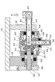
以下、本発明の一実施形態に係る切削液供給装置について図面に基づいて説明する。図1は、本発明の一実施形態に係る切削液供給装置1を示す斜視図である。また、図2は、図1に示した切削液供給装置1の側面図である。また、図3は、図2におけるIII-III断面図である。また、図4は、図3に示した断面図に対してモータ出力軸線回りに90°回動させて示す断面図である。また、図5は、図3におけるギアボックス300及び切削液供給流路400の拡大断面図である。また、図6は、図4におけるギアボックス300及び切削液供給流路400の拡大断面図である。また、図7(a)は、図2におけるVII-VII断面図である。また、図7(b)は、図2におけるVIII-VIII断面図である。また、図8は、図2におけるIX-IX断面図である。なお、図中の矢印Rは切削液の流れを示している。
Hereinafter, a cutting fluid supply apparatus according to an embodiment of the present invention will be described with reference to the drawings. FIG. 1 is a perspective view showing a cutting
本発明の一実施形態に係る切削液供給装置1は、工作機械のワークやツールに切削液やクーラント液(以下、まとめて「切削液」とする。)を供給する装置であり、厚みが十分ある細長い矩形状の金属板でできておりかつ工作機械への設置面を有するベース板(ベース部)100と、第1の支持部材110を介してベース板100に取り付けられた第1のモータ210(200)と、第2の支持部材120を介してベース板100に取り付けられ、回動中心軸線が第1のモータ210の回動中心軸線と合致するようにベース板100に第1のモータ210とベース板100の長手方向に並んで取り付けられた第2のモータ220(200)と、第3の支持部材130を介してベース板100に取り付けられたギアボックス(ハウジング)300を有している。ギアボックス300は、第3の支持部材130に対してベース板100の長手方向において回動可能に取り付けられている。なお、ギアボックス300の回動中心軸線は、第1のモータ210、第2のモータ220の回動中心軸線と一致している。ギアボックス300は、ベース板100の長手方向において第2のモータ220を挟んで第1のモータ210と反対側に位置し、切削液供給流路400(図3乃至図7(a)参照)及び切削液噴射ノズル500を有している。また、ギアボックス300の支持部材130側にはギアボックスカバー301が備わっている。なお、ギアボックスカバー301は、第2のモータ220の中空出力軸221と一体となって回動するようになっている。
A cutting
ベース板100は、その所定位置にベース板100を切削加工装置(図示せず)に取り付けるためのベース板取付孔105をそれぞれ有すると共に、ベース板100の長手方向に関してこの両側のベース板取付孔105に挟まれるようにベース板100の長手方向一方の端部に第1のモータ支持用の支持部材取付孔101が形成され、ベース板100の長手方向中央部分に第2のモータ支持用の支持部材取付孔102が形成され、長手方向他方の端部にギアボックス300を回動可能に支持する支持部材130を取り付ける支持部材取付孔103が形成されている。
The
そして、第1の支持部材110及び第2の支持部材120を介して、第1のモータ210及び第2のモータ220をベース板100に六角穴付ボルト109によってしっかりと固定すると共に、切削液供給流路400及び切削液噴射ノズル500の備わったギアボックス300を第3の支持部材130を介して六角穴付ボルト109によって第1のモータ210の出力軸回りに所定の角度範囲内で回動可能となるようにベース板100に固定されている。そして、ベース板100は、その4隅に形成された取付孔105を介してここでは図示しないボルト等の締結具により切削加工装置にしっかりと固定できるようになっている。
Then, the
第1のモータ210は、ステッピングモータからなり、図3及び図4に示すようにモータ出力軸211が隣接する第2のモータ220に向かって突出している。また、第2のモータ220は、ステッピングモータからなり、第2のモータ220の出力を伝達する中空出力軸221を有すると共に、中空出力軸221を貫通し第1のモータ210の出力を伝達する出力伝達シャフト225を備えている。なお、第1のモータ210のモータ出力軸211の先端には、キー211aが備わると共に、第2のモータ220の中空出力軸221に挿通された第1のモータ210の出力伝達シャフト225の端部には上述したキー211aに対応するキー溝225aが形成されている(図3、図4参照)。
The
これによって、切削液供給装置1の組付後に第1のモータ210の出力軸211の回動力が出力伝達シャフト225に回動トルクとして伝達できるようになっている。なお、本実施形態の場合、出力伝達シャフト225は金属でできており、中実構造のシャフトが用いられている。また、中空出力軸221は金属でできており、中空出力軸221の内径は、出力伝達シャフト225の外径よりも僅かに大きくなっている。そして、中空出力軸221と出力伝達シャフト225との間に相対回動が生じる場合に、一方の出力軸が他方の出力軸の回動を阻害しないようになっている。
As a result, the rotational force of the
ベース板100の長手方向一側に偏倚して配置されたギアボックス300は、金属でできており、第2のモータ220側がギアボックスカバー301で閉じられ、ギアボックス300内にそれぞれ金属でできた一対のベベルギアが収容されている。一対のべベルギアは、ギアボックス300内に回動可能に軸支された第1のべベルギア310と、第1のべベルギア310の回動中心軸線と直交する回動中心軸線を有しかつギアボックス300内に回動可能に軸支された第2のべベルギア320からなる。なお、第1のベルギア310と第2のべベルギア320は、本実施形態の場合、同一のモジュール及び歯数となっている。
The
更には、ギアボックス300内において所定の経路で収容配置された切削液供給流路400と、切削液供給流路400に接続されかつ先端部がギアボックス300の外部に突出し所望の方向に切削液を噴射可能とする切削液噴射ノズル500が備わっている。
Further, the cutting
切削液供給流路400は金属でできており、図5乃至図7(a)に示すように、円筒状をなす第1の流路形成部材410、金属でできており円筒状をなし、長手方向中央部が断面円形をなす膨出部425(図5及び図7(a)参照)を有する第2の流路形成部材420、及び金属でできており円筒状をなす第3の流路形成部材430を備えている。
The cutting fluid
第1の流路形成部材410は、その中心軸線が第1のべベルギア310の中心軸線と合致し、その基端部が第3の支持部材130に固定された状態でギアボックス300内に延在している。第1の流路形成部材410の基端部は、第3の支持部材130の反対側に突出した切削液供給ホース接続部450に接続されている。
The first flow
第2の流路形成部材420は、その中心軸線が第2のべベルギア320の中心軸線と合致し、ギアボックス300内に固定され、かつ第2の流路形成部材420の断面円形の膨出部425に第1の流路形成部材410の先端部が内挿されている。なお、第1の流路形成部材410の先端部と第2の流路形成部材420の基端部は密閉されている。また、第2の流路形成部材420の膨出部425は、第1の流路形成部材410に形成された4つの貫通孔411の周囲を囲むように位置し、この間の両者の隙間が切削液移動空間421を形成している。
The second flow
第3の流路形成部材430は、第2のべベルギア320と一体となってギアボックス300に対して回動可能に取り付けられ、かつ基端部が第2の流路形成部材420に連結されると共に、先端部が切削液噴射ノズル500と連結している。
The third flow
第2の流路形成部材420は、その基端部側に位置する第1のべベルギア310の中心軸線回りであって第1の流路形成部材410の周囲をギアボックス300に連動して回動可能となっている。
The second flow
第1の流路形成部材410の先端部側等と第2の流路形成部材420の基端部側との間は切削液が外部に漏れないように第1のOリング621(図5参照)によってシールされている。
The first O-ring 621 (see FIG. 5) prevents the cutting fluid from leaking to the outside between the distal end side of the first flow
第3の流路形成部材430は、切削液噴射ノズル500と共に第2のべベルギア320の回動に合わせて回動するようになっている。また、第3の流路形成部材430の基端部と第2の流路形成部材420の先端部との間は切削液が外部に漏れないように第2のOリング622(図7(a)参照)によってシールされている。また、第3の流路形成部材430の先端部側と切削液噴射ノズル500の基端部側との間はネジによる締結構造を介して切削液が外部に漏れないようになっている。
The third flow
第1の支持部材110には、第1のモータ210の出力軸211を回動可能に軸支する軸受611が備わっている。また、第2の支持部材120には、第2のモータ220の出力軸221を回動可能に軸支する軸受612が備わっている。また、ギアボックスカバー301と出力伝達シャフト225との間には軸受613が介装され、両者の相対回動を可能にしている。また、ギアボックス300と第1の流路形成部材410との間には、軸受614が介装され、両者の相対回動を可能にしている。また、ギアボックス300と第3の流路形成部材430との間には軸受615は介装され、両者の相対回動を可能にしている。
The
切削液噴射ノズル500は金属でできており、図7(a)に示すように、基端側に雌ねじを有する円柱状のノズル基端部510と、基端側に雄ねじを有し先端側にノズル基端部510の中心軸線と所定の角度(本実施形態では90度)をなしてノズル基端部510の中心軸線に対して所定の方向に切削液を噴射するノズル先端部520からなる。そして、ノズル基端部510の中心軸線が第2のべベルギア320の中心軸線と合致し、第2のべベルギア320の回動に応じて切削液噴射ノズル500のノズル先端部520から中心軸線回りに所望の方向に切削液が噴射されるようになっている。
The cutting
具体的には、第2のモータ220のみが回動した際には、第1のべベルギア310及び第2のべベルギア320が互いに相対回動しない状態で第2のモータ220の中空出力軸221及びギアボックス300と一体となった切削液噴射ノズル500自体が第1のべベルギア310の中心軸線回りにギアボックス300全体と共に回動するようになっている。
Specifically, when only the
一方、第1のモータ210のみが回動した場合、第1のモータ210の出力軸に連結された出力伝達シャフト225が一体に回動し、これに応じて第1のべベルギア310が回動すると共に、第1のべベルギア310の回動に応じてこれに噛合した第2のべベルギア320が回動するようになっている。これよって、切削液噴射ノズル500の中心軸線が第2のべベルギア320の中心軸線回りに回動し、切削液噴射ノズル500のノズル先端部520の向きが第2のべベルギア320の中心軸線回りに所定の角度範囲内で回動するようになっている。なお、第1のモータ210と第2のモータ220が同時に回動した場合、切削液噴射ノズル500は上述した2つの回動動作を複合して行うようになっている。
On the other hand, when only the
続いて、本発明の一実施形態に係る切削液供給装置1の組付手順について説明する。図9は、図1に示した切削液供給装置1の図2に対応する分解側面図である。
Then, the assembly | attachment procedure of the cutting
本発明の一実施形態に係る切削液供給装置1を組み付けるにあたって、最初にベース板100と、第1のモータ210、第2のモータ220、及びギアボックス300を用意する。なお、本実施形態の場合、第1のモータ210に第1の支持部材110を予め取り付けると共に、第2のモータ220に第2の支持部材120及びギアボックスカバー301並びに第1のベベルギア310を予め取り付けておく。また、ギアボックス300には予め第2のベベルギア320を取り付けておくと共に、第3の支持部材130、第1乃至第3の流路形成部材410,420,430、切削液噴射ノズル500、切削液供給ホース接続部450を取り付けておく。
In assembling the cutting
次いで、第2のモータ220の中空出力軸221に第1のモータ210の出力伝達シャフト225を挿通する(図9参照)。そして、第1のモータ210の出力軸211に第1のモータ210の出力伝達シャフト225の一端を連結すると共に、第1のモータ210の出力伝達シャフト225の他端を第1のベベルギア310に連結する。これと同時に第2のモータ220の中空出力軸221の端部を、ギアボックスカバー301を介してギアボックス300に連結する。そして、第1のモータ210、第2のモータ220、及びギアボックス300を第1乃至第3の支持部材110,120,130を介して六角穴付ボルト109によってベース板100に取り付け、切削液供給装置1の組付作業を完了する。
Next, the
このようにして組み付けられた切削供給装置1では、第1のモータ210の出力軸211に連結された出力伝達シャフト225の回動に応じて第1のべベルギア310が回動すると共に、第1のべベルギア310の回動に応じてこれに噛合した第2のべベルギア320が回動する。その結果、切削液噴射ノズル500の中心軸線が第2のべベルギア320の中心軸線回りに回動し、切削液噴射ノズル500のノズル先端部520の向きが第2のべベルギア320の中心軸線回りに所定の角度範囲内で回動する。また、第2のモータ220のみが回動した際には、第1のべベルギア310及び第2のべベルギア320が互いに相対回動しない状態で第1のモータ210の出力軸、即ち第1のべベルギア310の中心軸線回りに切削液噴射ノズル500自体がギアボックス300全体と共に回動する。なお、第1のモータ210と第2のモータ220が同時に回動した場合、切削液噴射ノズル500は上述した2つの回動動作を複合した回動を行うようになっている。
In the cutting and feeding
以下、上述した実施形態に係る切削液供給装置1における切削液(図中矢印R参照)の流れについて説明を行う。図中矢印Rで示す切削液は、切削液供給ホースに接続された切削液供給ホース接続部450を介して第1の流路形成部材410に流入する。そして、第1の流路形成部材410の先端側に形成された複数の貫通孔411を介してギアボックス300に固定された第2の流路形成部材420の切削液移動空間421に流入する。この際、第1のOリング621(図5参照)によって切削液は外部に漏れることなく第1の流路形成部材410から第2の流路形成部材420に流れる。なお、本実施形態においては、貫通孔の個数は4つとなっているが、このような個数に限定されないことは言うまでもない。
Hereinafter, the flow of the cutting fluid (see arrow R in the figure) in the cutting
そして、切削液は、第2の流路形成部材420からギアボックス300に対して相対回動可能な第3の流路形成部材430に流入する。この際、第2のOリング(図7(a)参照)によって切削液供給液は外部に漏れることなく第2の流路形成部材420から第3の流路形成部材430に流れる。そして、切削液は、第3の流路形成部材430から切削液噴射ノズル500の基端部510を介して切削液噴射ノズル500の先端部520から加工部に噴射される。この際、第3の流路形成部材430の先端側と切削液噴射ノズル500の基端側とは、互いに螺合しているので、この部分から切削液が漏れることはない。
Then, the cutting fluid flows from the second flow
このような切削液の流れと同時に切削液噴射ノズル500は以下のように動作する。切削液供給装置1を作動させると、第1のモータ210の出力軸211の回動を第2のモータ220の中空出力軸221に挿通されている出力伝達シャフト225に伝え、これを回動させ、出力伝達シャフト225に固定されている第1のベベルギア310を回動させ、第1のベベルギア310が噛合している第2のベベルギア320を回動させ、第2のベベルギア320に固定されている第3の流路形成部材430が回動し、第3の流路形成部材430が切削液噴射ノズル500を回動させてノズル先端部520が図1中左右作動を行う。
Simultaneously with the flow of the cutting fluid, the cutting
一方、第2のモータ220を回動させると、この中空出力軸221に固定されているギアボックスカバーが回動し、これと一体化されているギアボックス300が回動して切削液噴射ノズル500の図1中上下動作を行い、ノズル先端部520もこれに合わせて上下に向きを変える。
On the other hand, when the
なお、第1のモータ210の回動動作と第2のモータ220の回動動作を複合して作動させると、上述したように切削液を所望の方向に向かって噴射することが可能となる。
Note that when the rotational operation of the
上述した本実施形態に係る切削液供給装置1によると、切削液供給装置1の切削液供給流路400と切削液供給タンクを繋ぐ切削液供給ホースの可動範囲(切削液供給ホースの動くエリア)を最小限に抑えることできる。これによって、切削液供給装置1と切削液供給タンクとの配置スペースをなるべく小さくすることができ、切削加工装置全体の小型化を図ることができる。
According to the cutting
また、切削液噴射ノズル500の両側に第1のモータ210と第2のモータ220を配置しなくて済むため、切削液を供給する対象物である加工装置の狭い部位にも切削液を供給できる。
Moreover, since it is not necessary to arrange the
また、切削液供給装置1の作動中に切削液供給装置1の切削液供給ホース接続部450の方向が一定の方向を向いているので、長さの長い切削液供給ホースを切削液供給装置1と切削液供給タンクの間に備える必要がなくなり、このような長さの長い切削液供給ホースの動きが広いスペースで生じることによる作業環境の悪化を回避することができる。
Further, since the direction of the cutting fluid supply
なお、本発明で使用されるモータは、上述の実施形態のようにステッピングモータに限定されるものではなく、(ブラシ、ブラシレス)DCモータ等、様々なモータを用いることができる。 In addition, the motor used by this invention is not limited to a stepping motor like the above-mentioned embodiment, Various motors, such as a (brush, brushless) DC motor, can be used.
また、第1の支持部材110及び第2の支持部材120は本発明においては必ずしも必要とされず、モータ自体に取付け基台を備え、スペーサ等で各モータの出力軸の中心軸線とハウジングの回動中心軸線を合致するように調整しても良い。
In addition, the
また、上述の実施形態で紹介した各構成要素の形状や寸法、数値、材質はあくまで例示的なもので、本発明の範囲を逸脱しない限り、様々な形状や寸法、数値、材質を適宜選択できることは言うまでもない。具体的には、上述の実施形態においては、ベース板や支持部材、ギアボックス、べベルギアの材質は金属としたが、本発明の作用を発揮し得る範囲内であれば材質は必ずしも金属に限定されず、強度と成型性に優れた樹脂等その他の材質であっても構わない。また、ベース板に形成された取付孔や第1の流路形成部材に形成された流路孔の個数についても、本実施形態の個数に限定されるものではない。 In addition, the shape, dimensions, numerical values, and materials of each component introduced in the above-described embodiment are merely exemplary, and various shapes, dimensions, numerical values, and materials can be selected as appropriate without departing from the scope of the present invention. Needless to say. Specifically, in the above-described embodiment, the base plate, the support member, the gear box, and the bevel gear are made of metal. However, the material is not necessarily limited to metal as long as the function of the present invention can be achieved. Alternatively, other materials such as a resin excellent in strength and moldability may be used. Further, the number of mounting holes formed in the base plate and the number of flow path holes formed in the first flow path forming member is not limited to the number of the present embodiment.
また、本実施形態においては、切削液噴射ノズルのノズル先端から工作機械のワークやツールに切削液を噴射したが、必ずしもこのような切削液に限定されることはなく、研削油や切削液、切削油、研磨液、冷却液(クーラント液)、冷却油(クーラント油)をクーラントノズルのノズル先端から工作機械のワークやツールに供給しても良い。即ち、本実施形態においてはノズル先端から切削液をツールやワークに対して噴射したが、これとは異なり研削液をツールやワークに供給するようにしても良い。 Further, in the present embodiment, the cutting fluid is sprayed from the tip of the cutting fluid spray nozzle to the workpiece or tool of the machine tool, but is not necessarily limited to such a cutting fluid. Cutting oil, polishing liquid, cooling liquid (coolant liquid), or cooling oil (coolant oil) may be supplied to the workpiece or tool of the machine tool from the nozzle tip of the coolant nozzle. That is, in this embodiment, the cutting fluid is sprayed from the nozzle tip to the tool or workpiece. However, the grinding fluid may be supplied to the tool or workpiece differently.
1 切削液供給装置
100 ベース板(ベース部)
110 第1の支持部材
120 第2の支持部材
130 第3の支持部材
210(200) 第1のモータ
211 モータ出力軸
220(200) 第2のモータ
221 中空出力軸
225 出力伝達シャフト
300 ギアボックス(ハウジング)
301 ギアボックスカバー
310 第1のべベルギア
320 第2のべベルギア
400 切削液供給流路
410 第1の流路形成部材
411 貫通孔
420 第2の流路形成部材
421 切削液移動空間
430 第3の流路形成部材
450 切削液供給ホース接続部
500 切削液噴射ノズル
510 ノズル基端部
520 ノズル先端部
611,612,613,614,615 軸受
1 Cutting
DESCRIPTION OF
301
Claims (2)
工作機械への設置面を有するベース部と
前記ベース部に取り付けられた第1のモータと、
回動中心軸線が前記第1のモータの回動中心軸線と合致するように前記第1のモータと並んで前記ベース部に取り付けられた第2のモータと、
前記ベース部に取り付けられ内部にベベルギアを有するハウジングと、
前記ハウジング内に設けられたべベルギアに取り付けられ、前記ハウジングに接続される切削液供給ホースから流入する切削液を所望の方向に噴射可能とする流路形成部材及び切削液噴射ノズルを備え、
前記第2のモータは、該第2のモータの出力を伝達する中空出力軸を有すると共に、前記中空出力軸を貫通し前記第1のモータの出力を伝達する出力伝達シャフトを備えており、
前記べベルギアは、前記ハウジング内に回動可能に軸支されその軸線が第1のモータの出力軸と合致した第1のべベルギアと、該第1のべベルギアの出力軸と直交する出力軸を有しかつ前記第1のベベルギアと噛み合った状態で前記ハウジング内に回動可能に軸支された第2のべベルギアからなり、
前記流路形成部材の一部は、その中心軸線が前記第1のべベルギアの中心軸線に対応するように形成されると共に、該流路形成部材の残りの一部は、その中心軸線が前記第2のベベルギアの中心軸線に対応するように形成され、
前記第1のモータの出力軸に連結された前記出力伝達シャフトの回動に応じて前記第1のべベルギアが回動すると共に、該第1のべベルギアの回動に応じてこれに噛合した第2のべベルギアが回動した場合に、前記切削液噴射ノズルが前記第2のべベルギアの中心軸線回りに回動して該中心軸線回りの所定方向に前記切削液が噴射されると共に、前記第2のモータの中空出力軸が回動することで、前記切削液噴射ノズル全体が前記第1のべベルギアの中心軸線回りに回動して該中心軸線回りの所定方向に前記切削液が噴射されることを特徴とする切削液供給装置。 In a cutting fluid supply device that supplies cutting fluid and coolant fluid to workpieces and tools of machine tools,
A base portion having an installation surface for a machine tool; a first motor attached to the base portion;
A second motor attached to the base portion alongside the first motor such that a rotation center axis line coincides with a rotation center axis line of the first motor;
A housing attached to the base portion and having a bevel gear inside;
A flow path forming member that is attached to a bevel gear provided in the housing and that enables cutting fluid flowing from a cutting fluid supply hose connected to the housing to be sprayed in a desired direction, and a cutting fluid spray nozzle are provided.
The second motor includes a hollow output shaft that transmits the output of the second motor, and includes an output transmission shaft that passes through the hollow output shaft and transmits the output of the first motor.
The bevel gear is pivotally supported in the housing and has a first bevel gear whose axis coincides with the output shaft of the first motor, and an output shaft orthogonal to the output shaft of the first bevel gear. And a second bevel gear pivotally supported in the housing in a state of meshing with the first bevel gear,
A part of the flow path forming member is formed so that a central axis thereof corresponds to a central axis of the first bevel gear, and a remaining part of the flow path forming member has a central axis of the first bevel gear. Formed to correspond to the central axis of the second bevel gear,
The first bevel gear rotates according to the rotation of the output transmission shaft connected to the output shaft of the first motor, and meshes with the first bevel gear according to the rotation of the first bevel gear. When the second bevel gear rotates, the cutting fluid injection nozzle rotates about the central axis of the second bevel gear and the cutting fluid is injected in a predetermined direction around the central axis, When the hollow output shaft of the second motor is rotated, the entire cutting fluid injection nozzle is rotated around the central axis of the first bevel gear, and the cutting fluid is supplied in a predetermined direction around the central axis. A cutting fluid supply device which is jetted.
前記第1のモータは、第1の支持部材を介して前記ベース板に固定され、
前記第2のモータは、第2の支持部材を介して前記ベース板に固定され、
前記ハウジングは、前記第1及び第2のべベルギアを収容するギアボックスからなり、第3の支持部材を介して前記ベース板に回動可能に軸支され、
前記流路形成部材は、第1の流路形成部材、第2の流路形成部材、及び第3の流路形成部材を備え、
前記第1の流路形成部材は、その中心軸線が前記第1のベベルギアの中心軸線と一致するように前記ギアボックス内に延在して該ギアボックス内に備わり、かつ前記第1の流路形成部材の先端部は、前記切削液を前記第2の流路形成部材に流入させる切削液流入用貫通孔が形成され、
前記第2の流路形成部材は、その中心軸線が前記第2のベベルギアの中心軸線と一致するように前記ギアボックス内に備わり、かつ前記第2の流路形成部材の基端部側に前記第1の流路形成部材の先端部が内挿され、前記第2の流路形成部材は、その基端部側にある前記第1のベベルギアの中心軸線回りに前記第1の流路形成部材の周囲を前記ギアボックスと一体に回動可能となっており、
前記第3の流路形成部材は、前記切削液噴射ノズルと共に前記第2のべベルギアと一体に回動するように取り付けられ、かつその基端部が前記第2の流路形成部材の先端部に連結されると共に、その先端部が前記切削液噴射ノズルと連結されており、
前記第2の流路形成部材の基端部側と前記第1の流路形成部材の先端部側との間は前記切削液が外部に漏れないようにシールされ、
前記第3の流路形成部材の基端部側と前記第2の流路形成部材の先端部側との間は前記切削液が外部に漏れないようにシールされ、
前記第3の流路形成部材の先端部側と前記切削液噴射ノズルの基端部側との間は前記切削液が外部に漏れないようになったことを特徴とする請求項1に記載の切削液供給装置。 The base part is composed of an elongated plate-like base plate,
The first motor is fixed to the base plate via a first support member,
The second motor is fixed to the base plate via a second support member,
The housing includes a gear box that houses the first and second bevel gears, and is pivotally supported by the base plate via a third support member.
The flow path forming member includes a first flow path forming member, a second flow path forming member, and a third flow path forming member,
The first flow path forming member extends in the gear box so that a central axis thereof coincides with a central axis of the first bevel gear, and is provided in the gear box. A cutting fluid inflow through hole for allowing the cutting fluid to flow into the second flow path forming member is formed at the tip of the forming member,
The second flow path forming member is provided in the gear box so that a central axis thereof coincides with a central axis of the second bevel gear, and the second flow path forming member is disposed on the proximal end side of the second flow path forming member. A distal end portion of the first flow path forming member is inserted, and the second flow path forming member is arranged around the central axis of the first bevel gear on the base end side. Can be rotated integrally with the gear box,
The third flow path forming member is attached so as to rotate together with the second bevel gear together with the cutting fluid injection nozzle, and a base end portion thereof is a distal end portion of the second flow path forming member. And its tip is connected to the cutting fluid injection nozzle,
Between the base end side of the second flow path forming member and the front end side of the first flow path forming member is sealed so that the cutting fluid does not leak outside,
Between the base end side of the third flow path forming member and the front end side of the second flow path forming member is sealed so that the cutting fluid does not leak to the outside,
The cutting fluid does not leak to the outside between a distal end portion side of the third flow path forming member and a proximal end portion side of the cutting fluid injection nozzle . Cutting fluid supply device.
Priority Applications (1)
| Application Number | Priority Date | Filing Date | Title |
|---|---|---|---|
| JP2012019319A JP5856496B2 (en) | 2012-01-31 | 2012-01-31 | Cutting fluid supply device |
Applications Claiming Priority (1)
| Application Number | Priority Date | Filing Date | Title |
|---|---|---|---|
| JP2012019319A JP5856496B2 (en) | 2012-01-31 | 2012-01-31 | Cutting fluid supply device |
Publications (2)
| Publication Number | Publication Date |
|---|---|
| JP2013154460A JP2013154460A (en) | 2013-08-15 |
| JP5856496B2 true JP5856496B2 (en) | 2016-02-09 |
Family
ID=49050159
Family Applications (1)
| Application Number | Title | Priority Date | Filing Date |
|---|---|---|---|
| JP2012019319A Active JP5856496B2 (en) | 2012-01-31 | 2012-01-31 | Cutting fluid supply device |
Country Status (1)
| Country | Link |
|---|---|
| JP (1) | JP5856496B2 (en) |
Family Cites Families (6)
| Publication number | Priority date | Publication date | Assignee | Title |
|---|---|---|---|---|
| JPH0318117Y2 (en) * | 1985-07-05 | 1991-04-17 | ||
| US4702124A (en) * | 1986-05-30 | 1987-10-27 | Accuratio Systems, Inc. | Power transmission device |
| JP2672994B2 (en) * | 1988-12-29 | 1997-11-05 | 株式会社日平トヤマ | Laser processing head |
| JP2680101B2 (en) * | 1989-01-31 | 1997-11-19 | 株式会社日平トヤマ | Laser processing head |
| EP0794036B1 (en) * | 1996-03-07 | 2000-05-10 | Messer Griesheim Gmbh | Machine for polishing and/or grinding |
| JP4167583B2 (en) * | 2003-10-31 | 2008-10-15 | 株式会社スギノマシン | Rotating nozzle unit of automatic rotary cleaning device |
-
2012
- 2012-01-31 JP JP2012019319A patent/JP5856496B2/en active Active
Also Published As
| Publication number | Publication date |
|---|---|
| JP2013154460A (en) | 2013-08-15 |
Similar Documents
| Publication | Publication Date | Title |
|---|---|---|
| JP5283012B2 (en) | NOZZLE WITH EXCHANGE FUNCTION, NOZZLE DEVICE WITH EXCHANGE FUNCTION, AND COATING APPARATUS PROVIDED WITH IT | |
| JP5986345B1 (en) | Coolant injection device | |
| JP6062838B2 (en) | Coolant injection device | |
| CN103008430B (en) | High-pressure water jet tilting and rotating device | |
| JP2017104766A (en) | Cleaning tool attachment | |
| WO2019106930A1 (en) | On-board sensor cleaning device | |
| JP5856496B2 (en) | Cutting fluid supply device | |
| KR101308041B1 (en) | 3-axes milling head for a machine tool | |
| JP5816056B2 (en) | Structure for supplying grinding fluid to bi-directionally operating coolant nozzle and coolant nozzle having this structure | |
| KR102188835B1 (en) | 4-axis drilling machine | |
| JP5756743B2 (en) | Cutting fluid injection device | |
| JP5802485B2 (en) | Coolant nozzle bi-directional operation structure | |
| JP2014144502A (en) | Cutting fluid supply device | |
| JP2014140938A (en) | Cutting liquid supply device | |
| JP2005066804A (en) | Power tool | |
| CN202491134U (en) | Cooling liquid jet device | |
| JP4202118B2 (en) | Nozzle for cleaning | |
| JP5221186B2 (en) | Cutting machine | |
| JP2015066633A (en) | Cutting liquid supply device | |
| JP2014213417A (en) | Portable cutter | |
| JP2008068377A (en) | Coolant pressurizing device | |
| CN220071141U (en) | Rotary haze spray head for environmental treatment | |
| KR200421597Y1 (en) | Tool substitution of the machine tool spur gear assembly | |
| JP2010214488A (en) | Mechanism and device for moving nozzle | |
| TWM407806U (en) | Programmable coolant protractor |
Legal Events
| Date | Code | Title | Description |
|---|---|---|---|
| A621 | Written request for application examination |
Free format text: JAPANESE INTERMEDIATE CODE: A621 Effective date: 20150108 |
|
| A977 | Report on retrieval |
Free format text: JAPANESE INTERMEDIATE CODE: A971007 Effective date: 20151022 |
|
| A131 | Notification of reasons for refusal |
Free format text: JAPANESE INTERMEDIATE CODE: A131 Effective date: 20151023 |
|
| A521 | Written amendment |
Free format text: JAPANESE INTERMEDIATE CODE: A523 Effective date: 20151117 |
|
| TRDD | Decision of grant or rejection written | ||
| A01 | Written decision to grant a patent or to grant a registration (utility model) |
Free format text: JAPANESE INTERMEDIATE CODE: A01 Effective date: 20151207 |
|
| A61 | First payment of annual fees (during grant procedure) |
Free format text: JAPANESE INTERMEDIATE CODE: A61 Effective date: 20151211 |
|
| R150 | Certificate of patent or registration of utility model |
Ref document number: 5856496 Country of ref document: JP Free format text: JAPANESE INTERMEDIATE CODE: R150 |
|
| R250 | Receipt of annual fees |
Free format text: JAPANESE INTERMEDIATE CODE: R250 |
|
| R250 | Receipt of annual fees |
Free format text: JAPANESE INTERMEDIATE CODE: R250 |
|
| S533 | Written request for registration of change of name |
Free format text: JAPANESE INTERMEDIATE CODE: R313533 |
|
| R350 | Written notification of registration of transfer |
Free format text: JAPANESE INTERMEDIATE CODE: R350 |