JP5855893B2 - Method for producing non-aqueous lithium storage element - Google Patents
Method for producing non-aqueous lithium storage element Download PDFInfo
- Publication number
- JP5855893B2 JP5855893B2 JP2011225742A JP2011225742A JP5855893B2 JP 5855893 B2 JP5855893 B2 JP 5855893B2 JP 2011225742 A JP2011225742 A JP 2011225742A JP 2011225742 A JP2011225742 A JP 2011225742A JP 5855893 B2 JP5855893 B2 JP 5855893B2
- Authority
- JP
- Japan
- Prior art keywords
- double
- negative electrode
- sided
- electrode
- active material
- Prior art date
- Legal status (The legal status is an assumption and is not a legal conclusion. Google has not performed a legal analysis and makes no representation as to the accuracy of the status listed.)
- Expired - Fee Related
Links
Images


Classifications
-
- Y—GENERAL TAGGING OF NEW TECHNOLOGICAL DEVELOPMENTS; GENERAL TAGGING OF CROSS-SECTIONAL TECHNOLOGIES SPANNING OVER SEVERAL SECTIONS OF THE IPC; TECHNICAL SUBJECTS COVERED BY FORMER USPC CROSS-REFERENCE ART COLLECTIONS [XRACs] AND DIGESTS
- Y02—TECHNOLOGIES OR APPLICATIONS FOR MITIGATION OR ADAPTATION AGAINST CLIMATE CHANGE
- Y02E—REDUCTION OF GREENHOUSE GAS [GHG] EMISSIONS, RELATED TO ENERGY GENERATION, TRANSMISSION OR DISTRIBUTION
- Y02E60/00—Enabling technologies; Technologies with a potential or indirect contribution to GHG emissions mitigation
- Y02E60/10—Energy storage using batteries
-
- Y—GENERAL TAGGING OF NEW TECHNOLOGICAL DEVELOPMENTS; GENERAL TAGGING OF CROSS-SECTIONAL TECHNOLOGIES SPANNING OVER SEVERAL SECTIONS OF THE IPC; TECHNICAL SUBJECTS COVERED BY FORMER USPC CROSS-REFERENCE ART COLLECTIONS [XRACs] AND DIGESTS
- Y02—TECHNOLOGIES OR APPLICATIONS FOR MITIGATION OR ADAPTATION AGAINST CLIMATE CHANGE
- Y02P—CLIMATE CHANGE MITIGATION TECHNOLOGIES IN THE PRODUCTION OR PROCESSING OF GOODS
- Y02P70/00—Climate change mitigation technologies in the production process for final industrial or consumer products
- Y02P70/50—Manufacturing or production processes characterised by the final manufactured product
Description
本発明は、非水系リチウム型蓄電素子の製造方法に関する。 The present invention relates to the production how a non-aqueous lithium-type storage element.
近年、地球環境の保全および省資源を目指したエネルギーの有効利用を目的として、自動車において、内燃機関または燃料電池、モータ、及び蓄電素子を組み合わせたハイブリット駆動システム(以下、単に「駆動システム」という。)が注目を集めている。
上記駆動システム向けの蓄電素子が果たす役割の一つとして、内燃機関または燃料電池を、最大効率を発揮できる一定の出力で運転させたまま、該駆動システムの負荷の増減を吸収することがあげられる。
In recent years, hybrid drive systems (hereinafter simply referred to as “drive systems”) that combine an internal combustion engine or a fuel cell, a motor, and a power storage element in an automobile for the purpose of protecting the global environment and effectively using energy for resource saving. ) Is attracting attention.
One of the roles played by the power storage element for the drive system is to absorb the increase and decrease of the load of the drive system while the internal combustion engine or the fuel cell is operated at a constant output capable of maximizing the efficiency. .
すなわち、加速時には内燃機関または燃料電池からの出力だけでは不足するパワーを、蓄電素子からモータに電力供給することで補い、減速時にはモータを発電機として用いて余剰に発生した電力を当該蓄電素子に回収する、という役割である。
上記駆動システムに使用される蓄電素子に求められる第一の要求は、入出力特性が優れていることである。これは、短時間の間に蓄電素子がどれだけの量のエネルギーを吸収または放出できるかが重要であるためである。
In other words, power that is insufficient with only the output from the internal combustion engine or the fuel cell during acceleration is compensated by supplying power from the power storage element to the motor, and excess power generated by using the motor as a generator during deceleration is supplied to the power storage element. The role is to collect.
The first requirement for an electric storage element used in the drive system is that input / output characteristics are excellent. This is because it is important how much energy the power storage element can absorb or release in a short time.
また、これらの蓄電素子に求められる第二の要求は、エネルギー密度が高いことである。エネルギー密度が低いと、自動車の加速に必要な電力を供給したり、減速で発生したエネルギーを余すことなく回生したりするために必要な蓄電素子の重量や体積が大きくなってしまい、自動車という限られた空間に効率よく収納することが困難になるためである。 現在、このような駆動システムに向けた蓄電素子としては、ニッケル水素電池が主流であり、電気二重層キャパシタ、リチウムイオン電池が採用されつつある。 In addition, a second requirement for these power storage elements is high energy density. If the energy density is low, the weight and volume of the electricity storage element required to supply the electric power necessary for accelerating the car and to regenerate the energy generated by the deceleration will not increase. This is because it becomes difficult to efficiently store in the space provided. Currently, nickel-metal hydride batteries are the mainstream as storage elements for such drive systems, and electric double layer capacitors and lithium ion batteries are being adopted.
また、自動車向けの用途以外でも、電子機器の瞬間的なバックアップ用途として、数秒程度で放電可能な高出力を要求される用途もあり、これらの蓄電素子の入出力特性の改善は急務である。
上述の電気二重層キャパシタとしては、電解液が水系のもの(以下、「水系キャパシタ」という。)と非水系のもの(以下、「非水系キャパシタ」という。)が知られている。
In addition to applications for automobiles, there are applications that require a high output that can be discharged in a few seconds as an instantaneous backup application for electronic devices, and improvement of the input / output characteristics of these power storage elements is urgent.
As the above-mentioned electric double layer capacitor, there are known an electrolytic solution that is aqueous (hereinafter referred to as “aqueous capacitor”) and a non-aqueous electrolyte (hereinafter referred to as “non-aqueous capacitor”).
しかしながら、水系キャパシタは入出力特性に優れるものの、電解液である水が電気分解するために、蓄電素子あたりの耐電圧が低く、エネルギー密度を高くできないという問題点がある。また、非水系キャパシタは電解液の電気分解に対する耐電圧が高いために水系キャパシタと比較してエネルギー密度を高くすることはできるものの、入出力特性が水系キャパシタよりも劣るという問題点がある。また、非水系キャパシタは水系キャパシタよりはエネルギー密度が高いものの、二次電池と比べるとエネルギー密度が十分ではない。 However, although the water-based capacitor is excellent in input / output characteristics, there is a problem that the withstand voltage per power storage element is low and the energy density cannot be increased because water as an electrolytic solution is electrolyzed. In addition, since the non-aqueous capacitor has a high withstand voltage against electrolysis of the electrolytic solution, the energy density can be increased as compared with the aqueous capacitor, but the input / output characteristics are inferior to those of the aqueous capacitor. In addition, although the non-aqueous capacitor has a higher energy density than the water-based capacitor, the energy density is not sufficient compared to the secondary battery.
一方、ニッケル水素電池やリチウムイオン二次電池は、エネルギー密度は高いものの、電気二重層キャパシタと比べると入出力特性や信頼性が十分ではない。このため、高入出力特性、高エネルギー密度、高信頼性のすべてを兼ね備えた蓄電素子の実用化が強く求められている。
ところで、このような蓄電素子として、リチウムイオンキャパシタが提案されている。
On the other hand, although nickel-metal hydride batteries and lithium ion secondary batteries have high energy density, input / output characteristics and reliability are not sufficient compared to electric double layer capacitors. For this reason, there is a strong demand for the practical use of a power storage device having all of high input / output characteristics, high energy density, and high reliability.
Incidentally, a lithium ion capacitor has been proposed as such a storage element.
リチウムイオンキャパシタは、リチウム塩を含む非水系電解液を使用する蓄電素子(非水系リチウム型蓄電素子)の一種であり、正極においては電気二重層キャパシタと同様の陰イオンの吸着・脱着による非ファラデー反応、負極においてはリチウムイオン二次電池と同様のリチウムイオンの吸蔵・放出によるファラデー反応によって充放電を行う蓄電素子である。 Lithium-ion capacitors are a type of energy storage device that uses a non-aqueous electrolyte containing a lithium salt (non-aqueous lithium-type energy storage device). The positive electrode is a non-Faraday based on anion adsorption / desorption similar to an electric double layer capacitor. In the reaction and negative electrode, it is a power storage element that charges and discharges by a Faraday reaction by insertion and extraction of lithium ions similar to a lithium ion secondary battery.
リチウムイオンキャパシタは、二次電池と比べると入出力特性や信頼性に優れ、電気二重層キャパシタと比べるとエネルギー密度に優れる。
リチウムイオンキャパシタの具体的な正極および負極の材料としては、正極に活性炭、負極に黒鉛などの炭素質材料を用いた蓄電素子が提案されている(例えば、特許文献1参照)。
Lithium ion capacitors are superior in input / output characteristics and reliability as compared to secondary batteries, and in energy density as compared to electric double layer capacitors.
As a specific positive electrode and negative electrode material of a lithium ion capacitor, a storage element using activated carbon for the positive electrode and a carbonaceous material such as graphite for the negative electrode has been proposed (see, for example, Patent Document 1).
また、正極に活性炭、負極に、活性炭表面に炭素質材料を被覆した複合多孔性材料を使用する蓄電素子も提案されている(例えば、特許文献2参照)。
ところで、非水系リチウム型蓄電素子において、一般に負極活物質として使用される炭素質材料は、最初にリチウムイオンを吸蔵(充電)したときに、該炭素質材料の表面に非水電解液由来の反応物とリチウムイオンとを含む固体電解質膜が形成されること、及び通常の放電条件では放電できないようなリチウムイオンが該炭素質材料の内部に溜まったりすることに起因して、最初に吸蔵した該リチウムイオンのすべてを放出することはできず、該蓄電素子内の通常の充放電に関与できるリチウムイオンの損失を招くことが知られている。特に、比表面積が大きい炭素質材料の場合はこのリチウムイオンの損失が顕著である。
In addition, a power storage element using a composite porous material in which activated carbon is used for the positive electrode and a carbonaceous material is coated on the surface of the activated carbon on the negative electrode has also been proposed (see, for example, Patent Document 2).
By the way, in a non-aqueous lithium-type energy storage device, a carbonaceous material generally used as a negative electrode active material is a reaction derived from a nonaqueous electrolyte solution on the surface of the carbonaceous material when lithium ions are first occluded (charged). The first occlusion is caused by the formation of a solid electrolyte membrane containing a product and lithium ions, and the accumulation of lithium ions that cannot be discharged under normal discharge conditions. It is known that not all of the lithium ions can be released, resulting in a loss of lithium ions that can participate in normal charge / discharge in the electricity storage device. In particular, in the case of a carbonaceous material having a large specific surface area, the loss of lithium ions is remarkable.
このようなリチウムイオンの損失は、リチウムイオン二次電池のように蓄電素子内に活物質としてリチウムイオンの供給源(即ちLiCoO2 のようなリチウム含有遷移金属酸化物)を有する場合には、正極から出たリチウムイオンの不可逆的な損失となり該蓄電素子の容量低下が起こる。また、蓄電素子内にリチウムイオンを含有するのが、電解液だけであるリチウムイオンキャパシタの場合には、電解液中のリチウムイオンが損失する結果、電解質濃度の低下を招き、内部抵抗の上昇による入出力特性の低下ならびに容量の低下が起こる。 Such a loss of lithium ions is caused by the positive electrode when a lithium ion supply source (that is, a lithium-containing transition metal oxide such as LiCoO 2 ) is provided as an active material in the storage element as in a lithium ion secondary battery. The irreversible loss of lithium ions emitted from the battery causes a reduction in the capacity of the power storage element. In addition, in the case of a lithium ion capacitor in which the lithium ion is contained only in the electrolytic solution in the electric storage element, the lithium ion in the electrolytic solution is lost, resulting in a decrease in the electrolyte concentration and an increase in internal resistance. The input / output characteristics and capacity are reduced.
上述のリチウムイオンの損失を補償するためのひとつの手段として、リチウムイオンを蓄電素子内部にあらかじめ添加して(以下「プリドープ」ともいう。)、損失により減少するリチウムイオンを補給することが考えられる。
このプリドープは、特に電解液以外にリチウムイオン供給源のないリチウムイオンキャパシタにおいては、必須であるといえる。
As one means for compensating for the above-described loss of lithium ions, it is conceivable to add lithium ions in the storage element in advance (hereinafter also referred to as “pre-dope”) and supply lithium ions that decrease due to the loss. .
This pre-doping can be said to be essential particularly in a lithium ion capacitor having no lithium ion supply source other than the electrolytic solution.
リチウムイオンの蓄電素子内部へのプリドープ方法は、負極活物質層上や、正極シートに対向していない負極集電体上(例えば、特許文献3参照)など、いろいろと提案されている。
しかしながら、最も負極活物質層へのリチウムイオンのプリドープが早く、確実に実施できる方法は、負極活物質層の表面に金属リチウム箔を貼り付け、非水電解液を注入することである。このような例として、厚み10μm以上70μm以下の金属リチウム箔を用いることが提案されている(例えば、特許文献4参照)。
Various methods for pre-doping lithium ion into the storage element have been proposed, such as on a negative electrode active material layer or on a negative electrode current collector not facing the positive electrode sheet (see, for example, Patent Document 3).
However, the fastest and most reliable method of pre-doping lithium ions into the negative electrode active material layer is to attach a metal lithium foil to the surface of the negative electrode active material layer and inject a non-aqueous electrolyte. As such an example, it has been proposed to use a metal lithium foil having a thickness of 10 μm to 70 μm (see, for example, Patent Document 4).
しかしながら、工業的に生産されている金属リチウム箔は通常30μm以上の厚みがあり、非常に特殊な用途向けとして少量の入手が可能な金属リチウム箔であっても厚みが20μmであり、それ以下の厚みの金属リチウム箔は自製しない限り入手が不可能である。
一方、厚みが20μmの金属リチウム箔は、面積1cm2あたり約4.12mAhの電気量(リチウムの分子量6.94、密度0.534g/cm3から計算された電気量。)に相当するリチウム量であり、携帯電話などに使用される民生用リチウムイオン電池の電極の単位面積あたりの容量である約3mAh/cm2の約1.4倍の量である。
However, industrially produced metal lithium foils usually have a thickness of 30 μm or more, and even a metal lithium foil that can be obtained in a small amount for very special applications has a thickness of 20 μm, which is less than that. Thick metal lithium foil is not available unless it is made by itself.
On the other hand, a lithium metal foil having a thickness of 20 μm has an amount of lithium corresponding to an amount of electricity of about 4.12 mAh per 1 cm 2 of area (an amount of electricity calculated from a lithium molecular weight of 6.94 and a density of 0.534 g / cm 3 ). It is about 1.4 times the amount of about 3 mAh / cm 2 , which is the capacity per unit area of an electrode of a consumer lithium ion battery used for a mobile phone or the like.
蓄電素子においては、電極表面に、活物質に吸蔵されないリチウム金属が残った状態で使用すると、充放電の繰り返しによる容量低下や長期安定性の低下などを引き起こすため好ましくなく、リチウムイオンのプリドープ量は、リチウム金属が負極活物質に完全に吸収される量である必要がある。
従って、厚みが20μmの金属リチウム箔を完全に負極活物質層に吸蔵させるためには、民生用リチウムイオン二次電池の負極活物質層の少なくとも約1.4倍以上、通常は集電体の片面あたり100μmを超える厚い負極活物質層が必要となる。
In a storage element, it is not preferable to use lithium metal that is not occluded by the active material on the electrode surface because it causes a decrease in capacity or long-term stability due to repeated charge and discharge, and the pre-doping amount of lithium ions is The amount of lithium metal needs to be completely absorbed by the negative electrode active material.
Therefore, in order to completely occlude the lithium metal foil having a thickness of 20 μm in the negative electrode active material layer, it is at least about 1.4 times the negative electrode active material layer of a consumer lithium ion secondary battery, usually the current collector. A thick negative electrode active material layer exceeding 100 μm per side is required.
しかしながら、厚い活物質層を使用した場合は、リチウムイオンの拡散距離が増大するために入出力特性が低下してしまい、高入出力向けの蓄電素子にふさわしくない電極設計になるという欠点がある。駆動システムにおいては、特に数秒程度で放電可能であるような高出力が要求されるのでこれは好ましくない。
なお、本発明においては、「駆動システム用の蓄電素子が高出力素子である」とは、該蓄電素子が3.8V以上4.4V以下の開放端子電圧を示すまで充電した後、25℃の環境下で、一定電流で1秒間放電を維持できる最大電流値で放電したときの電極体積あたりのエネルギー密度が3.0Wh/L以上である蓄電素子、または、一定電流で5秒間放電を維持できる最大電流値で放電したときの電極体積あたりのエネルギー密度が10.0Wh/L以上である蓄電素子をいう。
However, when a thick active material layer is used, since the diffusion distance of lithium ions is increased, the input / output characteristics are deteriorated, resulting in an electrode design that is not suitable for a high-input / output storage element. This is not preferable because the drive system requires a high output that can discharge in a few seconds.
In the present invention, “the power storage element for the drive system is a high-power element” means that the power storage element is charged at a temperature of 25 ° C. after being charged until it exhibits an open terminal voltage of 3.8V to 4.4V. A storage element having an energy density per electrode volume of 3.0 Wh / L or more when discharged at a maximum current value capable of maintaining a discharge at a constant current for 1 second under an environment, or can maintain a discharge at a constant current for 5 seconds. An energy storage element having an energy density per electrode volume of 10.0 Wh / L or more when discharged at the maximum current value.
しかしながら、上述の厚い電極、すなわち集電体の片面あたり100μmを超えるような厚みの負極活物質層を有する負極を使用した場合には、このような高出力素子を実現することは極めて困難である。
すなわち、工業的に入手可能な金属リチウム箔を負極に吸収させるためには厚い負極が必要となり、結果的に高出力素子が得られないという課題があった。
However, when the above-mentioned thick electrode, that is, the negative electrode having a negative electrode active material layer having a thickness exceeding 100 μm per one side of the current collector is used, it is extremely difficult to realize such a high output element. .
That is, a thick negative electrode is required to absorb the industrially available metal lithium foil into the negative electrode, resulting in a problem that a high-power element cannot be obtained.
上記課題を解決する方法として、厚手の金属リチウム箔を負極の一部分に局所的に貼り付けて負極活物質に吸収されるべきリチウムの量を減らすことによって、負極活物質層の厚みを100μm以下に維持することが考えられる。
しかしながら、この場合、負極活物質層のリチウムイオン濃度が活物質層の面内で均一になりにくく、局所的に活物質層内のリチウムイオン濃度が増加するために、通常の充放電で電解液や正極から供給されるリチウムイオンが樹脂状結晶、すなわちデンドライトとして金属析出する恐れがあり、充放電の繰り返しによる容量低下、長期安定性の低下を引き起こすという欠点がある。
As a method for solving the above problem, the thickness of the negative electrode active material layer is reduced to 100 μm or less by locally attaching a thick metal lithium foil to a part of the negative electrode to reduce the amount of lithium to be absorbed by the negative electrode active material. It is conceivable to maintain.
However, in this case, the lithium ion concentration in the negative electrode active material layer is difficult to be uniform in the plane of the active material layer, and the lithium ion concentration in the active material layer locally increases. In addition, lithium ions supplied from the positive electrode may be deposited as resinous crystals, that is, dendrites, resulting in a decrease in capacity and long-term stability due to repeated charge and discharge.
また、別の方法として、金属リチウム箔の形状を網目状にする試み(例えば、特許文献5参照)もあり、この方法によっても実質的に添加するリチウム金属量を減らすことができると考えられる。しかしながら、加工精度や費用を考えると現実的ではないと同時に、やはり負極活物質層内でのリチウムイオン濃度が不均一になりやすい。
このように、高出力素子を実現するためには、リチウム金属の蓄電素子内部への均一なプリドープ方法の開発が急務であった。
Further, as another method, there is an attempt to make the shape of the metal lithium foil mesh (for example, see Patent Document 5), and it is considered that the amount of lithium metal to be added can be substantially reduced by this method. However, considering the processing accuracy and cost, it is not realistic and the lithium ion concentration in the negative electrode active material layer tends to be non-uniform.
As described above, in order to realize a high output element, it has been urgent to develop a uniform pre-doping method for lithium metal inside the electric storage element.
これに対し、正極集電体および負極集電体の双方に貫通孔を有する金属箔を使用して1枚の金属リチウム箔で複数の負極活物質層にプリドープする方法が提案されている。
しかしながら、当該方法はプリドープに要する時間が長くかかる。
そこで、別の改良方法として、正極集電体として貫通孔を有さない金属箔を使用し、負極集電体として貫通孔を有する金属箔を使用し、負極集電体ごとに1枚の金属リチウム箔で両面の負極活物質層にプリドープする方法が提案されている(特許文献6参照)。
On the other hand, a method of pre-doping a plurality of negative electrode active material layers with one metal lithium foil using a metal foil having through holes in both the positive electrode current collector and the negative electrode current collector has been proposed.
However, this method takes a long time for pre-doping.
Therefore, as another improvement method, a metal foil having no through hole is used as the positive electrode current collector, and a metal foil having a through hole is used as the negative electrode current collector. One metal is used for each negative electrode current collector. A method of pre-doping the negative electrode active material layers on both sides with a lithium foil has been proposed (see Patent Document 6).
しかしながら、前述の特許文献6記載の方法を用いて作製した非水系リチウム型蓄電素子は、厚み方向にたわんだ形状となる場合があることが判明した。
そして、非水系リチウム型蓄電素子の形状がたわんでいる場合は、該蓄電素子を複数接続してなる蓄電モジュールを作製した際、そのたわみが複数重なり合う事で、平坦な形状として計算された設計値を実体積が大きく上回ってしまう。
However, it has been found that the non-aqueous lithium storage element produced by using the method described in
And when the shape of the non-aqueous lithium storage element is deflected, the design value calculated as a flat shape is created when the storage module is formed by connecting a plurality of the storage elements to overlap each other. The actual volume will greatly exceed.
例えば、非水系リチウム型蓄電素子のたわみが1セルあたり1.0mmあった場合、20セルを並べた蓄電モジュールにおいては、設計寸法より20mm大きくなってしまう場合がある。
また、蓄電モジュールから電流を取り出す際、個々の蓄電素子から発生する熱を放熱するために、該蓄電素子の両側から熱伝導のよい金属板で押さえつける構造にすることが知られている。しかしながら、たわみが生じた場合、たわみにより、該金属板と該蓄電素子が十分に接触していない部分の放熱が妨げられる事になる。
For example, when the deflection of the nonaqueous lithium storage element is 1.0 mm per cell, the storage module in which 20 cells are arranged may be 20 mm larger than the design dimension.
In addition, it is known that when a current is taken out from the power storage module, a structure in which the heat is generated from each power storage element and pressed from both sides of the power storage element with a metal plate having good heat conductivity is known. However, when deflection occurs, the deflection prevents heat dissipation in a portion where the metal plate and the power storage element are not sufficiently in contact.
これらの寸法上、または放熱上の不具合を回避するために、前記金属板の押さえ力を強くし、非水系リチウム型蓄電素子と該金属板との接触面積を大きくすることも可能である。しかしながら、たわみの大きさや強さによって必要とされる金属板の強度が上がるため、結果的に金属板の厚みの増大、ひいては、蓄電モジュールの体積及び重量の増加に繋がる。このように蓄電モジュールの体積および重量が増加することは、体積エネルギー密度、重量エネルギー密度が低下する観点から好ましくない。すなわち、非水系リチウム型蓄電素子がたわんだ形状となることを抑制することは、蓄電モジュール組立上の課題である。
そこで、本発明は、たわみの少ない非水系リチウム型蓄電素子の製造方法を提供することを目的とする。
In order to avoid problems with these dimensions or heat dissipation, it is possible to increase the pressing force of the metal plate and increase the contact area between the non-aqueous lithium storage element and the metal plate. However, the required strength of the metal plate increases depending on the size and strength of the deflection, resulting in an increase in the thickness of the metal plate and, consequently, an increase in the volume and weight of the power storage module. Thus, an increase in the volume and weight of the power storage module is not preferable from the viewpoint of a decrease in volume energy density and weight energy density. That is, it is a problem in assembling the power storage module to suppress the non-aqueous lithium storage element from being bent.
The present invention aims to provide a manufacturing how the small deflection nonaqueous lithium-type storage element.
本発明者らは、上述のたわみの発生原因を検討した結果、プリドープにおいて、金属リチウムが負極活物質に吸蔵される際に、負極活物質の層間や、細孔内にリチウムイオンとなって入り込み、その結果、負極活物質層の膨潤を引き起こすが、この吸蔵過程において、集電体の両面にある負極のうち金属リチウム箔が圧着されているのは片面であり、その片面側からリチウムイオンが活物質に吸蔵されるため、両面負極において、金属リチウム箔が圧着された面と圧着されていない面とで、膨潤度合いに差が発生し、負極がたわむものと考えた。そして、負極がたわむ結果、電極積層体全体がたわみ、結果的に、非水系リチウム型蓄電素子全体がたわむものと考えた。 As a result of studying the cause of the above-described deflection, the present inventors have found that lithium ions enter the layers and pores of the negative electrode active material when metallic lithium is occluded in the negative electrode active material in the pre-doping. As a result, the negative electrode active material layer is swollen, but in this occlusion process, the lithium metal foil is pressed on one side of the negative electrode on both sides of the current collector, and lithium ions are generated from one side. Since it was occluded by the active material, it was considered that in the double-sided negative electrode, a difference occurred in the degree of swelling between the surface where the metal lithium foil was bonded and the surface where the metal lithium foil was not bonded, and the negative electrode was bent. As a result of bending of the negative electrode, the entire electrode laminate was bent, and as a result, the entire non-aqueous lithium storage element was considered to be bent.
そこで、非水系リチウム型蓄電素子のたわみを防止するための方法を鋭意検討した結果、正極、負極、セパレータを積層して電極積層体を形成する際に、リチウム金属を貼りつけた負極の向きを、両面正極を中心として金属リチウム箔の圧着位置が対称である部分電極積層体が1つ以上含まれるように、正極、負極、及びセパレータを積層して電極積層体とすることが有効であることを見出し、本発明を完成させた。 Therefore, as a result of earnestly examining the method for preventing the deflection of the non-aqueous lithium storage element, the direction of the negative electrode to which lithium metal was attached was determined when the electrode laminate was formed by laminating the positive electrode, the negative electrode, and the separator. It is effective to laminate the positive electrode, the negative electrode, and the separator to form an electrode laminate so that one or more partial electrode laminates in which the crimping position of the metal lithium foil is symmetrical about the double-sided positive electrode are included. The present invention was completed.
すなわち本発明は、以下の非水系リチウム型蓄電素子の製造方法を提供するものである。
上記目的を達成するために、本発明の請求項1に係る非水系リチウム型蓄電素子の製造方法は、正極集電体の両面に正極活物質層が形成された両面正極と、貫通孔を有する負極集電体の両面にリチウムを吸蔵および脱離し得る負極活物質を含む負極活物質層が形成された両面負極とを、セパレータを介して交互に複数積層した電極積層体、ならびにリチウムイオンを含有した電解質を含む非水系電解液が外装体に収納されてなる非水系リチウム型蓄電素子の製造方法であって、前記両面負極の一方の面にのみ、前記負極活物質層の上に金属リチウム箔を圧着する圧着工程と、前記電極積層体において前記両面負極の上面となる面に前記金属リチウム箔が圧着された両面負極と、前記両面負極の下面となる面に前記金属リチウム箔が圧着された両面負極とを含むように、前記両面正極と前記両面負極とをセパレータを介して交互に積層する積層工程と、前記電極積層体を外装体に収納して非水系電解液を注入する注液工程と、を含み、前記積層工程は、前記圧着工程後の第1の両面負極と第2の両面負極とが第1の両面正極に対して面対称の位置関係となるように前記第1の両面負極/第1のセパレータ/前記第1の両面正極/第2のセパレータ/前記第2の両面負極の順に積層されてなる部分電極積層体を含んで、前記両面正極と前記圧着工程後の両面負極とを、前記セパレータを介して交互に積層して前記電極積層体とし、且つ、前記金属リチウム箔が圧着された面が前記電極積層体における上側となるように配置された両面負極の数と、前記金属リチウム箔が圧着された面が前記電極積層体における下側となるように配置された両面負極の数との比が、2:3以上3:2以内の値となるように前記両面負極を積層することを特徴としている。
That is, the present invention is to provide a manufacturing how the following nonaqueous lithium-type storage element.
In order to achieve the above object, a method for manufacturing a non-aqueous lithium storage element according to claim 1 of the present invention includes a double-sided positive electrode in which a positive electrode active material layer is formed on both sides of a positive electrode current collector, and a through hole. Contains an electrode laminate in which a negative electrode active material layer containing a negative electrode active material capable of occluding and desorbing lithium is formed on both sides of a negative electrode current collector, and a plurality of layers alternately stacked via a separator, and also contains lithium ions A method for producing a non-aqueous lithium storage element in which a non-aqueous electrolyte solution containing an electrolyte is housed in an exterior body, wherein the metal lithium foil is formed only on one surface of the double-sided negative electrode on the negative electrode active material layer A pressure bonding step for pressure bonding, a double-sided negative electrode in which the metal lithium foil is pressure-bonded to a surface to be the upper surface of the double-sided negative electrode in the electrode laminate, and the metal lithium foil is pressure-bonded to a surface to be the lower surface of the double-sided negative electrode A laminating step of alternately laminating the double-sided positive electrode and the double-sided negative electrode via a separator so as to include a surface negative electrode, and a liquid injection step of injecting a nonaqueous electrolyte solution by housing the electrode laminate in an exterior body When, viewed including the said lamination step, the crimped first after step two-sided negative electrode and the first so that the second double-sided anode a positional relationship of plane symmetry with respect to the first double-sided positive electrode The double-sided positive electrode and the double-sided electrode after the pressure-bonding step are included, including a partial electrode laminate that is laminated in the order of double-sided negative electrode / first separator / first double-sided positive electrode / second separator / second double-sided negative electrode. The number of double-sided negative electrodes arranged such that the negative electrode is alternately laminated via the separator to form the electrode laminate, and the surface to which the metal lithium foil is pressure-bonded is the upper side of the electrode laminate. The surface to which the metal lithium foil is crimped is the front The ratio between the number of arranged two-sided negative electrode such that the lower side of the electrode laminate, 2: 3 or more 3: is characterized by laminating the double-sided anode so as 2 becomes a value within.
また、本発明の請求項2に係る発明は、正極集電体の両面に正極活物質層が形成された両面正極と、貫通孔を有する負極集電体の両面にリチウムを吸蔵および脱離し得る負極活物質を含む負極活物質層が形成された両面負極とを、セパレータを介して交互に複数積層した電極積層体、ならびにリチウムイオンを含有した電解質を含む非水系電解液が外装体に収納されてなる非水系リチウム型蓄電素子の製造方法であって、前記両面負極の一方の面にのみ、前記負極活物質層の上に金属リチウム箔を圧着する圧着工程と、前記電極積層体において前記両面負極の上面となる面に前記金属リチウム箔が圧着された両面負極と、前記両面負極の下面となる面に前記金属リチウム箔が圧着された両面負極とを含むように、前記両面正極と前記両面負極とをセパレータを介して交互に積層する積層工程と、前記電極積層体を外装体に収納して非水系電解液を注入する注液工程と、を含み、前記積層工程は、前記圧着工程後の第1の両面負極と第2の両面負極とが第1の両面正極に対して面対称の位置関係となり且つ前記第2の両面負極と前記圧着工程後の第3の両面負極とが、第2の両面正極に対して面対称の位置関係となるように、前記第1の両面負極/第1のセパレータ/前記第1の両面正極/第2のセパレータ/前記第2の両面負極/第3のセパレータ/前記第2の両面正極/第4のセパレータ/前記第3の両面負極の順に積層されてなる、前記第2の両面負極を共有する2組の部分電極積層体を含んで、前記両面正極と前記圧着工程後の両面負極とを、前記セパレータを介して交互に積層して前記電極積層体とし、且つ、前記金属リチウム箔が圧着された面が前記電極積層体における上側となるように配置された両面負極の数と、前記金属リチウム箔が圧着された面が前記電極積層体における下側となるように配置された両面負極の数との比が、2:3以上3:2以内の値となるように前記両面負極を積層することを特徴としている。
Further, the invention according to
本発明の方法により、たわみの少ない非水系リチウム型蓄電素子を製造することができ、この非水系リチウム型蓄電素子を用いて蓄電モジュールを作製することによって、非水系リチウム型蓄電素子のたわみの少ない蓄電モジュールを実現することができる。 By the method of the present invention, it is possible to produce a non-aqueous lithium storage element with less deflection, and by producing a storage module using this non-aqueous lithium storage element, there is less deflection of the non-aqueous lithium storage element. A power storage module can be realized.
以下に、本発明の実施の形態の一例を詳細に説明する。
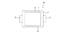
図1は、本発明を適用した非水系リチウム型蓄電素子100の一例を示す、模式図である。
一般に、蓄電素子は、正極、セパレータ、負極、電解液、及び外装体を主な構成要素とする。本発明の蓄電素子はリチウム塩を溶解させた有機溶媒(以下、「非水系電解液」という。)を電解液とする、非水系リチウム型蓄電素子100である。
Hereinafter, an example of an embodiment of the present invention will be described in detail.
FIG. 1 is a schematic diagram showing an example of a non-aqueous
In general, a power storage element mainly includes a positive electrode, a separator, a negative electrode, an electrolytic solution, and an outer package. The electricity storage device of the present invention is a non-aqueous lithium
本発明を適用した非水系リチウム型蓄電素子100は、図1にその一態様を示すように、正極および負極がセパレータを介して積層されてなる電極積層体1と、外装体21と、図示しない電解液と、負極端子用リードタブ22と、正極端子用リードタブ23と、で構成される。外装体21はラミネートフィルム等で構成され、ヒートシールにより密封するようになっている。前記電極積層体1および図示しない電解液は、外装体21内に収納され、電極積層体1はラミネート外装体カップ部24内に配置されている。
A non-aqueous
負極端子用リードタブ22は、一端が電極積層体1の図示しない負極に接続され、他端が外装体21の外部にラミネート外装体シール部25を介して引き出されている。正極端子用リードタブ23は、一端が電極積層体1の図示しない正極に接続され、他端が外装体21の外部にラミネート外装体シール部25を介して引き出されている。
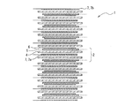
リチウムプリドープ前の電極積層体1は、図2に示すように、セパレータ4を介して、負極5および正極7が交互に積層され、負極5の一方の面にはさらに金属リチウム箔6が張り付けられている。
One end of the negative
As shown in FIG. 2, the electrode laminate 1 before lithium pre-doping has
また、セパレータ4、負極5および正極7は略矩形状に形成され、その結果、電極積層体1は略四角柱形状を有する。そして、前記負極端子用リードタブ22および正極端子用リードタブ23は、略四角柱形状の電極積層体1の対向する2辺に対応する位置にそれぞれ配置されている。なお、負極端子用リードタブ22および正極端子用リードタブ23の配置位置はこれに限るものではなく、電極積層体1の同一の辺に対応する位置に配置してもよく、任意の位置に配置することができる。
Moreover, the
ここで、正極7は、正極集電体の片面または両面上に正極活物質層を形成することによって作製することができる。
通常、電極積層体1の両端以外に配置される正極7は両面正極7aとなる。電極積層体1の両端に配置される正極7は片面正極7bおよび両面正極7aのどちらでもよいが、片面正極7bであることがスペース効率上好ましい。前記正極集電体は金属箔であることが好ましく、さらに、1μm以上80μm以下の厚みのアルミニウム箔であることが好ましい。本発明の実施の形態においては、正極集電体は貫通孔がないものが使用される。
Here, the positive electrode 7 can be produced by forming a positive electrode active material layer on one or both surfaces of the positive electrode current collector.
Usually, the positive electrode 7 disposed on both sides of the electrode laminate 1 is a double-sided positive electrode 7a. Although the positive electrode 7 arrange | positioned at the both ends of the electrode laminated body 1 may be either the single-sided positive electrode 7b and the double-sided positive electrode 7a, the single-sided positive electrode 7b is preferable on space efficiency. The positive electrode current collector is preferably a metal foil, and more preferably an aluminum foil having a thickness of 1 μm to 80 μm. In the embodiment of the present invention, a positive electrode current collector having no through hole is used.
正極活物質層は正極活物質と結着剤とを含有し、必要に応じて導電性フィラーを含有する。前記正極活物質としては、炭素質材料や結晶性が低くアモルファス状態のMnO2などの遷移金属酸化物、LiCoO2などのリチウム含有遷移金属酸化物が好ましく、さらには、BET比表面積が1000m2/g以上3000m2/g以下の活性炭であることが好ましい。 The positive electrode active material layer contains a positive electrode active material and a binder, and optionally contains a conductive filler. As the positive electrode active material, a carbonaceous material, a transition metal oxide such as MnO 2 having low crystallinity and an amorphous state, and a lithium-containing transition metal oxide such as LiCoO 2 are preferable, and a BET specific surface area of 1000 m 2 / It is preferable that it is activated carbon more than g and 3000 m < 2 > / g.
活性炭を正極活物質に用いる場合には、所望の特性を発揮する限りその原料などに特に制限は無く、石油系、石炭系、植物系、または高分子系などの各種の原料から得られた市販品を使用することができる。
活性炭を正極活物質として使用するときには、そのBET比表面積は重要であり、1000m2/g未満では単位重量あたりの容量が小さくなり、入出力特性も低下するため好ましくない。また、3000m2/gより大きくなると、単位重量あたりの容量は大きくなり、入力特性も良好ではあるものの、かさ高くなり、電極としたときの単位容積あたりの容量が低下するため好ましくない。
When activated carbon is used as the positive electrode active material, there is no particular limitation on the raw material as long as the desired characteristics are exhibited, and commercial products obtained from various raw materials such as petroleum-based, coal-based, plant-based, or polymer-based are available. Goods can be used.
When activated carbon is used as the positive electrode active material, the BET specific surface area is important. If the activated carbon is less than 1000 m 2 / g, the capacity per unit weight is decreased, and the input / output characteristics are also deteriorated. On the other hand, if it exceeds 3000 m 2 / g, the capacity per unit weight becomes large and the input characteristics are good, but it becomes bulky and the capacity per unit volume when used as an electrode is lowered, which is not preferable.
正極活物質の平均粒径は、1μm以上30μm以下が好ましく、1μm以上15μm以下である事がより好ましい。平均粒径が30μmより大きいと、電極作製、特に塗布方法による電極作製が困難になり、平均粒径が1μmより小さいと塗布および固着させるために必要な結着剤が多く必要になるため、エネルギー密度が低下する。
上記正極活物質には、必要に応じて導電性炭素材料からなる導電性フィラーを混合する事ができる。このような導電性フィラーとしては、ケッチェンブラック(登録商標)、アセチレンブラック、気相成長炭素繊維、黒鉛、これらの混合物などが好ましい。正極活物質層における導電性フィラーの含有量は、正極活物質と導電性フィラーおよび結着剤等の固形材料成分の合計量100質量%に対して0質量%以上30質量%以下が好ましく、1質量%以上20質量%以下の範囲がさらに更に好ましい。
The average particle diameter of the positive electrode active material is preferably 1 μm or more and 30 μm or less, and more preferably 1 μm or more and 15 μm or less. If the average particle size is larger than 30 μm, it is difficult to produce an electrode, particularly an electrode by a coating method. If the average particle size is smaller than 1 μm, a large amount of binder is required for coating and fixing. Density decreases.
The positive electrode active material can be mixed with a conductive filler made of a conductive carbon material as necessary. As such a conductive filler, ketjen black (registered trademark), acetylene black, vapor grown carbon fiber, graphite, a mixture thereof and the like are preferable. The content of the conductive filler in the positive electrode active material layer is preferably 0% by mass or more and 30% by mass or less with respect to 100% by mass of the total amount of the solid material components such as the positive electrode active material, the conductive filler, and the binder. A range of not less than 20% by mass and not more than 20% by mass is still more preferable.
導電性フィラーは高入力の観点からは混合した方が好ましいが、含有量が30質量%よりも多いと正極活物質層における正極活物質の含有量が少なくなるために、体積あたりのエネルギー密度が低下するので好ましくない。
正極活物質、更に必要に応じて添加された導電性フィラー(以下、これらをまとめて「正極合材」と呼ぶ。)を正極活物質層として正極集電体の上に塗布固着させるための結着剤としては、PVdF(ポリフッ化ビニリデン)、PTFE(ポリテトラフルオロエチレン)、フッ素ゴム、スチレン−ブタジエン共重合体、などを使用することができる。正極活物質層における結着剤の含有量は、正極活物質、導電性フィラーおよび結着剤等の固形材料成分の合計量100質量%に対して3質量%以上20質量%以下が好ましく、5質量%以上15質量%以下の範囲が更に好ましい。結着剤の含有量が20質量%よりも多いと正極活物質の表面を結着剤が覆ってしまい、イオンの出入りが遅くなり高出力が得られなくなるため好ましくない。また、結着剤の含有量が3質量%未満であると、正極合材を充分な接着強度で正極集電体に固着させる事ができなくなる。そのため、正極活物質層と正極集電体の接触抵抗が大きくなり高出力が得られにくくなったり、正極合材が電極加工中に脆く崩れて蓄電素子が作れなくなったり、こぼれた正極合材が蓄電素子の内部短絡の原因になったりするため好ましくない。
The conductive filler is preferably mixed from the viewpoint of high input. However, if the content is more than 30% by mass, the content of the positive electrode active material in the positive electrode active material layer is reduced, so that the energy density per volume is low. Since it falls, it is not preferable.
A positive electrode active material, and a conductive filler added as necessary (hereinafter collectively referred to as “positive electrode mixture”) as a positive electrode active material layer are coated and fixed on the positive electrode current collector. As the adhesive, PVdF (polyvinylidene fluoride), PTFE (polytetrafluoroethylene), fluororubber, styrene-butadiene copolymer, or the like can be used. The content of the binder in the positive electrode active material layer is preferably 3% by mass or more and 20% by mass or less with respect to 100% by mass of the total amount of solid material components such as the positive electrode active material, the conductive filler, and the binder. The range of not less than 15% by mass and more preferably not more than 15% by mass. When the content of the binder is more than 20% by mass, it is not preferable because the surface of the positive electrode active material is covered with the binder, and ions enter and exit slowly and a high output cannot be obtained. Further, when the content of the binder is less than 3% by mass, the positive electrode mixture cannot be fixed to the positive electrode current collector with sufficient adhesive strength. As a result, the contact resistance between the positive electrode active material layer and the positive electrode current collector increases, making it difficult to obtain a high output, or the positive electrode mixture becomes brittle during electrode processing, making it impossible to produce a storage element, or a spilled positive electrode mixture This is not preferable because it may cause an internal short circuit of the electric storage element.
この他、正極合材の粘度調整を目的として、増粘剤や分散剤を混合する事もある。例えば、ポリビニルピロリドンなどがその代表例として挙げられ、一般的には、正極活物質、導電性フィラーおよび結着剤等の固形材料成分の合計量100質量%に対して1質量%以上5質量%以下程度が好ましい。
正極7は、正極合材と結着剤等とを溶媒に分散させたペーストを作製し、このペーストを正極集電体上に塗布し、乾燥させ、必要に応じてプレスして正極活物質層を形成する事で得られる。塗布方法は、ペーストの物性および塗布厚に応じて適宜選択することができる。また、溶媒を使用せずに乾式で正極合材と結着剤とを混合してプレス成型して活物質層とし、これを正極集電体に導電性結着剤を使用して貼り付ける事も可能である。これら正極活物質層の厚みは、通常30μm以上200μm以下程度が好ましい。厚みが30μm未満であると、蓄電素子の内部が集電体およびセパレータばかりになり、全体としての活物質の割合が低減するため、該蓄電素子の容量あたりのエネルギー密度が低下する。また厚みが200μmよりも厚くなると、蓄電素子は高エネルギー密度になるが、数秒という時間で使用したときの入出力特性が低下する。
In addition, a thickener or a dispersant may be mixed for the purpose of adjusting the viscosity of the positive electrode mixture. For example, polyvinyl pyrrolidone and the like are listed as typical examples. Generally, it is 1% by mass or more and 5% by mass with respect to 100% by mass of the total amount of solid material components such as a positive electrode active material, a conductive filler and a binder. The following degree is preferable.
For the positive electrode 7, a paste in which a positive electrode mixture and a binder are dispersed in a solvent is prepared, and this paste is applied on a positive electrode current collector, dried, and pressed as necessary to form a positive electrode active material layer It is obtained by forming. The coating method can be appropriately selected according to the physical properties of the paste and the coating thickness. In addition, dry mix without using a solvent and mix the positive electrode mixture and the binder and press-mold them to form an active material layer, which is then affixed to the positive electrode current collector using a conductive binder. Is also possible. The thickness of these positive electrode active material layers is usually preferably about 30 μm or more and 200 μm or less. When the thickness is less than 30 μm, the inside of the electricity storage element is only the current collector and the separator, and the ratio of the active material as a whole is reduced, so that the energy density per capacity of the electricity storage element is lowered. When the thickness is greater than 200 μm, the energy storage device has a high energy density, but the input / output characteristics when used in a time of several seconds are degraded.
一方、負極5は、負極集電体の片面または両面上に負極活物質層を形成することによって作製することができる。本発明においては、負極5は、負極活物質層が負極集電体の両面に形成される両面負極である。なお、以下、負極5または両面負極5という。
そして、負極5および正極7は、図2に示すように、負極5の片面の負極活物質層はセパレータ4を介して正極7の正極活物質層と対向し、負極5の他方の面の負極活物質層はこの負極5に張り付けられた金属リチウム箔6およびセパレータ4を順次介して正極7の正極活物質層と対向するように配置されている。
On the other hand, the
As shown in FIG. 2, the
本発明の実施の形態においては、貫通孔を有する負極集電体を用いる事が特徴であり、負極5の片面の負極活物質層に圧着された上記金属リチウム箔6によって、負極集電体の両面に形成された負極活物質層全体に均一にリチウムイオンを供給する事が可能となる。これにより、負極活物質層の片面に供給されたリチウムイオン量を負極集電体が孔を有さない場合の半分とすることができるため、Liイオンを吸収すべき片面あたりの負極活物質層の厚さを負極集電体が貫通孔を有さない場合の半分にする事が可能となり、高入出力の蓄電素子を実現できる。また、工業生産的にも、金属リチウム箔を両面に圧着する必要がないことから製造工程の簡略化が可能である。負極集電体が有する貫通孔の形状は、円、楕円、多角形など、どのような形状でも良いが、貫通している孔であることが重要である。
The embodiment of the present invention is characterized in that a negative electrode current collector having a through hole is used, and the negative electrode current collector is formed by the
負極集電体は片面から逆面に貫通する貫通孔を有する1μm以上100μm以下の厚みの金属箔であり、好ましくは、空隙率が10%以上70%以下の銅箔である。貫通孔の大きさは当該空隙率を満たす範囲で、小さくかつ均一に分布している事がより好ましい。ここでいう空隙率は重量法で測定される空隙率である。銅の真比重は8.93g/cm3であるが、空隙があることによって同一の大きさの銅箔であっても重量が異なる事を利用して算出する。これは例えば、集電体を2cm×5cmの大きさに切り出し、その厚みをマイクロメーターで測定し、幾何体積を求め、電子天秤でその重量を測定することで、集電体のみかけ比重を算出し、真比重との比から求める事ができる。 The negative electrode current collector is a metal foil having a thickness of 1 μm or more and 100 μm or less having a through hole penetrating from one side to the opposite side, and preferably a copper foil having a porosity of 10% or more and 70% or less. It is more preferable that the size of the through holes is small and uniformly distributed as long as the porosity is satisfied. The porosity here is a porosity measured by a gravimetric method. The true specific gravity of copper is 8.93 g / cm 3 , but it is calculated using the fact that the weight is different even for copper foils of the same size due to the presence of voids. For example, a current collector is cut into a size of 2 cm × 5 cm, its thickness is measured with a micrometer, a geometric volume is obtained, and its weight is measured with an electronic balance, thereby calculating the apparent specific gravity of the current collector. However, it can be obtained from the ratio to the true specific gravity.
ただし、エキスパンドメタルのような波型の断面形状を有する集電体を用いる場合には、厚みはマイクロメーターでは正確に測定できないため、光学顕微鏡やレーザー顕微鏡、電子顕微鏡などで実際の板厚、すなわち、エキスパンドする前の板厚を見積もる事で上記の重量法を適用して算出する。
空隙率が10%未満であると、片面の負極活物質層側から供給されるリチウムイオンの濃度が、両面の活物質層間で均一になりにくく、金属リチウム箔6の負極活物質層への吸収に時間がかかったり、負極活物質層中のリチウムイオン濃度の不均一が生じたりするため好ましくない。また、両面の活物質層間でリチウムイオンの濃度が均一になる時間を短縮させるためには、空隙率が高い程好ましいが、70%よりも高いと集電体、さらには負極5の機械的な強度を確保する事が難しく、特に塗布方法で電極を作製することが困難になり、電極としての取り扱いが困難になる。
However, when using a current collector with a corrugated cross-sectional shape such as expanded metal, the thickness cannot be measured accurately with a micrometer, so the actual plate thickness with an optical microscope, laser microscope, electron microscope, etc. The above weight method is applied by estimating the plate thickness before expanding.
When the porosity is less than 10%, the concentration of lithium ions supplied from the negative electrode active material layer side on one side is less likely to be uniform between the active material layers on both sides, and absorption into the negative electrode active material layer of the
負極活物質層は負極活物質と結着剤を含有し、必要に応じて導電性フィラーを含有する。負極活物質は、リチウムイオンを吸蔵可能な低温焼成コークス、難黒鉛性カーボン、および活性炭に非晶質カーボンを吸着させた複合多孔性材料などの非黒鉛多孔質材料(以下、「リチウムイオン吸蔵可能炭素材料」という。)であってBET法による比表面積が1m2/g以上1500m2/g以下のものが好ましい。上記の複合多孔性材料は本発明の負極5として、より好適な材料である。
The negative electrode active material layer contains a negative electrode active material and a binder, and optionally contains a conductive filler. Negative electrode active materials include non-graphite porous materials such as low-temperature calcined coke that can occlude lithium ions, non-graphite carbon, and composite porous materials in which amorphous carbon is adsorbed on activated carbon (hereinafter “lithium ion occlusion is possible”). The carbon material is preferably a material having a specific surface area of 1 m 2 / g or more and 1500 m 2 / g or less by the BET method. Said composite porous material is a more suitable material as the
アセチレンブラック、カーボンブラックなど、BET法による比表面積が1500m2/gを超える活性炭は本発明の実施態様で使用する負極活物質としては好ましくない。また、天然黒鉛、人造黒鉛のような黒鉛は、急速充電特性に劣るため、高出力は達成できても高入力を有する蓄電素子にならないため本発明の負極活物質としては好ましくない。これは、黒鉛系炭素材料はリチウムイオンの吸蔵および放出をリチウム金属の酸化還元電位に近い電位で行うため、急速充電時にはリチウム金属の酸化還元電位を下回り、デンドライト状にリチウムが析出して、容量低下、長期の安定性が低下するためである。 Activated carbon having a specific surface area of more than 1500 m 2 / g by the BET method, such as acetylene black and carbon black, is not preferable as the negative electrode active material used in the embodiment of the present invention. In addition, graphite such as natural graphite and artificial graphite is not preferable as the negative electrode active material of the present invention because it is inferior in quick charge characteristics and does not become a power storage device having high input even if high output can be achieved. This is because graphite-based carbon materials absorb and release lithium ions at a potential close to the redox potential of lithium metal. This is because the long-term stability is lowered.
負極活物質として、上記リチウムイオン吸蔵可能炭素材料のなかでも、初回の充電量が500mAh/g以上1500mAh/g以下である炭素質材料が好ましい。このような炭素質材料としては、難黒鉛性または易黒鉛性の炭素材料を1000℃以下の低温で焼成した低温焼成炭素、活性炭に非晶質カーボンを吸着させた複合多孔性材料などの非黒鉛炭素質材料をあげることができる。 As the negative electrode active material, a carbonaceous material having an initial charge amount of 500 mAh / g or more and 1500 mAh / g or less is preferable among the above-described lithium ion storable carbon materials. Examples of such carbonaceous materials include non-graphite such as low-temperature calcined carbon obtained by calcining non-graphitizable or easily graphitizable carbon material at a low temperature of 1000 ° C. or lower, and composite porous material obtained by adsorbing amorphous carbon on activated carbon. Carbonaceous materials can be raised.
初回の充電容量が500mAh/g以上であるリチウムイオン吸蔵可能炭素材料は、一般に初期のリチウムイオンの損失が初回の充電容量の30%以上と大きいために、系内に金属リチウムを導入する効果が大きく、リチウムイオンの吸蔵および放出を行う電位が黒鉛のようにリチウム金属の酸化還元電位近傍だけではないため、高出力さらには高入力の蓄電素子を実現できる。また、初回の充電容量が1500mAh/gを超えるような材料、例えば、複合化処理をしていない活性炭そのものは、充電による体積膨張が大きくなるため電極が剥離したり、炭素質材料そのものが粉砕されたりするため好ましくない。 Lithium ion storage-capable carbon materials having an initial charge capacity of 500 mAh / g or more are generally effective in introducing metallic lithium into the system because the initial lithium ion loss is as large as 30% or more of the initial charge capacity. Since the potential for inserting and extracting lithium ions is not only near the oxidation-reduction potential of lithium metal like graphite, a high-output and high-input power storage device can be realized. In addition, materials whose initial charge capacity exceeds 1500 mAh / g, such as activated carbon that has not been subjected to the composite treatment, have a large volume expansion due to charging, so that the electrode peels off or the carbonaceous material itself is crushed. Is not preferable.
上記リチウムイオン吸蔵可能炭素材料の形状は、平均粒径が1μm以上30μm以下程度のものが好ましく、1μm以上15μm以下のものがより好ましい。
負極活物質のBET法による比表面積は1m2/g以上1500m2/g以下である事が好ましく、10m2/g以上1200m2/g以下がより好ましく、20m2/g以上1000m2/g以下が更に好ましい。比表面積が1m2/gより小さいと大電流による放電や充電が出来なくなるという問題が発生し、比表面積が1500m2/gより大きいと嵩高くなり、電極化した時の単位体積あたりの容量が低下するため、蓄電素子の高エネルギー密度化が困難になる。
The shape of the lithium ion storable carbon material preferably has an average particle diameter of about 1 μm to 30 μm, and more preferably 1 μm to 15 μm.
The specific surface area by the BET method of the negative electrode active material is preferably 1 m 2 / g or more and 1500 m 2 / g or less, more preferably 10 m 2 / g or more and 1200 m 2 / g or less, and 20 m 2 / g or more and 1000 m 2 / g or less. Is more preferable. If the specific surface area is less than 1 m 2 / g, there is a problem that discharging and charging due to a large current cannot be performed. If the specific surface area is greater than 1500 m 2 / g, the bulk becomes high, and the capacity per unit volume when the electrode is formed becomes large. Therefore, it is difficult to increase the energy density of the power storage element.
上記負極活物質層には、負極活物質以外に、必要に応じて負極活物質より導電性の高い炭素質材料からなる導電性フィラーを混合することができる。該導電性フィラーとしては、アセチレンブラック、ケッチェンブラック、気相成長炭素繊維、および、これらの混合物をあげることができる。該導電性フィラーの含有量は、負極活物質と導電性フィラー、結着剤等の固形材料成分の合計量100質量%に対して0質量%以上30質量%以下が好ましく、1質量%以上20質量%以下の範囲がさらに好ましい。導電性フィラーは高入力の観点からは混合したほうが好ましいが、含有量が30質量%よりも多いと負極活物質層における負極活物質の含有量が少なくなるために、体積あたりのエネルギー密度が低下するので好ましくない。 In addition to the negative electrode active material, a conductive filler made of a carbonaceous material having higher conductivity than the negative electrode active material can be mixed in the negative electrode active material layer as necessary. Examples of the conductive filler include acetylene black, ketjen black, vapor grown carbon fiber, and mixtures thereof. The content of the conductive filler is preferably 0% by mass or more and 30% by mass or less, and preferably 1% by mass or more and 20% by mass or less with respect to 100% by mass of the total amount of solid material components such as the negative electrode active material, the conductive filler, and the binder. A range of less than or equal to mass% is more preferred. The conductive filler is preferably mixed from the viewpoint of high input, but if the content is more than 30% by mass, the content of the negative electrode active material in the negative electrode active material layer is reduced, so the energy density per volume is reduced. This is not preferable.
負極活物質および、必要に応じて混合された導電性フィラー(以下、これらをあわせて「負極合材」と呼ぶ。)を負極集電体に固着させるための結着剤としては、PVdF、スチレン−ブタジエン共重合体などを使用することができる。負極活物質層における結着剤の混合量は、負極活物質と導電性フィラー、結着剤等の固形材料成分の合計量100質量%に対して3質量%以上20質量%以下が好ましく、5質量%以上15質量%以下の範囲がさらに好ましい。結着剤の混合量が20質量%よりも多いと負極活物質の表面を結着剤が覆ってしまい、イオンの出入りが遅くなり高出力が得られなくなるため好ましくない。また、結着剤の混合量が3質量%未満であると、負極合材を充分な接着強度で負極集電体に固着させることができなくなり、負極活物質層と負極集電体の接触抵抗が大きくなり高出力が得られにくくなったり、こぼれた負極合材が素子の内部短絡の原因になったりするため好ましくない。 PVdF, styrene may be used as a binder for fixing the negative electrode active material and, if necessary, a mixed conductive filler (hereinafter, collectively referred to as “negative electrode mixture”) to the negative electrode current collector. -Butadiene copolymer etc. can be used. The mixing amount of the binder in the negative electrode active material layer is preferably 3% by mass or more and 20% by mass or less with respect to 100% by mass of the total amount of the solid material components such as the negative electrode active material, the conductive filler, and the binder. The range of not less than 15% by mass and more is more preferable. When the amount of the binder mixed is more than 20% by mass, the surface of the negative electrode active material is covered with the binder, which is not preferable because ions enter and exit slowly and high output cannot be obtained. Further, if the mixing amount of the binder is less than 3% by mass, the negative electrode mixture cannot be fixed to the negative electrode current collector with sufficient adhesive strength, and the contact resistance between the negative electrode active material layer and the negative electrode current collector This is not preferable because the high power becomes difficult to obtain, and a spilled negative electrode mixture causes an internal short circuit of the device.
負極5は、負極合材と結着剤とを溶媒に分散させたペーストを作製し、このペーストを負極集電体上に塗布し、乾燥させて、必要に応じてプレスして負極活物質層を成型することにより得られる。また、溶媒を使用せずに乾式で負極合材と結着剤とを混合してプレス成型して活物質層とし、これを負極集電体に導電性結着剤を使用して貼り付ける事も可能である。
The
使用する金属リチウム箔6の厚みは、20μm以上60μm未満が好適である。特殊用途向けである金属リチウム箔の厚みが20μmであるため、20μmより薄い金属リチウム箔は工業的に入手することが不可能である。
また、60μm以上の金属リチウム箔を使用する場合には、工業的に入手可能な30μmの金属リチウム箔を従来通りに貫通孔を有さない負極集電体の両面に形成された負極活物質層の両面にそれぞれ圧着することで同等の効果を達成することが可能であり、1枚に代えて2枚圧着する必要があるため手間は掛かるものの、本願発明の効果が充分に奏されないからである。
The thickness of the
In addition, when a metal lithium foil of 60 μm or more is used, a negative electrode active material layer formed on both surfaces of a negative electrode current collector that does not have a through hole as in the case of an industrially available metal lithium foil of 30 μm. It is possible to achieve the same effect by crimping each of the two sides, and since it is necessary to crimp two sheets instead of one, it takes time, but the effect of the present invention is not fully achieved. .
上記負極活物質層の厚みは、20μm以上100μm以下が好ましい。20μm未満では電極を形成することが困難であり、更には蓄電素子の単位体積に含まれる活物質の量が低下するため、電極積層体の単位体積あたりのエネルギー密度が低下するため好ましくない。また、100μmを超えると、蓄電素子の単位体積あたりに含まれる電極面積が低減すると共に、電極の厚みによる電気抵抗の上昇や、リチウムイオンの拡散距離の増大によって蓄電素子の高出力化が阻害されるため好ましくない。 The thickness of the negative electrode active material layer is preferably 20 μm or more and 100 μm or less. If it is less than 20 μm, it is difficult to form an electrode, and further, the amount of the active material contained in the unit volume of the electricity storage element is lowered, so that the energy density per unit volume of the electrode laminate is lowered, which is not preferable. In addition, when the thickness exceeds 100 μm, the electrode area contained per unit volume of the power storage element is reduced, and an increase in the output of the power storage element is hindered by an increase in electrical resistance due to the thickness of the electrode and an increase in the diffusion distance of lithium ions. Therefore, it is not preferable.
本発明において、負極集電体の両面に存在する負極活物質層の片面、単位面積あたりの初回の充電電気量B(mAh/cm2)と金属リチウム箔の厚みA(μm)とは、「0.07≦B/A≦0.103」なる関係式を満足していることが好ましい。
ここで、厚み1μmの金属リチウム箔6は単位面積あたり約0.206mAh/cm2の電気量(リチウムの分子量6.94、密度0.534g/cm3から計算された電気量。)に相当する。本発明においては負極集電体が貫通孔を有するため、これが両面の負極活物質層に供給されることになる。したがって片面あたりは0.103mAh/cm2である。このため、「B/A」が「0.103」を超えると金属リチウム箔6が完全に負極活物質層にリチウムイオンとして吸蔵されることがなく、リチウム金属のまま系に残るため、サイクルによる容量低下や長期安定性の低下などを引き起こすため好ましくない。また、初回の充電電気量0.103の3/4に相当する0.077未満のリチウムイオンを導入した場合には、初期のリチウムイオンの損失を充分補うことができず、そのため蓄電素子を充電したときに負極の電位を金属リチウムの酸化還元電位付近まで下げることが困難になり、その結果として蓄電素子の高電圧化が難しくなることから、蓄電素子のエネルギー密度が低下したり、無理に蓄電素子の電圧を上げると正極の電位が高くなりすぎて電解液の分解が起きるなどしたりして、長期の安定性の点で好ましくない。
In the present invention, one side of the negative electrode active material layer present on both sides of the negative electrode current collector, the initial charge amount B (mAh / cm 2 ) per unit area and the thickness A (μm) of the metal lithium foil are: It is preferable that the relational expression “0.07 ≦ B / A ≦ 0.103” is satisfied.
Here, the
なお、負極活物質層の単位面積あたりの初回の充電電気量B(mAh/cm2)は、該負極活物質層が片面に形成された電極を適切な、例えば2cm2程度の大きさに切り出し、リチウム金属を対極、リチウム金属を参照極とした3極式のセルを作成し、最小電圧1mVに設定して24時間リチウムを吸蔵させた電気量を、測定に使用した負極面積で割ることで求めることができる。 The initial charge electricity quantity B (mAh / cm 2 ) per unit area of the negative electrode active material layer is determined by cutting an electrode having the negative electrode active material layer formed on one side into a suitable size, for example, about 2 cm 2. By creating a tripolar cell with lithium metal as the counter electrode and lithium metal as the reference electrode, dividing the quantity of electricity stored in the lithium for 24 hours with the minimum voltage set to 1 mV, divided by the negative electrode area used for the measurement Can be sought.
本発明においては、金属リチウム箔6の厚みとあらかじめ負極活物質に吸蔵させたいリチウムイオンの量を勘案すれば、片面に形成された負極活物質の単位面積あたりの担持量が決定される。例示すれば、たとえば負極活物質にあらかじめ約500mAh/g相当のリチウム量を吸蔵させることを目的として、30μmの金属リチウム箔を使用する場合を考える。30μmの金属リチウム箔は1cm2あたり約6.18mAhの電気量(リチウムの分子量6.94、密度0.534g/cm3から計算された電気量。)に相当するから、これが両面の負極活物質に吸蔵されるので片面あたりの電気量は約3.09mAhになる。したがって、「3.09mAh÷500mAh/g≒6.18mg」となり、片面1cm2あたり約6.18mgの負極活物質が担持された電極を作成すればよいことになる。仮に負極活物質層における活物質の含有量が90質量%であって、負極の嵩密度が0.7g/cm3であった場合には、片面あたり、「0.00618÷0.7÷0.9=0.0098cm=98μm」の負極活物質層を有する負極を作成すればよい。
In the present invention, if the thickness of the
負極集電体に貫通孔がない場合には、入手できる特殊用途の20μmの金属リチウム箔を使用したとしても、1cm2あたり約4.12mAhの電気量に相当するから、「4.12÷500mAh/g≒8.24mg」となり、先の活物質の含有量と嵩密度とから、「0.00824÷0.7÷0.9=131μm」、すなわち、本発明に対して約1.33倍の厚みの負極活物質層が必要になる。さらに、工業的に使用できる30μmの金属リチウム箔を使用するとして同様に計算すると、片面196μm、すなわち、本発明に対して約2倍の厚みの負極活物質層が必要となる。負極活物質層の厚みが2倍になると、それに対応した正極活物質層の厚みも2倍になり、蓄電素子を構成する電極群の面積が極端に減少するため、大電流を流すことが困難になり、出力特性が悪い蓄電素子となる。なお、リチウムをあらかじめ添加しないと容量が著しく低下するため、蓄電素子として実用に耐えない。 If the negative electrode current collector does not have a through hole, even if a 20 μm metal lithium foil for special use is available, it corresponds to an amount of electricity of about 4.12 mAh per 1 cm 2 , so that “4.12 ÷ 500 mAh” /G≈8.24 mg ”, and“ 0.00824 ÷ 0.7 ÷ 0.9 = 131 μm ”from the content of the active material and the bulk density, that is, about 1.33 times the present invention. A negative electrode active material layer having a thickness of 5 mm is required. Further, if the same calculation is made assuming that a 30 μm metallic lithium foil that can be used industrially is used, a negative electrode active material layer having a thickness of 196 μm on one side, that is, about twice that of the present invention is required. When the thickness of the negative electrode active material layer is doubled, the thickness of the corresponding positive electrode active material layer is also doubled, and the area of the electrode group constituting the power storage element is extremely reduced, so that it is difficult to flow a large current. Thus, the power storage element having poor output characteristics is obtained. Note that if lithium is not added in advance, the capacity is remarkably reduced, so that it cannot be practically used as a power storage element.
このように、負極集電体に貫通孔を形成することで、リチウム金属によって容量低下を防止しながら工業的に量産可能な、高容量、高出力な蓄電素子を実現できる。
リチウムイオン二次電池などでは、組み立て時の精度ばらつきを考慮して、通常、負極よりも正極の方が周囲約0.5mm程度小さく、正極を負極が覆い隠すような積層構造をしている。本発明の蓄電素子でも正極を負極が覆い隠すような構造が好ましい。
Thus, by forming a through-hole in the negative electrode current collector, a high-capacity and high-output power storage element that can be industrially mass-produced while preventing a decrease in capacity by lithium metal can be realized.
In consideration of variation in accuracy during assembly, a lithium ion secondary battery or the like usually has a laminated structure in which the positive electrode is smaller than the negative electrode by about 0.5 mm in circumference and the positive electrode is covered with the negative electrode. The power storage device of the present invention preferably has a structure in which the negative electrode covers the negative electrode.
本発明において、負極5の負極活物質層と金属リチウム箔6との位置関係は、図3(a)のように、負極5の負極活物質層部分よりも一回り小さく、負極活物質層の、正極7の正極活物質層と対向する部分に圧着してもよく、また、図3(b)のように負極5の負極活物質層部分を覆い尽くすように全面に圧着してもよい。また、図3(c)に示すように、負極活物質層部分に対して金属リチウム箔6が、圧着時に多少ずれたとしてもよく、金属リチウム箔6が負極5からはみ出さないように圧着すればよい。このように、負極5の負極活物質層全面からリチウムイオンを供給することにより、従来必要であったプリドープ時間を大幅に短縮することが可能になる。
In the present invention, the positional relationship between the negative electrode active material layer of the
すなわち、ストライプ状にリチウムイオンを供給したり、負極活物質の一部にリチウムイオンを過剰供給したり、集電体などからリチウムイオンを供給しようとすると、負極活物質間でリチウムイオンの濃度を均一にするために多くの時間がかかる。これは、拡散距離を考えれば容易に理解されることであるが、全面から供給すれば、リチウムイオンの均一化は電極厚み方向、すなわち高々200μmの間で行われるが、全面以外からの供給であると、電極内の厚み方向だけでなく、面方向の数mmから数十cmの間で均一化が行われなければならないためである。 That is, if lithium ions are supplied in stripes, lithium ions are excessively supplied to a part of the negative electrode active material, or lithium ions are supplied from a current collector, the concentration of lithium ions between the negative electrode active materials is reduced. It takes a lot of time to make it uniform. This is easily understood in view of the diffusion distance, but if supplied from the entire surface, the lithium ions are homogenized in the electrode thickness direction, that is, at most 200 μm. This is because uniformization must be performed not only in the thickness direction in the electrode but also in the plane direction from several mm to several tens of cm.
金属リチウム箔6の負極5への圧着方法は、アルゴンなどの不活性ガス下で平板プレス、ロールプレスなど、通常のプレス方法によって行われる。なお、圧着前には負極5を真空乾燥して水分を除去しておくことが好ましい。
負極集電体の両面に負極活物質層を有し、かつ片面の負極活物質層上に金属リチウム箔6が圧着された負極5は、その両面がセパレータ4を介して正極7と対向するように積層されて例えばラミネートフィルムから形成された外装体21に挿入される。
The pressure bonding method of the
The
正極、負極、セパレータを積層する際には、両面負極の上面となる面に前記金属リチウム箔が圧着された両面負極と、両面負極の下面となる面に前記金属リチウム箔が圧着された両面負極とを含むように、両面正極と前記両面負極とをセパレータを介して交互に積層する。
好ましくは、図2に示すように、負極(両面負極)5と両面正極7aとセパレータ4とを、負極(両面負極)5/セパレータ4/両面正極7a/セパレータ4/負極(両面負極)5の順に積層した部分電極積層体2を1つ以上含むように、正極7、負極5、及びセパレータ4を積層することで電極積層体1を作製する。また、通常、電極積層体1の両端以外に配置される正極は両面正極7aを用いる。また、電極積層体1の両端に配置される正極は両面正極7aおよび片面正極7bのいずれであっても適用することができるが、スペース効率上、片面正極7bを用いることが望ましい。
When laminating a positive electrode, a negative electrode, and a separator, a double-sided negative electrode in which the metal lithium foil is pressure-bonded to the surface that becomes the upper surface of the double-sided negative electrode, and a double-sided negative electrode in which the metal lithium foil is pressure-bonded to the surface that becomes the lower surface of the double-sided negative electrode The double-sided positive electrode and the double-sided negative electrode are alternately stacked via separators.
Preferably, as shown in FIG. 2, the negative electrode (double-sided negative electrode) 5, the double-sided positive electrode 7 a, and the
また、この電極積層体1を作製する工程においては、図2に示すように、前記電極積層体1に含まれる負極(両面負極)5に圧着された金属リチウム箔6の圧着方向が、セパレータ4及び両面正極7aを介して隣接する負極(両面負極)5に圧着されている金属リチウム箔6の圧着方向と、両面正極7aに対して面対称となる部分電極積層体2を1組以上含むように積層する必要がある。
Moreover, in the process of producing this electrode laminated body 1, as shown in FIG. 2, the crimping | compression-bonding direction of the
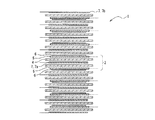
図2は、負極(両面負極)5を8枚有する電極積層体1において、8枚の負極5のうちの半数である4枚の負極5に貼り付けた金属リチウム箔6の圧着方向がその上面であるとともに隣接する負極5の金属リチウム箔6の圧着方向がその下面であり、両面正極7aに対して面対称となる方向となっている。つまり、各負極5において、金属リチウム箔6の圧着方向が交互に逆となっている。この場合、n番目の負極5とn+1番目の負極5とは、金属リチウム箔6の圧着方向が逆となり、これら負極5の間に積層されている両面正極7aに対して面対称となる。したがって、好ましい積層方法と言える。
FIG. 2 shows that in the electrode laminate 1 having eight negative electrodes (double-sided negative electrodes) 5, the pressing direction of the
逆に、例えば図8に示すように、負極(両面負極)5を8枚有する電極積層体1において、8枚全ての負極5に圧着された金属リチウム箔6の圧着方向がその下面となるように積層する積層方法(従来の積層方法の一例)の場合、いずれの負極5も、この負極5に圧着された金属リチウム箔6と、これに隣接するn+1番目の負極5の金属リチウム箔6とが両面正極7aに対して面対称の関係とはならない。したがって、この積層方法は好ましくない。
Conversely, for example, as shown in FIG. 8, in the electrode laminate 1 having eight negative electrodes (double-sided negative electrodes) 5, the crimping direction of the
また、例えば図4、図5、図6のような積層状態も好ましい積層方法の一例である。
図4は、負極(両面負極)5を8枚有する電極積層体1において、8枚の負極5のうち、上層側の4枚の負極5はその上面に金属リチウム箔6が圧着され、下層側の4枚の負極5はその下面に金属リチウム箔6が圧着されている。
したがって、上層から4番目の負極5、つまり上面に金属リチウム箔6が圧着された負極5と、5番目の負極5、つまり下面に金属リチウム箔6が圧着された負極5とは、これらに圧着された金属リチウム箔6が両面正極7aに対して面対称の位置関係となり、すなわち部分電極積層体2を構成する。
In addition, for example, a stacked state as shown in FIGS. 4, 5, and 6 is an example of a preferable stacking method.
FIG. 4 shows an electrode laminate 1 having eight negative electrodes (double-sided negative electrodes) 5. Of the eight
Therefore, the fourth
図5は、負極(両面負極)5を8枚有する電極積層体1において、8枚の負極5のうち、上層側の4枚の負極5はその下面に金属リチウム箔6が圧着され、下層側の4枚の負極5はその上面に金属リチウム箔6が圧着されている。
したがって、上層から4番目の負極5、つまり下面に金属リチウム箔6が圧着された負極5と、5番目の負極5、つまり上面に金属リチウム箔6が圧着された負極5とは、これらに圧着された金属リチウム箔6が両面正極7aに対して面対称の位置関係となり、すなわち部分電極積層体2を構成する。
FIG. 5 shows an electrode laminate 1 having eight negative electrodes (double-sided negative electrodes) 5. Of the eight
Accordingly, the fourth
図6は、負極(両面負極)5を8枚有する電極積層体1において、2枚の負極5毎に、金属リチウム箔6を圧着する方向を逆にしたものである。図6では、上層側から1番目、2番目、5番目、6番目の負極5についてはその下面に金属リチウム箔6が圧着され、3番目、4番目、7番目、8番目の負極5については、その上面に金属リチウム箔6が圧着されている。
FIG. 6 shows the electrode laminate 1 having eight negative electrodes (double-sided negative electrodes) 5 in which the direction in which the
したがって、上から2番目と3番目の負極5において、その金属リチウム箔6どうしが両面正極7aに対して面対称の位置関係となり、隣接する2枚の負極5毎に、その金属リチウム箔6どうしが両面正極7aに対して面対称の関係となる。つまり、部分電極積層体2が3組形成される。
したがって、図4から図6のいずれの積層方法も適用できる。なお、この他様々な圧着方向での積層形態が考えられるが、隣接する両面負極5の金属リチウム箔6の圧着方向が反対となる部分電極積層体2が1つ以上あれば良く、記載した図面の限りではない。
Accordingly, in the second and third
Therefore, any of the lamination methods shown in FIGS. 4 to 6 can be applied. In addition, although the lamination | stacking form in various crimping | compression-bonding directions can be considered, there should just be one or more partial electrode laminated
前述のように、リチウムイオンのプリドープによる負極5の膨潤のばらつきにより負極5にたわみが生じ、金属リチウム箔6が上面に配置された負極5と、金属リチウム箔6が下面に配置された負極5とにより、これら負極5におけるたわみが相殺されて電極積層体1全体におけるたわみが抑制されることになる。
したがって、要は、金属リチウム箔6が上面に配置された負極5と金属リチウム箔6が下面に配置された負極5とを含めば、少なくともこれら負極5におけるたわみは抑制されるため、金属リチウム箔6が上面に配置された負極5と金属リチウム箔6が下面に配置された負極5とを含むように、電極積層体1を構成すればよい。金属リチウム箔6が上面に配置された負極5の数と金属リチウム箔6が下面に配置された負極5の数とが同数または同数程度であるほど好ましく、具体的には、金属リチウム箔6が上面に配置された負極5の数と金属リチウム箔6が下面に配置された負極5の数との比が2:3以上3:2以下であることが好ましい。
As described above, the
Therefore, in summary, if the
また、実際の積層手順は、前述した両面負極5/セパレータ4/両面正極7a/セパレータ4/両面負極5からなる部分電極積層体を下層から上層へ順次積層する方法だけではなく、例えば、部分電極積層体の一部又は全部を含む積層体を複数個前工程で作製し後工程で該複数個の積層体を積層して1つの電極積層体とする方法や、該複数個の積層体を必要に応じて上下反転させながら積層させていく方法でも構わないため、積層手順、方法を限定するものではない。
In addition, the actual lamination procedure is not limited to the method of sequentially laminating the partial electrode laminate composed of the double-sided
セパレータ4はリチウムイオン二次電池に用いられるポリエチレン製の微多孔膜、もしくはポリプロピレン製の微多孔膜、または電気二重層コンデンサで用いられるセルロース製の不織紙などを用いることができる。セパレータの厚みは10μm以上50μm以下が好ましい。10μm未満の厚みでは、内部のマイクロショートによる自己放電が大きくなるため好ましくない。また、50μmより厚いと、当該電極積層体1を含んで構成される蓄電素子のエネルギー密度が減少するだけでなく、出力特性も低下するため好ましくない。
The
本発明の実施態様の蓄電素子に用いられる非水系電解液の溶媒としては、炭酸エチレン(EC)、炭酸プロピレン(PC)に代表される環状炭酸エステル、炭酸ジエチル(DEC)、炭酸ジメチル(DMC)、炭酸エチルメチル(MEC)に代表される鎖状炭酸エステル、γ−ブチロラクトン(γBL)などのラクトン類、ならびにこれらの混合溶媒を用いることができる。 Examples of the solvent of the non-aqueous electrolyte used in the electricity storage device of the embodiment of the present invention include cyclic carbonates represented by ethylene carbonate (EC) and propylene carbonate (PC), diethyl carbonate (DEC), and dimethyl carbonate (DMC). A chain carbonate represented by ethyl methyl carbonate (MEC), lactones such as γ-butyrolactone (γBL), and a mixed solvent thereof can be used.
これら溶媒に溶解する電解質はリチウム塩である必要があり、好ましいリチウム塩を例示すれば、LiBF4、LiPF6、LiN(SO2C2F5)2、LiN(SO2CF3)(SO2C2F5)およびこれらの混合塩をあげることができる。
非水系電解液中の電解質濃度は、0.5mol/L以上2.0mol/L以下の範囲が好ましい。0.5mol/L未満では陰イオンが不足して蓄電素子の容量が低下する。また、2.0mol/Lを超えると未溶解の塩が該電解液中に析出したり、該電解液の粘度が高くなりすぎたりすることによって、逆に伝導度が低下して出力特性が低下する。
The electrolyte dissolved in these solvents needs to be a lithium salt. For example, LiBF 4 , LiPF 6 , LiN (SO 2 C 2 F 5 ) 2 , LiN (SO 2 CF 3 ) (SO 2 ) C 2 F 5 ) and mixed salts thereof.
The electrolyte concentration in the non-aqueous electrolyte is preferably in the range of 0.5 mol / L to 2.0 mol / L. If it is less than 0.5 mol / L, anions are insufficient and the capacity of the electricity storage device is reduced. On the other hand, if it exceeds 2.0 mol / L, undissolved salt precipitates in the electrolyte solution, or the viscosity of the electrolyte solution becomes too high, which conversely decreases the conductivity and decreases the output characteristics. To do.
負極5、正極7、及びセパレータ4からなる電極積層体1を図2のように組み立てて、外装体21に挿入したものに非水系電解液を注入することで、リチウム金属は負極活物質層にイオンの状態となって吸収される。吸収に要する時間は、金属リチウム箔6の厚みや負極集電体の空隙率によっても異なるが、24時間から60時間程度で負極活物質層に吸蔵され、金属リチウム箔6が消失したプリドープ後の電極積層体になる。
The electrode laminate 1 composed of the
このことは、負極活物質、特に炭素質材料の電位は通常リチウム金属電位基準で約3Vであるため、非水系電解液が注液されることで金属リチウム箔6との間に局所電池が形成され、その電位差で吸蔵されていったものと理解される。なお、電位差があってもデンドライト状に析出したリチウム金属が負極に吸蔵されにくいことはよく知られているが、このデンドライト状に析出したリチウム金属と金属リチウム箔との違いは、金属表面の強固な保護膜の有無、負極活物質との接触抵抗の大小の差であると推定できる。
This is because the potential of the negative electrode active material, particularly the carbonaceous material, is usually about 3 V on the basis of the lithium metal potential, so that a local battery is formed between the
なお、上述の電極積層体1は、正極7、及び負極5のリードタブを導出したタブ付き電極積層体としてもよい。タブ付き電極積層体は、以下の手順で作製することができる。
まず、負極5及び正極7を、電極タブ(電極のうち、電極活物質が塗工されていない集電体のみの部分をいう。)を有するように打ち抜いた(以下、打ち抜き後のものを単に「正極」、「負極」という。)。負極5の片面の負極活物質層に接するように略同面積の金属リチウム箔6を圧着し、正極7と負極5との間にポリエチレン製のセパレータ4をはさみ込んで電極積層体1とする。ここで、正極タブが電極積層体1の片方の短辺側、負極タブが電極積層体1の対向する短辺側を向くように積層する。
Note that the electrode laminate 1 described above may be a tabbed electrode laminate in which lead tabs of the positive electrode 7 and the
First, the
次に、電極積層体1の長辺2つを、電極積層体1の上面から下面まで積層方向に、ポリイミド製の粘着テープで固定し、粘着テープで固定されていない片方の短辺の複数の正極タブに正極端子用リードタブ(材質:アルミニウム)、対向する短辺の複数の負極タブに負極端子用リードタブ(材質:表面をニッケル鍍金された銅)を超音波溶接し、タブ付き電極積層体を作製する。以下においては、電極積層体は、タブ付き電極積層体をいうものとする。 Next, two long sides of the electrode laminate 1 are fixed with a polyimide adhesive tape in the stacking direction from the upper surface to the lower surface of the electrode laminate 1, and a plurality of short sides on one side not fixed with the adhesive tape are fixed. Ultrasonic weld the lead tab for the positive terminal (material: aluminum) to the positive tab, and the lead tab for the negative terminal (material: nickel-plated copper) to the negative tabs on the short side facing each other. Make it. Below, an electrode laminated body shall say an electrode laminated body with a tab.
電極積層体1は、外装体21に収納する。上記の外装体21に使用されるラミネートフィルムは、金属箔と樹脂フィルムを積層したフィルムが好ましく、外層樹脂フィルム/金属箔/内装樹脂フィルムから成る3層構成のものが例示される。外層樹脂フィルムは接触等により金属箔が損傷を受けることを防止するためのものであり、ナイロン及びポリエステル等の樹脂が好適に使用できる。金属箔は水分及びガスの透過を防ぐためのものであり、銅、アルミニウム、ステンレス等の箔が好適に使用できる。また、内装樹脂フィルムは、内部に収納する電解液から金属箔を保護するとともに、ヒートシール時に溶融封口させるためのものであり、ポリオレフィン又は酸変成ポリオレフィンが好適に使用できる。
The electrode laminate 1 is housed in the
電極積層体1の厚みが厚くなるに従って、ラミネートフィルム等からなる外装体21にシワを発生させずに収納して封口するためには、前記電極積層体1の収容カップ(ラミネート外装体カップ部24)をラミネートフィルムに成形する必要がある。
一般的に、厚みが4mmまたは5mm以上となる電極積層体から収容カップ成形の必要性が増してくる。
In order to store and seal the
In general, the need for forming a housing cup increases from an electrode laminate having a thickness of 4 mm or 5 mm or more.
図2のように積層されていた電極積層体1は、金属リチウム箔6の消失に伴い電極間に無駄な隙間ができることを防ぐため、非水系電解液を注液してから電極積層体1の面を外装体21の外側から軽く押さえておくことが好ましい。
非水系電解液を注入された蓄電素子は、前記電解液の注入口を仮封口し、所定温度に調整された恒温環境で所定時間保持されることで、金属リチウム箔6がリチウムイオンになりすべて負極5に吸蔵される(プリドープ工程)。温度は、常温以上80℃以下程度が好ましく、時間は1時間以上1週間以内が好ましい。温度が常温より低く、時間が1時間より短い場合においては、前記金属リチウム箔6が充分にリチウムイオンになっていないことが予想され、反対に、80℃より高く、または1週間以上保持した場合においては、電解液や電極表面の劣化につながり、蓄電素子の内部抵抗を増加させることが予想される。
The electrode laminate 1 laminated as shown in FIG. 2 prevents the useless gaps between the electrodes due to the disappearance of the
The storage element into which the non-aqueous electrolyte is injected temporarily seals the inlet of the electrolyte and is held for a predetermined time in a constant temperature environment adjusted to a predetermined temperature, so that the
その後、負極端子用リードタブ22、及び正極端子用リードタブ23を引き出した状態で外装体21を密閉封口することで本発明による非水系リチウム型蓄電素子が完成する。
ただし、上記作製方法は一般的な一例を示したものであって、請求項に記載される以外の作製方法を限定するものではない。
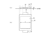
完成した非水系リチウム型蓄電素子100のたわみは、図7に示したような方法で定量化することができる。
Thereafter, the
However, the above manufacturing method shows a general example, and does not limit the manufacturing method other than that described in the claims.
The deflection of the completed nonaqueous
図7は、非水系リチウム型蓄電素子100の模式図であって、(a)は側面図、(b)は平面図である。
電極積層体1を収容しているラミネート外装体カップ部24(またはカップ形状になっている部分)の長さをx(図7(b))、非水系リチウム型蓄電素子100を平面上に水平に置いた際の電極積層体1を収容しているラミネート外装体カップ部24の端部(または、カップ形状になっている部分の端部)と平面との距離をy(図7(a))とすると、たわみ=y/xと表すことが可能である。
7A and 7B are schematic views of the non-aqueous
The length of the laminated exterior body cup portion 24 (or the cup-shaped portion) containing the electrode laminate 1 is x (FIG. 7B), and the nonaqueous
なお、x、yは同じ軸上の関係性が必要である。つまり、図7の如くxをタブ突出方向に対して垂直な方向と定めた場合は、前記yも前記x軸上でのラミネート外装体カップ部24の端部と水平面との間の距離となるようにx、yを設定する必要がある。しかしながら、x、yの位置と、例えば、外装体21から突出している負極端子用リードタブ22および正極端子用リードタブ23との位置関係は特に限定しない。
Note that x and y must have the same axial relationship. That is, when x is defined as a direction perpendicular to the tab protruding direction as shown in FIG. 7, the y is also the distance between the end of the laminate
上述の構成とすることにより、片面に金属リチウム箔6が張り付けられた両面負極5における、金属リチウムのプリドープに伴う膨潤にばらつきが生じ、たわみが生じたとしても、この両面負極5とは金属リチウム箔6の貼り付け面が逆となる両面負極5では、逆方向にたわみが生じるため、結果的に両者のたわみが相殺されることになる。したがって、電極積層体1のたわみを抑制することができ、結果的に非水系リチウム型蓄電素子100全体のたわみを抑制することができる。
By adopting the above-described configuration, even when the double-sided
なお、上記実施形態における非水系リチウム型蓄電素子100は、必要な容量や電圧を得るために、非水系リチウム型蓄電素子100を2個以上組み合わせて蓄電モジュールとして使用することができる。蓄電モジュールは、蓄電素子、モジュール外装体、および電極端子を含み、必要に応じて制御回路、安全装置、冷却装置等の付加装置を含んでいてもよい。
In addition, in order to obtain a required capacity | capacitance and voltage, the non-aqueous lithium-type
以下に、実施例、比較例を示し、本発明の特徴とするところを、さらに明確にする。
<実施例1>
市販のピッチ系活性炭(BET比表面積1955m2/g)150gをステンレススチールメッシュ製の籠に入れ、石炭系ピッチ300gを入れたステンレス製バットの上に置き、当該ステンレス製バットを電気炉(炉内有効寸法300mm×300mm×300mm)内に設置して、熱処理を行うことによって、前記ピッチ系活性炭の表面に炭素質材料を被着させた複合多孔性材料を作製した。
Hereinafter, examples and comparative examples will be shown to further clarify the features of the present invention.
<Example 1>
150 g of commercially available pitch-based activated carbon (BET specific surface area 1955 m 2 / g) is placed in a stainless steel mesh basket and placed on a stainless steel bat containing 300 g of coal-based pitch, and the stainless steel bat is placed in an electric furnace (inside the furnace) The composite porous material in which a carbonaceous material was deposited on the surface of the pitch-based activated carbon was manufactured by performing heat treatment by placing it within an effective dimension (300 mm × 300 mm × 300 mm).
熱処理は窒素雰囲気下で、670℃まで4時間で昇温し、同温度で4時間保持し、続いて自然冷却により60℃まで冷却した後、炉から取り出した。得られた複合多孔性材料はBET比表面積240m2/gであった。
上記で得た複合多孔性材料83.4質量部、アセチレンブラック8.3質量部およびPVdF(ポリフッ化ビニリデン)8.3質量部とNMP(N−メチルピロリドン)を混合して、スラリーを得た。
In the heat treatment, the temperature was raised to 670 ° C. in 4 hours in a nitrogen atmosphere, maintained at the same temperature for 4 hours, then cooled to 60 ° C. by natural cooling, and then removed from the furnace. The obtained composite porous material had a BET specific surface area of 240 m 2 / g.
83.4 parts by mass of the composite porous material obtained above, 8.3 parts by mass of acetylene black, 8.3 parts by mass of PVdF (polyvinylidene fluoride) and NMP (N-methylpyrrolidone) were mixed to obtain a slurry. .
負極集電体として用いる厚さ25μmの銅箔に、ドリルを用いて直径約1mmの孔を1cm2あたり16個になるように作成した。重量法で測定したところ、この集電体の空隙率は13%であった。
次いで、複合多孔性材料のスラリーをこの銅箔の両面に塗布し、次いで乾燥し、次いでプレスして、負極活物質層の厚さが片面あたり50μmの両面負極(以下単に「負極」という。)5を得た。
A copper foil having a thickness of 25 μm used as a negative electrode current collector was prepared using a drill so that there were 16 holes with a diameter of about 1 mm per 1 cm 2 . When measured by the gravimetric method, the porosity of the current collector was 13%.
Next, a slurry of the composite porous material is applied to both sides of the copper foil, then dried and then pressed, and the negative electrode active material layer has a thickness of 50 μm per side (hereinafter, simply referred to as “negative electrode”). 5 was obtained.
正極集電体となる15μmのアルミ箔の上に、市販のピッチ系活性炭81.6質量部、ケッチェンブラック6.1質量部およびPVdF12.3質量部とNMPを混合したものを、上記アルミ箔の片面に塗布し、次いで乾燥し、活物質層の厚さが70μmの片面正極7bを得た。さらに、反対面にも同様に厚み70μmの正極活物質層を形成した両面正極も作製した。これをプレスして、片面あたり60μmの両面正極7aを得た。 A mixture of 81.6 parts by mass of commercially available pitch-based activated carbon, 6.1 parts by mass of Ketjen Black, 12.3 parts by mass of PVdF and NMP on a 15 μm aluminum foil serving as a positive electrode current collector The single-sided positive electrode 7b having an active material layer thickness of 70 μm was obtained. Furthermore, a double-sided positive electrode having a positive electrode active material layer having a thickness of 70 μm formed on the opposite surface was also produced. This was pressed to obtain a double-sided positive electrode 7a having a thickness of 60 μm per side.
上記で得られた負極5、並びに両面正極7a、及び片面正極7bを、負極5は11.2×11.2cm2、正極7a、7bは11.0×11.0cm2に切り出した。なお、これら負極5および正極7には、それぞれ活物質層を塗布していない電極未塗工部8が含まれており、その面積は、負極5は2.5×11.2cm2、正極7は2.5×11.0cm2である。
次に、前記電極5、7を真空乾燥機で充分に乾燥させた後、21枚の負極5のそれぞれの片面の負極活物質層に8.5cm×11.0cmで厚み30μmの金属リチウム箔6を圧着した。
負極5と正極7との間にポリエチレン製のセパレータ(旭化成ケミカルズ製、厚み24μm)4を各々はさみ込み、片面正極7b、セパレータ4、負極5、セパレータ4、両面正極7a、…、セパレータ4、負極5、セパレータ4、片面正極7bの順に積層し、片面正極7b:2枚、負極5:21枚、両面正極7a:20枚が積層されてなる電極積層体1を作製した。
Next, after the
A separator made of polyethylene (manufactured by Asahi Kasei Chemicals Co., Ltd.,
この際、図2のごとく、隣接する両面負極5に圧着している金属リチウム箔6の圧着方向が互いに反対方向となるように、積層を行った。(なお、図2では負極5を8枚積層した場合を示している。)
この電極積層体1をポリプロピレンとアルミ箔の積層体からなるラミネートフィルムで形成された容器に入れ、ECとMECを1:4の体積比率で混合した非水溶媒に1mol/Lの濃度でLiN(SO2C2F5)2を溶解した非水電解液を注入して密閉し、非水系リチウム型蓄電素子100を作成した。
At this time, as shown in FIG. 2, lamination was performed so that the crimping directions of the
This electrode laminate 1 is put in a container formed of a laminate film made of a laminate of polypropylene and aluminum foil, and LiN (LiN (concentration of 1 mol / L) in a non-aqueous solvent in which EC and MEC are mixed at a volume ratio of 1: 4. A nonaqueous electrolytic solution in which SO 2 C 2 F 5 ) 2 was dissolved was injected and sealed to prepare a nonaqueous
ラミネートフィルムには、電極積層体1相当のカップ部(ラミネート外装体カップ部24)を設けており、カップ部のサイズが90mm×115mm×4mm深さであるラミネートフィルムを、電極積層体1を挟みこむ形状となるように貼り合わせたものを使用した。
作製した非水系リチウム型蓄電素子100にたわみは見られず、y/x=0.0001であり、負極活物質層に圧着した金属リチウム箔6は、60時間後にはすべて消失していた。
The laminated film is provided with a cup portion (laminated exterior body cup portion 24) corresponding to the electrode laminated body 1, and the laminated film having a cup portion size of 90 mm × 115 mm × 4 mm deep is sandwiched between the electrode laminated body 1. What was stuck together so that it might become a hollow shape was used.
Deflection was not seen in the produced non-aqueous
<実施例2>
同じく片面正極7b:2枚、負極5:21枚、両面正極7a:20枚が積層されてなる電極積層体1を作製した。
このとき、電極積層体1を構成する両面負極5のうち、上側半分の10枚の両面負極5については、図4のごとく、金属リチウム箔6を両面負極5の上面に配置し、下側半分の11枚の両面負極5については金属リチウム箔6を両面負極5の下面に配置した。金属リチウム箔6の配置位置が異なること以外は、実施例1と同様にして電極積層体1を作製し、実施例1と同様にして非水系リチウム型蓄電素子100を作製した。
作製した非水系リチウム型蓄電素子100のたわみは、y/x=0.001であった。
<Example 2>
Similarly, an electrode laminate 1 in which two single-sided positive electrodes 7b, negative electrodes 5:21, and double-sided positive electrodes 7a: 20 were laminated was produced.
At this time, among the double-sided
The deflection of the produced non-aqueous
<実施例3>
同じく片面正極7b:2枚、負極5:21枚、両面正極7a:20枚が積層されてなる電極積層体1を作製した。
このとき、電極積層体1を構成する両面負極5のうち、上側半分の10枚の両面負極5については、図5のごとく、金属リチウム箔6を両面負極5の下面に配置し、下側半分の11枚の両面負極5については金属リチウム箔6を両面負極5の上面に配置した。金属リチウム箔6の配置位置が異なること以外は、実施例1と同様にして電極積層体1を作製し、実施例1と同様にして非水系リチウム型蓄電素子100を作製した。
作製した非水系リチウム型蓄電素子100のたわみは、y/x=0.001であった。
<Example 3>
Similarly, an electrode laminate 1 in which two single-sided positive electrodes 7b, negative electrodes 5:21, and double-sided positive electrodes 7a: 20 were laminated was produced.
At this time, among the double-sided
The deflection of the produced non-aqueous
<実施例4>
同じく片面正極7b:2枚、負極5:21枚、両面正極7a:20枚が積層されてなる電極積層体1を作製した。
このとき、電極積層体1を構成する両面負極5における金属リチウム箔6の貼り付け面を、図6のごとく、上層側から2枚毎に逆となるように配置した。金属リチウム箔6の配置位置が異なること以外は、実施例1と同様にして電極積層体1を作製し、実施例1と同様にして非水系リチウム型蓄電素子100を作製した。
作製した非水系リチウム型蓄電素子100のたわみは、y/x=0.0001であった。
<Example 4>
Similarly, an electrode laminate 1 in which two single-sided positive electrodes 7b, negative electrodes 5:21, and double-sided positive electrodes 7a: 20 were laminated was produced.
At this time, the attachment surface of the
The deflection of the produced non-aqueous
<比較例1>
同じく片面正極7b:2枚、負極5:21枚、両面正極7a:20枚が積層されてなる電極積層体1を作製した。
このとき、図8のごとく、電極積層体1を構成する21枚全ての両面正極7aについて金属リチウム箔6をその下面に配置した。金属リチウム箔6の配置位置が異なること以外は、実施例1と同様にして電極積層体1を作製し、実施例1と同様にして非水系リチウム型蓄電素子100を作製した。
作製した非水系リチウム型蓄電素子100のたわみは、y/x=0.009であった。
<Comparative Example 1>
Similarly, an electrode laminate 1 in which two single-sided positive electrodes 7b, negative electrodes 5:21, and double-sided positive electrodes 7a: 20 were laminated was produced.
At this time, as shown in FIG. 8, the
The deflection of the produced nonaqueous
<実施例と比較例との対比>
実施例1から実施例4のように、負極(両面負極)5と両面正極7aとセパレータ4とを負極(両面負極)5/セパレータ4/両面正極7a/セパレータ4/負極(両面負極)5の順に積層した部分電極積層体2を1つ以上含み、且つ部分電極積層体2において、負極(両面負極)5に圧着された金属リチウム箔6の圧着方向が、セパレータ4及び両面正極7aを介して隣接する負極(両面負極)5に圧着されている金属リチウム箔6の圧着方向と面対称となるように積層した場合の、非水系リチウム型蓄電素子100のたわみは、0.001〜0.0001程度であるのに対し、負極5の下面に金属リチウム箔6が位置するように配置した比較例1の場合には、非水系リチウム型蓄電素子100のたわみは0.009であり、比較例1の方がたわみが大きいことが確認された。
<Contrast between Example and Comparative Example>
As in Example 1 to Example 4, the negative electrode (double-sided negative electrode) 5, the double-sided positive electrode 7a, and the
本発明の非水系リチウム型蓄電素子は、例えば、自動車において、内燃機関又は燃料電池、モータ、及び蓄電素子を組み合わせたハイブリット駆動システムの分野、更には瞬間電力ピークのアシスト用途等で好適に利用できる。 The non-aqueous lithium storage element of the present invention can be suitably used in, for example, the field of a hybrid drive system that combines an internal combustion engine or a fuel cell, a motor, and a storage element in an automobile, and further assists for instantaneous power peak. .
1 電極積層体
2 部分電極積層体
4 セパレータ
5 両面負極
6 金属リチウム箔
7 正極
7a 両面正極
7b 片面正極
9 負極の負極活物質層未塗工部(負極タブ)
21 外装体
22 負極端子用リードタブ
23 正極端子用リードタブ
24 ラミネート外装体カップ部
25 ラミネート外装体シール部
DESCRIPTION OF SYMBOLS 1 Electrode laminated
DESCRIPTION OF
Claims (2)
前記両面負極の一方の面にのみ、前記負極活物質層の上に金属リチウム箔を圧着する圧着工程と、
前記電極積層体において前記両面負極の上面となる面に前記金属リチウム箔が圧着された両面負極と、前記両面負極の下面となる面に前記金属リチウム箔が圧着された両面負極とを含むように、前記両面正極と前記両面負極とをセパレータを介して交互に積層する積層工程と、
前記電極積層体を外装体に収納して非水系電解液を注入する注液工程と、を含み、
前記積層工程は、前記圧着工程後の第1の両面負極と第2の両面負極とが第1の両面正極に対して面対称の位置関係となるように前記第1の両面負極/第1のセパレータ/前記第1の両面正極/第2のセパレータ/前記第2の両面負極の順に積層されてなる部分電極積層体を含んで、前記両面正極と前記圧着工程後の両面負極とを、前記セパレータを介して交互に積層して前記電極積層体とし、
且つ、前記金属リチウム箔が圧着された面が前記電極積層体における上側となるように配置された両面負極の数と、前記金属リチウム箔が圧着された面が前記電極積層体における下側となるように配置された両面負極の数との比が、2:3以上3:2以内の値となるように前記両面負極を積層することを特徴とする非水系リチウム型蓄電素子の製造方法。 A double-sided positive electrode having a positive electrode active material layer formed on both sides of the positive electrode current collector and a negative electrode active material layer containing a negative electrode active material capable of inserting and extracting lithium on both sides of the negative electrode current collector having a through hole were formed. A method of manufacturing a non-aqueous lithium storage element in which a non-aqueous electrolyte solution containing an electrode laminate in which a plurality of double-sided negative electrodes are alternately laminated via separators and a lithium ion-containing electrolyte is housed in an exterior body. And
A crimping step of crimping a metal lithium foil on the negative electrode active material layer only on one surface of the double-sided negative electrode,
In the electrode laminate, a double-sided negative electrode in which the metal lithium foil is pressure-bonded to a surface to be the upper surface of the double-sided negative electrode, and a double-sided negative electrode in which the metal lithium foil is pressure-bonded to a surface to be the lower surface of the double-sided negative electrode A lamination step of alternately laminating the double-sided positive electrode and the double-sided negative electrode via a separator;
See containing and a liquid injection step of injecting a non-aqueous electrolyte solution by accommodating the electrode stack to the exterior body,
In the laminating step, the first double-sided negative electrode / the first double-sided negative electrode / the first double-sided negative electrode and the second double-sided negative electrode after the crimping step are in a plane-symmetrical positional relationship with respect to the first double-sided positive electrode. Including a partial electrode laminate that is laminated in the order of separator / first double-sided positive electrode / second separator / second double-sided negative electrode, wherein the double-sided positive electrode and the double-sided negative electrode after the crimping step are separated from the separator The electrode laminate is laminated alternately through
And the number of double-sided negative electrodes arranged so that the surface to which the metal lithium foil is crimped is the upper side of the electrode laminate, and the surface to which the metal lithium foil is crimped is the lower side of the electrode laminate The double-sided negative electrode is laminated so that the ratio to the number of double-sided negative electrodes arranged in such a manner is a value of 2: 3 or more and 3: 2 or less .
前記両面負極の一方の面にのみ、前記負極活物質層の上に金属リチウム箔を圧着する圧着工程と、
前記電極積層体において前記両面負極の上面となる面に前記金属リチウム箔が圧着された両面負極と、前記両面負極の下面となる面に前記金属リチウム箔が圧着された両面負極とを含むように、前記両面正極と前記両面負極とをセパレータを介して交互に積層する積層工程と、
前記電極積層体を外装体に収納して非水系電解液を注入する注液工程と、を含み、
前記積層工程は、前記圧着工程後の第1の両面負極と第2の両面負極とが第1の両面正極に対して面対称の位置関係となり且つ前記第2の両面負極と前記圧着工程後の第3の両面負極とが、第2の両面正極に対して面対称の位置関係となるように、前記第1の両面負極/第1のセパレータ/前記第1の両面正極/第2のセパレータ/前記第2の両面負極/第3のセパレータ/前記第2の両面正極/第4のセパレータ/前記第3の両面負極の順に積層されてなる、前記第2の両面負極を共有する2組の部分電極積層体を含んで、前記両面正極と前記圧着工程後の両面負極とを、前記セパレータを介して交互に積層して前記電極積層体とし、
且つ、前記金属リチウム箔が圧着された面が前記電極積層体における上側となるように配置された両面負極の数と、前記金属リチウム箔が圧着された面が前記電極積層体における下側となるように配置された両面負極の数との比が、2:3以上3:2以内の値となるように前記両面負極を積層することを特徴とする非水系リチウム型蓄電素子の製造方法。 A double-sided positive electrode having a positive electrode active material layer formed on both sides of the positive electrode current collector and a negative electrode active material layer containing a negative electrode active material capable of inserting and extracting lithium on both sides of the negative electrode current collector having a through hole were formed. A method of manufacturing a non-aqueous lithium storage element in which a non-aqueous electrolyte solution containing an electrode laminate in which a plurality of double-sided negative electrodes are alternately laminated via separators and a lithium ion-containing electrolyte is housed in an exterior body. And
A crimping step of crimping a metal lithium foil on the negative electrode active material layer only on one surface of the double-sided negative electrode,
In the electrode laminate, a double-sided negative electrode in which the metal lithium foil is pressure-bonded to a surface to be the upper surface of the double-sided negative electrode, and a double-sided negative electrode in which the metal lithium foil is pressure-bonded to a surface to be the lower surface of the double-sided negative electrode A lamination step of alternately laminating the double-sided positive electrode and the double-sided negative electrode via a separator;
See containing and a liquid injection step of injecting a non-aqueous electrolyte solution by accommodating the electrode stack to the exterior body,
In the laminating step, the first double-sided negative electrode and the second double-sided negative electrode after the crimping step are in a plane-symmetrical positional relationship with respect to the first double-sided positive electrode and the second double-sided negative electrode and the post-crimping step The first double-sided negative electrode / first separator / the first double-sided positive electrode / second separator / so that the third double-sided negative electrode has a plane-symmetrical positional relationship with respect to the second double-sided positive electrode Two sets of portions sharing the second double-sided negative electrode, which are laminated in the order of the second double-sided negative electrode / third separator / the second double-sided positive electrode / fourth separator / the third double-sided negative electrode Including the electrode laminate, the double-sided positive electrode and the double-sided negative electrode after the crimping step are alternately laminated via the separator to form the electrode laminate,
And the number of double-sided negative electrodes arranged so that the surface to which the metal lithium foil is crimped is the upper side of the electrode laminate, and the surface to which the metal lithium foil is crimped is the lower side of the electrode laminate The double-sided negative electrode is laminated so that the ratio to the number of double-sided negative electrodes arranged in such a manner is a value of 2: 3 or more and 3: 2 or less .
Priority Applications (1)
| Application Number | Priority Date | Filing Date | Title |
|---|---|---|---|
| JP2011225742A JP5855893B2 (en) | 2011-10-13 | 2011-10-13 | Method for producing non-aqueous lithium storage element |
Applications Claiming Priority (1)
| Application Number | Priority Date | Filing Date | Title |
|---|---|---|---|
| JP2011225742A JP5855893B2 (en) | 2011-10-13 | 2011-10-13 | Method for producing non-aqueous lithium storage element |
Publications (2)
| Publication Number | Publication Date |
|---|---|
| JP2013089625A JP2013089625A (en) | 2013-05-13 |
| JP5855893B2 true JP5855893B2 (en) | 2016-02-09 |
Family
ID=48533281
Family Applications (1)
| Application Number | Title | Priority Date | Filing Date |
|---|---|---|---|
| JP2011225742A Expired - Fee Related JP5855893B2 (en) | 2011-10-13 | 2011-10-13 | Method for producing non-aqueous lithium storage element |
Country Status (1)
| Country | Link |
|---|---|
| JP (1) | JP5855893B2 (en) |
Families Citing this family (8)
| Publication number | Priority date | Publication date | Assignee | Title |
|---|---|---|---|---|
| US10002718B2 (en) | 2013-11-29 | 2018-06-19 | Asahi Kasei Kabushiki Kaisha | Lithium ion capacitor |
| JP2016096250A (en) * | 2014-11-14 | 2016-05-26 | 旭化成株式会社 | Lithium ion capacitor |
| JP6871676B2 (en) * | 2015-11-26 | 2021-05-12 | 株式会社ジェイテクト | Power storage device and manufacturing method of power storage device |
| JP6405394B2 (en) * | 2017-01-24 | 2018-10-17 | 太陽誘電株式会社 | Electrochemical devices |
| JP6837868B2 (en) * | 2017-02-27 | 2021-03-03 | 太陽誘電株式会社 | Electrochemical device |
| JP6837898B2 (en) * | 2017-04-07 | 2021-03-03 | 太陽誘電株式会社 | Electrochemical device |
| JP7000791B2 (en) * | 2017-10-17 | 2022-01-19 | 株式会社豊田自動織機 | Lithium-ion secondary battery manufacturing method and short-circuit inspection method |
| KR20200067434A (en) * | 2018-12-04 | 2020-06-12 | 주식회사 엘지화학 | Method for preparing negative electrode of lithium secondary battery |
Family Cites Families (6)
| Publication number | Priority date | Publication date | Assignee | Title |
|---|---|---|---|---|
| CN101138058B (en) * | 2005-03-31 | 2011-03-30 | 富士重工业株式会社 | Lithium ion capacitor |
| JP4738042B2 (en) * | 2005-03-31 | 2011-08-03 | 旭化成株式会社 | Non-aqueous lithium storage element and method for manufacturing the same |
| JP2008300692A (en) * | 2007-05-31 | 2008-12-11 | Fuji Heavy Ind Ltd | Power storage device |
| JP2008305648A (en) * | 2007-06-06 | 2008-12-18 | Fdk Corp | Nonaqueous power storage device |
| JP2011082038A (en) * | 2009-10-07 | 2011-04-21 | Sumitomo Electric Ind Ltd | Power generation element for nonaqueous electrolyte battery, method of manufacturing the same, and nonaqueous electrolyte battery using the same |
| JP5474596B2 (en) * | 2010-02-15 | 2014-04-16 | 富士重工業株式会社 | Power storage device |
-
2011
- 2011-10-13 JP JP2011225742A patent/JP5855893B2/en not_active Expired - Fee Related
Also Published As
| Publication number | Publication date |
|---|---|
| JP2013089625A (en) | 2013-05-13 |
Similar Documents
| Publication | Publication Date | Title |
|---|---|---|
| JP4738042B2 (en) | Non-aqueous lithium storage element and method for manufacturing the same | |
| US10297885B2 (en) | Lithium ion battery and capacitor hybrid system in a single pouch | |
| JP5855893B2 (en) | Method for producing non-aqueous lithium storage element | |
| JP7461877B2 (en) | Compositions and methods for multilayer electrode films | |
| JP3705801B1 (en) | Lithium ion secondary battery | |
| US10211440B2 (en) | Nonaqueous electrolyte secondary battery | |
| JP5096851B2 (en) | Method for manufacturing power storage device | |
| JP2014232666A (en) | Nonaqueous electrolyte secondary battery | |
| JP2020537309A (en) | Lithium metal secondary battery and battery module containing it | |
| JP5420852B2 (en) | Lithium ion battery electrode | |
| JP5214172B2 (en) | Electrode manufacturing method and storage device manufacturing method | |
| US20150263334A1 (en) | Non-aqueous electrolyte secondary battery | |
| JP6062668B2 (en) | Secondary battery and secondary battery module | |
| WO2013047379A1 (en) | Lithium secondary battery and method for producing same | |
| JP2007087801A (en) | Lithium ion secondary battery | |
| JP2013197052A (en) | Lithium ion power storage device | |
| JP5840429B2 (en) | Lithium ion capacitor | |
| JP2012028366A (en) | Power storage device | |
| JP2009009858A (en) | Electrode for lithium ion secondary battery | |
| JP2014212304A (en) | Power storage device and method of manufacturing power storage module | |
| JP5637199B2 (en) | Electrode for lithium ion secondary battery | |
| JP2016181457A (en) | Flat plate type laminate battery and battery pack thereof | |
| US11769899B2 (en) | Press jig and method of manufacturing secondary battery using same | |
| CN114583244B (en) | Lithium ion secondary battery | |
| JP2011216685A (en) | Composite electricity storage device |
Legal Events
| Date | Code | Title | Description |
|---|---|---|---|
| A621 | Written request for application examination |
Free format text: JAPANESE INTERMEDIATE CODE: A621 Effective date: 20141009 |
|
| A977 | Report on retrieval |
Free format text: JAPANESE INTERMEDIATE CODE: A971007 Effective date: 20150604 |
|
| A131 | Notification of reasons for refusal |
Free format text: JAPANESE INTERMEDIATE CODE: A131 Effective date: 20150630 |
|
| A521 | Written amendment |
Free format text: JAPANESE INTERMEDIATE CODE: A523 Effective date: 20150828 |
|
| TRDD | Decision of grant or rejection written | ||
| A01 | Written decision to grant a patent or to grant a registration (utility model) |
Free format text: JAPANESE INTERMEDIATE CODE: A01 Effective date: 20151201 |
|
| A61 | First payment of annual fees (during grant procedure) |
Free format text: JAPANESE INTERMEDIATE CODE: A61 Effective date: 20151210 |
|
| R150 | Certificate of patent or registration of utility model |
Ref document number: 5855893 Country of ref document: JP Free format text: JAPANESE INTERMEDIATE CODE: R150 |
|
| LAPS | Cancellation because of no payment of annual fees |