JP5854861B2 - Imaging device, control method thereof, and control program - Google Patents
Imaging device, control method thereof, and control program Download PDFInfo
- Publication number
- JP5854861B2 JP5854861B2 JP2012015295A JP2012015295A JP5854861B2 JP 5854861 B2 JP5854861 B2 JP 5854861B2 JP 2012015295 A JP2012015295 A JP 2012015295A JP 2012015295 A JP2012015295 A JP 2012015295A JP 5854861 B2 JP5854861 B2 JP 5854861B2
- Authority
- JP
- Japan
- Prior art keywords
- state
- subject
- eye
- eyes
- image data
- Prior art date
- Legal status (The legal status is an assumption and is not a legal conclusion. Google has not performed a legal analysis and makes no representation as to the accuracy of the status listed.)
- Expired - Fee Related
Links
Images

Description
本発明は、被写体の動きに応じて自動的に撮影を実行する撮像装置、その制御方法、および制御プログラムに関する。 The present invention relates to an imaging apparatus that automatically performs imaging in accordance with the movement of a subject, a control method thereof, and a control program.
デジタルカメラなどの撮像装置において、被写体である被撮影者(ユーザ)が所望の画像を撮影するため、被写体に所定の動きが検出されると静止画撮影を実行するようにしたものが知られている。 In an imaging apparatus such as a digital camera, it is known that a subject (user) who is a subject shoots a desired image, so that a predetermined motion is detected in the subject and still image shooting is performed. Yes.
例えば、撮像素子で撮像された動画像に基づいて、被写体の両目の画像を連続的に検出し、当該検出結果に応じて所定の動きであるウインクを検出するようにしたものがある。ここでは、ウインクが検出されると、静止画像を撮影するためシャッタが切られる(特許文献1参照)。 For example, there is one in which images of both eyes of a subject are continuously detected based on a moving image captured by an image sensor, and a wink that is a predetermined movement is detected according to the detection result. Here, when a wink is detected, the shutter is released to capture a still image (see Patent Document 1).
加えて、所定の動きの検出をトリガとする静止画撮影の他にも、例えば、画像処理によってウインクなどの所定の動き検出し、当該検出結果に応じて様々なシステムを遠隔操作するようにしたものもある。 In addition to still image shooting triggered by detection of a predetermined motion, for example, a predetermined motion such as a wink is detected by image processing, and various systems are remotely operated according to the detection result. There are also things.
ところで、特許文献1においては、被撮影者である被写体の撮影を遠隔操作で行う際、被撮影者の所望のタイミングで静止画の撮影を行うため、ウインクを検出すると当該ウインクを行った被撮影者の撮影を実行するようにしている。 By the way, in Japanese Patent Application Laid-Open No. 2004-133620, when a subject that is a subject is photographed remotely, a still image is photographed at a timing desired by the subject. The person's photography is executed.
このため、所定の動きであるウインクができず、例えば、ウインクをしようとして両目を瞑ってしまった場合には、ウインクと判定されない(例えば、目瞑りだと判定する)。従って、ウインクを行うことが困難であるか又はできない人(被撮影者)であると、ウインクという目の動作で撮像装置に指示を与えることができない。ここで、ウインクのように片目を瞑るだけではなく、両目を瞑った場合も撮像装置に指示を与える構成とすることが考えられるが、このような構成にしてしまうと、瞬きの度に撮像装置に指示を与えることになってしまうという別の問題が生じてしまう。 For this reason, a wink that is a predetermined movement cannot be performed. For example, if both eyes are meditated to wink, it is not determined to be a wink (for example, it is determined that the eyes are meditated). Therefore, if the person who is difficult or unable to wink (a person to be photographed), an instruction cannot be given to the imaging apparatus by the action of an eye called wink. Here, it is conceivable that the imaging apparatus is configured not only to meditate one eye as in the case of wink but also to medicate both eyes. Another problem arises that would be to give instructions.
よって、本発明の目的はウインクが苦手な人でも目の開閉動作によって撮影の指示を行うことのできる撮像装置、その制御方法、および制御プログラムを提供することにある。 Therefore, an object of the present invention is to provide an imaging apparatus, a control method therefor, and a control program that can give a shooting instruction by opening and closing an eye even for a person who is not good at winking.
上記の目的を達成するため、本発明による撮像装置は、被写体を撮像して画像データを記録する撮像装置であって、撮影待機状態で順次読み出される複数の画像データに基づいて、前記被写体が一方の目を瞑ったこと、および前記被写体が両方の目を瞑ったことを判定する判定手段と、前記被写体が第1の状態もしくは第2の状態である場合に、前記被写体を撮影する撮影手段とを有し、前記第1の状態は、前記被写体が一方の目を瞑った状態が所定の第1の判定時間以上継続する状態であり、前記第2の状態は、前記被写体が両方の目を瞑った状態が前記第1の判定時間よりも長い第2の判定時間以上継続する状態であることを特徴とする。 In order to achieve the above object, an imaging apparatus according to the present invention is an imaging apparatus that captures an image of a subject and records image data, and the subject is one based on a plurality of image data sequentially read in a shooting standby state. Determination means for determining that the subject has meditated , and that the subject has closed both eyes, and imaging means for photographing the subject when the subject is in the first state or the second state; The first state is a state in which the subject is in a state where one eye is meditated for a predetermined first determination time or longer, and the second state is a state in which the subject is in both eyes. The meditated state is a state of continuing for a second determination time longer than the first determination time .
本発明による制御方法は、被写体を撮像して画像データを記録する撮像装置の制御方法であって、撮影待機状態で順次読み出される複数の画像データに基づいて、前記被写体が一方の目を瞑ったこと、および前記被写体が両方の目を瞑ったことを判定する判定ステップと、前記被写体が第1の状態もしくは第2の状態である場合に、前記被写体を撮影する撮影ステップとを有し、前記第1の状態は、前記被写体が一方の目を瞑った状態が所定の第1の判定時間以上継続する状態であり、前記第2の状態は、前記被写体が両方の目を瞑った状態が前記第1の判定時間よりも長い第2の判定時間以上継続する状態であることを特徴とする。 A control method according to the present invention is a control method for an imaging apparatus that captures an image of a subject and records the image data, and the subject relaxes one eye based on a plurality of image data sequentially read in a shooting standby state . And a determination step of determining that the subject has meditated on both eyes, and a photographing step of photographing the subject when the subject is in the first state or the second state, The first state is a state in which the subject is meditated on one eye for a predetermined first determination time or longer, and the second state is a state in which the subject is meditated on both eyes. It is the state which continues more than 2nd determination time longer than 1st determination time, It is characterized by the above-mentioned.
本発明による制御プログラムは、被写体を撮像して画像データを記録する撮像装置で用いられる制御プログラムであって、前記撮像装置が備えるコンピュータに、撮影待機状態で順次読み出される複数の画像データに基づいて、前記被写体が一方の目を瞑ったこと、および前記被写体が両方の目を瞑ったことを判定する判定ステップと、前記被写体が第1の状態もしくは第2の状態である場合に、前記被写体を撮影する撮影ステップとを実行させるものであり、前記第1の状態は、前記被写体が一方の目を瞑った状態が所定の第1の判定時間以上継続する状態であり、前記第2の状態は、前記被写体が両方の目を瞑った状態が前記第1の判定時間よりも長い第2の判定時間以上継続する状態であることを特徴とする。 A control program according to the present invention is a control program used in an imaging apparatus that images a subject and records image data, and is based on a plurality of image data sequentially read out in a shooting standby state by a computer included in the imaging apparatus. A step of determining that the subject has meditated one eye and the subject has meditated both eyes; and when the subject is in the first state or the second state, The first state is a state in which the subject is in a state where one eye is meditated for a predetermined first determination time or longer, and the second state is The state where the subject is in a state where both eyes are meditated is a state in which the subject continues for a second determination time longer than the first determination time .
本発明によれば、ウインクなどの所定の動きが苦手な人でも、両目を瞑った状態においても所定の判定条件を満たせば、所望のタイミングで撮影を行うことができる。 According to the present invention, even a person who is not good at a predetermined movement, such as wink, can take a picture at a desired timing if the predetermined determination condition is satisfied even in a state where both eyes are meditated.
以下、本発明の実施の形態による撮像装置について図面を参照して説明する。 Hereinafter, an imaging device according to an embodiment of the present invention will be described with reference to the drawings.
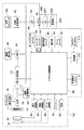
図1は、本発明による撮像装置の一例であるデジタルカメラの構成を示すブロック図である。 FIG. 1 is a block diagram showing a configuration of a digital camera which is an example of an imaging apparatus according to the present invention.
図1において、デジタルカメラ100は撮影レンズ10および絞り機能を備える機械式シャッタ12を有している。被写体などの光学像が撮影レンズ10およびシャッタ12を介して撮像素子14に結像する。撮像素子14はこの光学像に応じた電気信号(アナログ信号)を出力する。このアナログ信号はA/D変換器16によってデジタル信号(画像データ)に変換される。
In FIG. 1, a
撮像素子14およびA/D変換器16にはタイミング発生回路18からクロック信号および制御信号が供給され、撮像素子14およびA/D変換器16はクロック信号および制御信号に応じて動作する。タイミング発生回路18はシステム制御回路50の制御下で動作するメモリ制御回路22によって制御される。
A clock signal and a control signal are supplied from the timing generation circuit 18 to the
タイミング発生回路18によって、撮像素子14のリセットタイミングを制御すれば、撮像素子14の電荷蓄積時間を制御することができる。つまり、タイミング発生回路18によるリセットタイミング制御によって所謂電子シャッタが実現される。
If the reset timing of the
画像処理回路20はA/D変換器16から供給される画像データ又はメモリ制御回路22から与えられる画像データに対して所定の画素補間処理および色変換処理を行う。画像処理回路20は画像データから画像の切り出しおよび変倍処理を行って電子ズーム機能を行う。
The
さらに、画像処理回路20は、撮像の結果得られた画像データに応じて所定の演算処理を行う。そして、システム制御回路50は当該演算結果に基づいて露光制御部40および測距制御部42を制御する。これによって、露光制御部40および測距制御部42は、所謂TTL(through the lens)方式によるAF(自動焦点)処理、AE(自動露出)処理、およびEF処理を行う。
Further, the
加えて、画像処理回路20は、撮像の結果得られた画像データに応じて所定の演算処理を行って得られた演算結果に基づいてTTL方式のAWB(オートホワイトバランス)処理を行う。
In addition, the
メモリ制御回路22はA/D変換器16、タイミング発生回路18、画像処理回路20、メモリ30、および圧縮・伸長回路32を制御する。A/D変換器16から出力された画像データは画像処理回路20およびメモリ制御回路22を介して又は直接メモリ制御回路22を介してメモリ30に書き込まれる。
The memory control circuit 22 controls the A /
画像表示部28は、例えば、TFT LCDで構成され、メモリ30に書き込まれた画像データはメモリ制御回路22によって画像として画像表示部28に表示される。そして、画像表示部28に画像を逐次表示するようにすれば、電子ファインダー機能として用いることができる。
The
さらに、画像表示部28はシステム制御回路50の制御によってその表示がオン又はオフされる。表示をオフすれば、撮像装置100における電力消費を大幅に低減することができる。
Further, the display of the
メモリ30には、前述のように、撮影の結果得られた画像データが格納される(この画像データには静止画像データおよび動画像データが含まれる)。このメモリ30は所定枚数の静止画像データおよび所定時間の動画像データを格納するために十分な記憶容量を有している。
As described above, the image data obtained as a result of shooting is stored in the memory 30 (this image data includes still image data and moving image data). The
この結果、複数枚の静止画像を連続して撮影する所謂連写撮影又はパノラマ撮影の際においても、高速かつ大量の画像データをメモリ30に書き込むことができる。なお、メモリ30はシステム制御回路50の作業領域としても用いることが可能である。
As a result, a large amount of image data can be written in the
不揮発性メモリ31は、例えば、Flash ROMであり、システム制御回路50が実行するプログラムコードが不揮発性メモリ31に格納されている。そして、システム制御回路50は不揮発性メモリ50からプログラムコードを逐次読み出して実行する。
The
なお、不揮発性メモリ31にはシステム情報を記憶する領域およびユーザ設定情報を記憶する領域が設定され、種々の情報および設定を次回起動の際に、システム制御回路50が読み出す。
The
圧縮・伸長回路32は適応離散コサイン変換(ADCT)などによって画像データを圧縮伸長する。例えば、圧縮・伸長回路32はメモリ30に格納された画像データを読み込んで圧縮処理又は伸長処理を行って、処理済みの画像データをメモリ30に書き込む。
The compression /
露光制御部40は絞り機能を備えるシャッタ12を制御する。また、露光制御部40はフラッシュ48と連動するフラッシュ調光機能も有している。
The
測距制御部42は撮影レンズ10のフォーカシングを制御する。ズーム制御部44は撮影レンズ10のズーミングを制御する。フラッシュ48はAF補助光の投光機能およびフラッシュ調光機能を有している。
The distance
前述のように、露光制御部40および測距制御部42はTTL方式によって制御され、画像処理回路20による演算結果に基づいて、システム制御回路50が露光制御部40および測距制御部42を制御する。
As described above, the
図示のように、システム制御回路50には、モードダイアルスイッチ60、シャッタスイッチ62および64、表示切替スイッチ66、操作部70、およびズームスイッチ72が接続されている。
As shown in the figure, a
モードダイアルスイッチ60は、電源のオフ、自動撮影モード、撮影モード、パノラマ撮影モード、動画撮影モード、およびHDR(ダイナミックレンジ拡張撮影)動画撮影モードなどの機能モードを切り替え設定する際に用いられる。
The
シャッタスイッチ62は、シャッタボタン(図示せず)の操作途中でオンとなって、第1のシャッタスイッチ信号SW1をシステム制御回路50に送出する。これによって、システム制御回路50はAF(オートフォーカス)処理、AE(自動露出)処理、およびAWB(オートホワイトバランス)処理などの動作開始を指示する。
The
シャッタスイッチ64はシャッタボタンの操作完了でオンとなって、第2のシャッタスイッチ信号SW2をシステム制御回路50に送る。これによって、システム制御回路50は、例えば、フラッシュ撮影の場合には、EF(フラッシュプリ発光)処理を行った後、AE処理で決定された露光時間だけ撮像素子14を露光させる。
The
フラッシュ撮影の場合には、露光時間中にフラッシュ48の発光が行われて、露光時間が終了すると、露光制御部40はシステム制御回路50の制御下でシャッタ12を制御して遮光を行って、撮像素子14に対する露光を終了させる。
In the case of flash photography, the
前述のように、撮像素子14から読み出されたアナログ信号はA/D変換器16およびメモリ制御回路22を介してメモリ30に画像データとして書き込まれる(読み出し処理)。そして、画像処理回路20およびメモリ制御回路22における演算結果を用いた現像処理とメモリ30から画像データを読み出して圧縮・伸長回路32で圧縮を行う圧縮処理とがシステム制御回路50の制御下で行われる。そして、圧縮後の画像データは後述する記録媒体200に書き込まれる(記録処理)。
As described above, the analog signal read from the
表示切替スイッチ66の操作によって、システム制御回路50の制御下で画像表示部28の表示切替が行われる。この表示切替によって光学ファインダー104を用いて撮影を行う際、前述のように画像表示部28に対する電源供給が遮断されて省電力を図ることができる。
By the operation of the
操作部70は、例えば、各種のボタン、タッチパネル、および回転式ダイアルを備えている。図示はしないが、各種のボタンには、メニューボタン、セットボタン、マクロボタン、マルチ画面再生改ページボタン、フラッシュ設定ボタン、および単写/連写/セルフタイマー切り替えボタンなどがある。
The
ズームスイッチ72はユーザによって操作され、ズームスイッチ72の操作によって、システム制御回路50は撮像画像の倍率変更指示を行う。このズームスイッチ72は、撮像画角を望遠側に変更させるテレスイッチと、広角側に変更させるワイドスイッチとを有している。
The
ズームスイッチ72の操作によって、ズーム制御部44はシステム制御回路50の制御下で撮影レンズ10の撮像画角を変更して光学ズームを実行する。また、ズームスイッチ72の操作によって、画像処理回路20による画像の切り出しおよび画素補間処理などの撮像画角の電子的なズーミング変更が行われる。
By operating the
電源86は、例えば、アルカリ電池などの一次電池、又はNiCd電池、NiMH電池、又はLiイオン電池等の二次電池を備えるとともに、ACアダプターを有している。
The
インタフェース(I/F)90はメモリカード又はハードディスク等の記録媒体200とデジタルカメラ100とのインタフェースであり、I/F90はコネクタ92によって記録媒体200と接続される。
An interface (I / F) 90 is an interface between the
記録媒体200は半導体メモリ又は磁気ディスクなどの記録部202およびインタフェース(I/F)204を備えており、記録媒体200はコネクタ206によってデジタルカメラ100に接続される。
The
通信部110は、例えば、USB、IEEE1394の機能、およびLAN機能、無線通信機能などを備えている。そして、通信部110はコネクタ112によって外部機器(図示せず)に接続される。なお、無線通信機能を用いる場合には、コネクタ112にはアンテナが接続される。
The
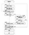
図2は、図1に示すデジタルカメラ100における撮影動作を説明するためのフローチャートである。ここでは、ウインクを検出することで、静止画撮影を行う処理を例に挙げて説明を行う。
FIG. 2 is a flowchart for explaining a photographing operation in the
ここでは、デジタルカメラ100は撮影待機状態にあり、この撮影待機状態においては、撮像素子14から、例えば、60fpsなど静止画撮影の際の読み出し処理に比べて高速で複数の画像信号(アナログ信号)が順次読み出される。画像信号はA/D変換器16でA/D変換されて、前述のように画像処理回路20において画像変換又は変倍処理が行われる。
Here, the
その後、メモリ制御回路22はメモリ30に画像データを書き込む。さらに、前述用に、メモリ30に書き込まれた画像データは画像表示部28に表示される。このようにして、画像表示部28に表示される画像データはスルー画像データと呼ばれる。そして、撮影待機状態においては、撮像素子14の読み出し処理から画像の表示までが繰り返し行われる。
Thereafter, the memory control circuit 22 writes the image data into the
上述の撮影待機状態において、システム制御回路50は顔検出および主顔判定を行う(ステップS201)。ここで、主顔判定とは、例えば、複数の顔が検出された際に第1優先の人物を判定して特定する処理をいう。顔検出においては、システム制御回路50はメモリ30に書き込まれた画像データに対して、周知の顔検出処理を用いて、画像データが示す画像の人物領域において顔領域を検出する。
In the above-described shooting standby state, the
周知の顔検出手法としては、例えば、ニューラルネットワークを用いた手法、および目、鼻、および口など形状に特徴のある部位を画像から検索して、テンプレートマッチングを用いて類似度が所定の閾値以上であれば顔とみなす手法などがある。さらに、顔検出手法として、両目間の距離および顔の輪郭などの画像特徴量を検出して、統計的解析を用いた手法なども知られている。そして、顔検出精度を高めるためには、これらの手法を組み合わせて検出処理を行うことが望ましい。なお、特開2002−251380号公報には、ウェーブレット変換および画像特徴量を用いて顔検出する手法が記載されている。 Known face detection methods include, for example, a method using a neural network, and a part having a characteristic shape such as an eye, nose, and mouth is searched from an image, and the similarity is equal to or higher than a predetermined threshold using template matching. If so, there is a method to consider it as a face. Further, as a face detection method, a method using statistical analysis by detecting image feature amounts such as a distance between both eyes and a face outline is also known. In order to improve face detection accuracy, it is desirable to perform detection processing by combining these methods. Japanese Patent Laid-Open No. 2002-251380 describes a method for detecting a face using wavelet transform and image feature amounts.
主顔判定では、検出された顔の大きさおよび当該顔の画面中心からの距離、そして、予め登録された顔と当該検出された顔が同一人物であるか否かなど各項目の判定結果に応じて、各項目に対して重み付けを行う。そして、当該重み付けに応じて第1優先の顔を主顔として決定する。 In the main face determination, the size of the detected face, the distance from the screen center of the face, and the determination result of each item such as whether or not the pre-registered face and the detected face are the same person are used. Accordingly, each item is weighted. Then, the first priority face is determined as the main face according to the weighting.
例えば、画像上の各顔に対して、顔のサイズが大きいほど、そして、顔の位置が画面の中心に近いほど重み係数(評価値)を大きくして、最も評価値の高い顔を主顔として判定する。さらには、予め不揮発性メモリ31などに人物の優先順位を優先順位データとして格納し、システム制御回路50が優先順位データに応じて主顔を判定するようにしてもよい。
For example, for each face on the image, the larger the face size and the closer the face position is to the center of the screen, the larger the weighting coefficient (evaluation value) is, and the face with the highest evaluation value is the main face. Judge as. Further, the priority order of the person may be stored in advance in the
なお、人物を特定する際には、予め不揮発性メモリ31などに登録された人物画像の目、鼻、および口など形状に特徴のある部位に対してテンプレートマッチングが行われる。
When specifying a person, template matching is performed on a part having a characteristic shape such as eyes, nose and mouth of a person image registered in advance in the
続いて、システム制御回路50は主顔について左右の目の各々について目瞑り状態であるか否かの目瞑り判定を行う(ステップS202)。目瞑り判定においては、システム制御回路50は、まず、目瞑りを判定するための領域を決定する。ここでは、顔検出の際に得られた目の中心を基準として、システム制御回路50は顔の大きさに応じて判定対象とする領域(目領域)の大きさを求める。
Subsequently, the
図3は、図1に示すシステム制御回路50で行われる目領域の決定を説明するための図である。
FIG. 3 is a diagram for explaining the eye area determination performed by the
図3において、点線で示す枠301は顔検出によって検出された顔(顔領域ともいう)を特定する枠である。当該枠301において、二重丸302の中心が顔領域における左目の中心を示す。そして、システム制御回路50は左目の中心を基準として枠301の大きさに応じて、点線で示す目領域303(左目領域)を決定する。同様にして、システム制御回路50は、右目の中心を基準として、枠301の大きさに応じて右目領域を決定する。システム制御回路50は左目領域および右目領域の各々を目を瞑っているか否かを判定する判定領域とする。
In FIG. 3, a
さらに、目瞑りの判定では、左目領域および右目領域の各々についてその瞳領域を抽出し特定する(瞳領域判定)。瞳領域の抽出については、顔検出と同様に、ニューラルネットワークなどを用いた手法又はテンプレートマッチングなどが用いられる。あるいは、瞳と推定される色あるいは輝度を有する領域を瞳領域として抽出するようにしてもよい。 Further, in the determination of eye meditation, the pupil region is extracted and specified for each of the left eye region and the right eye region (pupil region determination). For the extraction of the pupil region, a method using a neural network or template matching or the like is used as in face detection. Alternatively, an area having a color or luminance estimated as a pupil may be extracted as a pupil area.
瞳領域(つまり、左瞳領域および右瞳領域)を判定した後、システム制御回路50は判定対象領域(つまり、左目領域および右目領域)の面積に対する瞳領域の面積の割合を求める(以下、瞳領域割合と呼ぶ)。なお、左目領域の面積に対する左瞳領域の面積の割合を第1の割合とし、右目領域の面積に対する右瞳領域の面積の割合を第2の割合とする。
After determining the pupil region (that is, the left pupil region and the right pupil region), the
続いて、システム制御回路50は予め設定された目瞑りスレッシュレベルと(第1のスレッシュレベル)瞳領域割合とを比較して、瞳領域割合が目瞑りスレッシュレベル未満であるか否かを判定する(瞳領域割合判定)。この瞳領域割合判定は左目領域および右目領域の各々について行われる。
Subsequently, the
瞳領域割合が目瞑りスレッシュレベル未満(第1のスレッシュレベル未満)であると、システム制御回路50は当該目(左目又は右目)は瞑った状態であると判定する。一方、瞳領域割合が目瞑りスレッシュレベル以上(第1のスレッシュレベル以上)であると、システム制御回路50は、当該目(左目又は右目)は開いた状態であると判定する。
If the pupil area ratio is less than the eye meditation threshold level (less than the first threshold level), the
次に、システム制御回路50は両目とも瞑った状態であるか否かを判定する(ステップS203)。ここでは、左目および右目がともに瞑った状態であれば、システム制御回路50は両目が瞑った状態であるとする。
Next, the
両目とも開いていると(ステップS203において、YES)、システム制御回路50はステップS201の処理に戻る。
If both eyes are open (YES in step S203),
一方、両目とも開いた状態でないと(ステップS203において、NO)、システム制御回路50は両目ともに瞑った状態であるか否かを判定する(ステップS204)。
On the other hand, if both eyes are not open (NO in step S203), the
左目又は右目が開いた状態であると、つまり、左目および右目のいずれか一方が瞑った状態であると(ステップS204において、NO)、システム制御回路50は予め規定された判定時間Ta(第1の判定時間)を設定する(ステップS205)。
If the left eye or the right eye is in an open state, that is, if either the left eye or the right eye is in a relaxed state (NO in step S204), the
続いて、システム制御回路50は、瞑っていたと判定した目が判定時間Ta以上瞑られていたか否かを判定する(ステップS206)。つまり、システム制御回路50は、一方の目を瞑った状態が所定の第1の判定時間以上継続する第1の状態であるかを判定することになる。
Subsequently, the
ステップS206における判定の際には、システム制御回路50はフレーム毎に目瞑り判定を行って、判定時間Taに対応するフレーム分目瞑り状態であれば、判定時間Ta以上に亘って目瞑り状態であったとする。
At the time of the determination in step S206, the
目瞑り状態が判定時間Ta未満であると(ステップS206において、NO)、システム制御回路50はステップS201の処理に戻る。一方、目瞑り状態が判定時間Ta以上であると(ステップS206において、YES)、システム制御回路50は静止画撮影を実行する(ステップS207)。
If the eye-meditation state is less than determination time Ta (NO in step S206),
ステップS207の静止画撮影においては、システム制御回路50はメモリ制御回路22を介してタイミング発生回路18を制御して、撮像素子14から静止画を読み出す。そして、読み出した静止画(アナログ信号)はA/D変換器16でA/D変換処理された後、画像処理回路20において画像変換が行われる。
In still image shooting in step S207, the
その後、画像データは圧縮・伸長回路32において画像圧縮が施されて、メモリ制御回路22を介して圧縮データがメモリ30に一旦記憶される。そして、システム制御回路50の制御下で、メモリ制御回路22はメモリ30に記憶された圧縮データを読み出して、記録媒体200に記憶する。
Thereafter, the image data is subjected to image compression in the compression /
両目ともに瞑った状態であると(ステップS204において、YES)、システム制御回路50は、前述の目瞑りスレッシュレベルを両目用スレッシュレベル(第2のスレッシュレベル)に設定する(ステップS208)。この両目用スレッシュレベルは目瞑りスレッシュレベルよりも低い。つまり、システム制御回路50は目瞑りを判定する際の基準を厳しくすることになる。これによって、システム制御回路50は完全な目瞑り状態ではない場合、例えば、瞬きなどの場合について、目瞑り状態と判定しにくいようにする。
If both eyes are in a meditated state (YES in step S204), the
続いて、システム制御回路50は左右両目について、瞳領域割合と両目用スレッシュレベルとを比較して、瞳領域割合が両目用スレッシュレベル未満(第2のスレッシュレベル未満)であるか否かを判定する(ステップS209)。
Subsequently, the
両目の瞳領域割合が両目用スレッシュレベル以上であると(ステップS209において、NO)、つまり、目瞑り状態であると判定しないと、システム制御回路50はステップS201の処理に戻る。
If the pupil area ratio of both eyes is greater than or equal to the threshold level for both eyes (NO in step S209), that is, if it is not determined that the eyes are in a closed state, the
瞳領域割合が両目用スレッシュレベル未満であると(ステップS209において、YES)、つまり、目瞑り状態であると確認すると、システム制御回路50は判定時間Tb(第2の判定時間)を設定する(ステップS210)。この判定時間Tbは上記の判定時間Taよりも長い時間である。
If the pupil area ratio is less than the threshold level for both eyes (YES in step S209), that is, if it is confirmed that the eyes are in a closed state, the
続いて、システム制御回路50はステップS206の処理に移行して、瞑っていたと判定した目(つまり、両目)が判定時間Tb以上瞑られていたか否かを判定することになる。つまり、システム制御回路50は、両方の目を瞑った状態が第2の判定時間以上継続する第2の状態であるか否かを判定することになる。
Subsequently, the
このように、本発明の実施の形態では、片目が目瞑り状態であると判定するための判定基準を、両目が目瞑り状態であると判定するための判定基準よりも緩く設定する。これによって、ウインク検出の検出を容易に行うことができる。 As described above, in the embodiment of the present invention, the determination criterion for determining that one eye is in an eye-mealing state is set to be looser than the determination criterion for determining that both eyes are in an eye-mealing state. Thereby, it is possible to easily detect the wink detection.
目にゴミが入るなどの特別な事情を除いては、通常の生活で片目だけを瞑ることは少ないため、片目が目瞑りであると判定するための判定基準を緩くしても誤判定が増えることほとんどない。 Except for special circumstances such as entering the eyes, it is rare to meditate only one eye in normal life, so even if you loosen the criteria for judging that one eye is meditation, misjudgments increase There is almost nothing.
さらに、上述のように、片目が目瞑り状態であるとの誤判定は少ないので、判定時間Taは判定時間Tbよりも短くする。これによって、撮影開始までの時間を短くすることができる。 Further, as described above, since there are few erroneous determinations that one eye is in a closed state, the determination time Ta is made shorter than the determination time Tb. As a result, the time until the start of photographing can be shortened.
一方、両目が目瞑り状態であると判定する際には、通常の瞬きと明確に区別するため、判定時間Tbは判定時間Taに比べて長く設定される。望ましくは、判定時間Tbは通常の瞬きの動作に要する時間よりも十分に長く設定する。 On the other hand, when it is determined that both eyes are in a closed state, the determination time Tb is set longer than the determination time Ta in order to clearly distinguish it from normal blinking. Desirably, the determination time Tb is set sufficiently longer than the time required for the normal blinking operation.
以上のように、本発明の実施の形態では、両目を瞑った場合でも所定の判定基準を用いて撮影開始の合図としてのトリガとして用いることができ、この結果、ウインクができない又は困難な人でも目の合図によって撮影を開始することができる。その結果、ウインクできない又は困難な人でも所望のタイミングで静止画の撮影を行うことができる。 As described above, in the embodiment of the present invention, even when both eyes are meditated, it can be used as a trigger as a cue to start shooting using a predetermined determination criterion. As a result, even a person who cannot wink or is difficult to wink Shooting can be started by an eye signal. As a result, even a person who cannot wink or has difficulty can take a still image at a desired timing.
なお、上述の実施の形態では、主顔判定にされた人物に対して目瞑り検出を行うようにしたが、予め登録された特定の人物を検出して当該人物に対して目瞑り検出を行うようにしてもよい。 In the above-described embodiment, eye meditation detection is performed on a person who is determined to be the main face, but a specific person registered in advance is detected and eye meditation detection is performed on the person. You may do it.
さらに、瞳領域割合に基づいて目瞑り判定を行うようにしたが、目瞑りの度合いを示す指標であれば他の指標を用いるようにしてもよい。 Further, although the eye meditation determination is performed based on the pupil area ratio, other indices may be used as long as the indices indicate the degree of eye meditation.
また、両目ともに瞑った状態であれば、システム制御回路50は、ステップS208において目瞑りスレッシュレベルを両目用スレッシュレベルに設定したが、この処理は必ずしも必要ではなく、省略しても構わない。
Further, if both eyes are in a state of being meditated, the
上述の説明から明らかなように、図1に示す例では、システム制御回路50が判定手段として機能し、システム制御回路50、メモリ制御回路22、画像処理回路20、タイミング発生回路18、A/D変換器16、および撮像素子14などが撮影手段として機能する。そして、システム制御回路50は、目領域決定手段、瞳領域抽出手段、割合算出手段として機能する。
As is clear from the above description, in the example shown in FIG. 1, the
以上、本発明について実施の形態に基づいて説明したが、本発明は、これらの実施の形態に限定されるものではなく、この発明の要旨を逸脱しない範囲の様々な形態も本発明に含まれる。 As mentioned above, although this invention was demonstrated based on embodiment, this invention is not limited to these embodiment, Various forms of the range which does not deviate from the summary of this invention are also contained in this invention. .
例えば、上記の実施の形態の機能を制御方法として、この制御方法を撮像装置に実行させるようにすればよい。また、上述の実施の形態の機能を有するプログラムを制御プログラムとして、この制御プログラムを撮像装置が備えるコンピュータに実行させるようにしてもよい。なお、制御プログラムは、例えば、コンピュータに読み取り可能な記録媒体に記録される。 For example, the function of the above embodiment may be used as a control method, and this control method may be executed by the imaging apparatus. Further, a program having the functions of the above-described embodiments may be used as a control program, and the control program may be executed by a computer included in the imaging apparatus. The control program is recorded on a computer-readable recording medium, for example.
また、本発明は、以下の処理を実行することによっても実現される。即ち、上述した実施形態の機能を実現するソフトウェア(プログラム)を、ネットワーク又は各種記録媒体を介してシステム或いは装置に供給し、そのシステム或いは装置のコンピュータ(またはCPUやMPU等)がプログラムを読み出して実行する処理である。 The present invention can also be realized by executing the following processing. That is, software (program) for realizing the functions of the above-described embodiments is supplied to a system or apparatus via a network or various recording media, and a computer (or CPU, MPU, etc.) of the system or apparatus reads the program. It is a process to be executed.
11 撮影レンズ
14 撮像素子
18 タイミング発生回路
20 画像処理回路
22 メモリ制御回路
28 画像表示部
30 メモリ
50 システム制御回路
62,64 シャッタスイッチ
200 記録媒体
DESCRIPTION OF SYMBOLS 11
Claims (5)
撮影待機状態で順次読み出される複数の画像データに基づいて、前記被写体が一方の目を瞑ったこと、および前記被写体が両方の目を瞑ったことを判定する判定手段と、
前記被写体が第1の状態もしくは第2の状態である場合に、前記被写体を撮影する撮影手段とを有し、
前記第1の状態は、前記被写体が一方の目を瞑った状態が所定の第1の判定時間以上継続する状態であり、前記第2の状態は、前記被写体が両方の目を瞑った状態が前記第1の判定時間よりも長い第2の判定時間以上継続する状態であることを特徴とする撮像装置。 An imaging device that images a subject and records image data,
Based on the plurality of image data are sequentially read in a photographing standby state, determination means for determining that said that the subject Shut one eye, and wherein the subject is Shut both eyes,
Photographing means for photographing the subject when the subject is in the first state or the second state;
The first state is a state in which the subject is meditated on one eye for a predetermined first determination time or longer, and the second state is a state in which the subject is meditated on both eyes. An imaging apparatus characterized by being in a state of continuing for a second determination time longer than the first determination time .
前記複数の画像データから前記被写体の左目および右目をそれぞれ規定する左目領域および右目領域を決定する目領域決定手段と、
前記左目領域および前記右目領域から前記被写体の左右の瞳を示す左瞳領域および右瞳領域を抽出する瞳領域抽出手段と、
前記左目領域の面積に対する前記左瞳領域の面積の割合を第1の割合として求めるとともに、前記右目領域の面積に対する前記右瞳領域の面積の割合を第2の割合として求める割合算出手段とを有し、
前記第1の割合および前記第2の割合の各々が予め定められた第1のスレッシュレベル未満であるか否かを判定して、前記第1の割合が前記第1のスレッシュレベル未満であると、前記左目を瞑った状態であると判定し、前記第2の割合が前記第1のスレッシュレベル未満であると前記右目を瞑った状態であると判定することを特徴とする請求項1に記載の撮像装置。 The determination means includes
Eye region determining means for determining a left eye region and a right eye region that respectively define a left eye and a right eye of the subject from the plurality of image data ;
Pupil region extraction means for extracting a left pupil region and a right pupil region indicating left and right pupils of the subject from the left eye region and the right eye region;
Together determine the ratio of the area of the left pupil region to an area of the eye region as a first percentage of, organic and ratio calculating means for calculating a ratio of the area of the right pupil region to the area of the right-eye region as a second percentage of And
It is determined whether each of the first ratio and the second ratio is less than a predetermined first threshold level, and the first ratio is less than the first threshold level. , determines that the state with shut the left, according to claim 1, wherein the second percentage of, wherein the determining that the state with shut the right eye is less than the first threshold level Imaging device.
撮影待機状態で順次読み出される複数の画像データに基づいて、前記被写体が一方の目を瞑ったこと、および前記被写体が両方の目を瞑ったことを判定する判定ステップと、
前記被写体が第1の状態もしくは第2の状態である場合に、前記被写体を撮影する撮影ステップとを有し、
前記第1の状態は、前記被写体が一方の目を瞑った状態が所定の第1の判定時間以上継続する状態であり、前記第2の状態は、前記被写体が両方の目を瞑った状態が前記第1の判定時間よりも長い第2の判定時間以上継続する状態であることを特徴とする制御方法。 A method of controlling an imaging apparatus that images a subject and records image data,
Based on the plurality of image data are sequentially read in a photographing standby state, a determination step that said subject is Shut one eye, and wherein the subject is Shut both eyes,
A photographing step of photographing the subject when the subject is in the first state or the second state;
The first state is a state in which the subject is meditated on one eye for a predetermined first determination time or longer, and the second state is a state in which the subject is meditated on both eyes. A control method characterized by being in a state of continuing for a second determination time longer than the first determination time .
前記撮像装置が備えるコンピュータに、
撮影待機状態で順次読み出される複数の画像データに基づいて、前記被写体が一方の目を瞑ったこと、および前記被写体が両方の目を瞑ったことを判定する判定ステップと、
前記被写体が第1の状態もしくは第2の状態である場合に、前記被写体を撮影する撮影ステップとを実行させるものであり、
前記第1の状態は、前記被写体が一方の目を瞑った状態が所定の第1の判定時間以上継続する状態であり、前記第2の状態は、前記被写体が両方の目を瞑った状態が前記第1の判定時間よりも長い第2の判定時間以上継続する状態であることを特徴とする制御プログラム。 A control program used in an imaging device that images a subject and records image data,
In the computer provided in the imaging device,
Based on the plurality of image data are sequentially read in a photographing standby state, a determination step that said subject is Shut one eye, and wherein the subject is Shut both eyes,
A photographing step of photographing the subject when the subject is in the first state or the second state;
The first state is a state in which the subject is meditated on one eye for a predetermined first determination time or longer, and the second state is a state in which the subject is meditated on both eyes. A control program characterized by being in a state of continuing for a second determination time longer than the first determination time .
Priority Applications (1)
| Application Number | Priority Date | Filing Date | Title |
|---|---|---|---|
| JP2012015295A JP5854861B2 (en) | 2012-01-27 | 2012-01-27 | Imaging device, control method thereof, and control program |
Applications Claiming Priority (1)
| Application Number | Priority Date | Filing Date | Title |
|---|---|---|---|
| JP2012015295A JP5854861B2 (en) | 2012-01-27 | 2012-01-27 | Imaging device, control method thereof, and control program |
Publications (3)
| Publication Number | Publication Date |
|---|---|
| JP2013157716A JP2013157716A (en) | 2013-08-15 |
| JP2013157716A5 JP2013157716A5 (en) | 2015-03-12 |
| JP5854861B2 true JP5854861B2 (en) | 2016-02-09 |
Family
ID=49052546
Family Applications (1)
| Application Number | Title | Priority Date | Filing Date |
|---|---|---|---|
| JP2012015295A Expired - Fee Related JP5854861B2 (en) | 2012-01-27 | 2012-01-27 | Imaging device, control method thereof, and control program |
Country Status (1)
| Country | Link |
|---|---|
| JP (1) | JP5854861B2 (en) |
Cited By (1)
| Publication number | Priority date | Publication date | Assignee | Title |
|---|---|---|---|---|
| EP3363346A3 (en) * | 2017-01-27 | 2018-11-28 | Carl Zeiss Vision International GmbH | Computer-implemented method for detecting a cornea vertex |
Families Citing this family (1)
| Publication number | Priority date | Publication date | Assignee | Title |
|---|---|---|---|---|
| US9549118B2 (en) * | 2014-03-10 | 2017-01-17 | Qualcomm Incorporated | Blink and averted gaze avoidance in photographic images |
Family Cites Families (1)
| Publication number | Priority date | Publication date | Assignee | Title |
|---|---|---|---|---|
| JP5109864B2 (en) * | 2008-08-08 | 2012-12-26 | 株式会社ニコン | Electronic still camera |
-
2012
- 2012-01-27 JP JP2012015295A patent/JP5854861B2/en not_active Expired - Fee Related
Cited By (2)
| Publication number | Priority date | Publication date | Assignee | Title |
|---|---|---|---|---|
| EP3363346A3 (en) * | 2017-01-27 | 2018-11-28 | Carl Zeiss Vision International GmbH | Computer-implemented method for detecting a cornea vertex |
| US10441168B2 (en) | 2017-01-27 | 2019-10-15 | Carl Zeiss Vision International Gmbh | Computer-implemented method for detecting a corneal vertex |
Also Published As
| Publication number | Publication date |
|---|---|
| JP2013157716A (en) | 2013-08-15 |
Similar Documents
| Publication | Publication Date | Title |
|---|---|---|
| US9667888B2 (en) | Image capturing apparatus and control method thereof | |
| JP5424732B2 (en) | Imaging apparatus, control method thereof, and program | |
| JP5258531B2 (en) | Imaging apparatus and zoom control method | |
| JP2009044682A (en) | Imaging apparatus and control method thereof | |
| JP6148431B2 (en) | Imaging apparatus and control method thereof | |
| JP5889247B2 (en) | Image processing apparatus, image processing method, image processing program, and imaging apparatus | |
| JP2007081732A (en) | Imaging apparatus | |
| JP2017126915A (en) | Imaging apparatus | |
| JP5854861B2 (en) | Imaging device, control method thereof, and control program | |
| JP2011013683A (en) | Imaging apparatus, auto focus method, and program for allowing computer to perform the method | |
| JP2016019161A (en) | Imaging device | |
| JP4891163B2 (en) | Image processing apparatus, image processing method, and image processing program | |
| JP2010041629A (en) | Imaging device and controlling method and program | |
| JP6289068B2 (en) | Imaging apparatus and control method thereof | |
| JP2008011264A (en) | Imaging apparatus, its control method, program, and storage medium | |
| JP2015034895A (en) | Imaging device and control method for the same | |
| JP2010041399A (en) | Imaging device and its control method | |
| JP2012199986A (en) | Imaging apparatus and control method thereof | |
| JP2008060844A (en) | Image processor and image processing method | |
| JP5828722B2 (en) | Imaging apparatus, control method therefor, program, and storage medium | |
| JP2011013682A (en) | Imaging apparatus, auto focus method, and program for allowing computer to perform the method | |
| JP2010092066A (en) | Imaging apparatus, automatic focusing method, and program for allowing computer to perform the method | |
| JP6526270B2 (en) | Image pickup apparatus and control method thereof | |
| JP2015171113A (en) | Image processing system and control method of the same | |
| JP2016167088A (en) | Imaging device and control method of the same |
Legal Events
| Date | Code | Title | Description |
|---|---|---|---|
| A521 | Request for written amendment filed |
Free format text: JAPANESE INTERMEDIATE CODE: A523 Effective date: 20150126 |
|
| A621 | Written request for application examination |
Free format text: JAPANESE INTERMEDIATE CODE: A621 Effective date: 20150126 |
|
| A977 | Report on retrieval |
Free format text: JAPANESE INTERMEDIATE CODE: A971007 Effective date: 20151019 |
|
| TRDD | Decision of grant or rejection written | ||
| A01 | Written decision to grant a patent or to grant a registration (utility model) |
Free format text: JAPANESE INTERMEDIATE CODE: A01 Effective date: 20151110 |
|
| A61 | First payment of annual fees (during grant procedure) |
Free format text: JAPANESE INTERMEDIATE CODE: A61 Effective date: 20151208 |
|
| R151 | Written notification of patent or utility model registration |
Ref document number: 5854861 Country of ref document: JP Free format text: JAPANESE INTERMEDIATE CODE: R151 |
|
| LAPS | Cancellation because of no payment of annual fees |