JP5849055B2 - Access device - Google Patents
Access device Download PDFInfo
- Publication number
- JP5849055B2 JP5849055B2 JP2012553149A JP2012553149A JP5849055B2 JP 5849055 B2 JP5849055 B2 JP 5849055B2 JP 2012553149 A JP2012553149 A JP 2012553149A JP 2012553149 A JP2012553149 A JP 2012553149A JP 5849055 B2 JP5849055 B2 JP 5849055B2
- Authority
- JP
- Japan
- Prior art keywords
- access device
- mounting portion
- ladder member
- access
- ladder
- Prior art date
- Legal status (The legal status is an assumption and is not a legal conclusion. Google has not performed a legal analysis and makes no representation as to the accuracy of the status listed.)
- Active
Links
- 238000005065 mining Methods 0.000 claims description 6
- 230000008602 contraction Effects 0.000 description 2
- 238000010586 diagram Methods 0.000 description 2
- 230000004048 modification Effects 0.000 description 2
- 238000012986 modification Methods 0.000 description 2
- 230000009286 beneficial effect Effects 0.000 description 1
Images


Classifications
-
- E—FIXED CONSTRUCTIONS
- E06—DOORS, WINDOWS, SHUTTERS, OR ROLLER BLINDS IN GENERAL; LADDERS
- E06C—LADDERS
- E06C7/00—Component parts, supporting parts, or accessories
- E06C7/18—Devices for preventing persons from falling
- E06C7/181—Additional gripping devices, e.g. handrails
- E06C7/183—Additional gripping devices, e.g. handrails situated along the ladder
-
- B—PERFORMING OPERATIONS; TRANSPORTING
- B60—VEHICLES IN GENERAL
- B60R—VEHICLES, VEHICLE FITTINGS, OR VEHICLE PARTS, NOT OTHERWISE PROVIDED FOR
- B60R3/00—Arrangements of steps or ladders facilitating access to or on the vehicle, e.g. running-boards
- B60R3/02—Retractable steps or ladders, e.g. movable under shock
-
- B—PERFORMING OPERATIONS; TRANSPORTING
- B63—SHIPS OR OTHER WATERBORNE VESSELS; RELATED EQUIPMENT
- B63B—SHIPS OR OTHER WATERBORNE VESSELS; EQUIPMENT FOR SHIPPING
- B63B27/00—Arrangement of ship-based loading or unloading equipment for cargo or passengers
- B63B27/14—Arrangement of ship-based loading or unloading equipment for cargo or passengers of ramps, gangways or outboard ladders ; Pilot lifts
-
- E—FIXED CONSTRUCTIONS
- E02—HYDRAULIC ENGINEERING; FOUNDATIONS; SOIL SHIFTING
- E02F—DREDGING; SOIL-SHIFTING
- E02F9/00—Component parts of dredgers or soil-shifting machines, not restricted to one of the kinds covered by groups E02F3/00 - E02F7/00
- E02F9/08—Superstructures; Supports for superstructures
- E02F9/0833—Improving access, e.g. for maintenance, steps for improving driver's access, handrails
-
- E—FIXED CONSTRUCTIONS
- E06—DOORS, WINDOWS, SHUTTERS, OR ROLLER BLINDS IN GENERAL; LADDERS
- E06C—LADDERS
- E06C1/00—Ladders in general
- E06C1/02—Ladders in general with rigid longitudinal member or members
- E06C1/38—Special constructions of ladders, e.g. ladders with more or less than two longitudinal members, ladders with movable rungs or other treads, longitudinally-foldable ladders
- E06C1/39—Ladders having platforms; Ladders changeable into platforms
- E06C1/393—Ladders having platforms foldable with the ladder
-
- E—FIXED CONSTRUCTIONS
- E06—DOORS, WINDOWS, SHUTTERS, OR ROLLER BLINDS IN GENERAL; LADDERS
- E06C—LADDERS
- E06C5/00—Ladders characterised by being mounted on undercarriages or vehicles Securing ladders on vehicles
- E06C5/02—Ladders characterised by being mounted on undercarriages or vehicles Securing ladders on vehicles with rigid longitudinal members
- E06C5/04—Ladders characterised by being mounted on undercarriages or vehicles Securing ladders on vehicles with rigid longitudinal members capable of being elevated or extended ; Fastening means during transport, e.g. mechanical, hydraulic
- E06C5/06—Ladders characterised by being mounted on undercarriages or vehicles Securing ladders on vehicles with rigid longitudinal members capable of being elevated or extended ; Fastening means during transport, e.g. mechanical, hydraulic by piston and cylinder, or equivalent means, operated by a pressure medium
-
- E—FIXED CONSTRUCTIONS
- E06—DOORS, WINDOWS, SHUTTERS, OR ROLLER BLINDS IN GENERAL; LADDERS
- E06C—LADDERS
- E06C9/00—Ladders characterised by being permanently attached to fixed structures, e.g. fire escapes
- E06C9/06—Ladders characterised by being permanently attached to fixed structures, e.g. fire escapes movably mounted
- E06C9/08—Ladders characterised by being permanently attached to fixed structures, e.g. fire escapes movably mounted with rigid longitudinal members
-
- B—PERFORMING OPERATIONS; TRANSPORTING
- B60—VEHICLES IN GENERAL
- B60R—VEHICLES, VEHICLE FITTINGS, OR VEHICLE PARTS, NOT OTHERWISE PROVIDED FOR
- B60R3/00—Arrangements of steps or ladders facilitating access to or on the vehicle, e.g. running-boards
- B60R3/005—Catwalks, running boards for vehicle tops, access means for vehicle tops; Handrails therefor
-
- E—FIXED CONSTRUCTIONS
- E04—BUILDING
- E04F—FINISHING WORK ON BUILDINGS, e.g. STAIRS, FLOORS
- E04F11/00—Stairways, ramps, or like structures; Balustrades; Handrails
- E04F11/02—Stairways; Layouts thereof
- E04F11/04—Movable stairways, e.g. of loft ladders which may or may not be concealable or extensible
- E04F11/06—Movable stairways, e.g. of loft ladders which may or may not be concealable or extensible collapsible, e.g. folding, telescopic
-
- E—FIXED CONSTRUCTIONS
- E06—DOORS, WINDOWS, SHUTTERS, OR ROLLER BLINDS IN GENERAL; LADDERS
- E06C—LADDERS
- E06C7/00—Component parts, supporting parts, or accessories
- E06C7/18—Devices for preventing persons from falling
- E06C7/181—Additional gripping devices, e.g. handrails
Landscapes
- Engineering & Computer Science (AREA)
- Mechanical Engineering (AREA)
- Mining & Mineral Resources (AREA)
- Civil Engineering (AREA)
- General Engineering & Computer Science (AREA)
- Structural Engineering (AREA)
- Chemical & Material Sciences (AREA)
- Combustion & Propulsion (AREA)
- Ocean & Marine Engineering (AREA)
- Ladders (AREA)
- Vehicle Step Arrangements And Article Storage (AREA)
- Portable Nailing Machines And Staplers (AREA)
- Adjustment Of The Magnetic Head Position Track Following On Tapes (AREA)
Description
本発明はアクセス装置に関し、具体的には、基部面と高所面との間のアクセスを提供し、アクセス位置と保管位置との間で移動可能である、アクセス装置に関する。
本装置は一対のはしご部材を有する。アクセス位置において、はしご部材は高所面から一般的に外方かつ下方に伸長する。保管位置において、はしご部材は装着部に近接して略垂直に配置されるように格納され、はしご部材の1つは第1のはしご部材に対して略反転される。
The present invention relates to an access device, and more particularly to an access device that provides access between a base surface and an elevation surface and is movable between an access position and a storage position.
The apparatus has a pair of ladder members. In the access position, the ladder member extends generally outward and downward from the elevation surface. In the storage position, the ladder member is stored so as to be disposed substantially vertically adjacent to the mounting portion, and one of the ladder members is substantially inverted with respect to the first ladder member.
本発明のアクセス装置は、鉱山車両、土工車両または鉄道車両などの車両の高所昇降口上に搭載するのに特に有益である。 The access device of the present invention is particularly useful for mounting on an elevation lift of a vehicle such as a mining vehicle, earthwork vehicle, or railway vehicle.
本明細書における任意の従来の刊行物(もしくは刊行物から派生する情報)または既知である任意の事項に対する参照は、従来の刊行物(もしくは刊行物から派生する情報)または既知の事項が、本明細書が関連する技術分野において共通の一般知識の一部を形成するということを承認、許可またはいかなる形式においても示唆するものと理解されず、また理解されてはならない。 References to any conventional publication (or information derived from a publication) or any known matter in this specification are intended to refer to any previous publication (or information derived from the publication) or known matter. It should not be understood, nor should it be understood, as an admission, permission or suggestion in any form that the specification forms part of the common general knowledge in the relevant technical field.
基部面と、鉱山車両、土工車両または鉄道車両などの車両上の高所面との間のアクセスのためのアクセス装置を提供する場合は、アクセス装置の収容位置においては、アクセス装置が車両の通常の操作を妨害せず、アクセス装置のアクセス位置においては、基部面と高所面との間のアクセスを容易にするようにアクセス装置を設置する必要がある。 When providing an access device for access between a base surface and a high surface on a vehicle such as a mining vehicle, earthwork vehicle or railway vehicle, the access device is normally In the access position of the access device, it is necessary to install the access device so as to facilitate access between the base surface and the high surface.
車両によっては、アクセス装置が車両の先端部から外方に伸長することが車両の通常の操作を妨害することもあるため、アクセス装置が車両の先端部から外側にまったく伸長しないことが望ましいこともある。このような状況では、アクセス装置を車両の高所面の上面に設置することがより好ましい。 Depending on the vehicle, it may be desirable that the access device does not extend outward from the front end of the vehicle at all because it may interfere with normal operation of the vehicle if the access device extends outward from the front end of the vehicle. is there. In such a situation, it is more preferable to install the access device on the upper surface of the high place of the vehicle.
アクセス位置において、好ましくは、装置は所定の角度の範囲内に配置されることが求められ、角度の範囲は一般的には、60°から75°の間であり、最適にはおそらく62°である。これにより、ユーザが使用しやすくなり、労働安全衛生要件に適合する。装置はまた、ユーザが装置を昇降しやすいように手すりを設けることが好ましい。 In the access position, preferably the device is required to be located within a predetermined angular range, which is typically between 60 ° and 75 °, optimally at 62 °. is there. This makes it easier for the user to use and meets occupational health and safety requirements. The device is also preferably provided with a handrail so that the user can easily raise and lower the device.
本発明は、基部面と高所面との間のアクセスを提供するためのアクセス装置を提供することを目的とする。 It is an object of the present invention to provide an access device for providing access between a base surface and an elevation surface.
本発明はまた、アクセス位置と保管位置との間を移動可能なアクセス装置を提供することを目的とする。アクセス位置において、アクセス装置は、略整列して、高所面から角度を付けて外方かつ下方に伸長する第1のはしご部材および第2のはしご部材を有する。保管位置において、第1のはしご部材および第2のはしご部材のそれぞれは、高所面の装着部の略上面の位置へ格納される。 It is another object of the present invention to provide an access device that can move between an access position and a storage position. In the access position, the access device has a first ladder member and a second ladder member that are generally aligned and extend outwardly and downwardly at an angle from a high surface. In the storage position, each of the first ladder member and the second ladder member is stored at a position substantially on the upper surface of the mounting portion on the high surface.
広範な一形態において、本発明は、基部面と高所面との間のアクセスを提供するように構成されるアクセス装置を提供する。本アクセス装置は、
該装置を高所面の略上面に固定するための装着部と、
第1のはしご部材であって、その第1の端部が装着部に枢着される第1のはしご部材と、
第2のはしご部材であって、その第1の端部が第1のはしご部材の第2の端部に、関節点で枢着される第2のはしご部材と、
装着部と第1のはしご部材との間に動作可能に接続され、アクセス位置と保管位置との間における第1のはしご部材の動作を制御する駆動手段と、
装着部と関節点との間に動作可能に接続され、駆動手段が第1のはしご部材を移動させるときに、第2のはしご部材の移動を案内する少なくとも1つのガイドアームと、を備え、
ユーザによる駆動手段の操作によって、アクセス位置と保管位置との間におけるアクセス装置の動作を制御し、
アクセス位置において、第1のはしご部材および第2のはしご部材のそれぞれは略整列し、高所面から略外方かつ下方に伸長し、
保管位置において、第1のはしご部材および第2のはしご部材のそれぞれは装着部の略上面に略垂直に配置されるように格納される。
In one broad form, the present invention provides an access device configured to provide access between a base surface and an elevation surface. This access device
A mounting portion for fixing the device to a substantially upper surface of a high place;
A first ladder member, the first ladder member having a first end pivotally attached to the mounting portion;
A second ladder member, the first ladder member having a first end pivotally connected to a second end of the first ladder member at an articulation point;
Drive means operatively connected between the mounting portion and the first ladder member for controlling the operation of the first ladder member between the access position and the storage position;
At least one guide arm operatively connected between the mounting portion and the joint point and guiding the movement of the second ladder member when the drive means moves the first ladder member;
The operation of the access device between the access position and the storage position is controlled by the operation of the driving means by the user,
In the access position, each of the first ladder member and the second ladder member is substantially aligned and extends generally outward and downward from the elevation surface;
In the storage position, each of the first ladder member and the second ladder member is stored so as to be disposed substantially vertically on the substantially upper surface of the mounting portion.
好ましくは、駆動手段は、
三角形の配列で離間する3つの枢動コネクタを有する回転可能な部材と、
装着部に枢着される、前記コネクタのうちの第1のコネクタと、
第1のはしご部材に制御アームを介して枢着される、前記コネクタのうちの第2のコネクタと、
装着部の先端部に伸長可能なアームを介して枢着される、コネクタのうちの第3のコネクタと、を含み、
伸長可能なアームの収縮または伸長が生じることによって、該回転可能な部材が第1のコネクタを中心として回転し、結果として、アクセス装置がアクセス位置と保管位置との間を移動する。
Preferably, the driving means is
A rotatable member having three pivot connectors spaced apart in a triangular array;
A first connector of the connectors pivotally attached to a mounting portion;
A second of the connectors pivotally attached to a first ladder member via a control arm;
A third connector of the connectors pivotally attached to the distal end portion of the mounting portion via an extendable arm,
The contraction or extension of the extensible arm causes the rotatable member to rotate about the first connector, resulting in the access device moving between the access position and the storage position.
また好ましくは、アクセス装置はガイドアームに取り付けられた手すりをさらに含む。
好ましくは、駆動手段は油圧、空気圧または電動シリンダを含む。
また好ましくは、装置は鉱山車両、土工車両、鉄道車両または類似の車両に取り付けられる。
Also preferably, the access device further includes a handrail attached to the guide arm.
Preferably, the drive means includes a hydraulic, pneumatic or electric cylinder.
Also preferably, the device is attached to a mining vehicle, earthwork vehicle, railway vehicle or similar vehicle.
また好ましくは、アクセス位置において、はしご部材はそれぞれ、基部面に対して60°から75°の間に配置され、最も好ましくは62°に配置される。
本発明は、本発明の好ましい、ただし限定するものではない実施形態を、添付図と関連して記載する以下の詳細な説明によって、より完全に理解されよう。
Also preferably, in the access position, the ladder members are each arranged between 60 ° and 75 ° with respect to the base surface, most preferably at 62 °.
The present invention will be more fully understood from the following detailed description, taken in conjunction with the accompanying drawings, of preferred but non-limiting embodiments of the invention.
複数の図を通じて、別段の明示がない限り、類似の符号は類似する特徴を特定するために用いられる。
本アクセス装置は概して符号1で表され、基部面2と高所面3との間のアクセスを提供する。装置1は装着部4と、第1のはしご部材5と、第2のはしご部材6と、駆動手段7と、ガイドアーム8とを含む。
Throughout the figures, similar symbols are used to identify similar features unless otherwise indicated.
The access device is generally designated 1 and provides access between the
装着部4はアクセス装置1を高所面3(図示せず)上に固定するためのものである。高所面は鉱山車両、土工車両、鉄道車両またはその他車両などの車両の昇降口であってよい。
The
第1のはしご部材5の第1の端部9(図2参照)は枢着点(pivotal connection)10で、装着部4に枢着される。第1のはしご部材5の第2の端部11は枢着点13で、第2のはしご部材6の第1の端部12に枢着される。駆動手段7は装着部4と第1のはしご部材5との間で動作可能に接続される。駆動手段7は以下に説明するように、図7で示すアクセス位置と、図9で示す保管位置との間の、第1のはしご部材5の動作を制御する。図8は図7のアクセス位置と図9の保管位置との中間である、装置の中間位置を例示する。
The first end 9 (see FIG. 2) of the
図示する一対のガイドアーム8は装着部4と第2のはしご部材6との間に動作可能に接続される。図示するガイドアーム8は、枢支点16で装着部4と枢着される第1のガイドアーム部材14(図1参照)と、第2のガイドアーム部材15とを有する。第2のガイドアーム部材15は、枢支点(pivot point)17で第1のガイドアーム部材14と枢着され、枢支点または関節点18で第2のはしご部材6と枢着される。関節点18は、第1のはしご部材5と第2のはしご部材6との間の関節点である。
A pair of guide arms 8 shown in the figure is operatively connected between the mounting
したがって、ユーザが駆動手段7を操作すると、第1のはしご部材5が移動する。この移動が起こると、ガイド部材14,15を含むガイドアーム8は、アクセス位置と保管位置との間で第2のはしご部材6の動作を制御または案内する。
Therefore, when the user operates the driving means 7, the
図4および図7に例示するように、アクセス位置においては、第1のはしご部材5および第2のはしご部材6のそれぞれは略整列し、高所面3から角度を付けて外方かつ下方に伸長する。
As illustrated in FIGS. 4 and 7, in the access position, each of the
ユーザが駆動手段7を起動すると、図5に矢印19で示すように、図5および図8に示す中間位置を介して、図6に示す保管位置まで装置が移動する。
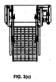
図6および図9に示す保管位置では、第1のはしご部材5および第2のはしご部材6のそれぞれが格納される。格納位置では、はしご部材5,6は、装着部4の上面に略垂直に配置されるように設置される。この位置では、はしご部材5,6はお互いに対して、アクセス位置から略180°枢動している。
When the user activates the driving means 7, the apparatus moves to the storage position shown in FIG. 6 through the intermediate position shown in FIGS. 5 and 8, as indicated by an
In the storage position shown in FIGS. 6 and 9, the
図7(b)、図8(b)および図9(b)は、アクセス位置、中間位置、格納位置における駆動手段7を示す詳細図である。
駆動手段7は、3つの枢着点21,22,23を有する回転可能な部材20を含む。第1の枢着点21は装着部4に取り付けられる。第2の枢着点22は枢着点25において、第1のはしご部材5に制御アーム24によって取り付けられる。
FIGS. 7B, 8B, and 9B are detailed views showing the driving means 7 at the access position, the intermediate position, and the storage position.
The drive means 7 includes a
第3の枢着点23は装着部4に、伸長可能なアーム機構26を介して取り付けられる。したがって、伸長可能なアーム機構26の収縮または伸長によって、回転可能な部材20が枢支点21を中心として回転する。第1のはしご部材5は回転可能な部材20に接続しているため、回転可能な部材20が枢支点21を中心として回転することによって、第1のはしご部材5の動作を制御する。
The
その結果、伸長可能なアーム26が伸長または収縮すると、図8に示す中間位置を介して、図7に示すアクセス位置から図9に示す保管位置へ、またはその逆の場合も同様に、アクセス装置1の移動が行われる。アクセス装置は、アクセス装置1の片側または両側に取り付けられた1または複数の手すりをさらに含む。図示する実施形態では、手すり27はアクセス装置の両側に接続されている。
As a result, when the
さらに、上部の手すりを図3(a)に参照番号28で示すように、アクセス装置1の片側または両側に任意に設けてもよい。この上部手すり部分28は装着プレート4の上面に恒久的にまたは取り外し可能に設けてもよく、ユーザがアクセス装置1をさらに昇降しやすくする。
Furthermore, an upper handrail may be optionally provided on one side or both sides of the
図に示す駆動手段7はシリンダ29およびピストン機構30を含み、シリンダ29とピストン機構30の両方で伸長可能なアーム26を構成する。この駆動手段は油圧、空気圧または電動シリンダなどとして実現されてもよい。同様に、回転可能な部材20を、別の形式のモータを用いて、枢支点21を中心として回転させてもよい。
The driving means 7 shown in the figure includes a
回転可能な部材20は三角形の形状で示されている。枢着点21,22,23が設けられていれば、回転可能な部材は別の外形でもよく、たとえば円形、星形(3点星またはその他)またはその他機能的な形状であってもよい。
The
したがって、当業者には本発明のアクセス装置は、鉱山車両、土工車両、鉄道車両または類似の車両などの車両の上部昇降口に取り付ける際に、特に有益であることが理解されよう。アクセス装置は、アクセス位置では、ユーザによる車両の基部面と高所面との間の容易なアクセスのために、外側に適切に傾斜する角度で配置される一方、保管位置では高所面の上面に完全に格納できるように提供される。 Accordingly, those skilled in the art will appreciate that the access device of the present invention is particularly beneficial when installed in an upper elevator of a vehicle such as a mining vehicle, earthwork vehicle, rail vehicle or similar vehicle. In the access position, the access device is arranged at an angle that is appropriately inclined outwards for easy access between the base surface and the height surface of the vehicle by the user, while in the storage position the upper surface of the height surface. Provided for complete storage.
当業者には、本発明のアクセス装置に対する様々な変更または修正が明らかであろう。これらすべての変形および修正は、上に記載する本発明の精神と範囲内にあると理解されるべきである。 Various changes or modifications to the access device of the present invention will be apparent to those skilled in the art. All these variations and modifications should be understood to be within the spirit and scope of the present invention as described above.
Claims (11)
前記アクセス装置を前記高所面の略上面に固定するための装着部と、
第1のはしご部材であって、その第1の端部が、三角形の配列で離間する3つの枢動コネクタを有する回転可能な部材を備える駆動手段を介して前記装着部に対して動作可能に取り付けられ、前記駆動手段は、
前記装着部に枢着される、前記コネクタのうちの第1のコネクタ、
前記第1のはしご部材に制御アームを介して枢着される、前記コネクタのうちの第2のコネクタ、および
前記装着部の先端部に伸長可能なアームを介して枢着される、前記コネクタのうちの第3のコネクタ、を含み、
前記伸長可能なアームが収縮または伸長可能であることによって、前記回転可能な部材が前記第1のコネクタを中心として回転し、その結果として、前記アクセス装置がアクセス位置と保管位置との間を移動する、第1のはしご部材と、
第2のはしご部材であって、その第1の端部が前記第1のはしご部材の第2の端部に対して関節点で枢着される第2のはしご部材と、
前記装着部と前記関節点との間に動作可能に接続され、前記駆動手段が前記第1のはしご部材を移動させるときに、前記第2のはしご部材の動作を案内する少なくとも1つのガイドアームと、を備え、
ユーザによって前記駆動手段が操作されることで、アクセス位置と保管位置との間において前記アクセス装置の操作が制御され、
前記アクセス位置において、前記第1のはしご部材および第2のはしご部材のそれぞれは略整列し、前記高所面から略外方かつ下方に伸長し、
前記保管位置において、前記第1のはしご部材および第2のはしご部材のそれぞれは前記装着部の略上面に略垂直に配置されるように格納され、
前記伸長可能なアームが取り付けられる前記装着部の先端部は、前記回転可能な部材の略上に位置し、前記伸長可能なアームは、前記アクセス位置および前記保管位置の両方において、前記装着部の先端部から下方に向かって前記第3のコネクタまで延在する、アクセス装置。 An access device configured to provide access between a base surface and an elevation surface,
A mounting portion for fixing the access device to a substantially upper surface of the height surface;
A first ladder member, the first end of which is operable relative to the mounting portion via drive means comprising a rotatable member having three pivot connectors spaced apart in a triangular array Attached, the drive means is
A first connector of the connectors pivotally attached to the mounting portion;
A second connector of the connectors pivotally attached to the first ladder member via a control arm, and a connector pivotally attached to the distal end of the mounting portion via an extendable arm. Including a third connector,
The extendable arm is retractable or extendable so that the rotatable member rotates about the first connector so that the access device moves between an access position and a storage position. A first ladder member;
A second ladder member, the first ladder member having a first end pivotally connected to a second end of the first ladder member at an articulation point;
At least one guide arm that is operatively connected between the mounting portion and the joint point and guides the operation of the second ladder member when the drive means moves the first ladder member; With
By operating the driving means by the user, the operation of the access device is controlled between the access position and the storage position,
In the access position, each of the first ladder member and the second ladder member is substantially aligned and extends generally outward and downward from the elevation surface;
In the storage position, each of the first ladder member and the second ladder member is stored so as to be disposed substantially vertically on a substantially upper surface of the mounting portion ;
The tip of the mounting portion to which the extendable arm is attached is located substantially on the rotatable member, and the extendable arm is located on the mounting portion in both the access position and the storage position. that Mashimasu extends to the third connector downward from the distal end, the access device.
前記アクセス装置を前記高所面の略上面に固定するための装着部と、 A mounting portion for fixing the access device to a substantially upper surface of the height surface;
第1のはしご部材であって、その第1の端部が、三角形の配列で離間する3つの枢動コネクタを有する回転可能な部材を備える駆動手段を介して前記装着部に対して動作可能に取り付けられ、前記駆動手段は、 A first ladder member, the first end of which is operable relative to the mounting portion via drive means comprising a rotatable member having three pivot connectors spaced apart in a triangular array Attached, the drive means is
前記装着部に枢着される、前記コネクタのうちの第1のコネクタ、 A first connector of the connectors pivotally attached to the mounting portion;
前記第1のはしご部材に制御アームを介して枢着される、前記コネクタのうちの第2のコネクタ、および A second connector of the connectors pivotally attached to the first ladder member via a control arm; and
前記装着部の先端部に伸長可能なアームを介して枢着される、前記コネクタのうちの第3のコネクタ、を含み、 A third connector of the connectors pivotally attached to the distal end portion of the mounting portion via an extendable arm;
前記伸長可能なアームが収縮または伸長可能であることによって、前記回転可能な部材が前記第1のコネクタを中心として回転し、その結果として、前記アクセス装置がアクセス位置と保管位置との間を移動する、第1のはしご部材と、 The extendable arm is retractable or extendable so that the rotatable member rotates about the first connector so that the access device moves between an access position and a storage position. A first ladder member;
第2のはしご部材であって、その第1の端部が前記第1のはしご部材の第2の端部に対して関節点で枢着される第2のはしご部材と、 A second ladder member, the first ladder member having a first end pivotally connected to a second end of the first ladder member at an articulation point;
前記装着部と前記関節点との間に接続され、前記駆動手段が前記第1のはしご部材を移動させるときに、前記第2のはしご部材の動作を案内する少なくとも1つのガイドアームと、を備え、 And at least one guide arm that is connected between the mounting portion and the joint point and guides the operation of the second ladder member when the drive means moves the first ladder member. ,
ユーザによって前記駆動手段が操作されることで、アクセス位置と保管位置との間において前記アクセス装置の操作が制御され、 By operating the driving means by the user, the operation of the access device is controlled between the access position and the storage position,
前記アクセス位置において、前記第1のはしご部材および第2のはしご部材のそれぞれは略整列可能であり、前記高所面から略外方かつ下方に伸長し、 In the access position, each of the first ladder member and the second ladder member is substantially alignable and extends generally outward and downward from the elevation surface;
前記保管位置において、前記第1のはしご部材および第2のはしご部材のそれぞれは前記装着部の略上面に略垂直に配置されるように格納され、 In the storage position, each of the first ladder member and the second ladder member is stored so as to be disposed substantially vertically on a substantially upper surface of the mounting portion;
前記伸長可能なアームの第1の端部は、前記装着部の先端部に取り付けられ、かつ、前記回転可能な部材の上に完全に配置され、前記伸長可能なアームの第2の端部は、前記第1の端部から前記回転可能な部材に向かって下方に延在し、かつ、前記アクセス位置および前記保管位置の両方において、前記回転可能な部材の第3のコネクタに取り付けられる、アクセス装置。 A first end of the extendable arm is attached to a distal end of the mounting portion and is completely disposed on the rotatable member, and a second end of the extendable arm is An access extending downwardly from the first end towards the rotatable member and attached to a third connector of the rotatable member in both the access position and the storage position apparatus.
Applications Claiming Priority (3)
| Application Number | Priority Date | Filing Date | Title |
|---|---|---|---|
| AU2010900652 | 2010-02-17 | ||
| AU2010900652A AU2010900652A0 (en) | 2010-02-17 | Access device | |
| PCT/AU2011/000166 WO2011100794A1 (en) | 2010-02-17 | 2011-02-16 | Access device |
Publications (3)
| Publication Number | Publication Date |
|---|---|
| JP2013519577A JP2013519577A (en) | 2013-05-30 |
| JP2013519577A5 JP2013519577A5 (en) | 2014-04-03 |
| JP5849055B2 true JP5849055B2 (en) | 2016-01-27 |
Family
ID=44482401
Family Applications (1)
| Application Number | Title | Priority Date | Filing Date |
|---|---|---|---|
| JP2012553149A Active JP5849055B2 (en) | 2010-02-17 | 2011-02-16 | Access device |
Country Status (10)
| Country | Link |
|---|---|
| US (1) | US9447638B2 (en) |
| EP (1) | EP2536912B1 (en) |
| JP (1) | JP5849055B2 (en) |
| AU (1) | AU2011217736B2 (en) |
| BR (1) | BR112012020916B1 (en) |
| CA (1) | CA2781575C (en) |
| CL (1) | CL2012002156A1 (en) |
| CO (1) | CO6551701A2 (en) |
| WO (1) | WO2011100794A1 (en) |
| ZA (1) | ZA201203643B (en) |
Families Citing this family (24)
| Publication number | Priority date | Publication date | Assignee | Title |
|---|---|---|---|---|
| WO2011100793A1 (en) * | 2010-02-17 | 2011-08-25 | Justoy Pty Ltd | Access device |
| US20130092474A1 (en) * | 2011-10-12 | 2013-04-18 | Michael William Magnussen | Ladder assembly for equipment |
| AT514066B1 (en) * | 2013-07-09 | 2014-10-15 | Anton Dallinger | ladder |
| WO2015023527A2 (en) * | 2013-08-12 | 2015-02-19 | Compagnie Generale Des Etablissements Michelin | Custom mold press ladder |
| AU2014334503B2 (en) * | 2013-10-08 | 2018-09-06 | Barjoh Pty Ltd | Swing type access system for an earth mover |
| DE102014003469B4 (en) * | 2014-03-07 | 2023-04-13 | Komatsu Mining Germany Gmbh | Emergency descent system for large machines |
| US20160221510A1 (en) * | 2015-02-02 | 2016-08-04 | Unverferth Manufacturing Company, Inc. | Farm Implement with Retractable Ladder |
| US9677249B2 (en) * | 2015-02-19 | 2017-06-13 | Komatsu Ltd. | Work vehicle with stowable user support member |
| JP6427472B2 (en) * | 2015-08-24 | 2018-11-21 | 株式会社小松製作所 | Work vehicle |
| US9816318B2 (en) * | 2015-12-11 | 2017-11-14 | David A. Johnson | Powered ladder for large industrial vehicles |
| PE20181282A1 (en) * | 2015-12-22 | 2018-08-07 | Barjoh Pty Ltd | SUPPORT FOR EQUIPMENT MOUNTED ON VEHICLE ACCESS DEVICE |
| US9994159B2 (en) * | 2016-02-29 | 2018-06-12 | Deere & Company | Multi-position stair assembly for work vehicles |
| US10519671B2 (en) * | 2016-06-06 | 2019-12-31 | Morryde International, Inc. | Folding staircase |
| US9903121B2 (en) * | 2016-06-06 | 2018-02-27 | Morryde International, Inc. | Folding staircase |
| US9771025B1 (en) | 2016-06-17 | 2017-09-26 | Lippert Components, Inc. | Stowable stair carrier with lift assist mechanism |
| USD861574S1 (en) * | 2017-07-31 | 2019-10-01 | Bombardier Inc. | Aircraft stair having a lighting pattern projected onto it |
| CN107458543A (en) * | 2017-08-11 | 2017-12-12 | 苏州洁耀游艇五金制造有限公司 | A kind of folding liftable pedal structure for yacht afterbody |
| CN107696977B (en) * | 2017-10-09 | 2024-02-20 | 内蒙古北方重型汽车股份有限公司 | Using method of folding stair of mining dump truck |
| CN108313212A (en) * | 2018-03-12 | 2018-07-24 | 珠海海神游艇设备有限公司 | A kind of rotary folding type lifting stern trimming flag peculiar to vessel |
| US11130448B2 (en) * | 2019-11-08 | 2021-09-28 | Caterpillar Paving Products Inc. | Folding ladder assembly for an elevated platform |
| US20210293001A1 (en) * | 2020-03-23 | 2021-09-23 | Caterpillar Paving Products Inc. | Adjustment of an accessory component of a work machine to avoid a potential collision of an obstacle and the accessory component |
| CN111594030A (en) * | 2020-06-22 | 2020-08-28 | 三一重机有限公司 | Excavator staircase and excavator |
| CN112061315B (en) * | 2020-08-27 | 2022-07-08 | 上海外高桥造船有限公司 | Throwing boat and boarding overturning platform |
| US20230103897A1 (en) * | 2021-10-06 | 2023-04-06 | Berg Companies, Inc. | Stairs and platform system for mobile elevated shelter |
Family Cites Families (21)
| Publication number | Priority date | Publication date | Assignee | Title |
|---|---|---|---|---|
| US2531263A (en) * | 1947-02-20 | 1950-11-21 | Cons Vultee Aircraft Corp | Coacting door and movable stairway combination |
| US2933149A (en) * | 1955-06-22 | 1960-04-19 | Vickers Armstrongs Aircraft | Collapsible stairway installations for aircraft and other vehicles |
| US4014486A (en) * | 1975-11-07 | 1977-03-29 | The Boeing Company | Door activated airborne stair structure |
| US5584493A (en) * | 1995-02-03 | 1996-12-17 | Pierce Manufacturing Inc. | Folding step system for vehicles |
| AUPN833096A0 (en) * | 1996-02-27 | 1996-03-21 | Justoy Pty Ltd | Access device |
| AUPN993196A0 (en) * | 1996-05-20 | 1996-06-13 | Magnussen, Margaret Leanne | Access platform for earth-moving machinery |
| AU738307B2 (en) * | 1996-12-11 | 2001-09-13 | Hedweld Engineering Pty Ltd | Access device |
| US6347686B1 (en) * | 1997-12-11 | 2002-02-19 | Hedwel Engineering Pty. Ltd. | Access device |
| AUPP462698A0 (en) * | 1998-07-10 | 1998-08-06 | Justoy Pty Ltd | Platform/access device |
| US20040159492A1 (en) * | 2000-02-24 | 2004-08-19 | Hedley Robert Ian | Access device |
| AUPS040402A0 (en) * | 2002-02-08 | 2002-03-07 | Hedweld Engineering Pty Ltd | Foldable access device |
| AU2003200356B2 (en) | 2002-02-08 | 2008-01-24 | Hedweld Engineering Pty Ltd | Foldable access device |
| DE10235647A1 (en) * | 2002-08-02 | 2004-02-19 | Gao, Ming, Dr.-Ing. | Rotary actuator |
| US20050092551A1 (en) * | 2003-10-31 | 2005-05-05 | Caldwell Mark J. | Ladder safe base and method for utilization thereof |
| US9238941B2 (en) * | 2005-06-16 | 2016-01-19 | Barjoh Pty Ltd | Vehicle access system |
| JP2008240278A (en) * | 2007-03-26 | 2008-10-09 | Hitachi Constr Mach Co Ltd | Construction machinery |
| AU2009339917A1 (en) * | 2009-02-16 | 2011-09-01 | Tefol Pty Ltd | A ladder deployment system |
| WO2011100793A1 (en) * | 2010-02-17 | 2011-08-25 | Justoy Pty Ltd | Access device |
| JP4967080B2 (en) * | 2010-09-14 | 2012-07-04 | 株式会社小松製作所 | Ladder equipment for construction machinery |
| US20130048400A1 (en) * | 2011-08-31 | 2013-02-28 | Caterpillar Inc. | Machine access device |
| US20130092474A1 (en) * | 2011-10-12 | 2013-04-18 | Michael William Magnussen | Ladder assembly for equipment |
-
2011
- 2011-02-16 WO PCT/AU2011/000166 patent/WO2011100794A1/en active Application Filing
- 2011-02-16 BR BR112012020916A patent/BR112012020916B1/en active IP Right Grant
- 2011-02-16 CA CA2781575A patent/CA2781575C/en active Active
- 2011-02-16 US US13/521,020 patent/US9447638B2/en active Active
- 2011-02-16 EP EP11744191.5A patent/EP2536912B1/en not_active Not-in-force
- 2011-02-16 JP JP2012553149A patent/JP5849055B2/en active Active
- 2011-02-16 AU AU2011217736A patent/AU2011217736B2/en active Active
-
2012
- 2012-05-18 ZA ZA2012/03643A patent/ZA201203643B/en unknown
- 2012-05-23 CO CO12084800A patent/CO6551701A2/en active IP Right Grant
- 2012-08-03 CL CL2012002156A patent/CL2012002156A1/en unknown
Also Published As
| Publication number | Publication date |
|---|---|
| EP2536912A4 (en) | 2013-07-03 |
| CL2012002156A1 (en) | 2013-01-11 |
| EP2536912A1 (en) | 2012-12-26 |
| BR112012020916B1 (en) | 2019-12-10 |
| AU2011217736A1 (en) | 2012-06-07 |
| BR112012020916A2 (en) | 2016-05-03 |
| US20130008743A1 (en) | 2013-01-10 |
| US9447638B2 (en) | 2016-09-20 |
| ZA201203643B (en) | 2013-01-30 |
| CA2781575A1 (en) | 2011-08-25 |
| EP2536912B1 (en) | 2015-10-07 |
| AU2011217736B2 (en) | 2016-11-03 |
| CA2781575C (en) | 2017-05-09 |
| CO6551701A2 (en) | 2012-10-31 |
| WO2011100794A1 (en) | 2011-08-25 |
| JP2013519577A (en) | 2013-05-30 |
Similar Documents
| Publication | Publication Date | Title |
|---|---|---|
| JP5849055B2 (en) | Access device | |
| JP5670480B2 (en) | Access device | |
| JP2013519577A5 (en) | ||
| US9539157B2 (en) | Rotating bed for medical care | |
| JP4967080B2 (en) | Ladder equipment for construction machinery | |
| US20050167196A1 (en) | Access device | |
| JP3212415U (en) | Electric bed | |
| JP6437565B2 (en) | Access system and work vehicle | |
| JP4758370B2 (en) | Boom sprayer | |
| JP2013519576A5 (en) | ||
| JP5869242B2 (en) | Aerial work platform | |
| CN104229690B (en) | A kind of aerial work platform lifting arm of band safety monitoring assembly | |
| CN112546504A (en) | Cantilever crane structure, cantilever crane and fire engine | |
| JP7213666B2 (en) | Safety device for aerial work platform | |
| JP5937541B2 (en) | Lifting device for work equipment | |
| JP5469914B2 (en) | Boom work vehicle operation control device | |
| JP5543260B2 (en) | Temporary support construction vehicle | |
| JP4695268B2 (en) | Limiting device for the operating range of the boom on the tip side used in an aerial work vehicle | |
| JP4177994B2 (en) | Automatic extension device for bridge inspection car | |
| JP4791718B2 (en) | Bend-and-roll boom type safety equipment for aerial work platforms | |
| JP4132864B2 (en) | Automatic storage device for aerial work platforms with flexure and extension jib | |
| JPS641342Y2 (en) | ||
| SE535719C2 (en) | Device for a swivel seat for a wheelchair and wheelchair | |
| JP2004149307A (en) | Vehicle for high lift work | |
| JP2018104124A (en) | High lift working vehicle |
Legal Events
| Date | Code | Title | Description |
|---|---|---|---|
| A521 | Request for written amendment filed |
Free format text: JAPANESE INTERMEDIATE CODE: A523 Effective date: 20140214 |
|
| A621 | Written request for application examination |
Free format text: JAPANESE INTERMEDIATE CODE: A621 Effective date: 20140214 |
|
| A977 | Report on retrieval |
Free format text: JAPANESE INTERMEDIATE CODE: A971007 Effective date: 20141016 |
|
| A131 | Notification of reasons for refusal |
Free format text: JAPANESE INTERMEDIATE CODE: A131 Effective date: 20141118 |
|
| A601 | Written request for extension of time |
Free format text: JAPANESE INTERMEDIATE CODE: A601 Effective date: 20150218 |
|
| A521 | Request for written amendment filed |
Free format text: JAPANESE INTERMEDIATE CODE: A523 Effective date: 20150518 |
|
| TRDD | Decision of grant or rejection written | ||
| A01 | Written decision to grant a patent or to grant a registration (utility model) |
Free format text: JAPANESE INTERMEDIATE CODE: A01 Effective date: 20151117 |
|
| A61 | First payment of annual fees (during grant procedure) |
Free format text: JAPANESE INTERMEDIATE CODE: A61 Effective date: 20151130 |
|
| R150 | Certificate of patent or registration of utility model |
Ref document number: 5849055 Country of ref document: JP Free format text: JAPANESE INTERMEDIATE CODE: R150 |
|
| R250 | Receipt of annual fees |
Free format text: JAPANESE INTERMEDIATE CODE: R250 |
|
| R250 | Receipt of annual fees |
Free format text: JAPANESE INTERMEDIATE CODE: R250 |
|
| R250 | Receipt of annual fees |
Free format text: JAPANESE INTERMEDIATE CODE: R250 |
|
| R250 | Receipt of annual fees |
Free format text: JAPANESE INTERMEDIATE CODE: R250 |
|
| R250 | Receipt of annual fees |
Free format text: JAPANESE INTERMEDIATE CODE: R250 |
|
| R250 | Receipt of annual fees |
Free format text: JAPANESE INTERMEDIATE CODE: R250 |