JP5848603B2 - Imaging apparatus and control method thereof - Google Patents
Imaging apparatus and control method thereof Download PDFInfo
- Publication number
- JP5848603B2 JP5848603B2 JP2011286629A JP2011286629A JP5848603B2 JP 5848603 B2 JP5848603 B2 JP 5848603B2 JP 2011286629 A JP2011286629 A JP 2011286629A JP 2011286629 A JP2011286629 A JP 2011286629A JP 5848603 B2 JP5848603 B2 JP 5848603B2
- Authority
- JP
- Japan
- Prior art keywords
- shake
- zoom
- range
- correction amount
- correction
- Prior art date
- Legal status (The legal status is an assumption and is not a legal conclusion. Google has not performed a legal analysis and makes no representation as to the accuracy of the status listed.)
- Expired - Fee Related
Links
Images


Description
本発明は、撮像装置において、光学式手ブレ補正方式と電子式手ブレ補正方式とを併用して、撮像装置の振れにより生じる像ブレを補正する技術に関する。 The present invention relates to a technique for correcting image blur caused by shake of an imaging apparatus by using both an optical camera shake correction system and an electronic camera shake correction system in an imaging apparatus.
近年、撮像装置の小型化や光学系の高倍率化に伴い、撮像装置の振れ等が撮影画像の品位を低下させる大きな原因となっていることに着目し、このような装置の振れ等により生じた撮像画像の振れを補正するブレ補正機能が種々提案されている。撮像装置に搭載される従来のブレ補正機能として、電子ズーム中のみ光光学式手ブレ補正方式と電子式手ブレ補正方式とを併用した補正方法がある(例えば、特許文献1参照)。 In recent years, with the downsizing of imaging devices and the increase in the magnification of optical systems, attention has been paid to the fact that shakes in the imaging devices are a major cause of degrading the quality of captured images. Various blur correction functions for correcting shake of captured images have been proposed. As a conventional blur correction function installed in an imaging apparatus, there is a correction method using both a photo-optical camera shake correction method and an electronic camera shake correction method only during electronic zoom (see, for example, Patent Document 1).
まず、光学式手ブレ補正方式では、撮像装置の振れを検出し、検出した振れを相殺するように、手ブレ補正用の光学系を駆動して、撮像素子に入射される被写体光が、撮像面上で常に同じ位置になるようにして振れを補正する。次に、電子式手ブレ補正方式では、画像間のブレを求めることで、光学式手ブレ補正方式によって補正しきれなかった振れ残りを検出し、求めた画像間のブレを相殺するように画像の読み出し領域を動かすことで、低域周波数の振れ残りを補正する。なお、画像の読み出し領域を移動可能な範囲は、電子ズームが行われたときに生じる余剰画素の範囲となる。このように、光学式手ブレ補正方式と電子式手ブレ補正方式とを併用することで、補正性能を向上させることができる。 First, in the optical camera shake correction method, the shake of the imaging device is detected, and the optical system for camera shake correction is driven so as to cancel the detected shake, and the subject light incident on the image sensor is imaged. The shake is corrected so that it is always the same position on the surface. Next, in the electronic camera shake correction method, image blur is detected so as to detect a shake remaining that cannot be corrected by the optical camera shake correction method and cancel out the shake between the obtained images. By moving the reading area of, the unbalanced low frequency is corrected. Note that the range in which the image reading area can be moved is a range of surplus pixels generated when the electronic zoom is performed. Thus, the correction performance can be improved by using the optical camera shake correction method and the electronic camera shake correction method in combination.
近年、手ブレ補正の技術分野において、望遠側で手の震え等によって発生する細かい手ブレを補正するだけでなく、広角側で歩行時の体の揺れも補正する技術が普及してきている。これに伴い、広角側から望遠側まで全てのズーム領域で最適な防振制御を行うことが望まれている。そのため、従来のように電子ズーム中のみ光学式手ブレ補正と電子式手ブレ補正を併用するのでは、最適な防振制御であるとは言い難い。 In recent years, in the technical field of camera shake correction, a technique for correcting not only fine camera shake caused by hand tremor on the telephoto side but also correcting body shake during walking on the wide angle side has become widespread. Along with this, it is desired to perform optimal image stabilization control in all zoom ranges from the wide-angle side to the telephoto side. For this reason, it is difficult to say that the image stabilization control is optimal when the optical camera shake correction and the electronic camera shake correction are used together only during the electronic zoom as in the prior art.
本発明は上記問題点を鑑みてなされたものであり、光学式手ブレ補正と電子式手ブレ補正を併用するブレ補正方法において、ズーム位置に応じた手ブレ補正制御を行うとともに、レンズを小型化することを目的とする。 The present invention has been made in view of the above problems, and in a shake correction method using both optical camera shake correction and electronic camera shake correction, the camera shake correction control is performed according to the zoom position, and the lens is reduced in size. It aims to become.
上記目的を達成するために、本発明の撮像装置は、光学系によって結像された被写体像を撮像する撮像手段と、ズームレンズの変倍位置を検出するズーム検出手段と、装置の振れを検出する振れ検出手段と、前記撮像手段によって撮像された画像から動きベクトルを検出するベクトル検出手段と、前記振れに基づいて、第1の振れ補正量を求める第1の取得手段と、前記動きベクトルに基づいて、第2の振れ補正量を求める第2の取得手段と、前記第1の振れ補正量に基づいて、前記振れによる画像のブレを光学的に補正する第1の補正手段と、前記第2の振れ補正量に基づいて、前記振れによる画像のブレを画像の切り出し範囲を変更することによって補正する第2の補正手段と、前記ズームレンズの変倍位置が広角端と望遠端を含まない予め決められた範囲内にある場合に、前記範囲外にある場合よりも前記第1の振れ補正量及び前記第2の振れ補正量を抑制するように制御する制御手段とを有する。 In order to achieve the above object, an image pickup apparatus according to the present invention is an image pickup means for picking up a subject image formed by an optical system, a zoom detection means for detecting a zoom position of a zoom lens, and a shake of the apparatus. A shake detection unit that detects a motion vector from an image captured by the imaging unit, a first acquisition unit that obtains a first shake correction amount based on the shake, and a motion vector. Based on a second acquisition means for obtaining a second shake correction amount, on the basis of the first shake correction amount, a first correction means for optically correcting image blur due to the shake; A second correction unit that corrects image blur due to the shake by changing a cutout range of the image based on a shake correction amount of 2, and a zoom position of the zoom lens does not include the wide-angle end and the telephoto end. If within range determined order, and a control means for controlling so as to win suppress the first shake correction amount and the second shake correction amount than in the outside of said range.
本発明によれば、光学式手ブレ補正と電子式手ブレ補正を併用するブレ補正方法において、ズーム位置に応じた手ブレ補正制御を行うとともに、レンズを小型化することができる。 According to the present invention, in the camera shake correction method using both optical camera shake correction and electronic camera shake correction, it is possible to perform camera shake correction control according to the zoom position and to reduce the size of the lens.
以下、添付図面を参照して本発明を実施するための最良の形態を詳細に説明する。なお、以下の説明では、画像の横方向または縦方向のいずれか一方のブレ補正制御に関して説明を行い、他方向のブレ補正制御は同様の制御であるため、説明を省略する。 The best mode for carrying out the present invention will be described below in detail with reference to the accompanying drawings. In the following description, description will be made regarding blur correction control in either the horizontal direction or the vertical direction of the image, and the blur correction control in the other direction is the same control, and thus description thereof is omitted.
図1は、本発明の第1の実施形態に係る撮像装置の一例として、ビデオカメラの構成を示すブロック図である。以下、図1の撮像装置100の各構成部とその一例の動作について具体的に説明する。
FIG. 1 is a block diagram showing a configuration of a video camera as an example of an imaging apparatus according to the first embodiment of the present invention. Hereinafter, each component of the
角速度センサ102(振れ検出手段)は、撮像装置100に加わる振れを角速度信号として検出し、その角速度信号をA/D変換器103に供給する。A/D変換器103は、角速度センサ102からの角速度信号をデジタル化して、角速度データとしてμCOM101内部のHPF104に供給する。HPF104は、任意の周波数帯域でその特性を変更し得る機能を有しており、A/D変換器103からの角速度データに含まれる低周波数成分を遮断して高周波数帯域の信号を出力する。なお、HPF104は、A/D変換器103の出力から、A/D変換器103の出力に対して高周波数帯域の信号を遮断するフィルタ(LPF)を通過させた信号を減算する構成にしてもよい。
The angular velocity sensor 102 (shake detection means) detects a shake applied to the
撮像光学系115は、ズーミング、フォーカシング等の動作を行い、被写体像を撮像素子117に結像する。ズームエンコーダ116(ズーム検出手段)は、撮像光学系115に含まれるズームレンズのズーム位置(変倍位置)を検出し、μCOM101内部の焦点距離演算部105に出力する。焦点距離演算部105では、ズームエンコーダ116の出力より撮像光学系115の焦点距離を算出し、補正光学系114を駆動するのに最適な値となるように、HPF104の出力を補正する。
The imaging
積分器106は、任意の周波数帯域でその特性を変更し得る機能を有しており、焦点距離演算部105からの出力を積分し、補正光学系114の駆動量(光学補正データ、第1の振れ補正量)を算出する。即ち、A/D変換器103、HPF104、焦点距離演算部105、積分器106により、第1の取得手段が形成される。光学補正データ出力制限部131(第1の出力制限部)は、補正光学系114がズーム制御変更部130によって決定される可動範囲内で駆動されるように、積分器106の出力を制限する。
The
減算器107は、補正光学系114の位置を検出する位置検出部112の出力をA/D変換器113にてA/D変換し、デジタル化したデータを光学補正データ出力制限部131の出力から減算し、その結果である偏差データを制御フィルタ108に供給する。制御フィルタ108は、入力データを所定のゲインで増幅する増幅器、及び位相補償フィルタで構成されている。減算器107から供給された偏差データは、制御フィルタ108において増幅器及び位相補償フィルタによる信号処理が行われた後、パルス幅変調部109に出力される。
The subtractor 107 A / D converts the output of the
パルス幅変調部109は、制御フィルタ108を通過して供給されたデータを、パルス波のデューティー比を変化させる波形(即ちPWM波形)に変調して、モータ駆動部110に供給する。モータ111は、補正光学系114の駆動用のボイス・コイル型モータであり、モータ駆動部110によって駆動されることにより、補正光学系114が光軸と垂直な方向に移動される。位置検出部112は、磁石とそれに対向する位置に備えられたホール・センサとからなり、補正光学系114の光軸と垂直な方向への移動量を検出し、その検出結果をA/D変換器113を介して、上述した減算器107に供給する。これによって、光学補正データ出力制限部131の出力に対して、補正光学系114の光軸と垂直な方向への移動量を追従させる、フィードバック制御系を構成している。
The pulse
補正光学系114は、例えばシフトレンズであり、光軸と垂直な方向に移動されることにより光軸を偏向する、光学的に振れ補正可能な補正系である(第1の補正手段)。その結果、装置の振れ等により生じる撮像面上の被写体の移動が補正された像が、撮像素子117に結像される。
The correction
撮像素子117は、撮像光学系115によって結像された被写体像を撮像画像信号としての電気信号に変換し、信号処理部118に供給する。信号処理部118は、撮像素子117により得られた信号から、例えばNTSCフォーマットに準拠したビデオ信号(映像信号)を生成して動きベクトル検出部125と画像メモリ119に供給する。
The
動きベクトル検出部125は、信号処理部118で生成された現在の映像信号に含まれる輝度信号と、画像メモリ119に格納された1フィールド前の映像信号に含まれる輝度信号とに基づいて、画像の動きベクトルを検出する。動きベクトル検出部125によって検出された動きベクトルデータは、μCOM101内部のHPF128(ハイパスフィルタ)に供給される。なお、図1の126、127で示す「A」は、「A」126から「A」127に信号が流れることを示している。
Based on the luminance signal included in the current video signal generated by the
HPF128は、任意の周波数帯域でその特性を変更し得る機能を有しており、動きベクトルデータに含まれる低周波数成分を遮断して高周波数帯域の信号を出力する。HPF128は、動きベクトル検出部125の出力から、動きベクトル検出部125の出力に対して高周波数帯域の信号を遮断するフィルタ(LPF)を通過させた信号を減算する構成にしてもよい。積分器129は、任意の周波数帯域でその特性を変更し得る機能を有しており、HPF128からの出力を積分する。そして、画像のブレが相殺されるように画像メモリ119の画像の読み出し位置を制御するための制御量(電子補正データ、第2の振れ補正データ)を算出する。即ち、HPF128、積分器129により、第2の取得手段が形成される。電子補正データ出力制限部132(第2の出力制限部)は、画像メモリ119の画像の読み出し位置の範囲が、ズーム制御変更部130によって決定される範囲内で設定されるように、積分器129の出力を制限する。即ち、ズーム制御変更部130、光学補正データ出力制限部131、電子補正データ出力制限部132により、制御手段が構成される。
The HPF 128 has a function of changing the characteristics in an arbitrary frequency band, and outputs a signal in a high frequency band by cutting off a low frequency component included in the motion vector data. The HPF 128 may be configured to subtract, from the output of the motion
メモリ読み出し制御部120は、電子補正データ出力制限部132が算出した制御量に応じて、画像メモリ119からの画像の読み出し位置を決定する(第2の補正手段)。これによって電子的にブレが補正された映像信号が画像メモリ119から出力される。メモリ読み出し制御部120は更に、表示制御部121に映像信号を出力して表示デバイス122に画像を表示させる。表示制御部121は表示デバイス122を駆動し、表示デバイス122は液晶表示素子(LCD)等により画像を表示する。またメモリ読み出し制御部120は、記録開始や終了の指示に用いる操作部(不図示)によって映像信号の記録が指示された場合、記録制御部123に映像信号を出力して記録媒体124に記録させる。記録媒体124は、ハードディスク等の磁気記録媒体や半導体メモリ等の情報記録媒体である。
The memory read
ズーム制御変更部130は、ズームエンコーダ116の出力に基づいて、光学補正データ出力制限部131、電子補正データ出力制限部132、HPF128、積分器129の制御を変更する。
The zoom
次に、本実施形態におけるズーム制御変更部130が実行する処理について、以下に図面を用いて詳細な説明を行う。図2は、ズーム制御変更部130の処理の流れを示したフローチャートである。図2のフローチャートの処理は、例えば60分の1秒等の間隔で繰り返し行われる。
Next, processing executed by the zoom
S100において、ズーム制御変更部130は、ズームエンコーダ116の出力に基づいて、光学補正データリミット値OPT_LIMIT(第1のリミット値)を算出し、光学補正データ出力制限部131に設定する。このリミット値を設定することによって、積分器106の出力がOPT_LIMITを超えていたとしても、光学補正データ出力制限部131からは光学補正データリミット値OPT_LIMITが出力されることになる。これによって、補正光学系114がズーム制御変更部130によって決定される可動範囲内で駆動されるように光学補正データに制限をかけることができる。
In S <b> 100, the zoom
光学補正データリミット値OPT_LIMITの算出方法について、図3(a)のグラフを用いて説明する。図3(a)において、横軸はズームエンコーダ116の出力から算出される撮像装置100のズーム倍率を示し、縦軸は光学補正データリミット値OPT_LIMITの値を示している。ズーム倍率が広角端のとき、光学補正データリミット値OPT_LIMITをWIDE_OPT_LIMITとする。そして、ズーム倍率が広角端から倍率ZOOM_1まで大きくなるにつれて(範囲外)、光学補正データリミット値OPT_LIMITをMIDD_OPT_LIMIT(<WIDE_OPT_LIMIT)まで小さくすることで、抑振効果を低減していく。ズーム倍率がZOOM_1からZOOM_2までは(範囲内)、光学補正データリミット値OPT_LIMITの値はMIDD_OPT_LIMITで固定とすることで、抑振効果を抑制する。そして、ズーム倍率が倍率ZOOM_2から望遠端まで大きくなるにつれて(範囲外)、光学補正データリミット値OPT_LIMITをTELE_OPT_LIMIT(>MIDD_OPT_LIMIT)まで大きくすることで、抑振効果を上げていく。
A method for calculating the optical correction data limit value OPT_LIMIT will be described with reference to the graph of FIG. In FIG. 3A, the horizontal axis indicates the zoom magnification of the
光学補正データリミット値OPT_LIMITを図3(a)に示すように算出する理由について、以下に説明する。撮像装置100に加えられた振れ角度をθ、撮像装置100の焦点距離をfとすると、撮像素子117上でのブレ量はftanθで近似される。つまり、同じ振れ角度を補正するためには、望遠側になるほど、大きなブレ補正量が必要となる。補正光学系114が光軸と垂直な方向に移動した距離と、補正光学系114が移動したときの撮像素子117上での被写体の移動距離との比を補正光学系114の敏感度と定義すると、補正光学系114の敏感度はズーム倍率によってあまり変化しない。よって、所定の振れ角度を補正するための補正光学系114の移動量は、望遠側になるほど大きくなる。図3(a)で、ズーム倍率がZOOM_2から望遠端へと大きくなるに従って、光学補正データリミット値OPT_LIMITを大きくしているのは、このためである。
The reason why the optical correction data limit value OPT_LIMIT is calculated as shown in FIG. 3A will be described below. Assuming that the shake angle applied to the
一方、ユーザーが歩行撮影を行っている時に撮像装置100に加えられる振れは、ユーザーが静止状態の時の振れと比較して非常に大きい。上述したように、撮像装置100に加えられた振れ角度がθのときの、撮像素子117上でのブレ量はftanθで近似される。よって、広角端付近で焦点距離fが小さいときは、歩行時にθが大きくなったとしても、ブレ補正を行うための補正光学系114の移動量はそれほど大きくならない。しかし、焦点距離が大きい時にも歩行時の振れを補正しようとすると、補正光学系114の移動量を、焦点距離fに比例して大きくする必要が生じ、レンズの大型化を招いてしまう。これを防ぐために、歩行時の振れの補正は広角端付近のみに限定し、広角端では、図3(a)に示すように光学補正データリミット値OPT_LIMITの値を大きくする。そして、ズーム倍率が広角端からZOOM_1へと大きくなるに従って、光学補正データリミット値OPT_LIMITを小さくすることで、抑振効果を低減していく。
On the other hand, the shake applied to the
ズーム倍率がZOOM_1からZOOM_2の間では、光学補正データリミット値OPT_LIMITを最小値MIDD_OPT_LIMITで固定することで、抑振効果を抑制している。これは、歩行時のブレ補正を行わず、焦点距離も短いズーム領域では、補正光学系114の移動量を大きくする必要がなく、更に補正光学系114の移動量を小さくすることによって、レンズの像円径を小さくすることができ、レンズの小型化に寄与するためである。
When the zoom magnification is between ZOOM_1 and ZOOM_2, the optical correction data limit value OPT_LIMIT is fixed at the minimum value MIDD_OPT_LIMIT to suppress the vibration suppression effect. This is because, in a zoom region where no blurring correction is performed during walking and the focal length is short, there is no need to increase the amount of movement of the correction
図2に戻って、S100の処理の後はS101へと進む。S101において、ズーム制御変更部130は、ズームエンコーダ116の出力に基づいて、電子補正データリミット値ELEC_LIMIT(第2のリミット値)を算出し、電子補正データ出力制限部132に設定する。このリミット値を設定することによって、積分器129の出力がELEC_LIMITを超えていたとしても、電子補正データ出力制限部132からは電子補正データリミット値ELEC_LIMITが出力されることになる。これによって、画像メモリ119の画像の読み出し位置の範囲が、ズーム制御変更部130によって決定される範囲内で設定されるように電子補正データに制限をかけることになる。
Returning to FIG. 2, after the process of S100, the process proceeds to S101. In S <b> 101, the zoom
ここで、電子補正データリミット値ELEC_LIMITの算出方法について、図3(b)のグラフを用いて説明する。図3(b)において、横軸はズームエンコーダ116の出力から算出される撮像装置100のズーム倍率を示し、縦軸は電子補正データリミット値ELEC_LIMITの値を示している。ズーム倍率が広角端のとき、 ELEC_LIMITをWIDE_ELEC_LIMIT(>0)とし、ズーム倍率が広角端から倍率ZOOM_1まで大きくなるにつれて(範囲外)、 ELEC_LIMITを0まで小さくすることで、抑振効果を低減していく。ズーム倍率がZOOM_1からZOOM_2までは(範囲内)、 ELEC_LIMITの値は0で固定とすることで、抑振効果を抑制する。そして、ズーム倍率が倍率ZOOM_2から望遠端まで大きくなるにつれて(範囲外)、電子補正データリミット値ELEC_LIMITの値をTELE_ELEC_LIMIT(>0)まで大きくすることで、抑振効果を上げていく。
Here, a method of calculating the electronic correction data limit value ELEC_LIMIT will be described with reference to the graph of FIG. In FIG. 3B, the horizontal axis indicates the zoom magnification of the
電子補正データリミット値ELEC_LIMITを図3(b)に示すように算出する理由について、以下に説明する。上述したように、同じ振れ角度を補正するためには、望遠側になるほど大きなブレ補正量が必要となる。このとき、補正光学系114で補正しきれないブレ残りも大きくなる。このブレ残りを補正するために、図3(b)において、ズーム倍率がZOOM_2から望遠端へと大きくなるに従って、電子補正データリミット値ELEC_LIMITの値を大きくすることで、抑振効果を上げていく。
The reason why the electronic correction data limit value ELEC_LIMIT is calculated as shown in FIG. 3B will be described below. As described above, in order to correct the same shake angle, a larger blur correction amount is required as the distance is increased. At this time, a blur remaining that cannot be corrected by the correction
一方上述したように、広角端近傍では歩行時の振れの補正を行う。歩行時には、静止状態と比較して撮像装置100に対して大きな振動が加わる。これによって補正光学系114も振動してしまい、歩行時の振動に合わせて映像が振動するという現象が生じる。この映像の振動を補正するために、図3(b)においては、ズーム倍率広角端のときに電子補正データリミット値ELEC_LIMITを大きくすることで、抑振効果を低減していく。ズーム倍率が広角端からZOOM_1の間で電子補正データリミット値ELEC_LIMITの値を小さくしていき、ZOOM_1からZOOM_2の間で0に固定することで、抑振効果を抑制している。これは、補正光学系114の移動量を小さくするのと同様、レンズの像円径を小さくすることができ、レンズの小型化に寄与するためである。
On the other hand, as described above, shake correction during walking is performed near the wide-angle end. At the time of walking, a large vibration is applied to the
図4は、横軸が撮像装置100のズーム倍率を示し、縦軸がレンズの像円径を示したグラフである。図4に示すように、ズーム倍率が広角端のときの像円径をWIDE_IMAGE_HEIGHTとする。前述したように、図3(a)図3(b)のズーム倍率ZOOM_1からZOOM_2にかけて、ブレ補正範囲を小さく設定している。そのため、図4に示すように、ZOOM_1とZOOM_2の間のZOOM_5で、像円径をWIDE_IMAGE_HEIGHTより小さいMIDD_IMAGE_HEIGHTとすることができる。ZOOM_5から望遠端にかけては、像円径はTELE_IMAGE_HEIGHT(>MIDD_IMAGE_HEIGHT)まで広がっていく。一般的に、レンズサイズを決めるのに支配的なのは、望遠側のズーム域の像円径ではなく、広角寄りのズーム域の像円径である。よって、図4に示すように、広角寄りのズーム倍率ZOOM_5で像円径を小さくすることができれば、レンズの小型化を実現することができる。
FIG. 4 is a graph in which the horizontal axis indicates the zoom magnification of the
図2に戻って、S101の処理の後はS102へと進む。S102において、ズーム制御変更部130は、ズームエンコーダ116の出力に基づいて、HPF128のカットオフ周波数ELEC_HPF_FCを算出し、HPF128のカットオフ周波数がELEC_HPF_FCとなるようにフィルタ係数を設定する。
Returning to FIG. 2, after the process of S101, the process proceeds to S102. In S102, the zoom
ここで、カットオフ周波数ELEC_HPF_FCの算出方法について、図5(a)のグラフを用いて説明する。図5(a)において、横軸はズームエンコーダ116の出力から算出される撮像装置100のズーム倍率を示し、縦軸はカットオフ周波数ELEC_HPF_FCの値を示している。ズーム倍率が広角端のとき、カットオフ周波数ELEC_HPF_FCはWIDE_ELEC_HPF_FCとする。そして、ズーム倍率が広角端から倍率ZOOM_3まで大きくなるにつれて(範囲外)、カットオフ周波数ELEC_HPF_FCをMIDD_ELEC_HPF_FC(>WIDE_ELEC_HPF_FC)まで大きくすることで、抑振効果を低減していく。ズーム倍率がZOOM_3からZOOM_4までは(範囲内)、カットオフ周波数ELEC_HPF_FCはMIDD_ELEC_HPF_FCで固定とすることで、抑振効果を抑制している。そして、ズーム倍率が倍率ZOOM_4から望遠端まで大きくなるにつれて(範囲外)、カットオフ周波数ELEC_HPF_FCをTELE_ELEC_HPF_FC(<WIDE_ELEC_HPF_FC)まで小さくすることで、抑振効果を上げていく。S102の処理の後はS103へと進む。
Here, a method for calculating the cut-off frequency ELEC_HPF_FC will be described with reference to the graph of FIG. In FIG. 5A, the horizontal axis indicates the zoom magnification of the
S103において、ズーム制御変更部130は、積分器129の出力に基づいて、積分器129の時定数ELEC_INT_Tを算出し、積分器129の時定数がELEC_INT_Tとなるようにフィルタ係数を設定する。
In S103, the zoom
ここで、時定数ELEC_INT_Tの算出方法について、図5(b)のグラフを用いて説明する。図5(b)において、横軸はズームエンコーダ116の出力から算出される撮像装置100のズーム倍率を示し、縦軸は時定数ELEC_INT_Tの値を示している。ズーム倍率が広角端のとき、時定数ELEC_INT_TはWIDE_ELEC_INT_Tとする。そして、ズーム倍率が広角端から倍率ZOOM_3まで大きくなるにつれて(範囲外)、時定数ELEC_INT_Tの値をMIDD_ELEC_INT_T(<WIDE_ELEC_INT_T)まで小さくすることで、抑振効果を低減していく。ズーム倍率がZOOM_3からZOOM_4までは(範囲内)、時定数ELEC_INT_Tの値はMIDD_ELEC_INT_Tで固定とすることで、抑振効果を抑制している。そして、ズーム倍率が倍率ZOOM_4から望遠端まで大きくなるにつれて、時定数ELEC_INT_Tの値をTELE_ELEC_INT_T(>WIDE_ELEC_INT_T)まで大きくすることで(範囲外)、抑振効果を上げていく。S103の処理の後、本処理は終了となる。なお、S102とS103の処理は、どちらか一方だけを行い、他方の処理を行わないようにしても問題ない。
Here, a method for calculating the time constant ELEC_INT_T will be described with reference to the graph of FIG. In FIG. 5B, the horizontal axis indicates the zoom magnification of the
なお、図5(a)において、ズーム倍率ZOOM_3からZOOM_4の間でHPF128のカットオフ周波数を高くし、図5(b)において、ズーム倍率ZOOM_3からZOOM_4の間で積分器129の時定数を小さくしているのは、以下の理由による。広角端と望遠端の間のズーム域では、図3(b)に示すように、電子補正データ出力制限部132のリミット値を小さくしているため、画像メモリ119の読み出し位置変更によるブレ補正において、読み出し位置の限界に達しやすくなる。よって、HPF128のカットオフ周波数を高くする、あるいは積分器129の時定数を小さくすることによって低周波大振幅のブレを減衰し、高周波小振幅のブレのみを補正するようにしている。
In FIG. 5A, the cutoff frequency of the
ただし、電子補正データ出力制限部132のリミット値が小さいときは、積分器129の出力が大きくなっても、電子補正データ出力制限部132ですぐにリミットされるため、ブレ補正性能にはほとんど寄与しなくなる。そのため、広角端と望遠端の間のズーム域で、HPF128のカットオフ周波数を高くする、あるいは積分器129の時定数を小さくすることは、本発明において必須の要件ではない。
However, when the limit value of the electronic correction data
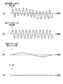
次に図6及び図7を用いて、S102及びS103の処理の効果について説明する。図6(a)は、撮像装置100のズーム倍率が広角端の状態で、ユーザーが歩行しながら撮影を行ったときの、撮像装置100に加わる振れ量の時間による変化を示したグラフである。図6(b)の点線のグラフは、図6(a)の振れによって生じる撮像面上のブレを100%補正するために必要な、補正光学系114の駆動位置の時間による変化を示している。図6(b)の実線のグラフは、図1の撮像装置100で、実際に補正光学系114によるブレ補正を行ったときの、補正光学系114の位置の時間による変化を示している。
Next, the effect of the processing of S102 and S103 will be described with reference to FIGS. FIG. 6A is a graph showing a change over time in the amount of shake applied to the
図6(b)の実線のグラフと点線のグラフに乖離があるのは、以下の理由に依る。第一に、レンズの大型化を防止するため、補正光学系114の可動範囲を、歩行時に生じる振れの最大値より狭くしていることによる。そのため、HPF104のカットオフ周波数及び積分器106の時定数設定によって、低周波数帯域の振れの抑振率を低くしている。このようにすることで、補正光学系114が光学補正データ出力制限部131のリミット値で決まる可動限界に達し、ブレ補正が急激に効かなくなってしまう現象が生じることを防止している。そのため、図6(b)の実線のグラフは点線のグラフと比較して、振幅が小さくなっており、低周波数帯域のブレを敢えて補正しないようにしている。第二に、上述したように、歩行時には静止状態と比較して撮像装置に対して大きな振動が加わるため、補正光学系114にも振動が生じてしまうことによる。これによって、図6(b)の実線のグラフは点線のグラフと比較して、高周波数帯域の振動が重畳した波形となっている。
The difference between the solid line graph and the dotted line graph in FIG. 6B is due to the following reason. First, in order to prevent an increase in the size of the lens, the movable range of the correction
図6(c)の点線のグラフは、図6(a)の振れによって生じる撮像面上のブレを、図6(b)の実線波形に従って補正光学系114を駆動して補正した後のブレ残りを、100%補正するための画像メモリ119の読み出し位置の、時間による変化を示している。図6(c)の実線のグラフは、図1の撮像装置100で、実際にメモリ読み出し制御部120によるブレ補正を行ったときの、画像メモリ119の読み出し位置の時間による変化を示している。
The dotted line graph of FIG. 6C shows the blur remaining after correcting the blur on the imaging surface caused by the shake of FIG. 6A by driving the correction
図2のS102では、図5(a)を用いて説明したように、広角端のHPF128のカットオフ周波数を、望遠端と比較して高く設定していた。つまり、HPF128において、低周波数帯域のブレ成分を減衰して、高周波数帯域のブレは減衰せずに出力するようにしていた。またS103では、図5(b)を用いて説明したように、広角端の積分器129の時定数を、望遠端と比較して小さく設定していた。つまり、積分器129において、低周波数帯域のブレ成分は減衰して積分し、高周波数帯域のブレは減衰せずに積分して出力するようにしていた。
In S102 of FIG. 2, as described with reference to FIG. 5A, the cutoff frequency of the
これによって、画像メモリ119の読み出し位置の時間による変化は、図6(c)の実線のグラフに示す波形となり、高周波数帯域の振動成分のみを補正することができる。歩行時の低周波数成分のブレを補正しない理由は、低周波数成分のブレは振幅が大きいため、電子補正データ出力制限部132のリミット値で決まる画像メモリ119の読み出し位置の限界に達してしまう頻度が非常に大きくなってしまうからである。また、低周波数帯域のブレはある程度残っていても、映像としては違和感は少ないが、高周波数帯域の振動が生じている映像は、見苦しい映像となってしまうため、補正することが好ましい。
As a result, the change of the reading position of the
図6(d)のグラフは、図6(a)の振れによって生じる撮像面上のブレを、図6(b)及び図6(c)の実線波形に従って補正した後に残る、映像のブレ残りの時間に依る変化を示している。上述したように、画像メモリ119の読み出し位置変更によって、高周波数帯域の振動を補正しているため、低周波数帯域のブレ残りのみが残った映像となる。従って、光学式手ブレ補正と電子式手ブレ補正を併用した、広角歩行撮影時に最適なブレ補正制御を実現することができる。
The graph of FIG. 6D shows the image blur remaining after the blur on the imaging surface caused by the shake of FIG. 6A is corrected according to the solid line waveform of FIGS. 6B and 6C. It shows changes over time. As described above, since the vibration in the high frequency band is corrected by changing the reading position of the
図7(a)は、撮像装置のズーム倍率が望遠端の状態で、ユーザーが静止した状態(歩行時ではない状態)で撮影を行ったときの、撮像装置100に加わる振れ量の時間による変化を示したグラフである。図7(a)のグラフは、体の揺れなどの低周波数帯域の振れに、手の震えなどの高周波数帯域の振れが重畳した波形となっている。
FIG. 7A shows a change with time of the amount of shake applied to the
図7(b)は、補正光学系114によるブレ補正を行ったときの、補正光学系114の位置の時間による変化を示している。角速度センサ102の出力には、一般的に低周波の揺らぎ成分が重畳されているため、HPF104あるいは積分器106によって、角速度センサ102の出力の低周波数成分を減衰している。これによって、補正光学系114の駆動量は、図7(b)に示すように、図7(a)の振れ量から低周波数成分を除去した波形となる。
FIG. 7B shows a change with time of the position of the correction
図7(c)は、メモリ読み出し制御部120によるブレ補正を行ったときの、画像メモリ119の読み出し位置の時間による変化を示している。図2のフローチャートのS102では、図5(a)を用いて説明したように、望遠端のHPF128のカットオフ周波数を、広角端と比較して低く設定していた。つまり、HPF128において、低周波数帯域のブレ成分を減衰せずに出力するようにしていた。またS103では、図5(b)を用いて説明したように、望遠端の積分器129の時定数を、広角端と比較して大きく設定していた。つまり、積分器129において、低周波数帯域から高周波数帯域のブレ成分まで減衰せずに積分して出力するようにしていた。
FIG. 7C shows a change with time of the reading position of the
これによって、画像メモリ119の読み出し位置の時間による変化は、図7(c)に示す波形となり、補正光学系114で補正しなかった低周波数帯域のブレ成分を補正することができる。ユーザーが静止した状態で望遠撮影を行ったときの低周波数帯域の像面上のブレは、歩行状態で広角撮影を行ったときの低周波数帯域の像面上のブレと比較すると小さい。そのため、前者で低周波数帯域のブレを、メモリ読み出し制御部120によって補正したときに、読み出し位置の限界に達してしまう頻度は、後者と比較して少ない。従って、広角側よりも低周波数帯域のブレまで補正した方が、ブレの少ない見やすい映像となるため、補正することが好ましい。
As a result, the change with time of the reading position of the
図7(d)のグラフは、図7(a)の振れによって生じる撮像面上のブレを、図7(b)及び図7(c)の波形に従って補正した後に残る、映像のブレ残りの時間に依る変化を示している。上述したように、画像メモリ119の読み出し位置変更によって、低周波数帯域の振動を補正しているため、低周波から高周波までブレ残りが少ない映像となる。これにより、光学式手ブレ補正と電子式手ブレ補正を併用した、望遠静止撮影時に最適なブレ補正制御を実現することができる。
The graph of FIG. 7D shows the remaining time of image blur remaining after correcting the blur on the imaging surface caused by the shake of FIG. 7A according to the waveforms of FIG. 7B and FIG. 7C. Shows changes due to As described above, since the vibration in the low frequency band is corrected by changing the reading position of the
以上説明してきたように、本発明の実施形態においては、メモリ読み出し制御部120の制御範囲を、広角側と望遠側で大きくし中間ズーム域では小さくするようにした。これによって、広角歩行撮影時と望遠静止撮影時両方のブレ補正性能を向上しつつ、レンズの小型化も実現することができる。また、広角側ではHPF128のカットオフ周波数を高く、あるいは積分器129の時定数を小さくし、望遠側ではHPF128のカットオフ周波数を低く、あるいは積分器129の時定数を大きくする。これにより、ズーム域によって最適なブレ補正制御を実現することができる。
As described above, in the embodiment of the present invention, the control range of the memory read
以上、本発明をその好適な実施形態に基づいて詳述してきたが、本発明はこれら特定の実施形態に限られるものではなく、この発明の要旨を逸脱しない範囲の様々な形態も本発明に含まれる。また、上述の実施形態の一部を適宜組み合わせてもよい。 Although the present invention has been described in detail based on preferred embodiments thereof, the present invention is not limited to these specific embodiments, and various forms within the scope of the present invention are also included in the present invention. included. Moreover, you may combine suitably a part of above-mentioned embodiment.
Claims (5)
ズームレンズの変倍位置を検出するズーム検出手段と、
装置の振れを検出する振れ検出手段と、
前記撮像手段によって撮像された画像から動きベクトルを検出するベクトル検出手段と、
前記振れに基づいて、第1の振れ補正量を求める第1の取得手段と、
前記動きベクトルに基づいて、第2の振れ補正量を求める第2の取得手段と、
前記第1の振れ補正量に基づいて、前記振れによる画像のブレを光学的に補正する第1の補正手段と、
前記第2の振れ補正量に基づいて、前記振れによる画像のブレを画像の切り出し範囲を変更することによって補正する第2の補正手段と、
前記ズームレンズの変倍位置が広角端と望遠端を含まない予め決められた範囲内にある場合に、前記範囲外にある場合よりも前記第1の振れ補正量及び前記第2の振れ補正量を抑制するように制御する制御手段と
を有することを特徴とする撮像装置。 An imaging means for imaging a subject image formed by the optical system;
Zoom detecting means for detecting a zoom position of the zoom lens;
Shake detection means for detecting the shake of the device;
Vector detection means for detecting a motion vector from an image captured by the imaging means;
First acquisition means for obtaining a first shake correction amount based on the shake;
Second acquisition means for obtaining a second shake correction amount based on the motion vector;
First correction means for optically correcting image blur due to the shake based on the first shake correction amount;
Second correction means for correcting image blur due to the shake by changing a cutout range of the image based on the second shake correction amount;
When the zooming position of the zoom lens is within a predetermined range that does not include the wide-angle end and the telephoto end, the first shake correction amount and the second shake correction amount are greater than when the zoom lens is outside the range. imaging apparatus characterized by a control means for controlling so as to win suppress the.
ズーム検出手段が、ズームレンズの変倍位置を検出するズーム検出工程と、
振れ検出手段が、前記撮像装置の振れを検出する振れ検出工程と、
ベクトル検出手段が、前記撮像手段によって撮像された画像から動きベクトルを検出するベクトル検出工程と、
第1の取得手段が、前記振れに基づいて、第1の振れ補正量を求める第1の取得工程と、
第2の取得手段が、前記動きベクトルに基づいて、第2の振れ補正量を求める第2の取得工程と、
制御手段が、前記ズームレンズの変倍位置が広角端と望遠端を含まない予め決められた範囲内にある場合に、前記範囲外にある場合よりも、前記第1の振れ補正量及び前記第2の振れ補正量を抑制するように制御する制御工程と、
第1の補正手段が、抑制された前記第1の振れ補正量に基づいて、前記振れを光学的に補正する第1の補正工程と、
第2の補正手段が、抑制された前記第2の振れ補正量に基づいて、前記振れを画像の切り出し範囲を変更することによって補正する第2の補正工程と、
を有することを特徴とする撮像装置の制御方法。 A method for controlling an image pickup apparatus having an image pickup means for picking up a subject image formed by an optical system,
A zoom detection step in which the zoom detection means detects the zoom position of the zoom lens;
A shake detection step in which the shake detection means detects the shake of the imaging device;
A vector detection step of detecting a motion vector from the image captured by the imaging means;
A first acquisition unit that obtains a first shake correction amount based on the shake;
A second obtaining step in which a second obtaining means obtains a second shake correction amount based on the motion vector;
When the zooming position of the zoom lens is within a predetermined range that does not include the wide-angle end and the telephoto end, the control means may detect the first shake correction amount and the first amount more than when the zoom lens is outside the range. and a control step of controlling so as to suppress win the shake correction amount of 2,
A first correction step in which a first correction unit optically corrects the shake based on the suppressed first shake correction amount;
A second correction step, wherein the second correction unit corrects the shake by changing a cutout range of the image based on the suppressed second shake correction amount;
A method for controlling an imaging apparatus , comprising:
Priority Applications (1)
| Application Number | Priority Date | Filing Date | Title |
|---|---|---|---|
| JP2011286629A JP5848603B2 (en) | 2011-12-27 | 2011-12-27 | Imaging apparatus and control method thereof |
Applications Claiming Priority (1)
| Application Number | Priority Date | Filing Date | Title |
|---|---|---|---|
| JP2011286629A JP5848603B2 (en) | 2011-12-27 | 2011-12-27 | Imaging apparatus and control method thereof |
Publications (3)
| Publication Number | Publication Date |
|---|---|
| JP2013135443A JP2013135443A (en) | 2013-07-08 |
| JP2013135443A5 JP2013135443A5 (en) | 2015-01-22 |
| JP5848603B2 true JP5848603B2 (en) | 2016-01-27 |
Family
ID=48911824
Family Applications (1)
| Application Number | Title | Priority Date | Filing Date |
|---|---|---|---|
| JP2011286629A Expired - Fee Related JP5848603B2 (en) | 2011-12-27 | 2011-12-27 | Imaging apparatus and control method thereof |
Country Status (1)
| Country | Link |
|---|---|
| JP (1) | JP5848603B2 (en) |
Families Citing this family (3)
| Publication number | Priority date | Publication date | Assignee | Title |
|---|---|---|---|---|
| CN108353131B (en) * | 2016-10-17 | 2021-05-04 | 华为技术有限公司 | Method and terminal device for acquiring image |
| KR102608782B1 (en) * | 2016-12-30 | 2023-12-04 | 삼성전자주식회사 | Device and Method for Compensating Motion Effect of an Electronic Device in an Image |
| CN113396578A (en) * | 2019-03-15 | 2021-09-14 | 索尼半导体解决方案公司 | Image pickup apparatus, solid-state image pickup element, camera module, drive control unit, and image pickup method |
Family Cites Families (4)
| Publication number | Priority date | Publication date | Assignee | Title |
|---|---|---|---|---|
| JPH11146260A (en) * | 1997-11-13 | 1999-05-28 | Canon Inc | Device and method for correcting oscillation and computer readable storage medium |
| JP3424063B2 (en) * | 1997-12-19 | 2003-07-07 | 松下電器産業株式会社 | Image motion compensation device |
| JP5276535B2 (en) * | 2009-07-15 | 2013-08-28 | キヤノン株式会社 | Image blur correction apparatus, optical apparatus including the same, image pickup apparatus, and image blur correction apparatus control method |
| JP5426952B2 (en) * | 2009-07-15 | 2014-02-26 | キヤノン株式会社 | Image shake correction apparatus, control method therefor, optical apparatus, and imaging apparatus |
-
2011
- 2011-12-27 JP JP2011286629A patent/JP5848603B2/en not_active Expired - Fee Related
Also Published As
| Publication number | Publication date |
|---|---|
| JP2013135443A (en) | 2013-07-08 |
Similar Documents
| Publication | Publication Date | Title |
|---|---|---|
| KR101322291B1 (en) | Image capturing apparatus and method of controlling image capturing apparatus | |
| JP6124588B2 (en) | Image blur correction apparatus, control method therefor, program, and storage medium | |
| JP5501119B2 (en) | Imaging apparatus and control method thereof | |
| JP6214316B2 (en) | Image blur correction device, lens device, imaging device, image blur correction device control method, program, and storage medium | |
| JP5409342B2 (en) | Imaging apparatus and control method thereof | |
| JP5959850B2 (en) | Imaging apparatus and control method thereof | |
| JP6581352B2 (en) | Image blur correction apparatus and control method thereof, imaging apparatus, lens apparatus, program, and storage medium | |
| JP2010147857A (en) | Imaging apparatus and imaging method, program and medium | |
| JP6204807B2 (en) | Image blur correction apparatus, control method therefor, program, and storage medium | |
| JP6659086B2 (en) | Image blur correction device, optical device, imaging device, and control method | |
| JP5848603B2 (en) | Imaging apparatus and control method thereof | |
| US10089745B2 (en) | Image processing apparatus that enables easy tracking of a subject if the subject moves to outside a field angle and control method for same | |
| JP6767618B2 (en) | Imaging device | |
| JP5441296B2 (en) | Imaging device and method for controlling diaphragm blades of imaging device | |
| JP6178573B2 (en) | Image blur correction apparatus, control method therefor, program, and storage medium | |
| JP2006074402A (en) | Imaging apparatus | |
| US11678052B2 (en) | Control apparatus, image pickup apparatus, control method, and storage medium | |
| JP6346653B2 (en) | Image blur correction apparatus, image blur correction method, program, and storage medium | |
| JP2005173161A (en) | Optical apparatus | |
| JP2014216863A (en) | Imaging apparatus and control method thereof |
Legal Events
| Date | Code | Title | Description |
|---|---|---|---|
| A521 | Request for written amendment filed |
Free format text: JAPANESE INTERMEDIATE CODE: A523 Effective date: 20141203 |
|
| A621 | Written request for application examination |
Free format text: JAPANESE INTERMEDIATE CODE: A621 Effective date: 20141203 |
|
| A977 | Report on retrieval |
Free format text: JAPANESE INTERMEDIATE CODE: A971007 Effective date: 20150928 |
|
| TRDD | Decision of grant or rejection written | ||
| A01 | Written decision to grant a patent or to grant a registration (utility model) |
Free format text: JAPANESE INTERMEDIATE CODE: A01 Effective date: 20151030 |
|
| A61 | First payment of annual fees (during grant procedure) |
Free format text: JAPANESE INTERMEDIATE CODE: A61 Effective date: 20151127 |
|
| R151 | Written notification of patent or utility model registration |
Ref document number: 5848603 Country of ref document: JP Free format text: JAPANESE INTERMEDIATE CODE: R151 |
|
| LAPS | Cancellation because of no payment of annual fees |