JP5844810B2 - Improved energy saving method in a device with rotating mass or reciprocating mass - Google Patents
Improved energy saving method in a device with rotating mass or reciprocating mass Download PDFInfo
- Publication number
- JP5844810B2 JP5844810B2 JP2013527068A JP2013527068A JP5844810B2 JP 5844810 B2 JP5844810 B2 JP 5844810B2 JP 2013527068 A JP2013527068 A JP 2013527068A JP 2013527068 A JP2013527068 A JP 2013527068A JP 5844810 B2 JP5844810 B2 JP 5844810B2
- Authority
- JP
- Japan
- Prior art keywords
- phase angle
- motor
- supply voltage
- period
- turn
- Prior art date
- Legal status (The legal status is an assumption and is not a legal conclusion. Google has not performed a legal analysis and makes no representation as to the accuracy of the status listed.)
- Expired - Fee Related
Links
Images


Classifications
-
- H—ELECTRICITY
- H02—GENERATION; CONVERSION OR DISTRIBUTION OF ELECTRIC POWER
- H02P—CONTROL OR REGULATION OF ELECTRIC MOTORS, ELECTRIC GENERATORS OR DYNAMO-ELECTRIC CONVERTERS; CONTROLLING TRANSFORMERS, REACTORS OR CHOKE COILS
- H02P1/00—Arrangements for starting electric motors or dynamo-electric converters
- H02P1/02—Details
- H02P1/04—Means for controlling progress of starting sequence in dependence upon time or upon current, speed, or other motor parameter
-
- H—ELECTRICITY
- H02—GENERATION; CONVERSION OR DISTRIBUTION OF ELECTRIC POWER
- H02P—CONTROL OR REGULATION OF ELECTRIC MOTORS, ELECTRIC GENERATORS OR DYNAMO-ELECTRIC CONVERTERS; CONTROLLING TRANSFORMERS, REACTORS OR CHOKE COILS
- H02P23/00—Arrangements or methods for the control of AC motors characterised by a control method other than vector control
- H02P23/0004—Control strategies in general, e.g. linear type, e.g. P, PI, PID, using robust control
-
- H—ELECTRICITY
- H02—GENERATION; CONVERSION OR DISTRIBUTION OF ELECTRIC POWER
- H02P—CONTROL OR REGULATION OF ELECTRIC MOTORS, ELECTRIC GENERATORS OR DYNAMO-ELECTRIC CONVERTERS; CONTROLLING TRANSFORMERS, REACTORS OR CHOKE COILS
- H02P23/00—Arrangements or methods for the control of AC motors characterised by a control method other than vector control
- H02P23/24—Controlling the direction, e.g. clockwise or counterclockwise
-
- H—ELECTRICITY
- H02—GENERATION; CONVERSION OR DISTRIBUTION OF ELECTRIC POWER
- H02P—CONTROL OR REGULATION OF ELECTRIC MOTORS, ELECTRIC GENERATORS OR DYNAMO-ELECTRIC CONVERTERS; CONTROLLING TRANSFORMERS, REACTORS OR CHOKE COILS
- H02P6/00—Arrangements for controlling synchronous motors or other dynamo-electric motors using electronic commutation dependent on the rotor position; Electronic commutators therefor
- H02P6/14—Electronic commutators
- H02P6/16—Circuit arrangements for detecting position
- H02P6/18—Circuit arrangements for detecting position without separate position detecting elements
- H02P6/182—Circuit arrangements for detecting position without separate position detecting elements using back-emf in windings
-
- H—ELECTRICITY
- H02—GENERATION; CONVERSION OR DISTRIBUTION OF ELECTRIC POWER
- H02P—CONTROL OR REGULATION OF ELECTRIC MOTORS, ELECTRIC GENERATORS OR DYNAMO-ELECTRIC CONVERTERS; CONTROLLING TRANSFORMERS, REACTORS OR CHOKE COILS
- H02P6/00—Arrangements for controlling synchronous motors or other dynamo-electric motors using electronic commutation dependent on the rotor position; Electronic commutators therefor
- H02P6/28—Arrangements for controlling current
Description
[関連出願の参照]
本出願は、同時係属している2010年9月1日出願の米国特許出願第12/873,510号の一部継続出願であり、当該継続出願は、2009年9月8日出願の米国特許仮出願第61/240,399号の利益を主張する。これらの出願は全て、あらゆる目的において、参照を以てその全体が本明細書の一部となる。
[Reference to related applications]
This application is a continuation-in-part of co-pending US patent application Ser. No. 12 / 873,510 filed on Sep. 1, 2010, which is a US patent filed on Sep. 8, 2009. Claims the benefit of
[連邦政府資金による研究開発の記載]
なし
[Federal funded research and development description]
None
[マイクロフィッシュアペンディックスの引用]
なし
[Quote of microfish appendix]
None
1.技術分野 1. Technical field
本発明は、回転質量(rotating masses)又は往復質量(reciprocating masses)を有するポンプジャック(pump jack)及び他の装置を動作するのに用いられる電気モータに関する。 The present invention relates to a pump jack having rotating masses or reciprocating masses and an electric motor used to operate other devices.
2.背景技術 2. Background art
ポンプジャックは、油井(oil well)の下げ孔(downhole)に設置されたピストンポンプを往復運動させる地上の駆動装置である。ポンプジャックは、液体がそれ自身で地表面へ向けて流れる程十分な坑底圧(bottom hole pressure)がない場合、液体を井戸から機械的に持ち上げる。ポンプジャックは、大抵の場合、公共電力網(electric utility grid)から給電される電気モータで動く。ポンプジャックは、モータの回転機構を垂直往復運動に変換して、坑井内ホールポンプ(downhole pump)を駆動する。様々な設計のポンプジャックが存在しており、従来型、Lufkin Mark II型、ビームバランス(beam-balanced)型、エアーバランス(air-balanced)型、斜孔(slant hole)型や従来の可搬型があるが、これらに限られない。ポンプジャックは様々な供給業者から市販されており、Lufkin Industries社(テキサス州ラフキン)やCook Pump社(カンザス州コフィービル)が含まれる。 The pump jack is a ground drive device that reciprocates a piston pump installed in a downhole of an oil well. The pump jack mechanically lifts the liquid from the well if there is not enough bottom hole pressure to allow the liquid to flow itself towards the ground. The pump jack is usually driven by an electric motor powered by an electric utility grid. The pump jack drives a downhole pump by converting the rotation mechanism of the motor into a vertical reciprocating motion. There are pump jacks of various designs, conventional type, Lufkin Mark II type, beam-balanced type, air-balanced type, slant hole type and conventional portable type There is, but is not limited to these. Pump jacks are commercially available from a variety of suppliers and include Lufkin Industries (Luffkin, Texas) and Cook Pump (Coffeyville, Kansas).
ポンプジャックの電気モータは通常、一連のプーリーをギア機構又はギアトランスミッションに対して回転させる。次いで、ギア機構又はギアトランスミッションは、一対のクランク又はクランクアームを駆動する。典型的な従来型ポンプジャックの設計では、クランクは、レバー又はビームの一端を上げ下げする。このレバー又はビームは、「移動ビーム(walking beam)」として知られ、サンプソンポスト又はA字形フレーム上に枢支されている。「ホースヘッド(horse head)」として知られる湾曲した金属製ボックスが、移動ビームの他端に存在しており、クランクアームは、そこからビームと接続される。通常、カウンターウェイト又は往復質量が、クランクの一端に取り付けられる。通常、ピットマンアーム(pitman arm)が、カウンターウェイトと、ホースヘッドとは反対側の移動ビーム端部との間に架かっている。ケーブルが、ホースヘッドを垂直な研磨ロッド(polished rod)に接続している。研磨ロッドは、坑井内ポンプに及ぶ管又はサッカーロッド(sucker rods)の垂直な列に接続されている。 The electric motor of the pump jack typically rotates a series of pulleys relative to the gear mechanism or gear transmission. The gear mechanism or gear transmission then drives a pair of cranks or crank arms. In a typical conventional pump jack design, the crank raises and lowers one end of the lever or beam. This lever or beam is known as the “walking beam” and is pivoted on a Sampson post or A-shaped frame. A curved metal box, known as a “horse head”, is present at the other end of the moving beam, from which the crank arm is connected to the beam. A counterweight or reciprocating mass is usually attached to one end of the crank. Usually, a pitman arm is placed between the counterweight and the end of the moving beam opposite the hose head. A cable connects the hose head to a vertical polished rod. The abrasive rod is connected to a vertical row of tubes or sucker rods that span the well pump.
カウンターウェイトは、モータがサッカーロッドの列又は管の列を持ち上げるのを助力する。モータがカウンターウェイトを持ち上げると、ホースヘッドは下方に移動し、サッカーロッド又は管の列を押し下げる。カウンターウェイトは、その回転の最上位置に達した後に、カウンターウェイトの運動量及び質量(運動エネルギー)によってスイングし、モータが移動ビームを反対方向に回転させるのを助力する。カウンターウェイトがその最上位置から下方へ自由落下する際、ホースヘッドは上方へ移動し、サッカーロッドの列を持ち上げる。米国特許第4,051,736号は、油井ポンプを往復運動させる改良型ポンプジャックを提案している。 The counterweight helps the motor to lift the row of soccer rods or the row of tubes. As the motor lifts the counterweight, the hose head moves downward, pushing down the soccer rod or tube row. After reaching the uppermost position of the rotation of the counterweight, the counterweight is swung by the momentum and mass (kinetic energy) of the counterweight to help the motor rotate the moving beam in the opposite direction. As the counterweight falls freely downward from its uppermost position, the hose head moves upward and lifts the row of soccer rods. U.S. Pat. No. 4,051,736 proposes an improved pump jack that reciprocates an oil well pump.
様々な抗井内ポンプの設計が存在するが、抗井内ポンプは従来より、プロダクションチュービングの端部付近に配置したポンプ胴内を往復運動するプランジャ又はピストンを含んでいる。通常、2つの独立したバルブがポンプ作用を達成する。スタンディング逆止バルブがピストンの下でポンプ胴に固定され、ピストンは、トラベリング逆止バルブを備えてよい。ピストンのアップストロークは、スタンディングバルブを開き、トラベリングバルブが閉じたままであると、流体をポンプ胴内に引き込む。ピストンのダウンストロークは、トラベリングバルブを開き、スタンディングバルブが閉じたままであると、流体をポンプ胴から押し上げる。米国特許第3,578,886号、米国特許第4,173,451号、及び米国特許第6,904,973号は、抗井内ポンプを提案している。 Various in-well pump designs exist, but in-well pumps conventionally include a plunger or piston that reciprocates within a pump barrel located near the end of a production tubing. Usually two independent valves achieve the pumping action. A standing check valve is secured to the pump body under the piston, and the piston may comprise a traveling check valve. The up stroke of the piston opens the standing valve and draws fluid into the pump cylinder if the traveling valve remains closed. The piston downstroke opens the traveling valve and pushes fluid out of the pump barrel if the standing valve remains closed. U.S. Pat. No. 3,578,886, U.S. Pat. No. 4,173,451, and U.S. Pat. No. 6,904,973 propose in-well pumps.
電気モータがエネルギー発生動作モードに入り得ることがよく知られている。ポンプジャックに用いられる電気モータでは、エネルギー発生モードは、カウンターウェイトと管又はロッドの列とのバランスの状態に応じて、カウンターウェイト回転中の如何なる時でも起こり得る。バランスの状態は、各ストロークにおいてロッド列によって持ち上げられる流体の量及び組成に応じて、ポンプのストローク毎に変動し得る。研磨ロッド及び付属のサッカーロッド又は管の列は、エネルギー発生モードにおいて上下に移動し得る。 It is well known that an electric motor can enter an energy generation mode of operation. In an electric motor used in a pump jack, the energy generation mode can occur at any time during counterweight rotation, depending on the balance between the counterweight and the row of tubes or rods. The state of balance may vary from pump stroke to pump stroke, depending on the amount and composition of the fluid lifted by the rod train at each stroke. The abrasive rod and the attached soccer rod or tube row can move up and down in the energy generation mode.
井戸の所有者は、ポンプジャックのモータが消費する電力量に基づいて電気代を支払わなければならない。消費されたエネルギー量は、エネルギーメータによって測定される。これまで、消費電力量は、アナログ式電気メータによって測定されていた。現在、多くのデジタル式電気メータが使用されている。エネルギーメータは、アナログ設計又はデジタル設計に拘わらず、公益事業会社の裁量で、送電網(power grid)に戻るように供給される発生エネルギーを消費者に帰属させる、又はしないように設定できる。ポンプジャックシステムは、非効率的な発生機であって、発生するのに必要な消費エネルギー量は、発生エネルギーを大きく超える。従って、公益事業会社が発生エネルギーをクレジットするか否かに拘わらず、消費者がエネルギー発生を避けることは常に有益である。 The owner of the well must pay for electricity based on the amount of power consumed by the pump jack motor. The amount of energy consumed is measured by an energy meter. Until now, power consumption has been measured with an analog electric meter. Currently, many digital electric meters are used. Regardless of analog or digital design, the energy meter can be set so that the energy generated supplied back to the power grid is attributed to the consumer or not at the discretion of the utility company. The pump jack system is an inefficient generator, and the amount of energy required to be generated greatly exceeds the generated energy. Therefore, it is always beneficial for consumers to avoid generating energy, regardless of whether the utility company credits the generated energy.
発生周期中、モータは、商用電力の線間電圧を超える電圧に達しようとし、これによって電流を反対方向に流す。送電系統によって与えられる負荷がブレーキとして機能し、そうでなければ生じていたであろうモータの加速を制限している。このモータのブレーキ作用は、ポンプジャックの落錘(falling weights)が、ポンプ作用を助力していたであろう更なる運動エネルギーを生じさせることを防止する。この変換された運動エネルギーは、送電系統からの電気エネルギーの代わりとして機能したかも知れない。 During the generation cycle, the motor tries to reach a voltage exceeding the line voltage of the commercial power, thereby causing the current to flow in the opposite direction. The load provided by the transmission system functions as a brake, limiting the acceleration of the motor that would otherwise have occurred. This braking action of the motor prevents the falling weights of the pump jack from producing further kinetic energy that would have helped the pumping action. This converted kinetic energy may have served as a substitute for electrical energy from the transmission system.
これまで、技術者達は、発生周期を含んでいたであろうポンプジャックサイクルの一部の間に、ポンプジャックの電気モータをオフにすることによって、かなりのエネルギー量を節約しようとしてきたが、上手くいかなかった。これは、種々の機械スイッチ及びリレーにより試みられてきた。しかし、抗井内ポンプ及び井戸のパラメータが時間と共に変化するので、これらの機械的な解決策は上手くいかなかった。 So far, engineers have tried to save a significant amount of energy by turning off the pump jack's electric motor during the portion of the pump jack cycle that would have included the generation cycle, It did n’t work. This has been attempted with various mechanical switches and relays. However, these mechanical solutions did not work because the in-well pump and well parameters changed over time.
井戸内の流体の流れが、井戸が満ちるに従って変化して、その後「ポンプオフ(pumps off)」し得る。ある場合には、汲み上げられる流体の体積は、ストロークごとに変化し得る。汲み上げられるガス、油、水やスラリー等の物質及び/又は流体の体積、密度、粘度、重量や他の特性の変化は、ロッド列と流体のカラムとを合わせた重量を大きく変更し得る。これによって、システムのバランスとモータの負担に影響を及ぼす。一部の井戸では、管の列が何千フィートもの長さであり得る。異なる流体の井戸への流入は、モータの動作に多大な影響を及ぼすであろう。 The fluid flow in the well may change as the well fills and then “pumps off”. In some cases, the volume of fluid pumped may change from stroke to stroke. Changes in the volume, density, viscosity, weight, and other properties of substances and / or fluids such as pumped gas, oil, water and slurry can greatly change the combined weight of the rod row and fluid column. This affects the balance of the system and the burden on the motor. In some wells, the tube rows can be thousands of feet long. The flow of different fluids into the well will have a significant impact on motor operation.
マイクロプロセッサの導入により、電流及び電圧を監視して電気モータをオフにすることが可能となった。しかしながら、電気モータをオンに戻す場合の問題が知られていた。これまで、様々な開ループの一定の時間遅延が試みられたが、抗井内ポンプと井戸のパラメータが時間と共に変化するので、これらの試みは上手くいかなかった。適切な時間でモータをオンに戻すことができないと、エネルギー節減を減少させるか、又はその他の望ましくない効果を引き起こすことがある。 With the introduction of a microprocessor, the electric motor can be turned off by monitoring the current and voltage. However, problems with turning the electric motor back on have been known. So far, constant time delays of various open loops have been attempted, but these attempts have not been successful as the in-well pump and well parameters change over time. Failure to turn the motor back on at the proper time may reduce energy savings or cause other undesirable effects.
AC誘導モータの負荷が少ない場合、供給される電圧を減少することで、モータをより効率的に動作させてエネルギーが節約される。これは、特に、単相モータで明らかであり、より程度は低いが、三相モータの場合でも明らかである。大きな三相モータは、モータの定格負荷の約3分の1よりも大きいあらゆる負荷において、通常、自ずと効率的である。 When the load on the AC induction motor is low, reducing the supplied voltage will allow the motor to operate more efficiently and save energy. This is particularly apparent with single-phase motors, and to a lesser extent with a three-phase motor. Large three-phase motors are usually naturally efficient at any load greater than about one third of the rated load of the motor.
モータに印加された電圧と電流の間の位相角の変化は、モータが引き出す電力に対して反比例の関係にある。高い位相角は、軽負荷のモータを示し、低い位相角は、重装負荷モータを示す。 The change in phase angle between the voltage and current applied to the motor is inversely proportional to the power drawn by the motor. A high phase angle indicates a lightly loaded motor and a low phase angle indicates a heavily loaded motor.
大半のポンプジャックは、5馬力(HP)と同程度に小さい3相モータ、しかしながら、通常は、20馬力以上である3相モータを使用している。これらのモータは、5秒から12秒の範囲の期間で、周期的に変化する負荷を受ける。通常のポンプストロークの間、モータは、1回又は2回重い負荷と、1回又は2回軽い負荷とを受ける。ポンプジャックの形状とバランスに応じて、落錘(カウンターウェイト又はロッド列の何れか)は、その同期速度を超えてモータを駆動することができ、それにより、それをジェネレータとして機能させる。その時間の間、位相角は、90度を超える。 Most pump jacks use a three-phase motor as small as five horsepower (HP), but usually a three-phase motor that is over 20 horsepower. These motors are subjected to periodically changing loads over a period ranging from 5 seconds to 12 seconds. During a normal pump stroke, the motor is subjected to a heavy load once or twice and a light load once or twice. Depending on the shape and balance of the pump jack, the falling weight (either counterweight or rod train) can drive the motor beyond its synchronous speed, thereby making it function as a generator. During that time, the phase angle exceeds 90 degrees.
米国特許第6,489,742号は、デジタル信号プロセッサを用いた誘導モータへの電力輸送を含むモータコントローラを提案しており、該デジタル信号プロセッサは、電源電圧(power supply and main voltage)からの現下のモータ負荷への電流供給を、制御要素によって計算及び最適化する。米国出願出願公開第2010/0117588は、AC誘導モータのエネルギーを負荷毎に節約するモータコントローラ及び方法を提案しており、モータが2又はそれより多い負荷ポイントで較正されて、制御ラインを確立し、その後、当該制御ラインが、モータコントローラの不揮発性のメモリにプログラムされる。 U.S. Pat. No. 6,489,742 proposes a motor controller that includes power transfer to an induction motor using a digital signal processor, the digital signal processor from a power supply and main voltage. The current supply to the current motor load is calculated and optimized by the control element. US Published Application 2010/0117588 proposes a motor controller and method that conserves the energy of an AC induction motor per load, where the motor is calibrated at two or more load points to establish a control line. Thereafter, the control line is programmed into the nonvolatile memory of the motor controller.
米国特許出願公開第2009/0046490号は、IGBT/FETベースのエネルギー節約装置、システム及び方法を提案しており、公称線間電圧及び/又は公称家電電圧を下回る所定量の電圧が節約される。米国特許出願公開第2009/0051344号は、TRIAC/SCRベースのエネルギー節約装置、システム及び方法を提案しており、公称線間電圧及び/又は公称家電電圧を下回る所定量の電圧が節約される。米国特許出願公開第2009/0200981号は、AC電圧印加において一定負荷を与えるシステム及び方法を提案しており、変調正弦波(modulating sine wave)の少なくとも2分の1のサイクルの少なくとも1つのターンオン点(turn-on point)が決定され、変調正弦波の少なくとも2分の1のサイクルの少なくとも1つのターンオフ点(turn-off point)が決定され、そして少なくとも1つのターンオン点と少なくとも1つのターンオフ点との間に位置する少なくとも1つのスライス(slice)が除かれる。米国特許出願公開第2010/0033155号は、IGBT/FETドライバ用の電源を提案しており、各IGBT/FETドライバへ個々に絶縁電力(isolated power)を供給する。 US 2009/0046490 proposes an IGBT / FET-based energy saving device, system and method that saves a certain amount of voltage below the nominal line voltage and / or nominal home appliance voltage. US 2009/0051344 proposes a TRIAC / SCR based energy saving device, system and method that saves a certain amount of voltage below the nominal line voltage and / or nominal appliance voltage. U.S. Patent Application Publication No. 2009/0200981 proposes a system and method for providing a constant load when applying an AC voltage, wherein at least one turn-on point of at least one-half cycle of a modulating sine wave. (turn-on point) is determined, at least one turn-off point of at least one-half cycle of the modulated sine wave is determined, and at least one turn-on point and at least one turn-off point At least one slice located between is removed. US 2010/0033155 proposes a power supply for an IGBT / FET driver, which provides isolated power to each IGBT / FET driver individually.
アルゴリズム及びフィードバック機構を制御するのに広く用いられる技術として、比例-積分-微分(PID)制御がある。一般的に呼ばれるPIDコントローラは、「誤差(error)」に基づいて値を計算する。通常、「誤差」は、測定されるプロセス変数と、所望の設定値又は目標値との差として計算される。PIDコントローラは、プロセス制御変数を調整することによって、誤差を最小にしようと試みる。基本的に、PIDコントローラは、比例、積分及び微分パラメータを有するデジタルフィルターである。比例値は電流誤差に対する応答を決定し、積分値は最新の誤差の和に基づく応答を決定し、そして微分値は誤差が変化してきたレートに基づく応答を決定する。 A widely used technique for controlling algorithms and feedback mechanisms is proportional-integral-derivative (PID) control. A commonly called PID controller calculates a value based on "error". Typically, “error” is calculated as the difference between the measured process variable and the desired setpoint or target value. The PID controller attempts to minimize the error by adjusting process control variables. Basically, a PID controller is a digital filter with proportional, integral and derivative parameters. The proportional value determines the response to the current error, the integral value determines the response based on the sum of the most recent errors, and the derivative value determines the response based on the rate at which the error has changed.
上述の米国特許第3,578,886号、米国特許第4,051,736号、米国特許第4,173,451号、米国特許第6,489,742号、米国特許第6,904,973号、米国特許出願公開第2009/0046490号、米国特許出願公開第2009/0051344号、米国特許出願公開第2009/0200981号、米国特許出願公開第2010/0033155号及び米国特許出願公開第2010/0117588号は、あらゆる目的において、参照によってその全体が本明細書の一部となる。 US Pat. No. 3,578,886, US Pat. No. 4,051,736, US Pat. No. 4,173,451, US Pat. No. 6,489,742, US Pat. No. 6,904,973 US Patent Application Publication No. 2009/0046490, US Patent Application Publication No. 2009/0051344, US Patent Application Publication No. 2009/0200981, US Patent Application Publication No. 2010/0033155, and US Patent Application Publication No. 2010/0117588. The issue is hereby incorporated by reference in its entirety for all purposes.
ポンプジャックの電気モータのエネルギー使用を、特にエネルギー発生モード中にて、効率的に管理する要望がある。可能であれば、エネルギー発生モードをほとんど取り除くことが望ましい。 There is a need to efficiently manage the energy usage of the electric motor of the pump jack, especially during the energy generation mode. If possible, it is desirable to remove most energy generation modes.
ポンプジャック電気モータには、完全な未修正の線間電圧が供給され、モータコントローラは、位相角を監視する。位相角が所定の閾値位相角を超えることが監視された場合、モータは、非常に軽い負荷を受けており、今まさに、エネルギー発生モードに入ろうとしていると考えられる。これは、起こり得るターンオフ時間であると考えられる。閾値位相角を超えると、閉ループモータコントローラシステムは、ポンプジャック電気モータへの供給電圧を制御するように駆動される。モータへの供給電圧の制御によって、監視位相角は、目標位相角を超えない値で維持される The pump jack electric motor is supplied with a complete uncorrected line voltage and the motor controller monitors the phase angle. If the phase angle is monitored to exceed a predetermined threshold phase angle, the motor is under a very light load and is now considered to be in the energy generation mode. This is considered a possible turn-off time. When the threshold phase angle is exceeded, the closed loop motor controller system is driven to control the supply voltage to the pump jack electric motor. By controlling the supply voltage to the motor, the monitored phase angle is maintained at a value that does not exceed the target phase angle.
主要な応答特性である幾らかの電流を許容することによって、閉ループ制御システムが作動したままにされて、監視可能なフィードバックパラメータがモータ負荷状態の指標として使用される。状態に対してモータコントローラが反応し、負荷が増加して供給電圧を増加することが必要なときに、電力を供給できる。増加したモータの負荷状態の指標は、モータ制御のスイッチングデバイスを制御するのに用いた所定の閾値点弧角を下回る減少から検出される。これは、起こり得るターンオン時間として考えられる。上記のプロセスは、複数のポンプサイクルを繰り返して、一貫性が確保される。近い相関が観察された場合、システムは、開ループオン−オフ状態に入る。 By allowing some current, which is a key response characteristic, the closed-loop control system is left active and a monitorable feedback parameter is used as an indicator of motor load conditions. Power can be supplied when the motor controller reacts to the condition and the load increases and it is necessary to increase the supply voltage. The increased motor load condition index is detected from a decrease below a predetermined threshold firing angle used to control the motor controlled switching device. This is considered as a possible turn-on time. The above process is repeated for multiple pump cycles to ensure consistency. If a close correlation is observed, the system enters an open loop on-off state.
オン−オフ状態において、各ポンプストロークの間、位相角が監視され、閉ループ制御の間に予期された時間で確立されたターンオフ閾値を超えることが保証される。位相角が予期したタイミングを満たさない場合は、システムは、閉ループ制御に戻り、測定を繰り返す。予期したタイミングを満たす場合、モータに供給される電圧は、閉ループ制御から確立されたターンオフ時間で、完全にオフにされる。確立されたターンオン時間に戻った後直ちに、監視位相角が評価されて、所定の理想位相角と比較される。監視位相角が、理想値よりも高い場合、電圧が、より長い間オフのままにできていたことを示している。監視位相角が、理想値よりも低い場合、電圧は、より早くオンにされているべきであった。オフ期間が調節されて、次のストロークにおいての動作を最適化する。モータへの電圧は、予期された次のオフ時間迄、完全にオンのままにされる。 In the on-off state, the phase angle is monitored during each pump stroke to ensure that the turn-off threshold established at the expected time during closed-loop control is exceeded. If the phase angle does not meet the expected timing, the system returns to closed loop control and repeats the measurement. If the expected timing is met, the voltage supplied to the motor is completely turned off with a turn-off time established from closed loop control. Immediately after returning to the established turn-on time, the monitored phase angle is evaluated and compared to a predetermined ideal phase angle. If the monitoring phase angle is higher than the ideal value, it indicates that the voltage has been left off for a longer time. If the monitoring phase angle was lower than the ideal value, the voltage should have been turned on earlier. The off period is adjusted to optimize operation on the next stroke. The voltage to the motor remains fully on until the expected next off time.
本システムは、周期的に、強制的に閉ループ制御に戻り、タイミングを再評価する。タイミングに少しの変化しかない又は変化がない場合、小さく調節されて又は調節されずに、システムは開ループのオンオフ状態に戻る。閉ループ制御タイミングにおいて、かなりの変化がある場合、次に、システムは一貫的又は反復的なタイミングパターンが監視されるまで、閉ループ制御のままにされ、そのポイントで、システムは、新しいオフ及びオン時間で、開ループオン−オフ状態に戻る。 The system periodically returns to closed-loop control and re-evaluates timing. If there is little or no change in timing, the system returns to an open-loop on-off state with or without minor adjustments. If there is a significant change in the closed-loop control timing, then the system is left in closed-loop control until a consistent or repetitive timing pattern is monitored, at which point the system will have new off and on times. Return to the open loop on-off state.
このシステムと方法は、ポンプジャック用途におけるモータの負荷の高周期的な変化に対して利点がある。このシステムと方法は、モータへの電源が完全にオフにされるポンプストロークの間のこれらの時間に加えて、電源が再印加される適切な時間を正確に予想する。モータに対する電源の完全なオフは、優れたエネルギー節減をもたらす。 This system and method is advantageous for high periodic changes in motor load in pump jack applications. This system and method accurately predicts the appropriate time that power is reapplied in addition to these times during the pump stroke when the power to the motor is completely turned off. A complete power off to the motor provides excellent energy savings.
このシステムと方法は、印加された電圧と消費された電流との間の監視位相角に基づいたポンプジャックモータの負荷の周期的な変化を監視して、特徴づける手段を提供する。一旦、負荷が特徴づけられると、各ストロークの一部の間、モータをオフにすることによって、エネルギーを節約する機会が存在するかどうかを決定する。このシステムと方法は、この機会が次のポンプストロークの何時に生じるかを予想し、モータをオフにし、再びモータをオンにする設定として、次のポンプストロークに適合する基準を規定する。ポンプジャックの振る舞いの段階的な変化に順応して調節するアルゴリズムが実施され、この振る舞いにおける突然の大きな変化を認識して応答する保護が実施される。 The system and method provide a means to monitor and characterize periodic changes in pump jack motor load based on the monitored phase angle between applied voltage and consumed current. Once the load is characterized, it is determined whether there is an opportunity to save energy by turning off the motor for a portion of each stroke. The system and method anticipates when this opportunity will occur and defines the criteria to match the next pump stroke as a setting to turn off the motor and turn on the motor again. An algorithm is implemented that adapts and adjusts to gradual changes in pump jack behavior, and protection is provided that recognizes and responds to sudden large changes in this behavior.
本発明のより良い更なる理解は、図面において開示される種々の実施形態の、以下の詳細な記載によって得られる。図面において、同様の部分には同様の参照符号が与えられている。 A better understanding of the present invention can be obtained by the following detailed description of various embodiments disclosed in the drawings. In the drawings, like parts are given like reference numerals.
図1に、デジタル信号プロセッサ(DSP)(1)、及びハードウェア入出力のブロック図を示す。DSP(1)は、モータの動作特性を監視し、閉ループ制御下で作動中のモータについて、二乗平均平方根(RMS)電圧の補正を行うことができる。ハードウェア入力(2)は、相ゼロクロス入力(phase zero crossing inputs)(36)、位相線間電圧(phase line voltage)(37)、相モータ電圧(phase motor voltage)(38)及び電流(9)を取り込んでおり、DSP(1)を通過して処理されて、電力制御装置出力(14)を介して電力制御装置に至る。 FIG. 1 shows a block diagram of a digital signal processor (DSP) (1) and hardware input / output. The DSP (1) can monitor the operational characteristics of the motor and correct the root mean square (RMS) voltage for the motor operating under closed loop control. Hardware inputs (2) are phase zero crossing inputs (36), phase line voltage (37), phase motor voltage (38) and current (9) Is processed through the DSP (1) and reaches the power control device via the power control device output (14).
図2に、DSPに基づくモータコントローラ(4)のシステム及び方法のブロック図を示す。先ず、モータコントローラ(4)は、A相、B相及びC相の各々の電圧(37)及び電流(9)を読み、ゼロクロス入力(36)を取り込む。この時点で、電圧(13)及び電流(9)は、コンバータ(62)を用いてアナログからデジタルに変換されてよい。次に、各相についてモータ位相角の計算値(63)が計算されて、監視位相角(5)がもたらされる。次に、予めプログラムされた制御ライン(6)から導かれた目標位相角(10)が、監視位相角(5)と比較される。目標位相角(10)と監視位相角(5)の差は、結果として位相誤差信号(11)(28)を生じさせ、位相誤差信号(11)(28)は、PIDコントローラ(12)によって処理される。PIDコントローラ(12)は、比例、積分及び微分要素を備える。PIDコントローラ(12)からの出力は、TRIAC、SCR、IGBT又はMOSFETなどの電力制御装置(33)を用いて得られるモータ(3)への新たな制御電圧(13)(29)となり、線間電圧(50)が供給されるRMSモータ電圧(13)の電力制御装置出力(14)を、各相についてエネルギー節約が最大となるようにもたらすことができる。
FIG. 2 shows a block diagram of the system and method of the DSP-based motor controller (4). First, the motor controller (4) reads the voltage (37) and current (9) of each of the A phase, B phase and C phase, and takes in the zero cross input (36). At this point, voltage (13) and current (9) may be converted from analog to digital using converter (62). Next, a calculated value (63) of the motor phase angle is calculated for each phase, resulting in a monitored phase angle (5). Next, the target phase angle (10) derived from the preprogrammed control line (6) is compared with the monitoring phase angle (5). The difference between the target phase angle (10) and the monitored phase angle (5) results in a phase error signal (11) (28), which is processed by the PID controller (12). Is done. The
この閉ループシステムにおいて、モータ(3)の各相の電圧(13)及び電流は、継続的に監視される。モータコントローラ(4)は、モータへの負荷に応じて、監視位相角(5)を較正制御ライン(6)上の点に導く。この時点で、最大のエネルギー節約が実現される。というのも、制御ライン(6)は、モータ(3)からの既知の較正データに基づくからである。モータコントローラ(4)は、技術者が手作業で電圧(13)を設定するかのように、モータ(3)を制御することができる。違っているのは、DSP(1)は、リアルタイムの負荷の変化に動的に対応し、サイクル単位でこれらの調整ができることである。 In this closed loop system, the voltage (13) and current of each phase of the motor (3) are continuously monitored. The motor controller (4) guides the monitoring phase angle (5) to a point on the calibration control line (6) according to the load on the motor. At this point, maximum energy savings are realized. This is because the control line (6) is based on known calibration data from the motor (3). The motor controller (4) can control the motor (3) as if the engineer manually set the voltage (13). The difference is that DSP (1) dynamically responds to real-time load changes and allows these adjustments on a cycle-by-cycle basis.
図3を参照すると、三相システムにおいて、モータコントローラ(4)は、相回転を自動的に決定するのに使用される。線間電圧のゼロ-クロス検知器が、A相線間電圧ゼロクロス(15)とB相線間電圧ゼロクロス(16)との間の角度を正確に測定する。正の相回転(18)について、その角度は公称120度であり、負の相回転(19)について、その角度は公称60度である。 Referring to FIG. 3, in a three-phase system, the motor controller (4) is used to automatically determine the phase rotation. A line voltage zero-cross detector accurately measures the angle between the A phase line voltage zero cross (15) and the B phase line voltage zero cross (16). For positive phase rotation (18), the angle is nominally 120 degrees and for negative phase rotation (19), the angle is nominally 60 degrees.
図4に、相回転検知のフローチャートを示す。パワー-オン-リセット(POR)(20)の後、モータコントローラ(4)が正の相回転(18)及び負の相回転(19)を決定することは容易である。先ず、A相線間電圧ゼロクロスからB相線間電圧ゼロクロスまでの時間が測定される(39)。次に、その時間が90度よりも大きいか90度未満であるかが判定される(40)。時間が90度よりも大きい場合、ACB回転となる(42)。時間が90度未満である場合、ABC回転となる(41)。モータコントローラ(4)は、同じ基本ソフトウェア及びハードウェアアーキテクチャによって三相モータ又は単相モータを制御できる。三相の場合、モータコントローラ(4)は、相回転に応じて電力制御装置出力(14)を駆動できる。 FIG. 4 shows a flowchart of phase rotation detection. After power-on-reset (POR) (20), it is easy for the motor controller (4) to determine the positive phase rotation (18) and the negative phase rotation (19). First, the time from the A phase line voltage zero cross to the B phase line voltage zero cross is measured (39). Next, it is determined whether the time is greater than 90 degrees or less than 90 degrees (40). If the time is greater than 90 degrees, an ACB rotation occurs (42). If the time is less than 90 degrees, ABC rotation is performed (41). The motor controller (4) can control a three-phase motor or a single-phase motor with the same basic software and hardware architecture. In the case of three phases, the motor controller (4) can drive the power controller output (14) according to the phase rotation.
図5に、正駆動の回転用の電力制御装置出力を示す。モータコントローラは、A相線間電圧ゼロクロス(15)のターンオン時間中に、A相電力制御装置出力(14)とB相電力制御装置出力(14)を、楕円(22a)で示すように一緒に駆動する。同様に、モータコントローラは、B相のターンオン時間中に、B相電力制御装置出力(16)及びC相電力制御装置出力(14)を楕円(22b)で示すように一緒に駆動するように、電力制御装置を駆動する。最後に、モータコントローラ(4)は、C相電力制御装置出力(14)のターンオン時間中に、C相電力制御装置出力(17)及びA相電力制御装置出力(14)を、楕円(22c)で示すように一緒に駆動する。図5及び図6に示した例は、90度の点弧角/デューティサイクル(23)を表していることに留意すべきである。 FIG. 5 shows the output of the power controller for the positive drive rotation. During the turn-on time of the A phase line voltage zero cross (15), the motor controller combines the A phase power controller output (14) and the B phase power controller output (14) together as shown by the ellipse (22a). To drive. Similarly, the motor controller drives the B phase power controller output (16) and the C phase power controller output (14) together as indicated by the ellipse (22b) during the B phase turn-on time. Drive the power control device. Finally, the motor controller (4) converts the C-phase power control device output (17) and the A-phase power control device output (14) into an ellipse (22c) during the turn-on time of the C-phase power control device output (14). Drive together as shown. It should be noted that the examples shown in FIGS. 5 and 6 represent a 90 degree firing angle / duty cycle (23).
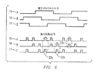
図6に、負の相回転のTRIAC駆動出力を示す。モータコントローラ(4)は、A相線間電圧ゼロクロス(15)のターンオン時間中に、A相電力制御装置出力(14)とC相電力制御装置出力(14)を、楕円(22c)で示すように一緒に駆動する。同様に、モータコントローラ(4)は、B相線間電圧ゼロクロス(16)のターンオン時間中に、B相電力制御装置出力(16)とA相電力制御装置出力(14)を、楕円(22a)で示すように一緒に駆動する。最後に、モータコントローラは、C相線間電圧ゼロクロス(17)のターンオン時間中に、C相電力制御装置出力(14)とB相電力制御装置出力(14)を、楕円(22b)で示すように一緒に駆動する。 FIG. 6 shows the TRIAC drive output of the negative phase rotation. The motor controller (4) indicates that the A phase power controller output (14) and the C phase power controller output (14) are indicated by an ellipse (22c) during the turn-on time of the A phase line voltage zero cross (15). Drive together. Similarly, during the turn-on time of the B phase line voltage zero cross (16), the motor controller (4) converts the B phase power control device output (16) and the A phase power control device output (14) into an ellipse (22a). Drive together as shown. Finally, the motor controller indicates the C-phase power controller output (14) and the B-phase power controller output (14) as an ellipse (22b) during the turn-on time of the C-phase line voltage zero cross (17). Drive together.
図7に、ウィンドウコンパレータのブロック図を示す。DSPベースのモータコントローラは、ウィンドウコンパレータ(88)を用いて、電流波形の正の半分と負の半分の双方のゼロ-クロスを検知する。RMSモータ電圧がモータコントローラによって下げられた場合、電流波形のゼロクロスを検知することは難しい。というのも、電流は、双方の半サイクルのほとんどの部分についてゼロであるからである。先ず、モータ電流が供給され(89)、正の電圧が基準として、正の半サイクル用に供給され(90)、基準として負の電圧が供給される(91)。次に、電流、正の電圧及び負の電圧は、2つのコンパレータ(92)へ与えられて、その後、オペレーション(OR)ゲート(93)を通され、コンポジットゼロ-クロスデジタル信号(94)が生じる。 FIG. 7 shows a block diagram of the window comparator. The DSP-based motor controller uses a window comparator (88) to detect both the positive and negative half-crossings of the current waveform. When the RMS motor voltage is lowered by the motor controller, it is difficult to detect the zero crossing of the current waveform. This is because the current is zero for most parts of both half cycles. First, a motor current is supplied (89), a positive voltage is supplied as a reference for the positive half cycle (90), and a negative voltage is supplied as a reference (91). The current, positive voltage and negative voltage are then applied to two comparators (92) and then passed through an operation (OR) gate (93) to produce a composite zero-cross digital signal (94). .
更に、図8に、ウィンドウコンパレータ(88)の回路図を示す。モータ電流が供給され(89)、正の電圧が基準として、正の半サイクル用に供給され(90)、負の電圧が基準として供給される(91)。次に、正の電圧及び負の電圧として表される電流は、2つのコンパレータ(92)により処理され、その後、ORゲート(93)に渡されて、コンポジットゼロ-クロスデジタル信号(94)が生じる。 Further, FIG. 8 shows a circuit diagram of the window comparator (88). Motor current is supplied (89), positive voltage is supplied as a reference, positive half cycle is supplied (90), and negative voltage is supplied as reference (91). The current, expressed as a positive voltage and a negative voltage, is then processed by two comparators (92) and then passed to an OR gate (93) to produce a composite zero-cross digital signal (94). .
更に、図9に、電流波形(95)、正の電圧半サイクル(96)、負の電圧半サイクル(97)及びORファンクション(98)のグラフを示す。 Further, FIG. 9 shows a graph of a current waveform (95), a positive voltage half cycle (96), a negative voltage half cycle (97), and an OR function (98).
図10に、仮想中性点回路図を示す。仮想中性点回路は、三相電力がデルタモードでのみ使用でき、基準として使用するための中性点(neutral)がない状況で基準として使用され得る。仮想中性点回路は、3つの差動-シングルエンド(three differential-to-single-ended)増幅器(77)を備える。相間電圧が高いため、フィードバック抵抗器(80)及びグランド基準抵抗器(81)と共に入力抵抗器(78)が使用され、適切な減衰器(79)を形成する。欠相(loss of phase)の危険があるため、保護ダイオード(82)が使用されて、差動-シングルエンド増幅器(77)を保護する。差動-シングルエンド増幅器(77)は、DC阻止コンデンサ(84)、サミング抵抗器(85)、フィードバック抵抗器(80)を通って、サミングアンプ(83)に連結される。サミングアンプ(83)の出力は、アンプ(27)でブーストされており、これによって、中性点電位にある低インピーダンス出力を供給する。追加の抵抗器がサプライレール(supply rail)を分割するので、サミングアンプ(83)は、交互の正及び負の信号を処理することができる。代替の中性点接続用のジャンパーブロック(87)と共に中性点(86)が利用できる場合には、代替接続が利用できる。 FIG. 10 shows a virtual neutral point circuit diagram. A virtual neutral point circuit can be used as a reference in situations where three-phase power can only be used in delta mode and there is no neutral point to use as a reference. The virtual neutral circuit comprises three differential-to-single-ended amplifiers (77). Due to the high phase voltage, the input resistor (78) is used with the feedback resistor (80) and the ground reference resistor (81) to form a suitable attenuator (79). Due to the risk of loss of phase, a protection diode (82) is used to protect the differential-single-ended amplifier (77). The differential-single-ended amplifier (77) is connected to the summing amplifier (83) through the DC blocking capacitor (84), the summing resistor (85), and the feedback resistor (80). The output of the summing amplifier (83) is boosted by the amplifier (27), thereby providing a low impedance output at neutral point potential. An additional resistor divides the supply rail so that the summing amplifier (83) can process alternating positive and negative signals. If the neutral point (86) can be used together with the jumper block (87) for an alternative neutral point connection, an alternative connection can be used.
図11に、単相用途について電力制御装置出力(14)を示す。A相の出力(14)は、電圧ゼロ-クロス入力(15)から導かれた電力制御装置出力(14)に基づいて、各半サイクルでオンされる。B相線間電圧ゼロクロス及びC相線間電圧ゼロクロスの電力制御装置出力(14)は、DSP(1)で無効であり、そのハードウェアは無くてもよい。電力制御装置出力(14)は、三相の場合のように対にはならない。 FIG. 11 shows the power controller output (14) for a single phase application. The A phase output (14) is turned on in each half cycle based on the power controller output (14) derived from the voltage zero-cross input (15). The power control device output (14) of the B phase line voltage zero cross and the C phase line voltage zero cross is invalid in the DSP (1), and its hardware may be omitted. The power controller outputs (14) are not paired as in the three-phase case.
図12に、Y軸の監視位相角(5)で境界付けされるモータの動作空間(operating space)について、3次元制御ラインを図示する。電圧の低下を示す制御点弧角/デューティサイクル(23)がX軸に示され、モータのパーセント負荷(24)がZ軸に示されている。 FIG. 12 illustrates a three-dimensional control line for the operating space of the motor bounded by the Y axis monitoring phase angle (5). The control firing angle / duty cycle (23) indicating the voltage drop is shown on the X-axis and the motor percent load (24) is shown on the Z-axis.
全てのモータは、動作空間内のパラメトリック制御ライン(25)に沿って動作する。例えば、モータが50%の負荷で、点弧角/デューティサイクル(23)が100度に設定される場合、約55度の位相角(5)が監視される。 All motors operate along a parametric control line (25) in the operating space. For example, if the motor is at 50% load and the firing angle / duty cycle (23) is set to 100 degrees, a phase angle (5) of about 55 degrees is monitored.
図12に示されるパラメトリック制御ライン(25)は、5つのパラメトリック動作点(parametric operating point)(26)により定義される。5つのパラメトリック動作点は、左上隅の負荷がかかった状況(44)から、右下隅の無負荷の状況(45)に及ぶ。更に、パラメトリック制御ライン(25)は、特別な意味を有する。というのも、モータができるだけ最小のエネルギーを使用している線であるからである。点弧角/デューティサイクル(23)が増大し、モータ電圧(13)が低下するならば、モータは減速し、ストール(stall)するかも知れない。同様な結果は、モータ(3)への負荷が増えると、みられるであろう。 The parametric control line (25) shown in FIG. 12 is defined by five parametric operating points (26). The five parametric operating points range from the loaded condition in the upper left corner (44) to the unloaded condition in the lower right corner (45). Furthermore, the parametric control line (25) has a special meaning. This is because the motor is the wire that uses the least energy possible. If the firing angle / duty cycle (23) increases and the motor voltage (13) decreases, the motor may slow down and stall. Similar results will be seen as the load on the motor (3) increases.
図13に図示するように、パラメトリック制御ライン(25)はパラメータで表されて、垂直方向の位相角(5)と、水平方向の点弧角/デューティサイクル(23)とで示される1平面上に投影され得る。
As shown in FIG. 13, the
更に、図14に示すように、パラメトリック制御ライン(25)は、2次元グラフに表示され得る。X軸上での点弧角/デューティサイクル(23)の増大は、モータ電圧の低下とみなされてよい。これは、小さな点弧角/デューティサイクルは高電圧をもたらし、大きな点弧角/デューティサイクルは低電圧をもたらすからである。モータコントローラは、監視位相角(5)を、モータの現在の負荷に対応した制御ライン(25)上の点へ駆動する。これを達成するために、DSPは、電圧と電流との間の位相角(5)を計算する。
Furthermore, as shown in FIG. 14, the
図2のブロック図に戻ってこれを参照すると、DSP(1)は、RMS電圧(13)の現在値、即ち点弧角/デューティサイクルの現在値に基づいて、次の目標位相角(5)を計算する。監視位相角と目標位相角(10)との差が位相角誤差をもたらし、この誤差が、PIDコントローラ(12)又は類似の装置によって処理されて、新たな制御目標が生成される。この制御目標は、位相角誤差を最小にするような方法で電圧を変える。目標位相角(10)は動的であり、点弧角/デューティサイクルの関数として変化する。 Referring back to the block diagram of FIG. 2, the DSP (1) determines the next target phase angle (5) based on the current value of the RMS voltage (13), that is, the current value of the firing angle / duty cycle. Calculate The difference between the monitored phase angle and the target phase angle (10) results in a phase angle error, which is processed by the PID controller (12) or similar device to generate a new control target. This control target changes the voltage in such a way as to minimize the phase angle error. The target phase angle (10) is dynamic and varies as a function of firing angle / duty cycle.
上述したように、モータコントローラ(4)は、監視位相角(5)を、モータ(3)の現在の負荷に対応した制御ライン(25)上の点に導く。この動作点(26)は、できるだけ最大のエネルギー節約をもたらす。というのも、制御ライン(25)は、制御されているモータ(3)から直接計算較正されるからである。 As described above, the motor controller (4) guides the monitoring phase angle (5) to a point on the control line (25) corresponding to the current load of the motor (3). This operating point (26) provides the greatest possible energy savings. This is because the control line (25) is calculated and calibrated directly from the motor (3) being controlled.
この較正方法は、半自動較正と呼ばれる。半自動較正は、DSP(1)がモータの制御空間をスイープする(sweep)ことに基づいている。図15に示すように、制御空間をスイープすることは、DSPが点弧角/デューティサイクル(23)を増加させて、電流(9)及び各相の点弧角/デューティサイクル(23)を、道に沿って離散した点にて記録することを意味する。従って、このようにして、モータのストール点(stall point)(21)の始まりを見ることができる。制御空間(7)をスイープすることで、監視較正データ曲線のはっきりとした直線部分が得られる。当該直線部分は、制御ライン(6)上の点を決定するために使用され、点弧角/デューティサイクル(23)がより低いところで一定の負の傾きを有する。点弧角/デューティサイクル(23)が増え続けるにつれ、電流(9)は横ばいになり(flatten out)始め、モータ(3)がスリップし始め、そしてストールし始めると、実際に増加し始める。これは「屈曲点(Knee)」(31)と呼ばれる。 This calibration method is called semi-automatic calibration. Semi-automatic calibration is based on the DSP (1) sweeping the motor control space. As shown in FIG. 15, sweeping the control space means that the DSP increases the firing angle / duty cycle (23) and the current (9) and the firing angle / duty cycle (23) of each phase, This means recording at discrete points along the road. Thus, in this way, the beginning of the motor stall point (21) can be seen. By sweeping the control space (7), a clear linear portion of the monitored calibration data curve is obtained. The straight line portion is used to determine a point on the control line (6) and has a constant negative slope where the firing angle / duty cycle (23) is lower. As the firing angle / duty cycle (23) continues to increase, the current (9) begins to flatten out, and begins to increase as the motor (3) begins to slip and then starts to stall. This is called the “knee” (31).
図16に示すように、次のスイープは、モータ電圧のより狭い範囲に向けられて、屈曲点を「ズームイン(zoom in)」することができる。モータコントローラ(4)は、統計的に正確なデータを得るために、複数回のスイープを必要とする。スイープの回数と制御ライン(25)の較正に要求される時間との間にはトレードオフがある。較正の質の度合いは、周知の統計プロセスを用いてDSP(1)によって維持することができ、必要に応じて、スイープを追加することができる。これは、DSP(1)は、最初のスイープにより、屈曲点(31)のおおよその位置を知っているので事実である。 As shown in FIG. 16, the next sweep can be directed to a narrower range of motor voltages to “zoom in” the inflection point. The motor controller (4) requires multiple sweeps to obtain statistically accurate data. There is a trade-off between the number of sweeps and the time required to calibrate the control line (25). The degree of calibration quality can be maintained by the DSP (1) using well-known statistical processes, and sweeps can be added as needed. This is true because the DSP (1) knows the approximate position of the inflection point (31) by the first sweep.
半自動スイープの間、ストールの危険性はほとんどない。というのも、セットアップ環境が制御されているためである。技術者又は操作者は、半自動較正の進行中、試験下のモータ(3)に負荷が突然にかからないようにする。 There is little risk of stalling during the semi-automatic sweep. This is because the setup environment is controlled. The technician or operator ensures that the motor (3) under test is not suddenly loaded during the semi-automatic calibration.
制御空間をスイープするプロセスは、任意の一定負荷時に実行され得る。例えば、一旦モータ(3)に最大の負荷がかかっても、一旦モータ(3)が無負荷となっても、実行され得る。これらの2点は、制御ライン(25)を規定する2点となる。これらの2点において較正を実行する必要はない。DSP(1)は、必要に応じて、これらの2点を超えて制御ライン(25)を延ばす。 The process of sweeping the control space can be performed at any constant load. For example, even if the maximum load is once applied to the motor (3), it can be executed even if the motor (3) is once unloaded. These two points are the two points that define the control line (25). There is no need to perform calibration at these two points. The DSP (1) extends the control line (25) beyond these two points as necessary.
多くの数値法があり、電流モータ電圧(23)のプロット中にストール点(21)を見つけるために適用することができる。図17に示すように、「最小二乗」法を用いて、最初の5つのモータ電圧(23)から表にされた蓄積データに最もフィットする直線が計算される。 There are many numerical methods that can be applied to find the stall point (21) in the plot of the current motor voltage (23). As shown in FIG. 17, using the “least squares” method, the straight line that best fits the stored data tabulated from the first five motor voltages (23) is calculated.
この方法の続きを図18に示す。先のデータ点を用いることで、電流(9)の値を予測できる。図では、DSP(1)は、予測された直線から正の方向に逸れた1又は複数の点をチェックしている。 The continuation of this method is shown in FIG. By using the previous data point, the value of current (9) can be predicted. In the figure, DSP (1) is checking one or more points that deviate in the positive direction from the predicted straight line.
図19に示すように、DSP(1)は、曲線の屈曲点の始まりを探している。予測される制御ラインから逸れる最初の点は、屈曲点(31)の始まりであるかもしれないし、そうではないかもしれない。最初の点が正の誤差であるなら、それは単にノイズのデータ点であり得る。制御空間(7)をスイープして得られた監視較正データ曲線が向きを変えている(turning)ことを確認する唯一の方法は、スイープを追加して得られたデータを監視することである。 As shown in FIG. 19, the DSP (1) is searching for the beginning of the inflection point of the curve. The first point that deviates from the expected control line may or may not be the beginning of the inflection point (31). If the first point is a positive error, it can simply be a noise data point. The only way to verify that the monitoring calibration data curve obtained by sweeping the control space (7) is turning is to monitor the data obtained by adding the sweep.
半自動較正がフィールド(field)で実行されてよい。図20を参照して、どのように半自動較正が実行されるかを示すフローチャートを示す。先ず、モータ(3)は、重い負荷のかかる設定に置かれる(44)。この設定は、最大定格負荷(fully rated load)の50%よりも大きいことが理想である。次に、モータコントローラ(4)の較正ボタン(32)が押されて、DSP(1)に最大負荷測定を実行するように命令する。DSP(1)は、較正を実行する(46)。モータ(3)の動作空間を調べて最大負荷点を決定するためには数秒を要する。モータコントローラ(4)は、LEDを光らせることによってこのステップが終了したことを示す。 Semi-automatic calibration may be performed in the field. Referring to FIG. 20, a flowchart illustrating how semi-automatic calibration is performed is shown. First, the motor (3) is placed in a heavy load setting (44). Ideally, this setting is greater than 50% of the fully rated load. Next, the calibration button (32) of the motor controller (4) is pressed to instruct the DSP (1) to perform a maximum load measurement. The DSP (1) performs calibration (46). It takes several seconds to determine the maximum load point by examining the operating space of the motor (3). The motor controller (4) indicates that this step is completed by illuminating the LED.
次に、モータ(3)は、無負荷の設定に置かれる(45)。この設定は、定格負荷の25%よりも小さいことが理想である。それからモータコントローラ(4)の較正ボタン(32)が押されて(47)、DSP(1)に無負荷測定を実行するように命令する。DSP(1)は、較正を実行して(46)、無負荷点を決定する。モータコントローラ(4)は、発光ダイオード(LED)を光らせることによって、制御ライン(25)の両端の較正(47)が終了したことを示す。DSP(1)は、2つの測定を用いて制御ラインを決定し(48)、モータ(3)を管理する場合に、この制御ラインを利用する。制御ライン(25)の値は、不揮発性メモリに記憶される(49)。 The motor (3) is then placed in a no-load setting (45). Ideally, this setting should be less than 25% of the rated load. Then, the calibration button (32) of the motor controller (4) is pressed (47) to instruct the DSP (1) to perform no-load measurement. The DSP (1) performs calibration (46) to determine the no-load point. The motor controller (4) indicates that the calibration (47) at both ends of the control line (25) has been completed by illuminating the light emitting diode (LED). The DSP (1) determines a control line using two measurements (48), and uses this control line when managing the motor (3). The value of the control line (25) is stored in the non-volatile memory (49).
図21は、半自動較正のより詳細なフローチャートを示す。先ず、第1較正スイープが最初のスイープであるのか、それとも以前にスイープが実行されたのかに応じて(106)、モータ電圧をある角度に設定して(51)、第1較正スイープが実行される(46)。そして、モータコントローラは、屈曲点を検知する(53)までモータを測定する(52)。屈曲点が検知された場合(53)、点弧角/デューティサイクルは2度ずつ減らされ(54)、位相角及びモータ電圧はメモリへ記録される(55)。このプロセスは、位相角及び点弧角/デューティサイクルの計算平均値を得るために(57)、少なくとも4回のスイープを得るように繰り返される(56)。計算スイープに沿う任意のステップ中、屈曲点が検知されなかった場合、点弧角/デューティサイクルは少なくとも1度ずつ増やされ(58)、次のステップが測定される(59)。 FIG. 21 shows a more detailed flowchart of the semi-automatic calibration. First, depending on whether the first calibration sweep is the first or a previous sweep (106), the motor voltage is set to an angle (51) and the first calibration sweep is performed. (46). Then, the motor controller measures the motor (52) until it detects the bending point (53). If an inflection point is detected (53), the firing angle / duty cycle is decreased by 2 degrees (54), and the phase angle and motor voltage are recorded in memory (55). This process is repeated to obtain at least four sweeps (56) to obtain a calculated average of phase angle and firing angle / duty cycle (57). If an inflection point is not detected during any step along the calculated sweep, the firing angle / duty cycle is increased by at least one degree (58) and the next step is measured (59).
較正のための代わりの方法は、手動較正と呼ばれる。図22は手動較正のフローチャートを示す。先ず、モータがダイナモメータに置かれる(70)。次に、モータは手動制御のためのコンピュータに接続され(71)、当該コンピュータにより、モータを開ループモードで駆動し、AC誘導モータの点弧角/デューティサイクルを、任意の動作点(operating point)に手動で設定できる。その後、モータは、完全な無負荷設定に置かれる(45)。次に、モータがまさにストールしようとするまで、点弧角/デューティサイクルが大きくされ、RMSモータ電圧は下がる(72)。点弧角/デューティサイクル及び位相角は記録され、これが記録較正点となる(73)。その後、モータは、ドライブ要素が完全な状態で開始される(74)。そして、モータは最大の負荷設定に置かれる(44)。次に、モータがまさにストールしようとするまでモータコントローラによりRMSモータ電圧がチョップされるまで、点弧角/デューティサイクルは増えるか減る(75)。点弧角/デューティサイクルは記録され、これが、別の記録較正点となる(73)。最後に、その2つの測定点を用いて制御ラインが形成される(76)。 An alternative method for calibration is called manual calibration. FIG. 22 shows a flowchart for manual calibration. First, the motor is placed on the dynamometer (70). The motor is then connected to a computer for manual control (71), which drives the motor in an open loop mode and sets the firing angle / duty cycle of the AC induction motor at any operating point. ) Can be set manually. The motor is then placed in a full no-load setting (45). The firing angle / duty cycle is then increased and the RMS motor voltage is lowered (72) until the motor is about to stall. The firing angle / duty cycle and phase angle are recorded, which becomes the recorded calibration point (73). Thereafter, the motor is started with the drive elements intact (74). The motor is then placed at the maximum load setting (44). The firing angle / duty cycle is then increased or decreased until the RMS motor voltage is chopped by the motor controller until the motor is about to stall (75). The firing angle / duty cycle is recorded, which becomes another recorded calibration point (73). Finally, a control line is formed using the two measurement points (76).
プログラムされた一定電圧よりもRMS線間電圧が大きい場合、DSPコントローラは、その一定電圧でRMSモータ電圧をクランプするので、エネルギー節約は最大負荷時でさえも可能である。例えば、単相モータの場合において、115Vであるモータの銘板の電圧を電源電圧が超える場合、モータ電圧は115Vでクランプされる。モータ電圧をクランプするこの操作によって、モータが単相又は三相の用途において最大に負荷がかかった場合でさえ、モータコントローラはエネルギーを節約できる。 If the RMS line voltage is greater than the programmed constant voltage, the DSP controller clamps the RMS motor voltage at that constant voltage, so energy saving is possible even at full load. For example, in the case of a single phase motor, if the power supply voltage exceeds the voltage on the nameplate of the motor which is 115V, the motor voltage is clamped at 115V. This operation of clamping the motor voltage allows the motor controller to save energy even when the motor is fully loaded in single-phase or three-phase applications.
図23は、一定電圧クランプのフローチャートを示す。先ず、位相誤差が計算される(64)。次に、電圧誤差が計算される(65)。それから、AC誘導モータのRMSモータ電圧が決定され、一定電圧閾値と比較される(66)。RMSモータ電圧が一定電圧閾値よりも大きい場合、制御目標がポジティブであるか否かが決定される(67)。制御目標がポジティブである場合、電圧制御ループが実行される(68)。AC誘導モータのRMSモータ電圧が一定電圧閾値よりも小さい場合、制御ライン閉ループが実行され(69)、全プロセスが繰り返される。制御目標がポジティブでないと決定された場合、制御ラインループが実行され(69)、全プロセスが再度繰り返される。 FIG. 23 shows a flowchart of constant voltage clamping. First, a phase error is calculated (64). Next, the voltage error is calculated (65). The RMS motor voltage of the AC induction motor is then determined and compared to a constant voltage threshold (66). If the RMS motor voltage is greater than a certain voltage threshold, it is determined whether the control target is positive (67). If the control target is positive, a voltage control loop is executed (68). If the RMS motor voltage of the AC induction motor is less than a constant voltage threshold, a control line closed loop is executed (69) and the entire process is repeated. If it is determined that the control target is not positive, a control line loop is executed (69) and the entire process is repeated again.
幾つかの場合において、較正プロセス中にモータ(3)に最大の負荷をかけることができないことがあり得る。モータが、フィールドに設置される間において達成可能な最大負荷は約50%である。反対に、モータを完全に無負荷にすることができないこともあり得る。達成可能な最小負荷が、軽くても40%であることもあり得る。 In some cases, it may not be possible to put maximum load on the motor (3) during the calibration process. The maximum load achievable while the motor is installed in the field is about 50%. Conversely, the motor may not be completely unloaded. The minimum achievable load can be as low as 40%.
図24は、両負荷点が動作範囲の中央付近にある例である。制御ライン(25)の右の無負荷端(45)上で、DSP(1)は、電圧の一定電圧クランプ(60)を最小電圧(35)に設定する。モータへの負荷が増すと、DSP(1)は、制御ラインに従って、制御セグメント(61)まで、左に向けて移動する。この実施は保守的なアプローチであり、較正されていない空間で、モータ(3)が駆動することを防止する。 FIG. 24 shows an example in which both load points are near the center of the operating range. On the right unloaded end (45) of the control line (25), the DSP (1) sets the constant voltage clamp (60) of the voltage to the minimum voltage (35). As the load on the motor increases, the DSP (1) moves to the left along the control line to the control segment (61). This implementation is a conservative approach and prevents the motor (3) from driving in uncalibrated space.
図25に更に示すとおり、左の最大負荷端(44)上で、DSP(1)は、大きな負の傾きのある制御セグメント(61)を合成する。この実施は保守的なアプローチであり、電圧を最大で駆動する。 As further shown in FIG. 25, on the left maximum load end (44), DSP (1) synthesizes a control segment (61) with a large negative slope. This implementation is a conservative approach and drives the voltage at maximum.
図26を参照すると、DSPベースのモータコントローラは、モータがストールするのを防止する特別な手法を用いる。先ず、DSPは、モータへの負荷が増加したことを示す電流(99)の顕著な増加をアクティブに監視する。次に、顕著な増加が確認された場合(100)、DSPは、モータ電圧を最大にする(101)。次に、DSPは、制御へ戻るためにモータ電圧を下げることを試み(102)、DSPは電流の顕著な増加を積極的に監視することに戻る(99)。この技術は、DSPがその時点で知られていない電力要求を探知しようと試みることに代わって、保守的で安全である。 Referring to FIG. 26, the DSP-based motor controller uses a special technique to prevent the motor from stalling. First, the DSP actively monitors a significant increase in current (99) indicating that the load on the motor has increased. Next, if a significant increase is observed (100), the DSP maximizes the motor voltage (101). The DSP then attempts to lower the motor voltage to return to control (102), and the DSP returns to actively monitoring a significant increase in current (99). This technique is conservative and secure instead of the DSP trying to detect a power requirement that is not known at that time.
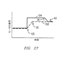
図27に更に示すように、これはストール低減手法のグラフであり、モータへの負荷はX軸に表され、時間はY軸に表される。底の線はモータへの負荷を表し(103)、上の線は、DSPによりモータへ適用される電力を表す(104)。a点(105)より前では、DSPは一定の負荷でモータを動的に制御している。a点(105)とb点(30)の間で、モータへの負荷は突然増え、DSPはモータ電圧を最大にする。c点(34)にて、DSPはモータ電圧をd点(43)にまで下げる。 As further shown in FIG. 27, this is a graph of the stall reduction technique, where the load on the motor is represented on the X axis and the time is represented on the Y axis. The bottom line represents the load on the motor (103) and the top line represents the power applied to the motor by the DSP (104). Before the point a (105), the DSP dynamically controls the motor with a constant load. Between point a (105) and point b (30), the load on the motor suddenly increases and the DSP maximizes the motor voltage. At point c (34), the DSP lowers the motor voltage to point d (43).
図28において、ポンプジャック(30')は、井戸W付近の地上に配置されている。原動機、即ちモータ(6')は、ギア機構、即ちトランスミッション(8')を駆動ベルト(18')で駆動する。モータ(6')は、電力供給用の送電網と接続されてよい。カウンターウェイトアーム、即ちクランクアーム(10')の一端がギア機構(8')に配置されており、カウンターウェイトアーム(10')の他端は、カウンターウェイト、即ち回転質量(12')に配置されている。2本のカウンターウェイトアーム(10')が存在することが好ましく、その間にカウンターウェイト(12')が配置される。レバー、即ち移動ビーム(2')が、サンプソンポスト、即ちA字形フレーム(14')上で枢転する。ピットマンアーム、即ちビームアーム(16')の一端が、ビーム(2')の一端に回動自在に取り付けられており、ビームアーム(16')の他端は回転質量(12')及びカウンターウェイトアーム(10')の端部に回動自在に取り付けられている。ビーム突出部、即ちヘッド(4')は、井戸W付近にて、ビーム(2')の端部に配置されている。理解できるように、ポンプジャック(30')は、従来の設計を有する。 In FIG. 28, the pump jack (30 ′) is disposed on the ground near the well W. The prime mover, that is, the motor (6 ′) drives the gear mechanism, that is, the transmission (8 ′) by the drive belt (18 ′). The motor (6 ′) may be connected to a power transmission network. One end of the counterweight arm, i.e., the crank arm (10 ') is disposed on the gear mechanism (8'), and the other end of the counterweight arm (10 ') is disposed on the counterweight, i.e., the rotating mass (12') Has been. There are preferably two counterweight arms (10 ′), between which the counterweight (12 ′) is arranged. A lever or moving beam (2 ') pivots on a Sampson post or A-frame (14'). One end of the pitman arm, that is, the beam arm (16 ′) is rotatably attached to one end of the beam (2 ′), and the other end of the beam arm (16 ′) is a rotating mass (12 ′) and a counterweight. It is rotatably attached to the end of the arm (10 '). The beam protrusion, that is, the head (4 ′) is arranged at the end of the beam (2 ′) in the vicinity of the well W. As can be appreciated, the pump jack (30 ') has a conventional design.
ケーブル(20')の一端がビームヘッド(4')に取り付けられており、ケーブル(20')の他端は研磨ロッド、即ちロッド(22')に取り付けられている。ロッド(22')は、略垂直な管の列、つまりサッカーロッド(26')に配置され、サッカーロッド(26')は、抗井内ポンプ(28')に繋がるプロダクションチュービングを通って井戸W内に延在している。管の列は、サッカーロッド、パイプ、管状、又は、他の構成要素を含んでよく、それらは、ポンプジャック、又は他の類似の装置と共に使用されて、井戸から流体をポンプで汲み上げるか持ち上げるのに役立つ。モータ(6')は、水平軸回りにカウンターウェイトアーム(10')の端部を回転させることによってポンプジャック(30')を駆動する。カウンターウェイト(12')が上方に動くにつれ、ビーム(2')がA字形フレーム(14')上にて水平軸回りに枢転し、ビームヘッド(4')を下方に動かす。カウンターウェイト(12')は、その最上位置を通過すると、重力及びその運動量によって下方に自由落下し、ビーム(2')は、A字形フレーム(14')回りに枢転し、ビームヘッド(4')を上方に動かす。ビームヘッド(4')による管の列(26')の押し引きが、抗井内ポンプ(28')においてピストンを動作する。管の列(26')は、井戸W内において略垂直に往復移動する。 One end of the cable (20 ′) is attached to the beam head (4 ′), and the other end of the cable (20 ′) is attached to a polishing rod, that is, the rod (22 ′). The rod (22 ') is arranged in a substantially vertical row of tubes, i.e. the soccer rod (26'), which passes through the production tubing connected to the well pump (28 ') in the well W. It extends to. The row of tubes may include soccer rods, pipes, tubes, or other components that are used with a pump jack or other similar device to pump or lift fluid from a well. To help. The motor (6 ′) drives the pump jack (30 ′) by rotating the end of the counterweight arm (10 ′) around the horizontal axis. As the counterweight (12 ′) moves upward, the beam (2 ′) pivots about the horizontal axis on the A-shaped frame (14 ′) and moves the beam head (4 ′) downward. When the counterweight (12 ′) passes through its uppermost position, it freely falls downward due to gravity and its momentum, and the beam (2 ′) pivots around the A-shaped frame (14 ′) and the beam head (4 Move ') upward. Pushing and pulling the tube row (26 ′) by the beam head (4 ′) operates the piston in the well pump (28 ′). The tube row (26 ′) reciprocates in the well W substantially vertically.
モータ(6')は通常、エネルギー消費モードにある。しかし、モータ(6')は、落下質量(falling masses)(カウンターウェイト(12')、又はロッド若しくは管の列(26')の何れか)が自由落下するときにエネルギー発生モードにあることで、モータ(6')の同期速度(synchronous speed)を超えてモータ(6')を加速させる。速度は、発生電流により制限される。例示的な従来型のポンプジャック(30')が図28に示されているが、様々な従来の設計、Lufkin Mark II設計、ビームバランス設計、及び従来のポータブル設計を含む、これらに限られない全てのポンプジャック設計が、本発明の実施形態に用いることができると考えられる。実施形態にはポンプジャックが示されるが、全ての実施形態は、回転質量又は往復質量を有するあらゆる装置に用いられると考えられる。 The motor (6 ′) is normally in energy consumption mode. However, the motor (6 ′) is in energy generation mode when the falling masses (either counterweight (12 ′) or rod or tube row (26 ′)) fall free. The motor (6 ′) is accelerated beyond the synchronous speed of the motor (6 ′). The speed is limited by the generated current. An exemplary conventional pump jack (30 ′) is shown in FIG. 28, including but not limited to various conventional designs, Lufkin Mark II designs, beam balance designs, and conventional portable designs. It is contemplated that all pump jack designs can be used with embodiments of the present invention. Although the embodiment shows a pump jack, all embodiments are contemplated for use with any device having a rotating mass or a reciprocating mass.
図29を参照すると、開ループモードにあって、図28のモータ(6')及びポンプジャック(30')のようなポンプジャックに取り付けられた電気モータについて、監視位相角が垂直軸(32')であり、時間が水平軸(34')であるプロット(36')が示されている。図30乃至図32Dにより以下に記載される本発明の実施形態は、電気モータに取り付けられていない。従って、モータは、開ループモードである。第2水平線(40')が、垂直軸(32')上の90度の監視位相角に引かれている。プロット(36')が、90度の監視位相角を超える第2水平線(40')よりも上のプロットの第1セグメント(42')にある場合、モータは、エネルギー発生モードにある。モータがエネルギーを消費するのではなく発生している場合、電流は、90度を超える位相角分、電圧に遅れている。発生中の位相角が大きくなる程、発生する電力は大きくなる。モータは、第1水平線(38')よりも下のプロット第2セグメント(44')において激しいエネルギー消費モードにある。第1水平線(38')は、垂直軸(32')上の90度未満の目標位相角に引かれている。目標位相角は、以下にて、図30及び図31を参照して詳細に議論される。 Referring to FIG. 29, for an electric motor attached to a pump jack such as the motor (6 ′) and pump jack (30 ′) of FIG. ) And a plot (36 ′) with time on the horizontal axis (34 ′) is shown. The embodiment of the invention described below with reference to FIGS. 30 to 32D is not attached to an electric motor. Therefore, the motor is in an open loop mode. A second horizontal line (40 ') is drawn at a monitoring phase angle of 90 degrees on the vertical axis (32'). If the plot (36 ') is in the first segment (42') of the plot above the second horizon (40 ') above the 90 degree monitoring phase angle, the motor is in energy generation mode. If the motor is generating rather than consuming energy, the current is behind the voltage by a phase angle greater than 90 degrees. The greater the phase angle being generated, the greater the generated power. The motor is in an intense energy consumption mode in the plot second segment (44 ') below the first horizon (38'). The first horizontal line (38 ') is drawn to a target phase angle of less than 90 degrees on the vertical axis (32'). The target phase angle is discussed in detail below with reference to FIGS.
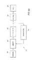
図30において、閉ループモータコントローラ(50')が模式的に示されている。閉ループモータコントローラ(50')は、図28のモータ(6')のような電気モータ(62')と接続されており、このモータ(62')は、図28のポンプジャック(30')のようなポンプジャックと接続され得る。他のポンプジャック設計を、図30に用いることもあり得る。モータコントローラ(50')はPIDコントローラであってよい。しかし、他の閉ループモータコントローラもあり得る。図1及び図2のデジタル信号プロセッサ(DSP)ベースのモータコントローラのような、DSPベースのモータコントローラがあり得る。しかし、他のタイプのDSPベースのモータコントローラもあり得る。閉ループモータコントローラ(50')は、図1及び図2に示すのと同じやり方で、モータ(6',62')と接続され得る。マイクロプロセッサベースコントローラも考えられる。ある実施形態では、閉ループコントローラシステムは、構成要素としてPIDコントローラを有してよい。閉ループコントローラシステム又はサーボシステム(48')において、コントローラ(50')は、モータ(62')に供給される電圧及び電流から監視位相角を計算し得る(52')。 In FIG. 30, a closed loop motor controller (50 ′) is schematically shown. The closed loop motor controller (50 ′) is connected to an electric motor (62 ′) such as the motor (6 ′) of FIG. 28, and this motor (62 ′) is connected to the pump jack (30 ′) of FIG. Such a pump jack can be connected. Other pump jack designs may be used for FIG. The motor controller (50 ′) may be a PID controller. However, there may be other closed loop motor controllers. There may be a DSP based motor controller, such as the digital signal processor (DSP) based motor controller of FIGS. However, there can be other types of DSP-based motor controllers. The closed loop motor controller (50 ′) can be connected to the motors (6 ′, 62 ′) in the same manner as shown in FIGS. A microprocessor-based controller is also conceivable. In some embodiments, the closed loop controller system may have a PID controller as a component. In a closed loop controller system or servo system (48 '), the controller (50') may calculate a monitoring phase angle from the voltage and current supplied to the motor (62 ') (52').
モータ(6',62')、ポンプジャック(30')又は抗井内ポンプ(28')に、センサが配置される必要がないのが有利である。更に、閉ループシステム(48')は、個々の抗井内ポンプ(28')毎に、そして、時間と共に変化するポンプ(28')及び井戸Wのパラメータ及び要求に適応し得る。変化するパラメータ及び要求には、ガス、油、水及びスラリー等の、ポンプで汲み上げられる物質及び/又は流体の、変化する体積、密度、速度、重量、及び他の特性が含まれるが、これらに限られない。システム(48')によって監視される電圧及び電流は、井戸の状態の指標として機能し、変化する井戸パラメータにシステムが適応することを可能にする。電圧及び電流をほぼ連続的に監視することで、井戸の状態をほぼ連続的に読むことができる。ポンプジャックシステムの既存の構成要素が、異なる特性を有する他の構成要素と取り換えられた場合、例えば、管の列を、異なる重量を有する異なる管の列と取り換えたり、又はカウンターウェイトを異なる大きさのカウンターウェイトと取り換えたような場合でも、閉ループシステム(48')は適応できるが、構成要素が置き換えられた後に機械系がリバランスされる(rebalanced)ことが条件となる。機械系のリバランス後に、本発明の実施形態は、エネルギー節約を再開できる。 Advantageously, no sensors need be arranged in the motor (6 ', 62'), pump jack (30 ') or in-well pump (28'). In addition, the closed loop system (48 ') can adapt to individual well pumps (28') and to time-varying pump (28 ') and well W parameters and requirements. Changing parameters and requirements include changing volume, density, speed, weight, and other characteristics of pumped materials and / or fluids, such as gas, oil, water and slurry. Not limited. The voltages and currents monitored by the system (48 ') serve as indicators of well status and allow the system to adapt to changing well parameters. By monitoring the voltage and current almost continuously, the state of the well can be read almost continuously. If an existing component of the pump jack system is replaced with another component with different characteristics, for example, the column of tubes can be replaced with a column of different tubes with different weights or the counterweights can be of different sizes Even when the counterweight is replaced, the closed loop system (48 ′) can be adapted, but the condition is that the mechanical system is rebalanced after the components are replaced. After mechanical system rebalancing, embodiments of the present invention can resume energy savings.
コントローラ(50')に入力された目標位相角(58')が、計算された監視位相角(52')と比較され、誤差(60')即ち2値間の差がコントローラ(50')によって決定され得る。目標位相角(58')は約90度、又は90度を超えるか90度未満であり得ると考えられる。設定時に、使用中のモータにとって最適な結果をもたらす目標位相角(58')が選択され得る。目標位相角(58')は、全モータ負荷について、65度などのように一定であってよいが、他の一定な目標位相角(58')も考えられる。目標位相角(58')はまた、任意の時点におけるモータ負荷の可変関数であってよい。目標位相角(58')の設定は、可能な限り低い目標位相角であってよく、監視可能な十分な電流の流れを常に維持する一方で、全負荷時のモータの要求を満たすのに十分な電力を供給する。 The target phase angle (58 ') input to the controller (50') is compared with the calculated monitoring phase angle (52 '), and the error (60'), that is, the difference between the two values is determined by the controller (50 '). Can be determined. It is contemplated that the target phase angle (58 ′) may be about 90 degrees, or greater than 90 degrees or less than 90 degrees. At the time of setting, a target phase angle (58 ') that gives the best results for the motor in use can be selected. The target phase angle (58 ′) may be constant, such as 65 degrees, for all motor loads, but other constant target phase angles (58 ′) are also conceivable. The target phase angle (58 ′) may also be a variable function of the motor load at any point in time. The target phase angle (58 ') setting may be the lowest possible target phase angle and is sufficient to meet the motor requirements at full load while always maintaining sufficient current flow to be monitored. To supply power.
モータコントローラ(50')は、誤差信号(60')に基づいて、モータ(62')に印加される供給電圧(54')を制御し得る。開ループのエネルギー発生モードの周期中などのように、監視位相角が大きすぎるために誤差(60')が大きい場合には、コントローラ(50')は、監視位相角(52')が目標位相角(58')に下げるように、モータ(62')への供給電圧をより低い値に下げる。激しいエネルギー消費モード中などのように、監視位相角(52')が小さすぎるために誤差(60')が大きい場合には、コントローラ(50')は、監視位相角(52')が目標位相角(58')に移るように、モータ(62')への供給電圧(54')をより高い値に上げる。この閉ループシステム(48')において、電圧及び電流は、モータコントローラ(50')によって継続的に監視及び制御され得る。供給電圧(54')は、図2に示すように、TRIAC、SCR、IGBT又はMOSFETなどの電力制御装置を用いて制御され得ると考えられる。また、コントローラ(50')は、タイマ及びパルス幅変調(PWM)技術を用いて供給電圧を制御する。このことは、図32乃至図32Dを参照して以下で詳細に議論される。また、他の技術も考えられる。 The motor controller (50 ′) may control the supply voltage (54 ′) applied to the motor (62 ′) based on the error signal (60 ′). If the error (60 ') is large because the monitoring phase angle is too large, such as during an open-loop energy generation mode period, the controller (50') indicates that the monitoring phase angle (52 ') is the target phase. The supply voltage to the motor (62 ') is lowered to a lower value so as to lower the angle (58'). If the error (60 ') is large because the monitored phase angle (52') is too small, such as during intense energy consumption mode, the controller (50 ') will monitor the monitored phase angle (52') so that the target phase is The supply voltage (54 ') to the motor (62') is raised to a higher value so as to move to the corner (58 '). In this closed loop system (48 '), the voltage and current can be continuously monitored and controlled by the motor controller (50'). It is believed that the supply voltage (54 ') can be controlled using a power controller such as TRIAC, SCR, IGBT or MOSFET, as shown in FIG. The controller (50 ') controls the supply voltage using a timer and pulse width modulation (PWM) technology. This is discussed in detail below with reference to FIGS. 32 through 32D. Other techniques are also conceivable.
図30に戻って、コントローラ(50')は、モータ(62')における各相の電圧及び電流を読んで、ゼロ-クロス点をキャプチャする。米国特許出願公開第2009/0046490号の図5及び図6は、考えられる電圧ゼロクロス点決定手段のオシログラム及び回路図を夫々提案している。他のタイプの電圧ゼロクロス点決定手段も考えられる。図2に示すように、監視及び/又は制御のために、1又は複数のアナログ-デジタルコンバータを用いて、電圧及び電流がアナログからデジタルへ変換されてよい。コントローラ(50')は、モータ位相角の計算(52')を実行して、監視位相角を与え得る。コントローラ(50')は、監視位相角(52')を目標位相角(58')と比較して、それに応じてモータ供給電圧(54')を制御し得る。位相角は、1又は複数の相において監視され得る。コントローラ(50')は、相回転を自動的に決定するのに用いられ得る。位相サポート手段及び相回転決定手段の考えられる回路図は、米国特許出願公開第2009/0046490号の図7に提案されており、複数相の操作が採用されている。 Returning to FIG. 30, the controller (50 ′) reads the voltage and current of each phase in the motor (62 ′) and captures the zero-cross point. FIGS. 5 and 6 of U.S. Patent Application Publication No. 2009/0046490 propose oscillograms and circuit diagrams, respectively, of possible voltage zero cross point determination means. Other types of voltage zero cross point determination means are also conceivable. As shown in FIG. 2, voltage and current may be converted from analog to digital using one or more analog-to-digital converters for monitoring and / or control. The controller (50 ′) may perform a motor phase angle calculation (52 ′) to provide a monitored phase angle. The controller (50 ′) may compare the monitored phase angle (52 ′) with the target phase angle (58 ′) and control the motor supply voltage (54 ′) accordingly. The phase angle can be monitored in one or more phases. The controller (50 ') can be used to automatically determine the phase rotation. A possible circuit diagram of the phase support means and the phase rotation determining means is proposed in FIG. 7 of US Patent Application Publication No. 2009/0046490, which employs multi-phase operation.
更に、電圧は、相−相間で、又は相-中性点間で監視され得ると考えられる。考えられる仮想中性点回路図を図10に示す。他の仮想中性点回路も考えられる。仮想中性点回路は、3相の電力がデルタモードにおいてのみ利用可能であり、基準として使用するための中性点が存在しない状況において、基準として用いられ得る。ウィンドウコンパレータが、電流波形の正の半分及び負の半分の双方のゼロクロスを検知するのに用いられ得ると考えられる。ウィンドウコンパレータを図7及び図8に示す。他のウィンドウコンパレータも考えられる。米国特許出願公開第2009/0046490号の図8乃至図10は、考えられる半サイクル識別手段の回路図及びオシログラムを夫々提案している。 It is further believed that the voltage can be monitored between phases-phase or between phase-neutral points. A possible virtual neutral point circuit diagram is shown in FIG. Other virtual neutral point circuits are also conceivable. The virtual neutral point circuit can be used as a reference in situations where three-phase power is only available in delta mode and there is no neutral point to use as a reference. It is believed that a window comparator can be used to detect both the positive half and the negative half of the current waveform. The window comparator is shown in FIGS. Other window comparators are also conceivable. Figures 8 to 10 of US 2009/0046490 propose a circuit diagram and an oscillogram, respectively, of possible half-cycle identification means.
図31には、監視位相角が垂直軸(32')で、時間が水平軸(34')であるプロット(64')が、図28のモータ(6')及びポンプジャック(30')のようなポンプジャックに取り付けられる閉ループモードの電気モータについて示されている。図29に示したような、第1水平線(38')の90度に満たない目標位相角がある。図29の場合とは異なり、図31に表された電気モータ出力は、図30に示すようにモータに配置された閉ループシステム(48')からのものである。図31のプロットの第1セグメント(70')では、開ループモードにおいて監視位相角は目標位相角を超えているだろう。しかし、閉ループモードでは、プロットの第1セグメント(70')において、誤差信号(60')は、コントローラ(50')によって、モータへの供給電圧(54')を下げて目標位相角(38')を維持するように、制御の成果をもたらす。開ループモードにおいて監視位相角が90度を超えているであろう場合には、監視位相角の大きな値が、図30の誤差信号(60')の大きな値をもたらす。 FIG. 31 shows a plot (64 ′) in which the monitoring phase angle is the vertical axis (32 ′) and the time is the horizontal axis (34 ′), and the motor (6 ′) and pump jack (30 ′) of FIG. A closed loop mode electric motor attached to such a pump jack is shown. There is a target phase angle less than 90 degrees of the first horizontal line (38 ′) as shown in FIG. Unlike the case of FIG. 29, the electric motor output shown in FIG. 31 is from a closed loop system (48 ′) located in the motor as shown in FIG. In the first segment (70 ′) of the plot of FIG. 31, the monitoring phase angle will exceed the target phase angle in the open loop mode. However, in the closed loop mode, in the first segment (70 ') of the plot, the error signal (60') is reduced by the controller (50 ') by lowering the supply voltage (54') to the motor to the target phase angle (38 '). ) Bring the result of control to maintain. If the monitoring phase angle will be greater than 90 degrees in the open loop mode, a large value of the monitoring phase angle will result in a large value of the error signal (60 ') of FIG.
プロットの第1セグメント(70')の間、モータは、PWM手法を用いて効率的にオフされるが、モータへの電力を実際に切ることはない。この間にもモータを流れる電流があり、これによってコントローラ(50')は、エネルギー消費モード中に必要とされるモータへの供給電圧を何時上げるべきかを知ることができる。電流の実成分は実質的にゼロに下げられ得るが、無効分はゼロを超えたままである。大部分が無効性の電流の流れを、電圧を下げているときに幾らか与えることによって、閉ループ制御システム(48')において負荷状態の指標として用いられる監視可能なフィードバックパラメータが与えられ、それに対してコントローラ(50')が応答して、エネルギー消費段階において必要とされる場合に電力を供給し得る。 During the first segment (70 ') of the plot, the motor is effectively turned off using the PWM approach, but does not actually cut power to the motor. During this time there is also current flowing through the motor, which allows the controller (50 ') to know when to increase the required supply voltage to the motor during the energy consumption mode. The actual component of the current can be substantially reduced to zero, but the reactive component remains above zero. Giving some largely ineffective current flow when reducing the voltage gives a monitorable feedback parameter that is used as an indicator of load conditions in the closed loop control system (48 '), whereas The controller (50 ') can then respond to supply power when needed during the energy consumption phase.
電流が無効性であるため、残りの電力のみが見掛けの性質(apparent nature)である。電流の流れにより、コントローラは、電流と電圧の間の位相角を継続的に監視することができる。図29に示されるような開ループモードにおいては、監視位相角が90度を超える最大値であり得る場合、図31のプロットのほぼ第1場所(66')で、最大のモータ電圧低下が生じる。 Since the current is invalid, only the remaining power is apparent nature. The current flow allows the controller to continuously monitor the phase angle between current and voltage. In the open loop mode as shown in FIG. 29, the maximum motor voltage drop occurs approximately at the first location (66 ′) of the plot of FIG. 31 when the monitored phase angle can be a maximum value exceeding 90 degrees. .
閉ループモードにおいて、監視位相角が目標位相角を超えた場合、供給電圧は、監視位相角が目標位相角に達するまで、PWM手法を用いて下げられてよい。図31のプロットの第1セグメント(70')の開始時に、モータコントローラ(50')は、開ループモードからの監視位相角を目標位相角にまで下げる。その後、コントローラ(50')は、監視位相角をほぼ目標位相角に維持する。監視位相角が目標位相角を下回る更なる低下は、負荷の増大として解釈されて、それに対してコントローラ(50')は、目標位相角に再度達するまで供給電圧(54')を大きくすることで応答し得る。モータへの供給電圧の最大の上昇は、監視位相角が目標位相角よりも下がった場合にプロット第2場所(68')にて生じる。カウンターウェイト又は往復質量がモータによって駆動される場合、監視位相角の値は通常、目標位相角よりも小さいので、コントローラ(50')は、モータへの供給電圧を上げるように制御効果をもたらす誤差信号を発生する。第1水平線(38')よりも下のプロットの第2セグメント(44')において、モータは、激しいエネルギー消費モードにある。 In closed loop mode, if the monitored phase angle exceeds the target phase angle, the supply voltage may be lowered using a PWM technique until the monitored phase angle reaches the target phase angle. At the start of the first segment (70 ′) of the plot of FIG. 31, the motor controller (50 ′) reduces the monitored phase angle from the open loop mode to the target phase angle. Thereafter, the controller (50 ′) maintains the monitored phase angle at approximately the target phase angle. A further decrease in the monitored phase angle below the target phase angle is interpreted as an increase in load, whereas the controller (50 ') increases the supply voltage (54') until the target phase angle is reached again. Can respond. The maximum increase in supply voltage to the motor occurs at plot second location (68 ') when the monitored phase angle falls below the target phase angle. When the counterweight or reciprocating mass is driven by a motor, the value of the monitored phase angle is usually less than the target phase angle, so the controller (50 ') is an error that has a control effect to increase the supply voltage to the motor. Generate a signal. In the second segment (44 ') of the plot below the first horizon (38'), the motor is in a violent energy consumption mode.
図32には、受電線間電圧の波形プロット(200)が単相で図示されているが、三相電圧も考えられる。図32Aでは、PWM手法が用いられて、電圧波形プロットのセグメント(204)をチョップする、又は除く一方、電圧波形プロットのセグメント(202)を残している。図32Aは、供給電圧の激しいチョップを示しており、電圧波形の大きなセグメント(204)がチョップされている。図32Bは、PWM手法による電圧波形の軽いチョップを図示しており、チョップされた電圧波形プロットのセグメント(206)は、図32Aに示されるチョップされたセグメント(204)よりも小さい。図32Bにおける残された波形プロットのセグメント(208)は、図32Aにおける残された波形プロットのセグメント(202)よりも大きい。 In FIG. 32, the waveform plot (200) of the voltage between the receiving lines is shown in a single phase, but a three-phase voltage is also conceivable. In FIG. 32A, a PWM technique is used to chop or remove the voltage waveform plot segment (204) while leaving the voltage waveform plot segment (202). FIG. 32A shows a chop where the supply voltage is intense, with the segment (204) having a large voltage waveform being chopped. FIG. 32B illustrates a light voltage waveform chop by the PWM approach, where the chopped voltage waveform plot segment (206) is smaller than the chopped segment (204) shown in FIG. 32A. The remaining waveform plot segment (208) in FIG. 32B is larger than the remaining waveform plot segment (202) in FIG. 32A.
図32Aの激しいチョップは、図31のプロットの第1場所(66')のような開ループエネルギー発生モードが生じ得る周期中に起こる。図32Dには、激しいチョップ(210A)の周期が、プロットセグメント(210)に図示されている。図32Aに示す電圧の低下は、電流の実成分をほぼゼロに下げるが、無効分をゼロを超えたままとする。この周期では、モータが効率的にオフにされる一方で、電流は、位相角を監視する程十分なままとされる。 The intense chop of FIG. 32A occurs during a period in which an open loop energy generation mode such as the first location (66 ′) of the plot of FIG. 31 can occur. In FIG. 32D, the period of intense chop (210A) is illustrated in plot segment (210). The voltage drop shown in FIG. 32A reduces the real component of the current to nearly zero, but leaves the ineffective portion above zero. In this period, the motor is effectively turned off while the current remains sufficient to monitor the phase angle.
図31のプロットの第2セグメント(44')に生じるような激しいエネルギー消費モードに、モータがある場合、電圧波形のセグメントはほとんど除かれず、モータ供給電圧は、ほとんど図32に示すようになる。図32Dにおいて、チョップがほとんどない周期(212A)がプロットセグメント(212)にて生じる。 If the motor is in the intense energy consumption mode as occurs in the second segment (44 ') of the plot of FIG. 31, the voltage waveform segment is hardly removed and the motor supply voltage is almost as shown in FIG. . In FIG. 32D, a period (212A) with little chop occurs in plot segment (212).
図32Dにおいて、DSPコントローラは、プロット場所(226,228)にて制御モードにある。これらの周期中、モータは、激しいエネルギー消費モードにあるのではなく、また、開ループエネルギー発生モードが生じ得る周期にあるのでもない。制御モードでは、モータ電圧を制御するために、図32Bに示すような軽いチョップ(226A)が起こり得るか、図32Cに示すような可変のチョップが起こり得る。これは、モータが軽く負荷をかけられたときに起こり、エネルギーを節約する一方で、モータはエネルギーを消費している。図32Cにおける可変のチョップは、モータ電圧を制御するために、PWMを用いて大小様々の波形プロットのセグメント(214,216,218,220,222,224)をチョップする。図32Cにおいてチョップされた電圧波形プロットのセグメント(214,216,218,220,222,224)の大きさは全て異なり、電圧波形プロットのセグメントも全て異なる大きさであってよい。 In FIG. 32D, the DSP controller is in control mode at plot locations (226, 228). During these cycles, the motor is not in a violent energy consumption mode, nor is it in a cycle where an open loop energy generation mode can occur. In the control mode, a light chop (226A) as shown in FIG. 32B can occur or a variable chop as shown in FIG. 32C can occur to control the motor voltage. This occurs when the motor is lightly loaded, saving energy while the motor is consuming energy. The variable chop in FIG. 32C chops the segments (214, 216, 218, 220, 222, 224) of large and small waveform plots using PWM to control the motor voltage. The sizes of the chopped voltage waveform plot segments (214, 216, 218, 220, 222, 224) in FIG. 32C are all different, and the voltage waveform plot segments may all be different sizes.
モータコントローラは、軽いチョップ、激しいチョップ、可変なチョップ、又はチョップなし、のあらゆる組合せ又は並べ替え(permutation)を用いて、モータ供給電圧の監視位相角を目標位相角に制御し得ることが理解できるであろう。デジタル信号プロセッサ(DSP)又はモータコントローラは、実質的に一定な監視位相角を維持しようとし、そうするために必要な量をチョップする。DSPは、監視位相角に基づいてモータ電圧を制御する。供給電圧のチョップ量は変化し得る。 It can be understood that the motor controller can control the monitored phase angle of the motor supply voltage to the target phase angle using any combination or permutation of light chop, intense chop, variable chop, or no chop. Will. A digital signal processor (DSP) or motor controller attempts to maintain a substantially constant monitoring phase angle and chops the amount necessary to do so. The DSP controls the motor voltage based on the monitored phase angle. The chop amount of the supply voltage can vary.
開ループで動く電気モータがエネルギー発生モードにある場合、送電網で与えられる負荷は、モータへのブレーキとしての役割を効果的に果たし、これによってその速度を制限する。このことは、送電網で与えられる電圧を発生電圧が超えようとすることで生じ、これによって、電流が反対方向に流れるようにもたらされる。閉ループコントローラシステム及び方法が、図30乃至図32Dに示すように用いられる場合、このブレーキ作用は効果的に最小化されるか、除かれて、モータ及びシステムは通常、この間に加速するであろう。システムに蓄えられるこの付加的な運動エネルギーは、モータでエネルギーを消費することなしに、ポンプ動作の一部を実行するのに用いられる。エネルギー発生の最小化、又は実質的な防止は、ポンプサイクルの他の部分においてエネルギーを消費する必要性を排除して、これによってエネルギーを節約する。 When an electric motor running in an open loop is in the energy generation mode, the load provided by the grid effectively serves as a brake to the motor, thereby limiting its speed. This occurs because the generated voltage tries to exceed the voltage provided by the grid, which causes the current to flow in the opposite direction. If the closed loop controller system and method is used as shown in FIGS. 30-32D, this braking action is effectively minimized or eliminated, and the motor and system will typically accelerate during this time. . This additional kinetic energy stored in the system is used to perform part of the pump operation without consuming energy at the motor. Minimization or substantial prevention of energy generation eliminates the need to consume energy in other parts of the pump cycle, thereby saving energy.
理解できるように、モータに供給される電力は、開ループにおいて生じるであろうエネルギー発生モードの間、「効果的に」オフにされる一方で、電圧及び電流のフィードバック信号を維持して、監視位相角が小さくなる場合に電気モータを何時オンに戻すべきか決定する。このシステム及び方法は、井戸において変化するパラメータに常に適応し、これまでなされ得なかったものである。1つの例として、モータ及びシステムは、異なる密度又は重量を有する2又は3以上の流体をその時々において汲み上げするように適応できる。システムによって監視される電圧及び電流は、井戸の状態の指標として機能し、これによってシステムは、変化する井戸パラメータに適応できる。エネルギー発生モードに入らないことによって、開ループエネルギー発生モードによってもたらされるブレーキ作用は、最小化され得るか除かれ得るので、システムにおいて加速の利点が得られる。別の方法ではシステムによって消費され得るエネルギーを、最小化又は除去することによって、エネルギー節約は、モータへの供給電圧の低下と、発生モード時のモータのブレーキ作用の最小化又は除去との双方に起因してよい。 As can be seen, the power supplied to the motor is "effectively" turned off during the energy generation mode that would occur in an open loop while maintaining voltage and current feedback signals to monitor Determine when to turn the electric motor back on when the phase angle is small. This system and method always adapts to changing parameters in the wells and could not be done before. As one example, the motor and system can be adapted to pump two or more fluids having different densities or weights from time to time. The voltages and currents monitored by the system serve as indicators of well status, which allows the system to adapt to changing well parameters. By not entering the energy generation mode, the braking effect provided by the open loop energy generation mode can be minimized or eliminated, thus providing an acceleration advantage in the system. Alternatively, by minimizing or eliminating the energy that can be consumed by the system, energy savings both reduce the supply voltage to the motor and minimize or eliminate the braking action of the motor during the generation mode. May result.
前述の本発明の異なる実施形態に、全ての種類及び設計の電気モータを用いることが考えられ、AC誘導モータ、及びAC同期モータを含むが、これらに限られない。前述の本発明の異なる実施形態に、全ての種類及び設計のポンプジャックを用いることが考えられ、従来設計であるLufkin Mark II設計、ビームバランス設計、及び従来のポータブル設計の全てを含むが、これらに限られない。実施形態がポンプジャックについて示されているが、前述の全ての実施形態は、回転質量又は往復質量を有するあらゆる装置に用いられ得ると考えられる。一部の実施形態は単相電圧及び電流について示されているが、本発明の全ての実施形態は、単相又は多相の電圧及び電流について考えられる。 It is contemplated that all types and designs of electric motors may be used in the different embodiments of the present invention described above, including but not limited to AC induction motors and AC synchronous motors. The different embodiments of the present invention described above may be considered to use all types and designs of pump jacks, including all of the conventional designs, the Lufkin Mark II design, the beam balance design, and the traditional portable design. Not limited to. Although embodiments are shown for a pump jack, it is contemplated that all of the previous embodiments can be used with any device having a rotating mass or a reciprocating mass. Although some embodiments are shown for single phase voltage and current, all embodiments of the invention are contemplated for single phase or multiphase voltage and current.
図33を参照すると、ターンオフ方法を実施するモータコントローラ(304)の設置の典型例が示されている。モータコントローラ(304)は、既に説明して、図1及び図2に示したように、PIDコントローラベースのDSPであってよいが、既に説明したように、その他の閉ループコントローラでも実施され得る。モータコントローラ(304)は、既存の電気制御パネル(302)と、ポンプジャック(308)を駆動する電気モータ(306)との間に、電気的に接続されて挿入される。電力供給は、需給計器(300)を通って、制御パネル(302)に至る。 Referring to FIG. 33, a typical installation of a motor controller (304) that implements a turn-off method is shown. The motor controller (304) may be a PID controller-based DSP as previously described and illustrated in FIGS. 1 and 2, but may also be implemented with other closed-loop controllers as previously described. The motor controller (304) is electrically connected and inserted between the existing electric control panel (302) and the electric motor (306) that drives the pump jack (308). The power supply reaches the control panel (302) through the utility meter (300).
図34Aは、ポンプジャックを駆動する電気モータから測定された位相角の典型的な時間変化を示している。監視位相角が垂直軸(310)であり、時間が水平軸(明確性のために示さず)であるプロット(314)が、開ループモードでポンプジャックを駆動する電気モータについて示されている。第1水平ライン(312)は、垂直軸(310)上の90度の監視位相角にて引かれている。最初の1ポンプサイクル又はストロークが、最初の時間セグメント(316)の間で生じ、次のポンプサイクル又はストロークが、次の時間セグメント(318)の間で生じ、3番目のポンプサイクル又はストロークが、3番目の時間セグメント(320)の間で起こる。 FIG. 34A shows a typical time variation of the phase angle measured from the electric motor driving the pump jack. A plot (314) where the monitored phase angle is the vertical axis (310) and the time is the horizontal axis (not shown for clarity) is shown for an electric motor driving the pump jack in open loop mode. The first horizontal line (312) is drawn at a monitoring phase angle of 90 degrees on the vertical axis (310). The first pump cycle or stroke occurs during the first time segment (316), the next pump cycle or stroke occurs during the next time segment (318), and the third pump cycle or stroke is Occurs during the third time segment (320).
図34Aに示されるように、典型的なポンプストロークの間、ポンプジャックモータは1回又は2回重い負荷と、1回又は2回軽い負荷とを受ける。ポンプジャックの配置と釣り合いによって、落錘(カウンターウェイト又はロッド列の何れか)は、その同期速度を超えてモータを駆動することができ、それにより、それをジェネレータとして機能させる。その時間の間、位相角は、90度を超える。 As shown in FIG. 34A, during a typical pump stroke, the pump jack motor is subjected to one or two heavy loads and one or two light loads. Depending on the arrangement and balance of the pump jack, the falling weight (either counterweight or rod train) can drive the motor beyond its synchronous speed, thereby making it function as a generator. During that time, the phase angle exceeds 90 degrees.
オン-オフ方法の実行を始めるために、一旦、初期化して、モータコントローラは、位相角を監視して、3つの状態の内の1つで作動してよい。 To begin performing the on-off method, once initialized, the motor controller may monitor the phase angle and operate in one of three states.
方法のステージ1
オン-オフ方法のステージ1において、ポンプジャックによってモータが受ける負荷プロファイルが評価されて、モータをオフする機会があるか否かを決定して、その機会がある場合、ポンプストロークの間における適切なターンオン又はターンオフの時間を特定する。負荷プロファイルは、位相角の変化によって特徴づけられ得る。エネルギー発生時間の間に、モータをオフする場合、モータは加速して、それにより負荷プロファイルを変える。それ故に、この変化を特徴づけることが望ましい。これは、オン―オフプロセスの効果に近い近似として、モータに閉ループPID制御プロセス(「重いチョッピング(heavy chopping)」)を施すことによって実施される。
In
図34Bは、モータへの閉ループPID制御プロセスの効果とその負荷プロファイルを示している。最初のプロットセグメント(322)の間、図34に示すように、モータは、完全な未修正の供給線電圧が供給されて、その期間、位相角が監視される。位相角が、例えば、プロット位置(326)に示された70度といった、所定の閾値を越えていることが観測された場合、モータは、軽い負荷を受けており、エネルギー発生状態に入る寸前であると考えられる。この瞬間は、将来のポンプストロークにおいて、起こり得るターンオフ時間として特定される。閾値を越えると、閉ループPIDコントローラプロセスが駆動し、60度などの一定の目標位相角にて引かれた第2の水平ライン(313)で示されるように、モータ電圧を目標位相角になるように制御する。他の目標位相角も考えられる。目標位相角が、一定ではないこともあり得るが、それはモータの負荷の状態に依存して変化するであろう。 FIG. 34B shows the effect of the closed loop PID control process on the motor and its load profile. During the first plot segment (322), as shown in FIG. 34, the motor is supplied with a complete, unmodified supply line voltage, during which time the phase angle is monitored. If the phase angle is observed to exceed a predetermined threshold, for example 70 degrees indicated at plot position (326), the motor is under light load and is about to enter an energy generating state. It is believed that there is. This moment is identified as a possible turn-off time in a future pump stroke. When the threshold is exceeded, the closed loop PID controller process is driven to bring the motor voltage to the target phase angle as shown by the second horizontal line (313) drawn at a constant target phase angle such as 60 degrees. To control. Other target phase angles are also conceivable. The target phase angle may not be constant, but it will vary depending on the load condition of the motor.
閉ループPID制御プロセスの間、十分な電流が維持されて、閉ループ制御システムに監視可能なフィードバックが提供される。負荷の増加が、プロット位置(328)に示すような特定の閾値以上の供給電圧の増加を伴うまで、閉ループPID制御プロセスは動作状態のままにされる。これは、TRIAC、SCR、IGBT又はMOSFET等のスイッチングデバイスを制御するために用いられる点弧角において、90度のような所定の閾値を下回る低下によって特定されてよい。この瞬間は、将来のポンプストロークの起こり得るターンオン時間として特定される。この閾値点弧角を超えると、プロット配置(330)に示された軽い負荷状態が再び特定されるまで、完全に未修正の線間電圧が、モータへ戻されてよい。 During the closed loop PID control process, sufficient current is maintained to provide observable feedback to the closed loop control system. The closed loop PID control process is left operating until the load increase is accompanied by an increase in supply voltage above a certain threshold as shown in plot position (328). This may be specified by a drop below a predetermined threshold, such as 90 degrees, in the firing angle used to control switching devices such as TRIAC, SCR, IGBT or MOSFET. This moment is identified as a possible turn-on time for a future pump stroke. Beyond this threshold firing angle, a completely uncorrected line voltage may be returned to the motor until the light load condition shown in plot arrangement (330) is again identified.
上記の測定が一貫していることを保証するために、上記のプロセスは、4ストロークなどの数回のポンプストロークが繰り返されてよい。変更されたポンプストロークの期間と、ストローク中の特定されたターンオフ時間及びターンオン時間とが、繰り返されるストロークの間で比較されてよい。監視された幾つかのストロークの全ての測定において、近い又は繰り返しの相関関係が観測された場合、システムは、開ループオン−オフ状態に入るのに適していると考えられ得る。近い相関関係又は基準は、ポンプストロークの期間において200ミリ秒(ms)を超えない変化であると考えられ得る。他の相関又は基準は、ターンオン時間及びターンオフ時間において150msを超えない変化であると考えられ得る。その他の相関又は基準も考えられる。相関要件が満たされない場合は、システムは、ステージ1のままであり、必要とされる相関関係が観測されるまで、閉ループPID制御プロセスが用いられ続ける。
In order to ensure that the above measurements are consistent, the above process may be repeated several pump strokes, such as 4 strokes. The duration of the changed pump stroke and the identified turn-off and turn-on times during the stroke may be compared between repeated strokes. If close or repetitive correlations are observed in all measurements of several monitored strokes, the system may be considered suitable for entering an open loop on-off state. A close correlation or criterion may be considered a change that does not exceed 200 milliseconds (ms) in the duration of the pump stroke. Other correlations or criteria may be considered changes in turn-on and turn-off times that do not exceed 150 ms. Other correlations or criteria are also possible. If the correlation requirement is not met, the system remains in
典型的なポンプジャックのポンプストロークは、通常、モータがオフにされ得る又は2つの期間を有する。これらの2つの期間は、タイミングと存続期間において、夫々が異なるように取り扱われてよい。2つの期間の内の何れか一方又は両方は、オン−オフ状態に入るための基準に一致し得る。シングルポンプストロークにおける軽い負荷又は発生モードの3以上の期間があってよいが、2つの最も長い期間だけが、何らかの意味のあるエネルギー節約を提供すると考えられている。追加の期間は、通常、モータが「ポンプオフ(pumped-off)」状態のときに、短く生じるだけである。最小オフ時間の設定又は必要要件が維持されて、この目標を超える2つのオフ時間の最大値を支持する。より多いオフ時間を支持する実施も考えられる。追加の発生条件が監視される場合、システムは、これらの時間の間、閉ループPIDを作動する。 A typical pump jack pump stroke typically has two periods, or the motor can be turned off. These two periods may be treated differently in timing and duration. Either one or both of the two time periods may meet the criteria for entering the on-off state. Although there may be more than two periods of light load or mode of occurrence in a single pump stroke, only the two longest periods are believed to provide some meaningful energy savings. The additional period usually only occurs briefly when the motor is in a “pumped-off” state. A minimum off-time setting or requirement is maintained to support a maximum of two off-times that exceed this goal. Implementations that support more off-time are also contemplated. If additional occurrence conditions are monitored, the system activates the closed loop PID during these times.
方法のステージ2
オン−オフ状態になると、各ポンプストロークの間、位相角が監視されて、ステージ1の間に予期された時間に、確立されたターンオフ閾値を超えることを確実にしてよい。位相角が(上述したような合理的な所定のマージン内で)予想したタイミングと一致しない場合、そのタイミングは、閉ループPID制御状態の間に確立されているので、負荷プロファイルを変更することが考えられ得る。制御システムは、ステージ1に戻って、その測定が繰り返されてよい。
Once in the on-off state, the phase angle may be monitored during each pump stroke to ensure that the established turn-off threshold is exceeded at the expected time during
予期されたタイミングが満たされる場合、モータに印加された電圧が、図34Cに示されるようにほぼ即時に、且つ完全にオフにされてよい。ステージ1の間に計算された存続期間の間、オフのままにされてよい。プロット場所(324)のように、オン状態に戻った後、ほぼ即時に監視位相角が評価されて、所定の理想位相角値と比較されてよい。この理想位相角は、オン状態に戻った後で、モータが、エネルギーを発生せず、或いは、即座に過度のエネルギーを消費しないことを保証する。この理想とする位相角値は、75度であるが、他の値も考えられる。
If the expected timing is met, the voltage applied to the motor may be turned off almost immediately and completely as shown in FIG. 34C. It may be left off for the duration calculated during
監視された値が、この理想値を超える場合、電圧がより長い間、オフのままにできていたと考えられる。監視された位相角値がこの値よりも小さい場合は、電圧がより早くオンにできていたであろう。オフの存続期間が調節されて、次のストロークにおける動作を最適化してよい。モータに印加された電圧は、次の予期されたオフ時間まで、完全にオンのままにされてよい。オン-オフ状態は、監視できる位相角で表されて、図34Cに示される。供給がオフにされると電流がないので、これらの期間の間に監視できる位相角は存在しない。 If the monitored value exceeds this ideal value, it is likely that the voltage was left off for a longer time. If the monitored phase angle value was less than this value, the voltage would have been able to turn on earlier. The duration of off may be adjusted to optimize operation on the next stroke. The voltage applied to the motor may remain fully on until the next expected off time. The on-off state is represented in FIG. 34C, represented by a phase angle that can be monitored. Since there is no current when the supply is turned off, there is no phase angle that can be monitored during these periods.
方法のステージ3
負荷プロファイルの時間に渡った段階的なドリフト(drift)を許容するために、コントロールシステムは、周期的に、ステージ1に戻り、閉ループPID制御プロセスを再評価してよい。これは、2分毎に行われてよい。他の時間も考慮されてよい。1回のポンプストロークの後で、閉ループPID制御方法において、変化がほとんど発見されないか、全くない場合、時間要件に僅かな調節が行われ、制御システムは、更なるオン-オフストロークのために、ステージ2に戻ってよい。タイミングに大きな変化が発見された場合、上記で説明したように、一致したタイミングパターンが、数回の連続したポンプストロークに渡って発見され得るまで、システムは、閉ループPID制御状態を維持されてよい。
In order to allow a gradual drift over time of the load profile, the control system may periodically return to
図35は、所定の期間において、供給電圧をオフにして、それをオンに戻す方法のステップの要約版である。更なるステップ、又はより少ないステップも考えられる。その他のステップもあり得る。第1ブロック(330)において、システムが初期化されて、ポンプジャックモータの位相角が監視される。ステージ1に対応する第2ブロック(332)において、閉ループPID制御へのモータの応答が、幾つかのポンプストロークに渡って評価される。モータをオフすることが実行可能なポンプストロークの期間が特定される。第3ブロック(334)において、数回のストロークに渡る測定の一貫性が評価される。ステージ2に対応する第4のブロック(336)において、各ポンプストロークが、ステージ1の閉ループPID制御プロセスの間に予期されたほぼ同様の振る舞いを示す場合、モータは、連続するポンプストロークの所定の期間の間に、オフにされる。ステージ3に対応する第5ブロック(338)において、システムの任意の変化を調節する所定期間の後、システムは、ステージ1の閉ループPID制御プロセスに戻る。
FIG. 35 is a summary version of the method steps for turning off the supply voltage and turning it back on for a predetermined period of time. Further steps or fewer steps are also conceivable. There may be other steps. In the first block (330), the system is initialized and the phase angle of the pump jack motor is monitored. In the second block (332) corresponding to stage 1, the motor response to the closed loop PID control is evaluated over several pump strokes. A period of pump strokes that can be performed to turn off the motor is identified. In a third block (334), the consistency of the measurement over several strokes is evaluated. In the fourth block (336) corresponding to stage 2, if each pump stroke exhibits approximately the same behavior expected during the
理解できるように、オン−オフ方法は、監視位相角に基づいてポンプジャックモータの負荷の予期される変化を監視して特徴づける手段を提供する。一旦、負荷が特徴づけられると、方法は、各ストロークの部分の間に、モータをオフすることによって、エネルギーを節約するための機会が存在するかどうかを決定する。この方法は、この機会が連続するポンプストロークの間にていつ起こるべきかを予測して、モータをオフにして、それを再びオンする条件として、連続するポンプストローク内で満たすべき基準を規定する。本システムと方法は、ポンプジャックの振る舞いにおける段階的な変化に順応的に適合するアルゴリズムを実施し、この振る舞いにおける突然の大きな変化を認識して反応するための保護を行う。 As can be appreciated, the on-off method provides a means to monitor and characterize expected changes in pump jack motor load based on the monitored phase angle. Once the load is characterized, the method determines if there is an opportunity to save energy by turning off the motor during each stroke portion. This method predicts when this opportunity should occur between successive pump strokes and defines the criteria to be met within successive pump strokes as a condition to turn off the motor and turn it back on . The system and method implements an algorithm that adaptively adapts to gradual changes in pump jack behavior and provides protection to recognize and react to sudden large changes in this behavior.
本システムと方法は、ポンプジャック用途におけるモータの、負荷の高周期的な変化に有利である。本システムと方法は、モータへの電力が完全にオフにされ得る場合、ポンプストロークの間にてこれらの時間に加えて、電力が再印加される適切な時間を正確に予期する。モータへの電力を完全にオフすることは、より優れたエネルギー節約をもたらすことになる。 The system and method is advantageous for high periodic changes in the load of the motor in pump jack applications. The system and method accurately anticipates the appropriate time that power will be reapplied in addition to these times during the pump stroke, if the power to the motor can be completely turned off. Turning off the power to the motor completely will result in better energy savings.
本システムと方法は、印加電圧と消費電流の間の監視位相角に基づいて、ポンプジャックの負荷の周期的な変化を監視し特徴づける手段を提供する。一旦負荷が特徴づけられると、各ストロークの期間に、モータをオフすることによって、エネルギーを節約する機会が存在するかの決定を行う。本システムと方法は、連続するポンプストロークにおいて、この機会が起こるべき時を予測して、モータをオフして、再びそれをオンする条件として、連続するポンプストロークにおいて満たされるべき基準を決定する。本システムと方法は、ポンプジャックの振る舞いにおける段階的な変化に順応的に適合するアルゴリズムを実施し、この振る舞いにおける突然の大きな変化を認識して反応するための保護を行う。 The system and method provide a means to monitor and characterize periodic changes in pump jack load based on the monitored phase angle between applied voltage and current consumption. Once the load is characterized, a determination is made whether there is an opportunity to save energy by turning off the motor during each stroke. The system and method predict when this opportunity should occur in successive pump strokes and determine the criteria to be met in successive pump strokes as a condition to turn the motor off and on again. The system and method implements an algorithm that adaptively adapts to gradual changes in pump jack behavior and provides protection to recognize and react to sudden large changes in this behavior.
本発明の前述の開示及び記載は、本発明の説明のためのものであり、図示した装置及びシステム、並びに動作の構造及び方法の詳細において、本発明の精神から逸脱しない限り、種々の変更がなされ得る。 The foregoing disclosure and description of the present invention are intended to be illustrative of the present invention and various changes may be made in the details of the apparatus and system shown and the structure and method of operation without departing from the spirit of the invention. Can be made.
Claims (20)
前記モータに印加される供給電圧及び電流を検出する工程と、
前記供給電圧と前記電流の間の位相角を監視する工程と、
前記負荷の周期的な変化の存続期間に対応する時間セグメント値を得る工程と、
監視位相角を閾値位相角と比較する工程と、
第1の動作モードを開始する工程であって、前記第1の動作モードは、
前記監視位相角が前記閾値位相角に近づくと、前記供給電圧を調節する工程であって、前記供給電圧は、前記供給電圧及び前記電流と電気的に繋がるスイッチングデバイスの点弧角を変化させることで調節され、前記供給電圧が調節されて、前記監視位相角が目標位相角に対応する値に維持される工程と、
前記点弧角が閾値点弧角を下回ると、前記モータに前記供給電圧を印加する工程と、
前記時間セグメント値の期間中に少なくとも1つのオフ期間を特定する工程であって、前記少なくとも1つのオフ期間は、調節された前記供給電圧が前記モータに印加される時に対応している、前記特定する工程とを含む、前記第1の動作モードを開始する工程と、
前記第1の動作モードを実行した後に第2の動作モードを開始する工程であって、前記第2の動作モードは、
前記少なくとも1つのオフ期間中に、前記モータへの前記供給電圧をターンオフする工程と、
前記時間セグメント値の残りの期間中に、前記モータへの前記供給電圧をターンオンする工程であって、前記時間セグメント値の残りの期間は、少なくとも1つのターンオン期間を含んでいる、前記ターンオンする工程とを含む、前記第2の動作モードを開始する工程とを含むエネルギー節約方法。 In an electric motor energy saving method in which the load changes periodically,
Detecting supply voltage and current applied to the motor;
Monitoring a phase angle between the supply voltage and the current;
Obtaining a time segment value corresponding to the duration of a periodic change in the load;
Comparing the monitored phase angle with a threshold phase angle;
A step of starting a first operation mode, wherein the first operation mode comprises:
Adjusting the supply voltage when the monitoring phase angle approaches the threshold phase angle, the supply voltage changing an ignition angle of a switching device electrically connected to the supply voltage and the current; Adjusting the supply voltage to maintain the monitored phase angle at a value corresponding to a target phase angle;
Applying the supply voltage to the motor when the firing angle is below a threshold firing angle;
A process of identifying a single off-period even without least during the time segment value, said at least one off period is adjusted the supply voltage corresponds to when it is applied to the motor, Starting the first operating mode, including the step of identifying ;
The step of starting the second operation mode after executing the first operation mode, wherein the second operation mode is:
In said at least one off period, a step of turning off the supply voltage to the pre SL motor,
During the remainder of said time segment value, a step of turning on the supply voltage to the pre SL motor, the remainder of said time segment value includes at least one turn-on period and the turn-on And a step of starting the second operation mode .
前記連続する複数の時間セグメント値の各々の期間中に、前記監視位相角が、タイミングの閾値を満たすか否かを判定する工程と、
前記監視位相角が、前記タイミングの閾値を満たさない場合、
前記監視位相角が前記閾値位相角に近づくと、前記供給電圧を調節する工程であって、前記供給電圧は、前記供給電圧及び前記電流と電気的に繋がる前記スイッチングデバイスの前記点弧角を変化させることで調節され、前記供給電圧が調節されて、前記監視位相角が目標位相角に対応する前記値に維持される工程と、
前記点弧角が前記閾値点弧角を下回ると、前記モータに前記供給電圧を印加する工程と、
時間セグメント値の期間中に少なくとも1つの変更されたオフ期間を特定する工程であって、前記少なくとも1つの変更されたオフ期間は、調節された前記供給電圧が前記モータに印加される時に対応している、前記特定する工程と
を繰り返す工程と、
前記第1の動作モードを実行した後に第2の動作モードを開始する工程であって、前記第2の動作モードは、
前記少なくとも1つの変更されたオフ期間中に、前記モータへの前記供給電圧をターンオフする工程と、
前記時間セグメント値の残りの期間中に、前記モータへの前記供給電圧をターンオンする工程とを含む、前記第2の動作モードを開始する工程とを含む、請求項1に記載の方法。 During the first operation mode, during the plurality of time segments successive values, and specifying the at least one off period,
During each of a plurality of time segments successive values before reporting, the monitoring phase angle, and determining whether to satisfy the threshold value of the timing,
If the monitoring phase angle does not meet the timing threshold,
Adjusting the supply voltage when the monitoring phase angle approaches the threshold phase angle, the supply voltage changing the firing angle of the switching device electrically connected to the supply voltage and the current; Adjusting the supply voltage to maintain the monitored phase angle at the value corresponding to a target phase angle;
Applying the supply voltage to the motor when the firing angle is less than the threshold firing angle;
Comprising the steps of identifying one of the modified off period even without least during the time segment value, said at least one modified off period, when adjusted the supply voltage is applied to the motor Corresponding to said identifying step
Repeating the process ,
The step of starting the second operation mode after executing the first operation mode, wherein the second operation mode is:
In said at least one modified off period, a step of turning off the supply voltage to the pre SL motor,
During the remainder of said time segment value, and a step of turning on the supply voltage to the pre SL motor, and a step of initiating the second mode of operation, the method according to claim 1.
前記電気モータに印加される供給電圧及び電流を検出する工程と、
前記モータに供給された前記供給電圧と前記電流の間の位相角を監視する工程と、
前記負荷の周期的な変化の存続期間に対応する時間セグメント値を得る工程と、
前記監視位相角と閾値位相角とを比較する工程と、
第1の動作モードを開始する工程であって、前記第1の動作モードは、
前記監視位相角が前記閾値位相角に近づくと、前記モータへの前記供給電圧を制御して、前記供給電圧が制御されて、前記監視位相角が、目標位相角に対応する値に維持される工程と、
前記電流の実成分をほぼゼロに、前記電流の無効分をゼロよりも大きくなるように制御する工程と、
前記監視位相角が閾値位相角未満に減少すると、前記モータに前記供給電圧を印加する工程と、
前記時間セグメント値の期間中に少なくとも1つのオフ期間を特定する工程であって、前記少なくとも1つのオフ期間は、前記供給電圧が制御される時に対応している、前記特定する工程と、
前記時間セグメント値の期間中に前記少なくとも1つのターンオフ期間の存続期間を設定する工程とを含む、前記第1の動作モードを開始する工程と、
前記第1の動作モードを実行した後に第2の動作モードを開始する工程であって、前記第2の動作モードは、
前記少なくとも1つのターンオフ期間中、前記モータへの前記供給電圧をターンオフする工程と、
前記時間セグメント値の残りの期間中に、前記モータへの前記供給電圧をターンオンする工程とを含む、前記第2の動作モードを開始する工程と
を含むエネルギー節約方法。 In an electric motor energy saving method in which the load changes periodically,
Detecting supply voltage and current applied to the electric motor;
Monitoring a phase angle between the supply voltage and the current supplied to the motor;
Obtaining a time segment value corresponding to the duration of a periodic change in the load;
Comparing the monitoring phase angle with a threshold phase angle;
A step of starting a first operation mode, wherein the first operation mode comprises:
When the monitoring phase angle approaches the threshold phase angle, the supply voltage to the motor is controlled to control the supply voltage, and the monitoring phase angle is maintained at a value corresponding to the target phase angle. Process,
Controlling the actual component of the current to be substantially zero and the reactive component of the current to be greater than zero;
Applying the supply voltage to the motor when the monitoring phase angle decreases below a threshold phase angle;
A process of identifying a single off-period even without least during the time segment value, said at least one off period, the supply voltage corresponds to when it is controlled, the steps of the specific,
A step including a step to start the first operation mode to set the duration of the previous SL least one turn-off period for the duration of the time segment value,
The step of starting the second operation mode after executing the first operation mode, wherein the second operation mode is:
Turning off the supply voltage to the motor during the at least one turn-off period;
Initiating the second mode of operation comprising turning on the supply voltage to the motor during the remaining period of the time segment value.
前記第1の動作モードを開始して、前記ターンオン位相角が、前記理想位相角よりも大きい場合、前記時間セグメント値の期間中における前記少なくとも1つのターンオフ期間の存続期間を増加させる工程、または前記ターンオン位相角が前記理想位相角よりも小さい場合、前記少なくとも1つのターンオフ期間の存続期間を減少させる工程のうちの一つを実行する工程と、
を更に含む請求項14に記載の方法。 Comparing the ideal phase angle with a turn-on phase angle that occurs at the beginning of the remaining period of the time segment value during the second mode of operation ;
Starting the first operation mode, the turn-on phase angle, if the larger than the ideal phase angle, step increases the duration of said at least one turn-off period in the duration of the time segment value or above, Performing one of the steps of reducing the duration of the at least one turn-off period if the turn-on phase angle is less than the ideal phase angle;
15. The method of claim 14, further comprising:
前記電気モータに印加される供給電圧及び電流を検出する工程と、
前記モータに印加される前記供給電圧と前記電流の間の位相角を監視する工程と、
前記負荷の周期的な変化の存続期間に対応する時間セグメント値を得る工程と、
前記監視位相角と閾値位相角を比較する工程と、
第1の動作モードを開始する工程であって、前記第1の動作モードは、
前記監視位相角が前記閾値位相角に近づくと、前記供給電圧を調節する工程であって、前記供給電圧が調節されて、前記監視位相角が目標位相角に対応する値に維持される工程と、
前記供給電圧及び前記モータと電気的に繋がるスイッチングデバイスの点弧角が閾値点弧角を下回ると、前記モータに前記供給電圧を印加する工程と、
前記時間セグメント値の期間中に少なくとも1つのオフ期間を特定する工程であって、前記少なくとも1つのオフ期間は、調節された前記供給電圧が前記モータに印加される時に対応している、前記特定する工程とを含む、前記第1の動作モードを開始する工程と、
前記第1の動作モードを実行した後に第2の動作モードを開始する工程であって、前記第2の動作モードは、
前記少なくとも1つのオフ期間中、前記モータへの前記供給電圧をターンオフする工程と、
少なくとも1つのターンオン期間を含む前記時間セグメント値の残りの期間中、前記モータへの前記供給電圧をターンオンする工程とを含む、前記第2の動作モードを開始する工程と、
対応する前記ターンオン期間の始めに発生するターンオン位相角を監視する工程と、
前記ターンオン位相角と理想位相角とを比較する工程と、
前記第1の動作モードを開始して、前記ターンオン位相角が前記理想位相角よりも大きい場合、前記時間セグメント値の期間中における前記少なくとも1つのターンオフ期間の存続期間を増加させる工程、または前記ターンオン位相角が前記理想位相角よりも小さい場合、前記少なくとも1つのターンオフ期間の存続期間を減少させる工程とのうちの一つを実行する工程と、
を含むエネルギー節約方法。 In an electric motor energy saving method in which the load changes periodically,
Detecting supply voltage and current applied to the electric motor;
Monitoring the phase angle between the supply voltage applied to the motor and the current;
Obtaining a time segment value corresponding to the duration of a periodic change in the load;
Comparing the monitoring phase angle with a threshold phase angle;
A step of starting a first operation mode, wherein the first operation mode comprises:
Adjusting the supply voltage when the monitoring phase angle approaches the threshold phase angle, wherein the supply voltage is adjusted and the monitoring phase angle is maintained at a value corresponding to a target phase angle; ,
Applying the supply voltage to the motor when an ignition angle of the switching device electrically connected to the supply voltage and the motor is less than a threshold ignition angle;
A process of identifying a single off-period even without least during the time segment value, said at least one off period is adjusted the supply voltage corresponds to when it is applied to the motor, Starting the first operating mode, including the step of identifying ;
The step of starting the second operation mode after executing the first operation mode, wherein the second operation mode is:
A step of turning off said at least during one off period, the supply voltage to the pre SL motor,
A step of initiating the the remainder of the time segment values, and a step of turning on the supply voltage to the pre SL motor, said second operation mode including at least one turn-on period,
Monitoring the turn-on phase angle occurring at the beginning of the corresponding turn-on period;
Comparing the turn-on phase angle with the ideal phase angle;
Starting the first operation mode, the case turns the phase angle is greater than the ideal phase angle, step Ru increases the duration of said at least one turn-off period in the duration of the time segment value or above, Performing one of the steps of reducing the duration of the at least one turn-off period if the turn-on phase angle is less than the ideal phase angle;
Including energy saving methods.
Applications Claiming Priority (5)
| Application Number | Priority Date | Filing Date | Title |
|---|---|---|---|
| US12/873,510 US8823314B2 (en) | 2007-09-14 | 2010-09-01 | Energy saving system and method for devices with rotating or reciprocating masses |
| US12/873,510 | 2010-09-01 | ||
| US12/967,128 US8698446B2 (en) | 2009-09-08 | 2010-12-14 | Method to save energy for devices with rotating or reciprocating masses |
| US12/967,128 | 2010-12-14 | ||
| PCT/US2011/020326 WO2012030403A1 (en) | 2010-09-01 | 2011-01-06 | Improved method to save energy for devices with rotating or reciprocating masses |
Publications (3)
| Publication Number | Publication Date |
|---|---|
| JP2013537030A JP2013537030A (en) | 2013-09-26 |
| JP2013537030A5 JP2013537030A5 (en) | 2014-02-27 |
| JP5844810B2 true JP5844810B2 (en) | 2016-01-20 |
Family
ID=45773193
Family Applications (1)
| Application Number | Title | Priority Date | Filing Date |
|---|---|---|---|
| JP2013527068A Expired - Fee Related JP5844810B2 (en) | 2010-09-01 | 2011-01-06 | Improved energy saving method in a device with rotating mass or reciprocating mass |
Country Status (13)
| Country | Link |
|---|---|
| US (2) | US8698446B2 (en) |
| EP (1) | EP2612436B1 (en) |
| JP (1) | JP5844810B2 (en) |
| KR (1) | KR101835479B1 (en) |
| CN (1) | CN103081348B (en) |
| AU (1) | AU2011296583B2 (en) |
| BR (1) | BR112013004958A2 (en) |
| CA (1) | CA2808589C (en) |
| CO (1) | CO6690784A2 (en) |
| EA (1) | EA201390316A1 (en) |
| MX (3) | MX338092B (en) |
| NZ (1) | NZ606890A (en) |
| WO (1) | WO2012030403A1 (en) |
Families Citing this family (35)
| Publication number | Priority date | Publication date | Assignee | Title |
|---|---|---|---|---|
| US8619443B2 (en) | 2010-09-29 | 2013-12-31 | The Powerwise Group, Inc. | System and method to boost voltage |
| US8085009B2 (en) | 2007-08-13 | 2011-12-27 | The Powerwise Group, Inc. | IGBT/FET-based energy savings device for reducing a predetermined amount of voltage using pulse width modulation |
| US8085010B2 (en) * | 2007-08-24 | 2011-12-27 | The Powerwise Group, Inc. | TRIAC/SCR-based energy savings device for reducing a predetermined amount of voltage using pulse width modulation |
| US8120307B2 (en) | 2007-08-24 | 2012-02-21 | The Powerwise Group, Inc. | System and method for providing constant loading in AC power applications |
| US8698447B2 (en) | 2007-09-14 | 2014-04-15 | The Powerwise Group, Inc. | Energy saving system and method for devices with rotating or reciprocating masses |
| US8810190B2 (en) * | 2007-09-14 | 2014-08-19 | The Powerwise Group, Inc. | Motor controller system and method for maximizing energy savings |
| KR101816058B1 (en) | 2009-09-08 | 2018-01-08 | 더 파워와이즈 그룹, 인코포레이티드 | Energy saving system and method for devices with rotating or reciprocating masses |
| US8698446B2 (en) | 2009-09-08 | 2014-04-15 | The Powerwise Group, Inc. | Method to save energy for devices with rotating or reciprocating masses |
| GB201006386D0 (en) | 2010-04-16 | 2010-06-02 | Dyson Technology Ltd | Control of a brushless motor |
| GB201006390D0 (en) | 2010-04-16 | 2010-06-02 | Dyson Technology Ltd | Control of a brushless motor |
| GB201006398D0 (en) | 2010-04-16 | 2010-06-02 | Dyson Technology Ltd | Control of a brushless motor |
| GB201006395D0 (en) | 2010-04-16 | 2010-06-02 | Dyson Technology Ltd | Control of a brushless motor |
| GB201006388D0 (en) | 2010-04-16 | 2010-06-02 | Dyson Technology Ltd | Control of brushless motor |
| GB201006397D0 (en) | 2010-04-16 | 2010-06-02 | Dyson Technology Ltd | Control of a brushless motor |
| GB201006384D0 (en) * | 2010-04-16 | 2010-06-02 | Dyson Technology Ltd | Control of a brushless motor |
| GB201006391D0 (en) | 2010-04-16 | 2010-06-02 | Dyson Technology Ltd | Control of a brushless permanent-magnet motor |
| GB201006396D0 (en) | 2010-04-16 | 2010-06-02 | Dyson Technology Ltd | Control of a brushless motor |
| GB201006387D0 (en) * | 2010-04-16 | 2010-06-02 | Dyson Technology Ltd | Control of a brushless motor |
| GB201006392D0 (en) | 2010-04-16 | 2010-06-02 | Dyson Technology Ltd | Controller for a brushless motor |
| EP2410653B1 (en) * | 2010-07-23 | 2019-04-24 | Askoll Holding S.r.l. | Device for controlling a synchronous electric motor with a permanent magnet rotor |
| GB2484289B (en) | 2010-10-04 | 2013-11-20 | Dyson Technology Ltd | Control of an electrical machine |
| US9041332B2 (en) | 2011-08-31 | 2015-05-26 | Long Meadow Technologies, Llc | System, method and apparatus for computing, monitoring, measuring, optimizing and allocating power and energy for a rod pumping system |
| US10250168B2 (en) * | 2013-08-28 | 2019-04-02 | Lifting Solutions Inc. | Pump jack controller and method for using same for electricity generation |
| US9786456B2 (en) * | 2014-11-20 | 2017-10-10 | Ryan Patrick CLAGGETT | Fail-safe system for process machine |
| US10050575B2 (en) * | 2014-12-18 | 2018-08-14 | Eaton Intelligent Power Limited | Partitioned motor drive apparatus for subsea applications |
| US10471299B2 (en) | 2016-07-01 | 2019-11-12 | Icon Health & Fitness, Inc. | Systems and methods for cooling internal exercise equipment components |
| US10340755B1 (en) * | 2016-11-14 | 2019-07-02 | George R Dreher | Energy harvesting and converting beam pumping unit |
| CN106522901A (en) * | 2016-12-13 | 2017-03-22 | 西安石油大学 | Determination and adjustment method for high-slip motor-driven beam-pumping unit balance |
| US10481598B2 (en) * | 2017-09-22 | 2019-11-19 | Performance Motion Devices, Inc. | Motion system with sensor outputs and haptic controls |
| US10511239B2 (en) * | 2017-11-01 | 2019-12-17 | Crestron Electronics, Inc. | Systems and methods for controlling sinusoidally driven motors |
| US11560753B2 (en) | 2017-11-01 | 2023-01-24 | Crestron Electronics, Inc. | BLDC motor control system and method for solar tracking motorized window treatment operation |
| US10516353B2 (en) * | 2017-11-01 | 2019-12-24 | Crestron Electronics, Inc. | Systems and methods for calibrating BLDC motors |
| US10355614B1 (en) | 2018-03-28 | 2019-07-16 | Eaton Intelligent Power Limited | Power converter apparatus with serialized drive and diagnostic signaling |
| US11916396B2 (en) | 2021-06-08 | 2024-02-27 | GE Grid GmbH | Systems and methods for control of power generation assets |
| CN114184822B (en) * | 2021-12-03 | 2024-01-12 | 广西电网有限责任公司玉林供电局 | Phasor drawing protractor |
Family Cites Families (354)
| Publication number | Priority date | Publication date | Assignee | Title |
|---|---|---|---|---|
| US599266A (en) * | 1898-02-15 | Device for upsetting metal | ||
| US357886A (en) * | 1887-02-15 | Vignette attachment for photographic frames | ||
| US2276358A (en) | 1938-10-15 | 1942-03-17 | Vickers Inc | Power saving pump jack |
| US2345933A (en) | 1940-01-06 | 1944-04-04 | American Telephone & Telegraph | Phase control in electrical transmission |
| GB652558A (en) | 1948-09-24 | 1951-04-25 | Ferranti Ltd | Improvements relating to moving-coil voltage regulators |
| GB1046446A (en) | 1962-05-16 | 1966-10-26 | Brentford Electric Ltd | Improvements in or relating to electric regulation systems |
| US3440512A (en) | 1965-12-28 | 1969-04-22 | Texaco Inc | Electric motor control system for a beam type pumping load |
| US3470443A (en) | 1967-12-07 | 1969-09-30 | Nasa | Positive dc to negative dc converter |
| US3470446A (en) | 1968-01-12 | 1969-09-30 | Nasa | Positive dc to positive dc converter |
| US3578886A (en) | 1968-09-11 | 1971-05-18 | Texas Petroleum Co | Downhole producing pump |
| US3523228A (en) | 1968-12-20 | 1970-08-04 | Nasa | Transistor servo system including a unique differential amplifier circuit |
| US3582774A (en) | 1969-03-13 | 1971-06-01 | Ford Motor Co | Circuit impedance measuring device employing clamp on magnetic current sensor |
| US3541361A (en) | 1969-08-28 | 1970-11-17 | Nasa | Brushless direct current tachometer |
| US3740629A (en) | 1971-03-11 | 1973-06-19 | W Kohlhagen | A.c. motor drive circuit |
| US3718846A (en) | 1971-04-13 | 1973-02-27 | Borg Warner | Variable speed plural motor control system with incremental speed synchronization |
| US3671849A (en) | 1971-06-21 | 1972-06-20 | Floyd E Kingston | Three-phase power controller |
| US3753472A (en) | 1971-08-12 | 1973-08-21 | Us Air Force | Light pressure operated microbalance system |
| US3953777A (en) | 1973-02-12 | 1976-04-27 | Delta-X Corporation | Control circuit for shutting off the electrical power to a liquid well pump |
| US3851995A (en) | 1973-08-06 | 1974-12-03 | M Mills | Pump-off control apparatus for a pump jack |
| US3860858A (en) | 1973-12-19 | 1975-01-14 | Nasa | Variable frequency inverter for ac induction motors with torque, speed and braking control |
| US3959719A (en) | 1975-04-30 | 1976-05-25 | General Electric Corporation | Static controller for power factor correction and adaptive filtering |
| US3976987A (en) | 1975-08-29 | 1976-08-24 | Square D Company | Dual channel dynamic line isolation monitor |
| US4051736A (en) | 1976-01-14 | 1977-10-04 | Bird Oil Equipment, Ltd. | Pump jack |
| US4039946A (en) | 1976-03-18 | 1977-08-02 | The United States Of America As Represented By The Administrator Of The National Aeronautics And Space Administration | Tachometer |
| GB1512407A (en) | 1976-06-04 | 1978-06-01 | Ferranti Ltd | Apparatus for monitoring the consumption of electricity |
| US4052648A (en) | 1976-07-19 | 1977-10-04 | The United States Of America As Represented By The Administrator Of The National Aeronautics And Space Administration | Power factor control system for ac induction motors |
| US4096436A (en) | 1977-05-23 | 1978-06-20 | The Valeron Corporation | Power monitor |
| US4145161A (en) | 1977-08-10 | 1979-03-20 | Standard Oil Company (Indiana) | Speed control |
| US4168491A (en) | 1977-09-29 | 1979-09-18 | Phillips Control Corp. | Energy demand controller and method therefor |
| US4173451A (en) | 1978-05-08 | 1979-11-06 | Reserve Oil, Inc. | Downhole pump |
| US4324987A (en) | 1978-05-26 | 1982-04-13 | Cyborex Laboratories, Inc. | System and method for optimizing shed/restore operations for electrical loads |
| US4220440A (en) | 1979-04-06 | 1980-09-02 | Superior Electric Supply Co. | Automatic load seeking control for a pumpjack motor |
| WO1980002895A1 (en) | 1979-05-25 | 1980-12-24 | Scott & Fetzer Co | Power factor controller for induction motor |
| US4266177A (en) | 1979-06-01 | 1981-05-05 | The United States Of America As Represented By The Administrator Of The National Aeronautics And Space Administration | Power factor control system for AC induction motors |
| US4333046A (en) | 1979-08-15 | 1982-06-01 | The Scott & Fetzer Company | Power factor control of a three-phase induction motor |
| US4412167A (en) | 1980-07-07 | 1983-10-25 | Cynex Manufacturing Corporation | Polyphase power factor controller |
| US4392100A (en) | 1980-08-01 | 1983-07-05 | The Charles Stark Draper Laboratory, Inc. | Optimum efficiency control system |
| US4454462A (en) | 1980-10-20 | 1984-06-12 | Neha International | Power factor motor controller |
| US4404511A (en) | 1980-10-23 | 1983-09-13 | The United States Of America As Represented By The Administrator Of The National Aeronautics And Space Administration | Motor power factor controller with a reduced voltage starter |
| US4433276A (en) | 1980-10-23 | 1984-02-21 | The United States Of America As Represented By The Administrator Of The National Aeronautics And Space Administration | Three phase power factor controller |
| US4346339A (en) | 1980-10-29 | 1982-08-24 | Sperry Corporation | Apparatus for automatic regulation of AC power |
| US4363605A (en) | 1980-11-03 | 1982-12-14 | Mills Manuel D | Apparatus for generating an electrical signal which is proportional to the tension in a bridle |
| US4353025A (en) | 1980-12-08 | 1982-10-05 | Hybrinetics, Inc. | Phase controlled voltage reducing circuit having line voltage compensation |
| US4417190A (en) | 1981-03-16 | 1983-11-22 | The United States Of America As Represented By The Administrator Of The National Aeronautics And Space Administration | Control system for an induction motor with energy recovery |
| US4388585A (en) | 1981-03-16 | 1983-06-14 | The United States Of America As Represented By The Administrator Of The National Aeronautics And Space Administration | Electrical power generating system |
| US4551812A (en) | 1981-06-17 | 1985-11-05 | Cyborex Laboratories, Inc. | Energy controller and method for dynamic allocation of priorities of controlled load curtailment to ensure adequate load sharing |
| US4439718A (en) | 1981-08-28 | 1984-03-27 | The United States Of America As Represented By The Administrator Of The National Aeronautics And Space Administration | Motor power control circuit for A.C. induction motors |
| US4413676A (en) | 1981-09-04 | 1983-11-08 | Well Research, Inc. | Oil well monitoring device |
| US4400657A (en) | 1981-11-30 | 1983-08-23 | The United States Of America As Represented By The Administrator Of The National Aeronautics And Space Administration | Triac failure detector |
| US4426614A (en) | 1981-11-30 | 1984-01-17 | The United States Of America As Represented By The Administrator Of The National Aeronautics And Space Administration | Pulsed thyristor trigger control circuit |
| US4420787A (en) | 1981-12-03 | 1983-12-13 | Spring Valley Associates Inc. | Water pump protector |
| US4429578A (en) | 1982-03-22 | 1984-02-07 | General Electric Company | Acoustical defect detection system |
| US4456871A (en) | 1982-04-05 | 1984-06-26 | Siemens-Allis, Inc. | Power supply for electronic control system |
| US4429269A (en) | 1982-04-12 | 1984-01-31 | Varian Associates, Inc. | Feed forward AC voltage regulator employing step-up, step-down transformer and analog and digital control circuitry |
| DE3218823C2 (en) | 1982-04-22 | 1984-06-20 | LGZ Landis & Gyr Zug AG, Zug | Measuring transducer arrangement with two magnetic cores |
| US4489243A (en) | 1982-05-06 | 1984-12-18 | The United States Of America As Represented By The Administrator Of The National Aeronautics And Space Administration | Solar powered actuator with continuously variable auxiliary power control |
| US4490094A (en) | 1982-06-15 | 1984-12-25 | Gibbs Sam G | Method for monitoring an oil well pumping unit |
| US4391155A (en) | 1982-06-28 | 1983-07-05 | Bender Emil A | Reciprocating drive and reversing mechanism for long stroke, well pumping unit |
| US4459528A (en) | 1982-12-16 | 1984-07-10 | The United States Of America As Represented By The Administrator Of The National Aeronautics And Space Administration | Phase detector for three-phase power factor controller |
| US4469998A (en) | 1982-12-16 | 1984-09-04 | The United States Of America As Represented By The Administrator Of The National Aeronautics And Space Administration | Three-phase power factor controller with induced emf sensing |
| US4513361A (en) | 1983-02-15 | 1985-04-23 | Hughes Aircraft Company | Multi-phase DC-to-AC and DC-to-DC boost converter |
| US4513240A (en) | 1983-06-08 | 1985-04-23 | Westinghouse Electric Corp. | Method and apparatus for selective cancellation of subsynchronous resonance |
| DK149238C (en) | 1983-09-15 | 1987-01-19 | Danfysik As | DETECTOR CIRCUIT FOR USE IN POWER METERING |
| US4561299A (en) * | 1984-02-13 | 1985-12-31 | Fmc Corporation | Apparatus for detecting changes in inclination or acceleration |
| US4649287A (en) | 1984-07-31 | 1987-03-10 | The United States Of America As Represented By The Administrator Of The National Aeronautics And Space Administration | Bidirectional control system for energy flow in solar powered flywheel |
| US4706017A (en) | 1985-08-05 | 1987-11-10 | Hamilton Standard Controls, Inc. | Electrical current sensor |
| US4644234A (en) | 1985-09-13 | 1987-02-17 | The United States Of America As Represented By The Administrator Of The National Aeronautics And Space Administration | Four quadrant control circuit for a brushless three-phase d.c. motor |
| US4659981A (en) | 1985-09-24 | 1987-04-21 | Sony Corporation | Input transformer circuit |
| US4716357A (en) | 1985-12-06 | 1987-12-29 | Edward Cooper | AC voltage regulator with split primary switching |
| US4689548A (en) | 1986-04-14 | 1987-08-25 | American Sterilizer Company | Phase controlled regulator |
| US4679133A (en) | 1986-06-04 | 1987-07-07 | Superior Manufacturing & Instrument Corporation | System for alleviating harmonic distortion |
| US5222867A (en) | 1986-08-29 | 1993-06-29 | Walker Sr Frank J | Method and system for controlling a mechanical pump to monitor and optimize both reservoir and equipment performance |
| US4876468A (en) | 1986-10-16 | 1989-10-24 | Square D Company | Thyristor driver turn-off circuit |
| US4819180A (en) | 1987-02-13 | 1989-04-04 | Dencor Energy Cost Controls, Inc. | Variable-limit demand controller for metering electrical energy |
| US4841404A (en) | 1987-10-07 | 1989-06-20 | Spring Valley Associates, Inc. | Pump and electric motor protector |
| US4859926A (en) | 1988-01-19 | 1989-08-22 | Impact Systems, Inc. | Power controller for heater load |
| US5010287A (en) | 1988-02-24 | 1991-04-23 | Matsushita Electric Works, Ltd. | Induction motor control system |
| GB2226898B (en) | 1988-12-20 | 1992-08-12 | Strand Lighting Ltd | Electric lighting and power controllers therefor |
| US5204595A (en) | 1989-01-17 | 1993-04-20 | Magnetek, Inc. | Method and apparatus for controlling a walking beam pump |
| US5044888A (en) | 1989-02-10 | 1991-09-03 | Teledyne Industries, Inc. | Variable speed pump control for maintaining fluid level below full barrel level |
| AT393421B (en) | 1989-03-09 | 1991-10-25 | Siemens Ag Oesterreich | CURRENT TRANSFORMER ARRANGEMENT FOR THREE-WIRE THREE-PHASE SYSTEMS FOR DETECTING THE CURRENT VALUE |
| US4971522A (en) | 1989-05-11 | 1990-11-20 | Butlin Duncan M | Control system and method for AC motor driven cyclic load |
| US5003192A (en) | 1989-06-23 | 1991-03-26 | Core Industries, Inc. | AC power switching device with non-volatile memory unit |
| GB8918981D0 (en) | 1989-08-21 | 1989-10-04 | Econolight Ltd | Electrical power distribution control system |
| US4997346A (en) | 1990-04-12 | 1991-03-05 | Atlantic Richfield Company | Well pumping systems |
| US5134356A (en) | 1990-06-22 | 1992-07-28 | Board Of Regents Of The University Of Washington | Reactive power compensator |
| US5350988A (en) | 1990-07-10 | 1994-09-27 | Alliedsignal, Inc. | Digital motor controller |
| DE69130762T2 (en) | 1990-09-18 | 1999-09-09 | Rodime Plc | DIGITAL SERVO CONTROL FOR A DISK DRIVE |
| US5214621A (en) | 1990-12-20 | 1993-05-25 | Square D Company | Universal circuit board housing with a hinged member |
| US5136216A (en) | 1991-02-15 | 1992-08-04 | York International Corporation | Ac motor drive system |
| US5239255A (en) | 1991-02-20 | 1993-08-24 | Bayview Technology Group | Phase-controlled power modulation system |
| WO1992016041A1 (en) | 1991-03-04 | 1992-09-17 | Econolight Limited | Electrical power distribution control system |
| US6265881B1 (en) | 1991-04-05 | 2001-07-24 | Georgia Tech Research Corporation | Method and apparatus for measuring ground impedance |
| US5259034A (en) | 1991-11-26 | 1993-11-02 | Sony Electronics Inc. | Voice over circuitry with adjustable depth of fade |
| US5227735A (en) | 1992-01-22 | 1993-07-13 | Sony Corporation Of America | Technique to drive transformer coupled line amplifier |
| US5180970A (en) | 1992-02-10 | 1993-01-19 | Honeywell Inc. | Mechanically adjustable current sensor and method for making same |
| US5481140A (en) | 1992-03-10 | 1996-01-02 | Mitsubishi Denki Kabushiki Kaisha | Demand control apparatus and power distribution control system |
| JP2880846B2 (en) | 1992-03-12 | 1999-04-12 | 株式会社全眞電力エンジニヤリング | Power saving method and power saving device for AC induction motor |
| US5299266A (en) | 1992-03-20 | 1994-03-29 | Sony Electronics Inc. | Multi machine monitor for TV post production |
| US5281100A (en) | 1992-04-13 | 1994-01-25 | A.M.C. Technology, Inc. | Well pump control system |
| US5332965A (en) | 1992-06-22 | 1994-07-26 | Durakool Incorporated | Contactless linear angular position sensor having an adjustable flux concentrator for sensitivity adjustment and temperature compensation |
| US5637975A (en) | 1992-10-16 | 1997-06-10 | Pummer; Alexander C. | Power factor corrector for A.C. induction motors |
| US5442335A (en) | 1992-11-13 | 1995-08-15 | I.D. Tek Inc. | Controller for controlling operation of at least one electrical load operating on an AC supply, and a method thereof |
| US5543667A (en) | 1992-12-29 | 1996-08-06 | Honeywell Inc. | Load control for partially increasing/decreasing power usage |
| US5994898A (en) | 1993-03-05 | 1999-11-30 | Northeastern University | Apparatus and method for measuring instantaneous power using a magneto-optic Kerr effect sensor |
| US5425623A (en) * | 1993-03-23 | 1995-06-20 | Eaton Corporation | Rod pump beam position determination from motor power |
| CA2164694C (en) | 1993-06-07 | 1999-03-23 | Hidehiro Takahashi | Phase detector |
| US5362206A (en) * | 1993-07-21 | 1994-11-08 | Automation Associates | Pump control responsive to voltage-current phase angle |
| US5583423A (en) | 1993-11-22 | 1996-12-10 | Bangerter; Fred F. | Energy saving power control method |
| US5500562A (en) | 1994-03-14 | 1996-03-19 | Motorola, Inc. | Power switch arrangement |
| DE69518572T2 (en) | 1994-04-29 | 2001-04-19 | Andre Bonnet | Static converter with controlled switch and control circuit |
| US5481225A (en) | 1994-06-03 | 1996-01-02 | Sony Electronics Inc. | Variable gain differential amplifier circuit |
| US5506484A (en) | 1994-06-10 | 1996-04-09 | Westinghouse Electric Corp. | Digital pulse width modulator with integrated test and control |
| CA2127928A1 (en) | 1994-07-13 | 1996-01-14 | Gaston Lefebvre | Electrical load controller to regulate power consumption |
| US5600549A (en) | 1994-09-20 | 1997-02-04 | Astec International, Ltd. | Power factor corrected electrical power converter |
| US5615097A (en) | 1994-09-20 | 1997-03-25 | Astec International, Ltd. | Transient over voltage protection circuit for electrical power converters |
| US5559685A (en) | 1994-10-12 | 1996-09-24 | Electronic Power Conditioning, Inc. | Voltage clamped parallel resonant converter with controllable duty cycle |
| US6411155B2 (en) | 1994-12-30 | 2002-06-25 | Sgs-Thomson Microelectronics S.A. | Power integrated circuit |
| US5572438A (en) | 1995-01-05 | 1996-11-05 | Teco Energy Management Services | Engery management and building automation system |
| US5747972A (en) | 1995-01-11 | 1998-05-05 | Microplanet Ltd. | Method and apparatus for electronic power control |
| US5602462A (en) | 1995-02-21 | 1997-02-11 | Best Power Technology, Incorporated | Uninterruptible power system |
| AUPN422295A0 (en) | 1995-07-18 | 1995-08-10 | Bytecraft Research Pty. Ltd. | Control system |
| JPH0934564A (en) | 1995-07-18 | 1997-02-07 | Chiyoda:Kk | Input waveform follow-up type ac power unit |
| US5614811A (en) | 1995-09-26 | 1997-03-25 | Dyalem Concepts, Inc. | Power line control system |
| DE59609089D1 (en) | 1995-10-30 | 2002-05-23 | Sentron Ag Zug | Magnetic field sensor and current or energy sensor |
| US5828200A (en) | 1995-11-21 | 1998-10-27 | Phase Iii | Motor control system for variable speed induction motors |
| US5699276A (en) | 1995-12-15 | 1997-12-16 | Roos; Charles E. | Utility meter providing an interface between a digital network and home electronics |
| US5828671A (en) | 1996-04-10 | 1998-10-27 | Motorola, Inc. | Method and apparatus for deinterleaving an interleaved data stream |
| US6449567B1 (en) | 1996-05-20 | 2002-09-10 | Crane Nuclear, Inc. | Apparatus and method for determining shaft speed of a motor |
| JP3230434B2 (en) | 1996-06-05 | 2001-11-19 | 富士電機株式会社 | AC / DC conversion circuit |
| US5909138A (en) | 1996-06-27 | 1999-06-01 | Survivalink Corporation | Fast isolated IGBT driver for high voltage switching circuitry |
| ATE356369T1 (en) | 1996-07-19 | 2007-03-15 | E Ink Corp | ELECTRONICALLY ADDRESSABLE MICRO-ENCAPSULED INK |
| US5754036A (en) | 1996-07-25 | 1998-05-19 | Lti International, Inc. | Energy saving power control system and method |
| US5936855A (en) | 1996-09-03 | 1999-08-10 | Mercury Electric Corporation | Harmonic correction of 3-phase rectifiers and converters |
| US5821726A (en) | 1997-01-21 | 1998-10-13 | Power Efficiency Corp. | Balanced and synchronized phase detector for an AC induction motor controller |
| US6963773B2 (en) | 1997-03-05 | 2005-11-08 | Medtronic Physio-Control Manufacturing Corp. | H-bridge circuit for generating a high-energy biphasic waveform in an external defibrillator using single SCR and IGBT switches in an integrated package |
| JPH117328A (en) | 1997-06-16 | 1999-01-12 | Fuji Electric Co Ltd | Transformer tap switching system voltage adjusting device and contactless contactor |
| EP0889674B1 (en) | 1997-07-04 | 2004-02-18 | Sharp Kabushiki Kaisha | Power control unit |
| US6184672B1 (en) | 1997-08-15 | 2001-02-06 | General Electric Company | Current sensor assembly with electrostatic shield |
| US6963195B1 (en) | 1997-08-15 | 2005-11-08 | General Electric Company | Apparatus for sensing current |
| US5945746A (en) | 1997-08-21 | 1999-08-31 | Tracewell Power, Inc. | Power supply and power supply/backplane assembly and system |
| JP4069332B2 (en) | 1997-10-29 | 2008-04-02 | 株式会社安川電機 | Pump-off control method |
| DE19800147A1 (en) | 1998-01-05 | 1999-07-08 | Bosch Gmbh Robert | Circuit arrangement for connecting an electrical consumer to an AC voltage source |
| US6325142B1 (en) | 1998-01-05 | 2001-12-04 | Capstone Turbine Corporation | Turbogenerator power control system |
| US6069457A (en) | 1998-01-20 | 2000-05-30 | Lumion University | Method and apparatus for controlling lights and other devices |
| US6346778B1 (en) | 1998-01-20 | 2002-02-12 | Bytecraft Pty Ltd | AC power converter |
| JPH11241687A (en) * | 1998-02-26 | 1999-09-07 | Yaskawa Electric Corp | Pump jack speed controlling method and device thereof |
| US6122603A (en) | 1998-05-29 | 2000-09-19 | Powerweb, Inc. | Multi-utility energy control system with dashboard |
| US6104737A (en) | 1998-06-03 | 2000-08-15 | Uniphase Corporation | Universal laser power controller in a gas ion laser system |
| US6005367A (en) | 1998-07-14 | 1999-12-21 | Centurion International, Inc. | Smart power system |
| US5946203A (en) | 1998-07-17 | 1999-08-31 | Lucent Technologies Inc. | Switching network and method of reducing input current total harmonic distortion associated with a boost converter and a boost converter employing the switching network or method |
| US6013999A (en) | 1998-09-21 | 2000-01-11 | The United States Of America As Represented By The Administrator Of The National Aeronautics And Space Administration | Stepper motor control that adjusts to motor loading |
| US6178362B1 (en) | 1998-09-24 | 2001-01-23 | Silicon Energy Corp. | Energy management system and method |
| JP2000125548A (en) | 1998-10-19 | 2000-04-28 | Tdk Corp | Switching power unit |
| CA2279320A1 (en) | 1998-10-27 | 2000-04-27 | Capstone Turbine Corporation | Turbogenerator power control system |
| US20010010032A1 (en) | 1998-10-27 | 2001-07-26 | Ehlers Gregory A. | Energy management and building automation system |
| US6118239A (en) | 1998-11-23 | 2000-09-12 | Kadah; Andrew S. | Speed control drive circuit for blower motor |
| JP2000201495A (en) * | 1999-01-06 | 2000-07-18 | Mitsubishi Electric Corp | Motor system and motor driving device |
| US20040095237A1 (en) | 1999-01-09 | 2004-05-20 | Chen Kimball C. | Electronic message delivery system utilizable in the monitoring and control of remote equipment and method of same |
| CA2259055A1 (en) | 1999-01-14 | 2000-07-14 | Franco Poletti | Load power reduction control and supply system |
| US6618031B1 (en) | 1999-02-26 | 2003-09-09 | Three-Five Systems, Inc. | Method and apparatus for independent control of brightness and color balance in display and illumination systems |
| CN1205734C (en) | 1999-03-24 | 2005-06-08 | 富士电机株式会社 | Power conversion device |
| US6426632B1 (en) | 1999-03-29 | 2002-07-30 | George A. Spencer | Method and apparatus for testing an AFCI/GFCI circuit breaker |
| JP4626057B2 (en) * | 1999-04-28 | 2011-02-02 | 株式会社安川電機 | Pump jack pump-off control method and apparatus |
| US6490872B1 (en) | 1999-05-20 | 2002-12-10 | Specialty Equipment Companies, Inc. | Apparatus and a method for clean-in-place for a semi-frozen food dispensing machine |
| GB9918539D0 (en) | 1999-08-06 | 1999-10-06 | Sentec Ltd | Planar current transformer |
| GB9921068D0 (en) | 1999-09-08 | 1999-11-10 | Univ Montfort | Bipolar mosfet device |
| US6528957B1 (en) | 1999-09-08 | 2003-03-04 | Lutron Electronics, Co., Inc. | Power/energy management control system |
| US6198312B1 (en) | 1999-11-19 | 2001-03-06 | Impala Linear Corporation | Low level input voltage comparator |
| US6274999B1 (en) | 1999-12-16 | 2001-08-14 | General Motors Corporation | Induction motor load compensation for power steering applications |
| US6633154B1 (en) | 2000-01-04 | 2003-10-14 | William B. Duff, Jr. | Method and circuit for using polarized device in AC applications |
| US6351400B1 (en) | 2000-01-18 | 2002-02-26 | Eviropower Corporation | Method and apparatus for a solar power conditioner |
| US6553353B1 (en) | 2000-01-28 | 2003-04-22 | John Joseph Littlejohn | Advanced metering system enabling regulation and billing of utilities by third party interagent |
| JP2001245496A (en) | 2000-02-29 | 2001-09-07 | Yaskawa Electric Corp | Method and device for adjusting counter balance of pump jack |
| US6414455B1 (en) | 2000-04-03 | 2002-07-02 | Alvin J. Watson | System and method for variable drive pump control |
| WO2001082012A1 (en) | 2000-04-25 | 2001-11-01 | Switchforward Limited | Remote controller with energy saving |
| US7062361B1 (en) | 2000-05-02 | 2006-06-13 | Mark E. Lane | Method and apparatus for controlling power consumption |
| US20040010350A1 (en) | 2000-05-31 | 2004-01-15 | Per-Anders Lof | Distributed power generation system protection scheme |
| WO2001093400A1 (en) | 2000-06-01 | 2001-12-06 | Powertec International | Line side power and energy management system and methods |
| US6891478B2 (en) | 2000-06-09 | 2005-05-10 | Jay Warren Gardner | Methods and apparatus for controlling electric appliances during reduced power conditions |
| US6718213B1 (en) | 2000-06-19 | 2004-04-06 | Electric City Corporation | Variable base load energy management system and method |
| US6690594B2 (en) | 2000-08-10 | 2004-02-10 | Sal G. Amarillas | Electrical power conservation apparatus and method |
| US7119576B1 (en) | 2000-09-18 | 2006-10-10 | Altera Corporation | Devices and methods with programmable logic and digital signal processing regions |
| AU2002213229A1 (en) | 2000-10-13 | 2002-04-22 | Solectria Corporation | Improved distribution of space-vector pwm conduction losses |
| US20020071405A1 (en) | 2000-12-08 | 2002-06-13 | Kelley Paul H. | Priority channel scanning method and apparatus |
| US6489742B2 (en) | 2000-12-26 | 2002-12-03 | John Lumsden | Efficiency maximizing motor controller and method |
| JP4792636B2 (en) | 2001-01-11 | 2011-10-12 | 日本テキサス・インスツルメンツ株式会社 | Inductive load drive circuit |
| US6534947B2 (en) * | 2001-01-12 | 2003-03-18 | Sta-Rite Industries, Inc. | Pump controller |
| US6662821B2 (en) | 2001-01-23 | 2003-12-16 | Rapid Emergency Shutoff Systems, Inc. | System and method for closing an existing valve in response to a detected leak |
| US6847300B2 (en) | 2001-02-02 | 2005-01-25 | Motorola, Inc. | Electric power meter including a temperature sensor and controller |
| US6483247B2 (en) | 2001-02-20 | 2002-11-19 | Syris Scientific, L.L.C. | Lighting apparatus and light control method |
| US6690704B2 (en) | 2001-04-09 | 2004-02-10 | Cymer, Inc. | Control system for a two chamber gas discharge laser |
| EP1261121A3 (en) | 2001-05-22 | 2004-02-04 | Powerdsine Limited | Power distribution with digital current control |
| US7136725B1 (en) | 2001-06-21 | 2006-11-14 | Paciorek Ronald R | Load shed notification method, product, and apparatus |
| US7285919B2 (en) | 2001-06-22 | 2007-10-23 | Lutron Electronics Co., Inc. | Electronic ballast having improved power factor and total harmonic distortion |
| US6622097B2 (en) | 2001-06-28 | 2003-09-16 | Robert R. Hunter | Method and apparatus for reading and controlling electric power consumption |
| US7324876B2 (en) | 2001-07-10 | 2008-01-29 | Yingco Electronic Inc. | System for remotely controlling energy distribution at local sites |
| US7336514B2 (en) | 2001-08-10 | 2008-02-26 | Micropulse Technologies | Electrical power conservation apparatus and method |
| US6400098B1 (en) | 2001-08-21 | 2002-06-04 | Sonlex Limited | Compact fluorescent lamp dimmers |
| US6770984B2 (en) | 2001-08-28 | 2004-08-03 | Delta Electronics Inc. | Electronic voltage regulator with switching control device and control method for stabilizing output voltage |
| US7188260B1 (en) | 2001-08-29 | 2007-03-06 | Cisco Technology, Inc. | Apparatus and method for centralized power management |
| US6747368B2 (en) | 2001-08-30 | 2004-06-08 | Harold M. Jarrett, Jr. | Wireless control of power transfer switches for electrical load management |
| US6459606B1 (en) | 2001-09-27 | 2002-10-01 | York International Corporation | Control system and method for four-quadrant switches in three-phase PWM AC voltage regulators |
| US6849834B2 (en) | 2001-11-02 | 2005-02-01 | General Electric Company | Apparatus for cycle-skipping power control |
| US7301308B2 (en) | 2001-11-02 | 2007-11-27 | Aker Wade Power Technologies, Llc | Fast charger for high capacity batteries |
| US7164238B2 (en) | 2001-11-14 | 2007-01-16 | Astral Communications, Inc. | Energy savings device and method for a resistive and/or an inductive load and/or a capacitive load |
| EP1459153B1 (en) | 2001-12-26 | 2007-08-08 | Research In Motion Limited | Secure booting of chip devices |
| US6592332B1 (en) | 2002-01-14 | 2003-07-15 | Joe Kent Stoker | Pump-off control interrupter |
| US7069161B2 (en) | 2002-01-17 | 2006-06-27 | Gristina Family Trust | System for managing resource infrastructure and resource consumption in real time |
| US6906503B2 (en) | 2002-01-25 | 2005-06-14 | Precor Incorporated | Power supply controller for exercise equipment drive motor |
| US20030181288A1 (en) | 2002-03-21 | 2003-09-25 | Phillippe Gary E. | Drive efficiency enhancing system |
| US7049976B2 (en) | 2002-04-15 | 2006-05-23 | Hunt Power, L.P. | User-installable power consumption monitoring system |
| US6912911B2 (en) | 2002-04-30 | 2005-07-05 | Sung J. Oh | Inductively coupled stress/strain sensor |
| US6657404B1 (en) | 2002-06-07 | 2003-12-02 | Howard G. Clark | Method and apparatus for power control |
| US7561977B2 (en) | 2002-06-13 | 2009-07-14 | Whirlpool Corporation | Total home energy management system |
| US7078825B2 (en) | 2002-06-18 | 2006-07-18 | Ingersoll-Rand Energy Systems Corp. | Microturbine engine system having stand-alone and grid-parallel operating modes |
| US6952355B2 (en) | 2002-07-22 | 2005-10-04 | Ops Power Llc | Two-stage converter using low permeability magnetics |
| US7397225B2 (en) | 2002-08-14 | 2008-07-08 | Gerhard Kurz | Apparatus for controlling the power of an AC voltage supplying an electrical consumer by phase control and method for reducing harmonics |
| US7168924B2 (en) | 2002-09-27 | 2007-01-30 | Unico, Inc. | Rod pump control system including parameter estimator |
| US6809678B2 (en) | 2002-10-16 | 2004-10-26 | Perkinelmer Inc. | Data processor controlled DC to DC converter system and method of operation |
| MY134537A (en) | 2002-10-16 | 2007-12-31 | Thomson Licensing Sa | Capacitively coupled power supply |
| US7075257B2 (en) | 2002-10-18 | 2006-07-11 | Black & Decker Inc. | Method and device for braking a motor |
| US6774610B2 (en) | 2002-11-06 | 2004-08-10 | Crydom Limited | AC voltage regulator apparatus and method |
| EP1441430B1 (en) | 2003-01-21 | 2015-05-06 | Whirlpool Corporation | A process for managing and curtailing power demand of appliances and components thereof, and system using such process |
| US7139920B2 (en) | 2003-03-13 | 2006-11-21 | Sun Microsystems, Inc. | Method and apparatus for supplying power in electronic equipment |
| US7019474B2 (en) | 2003-03-26 | 2006-03-28 | Airport Lighting Company Of New York | Constant current regulator using IGBT's with simplified timing |
| US6904973B2 (en) | 2003-04-02 | 2005-06-14 | My-D Han-D Company | Downhole pump |
| US6801022B2 (en) | 2003-04-03 | 2004-10-05 | George Fa | Universal electrical energy saver |
| EP1469523B1 (en) | 2003-04-18 | 2008-12-24 | STMicroelectronics S.r.l. | A junction electronic component and an integrated power device incorporating said component |
| US7145300B2 (en) | 2003-05-05 | 2006-12-05 | International Rectifier Corporation | Multi-axis AC servo control system and method |
| GB0312342D0 (en) | 2003-05-29 | 2003-07-02 | Switched Reluctance Drives Ltd | Current measurement in electrical machines |
| JP4284645B2 (en) | 2003-05-30 | 2009-06-24 | 新東工業株式会社 | Mold clamping device in pouring line |
| US7010363B2 (en) | 2003-06-13 | 2006-03-07 | Battelle Memorial Institute | Electrical appliance energy consumption control methods and electrical energy consumption systems |
| DE60335180D1 (en) | 2003-07-04 | 2011-01-13 | Dialog Semiconductor Gmbh | High voltage interface and control circuit for it |
| CN1581673A (en) * | 2003-08-08 | 2005-02-16 | 中国石油化工股份有限公司中原油田分公司 | Periodic bake asynchronous motor anergy-saving method and its special device |
| US20050055432A1 (en) | 2003-09-08 | 2005-03-10 | Smart Synch, Inc. | Systems and methods for remote power management using 802.11 wireless protocols |
| US20050068013A1 (en) | 2003-09-30 | 2005-03-31 | Scoggins Robert L. | Apparatus and methods for power regulation of electrical loads to provide reduction in power consumption with reversing contactors |
| WO2005033718A1 (en) | 2003-10-01 | 2005-04-14 | Eaton Corporation | Integrated anti-differential current sensing system |
| US7019995B2 (en) | 2003-11-15 | 2006-03-28 | Hewlett-Packard Development Company, L.P. | Power supply having reduced-power mode |
| EP1548275B1 (en) | 2003-11-28 | 2010-04-28 | STMicroelectronics Srl | Control circuit for an electronic driving device of inductive loads, in particular for a device with an input signal having, at the high logic state, non optimal voltage value |
| US7394397B2 (en) | 2004-01-17 | 2008-07-01 | Hap Nguyen | Standby loss prevention module, transformer system including same, and methods relating thereto |
| US7019498B2 (en) | 2004-02-24 | 2006-03-28 | William Pippin | Power factor correction circuit |
| US7315162B2 (en) | 2004-03-18 | 2008-01-01 | Elster Electricity, Llc | Reducing power consumption of electrical meters |
| JP4403843B2 (en) | 2004-03-19 | 2010-01-27 | 株式会社デンソー | Power supply |
| US7081729B2 (en) | 2004-03-23 | 2006-07-25 | The Boeing Company | Variable-structure diagnostics approach achieving optimized low-frequency data sampling for EMA motoring subsystem |
| US20060038530A1 (en) | 2004-07-07 | 2006-02-23 | Rt Patent Company, Inc. | System and method for optimizing motor performance by varying flux |
| US7355865B2 (en) | 2004-08-13 | 2008-04-08 | Rockwell Automation Technologies, Inc. | Method and apparatus for rejecting the second harmonic current in an active converter with an unbalanced AC line voltage source |
| CA2516810C (en) | 2004-08-24 | 2010-08-10 | Crostek Management Corp. | Pump jack and method of use |
| US20060049694A1 (en) | 2004-09-03 | 2006-03-09 | Lawrence Kates | Method and apparatus for load management in an electric power system |
| US20070213776A1 (en) | 2004-09-29 | 2007-09-13 | Koninklijke Philips Electronics N.V. | High-Voltage Module for An External Defibrillator |
| FR2876515A1 (en) | 2004-10-08 | 2006-04-14 | St Microelectronics Sa | DOUBLE POWER SUPPLY CIRCUIT |
| US7446514B1 (en) | 2004-10-22 | 2008-11-04 | Marvell International Ltd. | Linear regulator for use with electronic circuits |
| US20080049452A1 (en) | 2004-10-28 | 2008-02-28 | Koninklijke Philips Electronics, N.V. | Ultralow Power stan-By Supply |
| TWI258265B (en) | 2004-11-05 | 2006-07-11 | Delta Electronics Inc | DC-AC conveter |
| US20060103365A1 (en) | 2004-11-17 | 2006-05-18 | Compulite Systems (2000) Ltd. | Method and converter circuitry for improved-performance AC chopper |
| US7231281B2 (en) | 2004-12-14 | 2007-06-12 | Costa Enterprises, L.L.C. | Dynamic control system for power sub-network |
| US7476953B2 (en) | 2005-02-04 | 2009-01-13 | Allegro Microsystems, Inc. | Integrated sensor having a magnetic flux concentrator |
| US7797084B2 (en) | 2005-02-08 | 2010-09-14 | Kazuo Miwa | Building energy management system |
| US7412185B2 (en) | 2005-02-16 | 2008-08-12 | Hewlett-Packard Development Company, L.P. | Controlling average power to a fuser |
| US7349765B2 (en) | 2005-02-18 | 2008-03-25 | General Motors Corporation | System and method for managing utility consumption |
| WO2006096854A2 (en) | 2005-03-08 | 2006-09-14 | E-Radio Usa, Inc. | Systems and methods for modifying power usage |
| JP2006280135A (en) | 2005-03-30 | 2006-10-12 | Kyocera Mita Corp | Electrical apparatus and converter |
| US7049758B2 (en) | 2005-04-01 | 2006-05-23 | Osram Sylvania Inc. | Method of soft-starting a switching power supply having time-based pulse triggering control |
| WO2006113459A2 (en) | 2005-04-13 | 2006-10-26 | Crane Co. | Current sensor |
| US7358724B2 (en) | 2005-05-16 | 2008-04-15 | Allegro Microsystems, Inc. | Integrated magnetic flux concentrator |
| US7730336B2 (en) | 2006-05-30 | 2010-06-01 | Ati Technologies Ulc | Device having multiple graphics subsystems and reduced power consumption mode, software and methods |
| US7274975B2 (en) | 2005-06-06 | 2007-09-25 | Gridpoint, Inc. | Optimized energy management system |
| US7227330B2 (en) | 2005-07-14 | 2007-06-05 | Yaskawa Electric America, Inc. | Overvoltage suppression technique for variable frequency drives operating reciprocating loads |
| US7528503B2 (en) | 2005-07-22 | 2009-05-05 | Cannon Technologies, Inc. | Load shedding control for cycled or variable load appliances |
| US7573253B2 (en) | 2005-07-29 | 2009-08-11 | Dmi Manufacturing Inc. | System for managing electrical consumption |
| US7378821B2 (en) | 2005-08-01 | 2008-05-27 | Enviro World Technologies, Inc | Method and apparatus using VAR measurements to control power input to a three-phase induction motor circuit |
| GB0516470D0 (en) | 2005-08-10 | 2005-09-14 | Cambridge Neurotechnology Ltd | Information transmission method and apparatus |
| US7336463B2 (en) | 2005-09-09 | 2008-02-26 | Control4 Corporation | Device and method for dimming service loads |
| US7256564B2 (en) | 2005-09-29 | 2007-08-14 | Agile Systems Inc. | System and method for attenuating noise associated with a back electromotive force signal in a motor |
| US7279860B2 (en) | 2005-09-29 | 2007-10-09 | Agile Systems Inc. | System and method for evaluating back electromotive force in a motor |
| US7288911B2 (en) | 2005-09-29 | 2007-10-30 | Agile Systems Inc. | System and method for commutating a motor |
| US20070071047A1 (en) | 2005-09-29 | 2007-03-29 | Cymer, Inc. | 6K pulse repetition rate and above gas discharge laser system solid state pulse power system improvements |
| US7417410B2 (en) | 2005-11-03 | 2008-08-26 | Clark Iii Howard G | Method and apparatus for power control |
| US7667411B2 (en) | 2005-11-24 | 2010-02-23 | Samsung Electro-Mechanics Co., Ltd. | Backlight assembly having voltage boosting section with electrically isolated primary side and secondary side |
| WO2007060669A2 (en) | 2005-11-25 | 2007-05-31 | Computerized Electricity Systems Ltd. | Flexible electric load management system and method therefor |
| US7646575B2 (en) | 2006-03-09 | 2010-01-12 | Utility Relay Co., Ltd. | Manually-controlled arc flash energy reduction system and method for circuit breaker trip units |
| FR2899038B1 (en) | 2006-03-24 | 2008-06-27 | Eurotherm Automation Soc Par A | METHOD FOR DETERMINING AN ENERGY DISTRIBUTION TO A PLURALITY OF ELECTRICAL CHARGES AND CORRESPONDING SYSTEM |
| US7309973B2 (en) | 2006-04-24 | 2007-12-18 | Power Conservation Ltd | Mitigation of harmonic currents and conservation of power in non-linear load systems |
| US20070279053A1 (en) | 2006-05-12 | 2007-12-06 | Taylor William P | Integrated current sensor |
| US8373547B2 (en) | 2006-05-25 | 2013-02-12 | Nev Electronics Llc | Method and apparatus for using power-line phase-cut signaling to change energy usage |
| US7768221B2 (en) | 2006-06-02 | 2010-08-03 | Power Efficiency Corporation | Method, system, and apparatus for controlling an electric motor |
| US20070299562A1 (en) | 2006-06-26 | 2007-12-27 | Lawrence Kates | Method and apparatus for temperature-based load management metering in an electric power system |
| US7757107B2 (en) | 2006-06-27 | 2010-07-13 | Hewlett-Packard Development Company, L.P. | Maintaining a power budget |
| US7607030B2 (en) | 2006-06-27 | 2009-10-20 | Hewlett-Packard Development Company, L.P. | Method and apparatus for adjusting power consumption during server initial system power performance state |
| US20080010020A1 (en) | 2006-07-10 | 2008-01-10 | Daniel Measurement And Control, Inc. | Method and System of Diagnosing Production Changes |
| JP2008048483A (en) | 2006-08-11 | 2008-02-28 | Toyota Industries Corp | Dc-ac converter |
| US7525296B2 (en) | 2006-08-18 | 2009-04-28 | Bayview Ventures, Inc. | Spread spectrum power converter with duty-cycle error compensation |
| US8333265B2 (en) | 2006-08-31 | 2012-12-18 | Otis Elevator Company | Elevator system with regulated input power |
| US7658250B2 (en) | 2006-09-29 | 2010-02-09 | Caterpillar Inc. | Energy storage and recovery for a tracked machine |
| US7977842B2 (en) | 2006-10-05 | 2011-07-12 | Lin Panchien | Adaptive winding system and control method for electric machines |
| US7622910B2 (en) | 2006-10-06 | 2009-11-24 | Honeywell International Inc. | Method and apparatus for AC integrated current sensor |
| US7719214B2 (en) | 2006-10-06 | 2010-05-18 | Performance Motion Devices, Inc. | Method and apparatus for controlling motors of different types |
| US7615989B2 (en) | 2006-10-06 | 2009-11-10 | Honeywell International Inc. | Method and apparatus for DC integrated current sensor |
| US20080088180A1 (en) | 2006-10-13 | 2008-04-17 | Cash Audwin W | Method of load shedding to reduce the total power consumption of a load control system |
| CN103061715A (en) | 2006-10-24 | 2013-04-24 | 株式会社安川电机 | Pump jack pump-off control method and pump jack control apparatus |
| US7397212B2 (en) | 2006-10-30 | 2008-07-08 | Square D Company | DC motor phase estimation with phase-locked loop |
| US8001407B2 (en) | 2006-10-31 | 2011-08-16 | Hewlett-Packard Development Company, L.P. | Server configured for managing power and performance |
| US7436233B2 (en) | 2006-11-01 | 2008-10-14 | Sync Power Corp. | Normal mode and green mode pulse width modulation controller |
| US7882383B2 (en) | 2006-11-01 | 2011-02-01 | Freescale Semiconductor, Inc. | System on a chip with RTC power supply |
| US7638948B2 (en) | 2006-11-21 | 2009-12-29 | Thomas & Betts International, Inc. | Apparatus and method for detecting failure in an emergency lighting lamphead |
| US7675365B2 (en) | 2007-01-10 | 2010-03-09 | Samsung Electro-Mechanics | Systems and methods for power amplifiers with voltage boosting multi-primary transformers |
| US20080177678A1 (en) | 2007-01-24 | 2008-07-24 | Paul Di Martini | Method of communicating between a utility and its customer locations |
| US8121742B2 (en) | 2007-11-08 | 2012-02-21 | Flohr Daniel P | Methods, circuits, and computer program products for generation following load management |
| US7983795B2 (en) | 2007-03-08 | 2011-07-19 | Kurt Josephson | Networked electrical interface |
| US7911173B2 (en) * | 2007-03-14 | 2011-03-22 | Power Efficiency Corporation | Open loop method for controlling power |
| EP2132842A4 (en) | 2007-03-14 | 2016-12-28 | Zonit Structured Solutions Llc | Smart nema outlets and associated networks |
| US20080247203A1 (en) | 2007-04-09 | 2008-10-09 | Tim Cassidy | Energy Efficient Power Converter |
| US7991513B2 (en) | 2007-05-08 | 2011-08-02 | Ecodog, Inc. | Electric energy bill reduction in dynamic pricing environments |
| US20080284400A1 (en) | 2007-05-18 | 2008-11-20 | Eric Gregory Oettinger | Methods and apparatus to monitor a digital power supply |
| US8341837B2 (en) | 2007-05-25 | 2013-01-01 | Braunstein Zachary L | Modular power distribution and control system |
| EP2158684A1 (en) | 2007-06-01 | 2010-03-03 | Powerkuff, LLC | Method and apparatus for monitoring power consumption |
| WO2012044289A1 (en) | 2010-09-29 | 2012-04-05 | The Powerwise Group, Inc. | System and method to boost voltage |
| US20110182094A1 (en) | 2007-08-13 | 2011-07-28 | The Powerwise Group, Inc. | System and method to manage power usage |
| US8085009B2 (en) | 2007-08-13 | 2011-12-27 | The Powerwise Group, Inc. | IGBT/FET-based energy savings device for reducing a predetermined amount of voltage using pulse width modulation |
| US7693670B2 (en) | 2007-08-14 | 2010-04-06 | General Electric Company | Cognitive electric power meter |
| US8120307B2 (en) | 2007-08-24 | 2012-02-21 | The Powerwise Group, Inc. | System and method for providing constant loading in AC power applications |
| US8085010B2 (en) | 2007-08-24 | 2011-12-27 | The Powerwise Group, Inc. | TRIAC/SCR-based energy savings device for reducing a predetermined amount of voltage using pulse width modulation |
| US20090063228A1 (en) | 2007-08-28 | 2009-03-05 | Forbes Jr Joseph W | Method and apparatus for providing a virtual electric utility |
| US7715951B2 (en) | 2007-08-28 | 2010-05-11 | Consert, Inc. | System and method for managing consumption of power supplied by an electric utility |
| US8698447B2 (en) | 2007-09-14 | 2014-04-15 | The Powerwise Group, Inc. | Energy saving system and method for devices with rotating or reciprocating masses |
| WO2009035696A1 (en) * | 2007-09-14 | 2009-03-19 | The Powerwise Group, Llc A Nevada Limited Liability Company | Motor controller system and method for maximizing energy savings |
| US8810190B2 (en) | 2007-09-14 | 2014-08-19 | The Powerwise Group, Inc. | Motor controller system and method for maximizing energy savings |
| US8140279B2 (en) | 2007-09-24 | 2012-03-20 | Budderfly Ventures, Llc | Computer based energy management |
| US20090085545A1 (en) | 2007-09-27 | 2009-04-02 | Nanoamp Solutions, Inc. (Cayman) | Voltage regulator |
| US20090088907A1 (en) | 2007-10-01 | 2009-04-02 | Gridpoint, Inc. | Modular electrical grid interface device |
| US20090094173A1 (en) | 2007-10-05 | 2009-04-09 | Adaptive Logic Control, Llc | Intelligent Power Unit, and Applications Thereof |
| US8493013B2 (en) | 2007-10-23 | 2013-07-23 | Rocky Research | Electric motor control algorithm with bypass relay |
| CN101207352B (en) | 2007-11-21 | 2012-07-04 | 华北电力大学 | Control method and control device of power supply soft launch for intermittent power supply by balance beam type pumping unit |
| US7852645B2 (en) | 2007-12-12 | 2010-12-14 | Avago Technologies Ecbu Ip (Singapore) Pte. Ltd. | Circuit and associated method for reducing power consumption in a power transformer |
| US7791326B2 (en) | 2007-12-28 | 2010-09-07 | Texas Instruments Incorporated | AC-powered, microprocessor-based, dimming LED power supply |
| WO2009094508A1 (en) | 2008-01-24 | 2009-07-30 | Lawson Labs, Inc. | Apparatus and method for recycling the energy from load capacitance |
| US7746003B2 (en) | 2008-01-29 | 2010-06-29 | Orion Energy Systems, Inc. | Transformer wiring method and apparatus for fluorescent lighting |
| US7848897B2 (en) | 2008-01-30 | 2010-12-07 | Southern Company Services, Inc. | Dynamic real-time power system monitoring |
| JP2009240383A (en) * | 2008-03-28 | 2009-10-22 | Juki Corp | Motor control device of sewing machine |
| US20100001704A1 (en) | 2008-07-07 | 2010-01-07 | Advanced Analogic Technologies, Inc. | Programmable Step-Down Switching Voltage Regulators with Adaptive Power MOSFETs |
| US8004255B2 (en) | 2008-08-07 | 2011-08-23 | The Powerwise Group, Inc. | Power supply for IGBT/FET drivers |
| US20100054001A1 (en) | 2008-08-26 | 2010-03-04 | Kenneth Dyer | AC/DC Converter with Power Factor Correction |
| CA2743667A1 (en) | 2008-11-14 | 2010-05-20 | Thinkeco Power Inc. | System and method of democratizing power to create a meta-exchange |
| US8103388B2 (en) | 2009-01-29 | 2012-01-24 | International Business Machines Corporation | System for prediction and communication of environmentally induced power useage limitation |
| US20100250590A1 (en) | 2009-03-30 | 2010-09-30 | Galvin Brian R | System and method for managing energy |
| US20100228398A1 (en) | 2009-03-04 | 2010-09-09 | Riemer Powers Corp. | System and method for remotely monitoring and controlling pump jacks |
| CN101509365B (en) * | 2009-03-11 | 2012-12-19 | 张保国 | Cluster well load mutually-balancing energy-conserving oil pumping system |
| WO2010114916A1 (en) | 2009-04-01 | 2010-10-07 | Fedd Wireless, Llc | Wireless monitoring of pump jack sucker rod loading and position |
| US8009444B2 (en) | 2009-04-30 | 2011-08-30 | Hungkuang University | Boost device for voltage boosting |
| US9371921B2 (en) | 2009-06-23 | 2016-06-21 | Nordson Corporation | Multi-port valve |
| US8698446B2 (en) | 2009-09-08 | 2014-04-15 | The Powerwise Group, Inc. | Method to save energy for devices with rotating or reciprocating masses |
| KR101816058B1 (en) | 2009-09-08 | 2018-01-08 | 더 파워와이즈 그룹, 인코포레이티드 | Energy saving system and method for devices with rotating or reciprocating masses |
| JP2011241687A (en) | 2010-05-14 | 2011-12-01 | Panasonic Electric Works Co Ltd | Vane pump |
| JP5495048B2 (en) | 2010-05-24 | 2014-05-21 | 三菱マテリアル株式会社 | Laser processing method |
-
2010
- 2010-12-14 US US12/967,128 patent/US8698446B2/en active Active
-
2011
- 2011-01-06 JP JP2013527068A patent/JP5844810B2/en not_active Expired - Fee Related
- 2011-01-06 MX MX2015001044A patent/MX338092B/en unknown
- 2011-01-06 EP EP11822257.9A patent/EP2612436B1/en not_active Not-in-force
- 2011-01-06 KR KR1020137008368A patent/KR101835479B1/en active IP Right Grant
- 2011-01-06 NZ NZ606890A patent/NZ606890A/en not_active IP Right Cessation
- 2011-01-06 MX MX2013002502A patent/MX2013002502A/en active IP Right Grant
- 2011-01-06 EA EA201390316A patent/EA201390316A1/en unknown
- 2011-01-06 BR BR112013004958A patent/BR112013004958A2/en active Search and Examination
- 2011-01-06 CA CA2808589A patent/CA2808589C/en not_active Expired - Fee Related
- 2011-01-06 WO PCT/US2011/020326 patent/WO2012030403A1/en active Application Filing
- 2011-01-06 CN CN201180042467.7A patent/CN103081348B/en not_active Expired - Fee Related
- 2011-01-06 AU AU2011296583A patent/AU2011296583B2/en not_active Ceased
- 2011-01-06 MX MX2016004179A patent/MX361683B/en unknown
-
2013
- 2013-04-01 CO CO13059970A patent/CO6690784A2/en active IP Right Grant
-
2014
- 2014-02-27 US US14/192,244 patent/US9240745B2/en active Active
Also Published As
| Publication number | Publication date |
|---|---|
| MX338092B (en) | 2016-04-01 |
| WO2012030403A1 (en) | 2012-03-08 |
| EP2612436A1 (en) | 2013-07-10 |
| AU2011296583A1 (en) | 2013-02-28 |
| EA201390316A1 (en) | 2013-08-30 |
| US20110080130A1 (en) | 2011-04-07 |
| EP2612436B1 (en) | 2018-10-31 |
| CA2808589A1 (en) | 2012-03-08 |
| US20140176040A1 (en) | 2014-06-26 |
| CN103081348B (en) | 2018-09-11 |
| EP2612436A4 (en) | 2016-02-10 |
| US8698446B2 (en) | 2014-04-15 |
| CN103081348A (en) | 2013-05-01 |
| CO6690784A2 (en) | 2013-06-17 |
| CA2808589C (en) | 2018-06-12 |
| AU2011296583B2 (en) | 2015-07-23 |
| US9240745B2 (en) | 2016-01-19 |
| NZ606890A (en) | 2015-04-24 |
| KR20130142112A (en) | 2013-12-27 |
| MX2013002502A (en) | 2013-04-29 |
| KR101835479B1 (en) | 2018-03-08 |
| JP2013537030A (en) | 2013-09-26 |
| BR112013004958A2 (en) | 2016-08-16 |
| MX361683B (en) | 2018-12-13 |
Similar Documents
| Publication | Publication Date | Title |
|---|---|---|
| JP5844810B2 (en) | Improved energy saving method in a device with rotating mass or reciprocating mass | |
| JP5824453B2 (en) | Energy saving system and method for apparatus having rotating mass or reciprocating mass | |
| US9716449B2 (en) | Energy saving system and method for devices with rotating or reciprocating masses | |
| US6414455B1 (en) | System and method for variable drive pump control | |
| US9234517B2 (en) | Pump control device, oil well with device and method | |
| US9181953B2 (en) | Controlling pumps for improved energy efficiency | |
| KR100739165B1 (en) | Driving control apparatus and method for linear compressor | |
| CA2667599C (en) | Pump jack pump-off control method and pump jack control apparatus | |
| KR100815424B1 (en) | Capacity variableness driving control method for refrigerator in using reciprocating compressor | |
| CN100526644C (en) | Apparatus for controlling driving of reciprocating compressor and method thereof | |
| Yan et al. | An Energy Optimizing Algorithm for Variable Frequency Drives |
Legal Events
| Date | Code | Title | Description |
|---|---|---|---|
| A621 | Written request for application examination |
Free format text: JAPANESE INTERMEDIATE CODE: A621 Effective date: 20140106 |
|
| A521 | Request for written amendment filed |
Free format text: JAPANESE INTERMEDIATE CODE: A523 Effective date: 20140109 |
|
| A521 | Request for written amendment filed |
Free format text: JAPANESE INTERMEDIATE CODE: A821 Effective date: 20140218 |
|
| RD04 | Notification of resignation of power of attorney |
Free format text: JAPANESE INTERMEDIATE CODE: A7424 Effective date: 20140218 |
|
| RD03 | Notification of appointment of power of attorney |
Free format text: JAPANESE INTERMEDIATE CODE: A7423 Effective date: 20140305 |
|
| A977 | Report on retrieval |
Free format text: JAPANESE INTERMEDIATE CODE: A971007 Effective date: 20141031 |
|
| A131 | Notification of reasons for refusal |
Free format text: JAPANESE INTERMEDIATE CODE: A131 Effective date: 20141104 |
|
| A601 | Written request for extension of time |
Free format text: JAPANESE INTERMEDIATE CODE: A601 Effective date: 20150126 |
|
| A521 | Request for written amendment filed |
Free format text: JAPANESE INTERMEDIATE CODE: A523 Effective date: 20150430 |
|
| TRDD | Decision of grant or rejection written | ||
| A01 | Written decision to grant a patent or to grant a registration (utility model) |
Free format text: JAPANESE INTERMEDIATE CODE: A01 Effective date: 20151027 |
|
| A61 | First payment of annual fees (during grant procedure) |
Free format text: JAPANESE INTERMEDIATE CODE: A61 Effective date: 20151119 |
|
| R150 | Certificate of patent or registration of utility model |
Ref document number: 5844810 Country of ref document: JP Free format text: JAPANESE INTERMEDIATE CODE: R150 |
|
| R250 | Receipt of annual fees |
Free format text: JAPANESE INTERMEDIATE CODE: R250 |
|
| R250 | Receipt of annual fees |
Free format text: JAPANESE INTERMEDIATE CODE: R250 |
|
| LAPS | Cancellation because of no payment of annual fees |