JP5843162B2 - motor - Google Patents
motor Download PDFInfo
- Publication number
- JP5843162B2 JP5843162B2 JP2012116843A JP2012116843A JP5843162B2 JP 5843162 B2 JP5843162 B2 JP 5843162B2 JP 2012116843 A JP2012116843 A JP 2012116843A JP 2012116843 A JP2012116843 A JP 2012116843A JP 5843162 B2 JP5843162 B2 JP 5843162B2
- Authority
- JP
- Japan
- Prior art keywords
- wall portion
- motor
- connector member
- peripheral wall
- groove
- Prior art date
- Legal status (The legal status is an assumption and is not a legal conclusion. Google has not performed a legal analysis and makes no representation as to the accuracy of the status listed.)
- Expired - Fee Related
Links
Images


Classifications
-
- H—ELECTRICITY
- H02—GENERATION; CONVERSION OR DISTRIBUTION OF ELECTRIC POWER
- H02K—DYNAMO-ELECTRIC MACHINES
- H02K3/00—Details of windings
- H02K3/44—Protection against moisture or chemical attack; Windings specially adapted for operation in liquid or gas
-
- H—ELECTRICITY
- H02—GENERATION; CONVERSION OR DISTRIBUTION OF ELECTRIC POWER
- H02K—DYNAMO-ELECTRIC MACHINES
- H02K13/00—Structural associations of current collectors with motors or generators, e.g. brush mounting plates or connections to windings; Disposition of current collectors in motors or generators; Arrangements for improving commutation
- H02K13/006—Structural associations of commutators
-
- H—ELECTRICITY
- H02—GENERATION; CONVERSION OR DISTRIBUTION OF ELECTRIC POWER
- H02K—DYNAMO-ELECTRIC MACHINES
- H02K3/00—Details of windings
- H02K3/04—Windings characterised by the conductor shape, form or construction, e.g. with bar conductors
- H02K3/28—Layout of windings or of connections between windings
-
- H—ELECTRICITY
- H02—GENERATION; CONVERSION OR DISTRIBUTION OF ELECTRIC POWER
- H02K—DYNAMO-ELECTRIC MACHINES
- H02K2205/00—Specific aspects not provided for in the other groups of this subclass relating to casings, enclosures, supports
- H02K2205/09—Machines characterised by drain passages or by venting, breathing or pressure compensating means
-
- H—ELECTRICITY
- H02—GENERATION; CONVERSION OR DISTRIBUTION OF ELECTRIC POWER
- H02K—DYNAMO-ELECTRIC MACHINES
- H02K5/00—Casings; Enclosures; Supports
-
- H—ELECTRICITY
- H02—GENERATION; CONVERSION OR DISTRIBUTION OF ELECTRIC POWER
- H02K—DYNAMO-ELECTRIC MACHINES
- H02K5/00—Casings; Enclosures; Supports
- H02K5/04—Casings or enclosures characterised by the shape, form or construction thereof
-
- H—ELECTRICITY
- H02—GENERATION; CONVERSION OR DISTRIBUTION OF ELECTRIC POWER
- H02K—DYNAMO-ELECTRIC MACHINES
- H02K5/00—Casings; Enclosures; Supports
- H02K5/04—Casings or enclosures characterised by the shape, form or construction thereof
- H02K5/10—Casings or enclosures characterised by the shape, form or construction thereof with arrangements for protection from ingress, e.g. water or fingers
-
- H—ELECTRICITY
- H02—GENERATION; CONVERSION OR DISTRIBUTION OF ELECTRIC POWER
- H02K—DYNAMO-ELECTRIC MACHINES
- H02K5/00—Casings; Enclosures; Supports
- H02K5/04—Casings or enclosures characterised by the shape, form or construction thereof
- H02K5/12—Casings or enclosures characterised by the shape, form or construction thereof specially adapted for operating in liquid or gas
- H02K5/128—Casings or enclosures characterised by the shape, form or construction thereof specially adapted for operating in liquid or gas using air-gap sleeves or air-gap discs
- H02K5/1285—Casings or enclosures characterised by the shape, form or construction thereof specially adapted for operating in liquid or gas using air-gap sleeves or air-gap discs of the submersible type
-
- H—ELECTRICITY
- H02—GENERATION; CONVERSION OR DISTRIBUTION OF ELECTRIC POWER
- H02K—DYNAMO-ELECTRIC MACHINES
- H02K5/00—Casings; Enclosures; Supports
- H02K5/04—Casings or enclosures characterised by the shape, form or construction thereof
- H02K5/12—Casings or enclosures characterised by the shape, form or construction thereof specially adapted for operating in liquid or gas
- H02K5/132—Submersible electric motors
-
- H—ELECTRICITY
- H02—GENERATION; CONVERSION OR DISTRIBUTION OF ELECTRIC POWER
- H02K—DYNAMO-ELECTRIC MACHINES
- H02K5/00—Casings; Enclosures; Supports
- H02K5/04—Casings or enclosures characterised by the shape, form or construction thereof
- H02K5/14—Means for supporting or protecting brushes or brush holders
- H02K5/141—Means for supporting or protecting brushes or brush holders for cooperation with slip-rings
-
- H—ELECTRICITY
- H02—GENERATION; CONVERSION OR DISTRIBUTION OF ELECTRIC POWER
- H02K—DYNAMO-ELECTRIC MACHINES
- H02K5/00—Casings; Enclosures; Supports
- H02K5/04—Casings or enclosures characterised by the shape, form or construction thereof
- H02K5/14—Means for supporting or protecting brushes or brush holders
- H02K5/143—Means for supporting or protecting brushes or brush holders for cooperation with commutators
- H02K5/146—Pivotally supported brushes or brush holders
Landscapes
- Engineering & Computer Science (AREA)
- Power Engineering (AREA)
- Motor Or Generator Frames (AREA)
- Gasket Seals (AREA)
Description
本発明は、モータに関する。 The present invention relates to a motor.
従来、ブラシを有するモータが知られている。ブラシを有するモータの構造については、例えば、特許第3971349号公報に記載されている。当該公報のモータは、回転可能なアーマチャと、アーマチャのコンミテータに摺接するブラシとを有する(段落0018〜段落0019)。また、当該公報のブラシは、外部の電源に接続され、コンミテータを介してアーマチャに電源を供給する(段落0019)。
ブラシを有するモータは、例えば、自動車の内部のように、液滴が掛かりやすい環境で使用される場合がある。その場合、少なくとも、導体であるブラシに対して液滴が付着することを、抑制することが好ましい。また、ブラシは、リード線を介して外部電源と電気的に接続される。そして、ブラシを収容するカバーには、リード線を支持するためのコネクタ部材が、取り付けられる。このため、当該コネクタ部材の周囲に付着した液滴を、ブラシに到達させることなく、カバーの外部へ排出することが求められる。 A motor having a brush may be used in an environment where liquid droplets are easily applied, for example, inside an automobile. In that case, it is preferable to suppress at least the droplets from adhering to the brush as a conductor. The brush is electrically connected to an external power source via a lead wire. And the connector member for supporting a lead wire is attached to the cover which accommodates a brush. For this reason, it is required to discharge the droplets attached around the connector member to the outside of the cover without reaching the brush.
しかしながら、カバー内への液滴の浸入を防止するために、コネクタ部材の周囲にOリングやガスケットを設けると、モータの部品点数が増加する。また、モータの部品点数が増加すると、モータの製造工程が複雑化し、モータの製造コストも増大する。 However, if an O-ring or gasket is provided around the connector member in order to prevent droplets from entering the cover, the number of motor parts increases. Further, when the number of parts of the motor increases, the motor manufacturing process becomes complicated, and the motor manufacturing cost also increases.
本発明の目的は、ブラシを有するモータにおいて、Oリングやガスケットを必須構成とすることなく、ブラシに対する液滴の付着を抑制できる構造を、提供することである。 The objective of this invention is providing the structure which can suppress adhesion of the droplet with respect to a brush, without making an O-ring and a gasket an essential structure in the motor which has a brush.
本願の例示的な第1発明は、前後に略水平に延びる中心軸を中心として回転可能に支持され、コミュテータを備える回転部と、前記回転部の少なくとも一部分を収容する略カップ状のハウジングと、前記ハウジングの後方側に配置され、前記ハウジングとともに筐体を構成する略カップ状のバックカバーと、前記筐体の内部に配置され、前記中心軸に直交する方向に広がるブラシカードと、前記ブラシカードの前方側に配置され、前記コミュテータに接触するブラシと、前記ブラシカードの径方向外側において、前記バックカバーに固定されたコネクタ部材と、を有し、前記バックカバーは、前記ブラシカードの後方側において、前記中心軸に直交する方向に広がる第1後壁部と、前記第1後壁部の外周部から前方へ向けて延びる略円筒状の第1周壁部と、を有し、前記第1周壁部は、前記第1周壁部の下端部付近において、前記第1周壁部を上下に貫通する貫通孔と、前記貫通孔より上側に配置された切り欠きと、を有し、前記コネクタ部材は、前記切り欠きに嵌るとともに、リード線を通す連通孔を有し、前記コネクタ部材の外表面に、周方向および軸方向に延びる流路溝が設けられ、前記バックカバーの内表面が、前記流路溝の下側において流路溝と対向する部位から前記貫通孔まで連続する流路面を含んでいるモータである。 An exemplary first invention of the present application includes a rotating part that is supported rotatably about a central axis extending substantially horizontally in the front-rear direction and that includes a commutator, a substantially cup-shaped housing that houses at least a part of the rotating part, A substantially cup-shaped back cover which is disposed on the rear side of the housing and forms a housing together with the housing; a brush card which is disposed inside the housing and extends in a direction perpendicular to the central axis; and the brush card And a connector member fixed to the back cover on the radially outer side of the brush card, and the back cover is located on the rear side of the brush card. A first rear wall portion extending in a direction orthogonal to the central axis, and a substantially cylindrical shape extending forward from an outer peripheral portion of the first rear wall portion. A first peripheral wall portion, and the first peripheral wall portion is disposed in the vicinity of a lower end portion of the first peripheral wall portion, and a through hole penetrating up and down the first peripheral wall portion and above the through hole. The connector member is fitted into the notch and has a communication hole through which a lead wire passes, and a flow channel groove extending in the circumferential direction and the axial direction is provided on the outer surface of the connector member. And the inner surface of the back cover includes a flow channel surface that continues from the portion facing the flow channel groove to the through hole on the lower side of the flow channel groove.
本願の例示的な第1発明によれば、コネクタ部材に付着した液滴は、流路溝および流路面を伝って、貫通孔からバックカバーの外部へ排出される。したがって、Oリングやガスケットを必須構成とすることなく、ブラシに対する液滴の付着を抑制できる。 According to the first exemplary invention of the present application, the droplets adhering to the connector member are discharged from the through hole to the outside of the back cover through the flow channel and the flow channel surface. Therefore, it is possible to suppress adhesion of droplets to the brush without using an O-ring or a gasket as an essential component.
以下、本発明の例示的な実施形態について説明する。なお、本願では、モータの中心軸と平行な方向を「軸方向」、モータの中心軸に直交する方向を「径方向」、モータの中心軸を中心とする円弧に沿う方向を「周方向」、とそれぞれ称する。また、本願では、軸方向を前後方向とし、バックカバーに対してハウジング側を前として、各部の形状や位置関係を説明する。また、本願において「平行な方向」とは、略平行な方向も含む。また、本願において「直交する方向」とは、略直交する方向も含む。 Hereinafter, exemplary embodiments of the present invention will be described. In this application, the direction parallel to the central axis of the motor is the “axial direction”, the direction orthogonal to the central axis of the motor is the “radial direction”, and the direction along the arc centered on the central axis of the motor is the “circumferential direction”. , Respectively. Further, in the present application, the shape and positional relationship of each part will be described with the axial direction being the front-rear direction and the housing side being the front with respect to the back cover. Further, in the present application, the “parallel direction” includes a substantially parallel direction. Further, in the present application, the “perpendicular direction” includes a substantially orthogonal direction.
<1.第1実施形態>
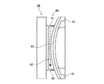
図1は、第1実施形態に係るモータ1Aの縦断面図である。図2は、モータ1Aの内部を、前面側から見た図である。図1および図2に示すように、モータ1Aは、回転部3A、ハウジング21A、バックカバー23A、ブラシカード24A、ブラシ25A、およびコネクタ部材26Aを有する。回転部3Aは、前後に略水平に延びる中心軸9Aを中心として、回転可能に支持される。また、回転部3Aは、コミュテータ33Aを備える。
<1. First Embodiment>
FIG. 1 is a longitudinal sectional view of a
ハウジング21Aは、略カップ状の部材である。ハウジング21Aの内部には、回転部3Aの少なくとも一部分が収容される。バックカバー23Aは、ハウジング21Aの後方側に配置された、略カップ状の部材である。コミュテータ33A、ブラシカード24A、およびブラシ25Aは、ハウジング21Aとバックカバー23Aとで構成される筐体の内部に配置される。ブラシカード24Aは、中心軸9Aに直交する方向に広がっている。また、ブラシ25Aは、ブラシカード24Aの前方側に配置され、コミュテータ33Aに接触する。
The
バックカバー23Aは、第1後壁部231Aと第1周壁部232Aとを有する。第1後壁部231Aは、ブラシカード24Aの後方側において、中心軸9Aに直交する方向に広がっている。第1周壁部232Aは、第1後壁部231Aの外周部から前方へ向けて、略円筒状に延びている。また、第1周壁部232Aは、貫通孔234Aと切り欠き235Aとを有する。図1および図2に示すように、貫通孔234Aは、第1周壁部232Aの下端部付近において、第1周壁部232Aを上下に貫通している。また、図2に示すように、切り欠き235Aは、貫通孔234Aより上側に配置されている。
The
コネクタ部材26Aは、ブラシカード24Aの径方向外側において、バックカバー23Aに固定されている。コネクタ部材26Aは、切り欠き235Aに嵌っている。また、コネクタ部材26Aは、リード線を通す連通孔261Aを有する。
The
図2に示すように、コネクタ部材26Aは、流路溝60Aを有する。流路溝60Aは、コネクタ部材26Aの外表面において、周方向および軸方向に延びている。また、バックカバー23Aの内表面には、流路面70Aが含まれている。流路面70Aは、流路溝60Aの下側において流路溝60Aと対向する部位から貫通孔234Aまで、連続する。
As shown in FIG. 2, the
コネクタ部材26Aに付着した液滴は、図2中の破線矢印90Aのように、流路溝60Aおよび流路面70Aを伝って、貫通孔234Aからバックカバー23Aの外部へ排出される。したがって、Oリングやガスケットを必須構成とすることなく、ブラシ25Aに対する液滴の付着を抑制できる。
The droplets adhering to the
<2.第2実施形態>
<2−1.モータの全体構成>
続いて、本発明の第2実施形態について説明する。図3は、第2実施形態に係るモータ1の縦断面図である。本実施形態のモータは、例えば、自動車に搭載され、エンジン冷却用ファンの駆動源として、使用される。図3に示すように、モータ1は、静止部2と回転部3とを有する。静止部2は、駆動対象となる装置の枠体に固定される。回転部3は、静止部2に対して、回転可能に支持される。
<2. Second Embodiment>
<2-1. Overall configuration of motor>
Subsequently, a second embodiment of the present invention will be described. FIG. 3 is a longitudinal sectional view of the
本実施形態の静止部2は、ハウジング21、複数のマグネット22、バックカバー23、ブラシカード24、複数のブラシ25、コネクタ部材26、前軸受部27、および後軸受部28を有する。図4は、バックカバー23、ブラシカード24、およびコネクタ部材26を、前面側から見た図である。以下の説明では、図3とともに図4も適宜に参照する。
The stationary portion 2 of the present embodiment includes a
ハウジング21は、後方側へ向けて開いた略カップ状の部材である。ハウジング21の内部には、回転部3の少なくとも一部分が、収容される。ハウジング21は、例えば、亜鉛めっき鋼板等の金属により形成される。ただし、ハウジング21の材料に、樹脂等の他の材料が使用されていてもよい。
The
図3に示すように、ハウジング21は、前壁部211と前方周壁部212とを有する。前壁部211は、後述するアーマチュア32の前方において、中心軸9に直交する方向に、略円板状に広がっている。前壁部211の中央には、前軸受部27を保持する前軸受保持部213が、設けられている。前方周壁部212は、前壁部211の外周部から後方側へ向けて、略円筒状に延びている。
As shown in FIG. 3, the
複数のマグネット22は、前方周壁部212の内周面に、固定されている。複数のマグネット22の径方向内側の面は、後述するアーマチュア32と径方向に対向する磁極面となっている。複数のマグネット22は、N極の磁極面とS極の磁極面とが交互に並ぶように、周方向に略等間隔に配列されている。なお、複数のマグネット22に代えて、N極とS極とが周方向に交互に着磁された1つの円環状のマグネットが、使用されていてもよい。
The plurality of
バックカバー23は、前方側へ向けて開いた略カップ状の部材である。バックカバー23は、ハウジング21の後方側に配置されている。バックカバー23は、例えば、亜鉛めっき鋼板等の金属により形成される。ただし、バックカバー23の材料に、樹脂等の他の材料が使用されていてもよい。複数のマグネット22、ブラシカード24、複数のブラシ25、後述するアーマチュア32、および後述するコミュテータ33は、ハウジング21とバックカバー23とで構成される筐体の内部に、収容されている。
The
図3および図4に示すように、バックカバー23は、第1後壁部231と第1周壁部232とを有する。第1後壁部231は、ブラシカード24の後方側において、中心軸9に直交する方向に、略円板状に広がっている。第1後壁部231の中央には、後軸受部28を保持する後軸受保持部233が、設けられている。第1周壁部232は、第1後壁部231の外周部から前方側へ向けて、略円筒状に延びている。
As shown in FIGS. 3 and 4, the
第1周壁部232は、貫通孔234と切り欠き235とを有する。図3に示すように、貫通孔234は、第1周壁部232の下端部付近において、第1周壁部232を上下に貫通している。また、図4に示すように、切り欠き235は、貫通孔234より上側において、第1周壁部232を径方向に貫通している。本実施形態では、中心軸9と略同等の高さ位置、すなわち、貫通孔234から中心軸9に対して約90°離れた位置に、切り欠き235が配置されている。
The first
ブラシカード24は、第1後壁部231の前方側、かつ、第1周壁部232の径方向内側に配置されている。ブラシカード24の材料には、例えば、絶縁体である樹脂が使用される。図3および図4に示すように、ブラシカード24は、第2後壁部241と第2周壁部242とを有する。第2後壁部241は、第1後壁部231の前方側において、中心軸9に直交する方向に、略円板状に広がっている。第2後壁部241の中央には、後軸受保持部233または後述するコミュテータ33を配置するための円孔243が、設けられている。第2周壁部242は、第2後壁部241の外周部から前方側へ向けて、略円筒状に延びている。
The
複数のブラシ25は、ブラシカード24に保持されている。各ブラシ25は、後述するコミュテータ33と接触する導体である。図3に示すように、本実施形態では、第2後壁部241の前方側かつ第2周壁部242の径方向内側に、複数のブラシ25が配置されている。これにより、ブラシ25への液滴の付着が、抑制されている。各ブラシ25は、コミュテータ33のセグメント331に接触する接触面251を有する。また、各ブラシ25は、第2周壁部242との間に介在するばね252により、径方向内側へ付勢されている。これにより、接触面251が、セグメント331に押し付けられる。その結果、ブラシ25とセグメント331とが、電気的に導通する。
The plurality of
コネクタ部材26は、ブラシ25と外部電源とを繋ぐリード線を支持する部材である。コネクタ部材26の材料には、例えば、絶縁体である樹脂が使用される。コネクタ部材26は、ブラシカード24の径方向外側に、配置されている。また、コネクタ部材26は、バックカバー23の切り欠き235に嵌った状態で、バックカバー23に固定されている。
The
また、コネクタ部材26は、1つまたは複数の連通孔261を有する。連通孔261は、コネクタ部材26を径方向に貫通している。外部電源から延びるリード線は、コネクタ部材26の連通孔261を通って、ブラシ25に接続される。
The
前軸受部27および後軸受部28は、回転部3側のシャフト31を回転可能に支持する機構である。本実施形態の前軸受部27および後軸受部28には、例えば、球体を介して外輪と内輪とを相対回転させるボールベアリングが、使用される。前軸受部27の外輪は、ハウジング21の前軸受保持部213に、固定される。後軸受部28の外輪は、バックカバー23の後軸受保持部233に、固定される。また、前軸受部27および後軸受部28の各内輪は、シャフト31に固定される。ただし、ボールベアリングに代えて、すべり軸受や流体軸受等の他方式の軸受が、使用されていてもよい。
The
本実施形態の回転部3は、シャフト31、アーマチュア32、およびコミュテータ33を有する。
The
シャフト31は、前後に略水平に延びる中心軸9に沿って、配置されている。シャフト31は、前軸受部27および後軸受部28に支持され、中心軸9を中心として回転する。また、シャフト31は、ハウジング21の前壁部211より前方に突出した頭部311を有する。頭部311には、駆動対象となる部品、例えばインペラが取り付けられる。
The
アーマチュア32は、複数のマグネット22の径方向内側に、配置されている。アーマチュア32は、アーマチュアコア41とコイル42とを有する。アーマチュアコア41は、例えば、積層鋼板により形成される。アーマチュアコア41は、円環状のコアバック411と、コアバック411から径方向外側へ向けて突出した複数のティース412と、を有する。シャフト31は、コアバック411の径方向内側に圧入されている。複数のティース412は、周方向に等間隔に配列されている。コイル42は、ティース412に巻き付けられた導線により構成される。
The
コミュテータ33は、アーマチュア32より後方側において、シャフト31に固定されている。コミュテータ33の外周面には、導電性の複数のセグメント331が、周方向に等間隔に設けられている。また、各セグメント331には、コイル42から引き出された導線が、電気的に接続されている。
The
外部電源から供給される駆動電流は、リード線、ブラシ25、およびセグメント331を介して、コイル42へ流れる。コイル42に駆動電流が供給されると、ティース412に磁束が生じる。そして、ティース412とマグネット22との間の磁気的吸引力または磁気的反発力によって、周方向のトルクが発生する。その結果、静止部2に対して回転部3が、中心軸9を中心として回転する。また、コミュテータ33が回転すると、各ブラシ25の接触面251は、複数のセグメント331に、順次に接触する。これにより、複数のコイル42に順次に駆動電流が供給される。その結果、回転部3が連続的に回転する。
The drive current supplied from the external power source flows to the
<2−2.排液構造について>
続いて、本実施形態に係るモータ1の排液構造について説明する。
<2-2. About drainage structure>
Next, the drainage structure of the
図5は、バックカバー23、ブラシカード24、およびコネクタ部材26の部分縦断面図である。図4および図5に示すように、コネクタ部材26は、一対の凸部51を有する。一対の凸部51は、コネクタ部材26の周方向の両端部から、径方向内側へ向けて突出している。一方、ブラシカード24の第2周壁部242は、一対の凹部52を有する。一対の凸部51は、一対の凹部52に、それぞれ嵌っている。
FIG. 5 is a partial longitudinal sectional view of the
図5のように、本実施形態では、凸部51の周方向の両端面のうちの少なくとも一方と、凸部51の径方向内側の端面とが、凹部52の表面に接触している。すなわち、凸部51と凹部52とが、連続する複数の面において接触している。これにより、コネクタ部材26とブラシカード24との境界部から径方向内側への液滴の浸入が、抑制されている。
As shown in FIG. 5, in the present embodiment, at least one of both end surfaces in the circumferential direction of the
図6は、コネクタ部材26の上面図である。図7は、コネクタ部材26を前面側から見た図である。図8は、コネクタ部材26の下面図である。図6〜図8に示すように、コネクタ部材26の外表面には、流路溝60が設けられている。コネクタ部材26の外表面に水滴等の液滴が付着すると、当該液滴は、重力および表面張力によって、流路溝60内に捕集される。
FIG. 6 is a top view of the
流路溝60は、上軸方向溝61、前周方向溝62、下軸方向溝63、および後周方向溝64を含む。図6および図7に示すように、上軸方向溝61は、コネクタ部材26の上面において、軸方向に延びている。図6〜図8に示すように、前周方向溝62は、コネクタ部材26の前方側の面において、周方向かつ上下方向に延びている。図7および図8に示すように、下軸方向溝63は、コネクタ部材26の下面において、軸方向に延びている。また、図6および図8に示すように後周方向溝64は、コネクタ部材26の後方側の面において、周方向かつ上下方向に延びている。
The
流路溝60に捕集された液滴は、重力により下軸方向溝63側へ流れる。特に、本実施形態では、上軸方向溝61、前周方向溝62、下軸方向溝63、および後周方向溝64が、環状に繋がっている。このため、上軸方向溝61に捕集された液滴は、前周方向溝62および後周方向溝64のどちらに流れたとしても、下軸方向溝63に到達する。これにより、下軸方向溝63へ効率よく液滴が集められる。
The liquid droplets collected in the
また、図5に示すように、本実施形態では、コネクタ部材26の凸部51の基端部511が、ブラシカード24の第2周壁部242の外周面より、径方向外側に位置している。これにより、第2周壁部242と凸部51との境界における液滴の滞留が、抑制されている。第2周壁部242の外周面に付着した液滴は、図5中の破線矢印91のように、凸部51の基端部511に沿って、上軸方向溝61側へ流れる。
Further, as shown in FIG. 5, in the present embodiment, the
また、図6〜図8に示すように、本実施形態のコネクタ部材26は、流路溝60の径方向内側に、内側堤防面65を有する。内側堤防面65は、流路溝60の径方向内側の縁から、径方向内側へ向けて広がっている。また、内側堤防面65は、ハウジング21またはバックカバー23に、接触する。これにより、流路溝60から径方向内側への液滴の浸入が、抑制されている。
As shown in FIGS. 6 to 8, the
また、図5および図6に示すように、本実施形態のコネクタ部材26は、上軸方向溝61の径方向内側に、テーパ面66を有する。テーパ面66は、上軸方向溝61の径方向内側の縁から径方向内側へ向かうにつれて高さが上がるように、傾斜している。このため、上軸方向溝61に捕集された液滴が、仮に上軸方向溝61から溢れたとしても、当該液滴は、テーパ面66により上軸方向溝61に戻される。これにより、径方向内側への液滴の浸入が、より抑制される。
As shown in FIGS. 5 and 6, the
図5に示すように、テーパ面66は、バックカバー23の第1周壁部232より径方向内側に位置している。このため、第2周壁部242の外周面から凸部51の基端部511へ流れる液滴は、図5中の破線矢印91のように、第1周壁部232とテーパ面66との間を通って、上軸方向溝61に捕集される。
As shown in FIG. 5, the tapered
また、図6に示すように、本実施形態の上軸方向溝61は、前方側へ近づくにつれて径方向の幅が拡大する部分を有する。当該部分の流路抵抗は、後方へ近づくほど大きくなる。このため、上軸方向溝61に捕集された液滴は、図6中の破線矢印92のように、前方側へ誘導される。また、上軸方向溝61から前方側へ向かう液滴は、前周方向溝62を通って、下軸方向溝63へ流れる。
Moreover, as shown in FIG. 6, the upper-axis direction groove |
また、図8に示すように、本実施形態のコネクタ部材26は、下軸方向溝63の径方向内側に、誘導溝67を有する。誘導溝67は、下軸方向溝63から径方向内側へ向けて延びている。また、本実施形態の下軸方向溝63は、誘導溝67へ近づくにつれて径方向の幅が拡大する部分を有する。当該部分の流路抵抗は、誘導溝67へ近づくほど小さくなる。このため、下軸方向溝63に捕集された液滴は、図8中の破線矢印93のように、誘導溝67側へ誘導される。
Further, as shown in FIG. 8, the
図9は、バックカバー23を前面側から見た図である。バックカバー23の切り欠き235は、コネクタ部材26の下側に位置する対向面236を有する。対向面236は、コネクタ部材26の誘導溝67と、上下方向に対向する。また、バックカバー23の内表面は、対向面236から貫通孔234まで連続する流路面70を含んでいる。コネクタ部材26の流路溝60に捕集された液滴は、誘導溝67から対向面236へ流れる。そして、当該液滴は、図9中の破線矢印94,95のように、流路面70を伝って貫通孔234へ流れ、バックカバー23の外部へ排出される。
FIG. 9 is a view of the
このように、本実施形態のモータ1では、コネクタ部材26に付着した液滴が、流路溝60および流路面70を伝って、貫通孔234からバックカバー23の外部へ排出される。したがって、Oリングやガスケットを必須構成とすることなく、ブラシ25に対する液滴の付着を抑制できる。その結果、モータ1の部品点数を抑制できるとともに、モータ1の製造コストも抑制できる。
As described above, in the
図10は、ハウジング21、バックカバー23、ブラシカード24、およびコネクタ部材26の部分横断面図である。図10に示すように、本実施形態のコネクタ部材26は、後周方向溝64の径方向内側に、板状突出部262を有する。板状突出部262は、第1後壁部231の前方側の面に沿って、径方向内側へ延びている。板状突出部262の後方側の面は、第1後壁部231の前方側の面に、接触している。また、板状突出部262の径方向内側の端縁部は、ブラシカード24の径方向外側の端縁部より、径方向内側に位置している。
FIG. 10 is a partial cross-sectional view of the
このため、仮に、第1後壁部231と板状突出部262との間から径方向内側へ、液滴が浸入したとしても、当該液滴は、図10中の破線矢印96のように、第1後壁部231の前方側の面に沿って流れる。これにより、ブラシカード24の前方側への液滴の浸入が、抑制される。その結果、ブラシ25への液滴の付着が、より抑制される。
For this reason, even if a droplet enters from the first
図11および図12は、ハウジング21、バックカバー23、およびブラシカード24の部分断面図である。図12は、貫通孔234を含む縦断面を示している。図11は、図12とは異なる周方向位置における断面を示している。図11に示すように、バックカバー23の第1後壁部231は、内側後壁部81、内側周壁部82、および外側後壁部83を有する。内側後壁部81は、ブラシカード24の第2後壁部241から隙間を介して後方側において、中心軸9に直交する方向に広がっている。内側周壁部82は、内側後壁部81の外周部から前方へ向けて、略円筒状に延びている。外側後壁部83は、内側周壁部82の前端部から径方向外側へ向けて広がっている。外側後壁部83の径方向外側の端縁部は、第1周壁部232の後端部と繋がっている。
11 and 12 are partial cross-sectional views of the
また、ブラシカード24は、略円環状の脚部244を有する。脚部244は、第2後壁部241の外周部から、後方側へ向けて延びている。そして、本実施形態では、バックカバー23の外側後壁部83と、ブラシカード24の脚部244とが、略円環状の接触部80において接触している。すなわち、バックカバー23またはブラシカード24が、略円環状の接触部80を有する。接触部80は、第1周壁部232の内周面から、隙間を介して径方向内側に位置する。
The
図9および図11に示すように、バックカバー23の流路面70は、第1流路面71と第2流路面72とを含む。第1流路面71は、接触部80より径方向外側に位置する。また、第1流路面71は、第1周壁部232の内周面および外側後壁部83の前方側の面に、属する。第2流路面72は、接触部80より径方向内側に位置する。第2流路面72は、内側後壁部81の前方側の面および内側周壁部82の内周面に、属する。
As shown in FIGS. 9 and 11, the flow path surface 70 of the
第1周壁部232と接触部80との間に浸入した液滴は、図9および図12の破線矢印94のように、第1流路面71を伝って、貫通孔234へ流れる。また、接触部80より径方向内側へ浸入した液滴は、図9および図12の破線矢印95のように、第2流路面72を伝って、貫通孔234へ流れる。このように、本実施形態のモータ1は、バックカバー23の内部に浸入した液滴を、2つの経路で排出できる。すなわち、接触部80の径方向外側および径方向内側のいずれに存在する液滴も、貫通孔234からバックカバー23の外部へ排出できる。したがって、バックカバー23の内部から、液滴を効率よく排出できる。その結果、ブラシ25に対する液滴の付着を抑制できる。
The droplet that has entered between the first
なお、図9に示すように、内側周壁部82および外側後壁部83は、貫通孔234と径方向に重なる位置には、設けられていない。このため、図12に示すように、接触部80は、貫通孔234と径方向に重なる位置において、途切れている。したがって、第2流路面72を伝う液滴を、接触部80の途切れた部分を通って、貫通孔234へ流すことができる。特に、本実施形態では、図9のように、内側後壁部81の前方側の面が、段差のない平坦面となっている。このため、第2流路面72において、液滴を、より効率よく貫通孔234へ流すことができる。
As shown in FIG. 9, the inner
貫通孔234から排出される液滴は、コネクタ部材26の流路溝60を通ってバックカバー23内へ誘導された液滴だけではない。例えば、ハウジング21に設けられた貫通孔から浸入した液滴や、ハウジング21とバックカバー23との境界部から浸入した液滴も、第1流路面71および第2流路面72を伝って、貫通孔234からバックカバー23の外部へ排出される。
The liquid droplets discharged from the through
また、図11に示すように、本実施形態では、バックカバー23の第1周壁部232の内周面と、ブラシカード24の第2周壁部242の外周面とが、径方向に隙間を介して対向する。これにより、第1流路面71からブラシ25側への液滴の移動が、より抑制される。
Further, as shown in FIG. 11, in the present embodiment, the inner peripheral surface of the first
また、図11に示すように、本実施形態では、バックカバー23の第1後壁部231の前方側の面と、ブラシカード24の第2後壁部241の後方側の面とが、軸方向に隙間を介して対向する。これにより、第2流路面72からブラシ25側への液滴の移動が、より抑制される。この軸方向の隙間は、本実施形態では、バックカバー23の外側後壁部83と、ブラシカード24の脚部244とを接触させることにより、実現されている。ただし、外側後壁部83および脚部244の一方が、省略されていてもよい。
In addition, as shown in FIG. 11, in the present embodiment, the front side surface of the first
また、本実施形態のモータ1は、駆動時に、ハウジング21およびバックカバー23の内部に、冷却用の空気を取り込む。具体的には、図12中の破線矢印97のように、貫通孔234からバックカバー23の内部へ、気体が流入する。この気流は、回転部3の回転により生じる。当該気体により、ブラシ25やコイル42が冷却される。
Further, the
ただし、本実施形態では、ブラシカード24の第2周壁部242の前端部が、貫通孔234より前方に位置する。したがって、矢印97の気体が、第2周壁部242の径方向内側へ直接的に吹き込むことが、抑制される。したがって、矢印97の気体に液滴が混在していたとしても、当該液滴の第2周壁部242より径方向内側への浸入が、抑制される。
However, in the present embodiment, the front end portion of the second
また、図12に示すように、本実施形態のブラシカード24は、オーバーハング部245を有する。オーバーハング部245は、第2周壁部242の外周面から、径方向外側へ向けて突出している。また、オーバーハング部245は、貫通孔234の後端部より、前方側に位置している。これにより、矢印97の気体の前方側への回り込みが、より抑制される。特に、本実施形態では、オーバーハング部245の径方向外側の面が、径方向外側へ向かうにつれて前方へ変位する傾斜面246となっている。また、オーバーハング部245の前方側の面は、ハウジング21の後端部と接触している。これにより、気体の前方側への回り込みが、さらに抑制されている。
Also, as shown in FIG. 12, the
<3.変形例>
以上、本発明の例示的な実施形態について説明したが、本発明は上記の実施形態に限定されるものではない。
<3. Modification>
As mentioned above, although exemplary embodiment of this invention was described, this invention is not limited to said embodiment.
図13は、一変形例に係るハウジング21B、バックカバー23B、およびブラシカード24Bの部分縦断面図である。図13の例では、オーバーハング部245Bと、第1周壁部232Bの内周面または前方周壁部212Bの内周面との間に、径方向の隙間が介在する。このようにすれば、ハウジング21Bの内部に浸入した液滴を、図13中の破線矢印98のように、前方周壁部212Bの内周面および第1周壁部232Bの内周面を伝って、貫通孔234からバックカバー23Bの外部へ排出させることができる。
FIG. 13 is a partial vertical cross-sectional view of the
特に、図13の例では、オーバーハング部245Bの前方側の面が、径方向外側へ向かうにつれて後方側へ変位する傾斜面246Bとなっている。このため、オーバーハング部245Bの径方向外側において、液滴を貫通孔234B側へより効率よく誘導できる。
In particular, in the example of FIG. 13, the front side surface of the
図14は、他の変形例に係るハウジング21C、バックカバー23C、およびブラシカード24Cの部分縦断面図である。図14の例では、バックカバー23Cとブラシカード24Cとの接触部80Cが、貫通孔234Cと径方向に重なる位置において、途切れていない。すなわち、貫通孔234Cと径方向に重なる位置においても、バックカバー23Cの第1後壁部231Cと、ブラシカード24Cの脚部244Cとが、接触している。
FIG. 14 is a partial longitudinal sectional view of a
ただし、図14の例では、貫通孔234Cと径方向に重なる位置において、ブラシカード24Cの脚部244Cが、接触部80Cより径方向内側から径方向外側へ貫通する流路孔247Cを有している。このため、第2流路面72Cを伝う液滴を、流路孔247Cを通って、貫通孔234側へ流すことができる。なお、脚部244Cに、流路孔247Cに代えて切り欠きが設けられていてもよい。
However, in the example of FIG. 14, the
本発明のモータは、車載用のファンを回転させるためのモータであってもよく、他の用途に使用されるモータであってもよい。例えば、本発明のモータは、自動車のパワーステアリングの駆動源として、使用されるものであってもよい。また、本発明のモータは、家電製品、OA機器、医療機器等に搭載され、各種の駆動力を発生させるものであってもよい。 The motor of the present invention may be a motor for rotating a vehicle-mounted fan, or may be a motor used for other applications. For example, the motor of the present invention may be used as a drive source for power steering of an automobile. The motor of the present invention may be mounted on home appliances, OA equipment, medical equipment, etc., and generate various driving forces.
ただし、本発明は、液滴が掛かりやすい環境で使用されるモータに、特に有用である。したがって、本発明は、自動車等の輸送機器に搭載されるモータや、屋外に設置されるサーバ、ルータ、通信基地、スイッチ装置等を冷却するためのファンモータに、特に有用である。 However, the present invention is particularly useful for a motor that is used in an environment in which droplets are easily applied. Therefore, the present invention is particularly useful for a motor mounted on a transportation device such as an automobile and a fan motor for cooling a server, a router, a communication base, a switch device and the like installed outdoors.
バックカバーに設けられる貫通孔の数は、上記の実施形態のように1つであってもよく、2つ以上であってもよい。また、コネクタ部材の位置は、必ずしも、貫通孔から中心軸9に対して約90°離れた位置でなくてもよい。また、各部材の細部の形状については、本願の各図面に示した形状と相違していてもよい。また、本願の排液構造と、Oリングやガスケット等のシール部材とが、併用されていてもよい。
The number of through holes provided in the back cover may be one as in the above embodiment, or may be two or more. Further, the position of the connector member does not necessarily have to be a position that is about 90 ° away from the through hole with respect to the
また、上記の実施形態や変形例に登場した各要素を、矛盾が生じない範囲で、適宜に組み合わせてもよい。 Moreover, you may combine suitably each element which appeared in said embodiment and modification in the range which does not produce inconsistency.
本発明は、モータに利用できる。 The present invention can be used for a motor.
1,1A モータ
2 静止部
3,3A 回転部
9,9A 中心軸
21,21A,21B,21C ハウジング
22 マグネット
23,23A,23B,23C バックカバー
24,24A,24B,24C ブラシカード
25,25A ブラシ
26,26A コネクタ部材
27 前軸受部
28 後軸受部
31 シャフト
32 アーマチュア
33,33A コミュテータ
41 アーマチュアコア
42 コイル
51 凸部
52 凹部
60,60A 流路溝
61 上軸方向溝
62 前周方向溝
63 下軸方向溝
64 後周方向溝
65 内側堤防面
66 テーパ面
67 誘導溝
70,70A 流路面
71 第1流路面
72,72C 第2流路面
80,80C 接触部
81 内側後壁部
82 内側周壁部
83 外側後壁部
211 前壁部
212,212B 前方周壁部
231,231A,231C 第1後壁部
232,232A,232B 第1周壁部
234,234A,234B,234C 貫通孔
235,235A 切り欠き
241 第2後壁部
242 第2周壁部
244,244C 脚部
245,245B オーバーハング部
246,246B 傾斜面
247C 流路孔
261 連通孔
262 板状突出部
1, 1A motor 2
Claims (13)
前記回転部の少なくとも一部分を収容する略カップ状のハウジングと、
前記ハウジングの後方側に配置され、前記ハウジングとともに筐体を構成する略カップ状のバックカバーと、
前記筐体の内部に配置され、前記中心軸に直交する方向に広がるブラシカードと、
前記ブラシカードの前方側に配置され、前記コミュテータに接触するブラシと、
前記ブラシカードの径方向外側において、前記バックカバーに固定されたコネクタ部材と、
を有し、
前記バックカバーは、
前記ブラシカードの後方側において、前記中心軸に直交する方向に広がる第1後壁部と、
前記第1後壁部の外周部から前方へ向けて延びる略円筒状の第1周壁部と、
を有し、
前記第1周壁部は、
前記第1周壁部の下端部付近において、前記第1周壁部を上下に貫通する貫通孔と、
前記貫通孔より上側に配置された切り欠きと、
を有し、
前記コネクタ部材は、前記切り欠きに嵌るとともに、リード線を通す連通孔を有し、
前記コネクタ部材の外表面に、周方向および軸方向に延びる流路溝が設けられ、
前記バックカバーの内表面が、前記流路溝の下側において流路溝と対向する部位から前記貫通孔まで連続する流路面を含んでいるモータ。 A rotating part that is supported rotatably about a central axis extending substantially horizontally in the front-rear direction and that includes a commutator;
A generally cup-shaped housing that houses at least a portion of the rotating portion;
A substantially cup-shaped back cover disposed on the rear side of the housing and constituting a housing together with the housing;
A brush card that is arranged inside the housing and spreads in a direction perpendicular to the central axis;
A brush disposed on the front side of the brush card and in contact with the commutator;
On the radially outer side of the brush card, a connector member fixed to the back cover,
Have
The back cover is
On the rear side of the brush card, a first rear wall portion extending in a direction perpendicular to the central axis,
A substantially cylindrical first peripheral wall portion extending forward from the outer peripheral portion of the first rear wall portion;
Have
The first peripheral wall portion is
In the vicinity of the lower end portion of the first peripheral wall portion, a through-hole penetrating the first peripheral wall portion up and down,
A notch disposed above the through hole;
Have
The connector member fits into the notch and has a communication hole through which a lead wire passes.
On the outer surface of the connector member, a channel groove extending in the circumferential direction and the axial direction is provided,
A motor in which an inner surface of the back cover includes a flow path surface continuous from a portion facing the flow path groove on the lower side of the flow path groove to the through hole.
前記流路溝は、前記コネクタ部材の上面において軸方向に延びる上軸方向溝を含み、
前記コネクタ部材は、前記上軸方向溝の径方向内側の縁から径方向内側へ向かうにつれて高さが上がるように傾斜したテーパ面を有するモータ。 The motor according to claim 1,
The flow path groove includes an upper axial groove extending in the axial direction on the upper surface of the connector member,
The connector member is a motor having a tapered surface inclined such that the height increases from the radially inner edge of the upper axial groove toward the radially inner side.
前記上軸方向溝の径方向の幅が、前方側へ近づくにつれて拡大しているモータ。 The motor according to claim 2,
A motor in which a radial width of the upper axial groove increases as it approaches the front side.
前記流路溝は、
前記コネクタ部材の下面において軸方向に延びる下軸方向溝と、
前記下軸方向溝から径方向内側へ向けて延びる誘導溝と、
を含み、
前記誘導溝と前記流路面とが、上下方向に対向しているモータ。 In the motor according to any one of claims 1 to 3,
The channel groove is
A lower axial groove extending in the axial direction on the lower surface of the connector member;
A guide groove extending radially inward from the lower axial groove;
Including
A motor in which the guide groove and the flow path face each other in the vertical direction.
前記下軸方向溝の径方向の幅が、前記誘導溝へ近づくにつれて拡大しているモータ。 The motor according to claim 4,
A motor in which a width in a radial direction of the lower axial direction groove is increased as it approaches the guide groove.
前記流路溝が、前記コネクタ部材の外表面において、環状に繋がっているモータ。 In the motor according to any one of claims 1 to 5,
The motor in which the flow channel is connected in an annular shape on the outer surface of the connector member.
前記コネクタ部材は、前記流路溝の径方向内側の縁から径方向内側へ向けて広がる内側堤防面を有し、
前記内側堤防面と、前記ハウジングまたは前記バックカバーとが、接触しているモータ。 In the motor according to any one of claims 1 to 6,
The connector member has an inner bank surface that extends radially inward from the radially inner edge of the flow channel groove,
A motor in which the inner bank surface is in contact with the housing or the back cover.
前記コネクタ部材は、前記第1後壁部の前方側の面に沿って径方向内側へ延びる板状突出部を有し、
前記板状突出部の径方向内側の端縁部は、前記ブラシカードの径方向外側の端縁部より、径方向内側に位置しているモータ。 The motor according to any one of claims 1 to 7,
The connector member has a plate-like protrusion that extends radially inward along the front side surface of the first rear wall,
The edge part inside the radial direction of the said plate-shaped protrusion part is a motor located in the radial direction inner side from the edge part outside the radial direction of the said brush card | curd.
前記第1周壁部の内周面と、前記ブラシカードとが、径方向に隙間を介して対向し、
前記流路面は、前記第1周壁部の内周面を含むモータ。 In the motor according to any one of claims 1 to 8,
The inner peripheral surface of the first peripheral wall portion and the brush card face each other through a gap in the radial direction,
The flow path surface is a motor including an inner peripheral surface of the first peripheral wall portion.
前記第1後壁部の前方側の面と、前記ブラシカードとが、軸方向に隙間を介して対向し、
前記流路面は、前記第1後壁部の前方側の面を含むモータ。 In the motor according to any one of claims 1 to 9,
The surface on the front side of the first rear wall portion and the brush card face each other via a gap in the axial direction,
The said flow path surface is a motor containing the surface of the front side of a said 1st rear wall part.
前記ブラシカードは、
前記第1後壁部の前方側に配置された第2後壁部と、
前記第2後壁部の外周部から前方へ向けて延びる略円筒状の第2周壁部と、
を有し、
前記ブラシが、前記第2後壁部の前方側かつ前記第2周壁部の径方向内側に配置されているモータ。 In the motor according to any one of claims 1 to 10,
The brush card is
A second rear wall disposed on the front side of the first rear wall;
A substantially cylindrical second peripheral wall portion extending forward from the outer peripheral portion of the second rear wall portion;
Have
The motor in which the brush is disposed on the front side of the second rear wall and on the radially inner side of the second peripheral wall.
前記コネクタ部材は、周方向の両端部から径方向内側へ向けて突出する一対の凸部を有し、
前記第2周壁部は、前記一対の凸部が嵌る一対の凹部を有し、
前記凸部の表面と、前記凹部の表面とが、接触しているモータ。 The motor according to claim 11, wherein
The connector member has a pair of protrusions protruding radially inward from both ends in the circumferential direction,
The second peripheral wall portion has a pair of concave portions into which the pair of convex portions are fitted,
The motor which the surface of the said convex part and the surface of the said recessed part are contacting.
前記凸部の基端部は、前記第2周壁部の外周面より径方向外側に位置しているモータ。 The motor according to claim 12, wherein
A motor in which a base end portion of the convex portion is located radially outward from an outer peripheral surface of the second peripheral wall portion.
Priority Applications (6)
| Application Number | Priority Date | Filing Date | Title |
|---|---|---|---|
| JP2012116843A JP5843162B2 (en) | 2012-05-22 | 2012-05-22 | motor |
| DE201311002631 DE112013002631T5 (en) | 2012-05-22 | 2013-05-17 | ENGINE |
| PCT/JP2013/003159 WO2013175749A1 (en) | 2012-05-22 | 2013-05-17 | Motor |
| CN201380026881.8A CN104508950B (en) | 2012-05-22 | 2013-05-17 | Motor |
| IN2319MUN2014 IN2014MN02319A (en) | 2012-05-22 | 2013-05-17 | |
| US14/399,264 US9960652B2 (en) | 2012-05-22 | 2013-05-17 | Motor |
Applications Claiming Priority (1)
| Application Number | Priority Date | Filing Date | Title |
|---|---|---|---|
| JP2012116843A JP5843162B2 (en) | 2012-05-22 | 2012-05-22 | motor |
Publications (2)
| Publication Number | Publication Date |
|---|---|
| JP2013243891A JP2013243891A (en) | 2013-12-05 |
| JP5843162B2 true JP5843162B2 (en) | 2016-01-13 |
Family
ID=49623459
Family Applications (1)
| Application Number | Title | Priority Date | Filing Date |
|---|---|---|---|
| JP2012116843A Expired - Fee Related JP5843162B2 (en) | 2012-05-22 | 2012-05-22 | motor |
Country Status (6)
| Country | Link |
|---|---|
| US (1) | US9960652B2 (en) |
| JP (1) | JP5843162B2 (en) |
| CN (1) | CN104508950B (en) |
| DE (1) | DE112013002631T5 (en) |
| IN (1) | IN2014MN02319A (en) |
| WO (1) | WO2013175749A1 (en) |
Families Citing this family (7)
| Publication number | Priority date | Publication date | Assignee | Title |
|---|---|---|---|---|
| FR3019404B1 (en) * | 2014-03-31 | 2017-11-03 | Valeo Equip Electr Moteur | PLATINUM BRUSH HOLDER BRACKET FOR ELECTRIC MOTOR AND CORRESPONDING BRUSH HOLDER |
| JP6528501B2 (en) * | 2015-03-26 | 2019-06-12 | 日本電産株式会社 | Motor and fan |
| CN111066229A (en) * | 2017-09-29 | 2020-04-24 | 日本电产株式会社 | Motor with a stator having a stator core |
| US10641286B2 (en) * | 2017-11-07 | 2020-05-05 | Air Cool Industrial Co., Ltd. | Waterproof structure of wall-mounted fan housing |
| FR3081632B1 (en) * | 2018-05-28 | 2020-05-08 | Valeo Equipements Electriques Moteur | SEALED VEHICLE MOTOR STARTER WITH ANGULARLY WEDNED BRUSH WASHER |
| CN111384810B (en) * | 2018-12-28 | 2022-11-11 | 日本电产(大连)有限公司 | Brush motor and electrical equipment |
| EP3836364B1 (en) * | 2019-03-28 | 2024-08-14 | Aisin Corporation | Rotary electric machine |
Family Cites Families (23)
| Publication number | Priority date | Publication date | Assignee | Title |
|---|---|---|---|---|
| JPS63127258U (en) | 1987-02-13 | 1988-08-19 | ||
| JPH0275958U (en) * | 1988-11-26 | 1990-06-11 | ||
| DE3840273A1 (en) * | 1988-11-30 | 1990-05-31 | Vdo Schindling | Bearing plate for the drive motor of a conveyor pump |
| JPH02211379A (en) * | 1989-02-10 | 1990-08-22 | Mitsubishi Electric Corp | Drain device for starting electric motor |
| JPH0723961U (en) * | 1993-10-01 | 1995-05-02 | 国産電機株式会社 | DC motor |
| JP3051656B2 (en) | 1995-06-13 | 2000-06-12 | アスモ株式会社 | Automotive motor cooling structure |
| JPH09261906A (en) | 1996-03-21 | 1997-10-03 | Asmo Co Ltd | Waterproofing structure for motor |
| JPH10252622A (en) * | 1997-01-09 | 1998-09-22 | Denso Corp | Starter |
| JP3134244B2 (en) * | 1997-12-01 | 2001-02-13 | ジェコー株式会社 | Motor waterproof structure |
| US6448676B1 (en) * | 1999-05-18 | 2002-09-10 | Siemens Automotive Inc. | Pulse width modulated engine cooling fan motor with integrated MOSFET |
| JP4372970B2 (en) * | 2000-05-31 | 2009-11-25 | アスモ株式会社 | motor |
| JP4593832B2 (en) | 2001-06-25 | 2010-12-08 | アスモ株式会社 | Motor waterproof structure |
| JP4013254B2 (en) * | 2003-06-11 | 2007-11-28 | 株式会社デンソー | Fuel pump |
| FR2856852B1 (en) | 2003-06-27 | 2006-09-29 | Asmo Co Ltd | AIR CONDITIONER ENGINE ASSEMBLY FOR VEHICLES |
| JP3971349B2 (en) * | 2003-06-27 | 2007-09-05 | アスモ株式会社 | Waterproof structure for motors for vehicle air conditioning |
| JP4473644B2 (en) | 2004-05-20 | 2010-06-02 | 矢崎総業株式会社 | Motor waterproof structure |
| JP4337669B2 (en) * | 2004-07-13 | 2009-09-30 | 株式会社デンソー | Electric blower fan device for vehicles |
| JP2006174589A (en) * | 2004-12-15 | 2006-06-29 | Denso Corp | Rotary electric machine |
| JP4897442B2 (en) | 2006-11-22 | 2012-03-14 | 株式会社ティラド | Fan motor drain structure |
| US7741743B2 (en) * | 2007-10-30 | 2010-06-22 | Showa Corporation | Feeder line drawing structure of motor for ship propeller |
| CN201690289U (en) * | 2010-05-11 | 2010-12-29 | 许晓华 | Structure used for connecting carbon brush mounting plate with end cover |
| JP5652128B2 (en) * | 2010-10-29 | 2015-01-14 | 株式会社デンソー | Drainage structure of rotating electric machine |
| CN202014151U (en) * | 2011-03-21 | 2011-10-19 | 杜权辉 | Split-type carbon brush sleeve positioning structure for DC motor |
-
2012
- 2012-05-22 JP JP2012116843A patent/JP5843162B2/en not_active Expired - Fee Related
-
2013
- 2013-05-17 IN IN2319MUN2014 patent/IN2014MN02319A/en unknown
- 2013-05-17 US US14/399,264 patent/US9960652B2/en active Active
- 2013-05-17 WO PCT/JP2013/003159 patent/WO2013175749A1/en active Application Filing
- 2013-05-17 CN CN201380026881.8A patent/CN104508950B/en not_active Expired - Fee Related
- 2013-05-17 DE DE201311002631 patent/DE112013002631T5/en not_active Withdrawn
Also Published As
| Publication number | Publication date |
|---|---|
| WO2013175749A1 (en) | 2013-11-28 |
| JP2013243891A (en) | 2013-12-05 |
| US9960652B2 (en) | 2018-05-01 |
| IN2014MN02319A (en) | 2015-08-07 |
| CN104508950B (en) | 2017-05-17 |
| CN104508950A (en) | 2015-04-08 |
| DE112013002631T5 (en) | 2015-05-07 |
| US20150084460A1 (en) | 2015-03-26 |
Similar Documents
| Publication | Publication Date | Title |
|---|---|---|
| JP5843162B2 (en) | motor | |
| JP5843163B2 (en) | motor | |
| US8922083B2 (en) | Rotor | |
| JP4483948B2 (en) | Rotating electric machine | |
| US9653960B2 (en) | Motor and blower | |
| JP5888490B2 (en) | motor | |
| JP2020099197A (en) | motor | |
| JP5858220B2 (en) | motor | |
| JP2017221021A (en) | Stator unit, motor and blower | |
| JP2014204608A (en) | Rotary electric machine | |
| JP2014064433A (en) | Rotor shaft of rotary electric machine | |
| JP5745347B2 (en) | Rotor and motor | |
| JP5924352B2 (en) | Rotating electric machine | |
| JP2018068067A (en) | Rotary electric machine | |
| JP2019161832A (en) | Motor and fan motor | |
| JP2019030154A (en) | Stator and motor | |
| JP2016049005A (en) | Motor | |
| EP3364527A1 (en) | Electric motor and blower | |
| JP2000032689A (en) | Stator of electric motor and its manufacturing method therefor | |
| JP2013005531A (en) | Outer rotor type rotary electric machine | |
| CN111066229A (en) | Motor with a stator having a stator core | |
| US10069372B2 (en) | Motor | |
| JPWO2019123962A1 (en) | Rotor and motor | |
| WO2023190172A1 (en) | Rotor, rotary electric machine, and drive device | |
| JP7275430B2 (en) | motor |
Legal Events
| Date | Code | Title | Description |
|---|---|---|---|
| A621 | Written request for application examination |
Free format text: JAPANESE INTERMEDIATE CODE: A621 Effective date: 20150316 |
|
| TRDD | Decision of grant or rejection written | ||
| A01 | Written decision to grant a patent or to grant a registration (utility model) |
Free format text: JAPANESE INTERMEDIATE CODE: A01 Effective date: 20151023 |
|
| A61 | First payment of annual fees (during grant procedure) |
Free format text: JAPANESE INTERMEDIATE CODE: A61 Effective date: 20151105 |
|
| R151 | Written notification of patent or utility model registration |
Ref document number: 5843162 Country of ref document: JP Free format text: JAPANESE INTERMEDIATE CODE: R151 |
|
| R250 | Receipt of annual fees |
Free format text: JAPANESE INTERMEDIATE CODE: R250 |
|
| R250 | Receipt of annual fees |
Free format text: JAPANESE INTERMEDIATE CODE: R250 |
|
| R250 | Receipt of annual fees |
Free format text: JAPANESE INTERMEDIATE CODE: R250 |
|
| R250 | Receipt of annual fees |
Free format text: JAPANESE INTERMEDIATE CODE: R250 |
|
| LAPS | Cancellation because of no payment of annual fees |