JP5842111B2 - Antenna switching reception system - Google Patents
Antenna switching reception system Download PDFInfo
- Publication number
- JP5842111B2 JP5842111B2 JP2010153421A JP2010153421A JP5842111B2 JP 5842111 B2 JP5842111 B2 JP 5842111B2 JP 2010153421 A JP2010153421 A JP 2010153421A JP 2010153421 A JP2010153421 A JP 2010153421A JP 5842111 B2 JP5842111 B2 JP 5842111B2
- Authority
- JP
- Japan
- Prior art keywords
- signal
- antenna
- antenna switching
- received
- reception system
- Prior art date
- Legal status (The legal status is an assumption and is not a legal conclusion. Google has not performed a legal analysis and makes no representation as to the accuracy of the status listed.)
- Active
Links
Images


Description
本発明は、無線通信システムにおいてアンテナを切り替えて受信するアンテナ切り替え受信システムに関する。 The present invention relates to an antenna switching reception system for switching and receiving antennas in a wireless communication system.
無線通信システムにおいて、マルチパスフェージングによるレベル劣化が課題のひとつとして挙げられる。受信アンテナが受信する信号は、送信アンテナから直接受信アンテナに入力される信号だけではなく、複数の異なる経路を経て入力される信号も存在する。そのため、各々異なる遅延時間を持った信号(マルチパス)も受信アンテナに入力されてしまうため、受信アンテナ端で信号同士が重なり合い、打ち消し合うなどして受信レベルが劣化してしまう。これがマルチパスフェージングによるレベル劣化と称される現象である。 In wireless communication systems, level degradation due to multipath fading is one of the problems. Signals received by the receiving antenna include not only signals directly input from the transmitting antenna to the receiving antenna but also signals input through a plurality of different paths. For this reason, signals (multipaths) having different delay times are also input to the receiving antenna, so that the reception level deteriorates by overlapping and canceling signals at the receiving antenna end. This is a phenomenon called level degradation due to multipath fading.
このマルチパスフェージングによるレベル劣化の影響を回避するための代表的な方策として、OFDMなどのマルチキャリア伝送技術がある。これは伝送する情報を複数のキャリア(サブキャリア)に分けて広い周波数帯域で伝送するため、マルチパスフェージングによるレベル劣化の影響を低減できるという技術である。しかしながら、OFDM伝送ではフーリエ逆変換及びフーリエ変換により周波数軸と時間軸を変換して処理する複雑な構成が必要となり回路規模が増大してしまうため、低コスト化を図るのが困難であるという欠点があった。 As a representative measure for avoiding the influence of level deterioration due to multipath fading, there is a multicarrier transmission technique such as OFDM. This is a technology that can reduce the influence of level degradation due to multipath fading because information to be transmitted is divided into a plurality of carriers (subcarriers) and transmitted in a wide frequency band. However, in OFDM transmission, it is difficult to reduce the cost because it requires a complicated configuration for processing by transforming the frequency axis and time axis by inverse Fourier transform and Fourier transform, which increases the circuit scale. was there.
また、複数のアンテナを切り替える「切り替えダイバーシチ」、「選択ダイバーシチ」や各アンテナでの受信信号を合成する「合成ダイバーシチ」による対策がある。これらはマルチパスフェージングによる影響は受信器の場所や電波の偏波面などによって異なることを利用した方策である。「選択ダイバーシチ」は、複数のアンテナでの受信レベルを監視しておき、最適なアンテナで信号を受信する技術であるが、アンテナの個数分の受信器が必要となるため回路規模が大きくなるという欠点があった。また、「合成ダイバーシチ」は複数のアンテナで受信した信号の位相を揃えて合成する技術であるが、こちらもアンテナの個数分の受信器及び各信号の位相を合わせる移相器が必要となるため回路規模が大きくなるという欠点があった。 Further, there are measures by “switching diversity”, “selective diversity” for switching a plurality of antennas, and “combining diversity” for combining received signals at each antenna. These measures are based on the fact that the effects of multipath fading differ depending on the location of the receiver and the plane of polarization of the radio wave. “Selective diversity” is a technology that monitors reception levels at multiple antennas and receives signals with optimal antennas, but requires as many receivers as the number of antennas, which increases the circuit scale. There were drawbacks. “Combining diversity” is a technology that combines the phases of signals received by multiple antennas, but this also requires as many receivers as the number of antennas and a phase shifter that matches the phases of each signal. There was a drawback that the circuit scale was increased.
「切り替えダイバーシチ」は一方のアンテナでマルチパスフェージングの影響がある場合は、もう一方のアンテナに切り替えることによりマルチパスフェージングの影響を低減するという技術である(例えば、特許文献1参照)。近年、携帯用無線機器の普及により、アンテナ切り替え部も小型化や低コスト化が要求されており、1つの受信機で構成できるため、開発が容易で回路規模が小さく低コスト化が図れる「切り替えダイバーシチ」が様々な無線器に搭載されている。 “Switching diversity” is a technique for reducing the influence of multipath fading by switching to the other antenna when there is an influence of multipath fading on one antenna (see, for example, Patent Document 1). In recent years, with the widespread use of portable wireless devices, the antenna switching unit is also required to be downsized and reduced in cost, and can be configured with a single receiver, so that it is easy to develop and the circuit scale is small and the cost can be reduced. Diversity "is installed in various radio devices.
しかしながら、「切り替えダイバーシチ」においては、切り替え先のアンテナでの受信レベルはアンテナを切り替えるまで分からない。そのため、もし切り替え先のアンテナでの受信レベルがさらに低かった場合には、より劣悪な条件で信号を受信しなければならないという欠点がある。 However, in “switching diversity”, the reception level at the switching destination antenna is not known until the antenna is switched. For this reason, if the reception level at the antenna to be switched to is lower, there is a disadvantage that the signal must be received under worse conditions.
さらに無線LANでは、複数のフレーム(ペイロード信号の一塊)を受信し、エラーが複数のフレームに亘って検出された際にアンテナを切り替えるシステム、つまりエラーが発生した後のアンテナ切り替えを基本としている。発生したエラーに対しては再度同じフレームを送信器に送ってもらうことにより対応している(再送機能)。しかしながら、マルチパスフェージングにより通信環境が劣悪な状況では再送回数が増え、音声や映像など高速で次々に新しいペイロード信号を受信する必要がある機器には不向きとなる。 Further, the wireless LAN is based on a system that receives a plurality of frames (a lump of payload signals) and switches antennas when an error is detected over a plurality of frames, that is, antenna switching after an error occurs. The generated error is dealt with by sending the same frame again to the transmitter (retransmission function). However, when the communication environment is poor due to multipath fading, the number of retransmissions increases, making it unsuitable for devices that need to receive new payload signals one after another at high speed, such as voice and video.
本発明は、簡素な構成で、マルチパスが多い環境下においても正確に受信レベルの高いアンテナを選択することにより、マルチパスフェージングによるレベル変動の影響を低減できるアンテナ切り替え受信システムを提供することを目的とする。 The present invention provides an antenna switching reception system that can reduce the influence of level fluctuations due to multipath fading by accurately selecting an antenna having a high reception level even in an environment with many multipaths with a simple configuration. Objective.
上記目的を達成するために本発明のアンテナ切り替え受信システムは、複数のアンテナを切り替えて無線信号を受信するアンテナ切り替え受信システムにおいて、
送信システムからは、プリアンブル信号と、少なくとも1つのテスト信号とペイロード信号がこの順番で送信され、前記プリアンブル信号に含まれるアンテナ切り替えタイミング検出用信号は、前記ペイロード信号と比較して、低い伝送速度で送信され、
選択されているアンテナが受信した信号の受信レベルが瞬間的に又は所定時間以上継続して閾値以上であることを検出すると前記プリアンブル信号が入力されたと判断し、前記アンテナ切り替えタイミング検出用信号を検出し、
前記アンテナ切り替えタイミング検出用信号に基づいて前記複数のアンテナを切り替えて前記少なくとも1つのテスト信号を受信し、
前記アンテナ切り替えタイミング検出用信号及び前記テスト信号は、それぞれ特定の並びの信号列によって構成されて送信されるものであり、
送信される前記アンテナ切り替えタイミング検出用信号及び送信される前記テスト信号と同一の並びの信号列を記憶する記憶部と、
前記記憶部に記憶されている信号列と、受信した前記アンテナ切り替えタイミング検出用信号の信号列の相関値、及び受信した前記テスト信号の信号列の相関値を算出する相関値算出部を有し、
前記アンテナ切り替えタイミング検出用信号を前記相関値算出部によって算出された相関値に基づいて検出し、
前記相関値算出部によって算出された受信した前記テスト信号の信号列の相関値に基づいて前記ペイロード信号を受信するアンテナを選択することを特徴とする。
To achieve the above object, an antenna switching reception system of the present invention is an antenna switching reception system that receives a radio signal by switching a plurality of antennas.
From the transmission system, a preamble signal, at least one test signal, and a payload signal are transmitted in this order, and the antenna switching timing detection signal included in the preamble signal is transmitted at a lower transmission rate than the payload signal. Sent
It determines that detects that the reception level of the received antennas selected signal is momentarily or continuously for a threshold or more than a predetermined time and the preamble signal is input, detects the antenna switching timing detection signal And
Receiving the at least one test signal by switching the plurality of antennas based on the antenna switching timing detection signal ;
The antenna switching timing detection signal and the test signal are each configured by a specific sequence of signal sequences and transmitted.
A storage unit that stores the same signal sequence as the transmitted antenna switching timing detection signal and the transmitted test signal ;
A correlation value calculation unit that calculates a correlation value between the signal sequence stored in the storage unit, the signal sequence of the received antenna switching timing detection signal , and the correlation value of the signal sequence of the received test signal; ,
Detecting the antenna switching timing detection signal based on the correlation value calculated by the correlation value calculation unit ;
The antenna for receiving the payload signal is selected based on the correlation value of the received signal sequence of the test signal calculated by the correlation value calculation unit .
本発明によれば、ペイロード信号を受信する前に、各アンテナでテスト信号を受信してペイロード信号を受信するアンテナを選択するので、簡素な構成でマルチパスフェージングによるレベル変動の影響を低減できる。これにより、マルチパス環境下においてもマルチパスフェージングに起因した受信レベルの劣化によるエラー発生を回避しやすくなる。 According to the present invention, since the antenna that receives the test signal and receives the payload signal is selected before receiving the payload signal, the influence of level fluctuations due to multipath fading can be reduced with a simple configuration. As a result, even in a multipath environment, it becomes easy to avoid the occurrence of an error due to reception level deterioration due to multipath fading.
(第1実施形態)
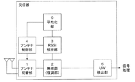
本発明の第1実施形態によるアンテナ切り替え受信システムについて図面を参照して説明する。図1はアンテナ切り替え受信システムの概略構成を示している。アンテナ切り替え受信システムは、2本のアンテナが接続されたアンテナ切替部1と、無線部(復調部)2と、RSSI検出部3と、アンテナ制御部4と、ユニークワード検出部(UW検出部)5等によって構成されている。アンテナ切替部1は、アンテナ制御部4から入力された制御信号に応じて、無線信号を受信するアンテナを切り替える。以下において、アンテナ切替部1に接続され、切り替えられるアンテナが2本の場合について説明するが、同アンテナは3本以上であってもよい。無線部2は、アンテナ切替部1を介していずれかのアンテナで受信した信号を復調する。RSSI検出部3は、アンテナ切替部1を介していずれかのアンテナで受信した信号のRSSI(受信信号強度)を検出する。アンテナ制御部4は、RSSI検出部3によって検出されたRSSI等に基づいて、無線信号を受信するアンテナを選択し、その旨の制御信号をアンテナ切替部1に出力する。UW検出部5は、アンテナ切替部1を介していずれかのアンテナで受信した信号からユニークワードを検出する。
(First embodiment)
An antenna switching reception system according to a first embodiment of the present invention will be described with reference to the drawings. FIG. 1 shows a schematic configuration of an antenna switching reception system. The antenna switching reception system includes an
図2は、第1実施形態のアンテナ切り替え受信システムの動作を示している。また、図3は、第1実施形態のアンテナ切り替え受信システムにおいて、2つのアンテナ、すなわちアンテナA及びアンテナBを用いて受信される信号と、この信号を受信したときの上記アンテナ切り替え受信システムの動作を示している。特に、当初アンテナAが選択されており、そのアンテナAによってプリアンブル信号を受信する場合の例を示している。図3に示した信号は、本実施形態のアンテナ切り替え受信システムと対応する送信システムから送信される。送信システムからは、プリアンブル信号、テスト1信号、テスト2信号、ユニークワード信号及びペイロード信号が送信される。プリアンブル信号、テスト1信号、テスト2信号、ユニークワード信号及びペイロード信号によって1つのフレームが構成される。プリアンブル信号には、例えば、テスト1信号及びテスト2信号の受信の際に、受信するアンテナをアンテナA又はアンテナBに切り替えるタイミングを検出するためのアンテナ切り替えタイミング検出用信号が含まれる。テスト1信号及びテスト2信号は、ペイロード信号を受信するアンテナを選択するために用いられる。テスト1信号は、当初選択されていたアンテナによって受信され、テスト2信号は、切り替えられたアンテナによって受信される。なお、このテスト信号は、アンテナ切替部1によって切り替えられるアンテナの本数に応じて適宜追加される。ペイロード信号には、例えばヘッダ及び映像や音声並びに気温などのデータ又は各種の制御信号が含まれる。
FIG. 2 shows the operation of the antenna switching reception system of the first embodiment. FIG. 3 shows a signal received using two antennas, that is, antenna A and antenna B in the antenna switching reception system of the first embodiment, and the operation of the antenna switching reception system when receiving this signal. Is shown. In particular, an example in which antenna A is initially selected and a preamble signal is received by the antenna A is shown. The signal shown in FIG. 3 is transmitted from a transmission system corresponding to the antenna switching reception system of this embodiment. From the transmission system, a preamble signal, a
図2、3を参照して、第1実施形態のアンテナ切り替え受信システムの動作について説明する。まず、RSSI検出部3が常時、RSSI値を観測し(#1)、RSSIのレベルが瞬間的に又は所定時間以上継続して閾値以上であることを検出するとプリアンブルが入力されたと判断する(#2においてYES)。そして、アンテナ制御部4が現在選択されているアンテナの受信レベルを測定し(#3)、保存する(#4)。図3においては、アンテナAによってテスト1信号が受信され、受信レベルが検出される。そして、アンテナ制御部4がアンテナ切替部1にアンテナを切り替えさせ、アンテナの受信レベルを測定し(#5)、保存する(#6)。図3においては、アンテナBによってテスト2信号が受信され、受信レベルが検出される(アンテナBが当初選択されている場合は、アンテナBによってテスト1信号が受信され、アンテナAによってテスト2信号が受信される)。なお、#3及び#5における受信レベルの測定は、RSSIによるものに限られない。例えば、受信信号を自動利得制御回路によって増幅する際の増幅率から受信レベルを測定する構成であってもよい。
The operation of the antenna switching reception system according to the first embodiment will be described with reference to FIGS. First, the
その後、アンテナ制御部4は、保存した2つの受信レベルを比較する(#7)。アンテナAの受信レベルが大きいときは(#8においてYES)、アンテナ制御部4は、ペイロード信号を受信するためのアンテナとしてアンテナAを選択する。そして、アンテナ切替部1を制御してアンテナAに固定して(#9)、ユニークワード及びペイロード信号を順次受信する(#11)。図3に示す例は、この場合に相当する。アンテナBの受信レベルが大きいときは(#8においてNO)、アンテナ制御部4は、ペイロード信号を受信するためのアンテナとしてアンテナBを選択する。そして、アンテナ切替部1を制御してアンテナBに固定して(#10)、ユニークワード及びペイロード信号を順次受信する(#11)。なお、アンテナAの受信レベルとアンテナBの受信レベルが同等である場合も(#8においてNO)、アンテナの切替を行うことなく(最後にテスト信号を受信したアンテナBに固定して(#10))、ユニークワード等を受信する(#11)。
Thereafter, the
第1実施形態のアンテナ切り替え受信システムによれば、ペイロード信号を受信する前に、各アンテナでテスト信号を受信してペイロード信号を受信するアンテナを選択するので、簡素な構成でマルチパスフェージングによるレベル変動の影響を低減できる。これにより、マルチパス環境下においてもマルチパスフェージングに起因した受信レベルの劣化によるエラー発生を回避できる。また、再送回数を減らしてよりリアルタイムに近い伝送を実現することができる。また、再送が不要な場合にあっては、再送機能を無くして、低コスト化及び小型化に貢献することもできる。 According to the antenna switching reception system of the first embodiment, before receiving a payload signal, each antenna receives a test signal and selects an antenna that receives the payload signal. The influence of fluctuation can be reduced. Thereby, even in a multipath environment, it is possible to avoid the occurrence of errors due to reception level deterioration due to multipath fading. Further, near real-time transmission can be realized by reducing the number of retransmissions. Further, when retransmission is unnecessary, it is possible to eliminate the retransmission function and contribute to cost reduction and size reduction.
また、RSSIのレベルが瞬間的に又は所定時間以上継続して閾値以上となったことをきっかけとして、アンテナを切り替えながらテスト信号を受信する。これにより、アンテナ切り替えを判断するために受信するテスト信号に受信レベルを検出するタイミングを合わせることができる。従って、それぞれのアンテナでテスト信号からより正確に受信レベルを検出して、ペイロード信号を受信するアンテナの選択を適格に行えるようになる。また、アンテナの受信レベルをテスト信号の受信レベル検出のトリガとしているので、迅速にテスト信号の受信レベルの検出に移行することができる。また、それぞれのアンテナで受信したテスト信号のRSSIレベルすなわち受信レベルに基づいて、ペイロード信号を受信するアンテナを選択するので、受信状態の良好なアンテナを精度良く選択することができる。なお、#2において、プリアンブル信号の入力を閾値以上のレベルのRSSIの検出によって行っているが、他の手法、例えば上述した自動利得制御回路の増幅率によって選択されているアンテナの受信レベルを検出し、閾値を比較するように構成してもよい。 In addition, the test signal is received while switching the antenna, triggered by the fact that the RSSI level is instantaneously or continuously longer than a predetermined time and is equal to or higher than the threshold value. Thereby, the timing which detects a reception level can be united with the test signal received in order to judge antenna switching. Therefore, the reception level can be detected more accurately from the test signal at each antenna, and the antenna for receiving the payload signal can be properly selected. In addition, since the reception level of the antenna is used as a trigger for detecting the reception level of the test signal, it is possible to quickly shift to detection of the reception level of the test signal. Further, since the antenna that receives the payload signal is selected based on the RSSI level of the test signal received by each antenna, that is, the reception level, it is possible to accurately select an antenna that has a good reception state. In # 2, the preamble signal is input by detecting RSSI at a level equal to or higher than the threshold. However, the reception level of the antenna selected by another method, for example, the amplification factor of the automatic gain control circuit described above is detected. Alternatively, the threshold values may be compared.
(第2実施形態)
本発明の第2実施形態によるアンテナ切り替え受信システムについて説明する。図4は第2実施形態のアンテナ切り替え受信システムの概略構成を示している。第2実施形態のアンテナ切り替え受信システムは、第1実施形態のアンテナ切り替え受信システムの構成に、プリアンブル検出部6を追加して構成されている。プリアンブル検出部6は、無線部2によって復調された信号からプリアンブル信号を検出する。
(Second Embodiment)
An antenna switching reception system according to the second embodiment of the present invention will be described. FIG. 4 shows a schematic configuration of the antenna switching reception system of the second embodiment. The antenna switching reception system of the second embodiment is configured by adding a
上記第1実施形態のアンテナ切り替え受信システムにおいては、RSSIのレベルが閾値以上であることを検出するとプリアンブル信号が入力されたと判断していた。これに対して、第2実施形態のアンテナ切り替え受信システムにおいては、プリアンブル検出部6は、無線部2によって復調された信号からプリアンブル信号を検出するように構成されている。
In the antenna switching reception system of the first embodiment, it is determined that a preamble signal is input when it is detected that the RSSI level is equal to or higher than a threshold value. On the other hand, in the antenna switching reception system of the second embodiment, the
送信システムから送信されるプリアンブル信号には、テスト1信号及びテスト2信号の受信の際に、アンテナを切り替えるタイミングを検出するためのアンテナ切り替えタイミング検出用信号が含まれている。アンテナ切り替えタイミング検出用信号は、例えば、少なくとも1つのシンボルに相当する所定時間以上に亘って同一の符号が繰り返される信号によって構成される。プリアンブル検出部6は、少なくとも1つのシンボルに相当する所定時間以上に亘って同一の符号が繰り返される信号を検出したとき、アンテナ切り替えタイミング検出用信号すなわちプリアンブル信号を検出したと判断できる。そして、このアンテナ切り替えタイミング検出用信号に基づいて、アンテナAによってテスト1信号又はテスト2信号を、アンテナBによってテスト2信号又はテスト1信号をそれぞれ受信することができる。
The preamble signal transmitted from the transmission system includes an antenna switching timing detection signal for detecting the antenna switching timing when receiving the
図5は、第2実施形態のアンテナ切り替え受信システムの動作を示している。また、図6は、第2実施形態のアンテナ切り替え受信システムにおいて、アンテナA及びアンテナBを用いて受信される信号と、この信号を受信したときの上記アンテナ切り替え受信システムの動作を示している。特に、当初アンテナAが選択されており、そのアンテナAによってプリアンブル信号を受信する場合の例を示している。 FIG. 5 shows the operation of the antenna switching reception system of the second embodiment. FIG. 6 shows a signal received using the antenna A and the antenna B in the antenna switching reception system according to the second embodiment, and an operation of the antenna switching reception system when the signal is received. In particular, an example in which antenna A is initially selected and a preamble signal is received by the antenna A is shown.
図5、6を参照して、第2実施形態のアンテナ切り替え受信システムの動作について説明する。第2実施形態のアンテナ切り替え受信システムにおいては、第1実施形態のアンテナ切り替え受信システムにおける#1、#2の処理に替えて、プリアンブル検出部6によるプリアンブル信号の検出がなされる(#21)。プリアンブル検出部6によってプリアンブル信号が検出されると(#21においてYES)、アンテナ制御部4が現在選択されているアンテナの受信レベルを測定し(#3)、保存する(#4)。図6においては、アンテナAによってテスト1信号が受信され、受信レベルが検出される。以降の動作は、図2及び図3に示した第1実施形態のアンテナ切り替え受信システムの動作と同様である。
The operation of the antenna switching reception system according to the second embodiment will be described with reference to FIGS. In the antenna switching reception system of the second embodiment, the preamble signal is detected by the
第2実施形態のアンテナ切り替え受信システムによれば、テスト信号の前に受信したプリアンブル信号に基づいてテスト信号を受信するアンテナを切り替える。これにより、アンテナ切り替えを判断するために受信するテスト信号に受信レベルを検出するタイミングを合わせることができる。従って、それぞれのアンテナでテスト信号からより正確に受信レベルを検出して、ペイロード信号を受信するアンテナの選択を適格に行えるようになる。また、アンテナ切り替えタイミング検出用信号として、少なくとも1つのシンボルに相当する所定時間以上に亘って同一の符号が繰り返される信号が用いられる。これにより、アンテナ切り替えタイミング検出用信号をノイズと区別して検出できるようになる。 According to the antenna switching reception system of the second embodiment, the antenna that receives the test signal is switched based on the preamble signal received before the test signal. Thereby, the timing which detects a reception level can be united with the test signal received in order to judge antenna switching. Therefore, the reception level can be detected more accurately from the test signal at each antenna, and the antenna for receiving the payload signal can be properly selected. In addition, as the antenna switching timing detection signal, a signal in which the same code is repeated over a predetermined time corresponding to at least one symbol is used. As a result, the antenna switching timing detection signal can be detected separately from noise.
(第3実施形態)
本発明の第3実施形態によるアンテナ切り替え受信システムについて説明する。図7は第3実施形態のアンテナ切り替え受信システムの概略構成を示している。第3実施形態のアンテナ切り替え受信システムは、第2実施形態のアンテナ切り替え受信システムの構成に、スリープ解除部7を追加して構成されている。第3実施形態のアンテナ切り替え受信システムは、消費電力の低いスリープモードと通常の受信モードで動作する。スリープモードから通常の受信モードへの移行は、スリープ解除部7によって制御される。
(Third embodiment)
An antenna switching reception system according to a third embodiment of the present invention will be described. FIG. 7 shows a schematic configuration of the antenna switching reception system of the third embodiment. The antenna switching reception system according to the third embodiment is configured by adding a
図8は、第3実施形態のアンテナ切り替え受信システムの動作を示している。また、図9は、第3実施形態のアンテナ切り替え受信システムにおいて、アンテナA及びアンテナBを用いて受信される信号と、この信号を受信したときの上記アンテナ切り替え受信システムの動作を示している。特に、当初アンテナAが選択されており、そのアンテナAによってプリアンブル信号を受信する場合の例を示している。またプリアンブル信号として、スリープモードを解除するためのプリアンブル1信号と、アンテナを切り替えるタイミングを検出するためのプリアンブル2信号が送信される。なお、プリアンブル1信号又はプリアンブル2信号には、スリープモードから通常の受信モードに移行するのに十分な時間が設定されている。
FIG. 8 shows the operation of the antenna switching reception system of the third embodiment. FIG. 9 shows a signal received using the antenna A and the antenna B in the antenna switching reception system according to the third embodiment, and an operation of the antenna switching reception system when the signal is received. In particular, an example in which antenna A is initially selected and a preamble signal is received by the antenna A is shown. Also, as a preamble signal, a
図8、9を参照して、第3実施形態のアンテナ切り替え受信システムの動作について説明する。第3実施形態のアンテナ切り替え受信システムにおいては、第1実施形態のアンテナ切り替え受信システムにおける#2の処理と#3の処理の間に、#20乃至#23の処理が挿入される。#2において、RSSIのレベルが瞬間的に又は所定時間以上継続して閾値以上であることを検出するとフレームの先頭が入力されたと判断し(#2においてYES)、スリープ解除部7がスリープモードを解除し、通常の受信モードに移行する(#20)。
The operation of the antenna switching reception system according to the third embodiment will be described with reference to FIGS. In the antenna switching reception system according to the third embodiment, processes # 20 to # 23 are inserted between the
プリアンブル検出部6によるプリアンブル信号が検出されると(#21においてYES)、アンテナ制御部4が現在選択されているアンテナの受信レベルを測定し(#3)、保存する(#4)。図9においては、アンテナAによってテスト1信号が受信され、受信レベルが検出される。以下、図2及び図3に示した第1実施形態のアンテナ切り替え受信システムの動作と同様である。#21において直ちにプリアンブル信号が検出されない場合であっても、一定時間が経過するまでは、プリアンブル検出部6によってプリアンブル信号の検出が継続される(#21においてNO、#22においてNO)。一定時間が経過するまでにプリアンブル検出部6によってプリアンブル信号が検出されない場合は(#22においてYES)、再びスリープモードに移行する(#23)。
When the preamble signal is detected by the preamble detector 6 (YES in # 21), the
第3実施形態のアンテナ切り替え受信システムによれば、RSSIのレベルが瞬間的に又は所定時間以上継続して閾値以上となったことをきっかけとしてスリープモードを解除し、選択されているアンテナでアンテナ切り替えタイミング検出用信号を受信する。これにより、アンテナの受信レベルが所定レベル以上になるまで、アンテナ切り替えタイミング検出用信号の受信を開始させずに待機させ、アンテナ切り替え受信システムの消費電力の低減を図ることができる。 According to the antenna switching receiving system of the third embodiment, the sleep mode is canceled in response to the RSSI level instantaneously or continuously exceeding a predetermined time for a predetermined time or more, and the antenna switching is performed with the selected antenna. A timing detection signal is received. Thereby, it is possible to stand by without starting reception of the antenna switching timing detection signal until the antenna reception level becomes equal to or higher than a predetermined level, thereby reducing the power consumption of the antenna switching reception system.
(第4実施形態)
本発明の第4実施形態によるアンテナ切り替え受信システムについて説明する。図10は第4実施形態のアンテナ切り替え受信システムの概略構成を示している。第4実施形態のアンテナ切り替え受信システムは、第2実施形態のアンテナ切り替え受信システムの構成におけるプリアンブル検出部6に替えて低速プリアンブル検出部8が設けられている。低速プリアンブル検出部8は、ペイロード信号と比較して、低い伝送速度で送信されたプリアンブル信号を検出するように構成されている。
(Fourth embodiment)
An antenna switching reception system according to a fourth embodiment of the present invention will be described. FIG. 10 shows a schematic configuration of the antenna switching reception system of the fourth embodiment. The antenna switching reception system according to the fourth embodiment is provided with a low-speed
図11は、第4実施形態のアンテナ切り替え受信システムの動作を示している。第4実施形態のアンテナ切り替え受信システムにおいては、第2実施形態のアンテナ切り替え受信システムにおける#21の処理に替えて、#25の処理が実行される。すなわち、低速プリアンブル検出部8によって低速のプリアンブル信号が検出されると(#25においてYES)、アンテナ制御部4が現在選択されているアンテナの受信レベルを測定し(#3)、保存する(#4)。以降の動作は、図5に示した第2実施形態のアンテナ切り替え受信システムの動作と同様である。
FIG. 11 shows the operation of the antenna switching reception system of the fourth embodiment. In the antenna switching receiving system of the fourth embodiment, the process of # 25 is executed instead of the process of # 21 in the antenna switching receiving system of the second embodiment. That is, when a low-speed preamble signal is detected by the low-speed preamble detection unit 8 (YES in # 25), the
第4実施形態のアンテナ切り替え受信システムによれば、ペイロード信号と比較して低い伝送速度で送信されたプリアンブル信号を受信する。マルチパスフェージング等の通信環境の劣化に起因する受信レベル劣化の影響を受けたアンテナが選択されている場合であっても、もれなくプリアンブル信号を検出できるようになる。従って、それぞれのアンテナでテスト信号からより正確に受信レベルを検出して、ペイロード信号を受信するアンテナの選択を適格に行えるようになる。例えば、当初選択されたアンテナがマルチパスフェージングに起因するレベル劣化の影響を受けていても、上記影響がより少ないアンテナでペイロードを受信できる。これにより、マルチパスフェージングに起因するレベル劣化の影響による受信エラーを回避することができる。 According to the antenna switching reception system of the fourth embodiment, the preamble signal transmitted at a lower transmission rate than the payload signal is received. Even when an antenna affected by reception level deterioration due to deterioration of the communication environment such as multipath fading is selected, it is possible to detect the preamble signal without fail. Therefore, the reception level can be detected more accurately from the test signal at each antenna, and the antenna for receiving the payload signal can be properly selected. For example, even if the initially selected antenna is affected by level degradation caused by multipath fading, the payload can be received by an antenna with less influence. As a result, it is possible to avoid a reception error due to the level deterioration due to multipath fading.
(第5実施形態)
本発明の第5実施形態によるアンテナ切り替え受信システムについて説明する。図12は第5実施形態のアンテナ切り替え受信システムの概略構成を示している。第5実施形態のアンテナ切り替え受信システムは、第1実施形態のアンテナ切り替え受信システムの構成に平均化部9を追加して構成されている。また、第5実施形態のアンテナ切り替え受信システムにおいて、RSSI検出部3は、各アンテナで受信したテスト1信号及びテスト2信号について、RSSIを複数回検出する。平均化部9は、RSSI検出部3によって複数回検出されたRSSIを各アンテナ毎に平均化する。
(Fifth embodiment)
An antenna switching reception system according to a fifth embodiment of the present invention will be described. FIG. 12 shows a schematic configuration of the antenna switching reception system of the fifth embodiment. The antenna switching reception system of the fifth embodiment is configured by adding an
図13は、第5実施形態のアンテナ切り替え受信システムにおいて、アンテナA及びアンテナBを用いて受信される信号と、この信号を受信したときの上記アンテナ切り替え受信システムの動作を示している。特に、当初アンテナAが選択されており、そのアンテナAによってプリアンブル信号を受信する場合の例を示している。アンテナAは、プリアンブル信号に続けてテスト1信号を受信する。アンテナAによるテスト1信号の受信レベルの測定にあたっては、RSSI検出部3によってRSSIが複数回検出され、平均化部9によって平均化された値がアンテナAの受信レベルとされる。その後アンテナが切り替えられ、アンテナBは、テスト2信号を受信する。アンテナBによるテスト2信号の受信レベルの測定にあたっても、RSSI検出部3によってRSSIが複数回検出され、平均化部9によって平均化された値がアンテナBの受信レベルとされる。以降の動作は、第1実施形態のアンテナ切り替え受信システムと同様であるため、その説明を省略する。
FIG. 13 shows a signal received using the antenna A and the antenna B in the antenna switching reception system of the fifth embodiment, and an operation of the antenna switching reception system when the signal is received. In particular, an example in which antenna A is initially selected and a preamble signal is received by the antenna A is shown. Antenna A receives the
第5実施形態のアンテナ切り替え受信システムによれば、受信したテスト信号から複数回検出したRSSIの平均値に基づいて、ペイロード信号を受信するアンテナを選択する。これにより、テスト信号の受信時に瞬間的に混入したノイズによって誤ったアンテナを選択してしまうことを防止できる。すなわち、突発的なノイズの影響を低減し、アンテナ選択の精度を向上させることができる。 According to the antenna switching reception system of the fifth embodiment, the antenna that receives the payload signal is selected based on the average value of RSSI detected a plurality of times from the received test signal. As a result, it is possible to prevent the wrong antenna from being selected due to noise instantaneously mixed when the test signal is received. That is, the influence of sudden noise can be reduced and the accuracy of antenna selection can be improved.
(第6実施形態)
本発明の第6実施形態によるアンテナ切り替え受信システムについて説明する。第6実施形態によるアンテナ切り替え受信システムの構成は、図1に示した第1実施形態によるアンテナ切り替え受信システムと同等である。
(Sixth embodiment)
An antenna switching reception system according to the sixth embodiment of the present invention will be described. The configuration of the antenna switching receiving system according to the sixth embodiment is the same as that of the antenna switching receiving system according to the first embodiment shown in FIG.
図14は、第6実施形態のアンテナ切り替え受信システムにおいて、アンテナA及びアンテナBを用いて受信される信号と、この信号を受信したときの上記アンテナ切り替え受信システムの動作を示している。特に、当初アンテナAが選択されており、そのアンテナAによってプリアンブル信号を受信する場合の例を示している。第6実施形態のアンテナ切り替え受信システムにおいて、送信システムから送信される信号は、テスト1信号が省かれ、プリアンブル信号、テスト2信号、ユニークワード信号及びペイロード信号等によって構成される。
FIG. 14 shows a signal received using the antenna A and the antenna B in the antenna switching reception system of the sixth embodiment, and an operation of the antenna switching reception system when the signal is received. In particular, an example in which antenna A is initially selected and a preamble signal is received by the antenna A is shown. In the antenna switching reception system of the sixth embodiment, the signal transmitted from the transmission system is configured by a preamble signal, a
第6実施形態においては、アンテナAによってプリアンブル信号が受信され、RSSI検出部3によって所定の閾値以上のRSSIが検出されると、アンテナ制御部4は、その値をアンテナAによるテスト信号の受信レベルとして保存する。そして、アンテナBに切り替えてテスト2信号の受信レベルの測定を開始する。以降の動作は、第1実施形態のアンテナ切り替え受信システムと同様であるため、その説明を省略する。なお、本実施形態においては、図14に示す所定の閾値以上のRSSIの検出に替えて、第2実施形態等に示す手法によってプリアンブル信号を検出し、そのときのRSSIの値をアンテナAによるテスト信号の受信レベルとして保存してもよい。
In the sixth embodiment, when the preamble signal is received by the antenna A, and the
第6実施形態のアンテナ切り替え受信システムによれば、テスト信号を受信する前に選択されているアンテナで受信したプリアンブル信号の受信レベルを、そのアンテナによるテスト信号の受信レベルとする。これにより、プリアンブル信号を受信したアンテナに対するテスト信号の送信を不要とすることができ、通信のパケット長を短くして伝送効率の向上を図ることができる。 According to the antenna switching reception system of the sixth embodiment, the reception level of the preamble signal received by the antenna selected before receiving the test signal is set as the reception level of the test signal by the antenna. As a result, transmission of the test signal to the antenna that has received the preamble signal can be made unnecessary, and the communication packet length can be shortened to improve the transmission efficiency.
(第7実施形態)
本発明の第7実施形態によるアンテナ切り替え受信システムについて説明する。図15は第7実施形態のアンテナ切り替え受信システムの概略構成を示している。第7実施形態のアンテナ切り替え受信システムは、第1実施形態のアンテナ切り替え受信システムの構成にアンテナ切替カウンタ部10を追加して構成されている。
(Seventh embodiment)
An antenna switching receiving system according to a seventh embodiment of the present invention will be described. FIG. 15 shows a schematic configuration of the antenna switching reception system of the seventh embodiment. The antenna switching reception system of the seventh embodiment is configured by adding an antenna switching
実際にアンテナを切り替えるには一定時間が必要であり、切り替え中は受信レベルが不安定となって正確なRSSIを測定できないことがある。そのため、本実施形態のアンテナ切り替え受信システムにおいては、アンテナ切替後の一定時間はRSSIを検出しないように、アンテナ切替カウンタ部10が設けられている。すなわち、アンテナ切替カウンタ部10は、アンテナを切り替えた後、受信した信号の受信レベルが安定するまでの所定時間をカウントする。
A certain time is required to actually switch the antenna. During the switching, the reception level may become unstable, and accurate RSSI may not be measured. Therefore, in the antenna switching reception system of the present embodiment, the antenna switching
図16は、第7実施形態のアンテナ切り替え受信システムにおいて、アンテナA及びアンテナBを用いて受信される信号と、この信号を受信したときの上記アンテナ切り替え受信システムの動作を示している。特に、当初アンテナAが選択されており、そのアンテナAによってプリアンブル信号を受信する場合の例を示している。図16に示す場合、アンテナは、2度に亘って切り替えられる。すなわち、アンテナAによってテスト1信号の受信レベルが検出された後、アンテナBに切り替えられ(1度目)、アンテナBによってテスト2信号の受信レベルが検出された後、より受信レベルの大きいアンテナAに切り替えられる(2度目)。これらのアンテナの切替時に、アンテナ切替カウンタ部10は、カウントを開始する。そして、アンテナ制御部4は、アンテナ切替カウンタ部10が所定時間をカウントするまで(図16において、黒く塗りつぶされた時間)は、受信レベルの検出を行わないようにRSSI検出部3を制御する。
FIG. 16 shows a signal received using the antenna A and the antenna B in the antenna switching reception system according to the seventh embodiment, and an operation of the antenna switching reception system when the signal is received. In particular, an example in which antenna A is initially selected and a preamble signal is received by the antenna A is shown. In the case shown in FIG. 16, the antenna is switched twice. That is, after the reception level of the
第7実施形態のアンテナ切り替え受信システムによれば、アンテナ切り替えカウンタ部10のカウントにより、受信した信号の受信レベルが十分に安定した後、RSSIを検出するように構成されている。これにより、正確なRSSIレベルの検出が可能となり、アンテナ選択の精度をより一層向上させることができる。
The antenna switching reception system according to the seventh embodiment is configured to detect RSSI after the reception level of the received signal is sufficiently stabilized by the count of the antenna switching
(第8実施形態)
本発明の第8実施形態によるアンテナ切り替え受信システムについて説明する。図17は第8実施形態のアンテナ切り替え受信システムの概略構成を示している。第8実施形態のアンテナ切り替え受信システムは、第2実施形態のアンテナ切り替え受信システムの構成からRSSI検出部3を廃し相関値算出部11を追加して構成されている。
(Eighth embodiment)
An antenna switching reception system according to the eighth embodiment of the present invention will be described. FIG. 17 shows a schematic configuration of the antenna switching reception system of the eighth embodiment. The antenna switching reception system of the eighth embodiment is configured by eliminating the
テスト1信号及びテスト2信号は、特定の並びの信号列によって構成されて送信システムから送信され、相関値算出部(記憶部)11は、送信されるテスト1信号及びテスト2信号と同一の並びの信号列を記憶している。相関値算出部11は、記憶している信号列と、無線部2によって復調されたテスト信号の信号列の相関値を算出し、アンテナ制御部4は、相関値算出部11によって算出された相関値に基づいてペイロード信号を受信するアンテナを選択する。
The
図18は、第8実施形態のアンテナ切り替え受信システムの動作を示している。第8実施形態のアンテナ切り替え受信システムにおいては、第2実施形態のアンテナ切り替え受信システムにおける#3乃至#8の処理に替えて、#31乃至#36の処理が実行される。まず、プリアンブル信号が検出されると(#21においてYES)、現在選択されているアンテナによってテスト1信号が受信され、相関値算出部11によって相関値が算出され(#31)、最大相関値が保存される(#32)。相関値の算出は、以下の手順でなされる。すなわち受信された信号が無線部2によって復調されると、相関値算出部11は、記憶している信号列に対して、復調されたテスト信号の信号列を1ビットずつずらしながら両者の一致度を順次数値化することにより、相関値を算出する。
FIG. 18 shows the operation of the antenna switching reception system of the eighth embodiment. In the antenna switching reception system of the eighth embodiment, processes # 31 to # 36 are executed instead of the processes of # 3 to # 8 in the antenna switching reception system of the second embodiment. First, when the preamble signal is detected (YES in # 21), the
一方のアンテナの相関値が算出されると、アンテナ制御部4の制御によってアンテナが切り替えられて、テスト1信号が受信され、相関値算出部11によって相関値が算出され(#33)、最大相関値が保存される(#34)。そして、それぞれのアンテナにおける最大相関値が比較され(#35)、アンテナAの相関値が大きい場合は(#36においてYES)#9に移行し、アンテナAの相関値が大きくない場合は(#36においてNO)#10に移行する。以下、図2に示した第1実施形態のアンテナ切り替え受信システムの動作と同様である。なお、#21の処理に替えて、図11に示した#25の処理を行うものとして構成してもよい。
When the correlation value of one antenna is calculated, the antenna is switched under the control of the
第8実施形態のアンテナ切り替え受信システムによれば、相関値算出部11に記憶されている信号列と、受信したテスト信号の信号列から算出された相関値に基づいてペイロード信号を受信するアンテナを選択する。これにより、テスト信号の受信レベルを検出するための構成(例えば、RSSI検出部3等)を必要とすることなく、ペイロード信号を受信するアンテナを選択することが可能となる。よって、アンテナ切り替え受信システムの構成を簡素かつ安価なものとすることができる。
According to the antenna switching reception system of the eighth embodiment, the antenna that receives the payload signal based on the signal sequence stored in the correlation
(第9実施形態)
本発明の第9実施形態によるアンテナ切り替え受信システムについて説明する。第9実施形態のアンテナ切り替え受信システムの構成は、第1実施形態のアンテナ切り替え受信システムの構成と同等である。
(Ninth embodiment)
An antenna switching receiving system according to the ninth embodiment of the present invention will be described. The configuration of the antenna switching reception system of the ninth embodiment is equivalent to the configuration of the antenna switching reception system of the first embodiment.
図19は第9実施形態のアンテナ切り替え受信システムにおいて、アンテナA及びアンテナBを用いて受信される信号と、この信号を受信したときの上記アンテナ切り替え受信システムの動作を示している。特に、当初アンテナAが選択されており、そのアンテナAによってプリアンブル信号を受信し、アンテナの受信レベルの測定をする長さが2シンボルに相当する場合の例を示している。そして、アンテナA及びアンテナBは、テスト信号を受信する際に、所定時間(図19においては、1/2シンボルに相当する時間)毎に切り替えられる。 FIG. 19 shows a signal received using the antenna A and the antenna B in the antenna switching reception system of the ninth embodiment, and an operation of the antenna switching reception system when receiving this signal. In particular, an example is shown in which the antenna A is initially selected, a preamble signal is received by the antenna A, and the length for measuring the reception level of the antenna corresponds to 2 symbols. The antenna A and the antenna B are switched every predetermined time (a time corresponding to 1/2 symbol in FIG. 19) when receiving the test signal.
まず、アンテナAによってプリアンブル信号が受信されて検出された後、アンテナAでテスト1信号を受信して受信レベルの測定が開始される。アンテナAの受信レベルが測定されて保存されるとアンテナBに切り替えられ、アンテナBでもテスト1信号を受信して受信レベルの測定が開始される。アンテナBの受信レベルが測定されて保存されると再びアンテナAに切り替えられ、アンテナAでテスト2信号を受信して受信レベルの測定が開始される。そして、アンテナAの受信レベルが測定されて保存されると再びアンテナBに切り替えられ、アンテナBでもテスト2信号を受信して受信レベルの測定が測定されて保存される。こうして得られた受信レベルは、各アンテナ毎に平均化され、比較される。
First, after the preamble signal is received and detected by the antenna A, the
第9実施形態のアンテナ切り替え受信システムによれば、それぞれのアンテナは、テスト信号を受信する際に、所定時間毎に交互に切り替えられる。これにより、フェージングの発生等による瞬間的な受信レベルの落ち込み等の変動による誤判断を防いで、アンテナ選択の精度を向上させることができる。なお、アンテナの受信レベルの測定にあたっては、3シンボル以上の長さを用いてもよい。この場合、長時間に亘って受信レベルをより正確に判定することができる。また、アンテナの選択にあたっては、受信レベルの平均値に限られず、第8実施形態のアンテナ切り替え受信システムに係る最大相関値に基づくものとしてもよい。 According to the antenna switching reception system of the ninth embodiment, the respective antennas are alternately switched every predetermined time when receiving the test signal. Thereby, it is possible to prevent erroneous determination due to fluctuations such as a momentary drop in reception level due to the occurrence of fading and the like, and to improve the accuracy of antenna selection. In measuring the reception level of the antenna, a length of 3 symbols or more may be used. In this case, the reception level can be determined more accurately over a long time. Further, the selection of the antenna is not limited to the average value of the reception level, and may be based on the maximum correlation value according to the antenna switching reception system of the eighth embodiment.
(第10実施形態)
本発明の第10実施形態によるアンテナ切り替え受信システムについて説明する。図20は第10実施形態のアンテナ切り替え受信システムの概略構成を示している。第10実施形態のアンテナ切り替え受信システムは、第1実施形態のアンテナ切り替え受信システムの構成に、ペイロード長カウンタ部12を追加して構成されている。ペイロード長カウンタ部12は、ペイロード信号を受信している際には、アンテナの切り替えを行わないように、受信しているパケットのペイロード信号の長さに相当する時間をカウントする。
(10th Embodiment)
An antenna switching receiving system according to the tenth embodiment of the present invention will be described. FIG. 20 shows a schematic configuration of the antenna switching reception system of the tenth embodiment. The antenna switching reception system of the tenth embodiment is configured by adding a payload
図21は、第10実施形態のアンテナ切り替え受信システムにおいて、アンテナA及びアンテナBを用いて受信される信号と、この信号を受信したときの上記アンテナ切り替え受信システムの動作を示している。特に、当初アンテナAが選択されており、そのアンテナAによってプリアンブル信号を受信する場合の例を示している。 FIG. 21 shows a signal received using the antenna A and the antenna B in the antenna switching reception system of the tenth embodiment and the operation of the antenna switching reception system when receiving this signal. In particular, an example in which antenna A is initially selected and a preamble signal is received by the antenna A is shown.
図21において、アンテナ1に固定した後、ユニークワード信号が検出されるまでは、図3に示した第1実施形態のアンテナ切り替え受信システムと同等の動作を行う。ユニークワード信号が検出されると、ペイロード長カウンタ部12は、ペイロード信号の長さに相当する時間のカウントを開始する。そして、一定時間(ペイロードの受信時間)は、アンテナ切替機能(つまりはそのトリガとなるプリアンブル信号(RSSI)の検出)を停止する。
In FIG. 21, after being fixed to the
第10実施形態のアンテナ切り替え受信システムによれば、ペイロード長カウンタ部のカウントによって、ペイロード信号を受信している際にはアンテナの切り替えを行わない。これにより、ペイロード信号の受信中に誤ってアンテナが切り替えられることによって発生する受信エラーを防止できる。 According to the antenna switching reception system of the tenth embodiment, antenna switching is not performed when a payload signal is received based on the count of the payload length counter unit. As a result, it is possible to prevent a reception error that occurs when the antenna is erroneously switched during reception of the payload signal.
(第11実施形態)
本発明の第11実施形態によるアンテナ切り替え受信システムについて説明する。図22は第11実施形態のアンテナ切り替え受信システムの概略構成を示している。第11実施形態のアンテナ切り替え受信システムは、第1実施形態のアンテナ切り替え受信システムの構成に、切替停止閾値設定部13を追加して構成されている。第11実施形態のアンテナ切り替え受信システムにあっては、プリアンブル信号の受信においてアンテナを切り替える必要がないほどに十分に強いRSSIレベルが検出されたとき、アンテナの切り替え機能を停止させる。そこで、切替停止閾値設定部13は、アンテナの切り替え機能を停止させる基準となるRSSIレベルの閾値を設定する際に用いられる。なお、切替停止閾値設定部13によって設定される閾値は、第1実施形態の図2の#2及び図3に記載の閾値よりも大きな値で設定されている。
(Eleventh embodiment)
An antenna switching reception system according to the eleventh embodiment of the present invention will be described. FIG. 22 shows a schematic configuration of the antenna switching receiving system of the eleventh embodiment. The antenna switching reception system of the eleventh embodiment is configured by adding a switching stop
図23は、第11実施形態のアンテナ切り替え受信システムにおいて、アンテナA及びアンテナBを用いて受信される信号と、この信号を受信したときの上記アンテナ切り替え受信システムの動作を示している。特に、当初アンテナAが選択されており、そのアンテナAによってプリアンブル信号を受信する場合の例を示している。図23において、まずプリアンブル信号の受信し、そのRSSIを検出する。このとき、RSSIが切替停止閾値設定部13によって設定される閾値よりも大きい場合は、アンテナの切り替えは行わない。すなわち、引き続きアンテナAによって、テスト1信号、テスト2信号、ユニークワード信号及びペイロード信号が受信される。
FIG. 23 shows a signal received using the antenna A and the antenna B in the antenna switching reception system of the eleventh embodiment and the operation of the antenna switching reception system when receiving this signal. In particular, an example in which antenna A is initially selected and a preamble signal is received by the antenna A is shown. In FIG. 23, first, a preamble signal is received and its RSSI is detected. At this time, when the RSSI is larger than the threshold set by the switching stop
第11実施形態のアンテナ切り替え受信システムによれば、当初選択されているアンテナの受信レベルが所定の閾値以上であるときは、そのアンテナで問題なくペイロード信号を受信できると判断してアンテナの切り替えを行わない。これにより、受信レベルの検出誤差等の発生に伴うアンテナ選択の誤動作の可能性を低減できる。 According to the antenna switching reception system of the eleventh embodiment, when the reception level of the initially selected antenna is equal to or higher than the predetermined threshold, it is determined that the antenna can receive the payload signal without any problem, and the antenna is switched. Not performed. Thereby, it is possible to reduce the possibility of malfunction of antenna selection accompanying the occurrence of reception level detection error or the like.
(第12実施形態)
本発明の第12実施形態によるアンテナ切り替え受信システムについて説明する。図24は第12実施形態のアンテナ切り替え受信システムの概略構成を示している。第12実施形態のアンテナ切り替え受信システムは、第1実施形態のアンテナ切り替え受信システムの構成に、通信周期カウンタ部14を追加して構成されている。無線通信においては、通常、各機器の状態を確認するために各機器間において、例えば数分乃至数時間毎に定期通信が実行される。本第12実施形態は、定期通信の通信可否に応じてアンテナを切り替える。具体的には、選択されているアンテナで定期通信のユニークワードが所定の時間内に検出されなかったとき、他方のアンテナに切り替える。通信周期カウンタ部14は、ユニークワード検出部5によってパケット内のユニークワードが検出されたことをきっかけとして、カウントを開始する。
(Twelfth embodiment)
An antenna switching receiving system according to the twelfth embodiment of the present invention will be described. FIG. 24 shows a schematic configuration of the antenna switching receiving system of the twelfth embodiment. The antenna switching reception system of the twelfth embodiment is configured by adding a communication
図25は、第12実施形態のアンテナ切り替え受信システムにおいて、アンテナA及びアンテナBを用いて受信される信号と、この信号を受信したときの上記アンテナ切り替え受信システムの動作を示している。特に、当初アンテナAが選択されており、そのアンテナAによってプリアンブル信号を受信する場合の例を示している。図25において、送信システムからは、定期通信パケット1、定期通信パケット2、定期通信パケット3、定期通信パケット4...が定期的に送信される。これらの定期通信パケットは、通常のデータ伝送信号や制御信号の合間に適宜送信される。アンテナAによって定期通信パケット1が受信されると、通信周期カウンタ部14は、ユニークワード検出部5によってパケット内のユニークワードが検出されたことをきっかけとして、カウントを開始する。その後アンテナAに故障等が発生すると、通信周期カウンタ部14のカウント値が一定値を超えても、アンテナ切り替え受信システムは、定期通信パケット2を受信できなくなる。このとき、アンテナ制御部4は、アンテナAに故障等が発生した可能性があると判断して、アンテナBに切り替えて、定期通信パケット3以降を受信する。
FIG. 25 shows a signal received using the antenna A and the antenna B in the antenna switching reception system of the twelfth embodiment and the operation of the antenna switching reception system when receiving this signal. In particular, an example in which antenna A is initially selected and a preamble signal is received by the antenna A is shown. 25, from the transmission system, the
第12実施形態のアンテナ切り替え受信システムは、ユニークワード検出部5によってユニークワードが検出された後、通信周期カウンタ部14が所定値をカウントするまでに次の定期通信のユニークワードが受信できなかったとき、別のアンテナに切り替える。これにより、選択されているアンテナに故障等の不具合が発生したことを検知して別のアンテナに切り替えることができるので、受信できない状態が継続してしまうことを防止できる。
In the antenna switching receiving system according to the twelfth embodiment, after the unique word is detected by the
なお、本発明は上記実施形態の構成に限られることなく、少なくともペイロード信号を受信する前に、複数のアンテナでテスト信号を受信してペイロード信号を受信するアンテナを選択するように構成されていればよい。また、上述した各実施形態の特徴を適宜組み合わせたアンテナ切り替え受信システムであってもよい。 Note that the present invention is not limited to the configuration of the above-described embodiment, and at least before receiving a payload signal, the antenna may be configured to receive a test signal with a plurality of antennas and select an antenna that receives the payload signal. That's fine. Moreover, the antenna switching reception system which combined the characteristic of each embodiment mentioned above suitably may be sufficient.
また、本発明は種々の変形が可能であり、例えば、各実施形態において、プリアンブル信号とテスト信号とは、同一の信号列によって構成されていてもよい。この場合にあっては、プリアンブル信号及びテスト信号を単一の構成によって生成することができる。これにより、プリアンブル信号及びテスト信号を生成し送信する送信システムの構成を簡素化することができる。 The present invention can be modified in various ways. For example, in each embodiment, the preamble signal and the test signal may be configured by the same signal sequence. In this case, the preamble signal and the test signal can be generated by a single configuration. Thereby, the structure of the transmission system which produces | generates and transmits a preamble signal and a test signal can be simplified.
また、テスト信号は、ペイロード信号を模した擬似ランダム信号列を含むように構成されていてもよく、さらには、ペイロード信号の中に含まれる一部の信号列と同一の信号列で構成されていてもよい。この場合にあっては、ペイロード信号に近い又は同一の並びの信号列のテスト信号を受信した結果に基づいて、ペイロード信号を受信するアンテナを選択することができる。これにより、アンテナ選択の精度をより一層向上させることができる。 In addition, the test signal may be configured to include a pseudo-random signal sequence that imitates the payload signal, and further includes a signal sequence that is the same as a part of the signal sequence included in the payload signal. May be. In this case, the antenna that receives the payload signal can be selected based on the result of receiving the test signal of the signal sequence close to or identical to the payload signal. Thereby, the accuracy of antenna selection can be further improved.
また、ペイロード信号と同等の伝送速度で送信システムから送信されたテスト信号を受信するように構成することにより、ペイロード信号を実際に受信している状態に近い状態でテスト信号を受信し、アンテナを選択することができる。これにより、アンテナ選択の精度をより一層向上させることができる。また、テスト信号の送受信に要する時間を短縮できる。 In addition, by configuring to receive the test signal transmitted from the transmission system at the same transmission rate as the payload signal, the test signal is received in a state close to the state in which the payload signal is actually received, and the antenna is You can choose. Thereby, the accuracy of antenna selection can be further improved. Further, the time required for transmitting / receiving the test signal can be shortened.
また、第2実施形態及び第8実施形態におけるプリアンブル信号の検出(図5及び図18における#21)は、相関値の算出によって行うように構成されていてもよい。この場合、アンテナ切り替えタイミング検出用信号を含むプリアンブル信号は、特定の並びの信号列によって構成されて送信システムから送信される。プリアンブル検出部(記憶部、相関値算出部)6は、プリアンブル信号と同一の並びの信号列を記憶する。さらにプリアンブル検出部6は、記憶した信号列と、受信したプリアンブル信号の信号列の相関値を算出する。相関値の算出は、以下の手順でなされる。すなわち受信された信号が無線部2によって復調されると、プリアンブル検出部6は、記憶している信号列に対して、復調されたプリアンブル信号の信号列を1ビットずつずらしながら両者の一致度を順次数値化することにより、相関値を算出する。この構成によれば、プリアンブル信号とノイズとをより明確に区別することができ、ノイズに対する耐性を強化することが可能となる。なお、第4実施形態におけるプリアンブル信号の検出(図11における#25)についても、上記と同様である。
The preamble signal detection (# 21 in FIGS. 5 and 18) in the second and eighth embodiments may be configured to be performed by calculating a correlation value. In this case, the preamble signal including the antenna switching timing detection signal is configured by a specific sequence of signal sequences and transmitted from the transmission system. The preamble detection unit (storage unit, correlation value calculation unit) 6 stores a signal sequence in the same sequence as the preamble signal. Further, the
1 アンテナ切替部
2 無線部(復調部)
3 RSSI検出部
4 アンテナ制御部
5 ユニークワード検出部
6 プリアンブル検出部
7 スリープ解除部
8 低速プリアンブル検出部
9 平均化部
10 アンテナ切替カウンタ部
11 相関値算出部
12 ペイロード長カウンタ部
13 切替停止閾値設定部
14 通信周期カウンタ部
1
DESCRIPTION OF
Claims (1)
送信システムからは、プリアンブル信号と、少なくとも1つのテスト信号とペイロード信号がこの順番で送信され、前記プリアンブル信号に含まれるアンテナ切り替えタイミング検出用信号は、前記ペイロード信号と比較して、低い伝送速度で送信され、
選択されているアンテナが受信した信号の受信レベルが瞬間的に又は所定時間以上継続して閾値以上であることを検出すると前記プリアンブル信号が入力されたと判断し、前記アンテナ切り替えタイミング検出用信号を検出し、
前記アンテナ切り替えタイミング検出用信号に基づいて前記複数のアンテナを切り替えて前記少なくとも1つのテスト信号を受信し、
前記アンテナ切り替えタイミング検出用信号及び前記テスト信号は、それぞれ特定の並びの信号列によって構成されて送信されるものであり、
送信される前記アンテナ切り替えタイミング検出用信号及び送信される前記テスト信号と同一の並びの信号列を記憶する記憶部と、
前記記憶部に記憶されている信号列と、受信した前記アンテナ切り替えタイミング検出用信号の信号列の相関値、及び受信した前記テスト信号の信号列の相関値を算出する相関値算出部を有し、
前記アンテナ切り替えタイミング検出用信号を前記相関値算出部によって算出された相関値に基づいて検出し、
前記相関値算出部によって算出された受信した前記テスト信号の信号列の相関値に基づいて前記ペイロード信号を受信するアンテナを選択することを特徴とするアンテナ切り替え受信システム。 In an antenna switching reception system that receives a radio signal by switching a plurality of antennas,
From the transmission system, a preamble signal, at least one test signal, and a payload signal are transmitted in this order, and the antenna switching timing detection signal included in the preamble signal is transmitted at a lower transmission rate than the payload signal. Sent
It determines that detects that the reception level of the received antennas selected signal is momentarily or continuously for a threshold or more than a predetermined time and the preamble signal is input, detects the antenna switching timing detection signal And
Receiving the at least one test signal by switching the plurality of antennas based on the antenna switching timing detection signal ;
The antenna switching timing detection signal and the test signal are each configured by a specific sequence of signal sequences and transmitted.
A storage unit that stores the same signal sequence as the transmitted antenna switching timing detection signal and the transmitted test signal ;
A correlation value calculation unit that calculates a correlation value between the signal sequence stored in the storage unit, the signal sequence of the received antenna switching timing detection signal , and the correlation value of the signal sequence of the received test signal; ,
Detecting the antenna switching timing detection signal based on the correlation value calculated by the correlation value calculation unit ;
An antenna switching receiving system, wherein an antenna for receiving the payload signal is selected based on a correlation value of a signal sequence of the received test signal calculated by the correlation value calculation unit .
Priority Applications (1)
| Application Number | Priority Date | Filing Date | Title |
|---|---|---|---|
| JP2010153421A JP5842111B2 (en) | 2010-07-05 | 2010-07-05 | Antenna switching reception system |
Applications Claiming Priority (1)
| Application Number | Priority Date | Filing Date | Title |
|---|---|---|---|
| JP2010153421A JP5842111B2 (en) | 2010-07-05 | 2010-07-05 | Antenna switching reception system |
Publications (2)
| Publication Number | Publication Date |
|---|---|
| JP2012015975A JP2012015975A (en) | 2012-01-19 |
| JP5842111B2 true JP5842111B2 (en) | 2016-01-13 |
Family
ID=45601840
Family Applications (1)
| Application Number | Title | Priority Date | Filing Date |
|---|---|---|---|
| JP2010153421A Active JP5842111B2 (en) | 2010-07-05 | 2010-07-05 | Antenna switching reception system |
Country Status (1)
| Country | Link |
|---|---|
| JP (1) | JP5842111B2 (en) |
Families Citing this family (6)
| Publication number | Priority date | Publication date | Assignee | Title |
|---|---|---|---|---|
| JP6273544B2 (en) * | 2012-03-13 | 2018-02-07 | パナソニックIpマネジメント株式会社 | Wireless communication system |
| JP5979540B2 (en) * | 2012-03-13 | 2016-08-24 | パナソニックIpマネジメント株式会社 | Wireless communication system |
| JP6032543B2 (en) * | 2012-10-19 | 2016-11-30 | パナソニックIpマネジメント株式会社 | Antenna switching reception system and corresponding transmission system |
| JP6032544B2 (en) * | 2012-10-19 | 2016-11-30 | パナソニックIpマネジメント株式会社 | Antenna switching reception system and corresponding transmission system |
| JP6252305B2 (en) * | 2014-03-28 | 2017-12-27 | 富士通株式会社 | Portable terminal device and antenna switching method |
| US11856428B2 (en) * | 2021-07-29 | 2023-12-26 | Hewlett Packard Enterprise Development Lp | Determining antenna condition |
Family Cites Families (9)
| Publication number | Priority date | Publication date | Assignee | Title |
|---|---|---|---|---|
| JPH0771035B2 (en) * | 1990-07-04 | 1995-07-31 | 三菱電機株式会社 | Antenna selection diversity reception system |
| JP3278575B2 (en) * | 1996-05-31 | 2002-04-30 | 沖電気工業株式会社 | Diversity receiver circuit |
| JPH114215A (en) * | 1997-06-11 | 1999-01-06 | Matsushita Electric Ind Co Ltd | Diversity circuit |
| JP4441064B2 (en) * | 2000-05-15 | 2010-03-31 | 株式会社日立国際電気 | Receiving machine |
| JP2002111565A (en) * | 2000-09-28 | 2002-04-12 | Matsushita Electric Ind Co Ltd | Array antenna communication device and radio communication method |
| JP2007529160A (en) * | 2003-10-15 | 2007-10-18 | 松下電器産業株式会社 | Diversity receiving apparatus and radio receiving apparatus using the same |
| JP3873052B2 (en) * | 2003-11-27 | 2007-01-24 | 株式会社東芝 | Wireless communication system and wireless communication apparatus |
| JP2006165922A (en) * | 2004-12-07 | 2006-06-22 | Matsushita Electric Ind Co Ltd | Radio receiver |
| JP4493573B2 (en) * | 2005-09-22 | 2010-06-30 | オリンパス株式会社 | Receiver |
-
2010
- 2010-07-05 JP JP2010153421A patent/JP5842111B2/en active Active
Also Published As
| Publication number | Publication date |
|---|---|
| JP2012015975A (en) | 2012-01-19 |
Similar Documents
| Publication | Publication Date | Title |
|---|---|---|
| JP5842111B2 (en) | Antenna switching reception system | |
| US7400872B2 (en) | Radio receiver for selecting appropriate diversity antennas by comparing correlation values and a method for the same | |
| US7729677B2 (en) | Method of and device for antennae diversity switching | |
| US7146134B2 (en) | Apparatus and method for dynamic diversity based upon receiver-side assessment of link quality | |
| US8417205B2 (en) | Antenna selection scheme for multiple antennae | |
| US8064861B2 (en) | Circuit and method for antenna selection in an antenna diversity receiver | |
| WO2012028917A1 (en) | Antenna-switchable reception system and wireless communications device including same | |
| US20050197086A1 (en) | Diversity control method and wireless communication apparatus | |
| US6505037B1 (en) | Data unit detection including antenna diversity | |
| US20100091742A1 (en) | Correlation method and apparatus for acquiring synchronization in wireless local area network | |
| JP5219278B2 (en) | Diversity communication system and diversity receiver | |
| WO2007110923A1 (en) | Diversity receiver apparatus and diversity reception method | |
| JP5658946B2 (en) | Antenna switching reception system | |
| JP6032645B2 (en) | Antenna switching reception system and corresponding transmission system | |
| JP5193889B2 (en) | Diversity receiver and diversity communication system | |
| JP5747173B2 (en) | Antenna switching reception system | |
| JP5747174B2 (en) | Antenna switching reception system | |
| JP4463029B2 (en) | Fading influence degree calculating device and receiving device | |
| JP4028856B2 (en) | Receiving device, mobile communication terminal, and communication system | |
| JP6032543B2 (en) | Antenna switching reception system and corresponding transmission system | |
| JP5747177B2 (en) | Antenna switching reception system and wireless communication device including the same | |
| JP2003283399A (en) | Radio apparatus | |
| JP6032646B2 (en) | Antenna switching reception system and corresponding transmission system | |
| JP2014086766A (en) | Antenna changeover communication system | |
| JP6032544B2 (en) | Antenna switching reception system and corresponding transmission system |
Legal Events
| Date | Code | Title | Description |
|---|---|---|---|
| A711 | Notification of change in applicant |
Free format text: JAPANESE INTERMEDIATE CODE: A712 Effective date: 20120117 |
|
| A621 | Written request for application examination |
Free format text: JAPANESE INTERMEDIATE CODE: A621 Effective date: 20130619 |
|
| A977 | Report on retrieval |
Free format text: JAPANESE INTERMEDIATE CODE: A971007 Effective date: 20140131 |
|
| A131 | Notification of reasons for refusal |
Free format text: JAPANESE INTERMEDIATE CODE: A131 Effective date: 20140212 |
|
| A521 | Written amendment |
Free format text: JAPANESE INTERMEDIATE CODE: A523 Effective date: 20140402 |
|
| A131 | Notification of reasons for refusal |
Free format text: JAPANESE INTERMEDIATE CODE: A131 Effective date: 20140729 |
|
| A521 | Written amendment |
Free format text: JAPANESE INTERMEDIATE CODE: A523 Effective date: 20140926 |
|
| A711 | Notification of change in applicant |
Free format text: JAPANESE INTERMEDIATE CODE: A711 Effective date: 20141007 |
|
| RD03 | Notification of appointment of power of attorney |
Free format text: JAPANESE INTERMEDIATE CODE: A7423 Effective date: 20141023 |
|
| A02 | Decision of refusal |
Free format text: JAPANESE INTERMEDIATE CODE: A02 Effective date: 20150127 |
|
| A521 | Written amendment |
Free format text: JAPANESE INTERMEDIATE CODE: A523 Effective date: 20150410 |
|
| A911 | Transfer of reconsideration by examiner before appeal (zenchi) |
Free format text: JAPANESE INTERMEDIATE CODE: A911 Effective date: 20150420 |
|
| TRDD | Decision of grant or rejection written | ||
| A01 | Written decision to grant a patent or to grant a registration (utility model) |
Free format text: JAPANESE INTERMEDIATE CODE: A01 Effective date: 20150602 |
|
| A61 | First payment of annual fees (during grant procedure) |
Free format text: JAPANESE INTERMEDIATE CODE: A61 Effective date: 20150625 |
|
| R151 | Written notification of patent or utility model registration |
Ref document number: 5842111 Country of ref document: JP Free format text: JAPANESE INTERMEDIATE CODE: R151 |