JP5841714B2 - Tactile sensation presentation apparatus and control method for tactile sensation presentation apparatus - Google Patents
Tactile sensation presentation apparatus and control method for tactile sensation presentation apparatus Download PDFInfo
- Publication number
- JP5841714B2 JP5841714B2 JP2010168582A JP2010168582A JP5841714B2 JP 5841714 B2 JP5841714 B2 JP 5841714B2 JP 2010168582 A JP2010168582 A JP 2010168582A JP 2010168582 A JP2010168582 A JP 2010168582A JP 5841714 B2 JP5841714 B2 JP 5841714B2
- Authority
- JP
- Japan
- Prior art keywords
- tactile sensation
- control unit
- pressing load
- sensation presentation
- unit
- Prior art date
- Legal status (The legal status is an assumption and is not a legal conclusion. Google has not performed a legal analysis and makes no representation as to the accuracy of the status listed.)
- Active
Links
Images


Classifications
-
- G—PHYSICS
- G06—COMPUTING; CALCULATING OR COUNTING
- G06F—ELECTRIC DIGITAL DATA PROCESSING
- G06F3/00—Input arrangements for transferring data to be processed into a form capable of being handled by the computer; Output arrangements for transferring data from processing unit to output unit, e.g. interface arrangements
- G06F3/01—Input arrangements or combined input and output arrangements for interaction between user and computer
- G06F3/016—Input arrangements with force or tactile feedback as computer generated output to the user
-
- G—PHYSICS
- G06—COMPUTING; CALCULATING OR COUNTING
- G06F—ELECTRIC DIGITAL DATA PROCESSING
- G06F3/00—Input arrangements for transferring data to be processed into a form capable of being handled by the computer; Output arrangements for transferring data from processing unit to output unit, e.g. interface arrangements
- G06F3/01—Input arrangements or combined input and output arrangements for interaction between user and computer
- G06F3/03—Arrangements for converting the position or the displacement of a member into a coded form
- G06F3/033—Pointing devices displaced or positioned by the user, e.g. mice, trackballs, pens or joysticks; Accessories therefor
- G06F3/0354—Pointing devices displaced or positioned by the user, e.g. mice, trackballs, pens or joysticks; Accessories therefor with detection of 2D relative movements between the device, or an operating part thereof, and a plane or surface, e.g. 2D mice, trackballs, pens or pucks
- G06F3/03547—Touch pads, in which fingers can move on a surface
-
- G—PHYSICS
- G06—COMPUTING; CALCULATING OR COUNTING
- G06F—ELECTRIC DIGITAL DATA PROCESSING
- G06F3/00—Input arrangements for transferring data to be processed into a form capable of being handled by the computer; Output arrangements for transferring data from processing unit to output unit, e.g. interface arrangements
- G06F3/01—Input arrangements or combined input and output arrangements for interaction between user and computer
- G06F3/03—Arrangements for converting the position or the displacement of a member into a coded form
- G06F3/041—Digitisers, e.g. for touch screens or touch pads, characterised by the transducing means
-
- G—PHYSICS
- G06—COMPUTING; CALCULATING OR COUNTING
- G06F—ELECTRIC DIGITAL DATA PROCESSING
- G06F2203/00—Indexing scheme relating to G06F3/00 - G06F3/048
- G06F2203/041—Indexing scheme relating to G06F3/041 - G06F3/045
- G06F2203/04105—Pressure sensors for measuring the pressure or force exerted on the touch surface without providing the touch position
Description
本発明は、タッチセンサを備える触感呈示装置及び当該触感呈示装置の制御方法に関するものである。 The present invention relates to a tactile sensation providing apparatus including a touch sensor and a control method of the tactile sensation providing apparatus.
近年、携帯電話やゲーム機等の携帯機器、電卓、券売機等の情報機器、電子レンジ、テレビ、照明器具等の家電製品、産業用機器(FA機器)等には、操作者による入力操作を受け付ける操作部等の入力装置として、タッチパネルやタッチスイッチ等のタッチセンサを備える入力装置が広く使用されている。 In recent years, input operations by operators have been applied to mobile devices such as mobile phones and game machines, information devices such as calculators and ticket vending machines, home appliances such as microwave ovens, televisions, and lighting equipment, and industrial equipment (FA devices). 2. Description of the Related Art Input devices including touch sensors such as a touch panel and a touch switch are widely used as input devices such as an operation unit to receive.
タッチセンサには、抵抗膜方式、静電容量方式、光学式等の種々の方式が知られている。しかし、いずれの方式のタッチセンサにおいても、指やスタイラスペン等の押下対象(オブジェクト)によるタッチ入力(入力操作)を受け付けるものであって、タッチセンサ自体は、タッチされても、押しボタンスイッチのようには物理的に変位しない。 Various types of touch sensors such as a resistive film type, a capacitance type, and an optical type are known. However, any type of touch sensor accepts a touch input (input operation) by an object to be pressed (object) such as a finger or a stylus pen. Does not physically displace.
そこで、例えば、タッチセンサの所定領域への所定の押下荷重以上の入力を検出し、これによりタッチセンサを振動させて、操作者の指先に触覚をフィードバックする入力装置が提案されている(例えば、特許文献1参照)。 Thus, for example, an input device has been proposed that detects an input greater than a predetermined pressing load on a predetermined area of the touch sensor, vibrates the touch sensor, and feeds back a tactile sensation to the fingertip of the operator (for example, Patent Document 1).
タッチセンサを振動させる触感呈示の機能は、専用のプロセッサや圧電素子などを用いたチップとして実装することができる。例えば、触感呈示機能を持たないタッチセンサ装置に触感呈示機能を提供するチップを組み合わせることができれば、種々のタッチセンサ装置に触感呈示機能を導入し、触感呈示装置として機能させることが可能になる。この場合、触感呈示装置は、アプリケーションやタッチセンサなどの装置全体を制御するチップと、触感呈示を制御するチップとを備えるデュアルチップ構成となる。しかし、従来技術においては、デュアルチップ構成の触感呈示装置に関する検討が行われていない。 The tactile sensation providing function for vibrating the touch sensor can be implemented as a chip using a dedicated processor, a piezoelectric element, or the like. For example, if a touch sensor device that does not have a tactile sensation providing function can be combined with a chip that provides the tactile sensation providing function, the tactile sensation providing function can be introduced into various touch sensor devices and function as a tactile sensation providing device. In this case, the tactile sensation providing apparatus has a dual chip configuration including a chip that controls the entire apparatus such as an application and a touch sensor, and a chip that controls tactile sensation presentation. However, the conventional technology has not been studied on a tactile sensation providing device having a dual chip configuration.
従来のタッチセンサは、タッチ入力の位置情報を検出するが、タッチ入力の押下荷重の検出は行わない。一方、触感呈示用のチップは、所定値以上の押下荷重があった場合に触感を呈示するという制御を行うため、例えば圧電素子等によりタッチ入力の押下荷重を検出する。このため、アプリケーションなど装置全体を制御するチップが押下荷重に基づいてアプリケーションの処理を行うためには、触感呈示用のチップから押下荷重を取得しなくてはならない。例えば、押しボタンやアイコンなど、アプリケーションのユーザインタフェースのうち、押下荷重に対応した処理を行うべき所定領域(押下荷重対応エリア)に所定の押下荷重以上のタッチ入力がある場合、当該タッチ入力に対して適切なアプリケーション処理を行うことが期待される。しかし、触感呈示用のチップが検出する押下荷重は、触感呈示の制御のために検出された情報であって、他のチップでのアプリケーション処理への応用は検討されていない。 A conventional touch sensor detects position information of a touch input, but does not detect a pressing load of the touch input. On the other hand, the tactile sensation providing chip detects the touch input pressing load using, for example, a piezoelectric element or the like in order to perform a control of presenting a tactile sensation when there is a pressing load of a predetermined value or more. For this reason, in order for a chip that controls the entire apparatus, such as an application, to perform application processing based on the pressing load, the pressing load must be acquired from the tactile sense presentation chip. For example, when there is a touch input exceeding a predetermined pressing load in a predetermined area (a pressing load corresponding area) in the application user interface, such as a push button or an icon, where processing corresponding to the pressing load is to be performed, It is expected to perform appropriate application processing. However, the pressing load detected by the tactile sensation providing chip is information detected for controlling the tactile sensation presentation, and application to application processing using other chips has not been studied.
したがって、かかる事情に鑑みてなされた本発明の目的は、デュアルチップ間で、触感呈示のために検出された押下荷重に関する信号を交換することにより、押下荷重に基づくアプリケーション処理を実行可能な触感呈示装置を提供することにある。 Accordingly, an object of the present invention made in view of such circumstances is to provide a tactile sensation capable of executing application processing based on a pressing load by exchanging signals regarding the pressing load detected for the tactile sensation between the dual chips. To provide an apparatus.
上記目的を達成する第1の観点に係る触感呈示装置の発明は、
タッチセンサと、
触感呈示のために該タッチセンサに対する押下荷重を検出する荷重検出部と、
前記タッチセンサのタッチ面を振動させる触感呈示部と、
該触感呈示部の駆動を制御する触感呈示制御部と、
押下荷重に対応した処理を行うアプリケーションを制御する主制御部と、を備え、
前記主制御部は、前記アプリケーション起動時に前記触感呈示制御部に押下荷重検出指示を送信し、アプリケーション終了時に前記触感呈示制御部に押下荷重停止指示を送信し、
前記触感呈示制御部は、前記主制御部から前記押下荷重検出指示を受けると、前記押下荷重の検出を開始し、前記主制御部から前記押下荷重停止指示を受けると、前記押下荷重の検出を停止する、ことを特徴とするものである。
The invention of the tactile sensation providing apparatus according to the first aspect to achieve the above object is as follows:
A touch sensor;
A load detection unit for detecting a pressing load on the touch sensor for tactile sensation presentation;
A tactile sensation providing unit that vibrates the touch surface of the touch sensor;
A tactile sensation presentation control unit that controls driving of the tactile sensation presentation unit;
A main control unit that controls an application that performs processing corresponding to the pressing load,
The main control unit transmits a pressing load detection instruction to the tactile sensation presentation control unit at the time of starting the application, and transmits a pressing load stop instruction to the tactile sensation presentation control unit at the end of the application,
The tactile sensation presentation control unit starts detection of the pressing load when receiving the pressing load detection instruction from the main control unit, and detects the pressing load when receiving the pressing load stop instruction from the main control unit. It is characterized by stopping.
さらに、上記目的を達成する第2の観点に係る触感呈示装置の制御方法の発明は、
タッチセンサと、
触感呈示のために該タッチセンサに対する押下荷重を検出する荷重検出部と、
前記タッチセンサのタッチ面を振動させる触感呈示部と、
該触感呈示部の駆動を制御する触感呈示制御部と、
押下荷重に対応した処理を行うアプリケーションを制御する主制御部と、を備える触感呈示装置の制御方法であって、
前記主制御部が、前記アプリケーション起動時に前記触感呈示制御部に押下荷重検出指示を送信し、アプリケーション終了時に前記触感呈示制御部に押下荷重停止指示を送信するステップと、
前記触感呈示制御部が、前記主制御部から前記押下荷重検出指示を受けると、前記押下荷重の検出を開始し、前記主制御部から前記押下荷重停止指示を受けると、前記押下荷重の検出を停止するステップと、を有することを特徴とするものである。
Furthermore, the invention of the control method of the tactile sensation providing apparatus according to the second aspect of achieving the above object
A touch sensor;
A load detection unit for detecting a pressing load on the touch sensor for tactile sensation presentation;
A tactile sensation providing unit that vibrates the touch surface of the touch sensor;
A tactile sensation presentation control unit that controls driving of the tactile sensation presentation unit;
A control method for a tactile sensation providing apparatus comprising: a main control unit that controls an application that performs processing corresponding to a pressing load;
The main control unit transmits a pressing load detection instruction to the tactile sensation presentation control unit at the time of starting the application, and transmits a pressing load stop instruction to the tactile sensation presentation control unit at the end of the application;
When the tactile sensation presentation control unit receives the pressing load detection instruction from the main control unit, the tactile sensation presentation control unit starts detecting the pressing load, and receives the pressing load stop instruction from the main control unit, detects the pressing load. And a step of stopping.
本発明によれば、デュアルチップ間で、触感呈示のために検出された押下荷重に関する信号を交換することにより、押下荷重に基づくアプリケーション処理を行うことができる。 According to the present invention, application processing based on the pressing load can be performed by exchanging signals regarding the pressing load detected for tactile sensation between the dual chips.
以下、本発明の実施の形態について、図を参照して説明する。 Hereinafter, embodiments of the present invention will be described with reference to the drawings.
図1は、本発明の第1の実施形態に係る触感呈示装置の概略構成を示す機能ブロック図である。この触感呈示装置は、装置全体の動作を制御するホスト部10、触感呈示に関する制御を行うハプティック部20、タッチセンサ制御部31、タッチセンサ32、表示制御部41、及び、表示部42を有する。
FIG. 1 is a functional block diagram showing a schematic configuration of a tactile sensation providing apparatus according to the first embodiment of the present invention. This tactile sensation providing apparatus includes a
ホスト部10は、主制御部11及び主記憶部12を有する。主制御部11は、CPU(中央処理装置)等の任意の好適なプロセッサで構成されるもので、アプリケーション処理やユーザインタフェースなど装置全体の動作を制御するものである。なお、ここで言うアプリケーションとは、個別のアプリケーションに加え、オペレーティングシステムやミドルウェアなどのソフトウェア処理も含むものである。主記憶部12は、アプリケーションプログラムや、触感呈示用の複数のパラメータテーブルを格納する。パラメータテーブルの詳細については後述するものとする。
The
ハプティック部20は、触感呈示制御部21、圧電素子22、及び、記憶部23を有する。触感呈示制御部21は専用のプロセッサ(例えば、DSP(デジタルシグナルプロセッサ))によって構成される。ハプティック部20の圧電素子22は、タッチセンサ32のタッチ面32aを振動させる触感呈示部と、タッチセンサ32に対する押下荷重を検出する荷重検出部とを構成する。圧電素子22により検出される押下荷重は、触感呈示制御部21に供給される。触感呈示制御部21は、圧電素子22で検出される押下荷重に基づいて、圧電素子22の駆動を制御する。記憶部23は、触感呈示用の複数のパラメータテーブルを格納している。ここで、記憶部23が格納するパラメータテーブルは、ホスト部10の主記憶部12が格納しているパラメータテーブルと共通である。即ち、ホスト部10と、ハプティック部20は、共通の触感呈示用のパラメータテーブルを格納している。
The
触感呈示用のパラメータテーブルには、押下段数、リリース段数、押下閾値、リリース閾値、押下振動パターン、リリース振動パターン、振動の強さ、キャリブレーション用パラメータ等の各種のパラメータが含まれる。押下段数は、指等のオブジェクトによるタッチセンサ32の押下中に、オブジェクトに与える触感(押下触感)の段数(回数)を設定する。リリース段数は、オブジェクトがタッチセンサ32からリリース中にオブジェクトに与える触感(リリース触感)の段数を設定する。押下閾値およびリリース閾値は、押下段数およびリリース段数の各段に対応する荷重の閾値を設定する。押下振動パターンおよびリリース振動パターンは、押下触感およびリリース触感を呈示するために圧電素子22に与える駆動信号パターンを設定する。この押下振動パターンやリリース振動パターンによって、押しボタンスイッチを押した際に得られるクリック触感、押し込み触感等が呈示される。振動の強さは、押下振動パターンおよびリリース振動パターンの各々の振動の強さを設定する。キャリブレーション用パラメータは、触感呈示エリアのエリア毎の振動強度や入力感度等を設定する。
The tactile sensation presentation parameter table includes various parameters such as the number of pressing steps, the number of release steps, a pressing threshold value, a release threshold value, a pressing vibration pattern, a release vibration pattern, a vibration strength, and a calibration parameter. The number of pressing steps sets the number (number of times) of tactile sensation (pressing tactile sensation) given to an object while the
タッチセンサ32は、表示部42に対する指などの押下物(オブジェクト)によるタッチ入力を受け付けるもので、抵抗膜方式、静電容量方式、光学式等の公知の方式のタッチパネルやタッチスイッチ等により構成される。このタッチセンサ32のタッチ面32a(図2参照)に対する押下物による入力位置情報は、タッチセンサ32の出力に基づいてタッチセンサ制御部31で検出される。タッチセンサ制御部31とホスト部10の主制御部11とが結合されており、タッチセンサ制御部31は、タッチセンサ32へのタッチ入力があった場合、タッチ入力の位置情報をホスト部10の主制御部11に供給する。
The
表示部42は、主制御部11により表示制御部41を介して制御される。これにより、表示部42は、アプリケーションに基づくユーザインタフェースを表示する。そして、そのユーザインタフェースにおいて、表示部42は、例えば、押しボタンスイッチ(プッシュ式ボタンスイッチ)等のような押下荷重対応エリアを表示する。表示部42は、例えば、液晶表示パネルや有機EL表示パネル等を用いて構成される。
The
図2(a)および(b)は、図1に示したタッチセンサ32の支持構造の二つの例の概略構成を示す平面図である。図2(a)に示す支持構造は、平面視長方形のタッチセンサ32を、その裏面側の四隅の四点でそれぞれ支持部材50を介して表示部42(図1参照)上に湾曲可能に支持したものである。また、タッチセンサ32の裏面側には、仮想線で示す表示部42の表示領域42aの外側で、対向する2つの長辺の中央部に、短冊状の圧電素子22a,22bが対応する辺に沿って貼付されている。圧電素子22a,22bは、図1の圧電素子22を構成する。
2A and 2B are plan views showing schematic configurations of two examples of the support structure of the
これにより、タッチセンサ32は、タッチ面32aが押下されると微小湾曲する。そして、その湾曲変形により圧電素子22a,22bに電荷が蓄積されて電圧が発生する。また、圧電素子22a,22bに外部から電圧を印加すると、圧電素子22a,22bが湾曲変位して、タッチセンサ32は四点の支持部材50を節として湾曲振動する。
Thereby, the
図2(b)に示す支持構造は、平面視長方形のタッチセンサ32を、その裏面側で、四隅の四点と、対向する2つの長辺の中央部の二点との合計六点でそれぞれ支持部材50を介して表示部42(図1参照)上に湾曲可能に支持したものである。また、タッチセンサ32の裏面側には、表示部42の表示領域42aの外側で、対向する2つの短辺の中央部に、図1の圧電素子22を構成する短冊状の圧電素子22a,22bが、対応する辺に沿って貼付されている。
The support structure shown in FIG. 2 (b) has a
これにより、図2(a)の場合と同様に、タッチセンサ32は、タッチ面32aが押下されると微小湾曲する。そして、その湾曲変形により圧電素子22a,22bに電荷が蓄積されて電圧が発生する。また、圧電素子22a,22bに外部から電圧を印加すると、圧電素子22a,22bが湾曲変位して、タッチセンサ32は六点の支持部材50を節として湾曲振動する。
Accordingly, as in the case of FIG. 2A, the
以下、図1に示した触感呈示装置におけるホスト部10およびハプティック部20の動作例について説明する。図3は、図1に示す触感呈示装置におけるホスト部10およびハプティック部20の動作例を示すシーケンス図である。
Hereinafter, an operation example of the
ホスト部10において、主制御部11がアプリケーションを起動すると、表示部42には、押しボタン等の押下荷重対応エリアを含むユーザインタフェースが表示される(ステップS101)。表示部42上に支持されているタッチセンサ32に対し、指などのオブジェクトにより入力が行われると、主制御部11は、タッチセンサ制御部31から入力位置情報を取得して、オブジェクトの位置を検出する(ステップS102)。そして、主制御部11は、オブジェクトの位置検出結果に基づいて、オブジェクトがタッチ面32aの所定領域(ユーザインタフェースの押下荷重対応エリア)に対して入力しているかどうかを判定する(ステップS103)。
In the
ハプティック部20では、触感呈示制御部21は、定期的に圧電素子22の出力電圧を取得して、タッチセンサ32にかかる押下荷重を検出している(ステップS201)。触感呈示制御部21が検出する押下荷重は、触感呈示の制御のために検出された情報である。しかし、本実施形態に係る触感呈示制御部21は、定期的に取得した押下荷重を、ホスト部10の主制御部11に通知する(ステップS202)。これにより、主制御部11は、押下荷重に基づいてアプリケーションの処理を行うことができる。
In the
本実施形態では、主制御部11は、触感呈示制御部21から受信した押下荷重を基にアプリケーションに対応した触感呈示を行うものとする。これ以降、ユーザインタフェースの押下荷重対応エリアのうち、入力に対して触感を提示すべきエリアを触感呈示エリアと称する。ホスト部10では、オブジェクトがタッチ面32aの押下荷重対応エリア(触感呈示エリア)に対して入力している場合、主制御部11は、触感呈示制御部21から通知された押下荷重が、触感呈示エリアに対応するパラメータテーブルで設定されている押下閾値(触感を呈示する基準)に達しているかどうか判定する(ステップS104)。押下閾値に達している場合、主制御部11は、ハプティック部20の触感呈示制御部21に対して、触感呈示指示を送信する(ステップS105)。この触感呈示指示には、触感呈示エリアに対応するパラメータテーブルを示す番号が含まれる。主制御部11は、アプリケーションや触感呈示エリアに応じて触感呈示用のパラメータテーブルを切り替えることにより、ハプティック部20に所望の触感を呈示させることが可能になる。
In the present embodiment, the main control unit 11 performs tactile sensation presentation corresponding to the application based on the pressing load received from the tactile sensation
ハプティック部20では、触感呈示制御部21は、主制御部11からの触感呈示指示を受けると、圧電素子22に対して触感呈示指示で示されるパラメータテーブルに設定されている押下振動パターンを出力し、オブジェクトに対して触感を呈示する(ステップS203)。
In the
このように、本実施形態によれば、触感呈示制御部21は、触感呈示のために検出した押下荷重を主制御部11に送信し、主制御部11は、タッチセンサ32の出力と、触感呈示制御部21から受信した押下荷重とに基づき、アプリケーションの処理を行う。これにより、ホスト部10とハプティック部20とのデュアルチップ間で、触感呈示のために検出された押下荷重に関する信号を交換することにより、押下荷重に基づくアプリケーション処理を行うことができる。すなわち、主制御部11は、押下荷重に応じてアプリケーションのユーザインタフェースを変更したり、押下荷重対応エリアに関連付けられた処理を実行したりすることが可能となる。
Thus, according to the present embodiment, the tactile sensation
また、本実施形態によれば、主制御部11は、触感呈示エリアがタッチされており、触感呈示制御部21から受信した押下荷重が触感を呈示する基準を満たした際に、触感を呈示するように触感呈示制御部21の動作を制御する。これにより、これにより、ホスト部10とハプティック部20とのデュアルチップ間で、触感呈示のために検出された押下荷重に関する信号を交換することにより、アプリケーションに応じた所望の触感を呈示することが可能になる。
Further, according to the present embodiment, the main control unit 11 presents a tactile sensation when the tactile sensation presentation area is touched and the pressing load received from the tactile sensation
図4は、図1に示す触感呈示装置におけるホスト部10およびハプティック部20の他の動作例を示すシーケンス図である。
FIG. 4 is a sequence diagram showing another operation example of the
ホスト部10において、主制御部11がアプリケーションを起動すると、表示部42には、押しボタン等の押下荷重対応エリアを含むユーザインタフェースが表示される(ステップS101)。表示部42上に支持されているタッチセンサ32に対し、指などのオブジェクトにより入力が行われると、主制御部11は、タッチセンサ制御部31から入力位置情報を取得して、オブジェクトの位置を検出する(ステップS102)。そして、主制御部11は、オブジェクトの位置検出結果に基づいて、オブジェクトがタッチ面32aの所定領域(ユーザインタフェースの押下荷重対応エリア)に対して入力しているかどうかを判定する(ステップS103)。押下荷重対応エリアに対して入力がある場合、主制御部11は、ハプティック部20の触感呈示制御部21に押下荷重検出指示を送信する(ステップS106)。
In the
ハプティック部20では、触感呈示制御部21は、主制御部11から押下荷重検出指示を受信すると、圧電素子22の出力電圧を取得して、タッチセンサ32にかかる押下荷重を検出する(ステップS201)。触感呈示制御部21が検出する押下荷重は、触感呈示の制御のために検出された情報である。しかし、本実施形態に係る触感呈示制御部21は、取得した押下荷重を、ホスト部10の主制御部11に通知する(ステップS202)。これにより、主制御部11は、押下荷重を考慮したアプリケーション処理を行うことができる。
In the
本実施形態では、主制御部11は、触感呈示制御部21から受信した押下荷重を基にアプリケーションに対応した触感呈示を行うものとする。ホスト部10では、オブジェクトがタッチ面32aの押下荷重対応エリア(触感呈示エリア)に対して入力している場合、主制御部11は、触感呈示制御部21から通知された押下荷重が、触感呈示エリアに対応するパラメータテーブルで設定されている押下閾値(触感を呈示する基準)に達しているかどうか判定する(ステップS104)。押下閾値に達している場合、主制御部11は、ハプティック部20の触感呈示制御部21に対して、触感呈示指示を送信する(ステップS105)。この触感呈示指示には、触感呈示エリアに対応するパラメータテーブルを示す番号が含まれる。主制御部11は、アプリケーションや触感呈示エリアに応じて触感呈示用のパラメータテーブルを切り替えることにより、ハプティック部20に所望の触感を呈示させることが可能になる。
In the present embodiment, the main control unit 11 performs tactile sensation presentation corresponding to the application based on the pressing load received from the tactile sensation
ハプティック部20では、触感呈示制御部21は、主制御部11からの触感呈示指示を受けると、圧電素子22に対して触感呈示指示で示されるパラメータテーブルに設定されている押下振動パターンを出力し、オブジェクトに対して触感を呈示する(ステップS203)。
In the
このように、本実施形態によれば、主制御部11は、押下荷重対応エリアがタッチされている場合、触感呈示制御部21に押下荷重検出指示を送信する。触感呈示制御部21は、主制御部11から押下荷重検出指示を受けると押下荷重を検出し、検出した押下荷重を主制御部11に送信する。主制御部11は、触感呈示制御部21から受信した押下荷重に基づき、アプリケーションの処理を行う。これにより、ホスト部10とハプティック部20とのデュアルチップ間で、触感呈示のために検出された押下荷重に関する信号を交換することにより、押下荷重に基づくアプリケーション処理を行うことができる。すなわち、主制御部11は、押下荷重に応じてアプリケーションのユーザインタフェースを変更したり、押下荷重対応エリアに関連付けられた処理を実行したりすることが可能となる。特に、触感呈示制御部21は、主制御部11から押下荷重検出指示を受けてから押下荷重を検出するため、不要な押下荷重の検出を抑えることができ、触感呈示装置全体の処理負荷及び消費電力を低減させることができる。
Thus, according to the present embodiment, the main control unit 11 transmits a pressing load detection instruction to the tactile sensation
また、本実施形態によれば、主制御部11は、触感呈示エリアがタッチされており、触感呈示制御部21から受信した押下荷重が触感を呈示する基準を満たした際に、触感を呈示するように触感呈示制御部21の動作を制御する。これにより、これにより、ホスト部10とハプティック部20とのデュアルチップ間で、触感呈示のために検出された押下荷重に関する信号を交換することにより、アプリケーションに応じた所望の触感を呈示することが可能になる。
Further, according to the present embodiment, the main control unit 11 presents a tactile sensation when the tactile sensation presentation area is touched and the pressing load received from the tactile sensation
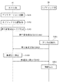
図5は、図1に示す触感呈示装置におけるホスト部10およびハプティック部20の他の動作例を示すシーケンス図である。
FIG. 5 is a sequence diagram showing another operation example of the
ホスト部10において、主制御部11が押下荷重に対応した処理を行うアプリケーションを起動すると、表示部42には、押しボタン等の押下荷重対応エリアを含むユーザインタフェースが表示される(ステップS101)。そして、主制御部11は、触感呈示制御部21に押下荷重検出指示を送信する(ステップS107)。
In the
ハプティック部20では、触感呈示制御部21は、主制御部11から押下荷重検出指示を受信すると、押下荷重の検出を開始する。触感呈示制御部21は、定期的に圧電素子22の出力電圧を取得して、タッチセンサ32にかかる押下荷重を検出する(ステップS201a〜S201c)。触感呈示制御部21が検出する押下荷重は、触感呈示の制御のために検出された情報である。しかし、本実施形態に係る触感呈示制御部21は、定期的に取得した押下荷重を、ホスト部10の主制御部11に通知する(ステップS202a〜S202c)。これにより、主制御部11は、押下荷重を考慮したアプリケーション処理を行うことができる。
In the
ホスト部10において、押下荷重に対応した処理を行うアプリケーションが終了すると(ステップS108)、主制御部11は、触感呈示制御部21に押下荷重停止指示を送信する(ステップS109)。 When the application that performs processing corresponding to the pressing load is completed in the host unit 10 (step S108), the main control unit 11 transmits a pressing load stop instruction to the tactile sensation presentation control unit 21 (step S109).
ハプティック部20では、触感呈示制御部21は、主制御部11から押下荷重停止指示を受信すると、押下荷重の検出を停止する(ステップS204)。
In the
このように、本実施形態によれば、主制御部11は、押下荷重に対応した処理を行うアプリケーション起動時に触感呈示制御部21に押下荷重検出指示を送信し、アプリケーション終了時に触感呈示制御部21に押下荷重停止指示を送信する。触感呈示制御部21は、主制御部11から押下荷重検出指示を受けると押下荷重の検出を開始し、主制御部11から押下荷重停止指示を受けると押下荷重の検出を停止する。これにより、ホスト部10とハプティック部20とのデュアルチップ間で、触感呈示のために検出された押下荷重に関する信号を交換することにより、押下荷重に基づくアプリケーション処理を行うことができる。すなわち、主制御部11は、押下荷重に応じてアプリケーションのユーザインタフェースを変更したり、押下荷重対応エリアに関連付けられた処理を実行したりすることが可能となる。特に、触感呈示制御部21は、主制御部11から押下荷重検出指示を受けてから押下荷重を検出するため、不要な押下荷重の検出を抑えることができ、触感呈示装置全体の処理負荷及び消費電力を低減させることができる。また、押下荷重に対応した処理を行うアプリケーションが終了した場合には、触感呈示制御部21は、押下荷重の検出を停止するため、触感呈示装置全体の処理負荷及び消費電力をさらに低減させることができる。なお、押下荷重の検出及び停止は、アプリケーションの起動及び終了により切り替えるだけでなく、スリープモードへの移行及び解除など、触感呈示装置の動作状態に応じて切り替えることも可能である。
As described above, according to the present embodiment, the main control unit 11 transmits a pressing load detection instruction to the tactile sensation
本発明は、上記実施の形態にのみ限定されるものではなく、幾多の変形または変更が可能である。例えば、主制御部11が、ハプティック部20の記憶部23に格納されていない触感呈示用のパラメータテーブルによりハプティック部20を制御したい状況も考えられる。この場合、主制御部11は、例えば、触感呈示指示(S105)に当該触感呈示用のパラメータテーブル自体を含め、触感呈示制御部21に送信することもできる。当該パラメータテーブルを受信した触感呈示制御部21は、受信したパラメータテーブルに応じて圧電素子22を駆動するとともに、受信したパラメータテーブルを記憶部23に格納することもできる。
The present invention is not limited to the above-described embodiment, and many variations or modifications are possible. For example, there may be a situation where the main control unit 11 wants to control the
また、上記実施の形態では、圧電素子22により触感呈示部および荷重検出部を構成したが、触感呈示部および荷重検出部は、分離して設けてもよい。この場合、触感呈示部は、圧電素子に限らず、偏心モータやソレノイド等の他の公知の振動手段を用いることが可能である。また、タッチセンサを積層型の圧電素子を介して支持することも可能である。同様に、荷重検出部についても、圧電素子に限らず、歪センサ等の他の公知の荷重検出手段を用いることが可能である。さらに、荷重検出部は、省略することも可能である。また、本発明は、表示部を備えず、タッチセンサ上に押下荷重対応エリアが印刷等により直接描画されている場合も、適用することができる。
Moreover, in the said embodiment, although the tactile sense presentation part and the load detection part were comprised by the
また、本発明に係る入力装置は、圧電素子の出力に基づいて検出される押圧荷重が触感を呈示する基準を満たした際に、当該圧電素子を駆動する。ここで、圧電素子の出力に基づいて検出される押圧荷重が触感を呈示する基準を満たした際とは、検出される押圧荷重が触感を呈示する基準値に達した際であってもよいし、検出される押圧荷重が触感を呈示する基準値を超えた際でもよいし、圧電素子の出力に基づいて触感を呈示する基準値が検出された際でもよい。 Further, the input device according to the present invention drives the piezoelectric element when the pressing load detected based on the output of the piezoelectric element satisfies a criterion for presenting tactile sensation. Here, the case where the pressing load detected based on the output of the piezoelectric element satisfies the standard for presenting tactile sensation may be the time when the detected pressing load reaches a reference value for presenting tactile sensation. The detected pressing load may exceed a reference value that provides tactile sensation, or may be detected when a reference value that provides tactile sensation is detected based on the output of the piezoelectric element.
10 ホスト部
11 主制御部
12 主記憶部
20 ハプティック部
21 触感呈示制御部
22 圧電素子
23 記憶部
31 タッチセンサ制御部
32 タッチセンサ
41 表示制御部
42 表示部
50 支持部材
DESCRIPTION OF
Claims (2)
触感呈示のために該タッチセンサに対する押下荷重を検出する荷重検出部と、
前記タッチセンサのタッチ面を振動させる触感呈示部と、
該触感呈示部の駆動を制御する触感呈示制御部と、
押下荷重に対応した処理を行うアプリケーションを制御する主制御部と、を備え、
前記主制御部は、前記アプリケーション起動時に前記触感呈示制御部に押下荷重検出指示を送信し、アプリケーション終了時に前記触感呈示制御部に押下荷重停止指示を送信し、
前記触感呈示制御部は、前記主制御部から前記押下荷重検出指示を受けると、前記押下荷重の検出を開始し、前記主制御部から前記押下荷重停止指示を受けると、前記押下荷重の検出を停止する、ことを特徴とする触感呈示装置。 A touch sensor;
A load detection unit for detecting a pressing load on the touch sensor for tactile sensation presentation;
A tactile sensation providing unit that vibrates the touch surface of the touch sensor;
A tactile sensation presentation control unit that controls driving of the tactile sensation presentation unit;
A main control unit that controls an application that performs processing corresponding to the pressing load,
The main control unit transmits a pressing load detection instruction to the tactile sensation presentation control unit at the time of starting the application, and transmits a pressing load stop instruction to the tactile sensation presentation control unit at the end of the application,
The tactile sensation presentation control unit starts detection of the pressing load when receiving the pressing load detection instruction from the main control unit, and detects the pressing load when receiving the pressing load stop instruction from the main control unit. A tactile sensation presentation apparatus characterized by stopping.
触感呈示のために該タッチセンサに対する押下荷重を検出する荷重検出部と、
前記タッチセンサのタッチ面を振動させる触感呈示部と、
該触感呈示部の駆動を制御する触感呈示制御部と、
押下荷重に対応した処理を行うアプリケーションを制御する主制御部と、を備える触感呈示装置の制御方法であって、
前記主制御部が、前記アプリケーション起動時に前記触感呈示制御部に押下荷重検出指示を送信し、アプリケーション終了時に前記触感呈示制御部に押下荷重停止指示を送信するステップと、
前記触感呈示制御部が、前記主制御部から前記押下荷重検出指示を受けると、前記押下荷重の検出を開始し、前記主制御部から前記押下荷重停止指示を受けると、前記押下荷重の検出を停止するステップと、を有することを特徴とする触感呈示装置の制御方法。 A touch sensor;
A load detection unit for detecting a pressing load on the touch sensor for tactile sensation presentation;
A tactile sensation providing unit that vibrates the touch surface of the touch sensor;
A tactile sensation presentation control unit that controls driving of the tactile sensation presentation unit;
A control method for a tactile sensation providing apparatus comprising: a main control unit that controls an application that performs processing corresponding to a pressing load;
The main control unit transmits a pressing load detection instruction to the tactile sensation presentation control unit at the time of starting the application, and transmits a pressing load stop instruction to the tactile sensation presentation control unit at the end of the application;
When the tactile sensation presentation control unit receives the pressing load detection instruction from the main control unit, the tactile sensation presentation control unit starts detecting the pressing load, and receives the pressing load stop instruction from the main control unit, detects the pressing load. A tactile sensation providing apparatus control method comprising: a step of stopping.
Priority Applications (6)
| Application Number | Priority Date | Filing Date | Title |
|---|---|---|---|
| JP2010168582A JP5841714B2 (en) | 2010-07-27 | 2010-07-27 | Tactile sensation presentation apparatus and control method for tactile sensation presentation apparatus |
| PCT/JP2011/003843 WO2012014387A1 (en) | 2010-07-27 | 2011-07-05 | Tactile feedback device, and tactile feedback device control method |
| CN201180037011.1A CN103124950B (en) | 2010-07-27 | 2011-07-05 | Force-feedback device and the method for Force-feedback device |
| EP11811992.4A EP2600226B1 (en) | 2010-07-27 | 2011-07-05 | Tactile feedback device, and tactile feedback device control method |
| US13/812,420 US9317117B2 (en) | 2010-07-27 | 2011-07-05 | Tactile sensation providing apparatus and control method for tactile sensation providing apparatus |
| KR1020137003627A KR20130069725A (en) | 2010-07-27 | 2011-07-05 | Tactile sensation providing apparatus and control method for tactile sensation providing apparatus |
Applications Claiming Priority (1)
| Application Number | Priority Date | Filing Date | Title |
|---|---|---|---|
| JP2010168582A JP5841714B2 (en) | 2010-07-27 | 2010-07-27 | Tactile sensation presentation apparatus and control method for tactile sensation presentation apparatus |
Publications (2)
| Publication Number | Publication Date |
|---|---|
| JP2012027860A JP2012027860A (en) | 2012-02-09 |
| JP5841714B2 true JP5841714B2 (en) | 2016-01-13 |
Family
ID=45529624
Family Applications (1)
| Application Number | Title | Priority Date | Filing Date |
|---|---|---|---|
| JP2010168582A Active JP5841714B2 (en) | 2010-07-27 | 2010-07-27 | Tactile sensation presentation apparatus and control method for tactile sensation presentation apparatus |
Country Status (6)
| Country | Link |
|---|---|
| US (1) | US9317117B2 (en) |
| EP (1) | EP2600226B1 (en) |
| JP (1) | JP5841714B2 (en) |
| KR (1) | KR20130069725A (en) |
| CN (1) | CN103124950B (en) |
| WO (1) | WO2012014387A1 (en) |
Cited By (1)
| Publication number | Priority date | Publication date | Assignee | Title |
|---|---|---|---|---|
| JP7467787B2 (en) | 2018-03-30 | 2024-04-16 | トーヨーカネツ株式会社 | Transport System |
Families Citing this family (7)
| Publication number | Priority date | Publication date | Assignee | Title |
|---|---|---|---|---|
| JP5905312B2 (en) * | 2012-03-27 | 2016-04-20 | 京セラ株式会社 | Sound equipment |
| JP6062573B2 (en) * | 2014-01-30 | 2017-01-18 | 京セラドキュメントソリューションズ株式会社 | Touch panel device and touch panel control method |
| CN103995591B (en) | 2014-05-16 | 2017-03-01 | 北京智谷睿拓技术服务有限公司 | The method and apparatus producing tactile feedback |
| JP2017111462A (en) * | 2015-11-27 | 2017-06-22 | 京セラ株式会社 | Feeling presentation device and feeling presentation method |
| US9880627B2 (en) | 2015-12-15 | 2018-01-30 | Immersion Corporation | Automated haptic setting generation |
| CN112805096B (en) | 2019-04-19 | 2022-04-12 | 株式会社村田制作所 | Vibration device |
| CN113054978B (en) * | 2021-03-16 | 2022-11-25 | 科世达(上海)机电有限公司 | Automobile touch device and touch vibration device thereof |
Family Cites Families (13)
| Publication number | Priority date | Publication date | Assignee | Title |
|---|---|---|---|---|
| US5734373A (en) * | 1993-07-16 | 1998-03-31 | Immersion Human Interface Corporation | Method and apparatus for controlling force feedback interface systems utilizing a host computer |
| JPH10293644A (en) | 1997-04-18 | 1998-11-04 | Idec Izumi Corp | Display device having touch panel |
| JP2006048302A (en) * | 2004-08-03 | 2006-02-16 | Sony Corp | Piezoelectric complex unit, its manufacturing method, its handling method, its control method, input/output device and electronic equipment |
| JP2006106819A (en) * | 2004-09-30 | 2006-04-20 | Toshiba Corp | Information processor |
| JP2007323410A (en) * | 2006-06-01 | 2007-12-13 | Buffalo Inc | External extension device |
| JP4968515B2 (en) * | 2006-11-15 | 2012-07-04 | ソニー株式会社 | Substrate support vibration structure, input device with tactile function, and electronic device |
| GB2446167B (en) | 2007-02-02 | 2011-08-17 | Satmap Systems Ltd | Mapping system |
| JP2008225690A (en) * | 2007-03-09 | 2008-09-25 | Sony Corp | Vibration body, tactile sense function-equipped input device, and electronic equipment |
| JP4871251B2 (en) | 2007-12-14 | 2012-02-08 | 株式会社エヌ・ティ・ティ・ドコモ | Information processing device |
| JP4767996B2 (en) * | 2008-05-14 | 2011-09-07 | 東芝テック株式会社 | Coordinate input device program, coordinate calculation program, and information processing device |
| JP4736066B2 (en) * | 2008-09-29 | 2011-07-27 | 株式会社デンソー | Operation input device |
| KR101737829B1 (en) | 2008-11-10 | 2017-05-22 | 삼성전자주식회사 | Motion Input Device For Portable Device And Operation Method using the same |
| JP4746086B2 (en) | 2008-12-25 | 2011-08-10 | 京セラ株式会社 | Input device |
-
2010
- 2010-07-27 JP JP2010168582A patent/JP5841714B2/en active Active
-
2011
- 2011-07-05 CN CN201180037011.1A patent/CN103124950B/en active Active
- 2011-07-05 WO PCT/JP2011/003843 patent/WO2012014387A1/en active Application Filing
- 2011-07-05 KR KR1020137003627A patent/KR20130069725A/en not_active Application Discontinuation
- 2011-07-05 US US13/812,420 patent/US9317117B2/en active Active
- 2011-07-05 EP EP11811992.4A patent/EP2600226B1/en active Active
Cited By (1)
| Publication number | Priority date | Publication date | Assignee | Title |
|---|---|---|---|---|
| JP7467787B2 (en) | 2018-03-30 | 2024-04-16 | トーヨーカネツ株式会社 | Transport System |
Also Published As
| Publication number | Publication date |
|---|---|
| WO2012014387A1 (en) | 2012-02-02 |
| EP2600226A4 (en) | 2017-03-22 |
| CN103124950A (en) | 2013-05-29 |
| JP2012027860A (en) | 2012-02-09 |
| EP2600226A1 (en) | 2013-06-05 |
| KR20130069725A (en) | 2013-06-26 |
| EP2600226B1 (en) | 2019-04-03 |
| US9317117B2 (en) | 2016-04-19 |
| US20130201138A1 (en) | 2013-08-08 |
| CN103124950B (en) | 2016-06-08 |
Similar Documents
| Publication | Publication Date | Title |
|---|---|---|
| JP5841713B2 (en) | Tactile sensation presentation apparatus and control method for tactile sensation presentation apparatus | |
| JP5841714B2 (en) | Tactile sensation presentation apparatus and control method for tactile sensation presentation apparatus | |
| WO2012014385A1 (en) | Tactile feedback device, and tactile feedback device control method | |
| JP5889519B2 (en) | Tactile sensation presentation apparatus and control method of tactile sensation presentation apparatus | |
| JP5437786B2 (en) | Tactile presentation device | |
| JP5529981B2 (en) | Electronics | |
| US9804674B2 (en) | Tactile sensation providing apparatus | |
| JP5912235B2 (en) | Tactile sensation presentation apparatus and control method for tactile sensation presentation apparatus |
Legal Events
| Date | Code | Title | Description |
|---|---|---|---|
| A621 | Written request for application examination |
Free format text: JAPANESE INTERMEDIATE CODE: A621 Effective date: 20130614 |
|
| A131 | Notification of reasons for refusal |
Free format text: JAPANESE INTERMEDIATE CODE: A131 Effective date: 20140401 |
|
| A02 | Decision of refusal |
Free format text: JAPANESE INTERMEDIATE CODE: A02 Effective date: 20141028 |
|
| A61 | First payment of annual fees (during grant procedure) |
Free format text: JAPANESE INTERMEDIATE CODE: A61 Effective date: 20151116 |
|
| R150 | Certificate of patent (=grant) or registration of utility model |
Ref document number: 5841714 Country of ref document: JP Free format text: JAPANESE INTERMEDIATE CODE: R150 |