JP5836628B2 - Control system evaluation apparatus, evaluation method, and program - Google Patents
Control system evaluation apparatus, evaluation method, and program Download PDFInfo
- Publication number
- JP5836628B2 JP5836628B2 JP2011093511A JP2011093511A JP5836628B2 JP 5836628 B2 JP5836628 B2 JP 5836628B2 JP 2011093511 A JP2011093511 A JP 2011093511A JP 2011093511 A JP2011093511 A JP 2011093511A JP 5836628 B2 JP5836628 B2 JP 5836628B2
- Authority
- JP
- Japan
- Prior art keywords
- characteristic
- control system
- fluctuation range
- evaluation
- frequency
- Prior art date
- Legal status (The legal status is an assumption and is not a legal conclusion. Google has not performed a legal analysis and makes no representation as to the accuracy of the status listed.)
- Active
Links
Images


Classifications
-
- G—PHYSICS
- G05—CONTROLLING; REGULATING
- G05B—CONTROL OR REGULATING SYSTEMS IN GENERAL; FUNCTIONAL ELEMENTS OF SUCH SYSTEMS; MONITORING OR TESTING ARRANGEMENTS FOR SUCH SYSTEMS OR ELEMENTS
- G05B13/00—Adaptive control systems, i.e. systems automatically adjusting themselves to have a performance which is optimum according to some preassigned criterion
- G05B13/02—Adaptive control systems, i.e. systems automatically adjusting themselves to have a performance which is optimum according to some preassigned criterion electric
Landscapes
- Engineering & Computer Science (AREA)
- Health & Medical Sciences (AREA)
- Artificial Intelligence (AREA)
- Computer Vision & Pattern Recognition (AREA)
- Evolutionary Computation (AREA)
- Medical Informatics (AREA)
- Software Systems (AREA)
- Physics & Mathematics (AREA)
- General Physics & Mathematics (AREA)
- Automation & Control Theory (AREA)
- Feedback Control In General (AREA)
Description
本発明は、制御系の評価を支援する評価装置、および、その評価処理に関する。 The present invention relates to an evaluation apparatus that supports evaluation of a control system, and an evaluation process thereof.
操作量から制御量までの周波数特性が変動する制御対象に対し、制御量を望ましい目標値の範囲に収める制御器の設計方法として、H∞制御理論やμシンセシス理論などのロバスト制御理論が知られている。 Robust control theories such as H∞ control theory and μ-synthesis theory are known as controller design methods for controlling the controlled variable within the desired target range for controlled objects whose frequency characteristics vary from manipulated variable to controlled variable. ing.
しかし、上記の理論を用いても、ロバスト性や制御精度などの要求仕様や制御対象の特性によっては、すべての仕様を満たす制御器が存在しないことがある。その場合、要求仕様の制約を緩めて実現可能な制御器を求めることが多い。しかし、こうして得られる制御器は、制御対象の変動内でロバスト性を完全に有することを保証するものではなく、制御対象の変動に対して目標の制御精度を保証することができない場合がある。 However, even if the above theory is used, a controller that satisfies all specifications may not exist depending on required specifications such as robustness and control accuracy and characteristics of the control target. In that case, a controller that can be realized by loosening the restriction of the required specification is often sought. However, the controller thus obtained does not guarantee complete robustness within the variation of the controlled object, and may not guarantee the target control accuracy against the variation of the controlled object.
制御対象の変動の範囲において、設計した制御器によるロバスト制御系を漏れなく評価し、制御系において安定性や所望の制御精度が得られるか否かを確認し、制御器の設計変更の必要性を簡単に判断するための、制御系の評価支援装置が望まれる。 Evaluate the robust control system with the designed controller without omission within the range of control target fluctuations, confirm whether the control system can achieve stability and desired control accuracy, and need to change the controller design Therefore, an evaluation support apparatus for a control system for easily determining the above is desired.
具体例として、画像形成装置の感光体を駆動する制御系を説明する。中間転写体を有する画像形成装置の場合、感光体と中間転写体の接触部において、現像剤が感光体表面から中間転写体表面に移動する。 As a specific example, a control system for driving the photoreceptor of the image forming apparatus will be described. In the case of an image forming apparatus having an intermediate transfer member, the developer moves from the surface of the photosensitive member to the surface of the intermediate transfer member at the contact portion between the photosensitive member and the intermediate transfer member.
画像品質の観点から、感光体や中間転写体を所定の回転速度で精度よく回転させるために、感光体や中間転写体の駆動モータをフィードバック制御する場合がある。例えば、感光体のDCモータ駆動制御系における操作量は、モータ駆動の指令値であり、モータへ供給するパルス幅変調(PWM)信号のデューティ値である。また、同制御系の制御量は、感光体の回転速度である。つまり、制御器は、センサで検出した感光体の回転速度と目標回転速度の差から、PID制御やH∞制御などにより操作量を演算する。 From the viewpoint of image quality, there is a case where the drive motor of the photosensitive member or the intermediate transfer member is feedback controlled in order to rotate the photosensitive member or the intermediate transfer member with a predetermined rotational speed with high accuracy. For example, the operation amount of the photoreceptor in the DC motor drive control system is a motor drive command value, which is a duty value of a pulse width modulation (PWM) signal supplied to the motor. The control amount of the control system is the rotational speed of the photoconductor. That is, the controller calculates the operation amount by PID control, H∞ control, or the like from the difference between the rotational speed of the photosensitive member detected by the sensor and the target rotational speed.
感光体と中間転写体は、現像剤の量や使用環境などにより、その接触部において滑ったり滑らなかったりする。つまり、接触部における滑りに応じて、感光体駆動系の操作量から制御量までの伝達特性が大きく変化する。滑らない場合は、感光体の速度を制御しても、中間転写体の影響により操作量に対する制御量の反応が鈍い。また、滑る場合は、感光体の速度は中間転写体の速度に影響されず、操作量に対する制御量の反応は敏感である。 The photosensitive member and the intermediate transfer member may or may not slide at the contact portion depending on the amount of developer and the usage environment. That is, the transfer characteristics from the operation amount to the control amount of the photosensitive member drive system greatly change according to the slip at the contact portion. If it does not slip, even if the speed of the photosensitive member is controlled, the response of the control amount to the operation amount is slow due to the influence of the intermediate transfer member. In the case of sliding, the speed of the photosensitive member is not affected by the speed of the intermediate transfer member, and the response of the control amount to the operation amount is sensitive.
さらに、実際の使用環境において、接触部にどの程度の滑りがあるかは不明である。そのため、滑らない状態から完全に滑る状態(以下、接触部の状態)まで、どの状態においても感光体が安定に回転し、精度よく所定速度が得られる制御系の構築が必要になる。このようなロバスト性を必要とする制御系の設計に、H∞制御理論やμシンセシス理論を適用することが考えられる。しかし、接触部の状態に対するロバスト性や速度精度などの要求仕様や、駆動系の共振周波数などの特性により、すべての仕様を満たす制御器が存在しない可能性がある。 Furthermore, it is unclear how much slippage there is in the contact area in the actual use environment. Therefore, it is necessary to construct a control system that can stably rotate the photoconductor in any state from a non-slip state to a completely slip state (hereinafter referred to as a contact portion state) and obtain a predetermined speed with high accuracy. It is conceivable to apply H∞ control theory or μ synthesis theory to the design of control systems that require such robustness. However, there may be no controller that satisfies all specifications depending on required specifications such as robustness and speed accuracy with respect to the state of the contact portion, and characteristics such as the resonance frequency of the drive system.
例えば、ロバスト性を犠牲にして、速度精度の仕様を満たす制御器を採用する場合は、設計仕様から外れる接触部の状態において、感光体の回転がどのような挙動を示すかを評価する必要がある。逆に、速度精度を犠牲にして、ロバスト性を満たす制御器を採用する場合は、速度精度がどの程度満たされないかを評価する必要がある。 For example, when adopting a controller that satisfies the specifications for speed accuracy at the expense of robustness, it is necessary to evaluate how the rotation of the photoconductor behaves in the state of the contact portion that deviates from the design specifications. is there. Conversely, when a controller that satisfies the robustness is employed at the expense of speed accuracy, it is necessary to evaluate how much the speed accuracy is not satisfied.
これら評価においては、接触部の状態により変動する伝達特性を漏れなく評価しなければならない。もし、使用環境において感光体駆動系の特性が評価漏れの特性と一致した場合、制御系が発散し、感光体の回転停止、目標速度を超える高速回転、大きな速度変動などが生じる可能性がある。 In these evaluations, transmission characteristics that vary depending on the state of the contact portion must be evaluated without omission. If the characteristics of the photoconductor drive system match the characteristics of the evaluation failure in the usage environment, the control system may diverge, causing the photoconductor to stop rotating, high-speed rotation exceeding the target speed, and large speed fluctuations. .
ロバスト制御系の安定性や制御精度の評価装置として、制御対象を時変系伝達関数で定式化して時系列の制御シミュレーションを行い、変動する制御対象における制御系の挙動を検証するシミュレーション装置が知られている(例えば、特許文献1)。この装置によれば、時変系で定式化できる制御対象の特性の変動内において、ロバスト制御系の挙動を漏れなく確認することができる。 As a device for evaluating the stability and control accuracy of a robust control system, a simulation device that formulates a controlled object with a time-varying transfer function and performs a time-series control simulation and verifies the behavior of the controlled system in a varying controlled object is known. (For example, Patent Document 1). According to this apparatus, the behavior of the robust control system can be confirmed without omission within the fluctuation of the characteristics of the controlled object that can be formulated in a time-varying system.
しかし、上記技術の適用は、制御対象の特性の変動が時変系伝達関数に定式化できる場合に限られる。複雑な時系列変動や、時系列に変動しない制御対象の個体差や環境による特性の変動に対して、すべての条件を定式化するのは困難である。画像形成装置の接触部の状態による伝達特性の変動も特性の変動の一例であり、操作量から制御量までの周波数特性に不確かさをもつ制御対象における定式化には膨大な時間を要する。 However, the application of the above technique is limited to the case where the variation of the characteristics of the controlled object can be formulated into a time-varying transfer function. It is difficult to formulate all conditions for complex time-series fluctuations, individual differences of controlled objects that do not vary in time series, and fluctuations in characteristics due to the environment. Variations in the transfer characteristics due to the state of the contact portion of the image forming apparatus are an example of the fluctuations in the characteristics, and formulation of a control target having uncertainty in the frequency characteristics from the manipulated variable to the controlled variable requires an enormous amount of time.
そこで、特性変動の定式化が困難な制御対象に対する制御系の評価装置として、市販ソフトウェアであるMATLAB(登録商標)が知られている。このソフトウェアは、制御対象の特性の変動範囲内から特性をランダムに抽出してモンテカルロ解析を行い、制御系のナイキスト線図など、制御系評価線図を出力する。ユーザは、出力結果を参照して、ロバスト制御系の安定性や制御精度を確認し、制御器の設計変更の必要性を判断することができる。 Therefore, MATLAB (registered trademark), which is commercially available software, is known as a control system evaluation apparatus for a control target for which it is difficult to formulate characteristic variation. This software randomly extracts characteristics from the fluctuation range of the characteristics of the controlled object, performs Monte Carlo analysis, and outputs a control system evaluation diagram such as a Nyquist diagram of the control system. The user can confirm the stability and control accuracy of the robust control system by referring to the output result, and can determine the necessity of the controller design change.
しかし、モンテカルロ解析によってロバスト制御系の安定性や制御精度を評価すれば、制御対象の特性の変動範囲内から特性をランダムに抽出するため、制御系の評価に漏れが生じる場合がある。 However, if the stability and control accuracy of the robust control system are evaluated by Monte Carlo analysis, characteristics may be randomly extracted from within the fluctuation range of the characteristics of the controlled object, which may cause a leak in the evaluation of the control system.
本発明は、周波数特性に不確かさを有する制御対象を含む制御系の安定性を正確に評価することを目的とする。 An object of the present invention is to accurately evaluate the stability of a control system including a control target having uncertainty in frequency characteristics.
本発明は、前記の目的を達成する一手段として、以下の構成を備える。 The present invention has the following configuration as one means for achieving the above object.
制御器の周波数特性を取得し、制御対象のゲイン特性および位相差特性を取得し、複素座標系において、前記ゲイン特性の変動範囲と前記位相差特性の変動範囲が重なる領域を前記制御対象の周波数特性の変動範囲として、前記周波数特性の変動範囲と前記制御器の周波数特性から前記制御系の一巡伝達特性とその変動範囲を演算し、前記一巡伝達特性とその変動範囲から前記制御系の安定性を評価することを特徴とする。 Obtain the frequency characteristics of the controller, obtain the gain characteristics and phase difference characteristics of the controlled object, and, in a complex coordinate system, define the area where the fluctuation range of the gain characteristics and the fluctuation range of the phase difference characteristics overlap As a fluctuation range of the characteristic, a round trip transmission characteristic of the control system and its fluctuation range are calculated from the fluctuation range of the frequency characteristic and the frequency characteristic of the controller, and the stability of the control system is calculated from the round trip transmission characteristic and the fluctuation range. It is characterized by evaluating.
本発明によれば、周波数特性に不確かさを有する制御対象を含む制御系の安定性を正確に評価することができる。 According to the present invention, it is possible to accurately evaluate the stability of a control system including a control object having uncertainty in frequency characteristics.
以下、本発明にかかる実施例の制御系の評価処理を図面を参照して詳細に説明する。なお、以下では、画像形成装置の感光体駆動制御に本発明を適用する例を説明する。 Hereinafter, a control system evaluation process according to an embodiment of the present invention will be described in detail with reference to the drawings. In the following, an example in which the present invention is applied to photoconductor drive control of an image forming apparatus will be described.
[装置の構成]
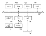
図1のブロック図により実施例の評価装置の構成例を説明する。
[Device configuration]
A configuration example of the evaluation apparatus of the embodiment will be described with reference to the block diagram of FIG.
CPU101は、RAM102をワークメモリとして、ROM103やハードディスクドライブ(HDD)108などの不揮発性メモリに格納されたOSを含む各種プログラムを実行し、システムバス107を介して、後述する構成を制御する。HDD108が格納する各種プログラムには、後述する制御系の評価処理のプログラムが含まれる。
The
汎用インタフェイス(I/F)104は、例えばUSBのようなシリアルバスインタフェイスで、マウスやキーボード、メモリカードリーダライタ、リムーバブルディスクドライブなどの入力デバイス111が接続される。ビデオカード(VC)105は、ビデオインタフェイスで、LCDなどのモニタ113が接続される。ネットワークインタフェイスカード(NIC)106は、LANなどのネットワーク114に接続されるネットワークインタフェイスである。CPU101は、NIC106を介してネットワーク上のサーバ装置などとデータのやり取りが可能である。
The general-purpose interface (I / F) 104 is a serial bus interface such as USB, to which an
CPU101は、モニタ113にユーザインタフェイス(UI)を表示する。ユーザは、マウスやキーボードを操作して、UIに対して指示やデータや入力する。CPU101は、ユーザ指示やデータを入力し、それら入力に従いプログラムを実行して各種処理を行う。
The
なお、図1に示す評価装置は、汎用のコンピュータ装置に制御系の評価処理のプログラムを供給することにより実現可能である。 The evaluation apparatus shown in FIG. 1 can be realized by supplying a control system evaluation processing program to a general-purpose computer apparatus.
[機能構成]
図2のブロック図により実施例の評価装置の機能構成例を説明する。つまり、図2に示す評価部31は、CPU101が制御系の評価処理を行う場合の機能構成例を示す。
[Function configuration]
A functional configuration example of the evaluation apparatus of the embodiment will be described with reference to the block diagram of FIG. That is, the
評価部31は、モニタ113にUIを表示し、入力デバイス111を介してユーザの指示を入力し、ユーザが指示するデータを入力デバイス111を介して取得したり、HDD108やサーバ装置から取得し、制御系の評価処理を行う。そして、評価結果としてグラフや様々な情報をUIに表示する。ユーザは、UIの表示を参照して、ロバスト制御系の安定性や制御精度を確認し、制御器の設計変更の必要性を判断する。
The
特性データ取得部11は、制御器の周波数特性を示すデータを取得する第一の取得部である。変動データ取得部12は、制御対象のゲイン特性および位相差特性を示すデータを取得する第二の取得部である。なお、これらデータは、入力デバイス111、HDD108、サーバ装置などから取得される。
The characteristic
伝達特性演算部13は、制御対象のゲイン特性および位相差特性を示すデータが表すゲインの変動範囲と位相差の変動範囲が複素座標系において重なる領域を、制御対象の周波数特性の変動範囲とする。そして、制御対象の周波数特性の変動範囲と制御器の周波数特性から、制御系の一巡伝達特性と、その変動範囲を演算する。
The transfer
評価特性演算部14は、座標変換部21および感度特性演算部22を有する。座標変換部21は、一巡伝達特性の変動範囲を複素座標系に座標変換する。感度特性演算部22は、複素座標系において点(-1+j0)から一巡伝達特性の変動範囲までの距離を演算し、速度を変動させる外乱から制御量までの外乱感度特性の変動領域を求める。
The evaluation
安定性判定部15は、一巡伝達特性に対して、ナイキストの安定判別法の考え方を用いて、制御系の安定性を判定し、安定性の判定結果を示すデータを出力する。出力部16は、一巡伝達特性の変動範囲、外乱感度特性の変動領域、および、安定性の判定結果をそれぞれ示すデータを入力して、それらをモニタ113のUIに表示する。なお、出力部16は、それらデータを記憶メディア、HDD108、サーバ装置などに格納することもできる。
The
[制御系の評価処理]
図3のフローチャートにより制御系の評価処理を説明する。
[Control system evaluation process]
The control system evaluation process will be described with reference to the flowchart of FIG.
特性データ取得部11は、制御器の周波数特性を示すデータを取得する(S101)。制御器の周波数特性は、センサで検出した感光体の速度と目標速度の差から、モータへ供給するパルス幅変調(PWM)信号のデューティ値までの伝達特性を示す。図4により周波数特性を示すデータの一例を示す。つまり、周波数特性は、周波数に対するゲインと位相差を表す。また、制御器の周波数特性は、伝達関数式として与えられてもよい。その場合、伝達関数式から周波数に対するゲインと位相差を演算することができる。
The characteristic
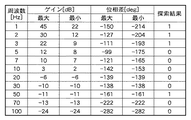
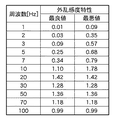
次に、変動データ取得部12は、制御対象のゲイン特性および位相差特性を示すデータを取得する(S102)。制御対象のゲイン特性および位相差特性は、モータへ供給するPWM信号のデューティ値から、感光体の速度までの伝達特性を示す。図5によりゲイン特性および位相差特性の一例を示す。つまり、ゲイン特性および位相差特性は、周波数に対するゲインの変動範囲および位相差の変動範囲を表す。
Next, the fluctuation
図5には、ゲインの最大値と最小値、位相差の最大値と最小値を変動範囲として表す例を示す。つまり、感光体と中間転写体の接触部の状態により、各周波数において、ゲインが最大値から最小値の範囲で変動し、位相差も最大値から最小値の範囲で変動する。ここで「位相差が大きい」とは正の方向に大きいものと定義する。 FIG. 5 shows an example in which the maximum value and the minimum value of the gain and the maximum value and the minimum value of the phase difference are expressed as the fluctuation range. That is, the gain varies in the range from the maximum value to the minimum value, and the phase difference also varies in the range from the maximum value to the minimum value, depending on the state of the contact portion between the photosensitive member and the intermediate transfer member. Here, “large phase difference” is defined as being large in the positive direction.
また、変動範囲は中心値と変動幅で与えられてもよい。その場合、中心値±変動幅を演算することで、最大値と最小値が得られる。また、特性の変動を表す二つの伝達関数式として与えられる場合は、伝達関数式から周波数に対する最大値と最小値を演算することができる。 Further, the fluctuation range may be given by a center value and a fluctuation range. In that case, the maximum value and the minimum value can be obtained by calculating the center value ± the fluctuation range. Further, when given as two transfer function expressions representing the fluctuation of characteristics, the maximum value and the minimum value with respect to the frequency can be calculated from the transfer function expression.
次に、伝達特性演算部13は、制御系の一巡伝達特性と、その変動範囲を演算する(S103)。まず、図6により制御対象の周波数特性の変動範囲の求め方を説明する。
Next, the transfer
図6は、図5に示すデータの7Hzにおける制御対象のゲインの変動範囲および位相差の変動範囲を複素座標系に変換した状態を表す。複素座標系において、ゲインは原点からの距離で表され、位相差は正の方向の実数(Re)軸を0度として反時計回りを正の方向とする角度で表される。7Hzにおけるゲインの変動範囲は、ゲインの最大値36dBに対応する円と、最小値33dBに対応する円に挟まれる領域501として表される。また、7Hzにおける位相差の変動範囲は、位相差の最大値-45度に対応する半直線と、最小値-89度に対応する半直線に挟まれる領域502として表される。伝達特性演算部13は、領域501と502が重なる領域503を制御対象の周波数特性の変動範囲とする。
FIG. 6 shows a state where the fluctuation range of the gain to be controlled and the fluctuation range of the phase difference at 7 Hz in the data shown in FIG. 5 are converted into the complex coordinate system. In the complex coordinate system, the gain is represented by a distance from the origin, and the phase difference is represented by an angle in which the real number (Re) axis in the positive direction is 0 degrees and the counterclockwise direction is the positive direction. The gain fluctuation range at 7 Hz is represented as a
次に、制御対象の周波数特性の変動範囲と制御器の周波数特性から、一巡伝達特性と、その変動範囲を演算する処理を説明する。 Next, a round transfer characteristic and a process for calculating the fluctuation range from the fluctuation range of the frequency characteristic to be controlled and the frequency characteristic of the controller will be described.
ゲインがデシベルで表される場合、所定周波数における一巡伝達特性のゲインは、当該周波数の制御器のゲインと、当該周波数の制御対象のゲインの和として演算される。また、所定周波数における一巡伝達特性の位相差は、当該周波数の制御器の位相差と、当該周波数の制御対象の位相差の和として演算される。つまり、制御対象の周波数特性が変動する場合、制御対象のゲインの変動範囲と制御器のゲインの和から、一巡伝達特性のゲインの変動範囲を得ることができる。また、制御対象の位相差の変動範囲と制御器の位相差の和から、一巡伝達特性の位相差の変動範囲を得ることができる。 When the gain is expressed in decibels, the gain of the loop transfer characteristic at the predetermined frequency is calculated as the sum of the gain of the controller of the frequency and the gain of the control target of the frequency. Further, the phase difference of the round transfer characteristic at a predetermined frequency is calculated as the sum of the phase difference of the controller of the frequency and the phase difference of the control target of the frequency. That is, when the frequency characteristic of the control target varies, the gain fluctuation range of the loop transfer characteristic can be obtained from the sum of the gain variation range of the control target and the gain of the controller. In addition, the fluctuation range of the phase difference of the round transfer characteristic can be obtained from the sum of the fluctuation range of the phase difference to be controlled and the phase difference of the controller.
図7により一巡伝達特性の一例を示す。制御対象のゲインの変動範囲と位相差の変動範囲が複素座標系において重なる領域を、制御対象の周波数特性の変動範囲とすることにより、漏れのない一巡伝達特性を得ることができ、ロバスト制御系を漏れなく評価することができる。 FIG. 7 shows an example of a round transfer characteristic. By setting the region where the fluctuation range of the gain to be controlled and the fluctuation range of the phase difference overlap in the complex coordinate system as the fluctuation range of the frequency characteristic of the control target, it is possible to obtain a leak-free round transfer characteristic, and a robust control system Can be evaluated without omission.
次に、座標変換部21は、一巡伝達特性の変動範囲を複素座標系に座標変換する(S104)。安定性判定部15は、制御系の一巡伝達特性と、その変動範囲に基づき、位相差が-180度になる周波数を探索し(S105)、探索結果に基づき制御系の安定性を判定する(S106)。
Next, the coordinate
安定性判定部15は、一巡伝達特性と、その変動範囲を示すデータから、位相差の変動範囲に-180度を含むデータ、並びに、隣接するデータ(周波数)との間で位相差が-180度になるデータを探索する。図7に示すデータにおいて、この探索によって検出されるデータは探索結果フィールドの値が‘1’のデータである。周波数1Hz、2Hz、3Hzのデータは位相差の変動範囲に-180度を含み、周波数50Hzのデータは隣接する70Hzのデータとの間で位相差が-180度になる。
The
続いて、安定性判定部15は、次の二つの条件を満たすデータが存在するか否かを判定する。二つの条件のうち、何れかが存在すると制御系は不安定になることが知られている。
Subsequently, the
第一の条件:変動範囲を含め、ゲインが0dB、かつ、位相差が-180度になる周波数が存在する。このような一巡伝達特性を有する制御系は、感光体と中間転写体の接触部の状態により、ゲイン0dBかつ位相差-180度の周波数が存在する一巡伝達特性が発生して、制御系が不安定になる可能性がある。 First condition: Including the fluctuation range, there is a frequency where the gain is 0 dB and the phase difference is -180 degrees. In the control system having such a round transfer characteristic, a round trip transfer characteristic having a gain of 0 dB and a phase difference of −180 degrees is generated depending on the state of the contact portion between the photosensitive member and the intermediate transfer member, and the control system is not effective. It may become stable.
第二の条件:位相差が-180度になる周波数の間において、位相差が変動範囲を含めてすべて-180度よりも小さく、かつ、ゲインが0dBを通過する。この場合、ナイキストの安定判別法において、一巡伝達特性のベクトル軌跡は複素座標系における(-1+j0)の点を右に見ながら回ることになり、制御系は不安定になることが知られている。 Second condition: In the frequency range where the phase difference is -180 degrees, all the phase differences including the fluctuation range are smaller than -180 degrees, and the gain passes through 0 dB. In this case, in the Nyquist stability determination method, it is known that the vector trajectory of the loop transfer characteristic turns while looking at the point (-1 + j0) in the complex coordinate system to the right, and the control system becomes unstable. ing.
図7に示すデータについて検討すると、1Hz、2Hz、3Hzにおいて位相差が-180度になるが、何れの周波数もゲインは0dBではない。また、50Hzと70Hzの間の周波数において位相差は-180度になるが、当該周波数のゲインは50Hzと70Hzのゲインから0dBにはならないと予測される。従って、図7に示すデータには第一の条件を満たすデータは存在しない。 Examining the data shown in FIG. 7, the phase difference is −180 degrees at 1 Hz, 2 Hz, and 3 Hz, but the gain is not 0 dB at any frequency. In addition, although the phase difference is −180 degrees at a frequency between 50 Hz and 70 Hz, the gain of the frequency is predicted not to be 0 dB from the gain of 50 Hz and 70 Hz. Accordingly, there is no data satisfying the first condition in the data shown in FIG.
また、1Hzと2Hzの間、2Hzと3Hzの間においてゲインは0dBを通過しないと予測される。一方、3Hzと70Hzの間においてゲインは0dBを通過するが、位相差は-180度よりも大きい。従って、図7に示すデータには第二の条件を満たすデータは存在しない。 Moreover, it is predicted that the gain does not pass 0 dB between 1 Hz and 2 Hz, and between 2 Hz and 3 Hz. On the other hand, the gain passes 0 dB between 3 Hz and 70 Hz, but the phase difference is larger than -180 degrees. Therefore, there is no data satisfying the second condition in the data shown in FIG.
つまり、安定性判定部15は、図7に示す一巡伝達特性を有する制御系は安定であると判定する。このように、制御系の一巡伝達特性に対して、ナイキストの安定判別法の考え方を適用することで、ロバスト制御系の安定性を判定することができる。
That is, the
安定性判定部15が制御系は安定と判定した場合、感度特性演算部22は、複素座標系において点(-1+j0)から一巡伝達特性の変動範囲までの距離を、周波数ごとに演算する(S107)。そして、速度を変動させる外乱から制御量までの外乱感度特性の変動領域を演算する(S108)。
When the
外乱感度特性は、その値が大きいほど外乱の振幅が増幅されて制御量に現れ、その値が小さいほど外乱の振幅が減衰されて制御量に現れる。つまり、外乱感度特性の値が小さいほど、制御系によって外乱の抑制力が効いていることになり、制御精度(感光体の速度の精度)を高めることができる。 As the value of the disturbance sensitivity characteristic increases, the amplitude of the disturbance is amplified and appears in the control amount, and as the value decreases, the amplitude of the disturbance is attenuated and appears in the control amount. That is, as the disturbance sensitivity characteristic value is smaller, the disturbance suppressing force is more effective by the control system, so that the control accuracy (accuracy of the speed of the photosensitive member) can be increased.
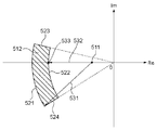
図8により点(-1+j0)から一巡伝達特性の変動範囲までの距離を説明する。感度特性演算部22は、点(-1+j0)から一巡伝達特性の変動範囲までの最長距離と最短距離を演算する。図8において、点511は(-1+j0)の点であり、領域512は一巡伝達特性の変動範囲に相当する。領域512を囲む境界線521はゲインの最大値に、境界線522はゲインが最小値に、境界線523は位相差の最大値に、境界線524は位相差の最小値にそれぞれ対応する。
The distance from the point (−1 + j0) to the fluctuation range of the round transfer characteristic will be described with reference to FIG. The sensitivity
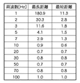
点511が領域512に含まれる場合、安定性判定部15が制御系は不安定と判定するので、ステップS107の処理は実行されない。言い換えれば、制御系が安定な場合、領域512は点511を含まない。従って、点511から領域512の最長距離に対応する点は境界線521上にあり、点511から領域512の最短距離に対応する点は境界線522上にある。図8の例においては、点511から境界線521の下端を結ぶ線分531が最長になり線分531の長さを最長距離とし、点511から境界線522と実数(Re)軸の交点533を結ぶ線分532が最短になり線分532の長さを最短距離とする。図9により最長距離と最短距離のデータの一例を示す。
When the
外乱から制御量までの外乱感度特性は、点511から一巡伝達特性まで距離の逆数として演算される。従って、感度特性演算部22は、点511から一巡伝達特性の変動範囲までの最長距離との逆数を外乱感度特性の最良値、最短距離の逆数を外乱感度特性の最悪値とする外乱感度特性の変動領域を得る。図10により外乱感度特性の最良値と最悪値の一例を示す。
The disturbance sensitivity characteristic from the disturbance to the control amount is calculated as the reciprocal of the distance from the
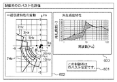
制御系が安定と判定された場合、出力部16は、安定性判定部15から安定性の判定結果を、座標変換部21から一巡伝達特性の変動範囲を、感度特性演算部22から外乱感度特性の変動領域をそれぞれ入力し、それらを出力する(S109)。
When it is determined that the control system is stable, the
図11により制御系が安定と判定された場合の出力部16の出力例を示す。図11は、モニタ113に、安定性の判定結果を文字列601として表示するとともに、周波数に対する一巡伝達特性の変動範囲および外乱感度特性の変動領域をグラフ602、603として表示するUIの一例を示す。
FIG. 11 shows an output example of the
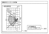
他方、制御系が不安定と判定された場合、出力部16は、安定性判定部15から安定性の判定結果を、座標変換部21から一巡伝達特性の変動範囲をそれぞれ入力し、それらを出力する(S110)。
On the other hand, when it is determined that the control system is unstable, the
図12により制御系が不安定と判定された場合の出力部16の出力例を示す。図12は、モニタ113に、安定性の判定結果を文字列601として表示するとともに、周波数に対する一巡伝達特性の変動範囲をグラフ602として表示するUIの一例を示す。
FIG. 12 shows an output example of the
図11に示すUIを参照するユーザは、表示601から制御系が安定であることを知り、表示602において一巡伝達特性の変動範囲が点(-1+j0)を含まず、同点を左に見ながら回っていることから、制御系は充分に安定であると判断する。さらに、表示603を参照して、外乱感度特性の変動領域が外乱感度特性から制御器の設計変更の必要性を判断する。例えば、ユーザが所望する外乱感度特性が1.5だとすると、10Hzにおける外乱感度特性の最大値は1.78であり、制御器の設計変更が必要になる。つまり、10Hzにおける制御器のゲインを下げるなどして、所望する外乱感度特性を得られるよう設計変更を行う。
The user referring to the UI shown in FIG. 11 knows from the
また、図12に示すUIを参照するユーザは、表示601から制御系が不安定であることを知る。そして、表示602を参照して、3Hzにおける一巡伝達特性の変動範囲が点(-1+j0)を含むために制御系が不安定と判定されたことを理解する。従って、ユーザは、3Hzにおける制御器のゲインを上げるなどして、制御系を安定にする設計変更を行う。
Further, the user who refers to the UI shown in FIG. 12 knows from the
安定性の判定結果を表示するとともに、周波数に対する一巡伝達特性の変動範囲をグラフ表示することで、ユーザは、制御系が不安定の原因を容易に把握することができる。制御系が安定の場合は、加えて、周波数に対する外乱感度特性の変動領域をグラフ表示することで、ユーザは制御系の外乱に対する安定性を容易に把握することができる。これら情報から、ユーザは、制御器の設計変更の必要性を正しく判断することができる。 By displaying the stability determination result and displaying the fluctuation range of the loop transfer characteristic with respect to the frequency in a graph, the user can easily grasp the cause of the instability of the control system. In addition, when the control system is stable, the user can easily grasp the stability of the control system against disturbance by displaying the fluctuation region of the disturbance sensitivity characteristic with respect to the frequency in a graph. From this information, the user can correctly determine the necessity of the controller design change.
また、周波数ごとの一巡伝達特性の表示により、ユーザは、制御精度が不足する周波数帯域や不安定な周波数帯域を把握することができる。さらに、周波数ごとの外乱感度特性の表示により、ユーザは、制御系の外乱感度特性を漏れなく評価することができる。例えば、所望の制御精度が得られるか、所望の制御精度が得られない周波数帯域は何処か、などを判断することができる。従って、ユーザは、制御器の設計変更を行う際に注目すべき周波数帯域を把握して、速度変動に対する抑制力を強くするなどして、所望の制御精度が得られる制御系を構築することができる。 Further, the display of the round transfer characteristics for each frequency enables the user to grasp a frequency band where control accuracy is insufficient or an unstable frequency band. Furthermore, the display of the disturbance sensitivity characteristic for each frequency enables the user to evaluate the disturbance sensitivity characteristic of the control system without omission. For example, it can be determined whether a desired control accuracy is obtained or where a frequency band in which a desired control accuracy cannot be obtained is obtained. Therefore, a user can construct a control system that can obtain desired control accuracy by grasping a frequency band to be noticed when making a design change of the controller and strengthening a suppression force against speed fluctuation. it can.
このように、実施例の評価装置の制御系の評価処理によれば、ロバスト制御系の安定性を漏れなく評価することができる。その結果、ユーザは、制御器の設計変更の必要性を精度よく、かつ、簡単に判断することができ、使用環境において安定性を確保しつつ、所望する制御精度が得られる制御系を構築することができる。 Thus, according to the control system evaluation process of the evaluation apparatus of the embodiment, the stability of the robust control system can be evaluated without omission. As a result, the user can accurately and easily determine the necessity of the controller design change, and build a control system that can obtain the desired control accuracy while ensuring stability in the usage environment. be able to.
以上では、画像形成装置の感光体の駆動制御における制御系の評価装置について説明したが、本実施例は、画像形成装置の他の駆動制御系、プラントの温度制御系などにも適用することができる。また、経年劣化により制御対象の伝達特性が時系列変動する場合は、当該変動を周波数特性のゲインと位相差の変動に変換することで、当該制御系にも本実施例を適用することができる。 Although the control system evaluation apparatus in the drive control of the photosensitive member of the image forming apparatus has been described above, the present embodiment can be applied to other drive control systems of the image forming apparatus, temperature control systems of plants, and the like. it can. In addition, when the transfer characteristic of the control target fluctuates in time series due to deterioration over time, the present embodiment can be applied to the control system by converting the fluctuation into a gain of the frequency characteristic and a fluctuation of the phase difference. .
[その他の実施例]
また、本発明は、以下の処理を実行することによっても実現される。即ち、上述した実施形態の機能を実現するソフトウェア(プログラム)を、ネットワーク又は各種記憶媒体を介してシステム或いは装置に供給し、そのシステムあるいは装置のコンピュータ(又はCPUやMPU等)がプログラムを読み出して実行する処理である。
[Other Examples]
The present invention can also be realized by executing the following processing. That is, software (program) that realizes the functions of the above-described embodiments is supplied to a system or apparatus via a network or various storage media, and a computer (or CPU, MPU, etc.) of the system or apparatus reads the program. It is a process to be executed.
Claims (6)
前記制御器の周波数特性を取得する第一の取得手段と、
前記制御対象のゲイン特性および位相差特性を取得する第二の取得手段と、
複素座標系において、前記ゲイン特性の変動範囲と前記位相差特性の変動範囲が重なる領域を前記制御対象の周波数特性の変動範囲として、前記周波数特性の変動範囲と前記制御器の周波数特性から前記制御系の一巡伝達特性とその変動範囲を演算する一巡伝達特性の演算手段と、
前記一巡伝達特性とその変動範囲から前記制御系の安定性を評価する評価手段とを有することを特徴とする評価装置。 An evaluation device for evaluating a control system having a controller and a control object,
First acquisition means for acquiring frequency characteristics of the controller;
Second acquisition means for acquiring the gain characteristic and phase difference characteristic of the controlled object;
In a complex coordinate system, a region where the fluctuation range of the gain characteristic and the fluctuation range of the phase difference characteristic overlap is set as a fluctuation range of the frequency characteristic of the control target, and the control is performed from the fluctuation range of the frequency characteristic and the frequency characteristic of the controller. A round-trip transfer characteristic calculation means for calculating a round-trip transfer characteristic of the system and its fluctuation range;
An evaluation apparatus comprising: an evaluation unit that evaluates the stability of the control system based on the round transfer characteristic and a variation range thereof.
前記出力手段は、さらに前記外乱感度特性の変動領域を出力することを特徴とする請求項2に記載された評価装置。 The evaluation means further calculates a disturbance sensitivity characteristic fluctuation region for calculating a fluctuation area of the disturbance sensitivity characteristic from a fluctuation range of the round transfer characteristic converted into the complex coordinate system when the determination means determines that the control system is stable. Having a computing means of
3. The evaluation apparatus according to claim 2, wherein the output unit further outputs a fluctuation region of the disturbance sensitivity characteristic.
前記第一の取得手段が、前記制御器の周波数特性を取得し、
前記第二の取得手段が、前記制御対象のゲイン特性および位相差特性を取得し、
前記演算手段が、複素座標系において、前記ゲイン特性の変動範囲と前記位相差特性の変動範囲が重なる領域を前記制御対象の周波数特性の変動範囲として、前記周波数特性の変動範囲と前記制御器の周波数特性から前記制御系の一巡伝達特性とその変動範囲を演算し、
前記評価手段が、前記一巡伝達特性とその変動範囲から前記制御系の安定性を評価することを特徴とする評価方法。 An evaluation method for an evaluation apparatus for evaluating a control system having a first and second acquisition means, a calculation means, and an evaluation means, and having a controller and a control object
The first acquisition means acquires a frequency characteristic of the controller;
The second acquisition means acquires the gain characteristic and phase difference characteristic of the control target,
In the complex coordinate system, the calculation means uses a region in which the variation range of the gain characteristic and the variation range of the phase difference characteristic overlap as a variation range of the frequency characteristic of the control target, and the variation range of the frequency characteristic and the controller From the frequency characteristics, calculate the round trip transmission characteristics of the control system and its fluctuation range,
The evaluation method characterized in that the evaluation means evaluates the stability of the control system from the round transfer characteristic and its fluctuation range.
Priority Applications (2)
| Application Number | Priority Date | Filing Date | Title |
|---|---|---|---|
| JP2011093511A JP5836628B2 (en) | 2011-04-19 | 2011-04-19 | Control system evaluation apparatus, evaluation method, and program |
| US13/421,973 US9075403B2 (en) | 2011-04-19 | 2012-03-16 | Estimation apparatus for control system and method therefor |
Applications Claiming Priority (1)
| Application Number | Priority Date | Filing Date | Title |
|---|---|---|---|
| JP2011093511A JP5836628B2 (en) | 2011-04-19 | 2011-04-19 | Control system evaluation apparatus, evaluation method, and program |
Publications (2)
| Publication Number | Publication Date |
|---|---|
| JP2012226550A JP2012226550A (en) | 2012-11-15 |
| JP5836628B2 true JP5836628B2 (en) | 2015-12-24 |
Family
ID=47021937
Family Applications (1)
| Application Number | Title | Priority Date | Filing Date |
|---|---|---|---|
| JP2011093511A Active JP5836628B2 (en) | 2011-04-19 | 2011-04-19 | Control system evaluation apparatus, evaluation method, and program |
Country Status (2)
| Country | Link |
|---|---|
| US (1) | US9075403B2 (en) |
| JP (1) | JP5836628B2 (en) |
Families Citing this family (1)
| Publication number | Priority date | Publication date | Assignee | Title |
|---|---|---|---|---|
| JP2023031904A (en) * | 2021-08-26 | 2023-03-09 | いすゞ自動車株式会社 | Information processing apparatus |
Family Cites Families (15)
| Publication number | Priority date | Publication date | Assignee | Title |
|---|---|---|---|---|
| US6311136B1 (en) * | 1997-11-26 | 2001-10-30 | Invensys Systems, Inc. | Digital flowmeter |
| JP3219245B2 (en) * | 1998-08-13 | 2001-10-15 | 株式会社日立国際電気 | Temperature control simulation method and temperature control simulation device |
| JP4144378B2 (en) * | 2003-02-28 | 2008-09-03 | ソニー株式会社 | Image processing apparatus and method, recording medium, and program |
| US7031095B2 (en) * | 2004-07-29 | 2006-04-18 | Samsung Electronics Co., Ltd. | Servo controller method and apparatus for high tracks per inch hard disk drives using a delay accomodating state estimator |
| US7532679B2 (en) * | 2004-08-12 | 2009-05-12 | Texas Instruments Incorporated | Hybrid polar/cartesian digital modulator |
| US7643602B2 (en) * | 2005-09-30 | 2010-01-05 | Freescale Semiconductor, Inc. | Method and system for estimating frequency offsets |
| JP4751192B2 (en) * | 2005-12-12 | 2011-08-17 | 本田技研工業株式会社 | Mobile robot |
| US8179753B2 (en) * | 2006-05-17 | 2012-05-15 | Nec Corporation | Positioning control unit and optical disk drive |
| US7617055B2 (en) * | 2006-08-28 | 2009-11-10 | Invensys Systems, Inc. | Wet gas measurement |
| US8185853B2 (en) * | 2007-04-11 | 2012-05-22 | Rambus Inc. | Transforming variable domains for linear circuit analysis |
| US7912664B2 (en) * | 2008-09-11 | 2011-03-22 | Northrop Grumman Guidance And Electronics Company, Inc. | Self calibrating gyroscope system |
| JP5206378B2 (en) * | 2008-12-05 | 2013-06-12 | ソニー株式会社 | Information processing apparatus, information processing method, and program |
| JP5593608B2 (en) * | 2008-12-05 | 2014-09-24 | ソニー株式会社 | Information processing apparatus, melody line extraction method, baseline extraction method, and program |
| JP4810582B2 (en) * | 2009-03-26 | 2011-11-09 | 株式会社東芝 | Mobile object image tracking apparatus and method |
| TWI412730B (en) * | 2009-06-08 | 2013-10-21 | Wistron Corp | Methods and device for detecting distance, identifying positions of targets, and identifying a current position in a smart portable device |
-
2011
- 2011-04-19 JP JP2011093511A patent/JP5836628B2/en active Active
-
2012
- 2012-03-16 US US13/421,973 patent/US9075403B2/en active Active
Also Published As
| Publication number | Publication date |
|---|---|
| JP2012226550A (en) | 2012-11-15 |
| US20120271438A1 (en) | 2012-10-25 |
| US9075403B2 (en) | 2015-07-07 |
Similar Documents
| Publication | Publication Date | Title |
|---|---|---|
| Ge et al. | Impedance adaptation for optimal robot–environment interaction | |
| Tang et al. | Differential evolution strategy for structural system identification | |
| Mittal et al. | Topological characterization and early detection of bifurcations and chaos in complex systems using persistent homology | |
| US10967505B1 (en) | Determining robot inertial properties | |
| JP7090734B2 (en) | Control system, control method and storage medium | |
| JP6443165B2 (en) | State estimation method and state estimation device | |
| JP7014095B2 (en) | Setting support device | |
| JP5836628B2 (en) | Control system evaluation apparatus, evaluation method, and program | |
| JP2010266967A (en) | PID adjustment device and PID adjustment program | |
| Marques Monteiro et al. | Visuo-dynamic self-modelling of soft robotic systems | |
| Álvarez et al. | Perspectives on control-relevant identification through the use of interactive tools | |
| McDaid et al. | Gain scheduled control of IPMC actuators with ‘model-free’iterative feedback tuning | |
| CN105095555B (en) | It is a kind of based on particle image velocimetry method and device of the velocity field without scattered smoothing processing | |
| Bian et al. | Improving stability in physical human–robot interaction by estimating human hand stiffness and a vibration index | |
| JP5749041B2 (en) | Active feedback control device and program | |
| Ogbemhe et al. | Robot dynamic model: freudenstein-based optimal trajectory and parameter identification | |
| JP5298603B2 (en) | Crystal grain analysis apparatus, crystal grain analysis method, and computer program | |
| US10496096B2 (en) | Real time effective mass and moment of inertia measurement | |
| JP5114674B2 (en) | Crystal grain analysis apparatus, crystal grain analysis method, and computer program | |
| JP7014094B2 (en) | Setting support device | |
| JP5375019B2 (en) | Crystal grain analysis apparatus, crystal grain analysis method, and computer program | |
| VanDoren | Fundamentals of lambda tuning | |
| Srikanth | Linear Function Approximation as a Computationally Efficient Method to Solve Classical Reinforcement Learning Challenges | |
| JP5807732B2 (en) | Performance prediction apparatus, performance prediction method, and performance prediction program | |
| CN108241569B (en) | A user experience benchmarking system and implementation method based on remote visualization technology |
Legal Events
| Date | Code | Title | Description |
|---|---|---|---|
| A621 | Written request for application examination |
Free format text: JAPANESE INTERMEDIATE CODE: A621 Effective date: 20140416 |
|
| A977 | Report on retrieval |
Free format text: JAPANESE INTERMEDIATE CODE: A971007 Effective date: 20150212 |
|
| A131 | Notification of reasons for refusal |
Free format text: JAPANESE INTERMEDIATE CODE: A131 Effective date: 20150302 |
|
| A521 | Written amendment |
Free format text: JAPANESE INTERMEDIATE CODE: A523 Effective date: 20150427 |
|
| TRDD | Decision of grant or rejection written | ||
| A01 | Written decision to grant a patent or to grant a registration (utility model) |
Free format text: JAPANESE INTERMEDIATE CODE: A01 Effective date: 20151005 |
|
| A61 | First payment of annual fees (during grant procedure) |
Free format text: JAPANESE INTERMEDIATE CODE: A61 Effective date: 20151104 |
|
| R151 | Written notification of patent or utility model registration |
Ref document number: 5836628 Country of ref document: JP Free format text: JAPANESE INTERMEDIATE CODE: R151 |