JP5835938B2 - Aberration correction method, fundus imaging method using the method, and fundus imaging apparatus - Google Patents
Aberration correction method, fundus imaging method using the method, and fundus imaging apparatus Download PDFInfo
- Publication number
- JP5835938B2 JP5835938B2 JP2011105386A JP2011105386A JP5835938B2 JP 5835938 B2 JP5835938 B2 JP 5835938B2 JP 2011105386 A JP2011105386 A JP 2011105386A JP 2011105386 A JP2011105386 A JP 2011105386A JP 5835938 B2 JP5835938 B2 JP 5835938B2
- Authority
- JP
- Japan
- Prior art keywords
- aberration
- eye
- amount
- examined
- imaging
- Prior art date
- Legal status (The legal status is an assumption and is not a legal conclusion. Google has not performed a legal analysis and makes no representation as to the accuracy of the status listed.)
- Expired - Fee Related
Links
Images


Classifications
-
- A—HUMAN NECESSITIES
- A61—MEDICAL OR VETERINARY SCIENCE; HYGIENE
- A61B—DIAGNOSIS; SURGERY; IDENTIFICATION
- A61B3/00—Apparatus for testing the eyes; Instruments for examining the eyes
- A61B3/10—Objective types, i.e. instruments for examining the eyes independent of the patients' perceptions or reactions
- A61B3/12—Objective types, i.e. instruments for examining the eyes independent of the patients' perceptions or reactions for looking at the eye fundus, e.g. ophthalmoscopes
-
- A—HUMAN NECESSITIES
- A61—MEDICAL OR VETERINARY SCIENCE; HYGIENE
- A61B—DIAGNOSIS; SURGERY; IDENTIFICATION
- A61B3/00—Apparatus for testing the eyes; Instruments for examining the eyes
- A61B3/10—Objective types, i.e. instruments for examining the eyes independent of the patients' perceptions or reactions
- A61B3/14—Arrangements specially adapted for eye photography
Landscapes
- Life Sciences & Earth Sciences (AREA)
- Health & Medical Sciences (AREA)
- Medical Informatics (AREA)
- Biophysics (AREA)
- Ophthalmology & Optometry (AREA)
- Engineering & Computer Science (AREA)
- Biomedical Technology (AREA)
- Heart & Thoracic Surgery (AREA)
- Physics & Mathematics (AREA)
- Molecular Biology (AREA)
- Surgery (AREA)
- Animal Behavior & Ethology (AREA)
- General Health & Medical Sciences (AREA)
- Public Health (AREA)
- Veterinary Medicine (AREA)
- Eye Examination Apparatus (AREA)
Description
本発明は、眼底撮像方法、および眼底撮像装置に関し、特に、被検眼の収差を測定して補正する補償光学機能を有し、撮像画像の取得状況に応じて収差を補正する収差補正方法および該方法により収差の補正が可能な眼底撮像方法、および眼底撮像装置に関する。 The present invention relates to a fundus imaging method and a fundus imaging apparatus, and in particular, has an adaptive optical function for measuring and correcting aberrations of an eye to be examined, and an aberration correction method for correcting aberrations according to the acquisition state of a captured image, and the The present invention relates to a fundus imaging method capable of correcting aberrations and a fundus imaging apparatus.
近年、眼科用の撮像装置として、眼底に2次元的にレーザ光を照射してその反射光を受光して画像化するSLO(Scanning Laser Ophthalmoscope:走査レーザ検眼鏡)や、低コヒーレンス光の干渉を利用したイメージング装置が開発されている。低コヒーレンス光の干渉を利用したイメージング装置は、OCT(Optical Coherence Tomography:光干渉断層装置あるいは光干渉断層法)と呼ばれ、特に、眼底あるいはその近傍の断層像を得る目的で用いられている。OCTの種類としては、TD−OCT(Time Domain OCT:タイムドメイン法)や、SD−OCT(Spectral Domain OCT:スペクトラルドメイン法)等を含め、種々のものが開発されてきている。 In recent years, as an ophthalmic imaging apparatus, scanning laser opthalmoscope (SLO) that irradiates laser light two-dimensionally on the fundus and receives the reflected light to form an image, and interference of low coherence light. Utilized imaging devices have been developed. An imaging device using low-coherence light interference is called OCT (Optical Coherence Tomography), and is used particularly for the purpose of obtaining a tomographic image of the fundus or its vicinity. Various types of OCT have been developed, including TD-OCT (Time Domain OCT: Time Domain Method) and SD-OCT (Spectral Domain OCT: Spectral Domain Method).
特に、このような眼科用の撮像装置は、近年において、照射レーザの高NA化等によってさらなる高解像度化が進められている。 In particular, in such an ophthalmic imaging apparatus, in recent years, higher resolution has been promoted by increasing the NA of an irradiation laser.
しかしながら、眼底を撮像する場合には、角膜や水晶体等の眼の光学組織を通して撮像をしなければならない。そのため、高解像度化が進むに連れて、これら角膜や水晶体の収差が撮像画像の画質に大きく影響するようになってきた。 However, when imaging the fundus, the image must be captured through the optical tissue of the eye such as the cornea or the crystalline lens. For this reason, as the resolution increases, the aberrations of the cornea and the crystalline lens greatly affect the image quality of the captured image.
そこで、眼の収差を測定し、その収差を補正する補償光学(Adaptive Optics:AO)機能を光学系に組み込んだ、AO−SLOやAO−OCTの研究が進められている。例えば、非特許文献1に、AO−OCTの例が示されている。これらAO−SLOやAO−OCTは、一般的にはシャックハルトマン波面センサー方式によって眼の波面を測定する。シャックハルトマン波面センサー方式とは、眼に測定光を入射し、その反射光をマイクロレンズアレイを通してCCDカメラに受光することによって波面を測定するものである。測定した波面を補正するように可変形状ミラーや、空間位相変調器を駆動し、それらを通して眼底の撮像を行うことにより、AO−SLOやAO−OCTは高解像度な撮像が可能となる。
Therefore, research on AO-SLO and AO-OCT in which an adaptive optics (AO) function for measuring aberrations of an eye and correcting the aberrations is incorporated in an optical system has been underway. For example, Non-Patent
眼科装置に用いるAOにおいては、一般的に波面センサーで測定した収差をZernike関数のような関数でモデル化し、その関数を用いて波面補正器の補正量を計算する。複雑な形状を補正するためには、多くの次数を持つ関数で収差をモデル化して補正量を算出し、波面補正器を制御する必要がある。 In AO used in an ophthalmologic apparatus, the aberration measured by a wavefront sensor is generally modeled by a function such as a Zernike function, and the correction amount of the wavefront corrector is calculated using the function. In order to correct a complicated shape, it is necessary to control the wavefront corrector by modeling the aberration with a function having many orders and calculating the correction amount.
しかし、補正量を算出することは非常に計算負荷が高く、計算時間の増大が大きな問題となっている。特に、眼科装置に対しては、病気の経過観察を行うために定期的に患部の観察を行うことが求められているため、撮像時間を少しでも短縮することが眼科医療の効率を向上させるためには不可欠となっている。 However, calculating the correction amount has a very high calculation load, and an increase in calculation time is a serious problem. In particular, ophthalmic devices are required to periodically observe the affected area in order to monitor the progress of illness, so shortening the imaging time as much as possible improves the efficiency of ophthalmic medicine. Is indispensable.
本発明は、上記課題に鑑み、AOを用いる眼科装置において、眼の収差補正に要する時間を短縮することを目的とする。 In view of the above problems, an object of the present invention is to reduce the time required for correcting eye aberration in an ophthalmologic apparatus using AO.
上記課題を解決するために、本発明に係る収差補正方法は、
被検眼の収差を収差補正手段により補正する収差補正方法であって、
記憶手段に記憶された前記被検眼の収差量と前記収差量が測定された前記被検眼の眼底の領域とが対応付けられた情報に基づいて、撮像手段による撮像領域に対応する収差量が前記記憶手段に記憶されているか否かを判定手段により判定する判定工程と、
選択手段によって、前記撮像領域に対応する収差量が前記記憶手段に記憶されている場合には前記撮像領域に対応する収差量を選択し、且つ前記撮像領域に対応する収差量が前記記憶手段に記憶されていない場合には前記記憶手段に予め記憶されている収差量を選択する選択工程と、
選択された前記撮像領域に対応する収差量或いは前記予め記憶されている収差量に基づいて、前記収差補正手段により前記被検眼の収差の補正を行う補正工程と、
を有することを特徴とする。
In order to solve the above problems, the aberration correction method according to the present invention is:
A aberration correction method for correcting the aberration correcting means aberration of the test eye,
Based on the aberration amount of the subject's eye that is stored in the storage means and said aberration is measured fundus region of the eye to be examined has been is associated information, aberration amount corresponding to the imaging region by the imaging means the A determination step of determining by the determination means whether or not stored in the storage means ;
By the selecting means, before Symbol if the aberration amount corresponding to the imaging area is stored in the storage means to select the aberration amount corresponding to the imaging area, and the aberration amount corresponding to the imaging region said storage means a selection step of selecting aberration amount is previously stored in the storage unit when not stored in,
Aberration amount corresponding to the selected the imaging regions or on the basis of the aberration amount the stored beforehand, and a correction step of correcting the aberration of the subject's eye by the aberration correcting means,
It is characterized by having.
本発明によれば、前回撮影したときの情報を利用することにより、収差補正を高速化することが可能となり、診察に要する時間を短縮することが可能となる。 According to the present invention, it is possible to speed up the aberration correction by using the information at the time of previous photographing, and it is possible to shorten the time required for the examination.
本発明を実施するための形態を、以下の実施例により説明する。但し、本発明は以下の実施例の構成によって何ら限定されるものではない。 The mode for carrying out the present invention will be described with reference to the following examples. However, the present invention is not limited to the configurations of the following examples.
実施例1として、本発明を適用した眼底撮像装置の構成について図1を用いて説明する。
なお、本実施例においては、測定対象である被検査物を眼とし、眼で発生する収差を補償光学系で補正し、眼底を撮像するようにした一例について説明する。
As Example 1, a configuration of a fundus imaging apparatus to which the present invention is applied will be described with reference to FIG.
In the present embodiment, an example will be described in which an object to be inspected as an object to be measured is an eye, an aberration generated in the eye is corrected by the compensation optical system, and the fundus is imaged.
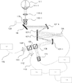
図1において、101は光源であり、波長840nmのSLD光源(Super Luminescent Diode)を用いた。光源101の波長は特に制限されるものではないが、眼底撮像用としては被検者の眩しさの軽減と解像度維持のために、800〜1500nm程度が好適に用いられる。本実施例においてはSLD光源を用いたが、その他にレーザ等も用いられる。本実施例では眼底撮像と波面測定のための光源を共用しているが、それぞれを別光源とし、光路の途中で合波する構成としても良い。
In FIG. 1, 101 is a light source, and an SLD light source (Super Luminescent Diode) having a wavelength of 840 nm was used. Although the wavelength of the
光源101から照射された光は、単一モード光ファイバー102を通って、コリメータ103により、平行光線(測定光105)として照射される。
The light emitted from the
照射された測定光105はビームスプリッタからなる光分割部104を透過し、補償光学の光学系に導光される。
The
補償光学系は、光分割部106、波面センサー115、波面補正デバイス108および、それらに導光するための反射ミラー107−1〜4から構成される。
ここで、反射ミラー107−1〜4は、少なくとも眼111の瞳と波面センサー115、波面補正デバイス108とが光学的に共役関係になるように設置されている。また、光分割部106として、本実施例ではビームスプリッタを用いた。
The compensation optical system includes a
Here, the reflection mirrors 107-1 to 107-4 are installed so that at least the pupil of the
光分割部106を透過した測定光105は、反射ミラー107−1と107−2で反射されて波面補正デバイス108に入射する。波面補正デバイス108で反射された測定光105は、反射ミラー107−3に出射される。
The
本実施例では、波面補正デバイス108として液晶素子を用いた空間位相変調器を用いた。図2に反射型液晶光変調器の模式図を示す。本変調器はベース部122とカバー123に挟まれた空間に液晶分子125が封入されている構造となっている。ベース部122には複数の画素電極124を有し、カバー123には不図示の透明な対向電極を有している。電極間に電圧を印加していない場合には、液晶分子は125−1のような配向をしており、電圧を印加すると125−2のような配向状態に遷移し、入射光に対する屈折率が変化する。各画素電極の電圧を制御して各画素の屈折率を変化させることにより、空間的な位相変調が可能となる。例えば入射光126が本変調器に入射した場合、液晶分子125−2を通過する光は液晶分子125−1を通過する光よりも位相が遅れ、結果として図中127で示すような波面を形成する。一般的に反射型液晶光変調器は、数万〜数十万個の画素から構成されている。また、液晶光変調器は偏光特性を有するため、入射光の偏光を調整するための偏光素子を具備することもある。
In this embodiment, a spatial phase modulator using a liquid crystal element is used as the
波面補正デバイス108の他の例としては、可変形状ミラーがある。可変形状ミラーとは、局所的に光の反射方向を変えることができるものであり、様々な方式のものが実用化されている。その一例として、他の波面補正デバイス108の断面を図3に示す。入射光を反射する変形可能な膜状のミラー面129と、ベース部128と、これらに挟まれて配置されたアクチュエータ130と、ミラー面129を周囲から支持する不図示の支持部から構成されている。アクチュエータ130の動作原理としては、静電力や磁気力、圧電効果を利用したものがあり、動作原理によってアクチュエータ130の構成は異なる。アクチュエータ130はベース部128上に二次元的に複数配列されていて、それらを選択的に駆動することにより、ミラー面129を自在に変形できるようになっている。一般的に可変形状ミラーは数十〜数百のアクチュエータで構成されている。
Another example of the
図1において、反射ミラー107−3、4で反射された光は、走査光学系109によって、1次元もしくは2次元に走査される。本実施例では走査光学系109に主走査用(眼底水平方向)と副走査用(眼底垂直方向)として2つのガルバノスキャナーを用いた。より高速な撮像のために、走査光学系109の主走査用に共振スキャナーを用いることもある。走査光学系109内の各スキャナーを光学的な共役状態にするために、各スキャナーの間にミラーやレンズといった光学素子を用いる装置構成の場合もある。図9は眼底撮像装置が、被検眼の眼底を分割して撮像する様子を示したもので、161は眼底の2次元画像であり、162は黄斑、163は視神経乳頭である。164は眼底161を格子状に分割した状態を表したもので、水平方向、垂直方向にはそれぞれa〜p、1〜16のアドレスが割り振られており、眼底は16×16の256個に分割されて領域毎に撮像される。更に、格子一つは、走査光学系109により、主走査方向、副走査方向それぞれに、3μm角の画素256×256に分割されて読み取られる。
In FIG. 1, the light reflected by the reflection mirrors 107-3 and 4 is scanned one-dimensionally or two-dimensionally by the scanning
走査光学系109で走査された測定光105は、接眼レンズ110−1および110−2を通して眼111に照射される。111−1は、眼のレンズに相当する水晶体である。眼111に照射された測定光は眼底で反射もしくは散乱される。接眼レンズ110−1および110−2の位置を調整することによって、眼111の視度にあわせて最適な照射を行うことが可能となる。ここでは、接眼部にレンズを用いたが、球面ミラー等で構成しても良い。
The
119はビームスプリッタである光分光器、120は固視灯である。ビームスプリッタ119は、被検眼に対して固視灯120からの光を、測定光105と共に被検眼に導くものである。固視灯120は、被検者に対して視線をどこに向けるかを指示するためのもので、液晶ディスプレイ、LEDを平面に格子状に並べたもの等で構成される。図7に、固視灯120を構成する液晶ディスプレイ141の拡大図を示す。図7に示すように、液晶ディスプレイ141上には142で示されるような十字形が点灯される。被検者には、十字形142の交点を見てもらうことにより、被検眼の動きを停止させることができる。また、十字形142の点灯位置を、液晶ディスプレイ141上で上下左右に移動させることにより、被検者の視線をコントロールし、被検眼の所望の領域を観察することが可能となる。
119 is an optical spectroscope that is a beam splitter, and 120 is a fixation lamp. The
眼111の網膜から反射もしくは散乱された反射光は、入射した時の経路を逆向きに進行し、光分割部106によって一部は波面センサー115に反射され、光線の波面を測定するために用いられる。
The reflected light reflected or scattered from the retina of the
本実施例では、波面センサー115としてシャックハルトマンセンサーを用いた。図4にシャックハルトマンセンサーの模式図を示す。131が波面を測定する光線であり、マイクロレンズアレイ132を通して、CCDセンサー133上の焦点面134に集光される。図4の(a)のA-A‘で示す位置から見た様子を示す図が図4の(b)であり、マイクロレンズアレイ132が、複数のマイクロレンズ135から構成されている様子を示したものである。光線131は各マイクロレンズ135を通してCCDセンサー133上に集光されるため、光線131はマイクロレンズ135の個数分のスポットに分割されて集光される。図5にCCDセンサー133上に集光された状態を示す。各マイクロレンズを通過した光線はスポット136に集光される。そして、この各スポット136の位置から、入射した光線の波面を計算する。図6(a)に球面収差を持つ波面を測定した場合の模式図を示す。光線131は137で示すような波面で形成されている。光線131はマイクロレンズアレイ132によって、波面の局所的な垂線方向の位置に集光される。この場合のCCDセンサー133の集光状態を図6(b)に示す。光線131が球面収差を持つため、スポット136は中央部に偏った状態で集光される。この位置を計算することによって、光線131の波面が検出できる。本実施例では波面センサーにシャックハルトマンセンサーを用いたが、それに限定されるものではなく、曲率センサーのような他の波面測定手段や、結像させた点像から逆計算で求めるような方法を用いても良い。
In this embodiment, a Shack-Hartmann sensor is used as the
図1において、光分割部106を透過した反射光は光分割部104によって一部が反射され、コリメータ112、光ファイバー113を通して光強度センサー114に導光される。光強度センサー114で光は電気信号に変換され、制御部117によって眼底画像として画像に構成されて、ディスプレイ118に表示される。
In FIG. 1, a part of the reflected light transmitted through the
波面センサー115は、補償光学制御部116に接続され、受光した波面を補償光学制御部116に伝える。波面補正デバイス108も補償光学制御部116に接続されており、補償光学制御部116から指示された変調を行う。補償光学制御部116は波面センサー115の測定結果による取得された波面を基に、収差のない波面へと補正するような変調量(補正量)を計算し、波面補正デバイス108にそのように変調するように指令する。波面の測定と波面補正デバイスへの指示は繰り返し処理され、常に最適な波面となるようにフィードバック制御が行われる。
The
本実施例では、測定した波面をZernike関数にモデル化して各次数にかかる係数を算出し、その係数を元に波面補正デバイス108の変調量を算出する。変調量の算出においては、波面補正デバイスがZernike各次数の形状を形成するための基準変調量を元に、測定された全てのZernike次数の係数に関して基準変調量を乗算し、さらにそれらをすべて積算することによって最終的な変調量を得る。
In the present embodiment, the measured wavefront is modeled as a Zernike function to calculate a coefficient for each order, and the modulation amount of the
以上のように、本発明では、収差量としてこれに対応する波面を所定の関数であるZernike関数を用いて表すこととする。なお、Zernike関数は一例であり、波面を表す他の種々の関数を用いることも可能である。 As described above, in the present invention, the wavefront corresponding to the aberration amount is expressed using the Zernike function which is a predetermined function. The Zernike function is an example, and various other functions representing the wavefront can be used.
また、本実施例では波面補正デバイス108として画素数600×600の反射型液晶空間位相変調器を用いたので、360000画素それぞれの変調量を上記の算出方法に従って算出する。例えばZernike関数の1次〜4次までの係数を用いた計算を行う場合には、Z1-1、Z1+1、Z2-2、Z2-0、Z2+2、Z3-3、Z3-1、Z3+1、Z3+3、Z4-4、Z4-2、Z4-0、Z4+2、Z4+4の14の係数に関して基準変調量との乗算を、上記360000画素に対して行う。また、Zernike関数の1次〜6次までの係数を用いた計算を行う場合には、Z1-1、Z1+1、Z2-2、Z2-0、Z2+2、Z3-3、Z3-1、Z3+1、Z3+3、Z4-4、Z4-2、Z4-0、Z4+2、Z4+4、Z5-5、Z5-3、Z5-1、Z5+1、Z5+3、Z5+5、Z6-6、Z6-4、Z6-2、Z6-0、Z6+2、Z6+4、Z6+6の27の係数に関して基準変調量との乗算を、上記360000画素に対して行う。眼の収差の大部分を占めるのは、近視や遠視、乱視といった低次の収差であるが、それ以外に眼の光学系の微小な凹凸や涙液層の乱れに起因するより高次の収差が存在する。眼の収差をZernike関数系で表現する場合、近視、遠視や乱視であるZernike2次関数が大部分を占め、Zernike3次関数やZernike4次関数が若干含まれ、さらにはZernike5次や6次といった高次の関数がわずかに含まれる。Zernike1〜4次関数は、近視、遠視や乱視が急激に進むような場合を除いては、時間が経過しても大きな部分はあまり変化しない。また、収差の原因が近視、遠視や乱視である場合、Zernike1〜4次関数は、撮像する領域が近接している場合には、領域間で大きな差は生じない。
In this embodiment, since the reflection type liquid crystal spatial phase modulator having 600 × 600 pixels is used as the
以上述べたように、本発明においては、波面計測により得られる収差量は所定の関数によって表され、且つその場合高次関数により示される収差量は計算速度等の観点から含まないことが好ましい。また、計算上除外する次数は5次以上の高次の関数とすることがより好ましい。光学系の一部に被検眼が含まれていることで光学系が不確定な状態であるため、一般的に1回の収差測定と補正では低い収差の波面に到達することは困難で、収差測定と補正を繰り返して撮像可能な収差まで補正する。 As described above, in the present invention, it is preferable that the amount of aberration obtained by wavefront measurement is represented by a predetermined function, and in that case, the amount of aberration indicated by a high-order function is not included from the viewpoint of calculation speed and the like. Further, it is more preferable that the order excluded in the calculation is a higher-order function of 5th order or higher. Since the optical system is indeterminate because the eye to be examined is included in a part of the optical system, it is generally difficult to reach the wavefront of low aberration with one aberration measurement and correction. Repeat the measurement and correction to correct aberrations that can be imaged.
図1に示された眼底撮像装置はすべて不図示のコントローラで制御される。図8はコントローラのブロック図である。図8に示すように、コントローラ151は、CPU152、I/O制御部153、メモリ154で構成されている。CPU152では、CPU152に内蔵されるプログラムに従って、眼底撮像装置を制御する。メモリ154には、既に眼底撮像装置で撮像した被検者の眼の収差情報が、被検眼の撮像領域ごとに格納されている。具体的には、被検者のIDと図9の165で示したような撮像領域のアドレス(f、6)、更にその領域を撮像した時の収差量が格納される。
All of the fundus imaging apparatus shown in FIG. 1 are controlled by a controller (not shown). FIG. 8 is a block diagram of the controller. As illustrated in FIG. 8, the
I/O制御部153では、CPU152からの命令に従って、不図示のマウス、キーボード、バーコードリーダ、走査光学系109、補償光学制御部116、制御部117等を駆動、もしくは通信制御する。
The I /
以上のような構成の眼底撮像装置において、本発明の動作を図10のフローチャートを用いて説明する。最初に、図示しないマウス、キーボード、更にはバーコードリーダ等を用い、被検者に対する被検眼の撮像領域を指定する(ステップ101、以下S101)。ここで、この被検者に対して、S101で指定した撮像領域を撮像したことがあるか否かを判断する(S102)。該ステップにより為される工程は、本発明における被検眼の収差に関する情報が予め記憶されているか否かを判定する工程に対応し、該工程はコントローラ151において本発明における判定手段として機能する領域により実行される。過去に指定した領域の撮像をしたことがある場合、すなわち指定した領域の収差情報がメモリ154に格納されている場合には、指定した領域に対する前回撮像した時の収差量、すなわちZernike関数にモデル化して各次数にかかる係数を補償光学制御部116にセットする(S103)。また、指定した領域の撮像を過去にしたことが無い場合、すなわち指定した領域の収差情報がメモリ154に格納されていない場合には、予め設定されている基準収差量および該収差量に関する情報を補償光学制御部116にセットする(S104)。この被検者の撮像が初めての場合にも、指定した領域を過去に撮像したことが無い場合と同様に処理される。なお、以上の工程は、本発明における、被検眼の収差に関する情報が予め記憶されている場合には該情報を選択し、且つ記憶されていない場合には該情報とは異なる他の情報を選択する工程に対応し、当該工程はコントローラ151における選択手段として機能する領域により実行される。
In the fundus imaging apparatus configured as described above, the operation of the present invention will be described using the flowchart of FIG. First, an imaging region of the eye to be examined for the subject is designated using a mouse, keyboard, or barcode reader (not shown) (
次に補償光学制御部116は、セットされた収差量を補正するような変調量(補正量)を計算し(S105)、波面補正デバイス108にそのように変調するように指令する(S106)。次に、S106で変調された状態で、被検者の指定された領域の収差量を波面センサー115によって測定する(S107)。ここで、測定された収差量が基準値よりも小さいか否かを判断(S108)する。収差量が基準値以上の場合には、この状態での収差量を補正するような変調量(補正量)を計算し(S105)、以下収差量が基準値よりも小さくなるまでこの工程を繰り返す。収差量が基準値よりも小さくなった段階で、被検眼の指定された領域を撮像し(S109)、最後に、指定された領域に対する最新の収差量をメモリ154に記憶して(S110)撮像を終了する。以上の収差量の補正を行う工程は、本発明における選択された情報或いは他の情報に基づいて被検眼の収差の補正を行う工程に対応し、当該工程は補償光学制御部116、波面センサー115、およびコントローラ151におけるこれらを制御する領域によって実行され、これら構成は本発明における収差補正手段として機能する。また、収差量が基準値よりも小さくなったか否かの判断は、本発明における補正後の被検眼の収差と基準値とを比較する工程に対応し、当該工程はコントローラ151において比較手段として機能する領域によって実行される。さらに、指定された領域に対する最新の収差量を記憶するS110の工程は、本発明での、補正が行われた被検眼の収差に関する新たな情報を、新たな予め記憶されている収差に関する情報として記憶するする工程に対応し、当該工程はコントローラ151によって実行される。
Next, the
なお、以上に述べた、本発明において収差に関する情報は、被検眼の画像において特定の画素によって規定される領域と、該画素による撮像画像の解像度、および収差量を含む。 In addition, the information regarding aberration in the present invention described above includes a region defined by a specific pixel in the image of the eye to be examined, the resolution of the captured image by the pixel, and the amount of aberration.
図11は、収差補正回数と収差量の関係を表したグラフである。横軸が収差補正回数、すなわち図10のフローチャートのS105〜S108のループの回数であり、収差補正に要する時間を表している。縦軸は、収差量を表している。173は従来の方法で収差補正を行ったときの状態を表す曲線であり、172は本発明の方法で収差補正を行ったときの状態を表す曲線である。また、171はS108で収差量の大きさを比較する基準値である。図11に示すように本発明の方法で収差補正を行った場合には、補正時間aで撮像が開始され、従来の方法で収差補正を行った時には、補正時間bで撮像が開始される。
FIG. 11 is a graph showing the relationship between the number of aberration corrections and the amount of aberration. The horizontal axis represents the number of aberration corrections, that is, the number of loops of S105 to S108 in the flowchart of FIG. 10, and represents the time required for aberration correction. The vertical axis represents the amount of aberration.
このように、本実施例によれば、過去に撮像した時の収差情報を用いることにより、収差補正に要する時間が短縮することが可能になり、短時間で撮像することが可能となる。 As described above, according to the present embodiment, it is possible to reduce the time required for aberration correction by using the aberration information obtained in the past, and it is possible to perform imaging in a short time.
実施例2として、図12のフローチャートを用いて、本発明を適用した実施例1とは異なる形態の眼底撮像装置の制御方法の例について説明する。本実施例において、基本的な装置構成は実施例1と同様である。また、実施例1と同じ動作に関しては、説明を省略する。 As a second embodiment, an example of a control method for a fundus imaging apparatus having a different form from the first embodiment to which the present invention is applied will be described with reference to the flowchart of FIG. In this embodiment, the basic apparatus configuration is the same as that of the first embodiment. The description of the same operation as that of the first embodiment is omitted.
本実施例では、撮像しようとしている領域を過去には撮像したことはないが、近接する領域は撮像したことがある場合に有効な方法を説明する。 In this embodiment, an effective method will be described in the case where an area to be imaged has not been captured in the past, but an adjacent area has been imaged.
最初に、図示しないマウス、キーボード、更にはバーコードリーダ等を用い、被検者に対する被検眼の撮像領域を指定する(S201)。ここで、この被検者に対して、S201で指定した撮像領域を撮像したことがあるか否かを判断する(S202)。過去に、指定した領域の撮像をしたことがある場合、すなわち指定した領域の収差情報がメモリ154に格納されている場合には、指定した領域に対する前回撮像した時の収差量、すなわちZernike関数にモデル化して各次数にかかる係数を補償光学制御部116にセットする(S203)。
First, the imaging region of the eye to be examined for the subject is designated using a mouse, keyboard, or barcode reader (not shown) (S201). Here, it is determined whether or not this subject has been imaged in the imaging region designated in S201 (S202). If the specified area has been imaged in the past, that is, if the aberration information of the specified area is stored in the
また、指定した領域を過去に撮像したことが無い場合には、近接する領域の撮像をしたことがあるか否かを判断する(S204)。ここでは、指定された領域を中心に、上下左右に5×5領域分の領域を近接する領域と定義する。具体的には、図9に示すように指定された領域165のアドレスが(f、6)の場合、近接する領域は、アドレス(d、4)、(h、4)、(d、8)、(h、8)の領域で囲まれた領域166となる。近接した領域を撮像したことがある場合、すなわち指定した領域の収差情報がメモリ154に格納されている場合には、その近接する領域のうち一番近い領域を撮像した時の収差量、すなわちZernike関数にモデル化して各次数にかかる係数を補償光学制御部116にセットする(S205)。また、指定した領域に近接する領域の撮像を過去にしたことが無い場合、すなわち指定した領域に近接する領域の収差情報がメモリ154に格納されていない場合には、基準収差量を補償光学制御部116にセットする(S206)。この被検者の撮像が初めての場合にも、指定した領域、および指定した領域に近接した領域を過去に撮像したことが無い場合と同様に処理される。以降、S207〜S212の工程は、実施例1と同様である。
If the designated area has not been imaged in the past, it is determined whether or not the adjacent area has been imaged (S204). Here, an area corresponding to 5 × 5 areas is defined as an adjacent area in the vertical and horizontal directions around the designated area. Specifically, as shown in FIG. 9, when the address of the designated
すなわち、本実施例では、被検眼の収差の補正を開始する際に、予め記憶された収差に関する情報を取得する工程において、眼底像を得ようとする被検眼における領域についての予め記憶された情報が存在しない場合には、該領域に最も近い領域について予め記憶された前収差に関する情報を他の情報として選択し、以降の工程を行っている。 That is, in the present embodiment, when the correction of the aberration of the eye to be examined is started, the information stored in advance about the region in the eye to be examined in the step of obtaining information relating to the aberration stored in advance. Is not present, information relating to pre-aberration stored in advance for the region closest to the region is selected as other information, and the subsequent steps are performed.
このように、本実施例2によれば、指定した領域に近接する領域を過去に撮像した時の収差情報を用いることにより、収差補正に要する時間が短縮することが可能になり、短時間で撮像することが可能となる。 As described above, according to the second embodiment, it is possible to shorten the time required for the aberration correction by using the aberration information when the area close to the designated area is captured in the past, and in a short time. Imaging can be performed.
実施例3では、解像度変更部を設けた装置について説明する。図13に示すように解像度変更部121は、反射ミラー107−4と走査光学系109の間に配置されている。解像度変更部121は複数のレンズから構成され、不図示のコントローラからの制御信号に応じて水晶体122に入射させる測定光105の光束径を変更させることにより、眼底上のビームスポット径、すなわち撮像画像の解像度を変更させる。具体的には、眼底上のビームスポット径を小さくする、すなわち解像度を大きくする場合には、水晶体111−1を通過する測定光の光束径を大きくする。また、眼底上のビームスポット径を大きくする、すなわち解像度を小さくする場合には、水晶体111−1を通過する測定光105の光束径を小さくする。測定光105が水晶体111−1を通過する光束径が変更されると、それに伴い収差量も多少変化することになる。なお、本実施例に示すような装置では、コントローラ151を構成するメモリ154には、既に眼底撮像装置で撮像した被検者の眼の収差情報が、被検眼の撮像領域、撮像時の解像度ごとに格納されている。
In the third embodiment, an apparatus provided with a resolution changing unit will be described. As shown in FIG. 13, the
次に、図13で示すような構成の眼底撮像装置において、本発明の動作を図14のフローチャートを用いて説明する。なお、実施例1、および実施例2と同じ動作に関しては、説明を省略する。 Next, the operation of the present invention in the fundus imaging apparatus configured as shown in FIG. 13 will be described using the flowchart of FIG. The description of the same operations as those in the first and second embodiments is omitted.
最初に、図示しないマウス、キーボード、更にはバーコードリーダ等を用い、被検者に対する被検眼の撮像領域、撮像画像の解像度を指定する(S301)。ここで、この被検者に対して、S301で指定した撮像領域を撮像したことがあるか否かを判断する(S302)。過去に、指定した領域を撮像したことがある場合には、指定した領域で指定した解像度で撮像したことがあるか否かを判断する(S303)。指定した解像度で撮像したことがある場合には、指定した領域、指定した解像度に対する前回撮像した時の収差量を補償光学制御部116にセットする(S304)。また、指定した解像度で撮像したことがない場合には、指定した領域、異なる解像度に対する前回撮像した時の収差量を補償光学制御部116にセットする(S305)。 First, using an unillustrated mouse, keyboard, or barcode reader, the imaging region of the eye to be examined and the resolution of the captured image are designated for the subject (S301). Here, it is determined whether or not the subject has been imaged in the imaging region designated in S301 (S302). If the designated area has been imaged in the past, it is determined whether or not the designated area has been imaged (S303). If the image has been picked up at the designated resolution, the amount of aberration at the previous pick-up for the designated area and the designated resolution is set in the adaptive optics control unit 116 (S304). If the image has not been imaged at the designated resolution, the aberration amount at the previous imaging for the designated area and different resolution is set in the adaptive optics control unit 116 (S305).
次に、指定した領域を撮像したことがない場合には、今度は指定した領域と近接した領域で撮像したことがあるか否かを判断する(S306)。近接した領域で撮像したことがない場合には、基準収差量を補償光学制御部116にセットする(S307)。近接した領域で撮像したことがある場合には、次に指定した解像度で撮像したことがあるか否かを判断する(S308)。指定した解像度で撮像したことがある場合には、近接した領域、指定した解像度に対する前回撮像した時の収差量を補償光学制御部116にセットする(S309)。また、指定した解像度で撮像したことがない場合には、近接した領域、異なる解像度に対する前回撮像した時の収差量を補償光学制御部116にセットする(S310)。この被検者の撮像が初めての場合にも、指定した領域、および指定した領域に近接した領域を過去に撮像したことが無い場合と同様に処理される。以降、S311〜S316の工程は、実施例1,2と同様である。 Next, if the designated area has not been imaged, it is next determined whether or not the designated area has been imaged (S306). If no image has been captured in the adjacent area, the reference aberration amount is set in the adaptive optics control unit 116 (S307). If the image has been captured in a close region, it is determined whether or not the image has been captured at the next designated resolution (S308). If the image has been picked up at the designated resolution, the aberration amount at the time of the previous pick-up for the close area and the designated resolution is set in the adaptive optics control unit 116 (S309). If the image has not been picked up at the designated resolution, the aberration amount at the time of the previous pick-up for a close area and a different resolution is set in the adaptive optics control unit 116 (S310). Even when the subject is imaged for the first time, the processing is performed in the same manner as when the designated area and the area close to the designated area have not been imaged in the past. Henceforth, the process of S311-S316 is the same as that of Example 1,2.
このように、本実施例3によれば、指定した領域に近接する領域、更には指定した解像度における過去に撮像した時の収差情報を用いることにより、収差補正に要する時間が短縮することが可能になり、短時間で撮像することが可能となる。 As described above, according to the third embodiment, the time required for aberration correction can be shortened by using aberration information obtained in the past in an area close to the designated area and further in the designated resolution. Thus, it is possible to capture an image in a short time.
(その他の実施例)
また、本発明は、以下の処理を実行することによっても実現される。即ち、上述した実施形態の機能を実現するソフトウェア(プログラム)を、ネットワーク又は各種記憶媒体を介してシステム或いは装置に供給し、そのシステム或いは装置のコンピュータ(またはCPUやMPU等)がプログラムを読み出して実行する処理である。
(Other examples)
The present invention can also be realized by executing the following processing. That is, software (program) that realizes the functions of the above-described embodiments is supplied to a system or apparatus via a network or various storage media, and a computer (or CPU, MPU, or the like) of the system or apparatus reads the program. It is a process to be executed.
101:光源
102:光ファイバー
103:コリメータ
104:光分割部
105:測定光
106:光分割部
107:反射ミラー
108:波面補正デバイス
109:走査光学系
110:接眼レンズ
111:眼
112:コリメータ
113:光ファイバー
114:光強度センサー
115:波面センサー
116:補償光学制御部
117:制御部
118:ディスプレイ
119:光分割部
120:固視灯
121:解像度変更部
DESCRIPTION OF SYMBOLS 101: Light source 102: Optical fiber 103: Collimator 104: Light division part 105: Measurement light 106: Light division part 107: Reflection mirror 108: Wavefront correction device 109: Scanning optical system 110: Eyepiece 111: Eye 112: Collimator 113: Optical fiber 114: light intensity sensor 115: wavefront sensor 116: adaptive optics control unit 117: control unit 118: display 119: light dividing unit 120: fixation lamp 121: resolution changing unit
Claims (36)
記憶手段に記憶された前記被検眼の収差量と前記収差量が測定された前記被検眼の眼底の領域とが対応付けられた情報に基づいて、撮像手段による撮像領域に対応する収差量が前記記憶手段に記憶されているか否かを判定手段により判定する判定工程と、
選択手段によって、前記撮像領域に対応する収差量が前記記憶手段に記憶されている場合には前記撮像領域に対応する収差量を選択し、且つ前記撮像領域に対応する収差量が前記記憶手段に記憶されていない場合には前記記憶手段に予め記憶されている収差量を選択する選択工程と、
選択された前記撮像領域に対応する収差量或いは前記予め記憶されている収差量に基づいて、前記収差補正手段により前記被検眼の収差の補正を行う補正工程と、
を有する
ことを特徴とする収差補正方法。 A aberration correction method for correcting the aberration correcting means aberration of the test eye,
Based on the aberration amount of the subject's eye that is stored in the storage means and said aberration is measured fundus region of the eye to be examined has been is associated information, aberration amount corresponding to the imaging region by the imaging means the A determination step of determining by the determination means whether or not stored in the storage means ;
By the selecting means, before Symbol if the aberration amount corresponding to the imaging area is stored in the storage means to select the aberration amount corresponding to the imaging area, and the aberration amount corresponding to the imaging region said storage means a selection step of selecting aberration amount is previously stored in the storage unit when not stored in,
Aberration amount corresponding to the selected the imaging regions or on the basis of the aberration amount the stored beforehand, and a correction step of correcting the aberration of the subject's eye by the aberration correcting means,
An aberration correction method comprising:
前記選択工程において、前記選択手段は、前記撮像手段による撮像領域および前記撮像手段が前記被検眼に照射する光の光束径により定まる解像度に対応する収差量が前記記憶手段に記憶されている場合には前記撮像手段による撮像領域および解像度に対応する収差量を選択することを特徴とする請求項1乃至3の何れか一項に記載の収差補正方法。 In the determination step, the determination means determines the amount of aberration of the eye to be examined stored in the storage means, the fundus region of the eye to be examined in which the amount of aberration is measured, and the light flux diameter of the light irradiated to the eye to be examined. Based on the information associated with the resolution determined on the basis of the information, the amount of aberration corresponding to the resolution determined by the imaging region by the imaging unit and the diameter of the light beam emitted from the imaging unit to the eye to be examined is stored in the storage unit. To determine whether or not
In the selection step, the selection unit is configured to store an aberration amount corresponding to a resolution determined by an imaging region of the imaging unit and a light beam diameter of light irradiated on the eye to be examined by the imaging unit in the storage unit. 4. The aberration correction method according to claim 1, wherein an aberration amount corresponding to an imaging region and resolution by the imaging unit is selected.
前記選択工程において、前記選択手段は、前記撮像手段による撮像領域に一致する領域に対応付けられた収差量が前記記憶手段に記憶されている場合には前記撮像手段による撮像領域に一致する領域に対応付けられた収差量を選択し、且つ前記撮像手段による撮像領域に一致する領域に対応付けられた収差量が前記記憶手段に記憶されていない場合には前記予め記憶されている収差量を選択することを特徴とする請求項1乃至10の何れか一項に記載の収差補正方法。In the selecting step, the selecting means sets the area corresponding to the imaging area by the imaging means when the amount of aberration associated with the area matching the imaging area by the imaging means is stored in the storage means. The associated aberration amount is selected, and if the aberration amount associated with the region that matches the imaging region by the imaging unit is not stored in the storage unit, the previously stored aberration amount is selected. The aberration correction method according to claim 1, wherein the aberration correction method is performed.
前記比較工程において前記被検眼の収差量が前記基準値よりも小さいと判断された場合には、前記収差を補正した状態にて前記撮像手段によって前記被検眼の眼底像を撮像する工程と、を有することを特徴とする眼底撮像方法。 A comparison step of comparing the aberration amount of the eye corrected by the aberration correction method according to any one of claims 1 to 11 with a reference value;
When it is determined in the comparison step that the amount of aberration of the eye to be examined is smaller than the reference value, a step of taking a fundus image of the eye to be examined by the imaging means in a state where the aberration is corrected, A fundus imaging method comprising:
前記被検眼の収差量と前記収差量が測定された前記被検眼の眼底の領域とが対応付けられた情報を記憶する記憶手段と、
撮像手段による撮像領域に対応する収差量が前記記憶手段に記憶されているか否かを判定する判定手段と、
前記撮像領域に対応する収差量が前記記憶手段に記憶されている場合には前記撮像領域に対応する収差量を選択し、且つ前記撮像領域に対応する収差量が前記記憶手段に記憶されていない場合には前記記憶手段に予め記憶されている収差量を選択する選択手段と、
前記選択手段により選択された前記撮像領域に対応する収差量或いは前記予め記憶されている収差量に基づいて前記被検眼の収差の補正を行う収差補正手段と、を有することを特徴とする撮像装置。 An imaging apparatus that corrects the aberration of the subject's eye when imaging the subject's eye,
Storage means for storing the information and yield a difference amount of the eye and the aberration of the measured said fundus region is associated,
A determination unit that determines whether or not an aberration amount corresponding to an imaging region by the imaging unit is stored in the storage unit ;
When the aberration amount corresponding to the imaging region is stored in the storage unit, the aberration amount corresponding to the imaging region is selected, and the aberration amount corresponding to the imaging region is not stored in the storage unit In the case, a selection means for selecting an aberration amount stored in advance in the storage means;
An imaging apparatus comprising: an aberration correction unit that corrects the aberration of the eye to be inspected based on the aberration amount corresponding to the imaging region selected by the selection unit or the aberration amount stored in advance. .
前記被検眼の収差を補正する収差補正手段と、
前記収差補正手段を制御するための制御情報と前記制御情報が得られた前記被検眼の眼底の領域とが対応付けられた情報を記憶する記憶手段と、を有し、
前記収差補正手段は前記記憶手段に記憶された情報に基づいて前記被検眼の収差を補正することを特徴とする収差補正装置。 An aberration correction device that corrects the aberration of the eye to be examined ,
Aberration correcting means for correcting the aberration of the eye to be examined ;
Has a storage means for storing information control information and the control information and a region of said eye to be examined eye bottom obtained associated for controlling the aberration correcting means,
The aberration correction device, wherein the aberration correction unit corrects the aberration of the eye to be examined based on information stored in the storage unit.
前記撮像手段により撮像する撮像領域を取得する取得手段と、
前記取得手段により取得された前記撮像領域に対応する前記制御情報を前記記憶手段に記憶された前記情報から取得する制御情報取得手段と、を更に有し、
前記収差補正手段は、前記制御情報取得手段により取得された前記制御情報に基づいて前記被検眼の収差を補正する請求項14乃至16の何れか一項に記載の収差補正装置。 Imaging means for imaging the fundus of the subject eye ;
Obtaining means for obtaining an imaging region imaged by the imaging means;
Control information acquisition means for acquiring the control information corresponding to the imaging area acquired by the acquisition means from the information stored in the storage means;
The aberration correction device according to claim 14, wherein the aberration correction unit corrects the aberration of the eye to be examined based on the control information acquired by the control information acquisition unit.
前記取得手段により取得された前記撮像領域に対応する前記制御情報が前記情報に含まれていない場合、前記制御情報取得手段は前記記憶手段に予め記憶されている前記制御情報を取得することを特徴とする請求項17記載の収差補正装置。 When the control information corresponding to the imaging region acquired by the acquisition unit is included in the information, the control information acquisition unit acquires the control information corresponding to the imaging region,
When the control information corresponding to the imaging region acquired by the acquisition unit is not included in the information, the control information acquisition unit acquires the control information stored in advance in the storage unit. The aberration correction device according to claim 17.
前記取得手段により取得された前記撮像領域に対応する前記制御情報が前記情報に含まれていない場合、前記制御情報取得手段は前記撮像領域に近接する領域に対応する前記制御情報を取得することを特徴とする請求項17記載の収差補正装置。 When the control information corresponding to the imaging region acquired by the acquisition unit is included in the information, the control information acquisition unit acquires the control information corresponding to the imaging region,
When the control information corresponding to the imaging area acquired by the acquisition means is not included in the information, the control information acquisition means acquires the control information corresponding to an area close to the imaging area. The aberration correction device according to claim 17, characterized in that:
前記収差補正手段は、前記記憶手段に記憶された前記情報から得られた前記制御情報に基づいて制御された後に、前記収差測定手段により測定される収差量が所定値以下になるまで前記被検眼の収差の補正を行うことを特徴とする請求項14乃至21の何れか一項に記載の収差補正装置。 Further comprising an aberration measurement means for measuring the aberration of the subject's eye based the return light from the subject's eye caused by the light applied to the eye,
The aberration correction means is controlled based on the control information obtained from the information stored in the storage means, and then the eye to be examined until an aberration amount measured by the aberration measurement means becomes a predetermined value or less. the aberration correcting device according to any one of claims 14 to 2 1, wherein the performing of the correction of aberrations.
前記被検眼を撮像する撮像手段と、を更に有し、
前記収差補正手段は、前記記憶手段に記憶された前記情報から得られた前記制御情報に基づいて制御された後に、前記収差測定手段により測定される収差量が所定値以下になるまで前記被検眼の収差の補正を行い、
前記撮像手段は、前記収差測定手段により測定される収差量が所定値以下になった後に前記被検眼の撮像を行うことを特徴とする請求項14乃至21の何れか一項に記載の収差補正装置。 An aberration measuring unit operable to measure the aberration of the eye based the return light from the subject's eye caused by the light applied to the eye,
An imaging means for imaging the eye to be examined ;
The aberration correction means is controlled based on the control information obtained from the information stored in the storage means, and then the eye to be examined until an aberration amount measured by the aberration measurement means becomes a predetermined value or less. Correction of the aberration of
The aberration according to any one of claims 14 to 21 , wherein the imaging unit performs imaging of the eye to be inspected after an aberration amount measured by the aberration measuring unit becomes equal to or less than a predetermined value. Correction device.
前記被検眼の収差を補正する収差補正手段と、
前記収差補正手段を制御するための制御情報と前記制御情報が得られた前記被検眼の眼底の領域とが対応付けられた情報を記憶する記憶手段と、を有し、
前記収差補正手段は前記記憶手段に記憶された情報に基づいて前記被検眼の収差を補正することを特徴とする収差補正装置。 An aberration correction device that corrects the aberration of the eye to be examined,
Aberration correcting means for correcting the aberration of the eye to be examined;
Storage means for storing control information for controlling the aberration correction means and information in which the fundus region of the eye to be examined from which the control information is obtained is stored;
The aberration correction device, wherein the aberration correction unit corrects the aberration of the eye to be examined based on information stored in the storage unit.
前記被検眼の収差量を測定する収差測定手段と、
前記収差量が測定された前記被検眼の眼底の領域と前記収差測定手段により測定された収差量を示す収差情報とを対応付けて記憶する記憶手段と、を有することを特徴とする収差測定装置。 In the aberration correction apparatus, an aberration measurement apparatus that measures the amount of aberration of the eye to be examined ,
An aberration measuring means for measuring an aberration amount of the eye to be examined ;
Aberration measuring apparatus characterized by having a storage means for storing in association with the aberration information indicating the measured aberration amount by the aberration measured the subject's eye fundus of regions and the aberration measuring means .
前記被検眼の収差を補正する収差補正手段を制御するための制御情報と前記被検眼の眼底の領域とが対応付けられた情報を記憶手段に記憶する工程と、
前記記憶手段に記憶された情報に基づいて前記収差補正手段により前記被検眼の収差を補正する工程と、を有することを特徴とする収差補正方法。 An aberration correction method for correcting aberration of an eye to be examined ,
Storing control information for controlling aberration correction means for correcting aberration of the eye to be examined and information in which the fundus region of the eye to be examined is associated with the storage means ;
And a step of correcting the aberration of the eye to be examined by the aberration correction unit based on the information stored in the storage unit.
前記被検眼の収差を補正する収差補正手段を制御するための制御情報と前記被検眼の眼底の領域とが対応付けられた情報を記憶手段に記憶する工程と、
前記記憶手段に記憶された情報に基づいて前記収差補正手段により前記被検眼の収差を補正する工程と、を有することを特徴とする収差補正方法。 An aberration correction method for correcting aberration of an eye to be examined,
Storing control information for controlling aberration correction means for correcting aberration of the eye to be examined and information in which the fundus region of the eye to be examined is associated with the storage means ;
And a step of correcting the aberration of the eye to be examined by the aberration correction unit based on the information stored in the storage unit.
前記被検眼の収差量を測定する工程と、
前記収差量が測定された前記被検眼の眼底の領域と前記測定された収差量を示す収差情報とを対応付けて記憶する工程と、を有することを特徴とする収差測定方法。 In the aberration correction apparatus, an aberration measurement method for measuring the amount of aberration of the eye to be examined ,
Measuring the amount of aberration of the eye to be examined ;
And a step of associating and storing a fundus region of the eye to be examined in which the amount of aberration is measured and aberration information indicating the measured amount of aberration.
前記被検眼の収差量と前記収差量が得られた前記被検眼の眼底の領域とが対応付けられた情報を記憶する記憶手段と、
前記記憶手段に記憶された前記情報に基づいて前記被検眼の収差を補正する収差補正手段と、
を有することを特徴とする収差補正装置。 An aberration correction device that corrects the aberration of the eye to be examined,
Storage means for storing the information and aberration of the eye and the aberration of said fundus obtained region is associated,
Aberration correcting means for correcting aberration of the eye to be examined based on the information stored in the storage means;
An aberration correction apparatus characterized by comprising:
前記被検眼の収差量と前記収差量が得られた前記被検眼の眼底の領域とが対応付けられた情報を記憶する工程と、
前記記憶された情報に基づいて前記被検眼の収差を補正する工程と、を有することを特徴とする収差補正方法。 An aberration correction method for correcting aberration of an eye to be examined,
A step of storing the information that the amount of aberration of the eye and the aberration of said fundus obtained region is associated,
Correcting the aberration of the eye to be examined based on the stored information.
Priority Applications (3)
| Application Number | Priority Date | Filing Date | Title |
|---|---|---|---|
| JP2011105386A JP5835938B2 (en) | 2011-05-10 | 2011-05-10 | Aberration correction method, fundus imaging method using the method, and fundus imaging apparatus |
| US13/456,582 US8708489B2 (en) | 2011-05-10 | 2012-04-26 | Aberration correction method, photographing method and photographing apparatus |
| US14/200,170 US9339183B2 (en) | 2011-05-10 | 2014-03-07 | Aberration correction method, photographing method and photographing apparatus |
Applications Claiming Priority (1)
| Application Number | Priority Date | Filing Date | Title |
|---|---|---|---|
| JP2011105386A JP5835938B2 (en) | 2011-05-10 | 2011-05-10 | Aberration correction method, fundus imaging method using the method, and fundus imaging apparatus |
Publications (3)
| Publication Number | Publication Date |
|---|---|
| JP2012235834A JP2012235834A (en) | 2012-12-06 |
| JP2012235834A5 JP2012235834A5 (en) | 2014-06-26 |
| JP5835938B2 true JP5835938B2 (en) | 2015-12-24 |
Family
ID=47141664
Family Applications (1)
| Application Number | Title | Priority Date | Filing Date |
|---|---|---|---|
| JP2011105386A Expired - Fee Related JP5835938B2 (en) | 2011-05-10 | 2011-05-10 | Aberration correction method, fundus imaging method using the method, and fundus imaging apparatus |
Country Status (2)
| Country | Link |
|---|---|
| US (2) | US8708489B2 (en) |
| JP (1) | JP5835938B2 (en) |
Families Citing this family (22)
| Publication number | Priority date | Publication date | Assignee | Title |
|---|---|---|---|---|
| JP5997457B2 (en) | 2012-02-21 | 2016-09-28 | キヤノン株式会社 | IMAGING DEVICE AND IMAGING DEVICE CONTROL METHOD |
| JP6049309B2 (en) | 2012-06-01 | 2016-12-21 | キヤノン株式会社 | Measuring device, ophthalmic imaging device, control method, and program |
| JP6041538B2 (en) | 2012-06-01 | 2016-12-07 | キヤノン株式会社 | Ophthalmic equipment |
| JP2013248254A (en) | 2012-06-01 | 2013-12-12 | Canon Inc | Ophthalmic device |
| JP6041540B2 (en) | 2012-06-01 | 2016-12-07 | キヤノン株式会社 | Ophthalmic equipment |
| JP6041539B2 (en) | 2012-06-01 | 2016-12-07 | キヤノン株式会社 | Ophthalmic equipment |
| JP6049310B2 (en) * | 2012-06-01 | 2016-12-21 | キヤノン株式会社 | Imaging apparatus, control method, and program |
| JP6116227B2 (en) * | 2012-12-14 | 2017-04-19 | キヤノン株式会社 | Aberration measuring apparatus and method |
| CN103211575B (en) * | 2013-03-06 | 2014-11-05 | 南京航空航天大学 | Control method for human eye aberration correction |
| JP6494198B2 (en) * | 2014-07-10 | 2019-04-03 | キヤノン株式会社 | Fundus imaging apparatus, aberration correction method, and program |
| JP6456085B2 (en) * | 2014-09-25 | 2019-01-23 | キヤノン株式会社 | Deformable mirror system, control method thereof, and ophthalmic apparatus |
| JP6442960B2 (en) * | 2014-09-30 | 2018-12-26 | 株式会社ニデック | Fundus imaging device with wavefront compensation |
| WO2016061582A1 (en) * | 2014-10-17 | 2016-04-21 | C Urchin Technologies Llc | Lensless endoscope and other imaging devices |
| US9770362B2 (en) | 2014-12-23 | 2017-09-26 | Novartis Ag | Wavefront correction for ophthalmic surgical lasers |
| JP6543483B2 (en) * | 2015-02-27 | 2019-07-10 | 株式会社トプコン | Ophthalmic device |
| US9955863B2 (en) * | 2015-05-28 | 2018-05-01 | Cylite Pty Ltd | High resolution 3-D spectral domain optical imaging apparatus and method |
| US20170065161A1 (en) * | 2015-09-03 | 2017-03-09 | Canon Kabushiki Kaisha | Resolution Control Method for an Adaptive Optics System |
| JP6556179B2 (en) * | 2017-03-22 | 2019-08-07 | キヤノン株式会社 | Aberration measuring apparatus and method |
| GB2576839B (en) * | 2017-05-19 | 2021-12-22 | Kawasaki Heavy Ind Ltd | Adaptive optical apparatus, optical system, and optical wavefront compensation method |
| JP7508216B2 (en) * | 2019-11-28 | 2024-07-01 | キヤノン株式会社 | Photographing device and control method thereof |
| JP2022163926A (en) | 2021-04-15 | 2022-10-27 | 浜松ホトニクス株式会社 | Light correction coefficient prediction method, light correction coefficient prediction device, machine learning method, preprocessing method for machine learning, and trained learning model |
| JP2022163925A (en) | 2021-04-15 | 2022-10-27 | 浜松ホトニクス株式会社 | Light correction coefficient prediction method, light correction coefficient prediction device, machine learning method, preprocessing method for machine learning, and trained learning model |
Family Cites Families (6)
| Publication number | Priority date | Publication date | Assignee | Title |
|---|---|---|---|---|
| US7433089B2 (en) * | 2001-09-27 | 2008-10-07 | Fujifilm Corporation | Image processor |
| JP2009207572A (en) * | 2008-02-29 | 2009-09-17 | Nidek Co Ltd | Fundus camera |
| JP5818458B2 (en) * | 2011-02-25 | 2015-11-18 | キヤノン株式会社 | Image processing apparatus, photographing system, image processing method, and program |
| JP5843542B2 (en) * | 2011-09-20 | 2016-01-13 | キヤノン株式会社 | Image processing apparatus, ophthalmologic photographing apparatus, image processing method, and program |
| JP6041539B2 (en) * | 2012-06-01 | 2016-12-07 | キヤノン株式会社 | Ophthalmic equipment |
| JP6057620B2 (en) * | 2012-08-30 | 2017-01-11 | キヤノン株式会社 | Optical tomographic imaging apparatus, image processing apparatus, and optical tomographic image display method |
-
2011
- 2011-05-10 JP JP2011105386A patent/JP5835938B2/en not_active Expired - Fee Related
-
2012
- 2012-04-26 US US13/456,582 patent/US8708489B2/en not_active Expired - Fee Related
-
2014
- 2014-03-07 US US14/200,170 patent/US9339183B2/en not_active Expired - Fee Related
Also Published As
| Publication number | Publication date |
|---|---|
| JP2012235834A (en) | 2012-12-06 |
| US8708489B2 (en) | 2014-04-29 |
| US20140185008A1 (en) | 2014-07-03 |
| US9339183B2 (en) | 2016-05-17 |
| US20120287400A1 (en) | 2012-11-15 |
Similar Documents
| Publication | Publication Date | Title |
|---|---|---|
| JP5835938B2 (en) | Aberration correction method, fundus imaging method using the method, and fundus imaging apparatus | |
| JP6494198B2 (en) | Fundus imaging apparatus, aberration correction method, and program | |
| JP5539089B2 (en) | Ophthalmic apparatus, control method and program for ophthalmic apparatus | |
| JP5511324B2 (en) | Compensating optical device, compensating optical method, imaging device, and imaging method | |
| KR101453327B1 (en) | Fundus imaging method, fundus imaging apparatus, and storage medium | |
| JP5997450B2 (en) | Aberration correction method and aberration correction apparatus | |
| JP5511323B2 (en) | Compensating optical device, compensating optical method, imaging device, and imaging method | |
| JP5744450B2 (en) | Imaging apparatus and control method thereof | |
| US8851673B2 (en) | Imaging apparatus | |
| JP2014097191A (en) | Imaging apparatus, imaging method and program | |
| JP5567847B2 (en) | Compensating optical device, compensating optical method, and imaging device | |
| JP6456085B2 (en) | Deformable mirror system, control method thereof, and ophthalmic apparatus | |
| JP6074241B2 (en) | Compensation optical apparatus, imaging apparatus, compensation optical apparatus control method, and program | |
| JP6021394B2 (en) | Imaging method and imaging apparatus | |
| JP2014121452A (en) | Fundus imaging method and fundus imaging device | |
| JP2016036588A (en) | Imaging apparatus and imaging method | |
| JP2014111226A (en) | Imaging device and control method therefor | |
| JP6108810B2 (en) | Ophthalmic apparatus and control method thereof | |
| JP5943953B2 (en) | Imaging apparatus and control method thereof |
Legal Events
| Date | Code | Title | Description |
|---|---|---|---|
| RD03 | Notification of appointment of power of attorney |
Free format text: JAPANESE INTERMEDIATE CODE: A7423 Effective date: 20120831 |
|
| RD05 | Notification of revocation of power of attorney |
Free format text: JAPANESE INTERMEDIATE CODE: A7425 Effective date: 20130701 |
|
| A521 | Request for written amendment filed |
Free format text: JAPANESE INTERMEDIATE CODE: A523 Effective date: 20140509 |
|
| A621 | Written request for application examination |
Free format text: JAPANESE INTERMEDIATE CODE: A621 Effective date: 20140509 |
|
| A977 | Report on retrieval |
Free format text: JAPANESE INTERMEDIATE CODE: A971007 Effective date: 20150127 |
|
| A131 | Notification of reasons for refusal |
Free format text: JAPANESE INTERMEDIATE CODE: A131 Effective date: 20150217 |
|
| A521 | Request for written amendment filed |
Free format text: JAPANESE INTERMEDIATE CODE: A523 Effective date: 20150420 |
|
| TRDD | Decision of grant or rejection written | ||
| A01 | Written decision to grant a patent or to grant a registration (utility model) |
Free format text: JAPANESE INTERMEDIATE CODE: A01 Effective date: 20151001 |
|
| A61 | First payment of annual fees (during grant procedure) |
Free format text: JAPANESE INTERMEDIATE CODE: A61 Effective date: 20151102 |
|
| R151 | Written notification of patent or utility model registration |
Ref document number: 5835938 Country of ref document: JP Free format text: JAPANESE INTERMEDIATE CODE: R151 |
|
| LAPS | Cancellation because of no payment of annual fees |