JP5832550B2 - Cutting tool with shank mounting adjustment ring - Google Patents
Cutting tool with shank mounting adjustment ring Download PDFInfo
- Publication number
- JP5832550B2 JP5832550B2 JP2013545631A JP2013545631A JP5832550B2 JP 5832550 B2 JP5832550 B2 JP 5832550B2 JP 2013545631 A JP2013545631 A JP 2013545631A JP 2013545631 A JP2013545631 A JP 2013545631A JP 5832550 B2 JP5832550 B2 JP 5832550B2
- Authority
- JP
- Japan
- Prior art keywords
- groove
- cutting tool
- shank
- engages
- wall
- Prior art date
- Legal status (The legal status is an assumption and is not a legal conclusion. Google has not performed a legal analysis and makes no representation as to the accuracy of the status listed.)
- Active
Links
- 230000002093 peripheral effect Effects 0.000 claims description 24
- 238000005452 bending Methods 0.000 claims description 7
- 230000001154 acute effect Effects 0.000 description 3
- 230000007246 mechanism Effects 0.000 description 3
- 238000003754 machining Methods 0.000 description 2
- 238000006073 displacement reaction Methods 0.000 description 1
- 239000002184 metal Substances 0.000 description 1
- 238000012986 modification Methods 0.000 description 1
- 230000004048 modification Effects 0.000 description 1
Images
Classifications
-
- B—PERFORMING OPERATIONS; TRANSPORTING
- B23—MACHINE TOOLS; METAL-WORKING NOT OTHERWISE PROVIDED FOR
- B23B—TURNING; BORING
- B23B31/00—Chucks; Expansion mandrels; Adaptations thereof for remote control
- B23B31/02—Chucks
- B23B31/026—Chucks the radial or angular position of the tool being adjustable
- B23B31/0261—Chucks the radial or angular position of the tool being adjustable for centering the tool
-
- B—PERFORMING OPERATIONS; TRANSPORTING
- B23—MACHINE TOOLS; METAL-WORKING NOT OTHERWISE PROVIDED FOR
- B23Q—DETAILS, COMPONENTS, OR ACCESSORIES FOR MACHINE TOOLS, e.g. ARRANGEMENTS FOR COPYING OR CONTROLLING; MACHINE TOOLS IN GENERAL CHARACTERISED BY THE CONSTRUCTION OF PARTICULAR DETAILS OR COMPONENTS; COMBINATIONS OR ASSOCIATIONS OF METAL-WORKING MACHINES, NOT DIRECTED TO A PARTICULAR RESULT
- B23Q11/00—Accessories fitted to machine tools for keeping tools or parts of the machine in good working condition or for cooling work; Safety devices specially combined with or arranged in, or specially adapted for use in connection with, machine tools
- B23Q11/0032—Arrangements for preventing or isolating vibrations in parts of the machine
-
- Y—GENERAL TAGGING OF NEW TECHNOLOGICAL DEVELOPMENTS; GENERAL TAGGING OF CROSS-SECTIONAL TECHNOLOGIES SPANNING OVER SEVERAL SECTIONS OF THE IPC; TECHNICAL SUBJECTS COVERED BY FORMER USPC CROSS-REFERENCE ART COLLECTIONS [XRACs] AND DIGESTS
- Y10—TECHNICAL SUBJECTS COVERED BY FORMER USPC
- Y10T—TECHNICAL SUBJECTS COVERED BY FORMER US CLASSIFICATION
- Y10T407/00—Cutters, for shaping
- Y10T407/22—Cutters, for shaping including holder having seat for inserted tool
- Y10T407/2222—Tool adjustable relative to holder
-
- Y—GENERAL TAGGING OF NEW TECHNOLOGICAL DEVELOPMENTS; GENERAL TAGGING OF CROSS-SECTIONAL TECHNOLOGIES SPANNING OVER SEVERAL SECTIONS OF THE IPC; TECHNICAL SUBJECTS COVERED BY FORMER USPC CROSS-REFERENCE ART COLLECTIONS [XRACs] AND DIGESTS
- Y10—TECHNICAL SUBJECTS COVERED BY FORMER USPC
- Y10T—TECHNICAL SUBJECTS COVERED BY FORMER US CLASSIFICATION
- Y10T408/00—Cutting by use of rotating axially moving tool
- Y10T408/83—Tool-support with means to move Tool relative to tool-support
- Y10T408/85—Tool-support with means to move Tool relative to tool-support to move radially
- Y10T408/858—Moving means including wedge, screw or cam
- Y10T408/8583—Moving means including wedge, screw or cam with resiliently urged Tool
- Y10T408/85843—Resilient Tool or tool-support
-
- Y—GENERAL TAGGING OF NEW TECHNOLOGICAL DEVELOPMENTS; GENERAL TAGGING OF CROSS-SECTIONAL TECHNOLOGIES SPANNING OVER SEVERAL SECTIONS OF THE IPC; TECHNICAL SUBJECTS COVERED BY FORMER USPC CROSS-REFERENCE ART COLLECTIONS [XRACs] AND DIGESTS
- Y10—TECHNICAL SUBJECTS COVERED BY FORMER USPC
- Y10T—TECHNICAL SUBJECTS COVERED BY FORMER US CLASSIFICATION
- Y10T408/00—Cutting by use of rotating axially moving tool
- Y10T408/83—Tool-support with means to move Tool relative to tool-support
- Y10T408/85—Tool-support with means to move Tool relative to tool-support to move radially
- Y10T408/858—Moving means including wedge, screw or cam
- Y10T408/8598—Screw extending perpendicular to tool-axis
-
- Y—GENERAL TAGGING OF NEW TECHNOLOGICAL DEVELOPMENTS; GENERAL TAGGING OF CROSS-SECTIONAL TECHNOLOGIES SPANNING OVER SEVERAL SECTIONS OF THE IPC; TECHNICAL SUBJECTS COVERED BY FORMER USPC CROSS-REFERENCE ART COLLECTIONS [XRACs] AND DIGESTS
- Y10—TECHNICAL SUBJECTS COVERED BY FORMER USPC
- Y10T—TECHNICAL SUBJECTS COVERED BY FORMER US CLASSIFICATION
- Y10T409/00—Gear cutting, milling, or planing
- Y10T409/30—Milling
- Y10T409/30952—Milling with cutter holder
Landscapes
- Engineering & Computer Science (AREA)
- Mechanical Engineering (AREA)
- Milling Processes (AREA)
- Jigs For Machine Tools (AREA)
- Cutting Tools, Boring Holders, And Turrets (AREA)
- Auxiliary Devices For Machine Tools (AREA)
- Drilling Tools (AREA)
- Machine Tool Units (AREA)
Description
本発明は、径方向の振れ修正機能を持つ切削工具に関する。 The present invention relates to a cutting tool having a radial deflection correction function.
このような切削工具は、例えば、特に金属を機械加工するためのリーマーやドリルおよびエンドミルを含む。一般に、これらの工具は、工作機械の回転可能な駆動軸に固定するため、工具ホルダーに保持される。回転切削工具による加工対象物の正確な加工は、主軸の回転軸線に対する工具軸線の正確な位置合わせを必要とする。切削工具の径方向の振れは、例えば回転軸線に対する工具軸線の軸線変位のためか、あるいは主軸の回転軸線に対する主軸または工具軸線の角度誤差のためである可能性がある。径方向の振れは切削工具が偏心回転することをもたらし、機械加工されるべき加工対象物において、これに対応した精度の低下につながる。 Such cutting tools include, for example, reamers, drills and end mills, especially for machining metal. Generally, these tools are held in a tool holder for fixing to a rotatable drive shaft of a machine tool. Accurate machining of the workpiece by the rotary cutting tool requires accurate alignment of the tool axis with respect to the rotation axis of the main shaft. The radial runout of the cutting tool can be, for example, due to an axial displacement of the tool axis relative to the rotational axis or due to an angular error of the main axis or tool axis relative to the rotational axis of the main axis. The radial runout causes the cutting tool to rotate eccentrically, leading to a corresponding decrease in accuracy in the workpiece to be machined.
径方向の振れを修正する問題を取り上げた従来技術は、例えば特許文献1,特許文献2,特許文献3,特許文献4を含む。従来技術の振れ修正付き切削工具は、多くの欠点を被っている。ほんの少しだけ言及すると、一部のものは構造的に複雑である。一部のものは、振れ修正機能を持たない既存の切削工具に適用できない専用の振れ修正器具を必要とする。一部のものは、限定した組の個別の径方向に関して振れ修正を単に可能にするだけである。従来技術の一部の切削工具においては、ねじ部材が偏向力を加えるために用いられる。このねじ部材は、これが締め付けられた場合に曲げ力を切削工具に直接加える円錐台状の支承面を有する。結果として、この支承面は、これが回転すると同時に支承力を切削工具に加えるので、摩擦のために摩耗しよう。 Prior arts that address the problem of correcting radial deflection include, for example, Patent Literature 1, Patent Literature 2, Patent Literature 3, and Patent Literature 4. Prior art cutting tools with run-out correction suffer from a number of drawbacks. To mention only a few, some are structurally complex. Some require dedicated runout correction tools that cannot be applied to existing cutting tools that do not have runout correction capabilities. Some simply allow run-out correction for a limited set of individual radial directions. In some prior art cutting tools, a screw member is used to apply the deflection force. The screw member has a frustoconical bearing surface that applies a bending force directly to the cutting tool when it is tightened. As a result, this bearing surface will wear due to friction as it rotates and simultaneously applies a bearing force to the cutting tool.
前述した欠点を著しく低減または克服する径方向の振れ修正付きの切削工具を提供することが本発明の目的である。 It is an object of the present invention to provide a cutting tool with radial runout correction that significantly reduces or overcomes the aforementioned drawbacks.
振れ修正機能を持たない既存の切削工具に対して実施することができる径方向の振れを調整する器具を提供することもまた本発明の目的である。 It is also an object of the present invention to provide a tool for adjusting radial runout that can be performed on existing cutting tools that do not have a runout correction function.
本発明によると、
円周溝を有するシャンクと、
このシャンクの前記溝に取り外し可能に固定される調整リングと
を具えた切削工具が提供され、前記調整リングは、
この調整リングの内側に突出して前記溝に係合するねじ部材が螺着される貫通ねじ穴と、
前記溝に係合し、前記貫通ねじ穴と正反対に配されて前記調整リングの内側に突出する調整部材と
を具え、前記ねじ部材は前記貫通ねじ穴内を回転可能であって、純粋に径方向を向く力を前記溝に及ぼし、それにより径方向内側への前記調整部材の変位を引き起こし、それにより前記調整部材が逆の径方向を向く力を前記溝に及ぼし、それにより曲げモーメントを前記シャンクに引き起こす。
According to the present invention,
A shank having a circumferential groove;
A cutting tool is provided comprising an adjustment ring removably secured to the groove of the shank, the adjustment ring comprising:
A through screw hole into which a screw member that protrudes inside the adjustment ring and engages with the groove is screwed,
An adjustment member that engages with the groove and that is disposed directly opposite to the through screw hole and protrudes to the inside of the adjustment ring. The screw member is rotatable in the through screw hole and is purely radial. Is applied to the groove, thereby causing the adjustment member to be displaced radially inward, thereby applying an opposite radial force to the groove, thereby causing a bending moment to be applied to the shank. To cause.
ある実施形態によると、前記溝は、径方向外側を向く円柱状の内壁と、この内壁から径方向外側に発散した2つの側壁とを有する。 According to an embodiment, the groove has a cylindrical inner wall facing radially outward and two side walls diverging radially outward from the inner wall.
ある実施形態によると、前記調整部材は、内側を向く内側面と、この内側面から離れて延在すると共に相互に離れて分かれる2つの端面とを有する。 According to an embodiment, the adjusting member has an inner surface facing inward and two end surfaces extending away from the inner surface and separated from each other.
ある実施形態によると、前記溝が径方向外側を向く円柱状の内壁を有し、前記ねじ部材がこの内壁に係合して前記溝の他の面には係合しない。 According to an embodiment, the groove has a cylindrical inner wall facing radially outward, and the screw member engages with the inner wall and does not engage with the other surface of the groove.
ある実施形態によると、前記溝が2つの径方向外側に発散した側壁を有し、前記調整部
材が前記溝の側壁に係合して前記溝の他の面には係合しない。
According to an embodiment, the groove has two radially outwardly diverging side walls, and the adjustment member engages the side wall of the groove and does not engage the other surface of the groove.
ある実施形態によると、前記調整部材は、内側を向く内側面と、この内側面から離れて延在すると共に相互に離れて分かれる2つの端面とを有し、前記溝は、径方向外側を向く円柱状の内壁と、この内壁から外側に発散した2つの側壁とを有し、前記調整部材は、前記端面を介して前記側壁に係合する。 According to an embodiment, the adjusting member has an inner surface facing inward and two end surfaces extending away from the inner surface and separated from each other, and the groove faces radially outward. It has a cylindrical inner wall and two side walls diverging outward from the inner wall, and the adjusting member engages with the side wall via the end face.
切削工具シャンク調整リングもまた、開示される。この切削工具シャンク調整リングは内周面と外周面とを有し、前記内周面が中央貫通穴を画成する。2つの支持面が前記内周面から内側に突出し、これら2つの支持面は相互に正反対に配されて相互に対向する。単一の貫通ねじ穴が前記外周面を前記中央貫通穴につないでいる。内側に突出する調整部材が貫通ねじ穴の正反対に配される。この調整部材は、前記単一の貫通ねじ穴に対向する内側を向く内側面と、この内側面から離れて延在すると共に相互に離れて分かれる2つの端面とを具えている。 A cutting tool shank adjustment ring is also disclosed. The cutting tool shank adjusting ring has an inner peripheral surface and an outer peripheral surface, and the inner peripheral surface defines a central through hole. Two support surfaces protrude inward from the inner peripheral surface, and these two support surfaces are arranged opposite to each other and face each other. A single through screw hole connects the outer peripheral surface to the central through hole. An adjustment member projecting inward is arranged directly opposite to the through screw hole. The adjustment member includes an inner surface facing inwardly facing the single through screw hole, and two end surfaces extending away from the inner surface and separated from each other.
円周溝を与えたシャンクを有する切削工具は、前記円周溝に取り付けた前述の切削工具シャンク調整リングを有することができる。 A cutting tool having a shank provided with a circumferential groove may have the aforementioned cutting tool shank adjusting ring attached to the circumferential groove.
以下の説明において、本発明の種々の形態が記述されよう。説明のため、具体的な形状および詳細が本発明の完全な理解をもたらすために述べられる。しかしながら、本発明をここで与えた具体的な詳細なしで実施することができることもまた、当業者には明らかであろう。さらに、本発明を不明確にしないために周知の特長を省略または簡略化する可能性がある。 In the following description, various aspects of the present invention will be described. For purposes of explanation, specific shapes and details are set forth in order to provide a thorough understanding of the present invention. However, it will also be apparent to one skilled in the art that the present invention may be practiced without the specific details provided herein. Further, well-known features may be omitted or simplified in order not to obscure the present invention.
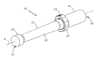
最初に、切削工具10の前後端12,14を通過する長手方向軸線Aを有する切削工具10を示した図1に対して参照がなされる。この切削工具は、外周面18と前端に切削ヘッド20とを有するシャンク16を具えている。切削ヘッド20の具体的な形状が本発明にとって必須ではないことは理解されており、それで切削ヘッドをドリルやリーマーまたは他の工具として形成することができる。シャンクの後端の部分は工具ホルダーに固定するためにある。径方向の振れを調整するための調整リング22は、ねじ部材24によってシャンク16に取り外し可能に固定される。
Reference is first made to FIG. 1 showing a
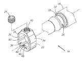
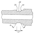
さて、注意が図2から図6に引きつけられる。シャンク16は、円周溝26をこのシャンク16の溝26に取り外し可能に固定される調整リング22と共に有する。円周溝26は、内壁28と2つの側壁30とを有する。内壁28は、形状が円柱状であって径方向外側を向いている。側壁30は、シャンク16の内壁28から外周面18まで外側に発散している。これら2つの側壁30は、シャンクの縦断面においてそれらの間に図4に示すような鋭角αを形成する。
Attention is now drawn to FIGS. The
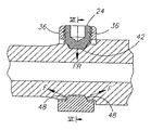
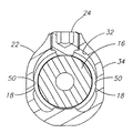
調整リング22は、形状が環状であって逆方向を向く対向端面36の間に延在する内周および外周面32,34を有する。内周面32は、切削工具10のシャンク16が配される中央貫通穴38を画成する。貫通ねじ穴40は、内周および外周面32,34の間に延在する。ねじ部材24が貫通ねじ穴40にねじ込んで取り付けられ、調整リング22の内側に突出する。このねじ部材24は、切削工具10の径方向の振れの調整中に溝26の内壁28に係合するようになっている支承面42を有する。ねじ部材24が貫通ねじ穴40にねじ込まれて取り付けられ、溝26に係合すると、ねじ部材24は支承面42を介して溝26の内壁28に係合する。このねじ部材24は、溝26の側壁30や溝26の他のあらゆる面に係合しない。この実施形態の図に見られるように、調整リング22には単一のこのような貫通穴40のみが与えられ、単一のねじ部材24だけが調整リング22に取り付けられてシャンク16に係合する。
The
調整部材44は、内周面32から調整リング22の内側の貫通ねじ穴40に向けた方向に突出し、この貫通ねじ穴40の正反対に配される。この調整部材44は、貫通ねじ穴40の方に内側を向く内側面46と、この内側面46から離れて延在すると共に相互に離れて分かれる2つの端面48とを有する。内側面46は、ねじ部材24の支承面42に対向する。2つの端面48は、例えば図5で見ることができるように、シャンクの縦断面においてこれらの間に鋭角を形成する。調整リング22がシャンク16の溝26に取り外し可能に固定されて調整部材44が溝26に係合した場合、調整部材44は、端面48を介して溝26の側壁30に係合する。調整部材44は、溝26の内側面46や溝26の他のいかなる面にも係合しない。
The
調整部材44および貫通ねじ穴40は、調整リング22を2等分に分ける。調整リング22には、相互に向き合うと共に相互に正反対に配される2つの支持面50が設けられる。これら支持面50は、内周面32から内側に突出する。一方の支持面50は調整リング22の片側に配されると共に他方の支持面50は調整リング22の他方の片側に配される。支持面50のそれぞれは、溝の最大長さ寸法L2よりも大きな最小長さ寸法L1を有する。
The
初期位置において、切削工具10の径方向の振れを調整する前に、調整リング22は、シャンク16の溝26に大ざっぱに固定され、ねじ部材24の支承面42が溝26の内壁28に滑動可能に係合すると共に調整部材44の端面48が溝26の側壁に滑動可能に係合する。支持面50は、初期位置においてシャンク16の外周面18に係合しないことが好ましい。この初期位置において、調整リング22は、初期位置から、径方向の振れ調整が必要とされる方向に対応した最終的な位置まで、軸線Aを中心に連続的に回転することができる。調整リング22の回転中、ねじ部材24の支承面は溝26の内壁28を滑り、調整部材44の端面48は溝26の側壁を滑動する。
In the initial position, before adjusting the radial runout of the
調整リング22が最終位置に達すると、ねじ部材24がねじ込まれる。ねじ部材24がねじ込まれると、これは貫通ねじ穴40に対して径方向内側へ移動し、溝26に対して純粋に径方向を向く力FRを加え、これによって貫通ねじ穴40を取り囲む調整リング22の領域がシャンク16から径方向外側に離れて移動するようにさせる。ねじ部材24の支承面42のみが溝26に係合してこれが溝26の内壁28にのみ係合するので、ねじ部材24は、溝26に対して純粋に径方向を向く力FRを加える。貫通ねじ穴40を取り囲む調整リング22の領域の径方向外側の移動は、調整部材44がさらに径方向内側に溝26へと移動することをもたらす。さらに、支持面50は、これらがシャンク16の外周面18に係合するまで径方向内側に移動しよう。支持面50のそれぞれは、溝26の何れかの側の溝26に隣接する領域でシャンク16の外周面18に係合しよう。従って、ねじ部材24をねじ込むことにより、支持面50は、これらがシャンク16の外周面18に係合しない第1の位置から、これらがシャンク16の外周面18に係合する第2の位置まで移動可能である。
When the
調整部材44が径方向内側に溝26へと移動すると、これは調整部材44の端面48と溝26の側壁30との係合を介して逆の径方向を向く力Fを溝26に加える。逆の径方向を向く力Fは、側壁30が隣接する調整部材44から離れてさらに押され、これによって調整部材44に隣接する側壁30の間の鋭角αを増大させるので、シャンク16に曲げモーメントを引き起こさせる。シャンク16に対する曲げモーメントの結果として、シャンク16の前端12はこれがあった元の位置から離れて径方向に移動し、これによって必要とされる径方向の振れを調整する。
As the
調整リング22が切削工具10の軸線Aを中心として360°全域を連続的に回転できるので、径方向の振れを任意の必要とされる径方向に修正することができる。
Since the
本発明の調整リングは、最初に円周溝なしで製造した切削工具に対し、形状および寸法がこの調整リングに対応した適当な円周溝をそれらのシャンクに単に形成することによって適用させることができる。 The adjustment ring of the present invention can be applied to a cutting tool originally manufactured without a circumferential groove by simply forming appropriate circumferential grooves in their shanks corresponding in shape and dimensions to the adjustment ring. it can.
本発明の調整リングは、操作が非常に簡単である。調整リング22が必要とされる位置に回転することができるように、ねじ部材24を充分に緩めることが単に必要とされるだけであり、次いで径方向の振れを修正するためにねじ部材をねじ込むことができる。
The adjustment ring of the present invention is very easy to operate. It is only necessary to loosen the
切削工具10の径方向の振れの修正中には、調整リング22のねじ部材24がシャンク16の溝26に対して径方向を向く力FRを単に加えるだけである。多くの従来技術の径方向の振れ修正機構と異なり、本発明のねじ部材24は、シャンク16に対して曲げモーメントを直接もたらさない。多くの従来技術の径方向の振れ修正機構においては、円錐頭部を有するボルト、すなわちねじ部材が用いられ、これはシャンクのそれぞれの溝に逆の径方向を向く力を加えて溝を「広げ」、これによってシャンクに曲げモーメントをもたらす円錐頭部である。それ故、多くの従来技術の径方向の振れ修正機構においては、逆の径方向を向く力を加えるボルト、すなわちねじ部材のその部分が、ねじ部材の回転中にそれを行う。これは、摩擦によって円錐頭部の摩耗をもたらすという点で不利である。
During correction of the radial runout of the
本発明をある程度詳細に記述したけれども、以下に請求した本発明の範囲から逸脱することなく、種々の変更および修正を行うことができることを理解すべきである。 Although the invention has been described in some detail, it should be understood that various changes and modifications can be made without departing from the scope of the invention as claimed below.
Claims (13)
このシャンク(16)の前記溝(26)に取り外し可能に固定される調整リング(22)と
を具えた切削工具(10)であって、前記調整リング(22)は、
この調整リング(22)の内側に突出して前記溝(26)に係合するねじ部材(24)が螺着される貫通ねじ穴(40)と、
前記溝(26)に係合し、前記貫通ねじ穴(40)と正反対に配されて前記調整リング(22)の内側に突出する調整部材(44)と
を具え、前記ねじ部材(24)は前記貫通ねじ穴(40)内を回転可能であって、純粋に径方向を向く力を前記溝(26)に及ぼし、それにより径方向内側への前記調整部材(44)の変位を引き起こし、それにより前記調整部材(44)が逆の径方向を向く力を前記溝(26)に及ぼし、それにより曲げモーメントを前記シャンク(16)に引き起こすことを特徴とする切削工具。 A shank (16) having a circumferential groove (26);
A cutting tool (10) comprising an adjusting ring (22) removably fixed in the groove (26) of the shank (16), wherein the adjusting ring (22)
A through screw hole (40) into which a screw member (24) protruding inside the adjustment ring (22) and engaging with the groove (26) is screwed;
The screw member (24) includes an adjustment member (44) that engages with the groove (26) and is arranged opposite to the through screw hole (40) and protrudes to the inside of the adjustment ring (22). It is rotatable in the through screw hole (40) and exerts a purely radial force on the groove (26), thereby causing the adjustment member (44) to be displaced radially inward, The cutting tool characterized in that the adjusting member (44) exerts a force in the opposite radial direction on the groove (26), thereby causing a bending moment on the shank (16).
前記溝(26)は、径方向外側を向く円柱状の内壁(28)と、この内壁(28)から外側に発散した2つの側壁(30)とを有し、
前記調整部材(44)は、前記端面(48)を介して前記側壁(30)に係合する
ことを特徴とする請求項1に記載の切削工具(10)。 The adjusting member (44) has an inner surface facing the inner (46), and a mutually two end faces wither min while the inside surface (46) or al extending (48),
The groove (26) has a cylindrical inner wall (28) facing radially outward, and two side walls (30) diverging outward from the inner wall (28).
The cutting tool (10) according to claim 1, wherein the adjusting member (44) engages the side wall (30) via the end face (48).
Applications Claiming Priority (3)
| Application Number | Priority Date | Filing Date | Title |
|---|---|---|---|
| IL210165 | 2010-12-22 | ||
| IL210165A IL210165A (en) | 2010-12-22 | 2010-12-22 | Cutting tool |
| PCT/IL2011/000906 WO2012085904A1 (en) | 2010-12-22 | 2011-11-27 | Cutting tool having a shank-mounted adjustment ring |
Publications (3)
| Publication Number | Publication Date |
|---|---|
| JP2014505599A JP2014505599A (en) | 2014-03-06 |
| JP2014505599A5 JP2014505599A5 (en) | 2014-12-04 |
| JP5832550B2 true JP5832550B2 (en) | 2015-12-16 |
Family
ID=44718331
Family Applications (1)
| Application Number | Title | Priority Date | Filing Date |
|---|---|---|---|
| JP2013545631A Active JP5832550B2 (en) | 2010-12-22 | 2011-11-27 | Cutting tool with shank mounting adjustment ring |
Country Status (13)
| Country | Link |
|---|---|
| US (1) | US8556551B2 (en) |
| EP (1) | EP2654995B1 (en) |
| JP (1) | JP5832550B2 (en) |
| KR (1) | KR101620673B1 (en) |
| CN (1) | CN103260802B (en) |
| BR (1) | BR112013012104B1 (en) |
| CA (1) | CA2822356C (en) |
| ES (1) | ES2539380T3 (en) |
| IL (1) | IL210165A (en) |
| PL (1) | PL2654995T3 (en) |
| PT (1) | PT2654995E (en) |
| RU (1) | RU2572945C2 (en) |
| WO (1) | WO2012085904A1 (en) |
Families Citing this family (6)
| Publication number | Priority date | Publication date | Assignee | Title |
|---|---|---|---|---|
| TWM350431U (en) * | 2008-09-03 | 2009-02-11 | Syntec Machinery Co Ltd | Adjustable securely-mounted tool bar of spindle |
| DE202014008275U1 (en) * | 2014-10-16 | 2014-10-27 | KARL SCHÜSSLER GmbH & Co. KG | clamping system |
| EP3338930B1 (en) * | 2016-12-23 | 2020-06-17 | Walter Ag | A ball nose end mill insert, a ball nose end mill tool body and a ball nose end mill |
| US12032351B2 (en) | 2018-03-02 | 2024-07-09 | Big Daishowa Co., Ltd | System for adjusting balance and runout of rotary tool, device for determining the balance and runout, method of adjusting the balance and runout, and tool holder |
| JP7180120B2 (en) | 2018-05-29 | 2022-11-30 | トヨタ自動車株式会社 | tool holder |
| CN110281303B (en) * | 2019-07-23 | 2024-08-13 | 深圳市沃尔核材股份有限公司 | Perforating wheel and perforating equipment |
Family Cites Families (15)
| Publication number | Priority date | Publication date | Assignee | Title |
|---|---|---|---|---|
| CH237045A (en) | 1943-05-26 | 1945-03-31 | Oerlikon Buehrle Ag | Steel holder. |
| SU986622A1 (en) * | 1980-12-24 | 1983-01-07 | Дальневосточный Ордена Трудового Красного Знамени Политехнический Институт Им.В.В.Куйбышева | Boring bar |
| SU1196163A1 (en) * | 1984-09-01 | 1985-12-07 | Предприятие П/Я В-8710 | Chuck for securing a tool |
| US4611960A (en) * | 1985-01-25 | 1986-09-16 | The Jacobs Manufacturing Company | Tool holder |
| FR2586951B1 (en) * | 1985-09-09 | 1994-08-12 | Saint Etienne Fabrique Outilla | BORING APPARATUS |
| SU1315157A1 (en) * | 1985-11-04 | 1987-06-07 | Предприятие П/Я А-7204 | Chuck for securing shank-type cutting tool |
| ATE55716T1 (en) | 1986-03-03 | 1990-09-15 | Dihart Ag | TOOL HOLDER. |
| CZ278297B6 (en) * | 1989-09-12 | 1993-11-17 | Stanislav Fiala | Tool unit, particularly for finishing operations of metal cutting |
| CH681964A5 (en) * | 1990-08-21 | 1993-06-30 | Planetron Ag | |
| JP3258626B2 (en) * | 1997-07-29 | 2002-02-18 | 株式会社エムエスティコーポレーション | Tool holder |
| JP3836606B2 (en) * | 1998-09-02 | 2006-10-25 | ヤマザキマザック株式会社 | Anti-vibration tool holder |
| KR100610548B1 (en) * | 1999-08-30 | 2006-08-09 | 에누티쯔루 가부시키가이샤 | Tool holder and vibration complementing apparatus of the tool holder |
| GB9928466D0 (en) | 1999-12-03 | 2000-02-02 | Cogsdill Nuneaton Limited | Cutting tool |
| JP3704320B2 (en) | 2002-03-18 | 2005-10-12 | 株式会社日研工作所 | Tool holder |
| RU2287406C1 (en) * | 2005-07-13 | 2006-11-20 | Ярославский государственный технический университет | Boring head |
-
2010
- 2010-12-22 IL IL210165A patent/IL210165A/en active IP Right Grant
-
2011
- 2011-10-28 US US13/284,463 patent/US8556551B2/en active Active
- 2011-11-27 JP JP2013545631A patent/JP5832550B2/en active Active
- 2011-11-27 CA CA2822356A patent/CA2822356C/en active Active
- 2011-11-27 RU RU2013134157/02A patent/RU2572945C2/en active
- 2011-11-27 WO PCT/IL2011/000906 patent/WO2012085904A1/en unknown
- 2011-11-27 ES ES11804824.8T patent/ES2539380T3/en active Active
- 2011-11-27 PL PL11804824T patent/PL2654995T3/en unknown
- 2011-11-27 BR BR112013012104-1A patent/BR112013012104B1/en active IP Right Grant
- 2011-11-27 EP EP11804824.8A patent/EP2654995B1/en active Active
- 2011-11-27 CN CN201180062029.7A patent/CN103260802B/en active Active
- 2011-11-27 PT PT118048248T patent/PT2654995E/en unknown
- 2011-11-27 KR KR1020137015475A patent/KR101620673B1/en active IP Right Grant
Also Published As
| Publication number | Publication date |
|---|---|
| ES2539380T3 (en) | 2015-06-30 |
| CN103260802A (en) | 2013-08-21 |
| IL210165A (en) | 2015-01-29 |
| CN103260802B (en) | 2015-12-16 |
| US8556551B2 (en) | 2013-10-15 |
| CA2822356C (en) | 2015-12-15 |
| PT2654995E (en) | 2015-06-30 |
| RU2572945C2 (en) | 2016-01-20 |
| EP2654995A1 (en) | 2013-10-30 |
| IL210165A0 (en) | 2011-03-31 |
| US20120163936A1 (en) | 2012-06-28 |
| RU2013134157A (en) | 2015-01-27 |
| BR112013012104A2 (en) | 2016-09-27 |
| PL2654995T3 (en) | 2015-10-30 |
| WO2012085904A1 (en) | 2012-06-28 |
| EP2654995B1 (en) | 2015-04-08 |
| JP2014505599A (en) | 2014-03-06 |
| BR112013012104B1 (en) | 2020-11-03 |
| KR101620673B1 (en) | 2016-05-12 |
| KR20130132476A (en) | 2013-12-04 |
| CA2822356A1 (en) | 2012-06-28 |
Similar Documents
| Publication | Publication Date | Title |
|---|---|---|
| JP5832550B2 (en) | Cutting tool with shank mounting adjustment ring | |
| US9352405B2 (en) | Metal-cutting tool, in particular reaming tool | |
| JP5612077B2 (en) | Rotary cutting tool | |
| WO2014175114A1 (en) | Cutting blade position adjustment mechanism and cutting edge-replaceable cutting tool | |
| JP6591982B2 (en) | Peripheral cutting tool using stick blade | |
| US11260460B2 (en) | Stop for a drilling, milling or countersinking tool | |
| US20110188954A1 (en) | Boring tool | |
| JP2012187705A (en) | Tool for turn/turn broaching or external milling | |
| US20170028479A1 (en) | Rotatable cutting tool and key therefor | |
| JP2011529802A (en) | Cutting tool with bi-directional adjustment mechanism | |
| JP5372563B2 (en) | Internal grinding tool | |
| JP5378748B2 (en) | Boring tool and boring method | |
| JPH07251306A (en) | Device for correcting alignment error | |
| CN101870010B (en) | Assembly for connecting a tool wheel and a tool holder | |
| JP2010105121A (en) | Collet holder | |
| JP5780188B2 (en) | Clamping mechanism of cutting member and blade part exchangeable cutting tool using the same | |
| US20140161551A1 (en) | Rotary Tool, In Particular Reaming Tool and Adjustment Element For a Rotary Tool | |
| JP2015213968A (en) | Play regulation mechanism for drilling tool | |
| JP2016001032A (en) | Adjustment screw, operating tool, and cutting tool | |
| JP4265372B2 (en) | Bowling bar | |
| WO2009016777A1 (en) | Work machine | |
| JP2019072790A (en) | Tool holder | |
| CA3022283A1 (en) | Holder for a rotary tool comprising with radially and axially movable restriant elements | |
| KR20220071971A (en) | Simultaneous tool holder and rotary cutting tool with radially adjustable insert cartridges | |
| JP5825168B2 (en) | Clamping mechanism of cutting member and blade part exchangeable cutting tool using the same |
Legal Events
| Date | Code | Title | Description |
|---|---|---|---|
| A521 | Request for written amendment filed |
Free format text: JAPANESE INTERMEDIATE CODE: A523 Effective date: 20141009 |
|
| A621 | Written request for application examination |
Free format text: JAPANESE INTERMEDIATE CODE: A621 Effective date: 20141009 |
|
| A131 | Notification of reasons for refusal |
Free format text: JAPANESE INTERMEDIATE CODE: A131 Effective date: 20150707 |
|
| A521 | Request for written amendment filed |
Free format text: JAPANESE INTERMEDIATE CODE: A523 Effective date: 20150722 |
|
| TRDD | Decision of grant or rejection written | ||
| A01 | Written decision to grant a patent or to grant a registration (utility model) |
Free format text: JAPANESE INTERMEDIATE CODE: A01 Effective date: 20150929 |
|
| A61 | First payment of annual fees (during grant procedure) |
Free format text: JAPANESE INTERMEDIATE CODE: A61 Effective date: 20151027 |
|
| R150 | Certificate of patent or registration of utility model |
Ref document number: 5832550 Country of ref document: JP Free format text: JAPANESE INTERMEDIATE CODE: R150 |
|
| R250 | Receipt of annual fees |
Free format text: JAPANESE INTERMEDIATE CODE: R250 |
|
| R250 | Receipt of annual fees |
Free format text: JAPANESE INTERMEDIATE CODE: R250 |
|
| R250 | Receipt of annual fees |
Free format text: JAPANESE INTERMEDIATE CODE: R250 |
|
| R250 | Receipt of annual fees |
Free format text: JAPANESE INTERMEDIATE CODE: R250 |
|
| R250 | Receipt of annual fees |
Free format text: JAPANESE INTERMEDIATE CODE: R250 |
|
| R250 | Receipt of annual fees |
Free format text: JAPANESE INTERMEDIATE CODE: R250 |
