JP5831258B2 - Braking / driving force control device for vehicle - Google Patents
Braking / driving force control device for vehicle Download PDFInfo
- Publication number
- JP5831258B2 JP5831258B2 JP2012016143A JP2012016143A JP5831258B2 JP 5831258 B2 JP5831258 B2 JP 5831258B2 JP 2012016143 A JP2012016143 A JP 2012016143A JP 2012016143 A JP2012016143 A JP 2012016143A JP 5831258 B2 JP5831258 B2 JP 5831258B2
- Authority
- JP
- Japan
- Prior art keywords
- wheel
- braking
- driving force
- speed
- vehicle
- Prior art date
- Legal status (The legal status is an assumption and is not a legal conclusion. Google has not performed a legal analysis and makes no representation as to the accuracy of the status listed.)
- Active
Links
Images


Classifications
-
- Y—GENERAL TAGGING OF NEW TECHNOLOGICAL DEVELOPMENTS; GENERAL TAGGING OF CROSS-SECTIONAL TECHNOLOGIES SPANNING OVER SEVERAL SECTIONS OF THE IPC; TECHNICAL SUBJECTS COVERED BY FORMER USPC CROSS-REFERENCE ART COLLECTIONS [XRACs] AND DIGESTS
- Y02—TECHNOLOGIES OR APPLICATIONS FOR MITIGATION OR ADAPTATION AGAINST CLIMATE CHANGE
- Y02T—CLIMATE CHANGE MITIGATION TECHNOLOGIES RELATED TO TRANSPORTATION
- Y02T10/00—Road transport of goods or passengers
- Y02T10/60—Other road transportation technologies with climate change mitigation effect
- Y02T10/72—Electric energy management in electromobility
Description
本発明は、車両の車輪に発生させる制駆動力を制御する車両用制駆動力制御装置に関し、特に、車両の各輪に発生させる制駆動力を独立して制御する車両用制駆動力制御装置に関する。 The present invention relates to a vehicle braking / driving force control device that controls braking / driving force generated on wheels of a vehicle, and more particularly to a vehicle braking / driving force control device that independently controls braking / driving force generated on each wheel of the vehicle. About.
近年、車輪のホイール内部もしくはその近傍に電動機(電気モータ)等の駆動源を配置し、この駆動源により車輪を独立的に駆動又は制動する車両が開発されている。このような車両としては、所謂、インホイールモータ方式の車両を挙げることができる。このインホイールモータ方式の車両においては、各輪(駆動輪)ごとに設けた電動機を個別に回転制御する、すなわち、各電動機を個別に力行制御又は回生制御することにより、各駆動輪に付与する駆動トルク又は制動トルクを個別に制御することができる。 In recent years, a vehicle has been developed in which a drive source such as an electric motor (electric motor) is arranged in or near the wheel of the wheel, and the wheel is independently driven or braked by this drive source. An example of such a vehicle is a so-called in-wheel motor vehicle. In this in-wheel motor type vehicle, the motor provided for each wheel (drive wheel) is individually controlled for rotation, that is, each motor is individually controlled for power running or regenerative control to be applied to each drive wheel. The driving torque or braking torque can be individually controlled.
そして、このように各駆動輪に付与する駆動トルク又は制動トルクを個別に制御できる車両に対しても、例えば、下記特許文献1に示されるアンチロック制御装置を適用することができる。この従来のアンチロック制御装置では、原則、車輪のそれぞれに取り付けられた車輪速センサからの信号を用いて演算された全車輪速度のうちの最高車輪速度をもとに車体の推定速度を求めるようになっており、最高車輪速度を除く他の複数の車輪速度の中で最大と最小の速度差が所定の第1閾値内であり、かつ、最高車輪速度と、前記他の複数の車輪速度の中での最大車輪速度との差が所定の第2閾値以上である状態が所定の第1期間を超えて継続していることを検出した時に、最高車輪速度が得られた車輪の速度を推定車体速度の算出に使用することを禁止するようになっている。 For example, an antilock control device disclosed in Patent Document 1 described below can be applied to a vehicle that can individually control the driving torque or braking torque applied to each driving wheel. In this conventional anti-lock control device, in principle, the estimated speed of the vehicle body is obtained based on the maximum wheel speed among all the wheel speeds calculated using the signals from the wheel speed sensors attached to the wheels. The difference between the maximum and minimum speeds among the plurality of other wheel speeds excluding the maximum wheel speed is within a predetermined first threshold, and the maximum wheel speed and the other wheel speeds When it is detected that the state in which the difference from the maximum wheel speed in the vehicle is greater than or equal to a predetermined second threshold continues beyond the predetermined first period, the wheel speed at which the maximum wheel speed is obtained is estimated. It is prohibited to use it for calculating the vehicle speed.
又、上述した車両に対しては、例えば、下記特許文献2に示される車両のスリップ制御装置も適用することができる。この従来の車両のスリップ制御装置では、運転者によって車両加速の指示がされた時に駆動輪のスリップ率が所定値近傍におさまるように車輪駆動出力及び駆動輪制動力の少なくとも一方を調整する加速スリップ制御手段と、運転者による車両制動の指示がされた時に車輪のスリップ率が所定値近傍におさまるように車輪制動力を調整するアンチスキッド制御手段とを有しており、運転者によって車両加速及び車両制動の指示が同時にされていると判定されると、駆動輪制動力制御部を用いることを禁止するようになっている。 Further, for example, a vehicle slip control device disclosed in Patent Document 2 below can be applied to the above-described vehicle. In this conventional vehicle slip control device, an acceleration slip that adjusts at least one of the wheel drive output and the drive wheel braking force so that the slip ratio of the drive wheel is kept in the vicinity of a predetermined value when the driver gives an instruction to accelerate the vehicle. Control means, and anti-skid control means for adjusting the wheel braking force so that the slip ratio of the wheel is close to a predetermined value when the driver gives an instruction to brake the vehicle. When it is determined that the vehicle braking instruction is given at the same time, the use of the driving wheel braking force control unit is prohibited.
ところで、上述したインホイールモータ方式の車両のように、各車輪の駆動力及び制動力を独立して制御可能な車両においては、例えば、車両の走行環境(路面状態等)に応じて、或いは、良好な操安性を確保するために、駆動力を発生して駆動状態にある車輪と制動力を発生して制動状態にある車輪とが同時に存在する場合がある。この場合、上記特許文献1に記載された従来のアンチロック制御装置を上述した車両に適用すると、例えば、最大車輪速度として駆動状態にある車輪の車輪速度が推定車体速度の算出に使用される場合があり、この場合には、推定車体速度が実際の車体速度よりも大きくなるために既に制動状態にある車輪のスリップ率が相対的に大きくなって無用なアンチロック制御(ABS制御)が介入する可能性がある。 By the way, in the vehicle in which the driving force and the braking force of each wheel can be controlled independently, such as the in-wheel motor type vehicle described above, for example, according to the traveling environment (road surface condition, etc.) of the vehicle, or In order to ensure good maneuverability, there are cases where a wheel in a driving state by generating a driving force and a wheel in a braking state by generating a braking force exist simultaneously. In this case, when the conventional antilock control device described in Patent Document 1 is applied to the above-described vehicle, for example, the wheel speed of the wheel in the driving state is used as the maximum wheel speed to calculate the estimated vehicle body speed. In this case, since the estimated vehicle speed becomes larger than the actual vehicle speed, the slip ratio of the wheel already in the braking state becomes relatively large, and unnecessary antilock control (ABS control) intervenes. there is a possibility.
本発明は、上記した問題に対処するためになされたものであり、その目的の一つは、精度よく車体速度を演算し車輪に発生しているスリップ状態を制御する車両用制駆動力制御装置を提供することにある。 The present invention has been made in order to cope with the above-described problems, and one of its purposes is a vehicle braking / driving force control device for accurately calculating a vehicle body speed and controlling a slip state generated in a wheel. Is to provide.
係る目的を達成するための本発明による車両用制駆動力制御装置は、制駆動力発生機構と、車輪速度検出手段と、車体速度推定手段と、減速スリップ状態判定手段又は加速スリップ状態判定手段と、制駆動力制御手段と、を備えている。
A vehicle braking / driving force control device according to the present invention for achieving such an object includes a braking / driving force generation mechanism, wheel speed detection means, vehicle body speed estimation means, deceleration slip condition determination means or acceleration slip condition determination means. And braking / driving force control means .
前記制駆動力発生機構は、車両の各車輪に対してそれぞれ独立して付与される駆動力及び制動力を発生させる。前記制駆動力発生機構として、具体的には、車両の各車輪に直接的又は間接的に設けられて力行制御によって電磁的な駆動力を発生するとともに回生制御によって電磁的な制動力を発生する電動機(インホイールモータ)や、車両の各輪に設けられて回転する車輪に対して摩擦による機械的な制動力を発生するディスクブレーキやドラムブレーキ等を挙げることができる。
The braking / driving force generating mechanism generates a driving force and a braking force that are independently applied to each wheel of the vehicle. Specifically, the braking / driving force generation mechanism is provided directly or indirectly on each wheel of the vehicle to generate electromagnetic driving force by power running control and to generate electromagnetic braking force by regenerative control. Examples thereof include an electric motor (in-wheel motor), a disc brake, a drum brake, and the like that generate a mechanical braking force due to friction with respect to a wheel provided on each wheel of the vehicle and rotating.
前記車輪速度検出手段は、前記車輪の車輪速度をそれぞれ検出する。
前記車体速度推定手段は、前記車両の車体速度を推定する。
The wheel speed detection means for detecting a wheel speed of the wheel, respectively.
The vehicle body speed estimation means estimates a vehicle body speed of the vehicle.
前記減速スリップ状態判定手段は、前記車輪速度検出手段によって検出された車輪速度と前記車体速度推定手段によって推定された車体速度とに基づいて各車輪について減速スリップ状態(制動(減速)に伴って車輪に発生するスリップ状態)が生じているか否かを判定する。The deceleration slip state determination means includes a deceleration slip state for each wheel (according to braking (deceleration)) based on the wheel speed detected by the wheel speed detection means and the vehicle body speed estimated by the vehicle body speed estimation means. It is determined whether or not there is a slip state that occurs.
前記加速スリップ状態判定手段は、前記車輪速度検出手段によって検出された車輪速度と前記車体速度推定手段によって推定された車体速度とに基づいて各車輪について加速スリップ状態(駆動(加速)に伴って車輪に発生するスリップ状態)が生じているか否かを判定する。The accelerating slip state determination means includes an acceleration slip state for each wheel based on the wheel speed detected by the wheel speed detection means and the vehicle body speed estimated by the vehicle body speed estimation means. It is determined whether or not there is a slip state that occurs.
前記制駆動力制御手段は、何れかの車輪に前記減速スリップ状態が生じていると判定された場合、前記減速スリップ状態が生じていると判定された車輪に付与される駆動力又は制動力を、前記減速スリップ状態が生じない駆動力又は制動力に制御する。具体的には、前記駆動力制御手段は、例えば、減速スリップ状態が生じている車輪を対象とするアンチスキッド制御を実行する。When the braking / driving force control means determines that the deceleration slip state is occurring in any of the wheels, the braking / driving force control means applies a driving force or a braking force applied to the wheel determined to be causing the deceleration slip state. The driving force or the braking force is controlled so that the deceleration slip state does not occur. Specifically, the driving force control means executes anti-skid control for wheels that are in a deceleration slip state, for example.
一方、前記制駆動力制御手段は、何れかの車輪に加速スリップ状態が生じていると判定された場合、前記加速スリップ状態が生じていると判定された車輪に付与される駆動力又は制動力を、前記加速スリップ状態が生じない駆動力又は制動力に制御する。具体的には、前記駆動力制御手段は、例えば、加速スリップ状態が生じている車輪を対象とするトラクション制御を実行する。On the other hand, the braking / driving force control means, when it is determined that an acceleration slip state has occurred in any of the wheels, the driving force or braking force applied to the wheel that has been determined that the acceleration slip state has occurred. Is controlled to a driving force or a braking force that does not cause the acceleration slip state. Specifically, the driving force control means executes traction control for wheels that are in an accelerated slip state, for example.
そして、本発明による車両用制駆動力制御装置の特徴の一つは、前記車体速度推定手段が、前記減速スリップ状態判定手段による判定に用いる車体速度を、前記車輪速度検出手段によって検出された車輪速度のうち、前記駆動力が付与されている車輪の車輪速度を用いずに前記制動力が付与されている車輪の車輪速度のみを用いて推定する、ことにある。
One feature of the vehicle braking / driving force control device according to the present invention is that the vehicle body speed estimation means detects the vehicle body speed used for the determination by the deceleration slip state determination means by the wheel speed detection means. The speed is estimated using only the wheel speed of the wheel to which the braking force is applied without using the wheel speed of the wheel to which the driving force is applied.
これによれば、例えば、アンチスキッド制御が適正な車輪について実行され、その結果、無用なアンチスキッド制御の実行を防止することができる。According to this, for example, the anti-skid control is executed for an appropriate wheel, and as a result, unnecessary anti-skid control can be prevented from being executed.
更に、本発明による車両用制駆動力制御装置の特徴のもう一つは、前記車体速度推定手段が、前記加速スリップ状態判定手段による判定に用いる車体速度を、前記車輪速度検出手段によって検出された車輪速度のうち、前記制動力が付与されている車輪の車輪速度を用いずに前記駆動力が付与されている車輪の車輪速度のみを用いて推定する、ことにある。Furthermore, another feature of the vehicle braking / driving force control device according to the present invention is that the vehicle body speed estimation means detects the vehicle body speed used for the determination by the acceleration slip state determination means by the wheel speed detection means. In the wheel speed, the estimation is performed using only the wheel speed of the wheel to which the driving force is applied without using the wheel speed of the wheel to which the braking force is applied.
これによれば、例えば、トラクション制御が適正な車輪について実行され、その結果、無用なトラクション制御の実行を防止することができる。According to this, for example, traction control is executed for an appropriate wheel, and as a result, unnecessary traction control can be prevented from being executed.
更に、前記車体速度推定手段は、所定の閾値に基づいて前記駆動力が付与されている車輪、又は、前記制動力が付与されている車輪を判別してもよい。この場合において、前記車体速度推定手段は、前記車両が走行する道路の路面状態に応じて前記所定の閾値を変更してもよい。Furthermore, the vehicle body speed estimation means may determine a wheel to which the driving force is applied or a wheel to which the braking force is applied based on a predetermined threshold. In this case, the vehicle body speed estimation means may change the predetermined threshold according to a road surface state of a road on which the vehicle travels.
これらによれば、例えば、所定の閾値を車輪に加速スリップ又は車輪に減速スリップが発生しない程度の値に設定することにより、駆動力を発生している車輪であっても、加速スリップするような駆動状態にある車輪とせずに制動状態にある車輪とみなして、この車輪の車輪速度を減速スリップ状態を制御するときの車体速度の推定に用いることができる。或いは、制動力を発生している車輪であっても、減速スリップするような制動状態にある車輪とせずに駆動状態にある車輪とみなして、この車体速度の推定に用いることができる。これにより、推定される車体速度をより実際の車体速度に近づけることができる、言い換えれば、車体速度をより精度よく推定することができて、より適切にスリップ状態にある車輪の制御を実行することができる。 According to these, for example, by setting a predetermined threshold value to a value that does not cause acceleration slip or deceleration slip on the wheel, even if the wheel is generating driving force, the slip is accelerated. The wheel speed of this wheel can be used for estimation of the vehicle body speed when controlling the deceleration slip state, considering that the wheel is in a braking state and not the wheel in the driving state. Or even if it is a wheel which is generating braking force, it can be considered as a wheel in a driving state instead of a wheel in a braking state which decelerates and slips, and can be used for estimation of this body speed. As a result, the estimated vehicle speed can be made closer to the actual vehicle speed, in other words, the vehicle speed can be estimated more accurately, and the control of the wheel in the slip state can be executed more appropriately. Can do.
以下、本発明の実施形態を、図面を用いて詳細に説明する。図1は、本実施形態に係る車両用制駆動力制御装置が搭載される車両Veの構成を概略的に示している。 Hereinafter, embodiments of the present invention will be described in detail with reference to the drawings. FIG. 1 schematically shows the configuration of a vehicle Ve on which the vehicle braking / driving force control device according to this embodiment is mounted.
車両Veは、左右前輪11,12及び左右後輪13,14を備えている。そして、左右前輪11,12のホイール内部には電動機15,16が組み込まれ、左右後輪13,14のホイール内部には電動機17,18が組み込まれており、電動機15〜18は、それぞれ、左右前輪11,12及び左右後輪13,14に図示省略の動力伝達系(例えば、減速機)を介して動力伝達可能に連結されている。すなわち、電動機15〜18は、所謂、インホイールモータ15〜18であり、左右前輪11,12及び左右後輪13,14とともに車両Veのバネ下に配置されている。そして、各インホイールモータ15〜18の回転をそれぞれ独立して制御することにより、左右前輪11,12及び左右後輪13,14に発生させる駆動力及び制動力をそれぞれ独立して制御することができるようになっている。
The vehicle Ve includes left and right
これらの各インホイールモータ15〜18は、例えば、交流同期モータにより構成されている。そして、各インホイールモータ15〜18には、インバータ19を介して、バッテリやキャパシタ等の蓄電装置20の直流電力が交流電力に変換され、その交流電力が供給されるようになっている。これにより、各インホイールモータ15〜18は、駆動制御(すなわち、力行制御)されて、左右前輪11,12及び左右後輪13,14に対して電磁的な駆動力としてのモータ駆動トルクを付与する。
Each of these in-wheel motors 15-18 is comprised by the alternating current synchronous motor, for example. And each in-wheel motor 15-18 converts the direct current power of the
又、各インホイールモータ15〜18は、左右前輪11,12及び左右後輪13,14の回転エネルギーを利用して回生制御することができる。これにより、各インホイールモータ15〜18の回生・発電時には、左右前輪11,12及び左右後輪13,14の回転(運動)エネルギーが各インホイールモータ15〜18によって電気エネルギーに変換され、その際に生じる電力(回生電力)がインバータ19を介して蓄電装置20に蓄電される。このとき、各インホイールモータ15〜18は、左右前輪11,12及び左右後輪13,14に対して回生発電に伴う電磁的な制動力としてのモータ制動トルクを付与する。
The in-
又、各輪11〜14と、これらに対応する各インホイールモータ15〜18との間には、それぞれ、摩擦ブレーキ機構21,22,23,24が設けられている。各摩擦ブレーキ機構21〜24は、例えば、ディスクブレーキやドラムブレーキ等の公知の制動装置であり、左右前輪11,12及び左右後輪13,14に対して摩擦による機械的な制動力としての摩擦制動力Fmを付与する。そして、これらの摩擦ブレーキ機構21〜24は、ブレーキペダルBの踏み込み操作に起因して図示を省略するマスタシリンダから圧送される油圧(液圧)により、各輪11〜14に制動力を生じさせるブレーキキャリパのピストンやブレーキシュー(ともに図示省略)等を作動させるブレーキアクチュエータ25に接続されている。
In addition,
上記インバータ19及びブレーキアクチュエータ25は、各インホイールモータ15〜18の回転状態(より詳しくは、力行状態又は回生状態)、及び、摩擦ブレーキ機構21〜24の動作状態(より詳しくは、制動状態又は制動解除状態)を制御する電子制御ユニット26にそれぞれ接続されている。従って、各インホイールモータ15〜18、インバータ19及び蓄電装置20と、摩擦ブレーキ機構21〜24及びブレーキアクチュエータ25は本発明の制駆動力発生機構を構成する。
The
電子制御ユニット26は、CPU、ROM、RAM等からなるマイクロコンピュータを主要構成部品とするものであり、後述するプログラムを含む各種プログラムを実行することによって、各インホイールモータ15〜18及び摩擦ブレーキ機構21〜24を制御して車輪に発生しているスリップ状態を制御するものである。従って、電子制御ユニット26は本発明のスリップ制御手段を構成する。このため、電子制御ユニット26には、運転者によるアクセルペダルAの踏み込みストローク量Sを検出するアクセルセンサ27、運転者によるブレーキペダルBの踏み込み力Pを検出するブレーキセンサ28、各輪11〜14の車輪速度Vwi(i=fl,fr,rl,rr)を検出する車輪速度検出手段としての車輪速度センサ29i(i=fl,fr,rl,rr)を含む各種センサからの信号及びインバータ19からの信号が入力されるようになっている。
The
このように、電子制御ユニット26に対して上記各センサ27〜29i及びインバータ19が接続されて各信号が入力されることにより、電子制御ユニット26は車両Veの走行状態を把握してインホイールモータ15〜18及び摩擦ブレーキ機構21〜24の作動を制御することができる。具体的に説明すると、電子制御ユニット26は、アクセルセンサ27及び車輪速度センサ29i(i=fl,fr,rl,rr)から入力される信号に基づいて、運転者によるアクセルペダルAの操作(以下、加速操作と称呼する。)に伴うストローク量Sに応じた走行用駆動力Fd、すなわち、車両Veを加速させて走行するために各インホイールモータ15〜18が発生すべきモータ駆動トルクを演算することができる。又、電子制御ユニット26は、ブレーキセンサ28及び車輪速度センサ29i(i=fl,fr,rl,rr)から入力される信号に基づいて、運転者によるブレーキペダルBの操作(以下、この操作を減速操作と称呼する。)に伴う踏み込み力Pに応じた走行用駆動力Fb、すなわち、車両Veを減速させるために各インホイールモータ15〜18が発生すべきモータ制動トルク及び摩擦ブレーキ機構21〜24が協調して発生すべき摩擦制動力Fmを演算することができる。
As described above, when the
そして、電子制御ユニット26は、インバータ19から入力される信号、具体的には、加速操作に応じた力行制御時(駆動力発生時)に各インホイールモータ15〜18に供給される電力量や電流値を表す信号や、減速操作に応じた回生制御時(制動力発生時)に各インホイールモータ15〜18から回生される電力量や電流値を表す信号に基づいて、走行用駆動力Fd(駆動力)又は走行用駆動力Fb(制動力)に対応するモータ駆動トルク又はモータ制動トルクを各インホイールモータ15〜18に発生させる。これにより、電子制御ユニット26は、インバータ19を介して各インホイールモータ15〜18の回転をそれぞれ力行制御又は回生制御する信号やブレーキアクチュエータ25を介して各摩擦ブレーキ機構21〜24の動作(制動動作又は制動解除動作)をそれぞれ制御する信号を出力することができる。従って、電子制御ユニット26は、少なくとも、アクセルセンサ27及びブレーキセンサ28から入力される各信号に基づいて車両Veを走行させるための走行用駆動力Fd,Fbを求め、その走行用駆動力Fd,Fbを発生させるように力行・回生制御によって各インホイールモータ15〜18を作動させてモータトルクを発生させるとともに、ブレーキアクチュエータ25を介して摩擦ブレーキ機構21〜24を作動させて摩擦制動力Fmを発生させて、車両Veの走行状態を制御することができる。
And the
次に、各インホイールモータ15〜18及び各摩擦ブレーキ機構21〜24を協調させて、電子制御ユニット26による車輪に発生しているスリップ状態の制御を説明する。具体的には、例えば、加速操作時に各輪11〜14のうちのいずれかに発生するスリップ(以下、この加速操作時に発生するスリップを加速スリップと称呼する。)に対応して各インホイールモータ15〜18による走行用駆動力Fd及び摩擦ブレーキ機構21〜24による摩擦制動力Fmを協調させるトラクション制御(以下、TRC制御と称呼する。)と、減速操作時に各輪11〜14のうちのいずれかに発生するスリップ(以下、この減速操作時に発生するスリップを減速スリップと称呼する。)に対応して各インホイールモータ15〜18による走行用駆動力Fb及び摩擦ブレーキ機構21〜24による摩擦制動力Fmを協調させるアンチスキッド制御(以下、ABS制御と称呼する。)とを詳細に説明する。
Next, the control of the slip state generated on the wheels by the
電子制御ユニット26(より詳しくは、CPU)は、TRC制御及びABS制御を実施するにあたり、図2に示す制駆動力制御プログラムを所定の短い時間間隔により繰り返し実行する。具体的に、電子制御ユニット26は、制駆動力制御プログラムをステップS10にて実行を開始し、続くステップS11にて左右前輪11,12及び左右後輪13,14における制駆動力を取得する。すなわち、電子制御ユニット26は、上述したように運転者による加速操作又は減速操作に応じて決定される各インホイールモータ15〜18による走行用駆動力Fd,Fb及び各摩擦ブレーキ機構21〜24による摩擦制動力Fmに基づき、左右前輪11,12がそれぞれ発生する制駆動力Ffl,制駆動力Ffr及び左右後輪13,14がそれぞれ発生する制駆動力Frl,制駆動力Frrを取得する。このように、電子制御ユニット26は、左右前輪11,12及び左右後輪13,14がそれぞれ発生している制駆動力Fi(i=fl,fr,rl,rr)を取得すると、ステップS12に進む。
The electronic control unit 26 (more specifically, the CPU) repeatedly executes the braking / driving force control program shown in FIG. 2 at predetermined short time intervals when performing the TRC control and the ABS control. Specifically, the
ステップS12においては、電子制御ユニット26は、車輪速度センサ29i(i=fl,fr,rl,rr)から各車輪11〜14の車輪速度Vwi(i=fl,fr,rl,rr)を取得する。そして、電子制御ユニット26は、前記ステップS11にて各車輪11〜14の制駆動力Fi(i=fl,fr,rl,rr)を取得するとともに、前記ステップS12にて各車輪11〜14の車輪速度Vwi(i=fl,fr,rl,rr)を取得すると、ステップS13にてTRC制御ルーチンを実行し、又、ステップS14にてABS制御ルーチンを実行する。以下、TRC制御ルーチン及びABS制御ルーチンを詳細に説明する。尚、本実施形態においては、制駆動力制御プログラムに従ってTRC制御ルーチンの実行後にABS制御ルーチンを実行するように実施するが、これらルーチンの実行順序については何ら限定されるものではなく、ABS制御ルーチンの実行後にTRC制御ルーチンを実行可能であることは言うまでもない。
In step S12, the
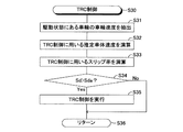
電子制御ユニット26は、ステップS13にてTRC制御ルーチンを実行する。TRC制御ルーチンは、図3に示すように、その実行がステップS30にて開始され、続くステップS31において、電子制御ユニット26は、左右前輪11,12及び左右後輪13,14のうち、現在、駆動状態にある車輪を特定し、この特定した車輪の車輪速度を選択的に抽出する。具体的に、電子制御ユニット26は、まず、前記ステップS11にて取得した各車輪11〜14の制駆動力Fi(i=fl,fr,rl,rr)のうち、現在、運転者による加速操作に応じて各インホイールモータ15〜18が走行用駆動力Fdに対応するモータ駆動トルクを発生している、すなわち、駆動力を発生していて駆動状態にある車輪を特定する。そして、電子制御ユニット26は、各車輪11〜14のうち、駆動状態にある車輪を特定すると、前記ステップS12にて取得した各車輪11〜14の車輪速度Vwi(i=fl,fr,rl,rr)のうちから、前記特定した車輪に対応する車輪速度を選択的に抽出する。尚、以下の説明においては、このように駆動状態にある車輪の車輪速度として選択的に抽出される車輪速度をVdsi(i=fl,fr,rl,rrのうちのいずれか)とする。
The
このように車輪速度Vdsi(i=fl,fr,rl,rrのうちのいずれか)を抽出すると、電子制御ユニット26は、続くステップS32において、加速スリップ対応して各インホイールモータ15〜18による走行用駆動力Fd及び摩擦ブレーキ機構21〜24による摩擦制動力Fmを協調させるTRC制御に用いる推定車体速度VBdを推定演算する。ここで、推定車体速度VBdの推定演算については、従来から広く採用されている周知の演算方法を用いることができるため、以下に具体例として簡単に説明しておく。
When the wheel speed Vdsi (any one of i = fl, fr, rl, and rr) is extracted in this way, the
推定車体速度VBdの推定演算については、例えば、前記ステップS31にて抽出した駆動状態にある車輪の車輪速度Vdsi(i=fl,fr,rl,rrのうちのいずれか)のうち、電子制御ユニット26は、運転者による加速操作に従って走行している車両Veの実際の車体速度に最も近いと考えられる値をまずは推定車体速度VBdwとして選択する。次に、電子制御ユニット26は、前回推定演算した車体推定速度VBdfに対して、推定車体速度の増加率を抑制するための正の定数α1を減じた推定車体速度VBdn1及び推定車体速度の低下率を抑制するための正の定数α2を加えた推定車体速度VBdn2を演算する。そして、電子制御ユニット26は、選択した推定車体速度VBdw、演算した推定車体速度VBdn1及び演算した推定車体速度VBdn2のうちの中間の値を今回の推定車体速度VBdとして推定(決定)する。このように、駆動状態にある車輪の車輪速度Vdsi(i=fl,fr,rl,rrのうちのいずれか)を用いてTRC制御に用いる推定車体速度VBdを推定演算すると、電子制御ユニット26はステップS33に進む。
Regarding the estimation calculation of the estimated vehicle body speed VBd, for example, among the wheel speeds Vdsi (any one of i = fl, fr, rl, rr) of the wheels in the driving state extracted in step S31, the
ステップS33においては、電子制御ユニット26は、各輪11〜14について、前記ステップS32にて推定演算した推定車体速度VBdと各車輪速度Vwi(i=fl,fr,rl,rr)との偏差を用いて表されるTRC制御におけるスリップ率Sdi(i=fl,fr,rl,rr)を演算する。尚、スリップ率Sdi(i=fl,fr,rl,rr)の演算についても、従来から広く採用されている周知の演算方法を用いることができるため、以下に簡単に説明しておく。
In step S33, the
スリップ率Sdi(i=fl,fr,rl,rr)については、電子制御ユニット26は、前記ステップS32にて推定演算した推定車体速度VBdから各車輪速度Vwi(i=fl,fr,rl,rr)をそれぞれ減じる。そして、電子制御ユニット26は、この減じて演算した値を推定車体速度VBdで除することによって、各車輪11〜14のTRC制御におけるスリップ率Sdi(i=fl,fr,rl,rr)を推定して演算する。このように、TRC制御における各車輪11〜14のスリップ率Sdi(i=fl,fr,rl,rr)を演算すると、電子制御ユニット26はステップS34に進む。尚、以下の説明においては、理解を容易とするために、TRC制御における各車輪11〜14のスリップ率Sdi(i=fl,fr,rl,rr)を単に車輪のスリップ率Sdとも称呼する。
Regarding the slip ratio Sdi (i = fl, fr, rl, rr), the
ステップS34においては、電子制御ユニット26は、TRC制御の開始を判定するために設定される目標スリップ率Sdaと前記ステップS33にて推定演算した車輪のスリップ率Sdとを比較し、車輪のスリップ率Sdが目標スリップ率Sdaよりも大きいか否か、言い換えれば、TRC制御を開始するか否かかを判定する。すなわち、電子制御ユニット26は、目標スリップ率Sdaに比して車輪のスリップ率Sdが大きければ、「Yes」と判定してステップS35に進み、周知のTRC制御を実行する。一方、車輪のスリップ率Sdが目標スリップ率Sda以下であれば、電子制御ユニット26は「No」と判定してステップS36に進んでTRC制御ルーチンの実行を終了し、制駆動力制御プログラムのステップS13に戻る。
In step S34, the
ステップS35においては、電子制御ユニット26は、従来から広く採用されている周知のTRC制御に従って、駆動状態にある車輪に設けられているインホイールモータ(インホイールモータ15〜18のうちのいずれか)が発生するモータ駆動トルク(又はモータ制動トルク)及び摩擦ブレーキ機構(摩擦ブレーキ機構21〜24のうちのいずれか)を制御する。すなわち、電子制御ユニット26は、例えば、TRC制御の対象となる車輪のスリップ率Sdが目標スリップ率Sdaよりも小さくなるように、走行用駆動力Fdすなわちインホイールモータが発生するモータ駆動トルクを制御する。このとき、電子制御ユニット26は、例えば、インバータ19を介してインホイールモータに供給する電力を制御して(低下させて)、インホイールモータが発生するモータ駆動トルクを制御(低減)する。或いは、電子制御ユニット26は、ブレーキアクチュエータ25を介して対応する摩擦ブレーキ機構を作動させて所定の大きさの摩擦制動力Fmを発生させて、車輪の走行用駆動力Fdを制御する(低減させる)。そして、電子制御ユニット26は、周知のTRC制御を実行すると、ステップS36に進んでTRC制御ルーチンの実行を終了し、制駆動力制御プログラムのステップS13に戻る。
In step S35, the
TRC制御ルーチンを実行した電子制御ユニット26は、制駆動力制御プログラムのステップS13に戻ると、続いて、ステップS14に進んでABS制御ルーチンを実行する。
After returning to step S13 of the braking / driving force control program, the
ABS制御ルーチンは、図4に示すように、その実行がステップS50にて開始される。そして、電子制御ユニット26は、続くステップS51にて、左右前輪11,12及び左右後輪13,14のうち、現在、制動状態にある車輪を特定し、この特定した車輪の車輪速度を選択的に抽出する。この車輪速度の選択的な抽出においても、上述したTRC制御ルーチンにおける前記ステップS31と同様に、電子制御ユニット26は、まず、前記ステップ11にて取得した各車輪11〜14の制駆動力Fi(i=fl,fr,rl,rr)のうち、現在、運転者による減速操作に応じて各インホイールモータ15〜18が走行用駆動力Fbに対応するモータ制動トルクを発生している、及び、ブレーキアクチュエータ25によって摩擦ブレーキ機構21〜24が摩擦制動力Fmを発生している、すなわち、制動力を発生していて制動状態にある車輪を特定する。そして、電子制御ユニット26は、各車輪11〜14のうち、制動状態にある車輪を特定すると、前記ステップS12にて取得した各車輪11〜14の車輪速度Vwi(i=fl,fr,rl,rr)のうちから、前記特定した車輪に対応する車輪速度を選択的に抽出する。尚、以下の説明においては、このように制動状態にある車輪の車輪速度として選択的に抽出される車輪速度をVbsi(i=fl,fr,rl,rrのうちのいずれか)とする。
As shown in FIG. 4, the ABS control routine is started in step S50. Then, in the following step S51, the
このように車輪速度Vbsi(i=fl,fr,rl,rrのうちのいずれか)を抽出すると、電子制御ユニット26は、続くステップS52において、減速スリップ対応して各インホイールモータ15〜18による走行用駆動力Fb及び摩擦ブレーキ機構21〜24による摩擦制動力Fmを協調させるABS制御に用いる推定車体速度VBbを推定演算する。すなわち、電子制御ユニット26は、上述したTRC制御ルーチンにおける推定車体速度VBdの推定演算と同様にして、例えば、前記ステップS51にて抽出した制動状態にある車輪の車輪速度Vbsi(i=fl,fr,rl,rrのうちのいずれか)のうち、運転者による減速操作に従って走行している車両Veの実際の車体速度に最も近いと考えられる値をまずは推定車体速度VBbwとして選択する。
When the wheel speed Vbsi (any one of i = fl, fr, rl, and rr) is extracted in this way, the
そして、電子制御ユニット26は、前回推定演算した車体推定速度VBbfに対して、推定車体速度の増加率を抑制するための正の定数α1を減じた推定車体速度VBbn1及び推定車体速度の低下率を抑制するための正の定数α2を加えた推定車体速度VBbn2を演算し、上述したTRC制御で用いる推定車体速度VBdと同様にして、選択した推定車体速度VBbw、演算した推定車体速度VBbn1及び演算した推定車体速度VBbn2のうちの中間の値を今回の推定車体速度VBbとして推定(決定)する。このように、制動状態にある車輪の車輪速度Vbsi(i=fl,fr,rl,rrのうちのいずれか)を用いてABS制御に用いる推定車体速度VBbを推定演算すると、電子制御ユニット26はステップS53に進む。
Then, the
ステップS53においては、電子制御ユニット26は、各輪11〜14について、前記ステップS52にて推定演算した推定車体速度VBbと各車輪速度Vwi(i=fl,fr,rl,rr)との偏差を用いて表されるABS制御におけるスリップ率Sbi(i=fl,fr,rl,rr)を演算する。すなわち、電子制御ユニット26は、前記ステップS52にて推定演算した推定車体速度VBbから各車輪速度Vwi(i=fl,fr,rl,rr)をそれぞれ減じ、この減じて演算した値を推定車体速度VBbで除することによって、各車輪11〜14のABS制御におけるスリップ率Sbi(i=fl,fr,rl,rr)を推定して演算する。このように、ABS制御における各車輪11〜14のスリップ率Sbi(i=fl,fr,rl,rr)を演算すると、電子制御ユニット26はステップS54に進む。尚、以下の説明においては、理解を容易とするために、ABS制御における各車輪11〜14のスリップ率Sbi(i=fl,fr,rl,rr)を単に車輪のスリップ率Sbとも称呼する。
In step S53, the
ステップS54においては、電子制御ユニット26は、ABS制御の開始を判定するために設定される目標スリップ率Sbaと前記ステップS53にて推定演算した車輪のスリップ率Sbとを比較し、車輪のスリップ率Sbが目標スリップ率Sbaよりも大きいか否か、言い換えれば、ABS制御を開始するか否かかを判定する。すなわち、電子制御ユニット26は、目標スリップ率Sbaに比して車輪のスリップ率Sbが大きければ、「Yes」と判定してステップS55に進み、周知のABS制御を実行する。一方、車輪のスリップ率Sbが目標スリップ率Sba以下であれば、電子制御ユニット26は「No」と判定してステップS56に進んでABS制御ルーチンの実行を終了し、制駆動力制御プログラムのステップS14に戻る。
In step S54, the
ステップS55においては、電子制御ユニット26は、従来から広く採用されている周知のABS制御に従って、制動状態にある車輪に設けられているインホイールモータ(インホイールモータ15〜18のうちのいずれか)が発生するモータ制動トルク(又はモータ駆動トルク)及び摩擦ブレーキ機構(摩擦ブレーキ機構21〜24のうちのいずれか)を制御する。すなわち、電子制御ユニット26は、例えば、ABS制御の対象となる車輪のスリップ率Sbが目標スリップ率Sbaよりも小さくなるように、より詳しくは、ロックする傾向にある車輪の制動力を低減する、或いは、ロック傾向にある車輪の回転を回復させるように、走行用駆動力Fbすなわちインホイールモータが発生するモータ制動トルク(又はモータ駆動トルク)を制御する。このとき、電子制御ユニット26は、例えば、インバータ19を介して供給されるインホイールモータからの回生電力を制御して(低下させて)インホイールモータが発生するモータ制動トルクを制御(低減)したり、インバータ19を介して電力を供給してインホイールモータにモータ駆動トルクを発生させて車輪を回転させたりする。或いは、電子制御ユニット26は、ブレーキアクチュエータ25を介して対応する摩擦ブレーキ機構を制動状態又は制動解除状態とで繰り返し作動させて、摩擦制動力Fmを制御する(低減させる)。そして、電子制御ユニット26は、周知のABS制御を実行すると、ステップS56に進んでABS制御ルーチンの実行を終了し、制駆動力制御プログラムのステップS14に戻る。
In step S55, the
そして、ABS制御ルーチンを実行した電子制御ユニット26は、制駆動力制御プログラムのステップS14に戻ると、続いて、ステップS15に進んで制駆動力制御プログラムの実行を一旦終了する。そして、所定の短い時間の経過後、電子制御ユニット26は、再び、ステップS10にて制駆動力制御プログラムの実行を開始し、ステップS11以降の各ステップ処理を繰り返し実行する。
When the
ここで、電子制御ユニット26は、上述した制駆動力制御プログラムを実行することにより、運転者による加速操作又は減速操作に適切に対応したTRC制御及びABS制御を実行することができる。以下、このことを、運転者による減速操作に応じてABS制御を実施する場合を例に挙げて説明する。尚、この説明においては、理解を容易とするために、路面の摩擦係数が小さい低μ路を走行している車両Veにおいて、例えば、操舵応答を向上させるために左前輪11が制動状態とされるとともに右前輪12が駆動状態とされており、運転者が減速操作を行う状況を想定する。
Here, the
このような状況においては、車両Veが低μ路を走行しているため、左前輪11に要求される制駆動力Ffl(制動力)と右前輪12に要求される制駆動力Ffr(駆動力)がタイヤ発生力の上限を上回り易く、その結果、左前輪11に減速スリップが発生し、右前輪12に加速スリップが発生する。
In such a situation, since the vehicle Ve is traveling on a low μ road, the braking / driving force Ffl (braking force) required for the
この場合、電子制御ユニット26が上述した制駆動力制御プログラムを実行することなく、例えば、従来から知られているABS制御を実行することを想定すると、電子制御ユニット26は、運転者による減速操作に応じて、左前輪11の車輪速度Vwfl及び右前輪12の車輪速度Vwfrのうち、大きい側の車輪速度を用いてABS制御に用いる推定車体速度VBbを推定演算することになる。すなわち、この場合には、図5に概略的に示すように、運転者が減速操作をしているにもかかわらず、電子制御ユニット26は、図5に示すa−b間で加速スリップの発生している、言い換えれば、駆動状態にある右前輪12の車輪速度Vwfrを、推定車体速度VBbを推定演算するための車輪速度として採用する。
In this case, assuming that the
従って、従来から知られているABS制御によれば、図5に示すb−c間では、例えば、車両Ve(車体)の前後加速度に応じた減少勾配によって変化率を制限するため、推定車体速度VBbが図5にて破線により示す実際の車体速度を上回る時間が継続することになる。この結果、図5のa−c間では、制動状態にある左前輪11の車輪速度Vwflと推定車体速度VBbとの偏差が大きくなることによって左前輪11のスリップ率Sbが目標スリップ率Sbaよりも大きくなってしまい、電子制御ユニット26は、左前輪11にABS制御を開始する必要があると誤判定する可能性がある。このため、電子制御ユニット26は、制動状態にある左前輪11の制動力を減らす無用なABS制御を実行する場合があり、この場合には、運転者が意図する制動力が得られない可能性がある。
Therefore, according to the conventionally known ABS control, the rate of change is limited between bc shown in FIG. 5 by the decreasing gradient according to the longitudinal acceleration of the vehicle Ve (vehicle body), for example. The time during which VBb exceeds the actual vehicle speed indicated by the broken line in FIG. 5 continues. As a result, the slip rate Sb of the
これに対して、電子制御ユニット26が上述した制駆動力制御プログラムを実行してABS制御を実行する場合には、電子制御ユニット26は、運転者による減速操作に応じて、左前輪11の車輪速度Vwfl及び右前輪12の車輪速度Vwfrのうち、駆動状態にある右前輪12の車輪速度Vwfrを用いることなく、減速状態にある左前輪11の車輪速度Vwflを用いてABS制御に用いる推定車体速度VBbを推定演算することができる。これにより、図6に概略的に示すように、運転者が減速操作をしているときには、電子制御ユニット26は、図6に示すa−b間で減速スリップの発生している、言い換えれば、制動状態にある左前輪11の車輪速度Vwflを、推定車体速度VBbを推定演算するための車輪速度として採用することができる。
On the other hand, when the
従って、このように推定演算された推定車体速度VBbを用いるABS制御によれば、図6に示すb−c間では、車両Ve(車体)の前後加速度に応じた減少勾配によって変化率を制限するため、推定車体速度VBbが図6にて破線により示す実際の車体速度を上回る時間が存在しなくなる。この結果、図6のa−c間では、電子制御ユニット26は、制動状態にある左前輪11の車輪速度Vwflと推定車体速度VBbとの偏差が適切な偏差となることによって左前輪11のスリップ率Sbが適切に目標スリップ率Sba以下となって、ABS制御の開始を適切に抑制することができる。これにより、電子制御ユニット26は、制動状態にある左前輪11の制動力を減らす無用なABS制御を実行することがなく、運転者が意図する制動力を常に発生させることができる。
Therefore, according to the ABS control using the estimated vehicle speed VBb estimated and calculated in this way, the rate of change is limited between bc shown in FIG. 6 by a decreasing gradient corresponding to the longitudinal acceleration of the vehicle Ve (vehicle body). Therefore, there is no time for the estimated vehicle speed VBb to exceed the actual vehicle speed indicated by the broken line in FIG. As a result, between a and c in FIG. 6, the
尚、運転者による加速操作に応じてTRC制御を実行する場合、電子制御ユニット26が上述した制駆動力制御プログラムを実行することなく従来から知られているTRC制御を実行するときには、例えば、最高車輪速度以外の車輪のうちの最大車輪速度を用いてTRC制御に用いる推定車体速度VBdを推定演算する場合がある。この場合において、例えば、上述したように、左前輪11が制動状態とされるとともに右前輪12が駆動状態とされていれば、運転者が加速操作をしているにもかかわらず、減速スリップの発生している制動状態にある左前輪11の車輪速度VwFlを推定車体速度VBdを推定演算するための車輪速度として採用することになる。
When executing TRC control according to the acceleration operation by the driver, when the
従って、このように、運転者が加速操作をしているにもかかわらず、制動状態にある左前輪11の車輪速度VwFlを推定車体速度VBdを推定演算すると、推定車体速度VBdが実際の車体速度を下回る状況が発生する。このため、駆動状態にある右前輪12の車輪速度Vwfrと推定車体速度VBdとの偏差が大きくなることによって右前輪12のスリップ率Sdが目標スリップ率Sdaよりも大きくなり、電子制御ユニット26は、右前輪12にTRC制御を開始する必要があると誤判定する可能性がある。これにより、電子制御ユニット26は、駆動状態にある右前輪12の駆動力を減らす無用なTRC制御を実行する場合があり、この場合には、運転者が意図する駆動力が得られない可能性がある。
Accordingly, when the estimated vehicle speed VBd is estimated and calculated from the wheel speed VwFl of the
これに対して、電子制御ユニット26が上述した制駆動力制御プログラムを実行してTRC制御を実行する場合には、電子制御ユニット26は、運転者による加速操作に応じて、左前輪11の車輪速度Vwfl及び右前輪12の車輪速度Vwfrのうち、制動状態にある左前輪11の車輪速度Vwflを用いることなく、駆動状態にある右前輪12の車輪速度Vwfrを用いてTRC制御に用いる推定車体速度VBdを推定演算することができる。従って、このように推定演算された推定車体速度VBdを用いるTRC制御によれば、推定車体速度VBbが実際の車体速度を下回る状況が発生しなくなり、この結果、駆動状態にある右前輪12の車輪速度Vwfrと推定車体速度VBdとの偏差が適切な偏差となることによって右前輪12のスリップ率Sdが適切に目標スリップ率Sda以下となるため、電子制御ユニット26は、TRC制御の開始を適切に抑制することができる。これにより、電子制御ユニット26は、駆動状態にある右前輪12の駆動力を減らす無用なTRC制御を実行することがなく、運転者が意図する駆動力を常に発生させることができる。
On the other hand, when the
以上の説明からも理解できるように、本実施形態によれば、電子制御ユニット26は、
ABS制御によって車輪に発生している減速スリップ状態を制御するときには、制動状態にある車輪の車輪速度のみを推定車体速度VBbの推定演算に用いることができる。これにより、ABS制御に用いる推定車体速度VBbを精度よく推定することができて、減速スリップ状態にあるすなわち制動状態にある車輪のスリップ率Sbを適切に推定することができる。従って、電子制御ユニット26は、車輪の減速スリップ状態を必要なときに適正に制御することができて、無用なABS制御を実行することを防止することができる。
As can be understood from the above description, according to the present embodiment, the
When controlling the deceleration slip state generated in the wheel by the ABS control, only the wheel speed of the wheel in the braking state can be used for the estimation calculation of the estimated vehicle body speed VBb. Thereby, the estimated vehicle body speed VBb used for the ABS control can be accurately estimated, and the slip ratio Sb of the wheel in the deceleration slip state, that is, in the braking state can be appropriately estimated. Therefore, the
又、電子制御ユニット26は、TRC制御によって車輪に発生している加速スリップ状態を制御するときには、駆動状態にある車輪の車輪速度のみを推定車体速度VBdの推定演算に用いることができる。これにより、TRC制御に用いる推定車体速度VBdを精度よく推定することができて、加速スリップ状態にあるすなわち駆動状態にある車輪のスリップ率Sdを適切に推定することができる。従って、電子制御ユニット26は、車輪の加速スリップ状態を必要なときに適正に制御することができて、無用なTRC制御を実行することを防止することができる。
In addition, when the
ここで、上記実施形態においては、電子制御ユニット26が「駆動状態にある車輪」と「制動状態にある車輪」とを判別するときには、例えば、上述した制駆動力制御プログラムにおけるステップS11のステップ処理のように、運転者による加速操作又は減速操作に応じて決定される各インホイールモータ15〜18による走行用駆動力Fd,Fb及び各摩擦ブレーキ機構21〜24による摩擦制動力Fmに基づき、左右前輪11,12及び左右後輪13,14がそれぞれ発生する制駆動力Ffl,Ffr,Frl,Frrの正負(符号)に基づいて判別するように実施した。すなわち、電子制御ユニット26は、「駆動状態にある車輪」と「制動状態にある車輪」とを判別する際に、「0」を閾値として採用して制駆動力Ffl,Ffr,Frl,Frrを「駆動力」又は「制動力」に区別するように実施した。
Here, in the above embodiment, when the
この場合、電子制御ユニット26は、例えば、加速スリップが生じないような正の閾値を用いて制駆動力Ffl,Ffr,Frl,Frrを「駆動力」又は「制動力」として判別したり、或いは、減速スリップが生じないような負の閾値を用いて制駆動力Ffl,Ffr,Frl,Frrを「制動力」又は「駆動力」として判別したりするように実施することが可能である。この場合において、電子制御ユニット26は、「正の閾値」又は「負の閾値」、すなわち、「0」ではない閾値を、例えば、車両Veが走行する路面状態(具体的には、路面の摩擦係数等)に応じて、動的に変更することが可能である。尚、この閾値の変更については、例えば、上述した制駆動力制御プログラムにおける「TRC制御ルーチン」又は「ABS制御ルーチン」の実行に伴って推定演算される車輪のスリップ率Sd,Sbと所定の関係にある摩擦係数を決定し、この摩擦係数に基づいて閾値を変更することが可能である。
In this case, the
このように、「0」ではない閾値を用いて「駆動状態にある車輪」と「制動状態にある車輪」とを判別する場合では、例えば、加速スリップが生じないような小さな駆動力を発生している車輪は、駆動力を発生していても「駆動状態にある車輪」にならないため、ABS制御における推定車体速度VBbを推定演算するときの車輪速度として用いることが可能となる。又、逆に、例えば、減速スリップが生じないような小さな制動力を発生している車輪は、制動力を発生していても「制動状態にある車輪」にならないため、TRC制御における推定車体速度VBdを推定演算するときの車輪速度として用いることが可能となる。これにより、加速スリップ又は減速スリップが生じていない車輪の車輪速度を用いることができるため、より実際の車体速度に近い推定車体速度VBd又は推定車体速度VBbを演算することができ、より適切にTRC制御又はABS制御を開始することが可能となる。 As described above, when a “wheel in a driving state” and a “wheel in a braking state” are discriminated using a threshold value other than “0”, for example, a small driving force that does not cause an acceleration slip is generated. Even if the driving force is generated, the wheel is not a “wheel in the driving state”, and therefore it can be used as a wheel speed when the estimated vehicle body speed VBb in the ABS control is estimated. Conversely, for example, a wheel generating a small braking force that does not cause deceleration slip does not become a “wheel in a braking state” even if the braking force is generated. It can be used as a wheel speed when VBd is estimated and calculated. Thereby, since the wheel speed of the wheel in which the acceleration slip or the deceleration slip does not occur can be used, the estimated vehicle speed VBd or the estimated vehicle speed VBb that is closer to the actual vehicle speed can be calculated, and the TRC can be calculated more appropriately. Control or ABS control can be started.
本発明の実施にあたっては、上記実施形態に限定されるものではなく、本発明の目的を逸脱しない限りにおいて種々の変更が可能である。 In carrying out the present invention, the present invention is not limited to the above embodiment, and various modifications can be made without departing from the object of the present invention.
例えば、上記実施形態においては、車両Veの各車輪11〜14に直接的にインホイールモータ15〜18を組み込んで、駆動力又は制動力を独立的に制御するように実施した。しかし、各輪11〜14のそれぞれにおいて、独立的に駆動力又は制動力を発生させること可能であれば、各輪11〜14に電動機15〜18を直接的に組み込むことに限定することなく、例えば、各輪11〜14に接続された各アクスルを独立して回転駆動する等の如何なる構成を採用してもよい。この場合であっても、上記実施形態と同様の効果が得られる。
For example, in the said embodiment, in-wheel motor 15-18 was directly integrated in each wheel 11-14 of vehicle Ve, and it implemented so that a driving force or a braking force could be controlled independently. However, as long as it is possible to independently generate a driving force or a braking force in each of the
11,12…前輪、13,14…後輪、15,16,17,18…電動機(インホイールモータ)、19…インバータ、20…蓄電装置、21,22,23,24…ブレーキ機構、25…ブレーキアクチュエータ、26…電子制御ユニット、27…アクセルセンサ、28…ブレーキセンサ、29i(i=fl,fr,rl,rr)…車輪速度センサ、Ve…車両
DESCRIPTION OF
Claims (5)
前記車体速度推定手段は、前記減速スリップ状態判定手段による判定に用いる車体速度を、前記車輪速度検出手段によって検出された車輪速度のうち、前記駆動力が付与されている車輪の車輪速度を用いずに前記制動力が付与されている車輪の車輪速度のみを用いて推定する、車両用制駆動力制御装置。The vehicle body speed estimation means does not use the vehicle speed used for the determination by the deceleration slip state determination means as the wheel speed of the wheel to which the driving force is applied among the wheel speeds detected by the wheel speed detection means. A vehicle braking / driving force control device that estimates using only the wheel speed of the wheel to which the braking force is applied.
前記車輪速度検出手段によって検出された車輪速度と前記車体速度推定手段によって推定された車体速度とに基づいて各車輪について加速スリップ状態が生じているか否かを判定する加速スリップ状態判定手段を更に備え、Further provided is an acceleration slip state determination means for determining whether or not an acceleration slip state has occurred for each wheel based on the wheel speed detected by the wheel speed detection means and the vehicle body speed estimated by the vehicle body speed estimation means. ,
前記制駆動力制御手段は、前記加速スリップ状態が生じていると判定された車輪に付与される駆動力又は制動力を、前記加速スリップ状態が生じない駆動力又は制動力に制御する、車両用制駆動力制御装置において、The braking / driving force control means controls the driving force or braking force applied to the wheel determined to be in the acceleration slip state to a driving force or braking force that does not cause the acceleration slip state. In the braking / driving force control device,
前記車体速度推定手段は、前記加速スリップ状態判定手段による判定に用いる車体速度を、前記車輪速度検出手段によって検出された車輪速度のうち、前記制動力が付与されている車輪の車輪速度を用いずに前記駆動力が付与されている車輪の車輪速度のみを用いて推定する、車両用制駆動力制御装置。The vehicle body speed estimation means does not use the vehicle body speed used for the determination by the acceleration slip state determination means as the wheel speed of the wheel to which the braking force is applied among the wheel speeds detected by the wheel speed detection means. A vehicle braking / driving force control device that estimates using only the wheel speed of the wheel to which the driving force is applied.
前記車体速度推定手段は、前記加速スリップ状態判定手段による判定に用いる車体速度を、前記車輪速度検出手段によって検出された車輪速度のうち、前記制動力が付与されている車輪の車輪速度を用いずに前記駆動力が付与されている車輪の車輪速度のみを用いて推定する、車両用制駆動力制御装置。The vehicle body speed estimation means does not use the vehicle body speed used for the determination by the acceleration slip state determination means as the wheel speed of the wheel to which the braking force is applied among the wheel speeds detected by the wheel speed detection means. A vehicle braking / driving force control device that estimates using only the wheel speed of the wheel to which the driving force is applied.
前記車体速度推定手段は、所定の閾値に基づいて前記駆動力が付与されている車輪、又は、前記制動力が付与されている車輪を判別する、車両用制駆動力制御装置。The vehicle body speed estimation means is a vehicle braking / driving force control device that determines a wheel to which the driving force is applied or a wheel to which the braking force is applied based on a predetermined threshold.
前記車体速度推定手段は、前記車両が走行する道路の路面状態に応じて前記所定の閾値を変更する、車両用制駆動力制御装置。The vehicle body speed estimation unit is a vehicle braking / driving force control device that changes the predetermined threshold according to a road surface state of a road on which the vehicle travels.
Priority Applications (1)
| Application Number | Priority Date | Filing Date | Title |
|---|---|---|---|
| JP2012016143A JP5831258B2 (en) | 2012-01-30 | 2012-01-30 | Braking / driving force control device for vehicle |
Applications Claiming Priority (1)
| Application Number | Priority Date | Filing Date | Title |
|---|---|---|---|
| JP2012016143A JP5831258B2 (en) | 2012-01-30 | 2012-01-30 | Braking / driving force control device for vehicle |
Publications (2)
| Publication Number | Publication Date |
|---|---|
| JP2013154729A JP2013154729A (en) | 2013-08-15 |
| JP5831258B2 true JP5831258B2 (en) | 2015-12-09 |
Family
ID=49050368
Family Applications (1)
| Application Number | Title | Priority Date | Filing Date |
|---|---|---|---|
| JP2012016143A Active JP5831258B2 (en) | 2012-01-30 | 2012-01-30 | Braking / driving force control device for vehicle |
Country Status (1)
| Country | Link |
|---|---|
| JP (1) | JP5831258B2 (en) |
Families Citing this family (5)
| Publication number | Priority date | Publication date | Assignee | Title |
|---|---|---|---|---|
| JP5792789B2 (en) * | 2013-11-29 | 2015-10-14 | 本田技研工業株式会社 | Slip control device for four-wheeled vehicle |
| JP6029572B2 (en) | 2013-12-17 | 2016-11-24 | 本田技研工業株式会社 | Vehicle slip determination device |
| JP2017030466A (en) * | 2015-07-30 | 2017-02-09 | トヨタ自動車株式会社 | Electric vehicle |
| CN106184225B (en) * | 2016-07-08 | 2018-06-12 | 中国第一汽车股份有限公司 | Longitudinal automobile speedestimate method of distributed type four-wheel-driven electrical vehicular power control |
| JP6992298B2 (en) * | 2017-07-18 | 2022-01-13 | 日産自動車株式会社 | Electric vehicle control device and electric vehicle control method |
Family Cites Families (6)
| Publication number | Priority date | Publication date | Assignee | Title |
|---|---|---|---|---|
| DE3521960A1 (en) * | 1985-06-20 | 1987-01-02 | Teves Gmbh Alfred | METHOD AND CIRCUIT ARRANGEMENT FOR CONTROLLING AN BLOCK-PROTECTED BRAKE SYSTEM FOR MOTOR VEHICLES WITH ALL-WHEEL DRIVE |
| JP2811749B2 (en) * | 1989-05-19 | 1998-10-15 | 日産自動車株式会社 | Anti-skid control device |
| JP2599699B2 (en) * | 1994-12-27 | 1997-04-09 | 本田技研工業株式会社 | Anti-lock braking device |
| JP3642041B2 (en) * | 2001-06-26 | 2005-04-27 | 日産自動車株式会社 | Driving force control device for four-wheel drive vehicle |
| JP4682641B2 (en) * | 2005-02-22 | 2011-05-11 | 株式会社アドヴィックス | Vehicle traction control device |
| DE102007038398B4 (en) * | 2007-08-14 | 2020-11-12 | Robert Bosch Gmbh | Determination of the vehicle's longitudinal speed in all-wheel drive vehicles |
-
2012
- 2012-01-30 JP JP2012016143A patent/JP5831258B2/en active Active
Also Published As
| Publication number | Publication date |
|---|---|
| JP2013154729A (en) | 2013-08-15 |
Similar Documents
| Publication | Publication Date | Title |
|---|---|---|
| JP5302749B2 (en) | Electric vehicle control device | |
| JP6818481B2 (en) | Braking control method for regenerative braking coordinated control system for vehicles | |
| EP3050765B1 (en) | Control device for electric vehicle | |
| US8954249B2 (en) | Braking force control apparatus for vehicle | |
| US8612076B2 (en) | Antilock braking for vehicles | |
| US9283936B2 (en) | Braking force control apparatus for vehicle | |
| KR101404087B1 (en) | Control method of regenerative brake system for vehicle | |
| EP3168098A1 (en) | Vehicle control device and vehicle control method | |
| JP5252118B2 (en) | Vehicle control device | |
| JP5831258B2 (en) | Braking / driving force control device for vehicle | |
| CN110406516B (en) | Vehicle brake control device | |
| JP2007282406A (en) | Braking force control system of vehicle | |
| JP2010075036A (en) | Controlling apparatus of electric automobile | |
| CN106926709B (en) | Braking energy recovery device and method and light electric vehicle | |
| JP2018043656A (en) | Vehicle brake force control device | |
| CN113613965A (en) | Method for decelerating a motor vehicle during emergency braking by means of an electric machine of an electric drive of the motor vehicle and a braking torque of a service brake system of the motor vehicle, and motor vehicle | |
| JP6124123B2 (en) | Regenerative brake control system | |
| US11458846B2 (en) | Brake control apparatus for vehicle | |
| JP2012070470A (en) | Braking force control device of vehicle | |
| JP2005219580A (en) | Vehicular behavior control device | |
| JP2021138175A (en) | Vehicle control system | |
| CN117261620B (en) | Regenerative torque control method and apparatus | |
| KR101714084B1 (en) | In Wheel Motor System and ABS Operation Method thereof | |
| JP6225563B2 (en) | Vehicle control device | |
| JP2019098962A (en) | Brake control apparatus |
Legal Events
| Date | Code | Title | Description |
|---|---|---|---|
| A621 | Written request for application examination |
Free format text: JAPANESE INTERMEDIATE CODE: A621 Effective date: 20140508 |
|
| A977 | Report on retrieval |
Free format text: JAPANESE INTERMEDIATE CODE: A971007 Effective date: 20150212 |
|
| A131 | Notification of reasons for refusal |
Free format text: JAPANESE INTERMEDIATE CODE: A131 Effective date: 20150224 |
|
| A521 | Written amendment |
Free format text: JAPANESE INTERMEDIATE CODE: A523 Effective date: 20150427 |
|
| TRDD | Decision of grant or rejection written | ||
| A01 | Written decision to grant a patent or to grant a registration (utility model) |
Free format text: JAPANESE INTERMEDIATE CODE: A01 Effective date: 20150929 |
|
| A61 | First payment of annual fees (during grant procedure) |
Free format text: JAPANESE INTERMEDIATE CODE: A61 Effective date: 20151012 |
|
| R151 | Written notification of patent or utility model registration |
Ref document number: 5831258 Country of ref document: JP Free format text: JAPANESE INTERMEDIATE CODE: R151 |