JP5830794B2 - Steerable delivery catheter - Google Patents
Steerable delivery catheter Download PDFInfo
- Publication number
- JP5830794B2 JP5830794B2 JP2014518664A JP2014518664A JP5830794B2 JP 5830794 B2 JP5830794 B2 JP 5830794B2 JP 2014518664 A JP2014518664 A JP 2014518664A JP 2014518664 A JP2014518664 A JP 2014518664A JP 5830794 B2 JP5830794 B2 JP 5830794B2
- Authority
- JP
- Japan
- Prior art keywords
- sheath
- abutment
- catheter
- housing
- distal
- Prior art date
- Legal status (The legal status is an assumption and is not a legal conclusion. Google has not performed a legal analysis and makes no representation as to the accuracy of the status listed.)
- Active
Links
- 238000005452 bending Methods 0.000 claims description 17
- 230000006835 compression Effects 0.000 claims description 6
- 238000007906 compression Methods 0.000 claims description 6
- 230000005540 biological transmission Effects 0.000 claims description 4
- 210000001147 pulmonary artery Anatomy 0.000 claims description 4
- 238000004891 communication Methods 0.000 claims description 3
- 239000012530 fluid Substances 0.000 claims description 3
- 210000003191 femoral vein Anatomy 0.000 claims description 2
- 239000003550 marker Substances 0.000 claims description 2
- 230000001747 exhibiting effect Effects 0.000 claims 1
- 210000004204 blood vessel Anatomy 0.000 description 7
- 229920002614 Polyether block amide Polymers 0.000 description 5
- 238000010586 diagram Methods 0.000 description 4
- 238000000034 method Methods 0.000 description 4
- 238000013461 design Methods 0.000 description 3
- 230000000694 effects Effects 0.000 description 3
- 238000002594 fluoroscopy Methods 0.000 description 3
- 239000000463 material Substances 0.000 description 3
- 230000007246 mechanism Effects 0.000 description 3
- 230000007935 neutral effect Effects 0.000 description 3
- 239000000088 plastic resin Substances 0.000 description 3
- 230000003014 reinforcing effect Effects 0.000 description 3
- 239000000853 adhesive Substances 0.000 description 2
- 230000001070 adhesive effect Effects 0.000 description 2
- 210000003484 anatomy Anatomy 0.000 description 2
- 230000002526 effect on cardiovascular system Effects 0.000 description 2
- 239000002184 metal Substances 0.000 description 2
- 229920000642 polymer Polymers 0.000 description 2
- 230000002787 reinforcement Effects 0.000 description 2
- 210000001519 tissue Anatomy 0.000 description 2
- 230000007704 transition Effects 0.000 description 2
- 210000005166 vasculature Anatomy 0.000 description 2
- 238000004026 adhesive bonding Methods 0.000 description 1
- WYTGDNHDOZPMIW-RCBQFDQVSA-N alstonine Natural products C1=CC2=C3C=CC=CC3=NC2=C2N1C[C@H]1[C@H](C)OC=C(C(=O)OC)[C@H]1C2 WYTGDNHDOZPMIW-RCBQFDQVSA-N 0.000 description 1
- 238000013459 approach Methods 0.000 description 1
- 230000000740 bleeding effect Effects 0.000 description 1
- 230000036772 blood pressure Effects 0.000 description 1
- 239000002775 capsule Substances 0.000 description 1
- 238000010276 construction Methods 0.000 description 1
- 230000009977 dual effect Effects 0.000 description 1
- 230000003073 embolic effect Effects 0.000 description 1
- 210000001105 femoral artery Anatomy 0.000 description 1
- 238000011010 flushing procedure Methods 0.000 description 1
- 238000007306 functionalization reaction Methods 0.000 description 1
- 210000004013 groin Anatomy 0.000 description 1
- 230000023597 hemostasis Effects 0.000 description 1
- 239000000411 inducer Substances 0.000 description 1
- 208000014674 injury Diseases 0.000 description 1
- 239000007788 liquid Substances 0.000 description 1
- 238000012986 modification Methods 0.000 description 1
- 230000004048 modification Effects 0.000 description 1
- 206010033675 panniculitis Diseases 0.000 description 1
- 239000007787 solid Substances 0.000 description 1
- 229910001220 stainless steel Inorganic materials 0.000 description 1
- 239000010935 stainless steel Substances 0.000 description 1
- 238000005728 strengthening Methods 0.000 description 1
- 238000007920 subcutaneous administration Methods 0.000 description 1
- 210000004304 subcutaneous tissue Anatomy 0.000 description 1
- 230000008733 trauma Effects 0.000 description 1
- -1 tubular structure Substances 0.000 description 1
- 230000002792 vascular Effects 0.000 description 1
- 238000003466 welding Methods 0.000 description 1
Images


Classifications
-
- A—HUMAN NECESSITIES
- A61—MEDICAL OR VETERINARY SCIENCE; HYGIENE
- A61M—DEVICES FOR INTRODUCING MEDIA INTO, OR ONTO, THE BODY; DEVICES FOR TRANSDUCING BODY MEDIA OR FOR TAKING MEDIA FROM THE BODY; DEVICES FOR PRODUCING OR ENDING SLEEP OR STUPOR
- A61M25/00—Catheters; Hollow probes
- A61M25/01—Introducing, guiding, advancing, emplacing or holding catheters
- A61M25/0105—Steering means as part of the catheter or advancing means; Markers for positioning
- A61M25/0133—Tip steering devices
- A61M25/0147—Tip steering devices with movable mechanical means, e.g. pull wires
-
- A—HUMAN NECESSITIES
- A61—MEDICAL OR VETERINARY SCIENCE; HYGIENE
- A61F—FILTERS IMPLANTABLE INTO BLOOD VESSELS; PROSTHESES; DEVICES PROVIDING PATENCY TO, OR PREVENTING COLLAPSING OF, TUBULAR STRUCTURES OF THE BODY, e.g. STENTS; ORTHOPAEDIC, NURSING OR CONTRACEPTIVE DEVICES; FOMENTATION; TREATMENT OR PROTECTION OF EYES OR EARS; BANDAGES, DRESSINGS OR ABSORBENT PADS; FIRST-AID KITS
- A61F2/00—Filters implantable into blood vessels; Prostheses, i.e. artificial substitutes or replacements for parts of the body; Appliances for connecting them with the body; Devices providing patency to, or preventing collapsing of, tubular structures of the body, e.g. stents
- A61F2/01—Filters implantable into blood vessels
- A61F2/011—Instruments for their placement or removal
-
- A—HUMAN NECESSITIES
- A61—MEDICAL OR VETERINARY SCIENCE; HYGIENE
- A61F—FILTERS IMPLANTABLE INTO BLOOD VESSELS; PROSTHESES; DEVICES PROVIDING PATENCY TO, OR PREVENTING COLLAPSING OF, TUBULAR STRUCTURES OF THE BODY, e.g. STENTS; ORTHOPAEDIC, NURSING OR CONTRACEPTIVE DEVICES; FOMENTATION; TREATMENT OR PROTECTION OF EYES OR EARS; BANDAGES, DRESSINGS OR ABSORBENT PADS; FIRST-AID KITS
- A61F2/00—Filters implantable into blood vessels; Prostheses, i.e. artificial substitutes or replacements for parts of the body; Appliances for connecting them with the body; Devices providing patency to, or preventing collapsing of, tubular structures of the body, e.g. stents
- A61F2/95—Instruments specially adapted for placement or removal of stents or stent-grafts
- A61F2/962—Instruments specially adapted for placement or removal of stents or stent-grafts having an outer sleeve
- A61F2/966—Instruments specially adapted for placement or removal of stents or stent-grafts having an outer sleeve with relative longitudinal movement between outer sleeve and prosthesis, e.g. using a push rod
-
- A—HUMAN NECESSITIES
- A61—MEDICAL OR VETERINARY SCIENCE; HYGIENE
- A61M—DEVICES FOR INTRODUCING MEDIA INTO, OR ONTO, THE BODY; DEVICES FOR TRANSDUCING BODY MEDIA OR FOR TAKING MEDIA FROM THE BODY; DEVICES FOR PRODUCING OR ENDING SLEEP OR STUPOR
- A61M25/00—Catheters; Hollow probes
- A61M25/01—Introducing, guiding, advancing, emplacing or holding catheters
- A61M25/0105—Steering means as part of the catheter or advancing means; Markers for positioning
- A61M25/0133—Tip steering devices
- A61M25/0141—Tip steering devices having flexible regions as a result of using materials with different mechanical properties
-
- A—HUMAN NECESSITIES
- A61—MEDICAL OR VETERINARY SCIENCE; HYGIENE
- A61B—DIAGNOSIS; SURGERY; IDENTIFICATION
- A61B5/00—Measuring for diagnostic purposes; Identification of persons
- A61B5/02—Detecting, measuring or recording pulse, heart rate, blood pressure or blood flow; Combined pulse/heart-rate/blood pressure determination; Evaluating a cardiovascular condition not otherwise provided for, e.g. using combinations of techniques provided for in this group with electrocardiography or electroauscultation; Heart catheters for measuring blood pressure
- A61B5/021—Measuring pressure in heart or blood vessels
- A61B5/0215—Measuring pressure in heart or blood vessels by means inserted into the body
-
- A—HUMAN NECESSITIES
- A61—MEDICAL OR VETERINARY SCIENCE; HYGIENE
- A61F—FILTERS IMPLANTABLE INTO BLOOD VESSELS; PROSTHESES; DEVICES PROVIDING PATENCY TO, OR PREVENTING COLLAPSING OF, TUBULAR STRUCTURES OF THE BODY, e.g. STENTS; ORTHOPAEDIC, NURSING OR CONTRACEPTIVE DEVICES; FOMENTATION; TREATMENT OR PROTECTION OF EYES OR EARS; BANDAGES, DRESSINGS OR ABSORBENT PADS; FIRST-AID KITS
- A61F2/00—Filters implantable into blood vessels; Prostheses, i.e. artificial substitutes or replacements for parts of the body; Appliances for connecting them with the body; Devices providing patency to, or preventing collapsing of, tubular structures of the body, e.g. stents
- A61F2/02—Prostheses implantable into the body
- A61F2/24—Heart valves ; Vascular valves, e.g. venous valves; Heart implants, e.g. passive devices for improving the function of the native valve or the heart muscle; Transmyocardial revascularisation [TMR] devices; Valves implantable in the body
- A61F2/2442—Annuloplasty rings or inserts for correcting the valve shape; Implants for improving the function of a native heart valve
- A61F2/2466—Delivery devices therefor
-
- A—HUMAN NECESSITIES
- A61—MEDICAL OR VETERINARY SCIENCE; HYGIENE
- A61M—DEVICES FOR INTRODUCING MEDIA INTO, OR ONTO, THE BODY; DEVICES FOR TRANSDUCING BODY MEDIA OR FOR TAKING MEDIA FROM THE BODY; DEVICES FOR PRODUCING OR ENDING SLEEP OR STUPOR
- A61M25/00—Catheters; Hollow probes
- A61M25/01—Introducing, guiding, advancing, emplacing or holding catheters
- A61M25/0105—Steering means as part of the catheter or advancing means; Markers for positioning
- A61M25/0133—Tip steering devices
- A61M2025/0161—Tip steering devices wherein the distal tips have two or more deflection regions
-
- A—HUMAN NECESSITIES
- A61—MEDICAL OR VETERINARY SCIENCE; HYGIENE
- A61M—DEVICES FOR INTRODUCING MEDIA INTO, OR ONTO, THE BODY; DEVICES FOR TRANSDUCING BODY MEDIA OR FOR TAKING MEDIA FROM THE BODY; DEVICES FOR PRODUCING OR ENDING SLEEP OR STUPOR
- A61M25/00—Catheters; Hollow probes
- A61M25/01—Introducing, guiding, advancing, emplacing or holding catheters
- A61M25/0105—Steering means as part of the catheter or advancing means; Markers for positioning
- A61M25/0133—Tip steering devices
- A61M25/0136—Handles therefor
-
- A—HUMAN NECESSITIES
- A61—MEDICAL OR VETERINARY SCIENCE; HYGIENE
- A61N—ELECTROTHERAPY; MAGNETOTHERAPY; RADIATION THERAPY; ULTRASOUND THERAPY
- A61N1/00—Electrotherapy; Circuits therefor
- A61N1/18—Applying electric currents by contact electrodes
- A61N1/32—Applying electric currents by contact electrodes alternating or intermittent currents
- A61N1/36—Applying electric currents by contact electrodes alternating or intermittent currents for stimulation
- A61N1/372—Arrangements in connection with the implantation of stimulators
- A61N1/37205—Microstimulators, e.g. implantable through a cannula
Landscapes
- Health & Medical Sciences (AREA)
- Life Sciences & Earth Sciences (AREA)
- Engineering & Computer Science (AREA)
- Biomedical Technology (AREA)
- Animal Behavior & Ethology (AREA)
- Veterinary Medicine (AREA)
- Public Health (AREA)
- Heart & Thoracic Surgery (AREA)
- General Health & Medical Sciences (AREA)
- Anesthesiology (AREA)
- Hematology (AREA)
- Pulmonology (AREA)
- Biophysics (AREA)
- Cardiology (AREA)
- Oral & Maxillofacial Surgery (AREA)
- Transplantation (AREA)
- Vascular Medicine (AREA)
- Mechanical Engineering (AREA)
- Media Introduction/Drainage Providing Device (AREA)
- Electrotherapy Devices (AREA)
- Surgical Instruments (AREA)
Description
本発明は、一般にヒト内腔中の選択された場所に、医療機器を搬送し、そこでその器具を展開することが可能な操舵可能型カテーテルに関する。 The present invention generally relates to a steerable catheter that can deliver a medical device to a selected location in a human lumen and deploy the device there.
体内の血管および他の場所にアクセスするため、およびそれらの場所で種々の機能を発揮するために一般に使用される医療用カテーテルのうち、ステント、血管フィルタ、センサーおよびペーシング器具のような医療機器を、体内の選択された標的部位に搬送し、展開することに適合するものがある。そのような医療機器は典型的に、カテーテルの遠位末端が標的展開部位にナビゲートされ、配置された後に、カテーテルによって展開される準備のできた状態で、搬送カテーテルの遠位領域にて開放可能なように運ばれる。心血管を含むような多くの場合、展開部位への通路は蛇行性であり得、寸法、柔軟性、材料選択、操作制御などの間の妥協を必要としている対立しているデザイン考慮を表しうる。1つのそのような例が、大腿骨静脈を通したアクセスからの通路を含む、心臓の右側を通して肺動脈にアクセスすることに関連して表現され、通路は、多数の180度屈曲を必要とする。 Among medical catheters commonly used to access blood vessels and other locations in the body and perform various functions at those locations, medical devices such as stents, vascular filters, sensors and pacing devices Some are adapted for delivery and deployment to selected target sites within the body. Such medical devices are typically releasable at the distal region of the delivery catheter with the distal end of the catheter navigated to and deployed at the target deployment site and ready to be deployed by the catheter. It is carried like. In many cases, including cardiovascular, the passage to the deployment site can be tortuous, representing conflicting design considerations that require a compromise between size, flexibility, material selection, operational control, etc. . One such example is expressed in connection with accessing the pulmonary artery through the right side of the heart, including the passage from access through the femoral vein, the passage requiring multiple 180 degree bends.
典型的に、患者内のカテーテルの進行は、臨床医が、カテーテルを操作して、患者の血管を通して標的部位まで、その遠位末端を操縦し、ガイド出来るように、X線透視でモニタされる。一つの一般的技術において、操舵可能型ガイドワイヤを使用して、標的部位にてカテーテルの遠位末端を配置するために、ガイドワイヤ上に前進しているカテーテルで、標的部位にアクセスする。他のカテーテルは、ガイドワイヤを除外するようにデザインされ、代わりに、それによってカテーテルの遠位領域が曲がるか、屈折可能であるカテーテルを通した1つまたは2以上のプルワイヤを提供することによってカテーテルそれ自身が操舵可能であってよい、カテーテル構造に依存するようにデザインされた。カテーテルの遠位末端を折り曲げることによって、そしてカテーテルを、近位末端から遠位末端まで制御可能な回転運動を伝達するようにカテーテルを構築することによって、臨床医が、脈管構造中の屈曲を通してカテーテルの末端を制御可能に操縦させてよい。ワイヤガイド機器でのように、カテーテルの遠位末端が展開部位にて配置される時に、カテーテルは機器を展開するように操作される。 Typically, the progression of the catheter within the patient is monitored with fluoroscopy so that the clinician can manipulate the catheter to steer and guide its distal end through the patient's blood vessel to the target site. . In one common technique, a steerable guidewire is used to access a target site with a catheter that is advanced over the guidewire to place the distal end of the catheter at the target site. Other catheters are designed to exclude the guide wire, instead by providing one or more pull wires through the catheter where the distal region of the catheter is bent or bendable. Designed to depend on the catheter structure, which may itself be steerable. By bending the distal end of the catheter, and by constructing the catheter to transmit a controllable rotational movement from the proximal end to the distal end, the clinician can pass through the bend in the vasculature. The distal end of the catheter may be controllably steered. As with a wire guide instrument, when the distal end of the catheter is deployed at the deployment site, the catheter is manipulated to deploy the instrument.
多くの例において、蛇行性脈管構造を通したナビゲーションを促進するために小さな直径と持つカテーテルを使うことが望まれるが、小さな直径のカテーテルは、競合する考慮の結果である種々のデザインの難しさを示し、結果としてデザインとのトレードオフとなる。一般に、カテーテル中にさらに機能を組み込むことは、機能に対して必要なコンポーネントを含むために、より大きな直径のカテーテルとなる傾向にある。例えば、ワイヤガイドカテーテルは、ガイドワイヤを含むために、カテーテル内に内腔を必要としうる。1つまたは2以上のワイヤが、展開機構を操作するために必要である場合、カテーテル内にさらなる空間を要求しうる。ガイドワイヤを除外し、かわりにそれ自身が操舵可能であるカテーテルにおいて、典型的なプルワイヤ(複数可)と、カテーテル本体への連結が、カテーテルに大きさ、ならびにカテーテルの構造における複雑さを加えうる。 In many instances, it is desirable to use a catheter with a small diameter to facilitate navigation through the serpentine vasculature, but small diameter catheters are difficult to achieve with various designs that are the result of competing considerations. This results in a trade-off with design. In general, incorporating more functionality into the catheter tends to result in larger diameter catheters because it includes the components necessary for function. For example, a wire guide catheter may require a lumen within the catheter to include a guide wire. If one or more wires are needed to manipulate the deployment mechanism, additional space may be required within the catheter. In a catheter that excludes the guide wire and is instead steerable, the typical pull wire (s) and connection to the catheter body can add size to the catheter as well as complexity in the structure of the catheter .
単純な構造を具体化し、カテーテルをナビゲーションし、医療機器を展開するためのコンポーネントの数を最小化する、医療機器のための搬送カテーテルが供給されることが望ましい。そのような搬送カテーテルと、医療機器を展開するための方法を提供することが、本発明の目的である。 It would be desirable to provide a delivery catheter for a medical device that embodies a simple structure, navigates the catheter, and minimizes the number of components for deploying the medical device. It is an object of the present invention to provide such a delivery catheter and a method for deploying a medical device.
本発明は、近位および遠位末端を有する細長いカテーテル本体を含む。カテーテル本体には、埋込可能医療機器を含むために、その遠位末端にチャンバーを有する外側管状さやが含まれ、チャンバーの遠位末端は、それを通して医療機器が展開されてよい開放遠位ポートによって構成される。カテーテルはまた、外部さやを通して伸長し、外部さや内で長手方向に移動可能である内部さやを含む。遠位および近位表面を有する当接部が、内部シャフトの遠位末端に固定され、その遠位表面が、チャンバーの近い近位末端を構成する。チャンバーに隣接したその遠位領域中、内部シャフトが外側さや内で近位に引かれる時に、それに対して当接部の近位表面が、外側管状さやに対して長手方向に圧縮力を適用するように耐えうる棚を外側さやが有する。圧縮力と、内部シャフトの遠位領域および外側さやの柔軟性は、圧縮力がさやの遠位領域が、カテーテルの近位末端の回転によって選択的に指向されうる曲がった形状まで、長手方向で屈曲することを引き起こすようである。長手方向屈曲化の程度は、外側さやに適用された圧縮量の関数である。医療機器を含むチャンバーが、標的部位にナビゲートされ、配置される時、外側さやが、医療機器周辺から徐々に引き、それによって機器を展開するために、近位で引き込まれる。外側さやの引き込む間、標的部位での医療機器の位置は、その近位末端の、当接部の遠位に向いている表面との係合によって維持される。外側さやと内側シャフトのそれぞれの近位末端が連結するハンドルが、カテーテルの回転と、内側シャフトと外側さやの相対長手方向位置調整を促進する。 The present invention includes an elongated catheter body having a proximal and a distal end. The catheter body includes an outer tubular sheath having a chamber at its distal end to include an implantable medical device, the distal end of the chamber being an open distal port through which the medical device can be deployed. Consists of. The catheter also includes an inner sheath that extends through the outer sheath and is movable longitudinally within the outer sheath. An abutment having a distal and proximal surface is secured to the distal end of the inner shaft, which distal surface constitutes the near proximal end of the chamber. In its distal region adjacent to the chamber, the proximal surface of the abutment applies a compressive force longitudinally against the outer tubular sheath as the inner shaft is pulled proximally within the outer sheath. The outer sheath has a shelf that can withstand such. The compressive force and flexibility of the distal region of the inner shaft and the outer sheath is longitudinal in the longitudinal direction, until the distal region of the compressive force sheath can be selectively directed by rotation of the proximal end of the catheter. It seems to cause bending. The degree of longitudinal bending is a function of the amount of compression applied to the outer sheath. When the chamber containing the medical device is navigated to and positioned at the target site, the outer sheath is retracted proximally to gradually pull from the periphery of the medical device and thereby deploy the device. During retraction of the outer sheath, the position of the medical device at the target site is maintained by engagement of its proximal end with the surface facing distally of the abutment. A handle connecting the outer sheath and the proximal end of each of the inner shafts facilitates catheter rotation and relative longitudinal alignment of the inner shaft and outer sheath.
本発明はまた、それによって部分的に展開された医療機器の部分を臨床医が再検討可能であるアレンジメントを含み、望むのであれば、医療機器をカテーテル内に再捕獲可能である。そのような再捕獲は、他の位置または方向での再展開を可能にし、または展開なしに装置を除去可能である。 The present invention also includes an arrangement whereby a portion of a medical device partially deployed can be reviewed by a clinician, and the medical device can be recaptured in the catheter, if desired. Such recapture allows redeployment at other locations or orientations, or the device can be removed without deployment.
本発明の利点および特徴は、以下の添付図面を参照して、以下の記述からより完全に理解されるであろう。 The advantages and features of the present invention will be more fully understood from the following description with reference to the accompanying drawings, in which:
本開示物の特定の実施形態が、図面を参照してここで記述されており、そこで類似の参照番号は、同一または機能的に同様のエレメントを示す。用語「遠位」および「近位」は、処置している臨床医に対する位置または方向に関して、以下の記述にて使用される。「遠位」または「遠位に」は、臨床医から遠い位置、または離れる方向である。「近位」および「近位に」は、臨床医に近い位置、または向かう方向である。 Particular embodiments of the present disclosure are described herein with reference to the drawings, wherein like reference numerals indicate identical or functionally similar elements. The terms “distal” and “proximal” are used in the following description with respect to position or orientation relative to the treating clinician. “Distal” or “distal” is a position away from or away from the clinician. “Proximal” and “proximal” are positions close to or toward the clinician.
図面は、例えばワイヤレス圧力感受機器および経皮配置可能リードレスペーシングシステムのような、比較的大きな直径の心血管医療機器を搬送するために適合した搬送カテーテルを示している。しかしながら、本発明の原理は、とりわけ遠位塞栓性保護のためのステントおよびフィルタのような他の、より小さな機器を搬送するための、搬送カテーテル中に組み込まれてよいことが理解されるべきである。 The drawings show delivery catheters adapted to deliver relatively large diameter cardiovascular medical devices, such as wireless pressure sensitive devices and percutaneously deployable leadless pacing systems. However, it should be understood that the principles of the present invention may be incorporated into a delivery catheter for delivering other, smaller devices such as stents and filters for distal embolic protection, among others. is there.
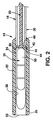
図1に示すように、搬送カテーテル10の1つの実施形態は、近位末端12と遠位末端14を有する。ハンドル16は好ましくは、カテーテルの操作を制御するために、近位末端に配置される。カテーテルは、外側管状さや18を含むカテーテル本体を有する。内部シャフト20(図2)が、外部さや18の内腔を通して伸長し、さや18と内部シャフト20が互いに対して長手方向に移動可能である。低プロファイル態様の医療機器を含むように構成されたハウジング22が、さや18の遠位末端に取り付け、遠位末端から遠位に伸長する。機器ハウジング22は、ハウジングの遠位末端にてX線不透過性マーカーバンド25によってX線透視で同定可能でありうる、開放遠位ポート23を有するチャンバー24を構成する。記述を簡単にするために、カテーテルは、カテーテルが直線であり、屈曲がない時に、カテーテルと一致する方向にそって伸長する内部軸27(図1)を有すると考慮されてよい。内部軸27は、それよりカテーテルの屈曲した遠位部分の曲線の弧が測定されうる参照として働く。機器ハウジング22は、カテーテルが直線である時に、カテーテル軸27と一列に並ぶその固有の直線軸を有すると考慮されてよい。
As shown in FIG. 1, one embodiment of the
チャンバー24は、ナビゲート可能なカテーテルによって到達可能な標的位置にて展開されるべき任意の種々の医療機器を含むように構成されている。ハウジングの直径は、折りたたまれた、低プロファイル形態にある医療機器の寸法に依存しうる。ハウジング直径が、外側さや直径に対して比較的大きく、止血弁(示していない)を備えるカテーテルインデューサさやが、ハウジングを引き込むのに十分大きい事象において、カテーテルの外部さやが、イントロデューサさやの内部直径と、外側さや18の外側直径間の環状ギャップを受け入れるために、弁リリーフ55(図7〜9)を備えて提供されてよい。弁リリーフ55は、弁リリーフと外側さや間のバックブリーディングを最小化するために、スライド可能であるが、外側さや18周辺によく適合する。
Chamber 24 is configured to contain any of a variety of medical devices that are to be deployed at a target location that is reachable by a navigable catheter. The diameter of the housing may depend on the dimensions of the medical device in a folded, low profile configuration. In an event where the catheter inducer sheath with a housing diameter that is relatively large relative to the outer sheath diameter and with a hemostasis valve (not shown) is large enough to retract the housing, the outer sheath of the catheter is inside the introducer sheath. A valve relief 55 (FIGS. 7-9) may be provided to accommodate the annular gap between the diameter and the outer diameter of the
一例として、チャンバー24は、センサ30に固定された1または2以上の固定メンバー28を含むセンサーアセンブリ26を含んでよい。固定メンバー28は、その機能を果たすために、血管壁または他の組織との係合のために、低プロファイル態様から、拡大態様に自己拡張可能であってよい。例えば、血管中の血圧を感知するように構成されアセンブリにおいて、固定メンバーは、血管に対して外傷を引き起こしうる力を適用することになしに、場所においてアセンブリを維持するのにちょうど十分な力で血管壁に係合するように構成されるのがよい。例示の目的によって、センサーアセンブリは、米国特許第S.N.13/090,854号明細書にてさらに詳細に記述される。しかしながら、本発明の利用は、センサーの展開に制限されないことが理解されるべきである。
As an example, the chamber 24 may include a
図1に示すように、カテーテルの外側さや18には、近位セグメント32、中間セグメント34および遠位セグメント36を含む種々の連続して取り付けたセグメントを有している。ハウジング22は、外側さや18の遠位セグメント36の遠位末端に取り付け、そこより遠位に伸長する。図解した実施形態において、圧力センシングアセンブリまたはペーシングシステムを含み、搬送するように構成された搬送機器に対して、ハウジング22の外側直径は、約24フレンチ(0.312インチ)のオーダーであってよい。セグメント32、34、36は、機器の近位末端から遠位末端へ徐々に柔軟性の高い構造を構成する。肺動脈中の圧力センサーアセンブリを伝達し、展開するように構成された1つの例示的例において、カテーテル本体の全長は、約110センチメートルのオーダーであってよい。カテーテルの長さが、展開の標的部位と、その部位に到達するために選択されたアプローチに依存することが理解されるべきである。
As shown in FIG. 1, the
セグメントの最も剛性で、最も長い近位セグメント32が、操縦を促進するために、カテーテルの進行と、カテーテルの近位末端から遠位末端までのトルク伝達を促進するために「プッシュ可能性」とねじれ剛性のために、カラム強度を提供する。近位セグメントは、ステンレススチール網状ワイヤから、または望むならば、網状エレメント、コイルまたは高架ワイヤのような、長手方向硬化エレメントを有しているポリマーから形成されてよい。ハンドル16は、近位セグメント32の近位末端にて取り付けられる。患者の鼠径部領域に入り、肺動脈中で機器を展開する意図があるカテーテルに関して、近位セグメント32が、長さにして約100センチメートルのオーダーであってよく、例えば、商標PEBAX7233のもと売られているポリエーテルブロックアミドコポリマーのような72 Shore D医療グレードプラスチック樹脂から形成されてよい。近位、中間および塩基セグメントの外径は、約0.144インチの内径で、約0.013インチのオーダーの壁厚を有して、約0.170インチのオーダーであってよい。近位セグメント32には、堅さまたはトルク伝達を促進することが望まれる内部網状または他の補強が含まれてよい。図解実施形態において、ハウジング22は、ハウジングの近位のカテーテル本体よりも、直径が大きいことが留意されてよい。これは、搬送されるべき医療機器の崩壊性直径の関数である。そのようなより大きな直径の機器にて、初期皮下アクセスは、穿孔皮膚と皮下組織を通してハウジングを通過させる必要があり、一旦ハウジングが大腿部動脈のような血管内に配置されたならば、ついでカテーテルが比較的小さな抵抗で進むことが可能である。
The stiffest and longest
遠位セグメント36は、もっとも短く、もっとも柔軟性の高いカテーテルのセグメントである。約3センチメートル長のオーダーであってよく、より可撓性が高く、比較的柔らかく、商標PEBAX3533にて売られているポリエーテルブロックアミドコポリマーのような35 Shore D医療グレードプラスチックレジンから形成されてよい。遠位セグメントは好ましくは、補強として可撓性が高い網状を含む。中間セグメント34は、およそ10センチメートル長であり、剛性の近位セグメント32から可撓性が高い遠位セグメント36への変移として働くために、近位および遠位セグメント32、36のものの間の堅さを有する。これは、例えば、商標PEBAX4033のもと売られているポリエーテルブロックアミドコポリマーのような、40 Shore D医療グレードプラスチック樹脂から形成されてよい。セグメントは、例えば接着剤、熱または超音波結合のような、当業者によく知られている種々の技術の任意によって、末端同士が連結されてよい。
The
管状機器ハウジング22は、外側さや18よりも直径が大きくてよく、ハウジング22の近位部分内で、遠位に向いている棚40を構成するために、重なり合い結合38において、可撓性の遠位区画36の遠位末端に取り付ける。接着結合または当業者に公知の他の好適な方法を使用して、ハウジングと遠位区画を連結してよい。ハウジング22は、低プロファイル態様の医療機器を保持するように構成され、この目的に対して好適な任意の材料から作製されるのがよい。ハウジング22は、医療機器を露出させ、放出するために、低プロファイル医療機器上を簡単にすべるように構成されるべきである。
内部シャフト20は、外側さや18の内腔を通して伸長し、以下で記述するような操作を許容するのに十分な長さだけ、外側さや18よりも長くてよい。内部シャフト20は、外側さや18を曲げるために必要な張力強度を提供するために、そしてまた、外側さや18が展開の間に引きぬかれながら、定位置に医療機器26を保持するために圧縮力を提供するために、多数の構造物の1つ内に形成されてよい。内部シャフトは、中実、管状構造、金属または重合体、または両方の組み合わせであってよく、内部シャフト内に埋め込まれるか、またはその一部として取り付けられた、編まれた、または編まれていないワイヤのような、補強エレメントを有してよい。補強エレメントは、使用される場合には、内部シャフトが張力をかけられ、その中でカテーテル10が曲がり、関節の予測方向を提供する方向に付勢する様式で組み込まれるのがよい。そのような付勢エレメントはまた、同様の目的のために外部さや18内に組み込まれてよい。
The
当接部42は、接着、溶接または他の好適な手段によってのように、内部シャフト20の遠位末端にしっかりと固定され、ハウジング22のチャンバー24内にスライド可能に含まれる。当接部42は好ましくは、X線不透過性であるか、または蛍光透視法のもとその可視性を増強するため、そしてチャンバーと医療機器の近位末端の位置の示唆を提供するために、X線不透過性マーカーとともに提供される。当接部42は、ディスク形状であり、チャンバー24の近位末端を構成する遠位表面44を有する。当接部42は、金属または剛性重合材料からのものであってよく、カテーテル内の当接部42の近位移動を制限するために、棚40と係合する近位表面46を有する。
The
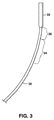
当接部42と棚40が係合するとき、内部シャフト20に適用された張力は、さや18中の長手方向圧縮力に伝達される。外側さや18の長手方向圧縮は、図3〜5に示したように、さやのセグメント32、34、36が、遠位セグメント36にて発生する最も大きな程度の屈曲、中間、遷移セグメント34にて発生しているより少ない程度の屈曲、および近位セグメント32にて発生している最も小さな程度の屈曲で曲がることを引き起こす。カテーテルの関節の程度は、内部シャフト20に適用する張力の程度を変化させることによって制御可能である。内部シャフト上の張力が開放された時に、カテーテルは弛緩し、それを通してカテーテルが展開位置内にナビゲートされる本体通路によって許可される程度まで、カテーテルコンポーネントの復元力の影響下、まっすぐになる傾向にある。医療機器を展開するために、張力が外部さや18に適用され、チャンバー24内に含まれる機器を露出させ、放出するために、内部シャフト20と当接部42に対して近位に、さやとハウジングを引き込む。したがって、外部さや18、内部シャフト20および当接部42のアレンジメントが、カテーテルの先端のたわみと、単一、二重機能機構によって、医療機器の展開を可能にする。
When the
搬送カテーテル10は、比較的少ないコンポーネントを有し、比較的簡単に作製される構造体を組み込む。1つまたは2以上のプルワイヤが、カテーテルの遠位末端に対して、常偏った取り付ける操舵可能カテーテルと対比して、本発明は、分離プルワイヤに対する必要性を避け、カテーテルの遠位末端に取り付けるべきそのようなプルワイヤを必要としない。さらに、搬送カテーテルをアセンブリする時に、外部さやが、特定の方向に屈折することを保証するために、内部シャフトを偏心位置に正確に取り付けることに注意を払う必要はない。内部シャフト20の当接部42への連結が、返信して配置されるが、本発明の機能化に必要ではない。外部さや18を長手方向に圧縮するために、内部シャフト20を引っ張ることで、さやが、上述したように関節連結することになる。外部さやが曲がる方向に所定の付勢を提供することが望まれる場合は、さやの選択された偏心部分を、所望付勢を提供するように補強するか、強化することによってこれが達成される。さらに、外部さやの選択された領域の、とりわけ遠位区画での、壁厚の違いがこの目的のために利用されてよい。外側さや18によって取られた屈曲の方向にかかわらず、カテーテル10は所望の角度方向にカテーテルを回転させることによって所定方向に向けられる。外部さや18は、カテーテル近位末端12から、カテーテル遠位末端14への回転の伝送を促進するように、ねじれ剛性を提供するように構築される。
The
本発明は、かなりの角度の関節接合を可能にする。図3〜5は、張力をかけられた内部シャフト20と当接部42によって外部さや18にかけられた徐々に増加する圧縮負荷でのカテーテルの部分の相対関節接合を示している。図3は、相対的に低レベルの張力が内部シャフト20に適用された時の曲線の程度を示している。図4は、張力のレベルの増加に伴う態様を示しており、図5はさらに増加した張力レベルでの態様を示している。ハウジング22は、外部さや18にかけられた圧縮負荷がかけられず、さやの圧縮負荷のいたる所で、その直線管状形状のままである。圧縮負荷が増加するにつれて、ハウジング22は徐々に、直線軸27に対して増加角度に方向付けられる。図5に見られるように、ハウジング22は、直線軸27に対して約180度の角度を通して再方向付けされた。したがって、示したように、近位セグメント32が直線軸から離れて曲がってよい程度まで、最も大きな半径と、最小の量の屈曲を有し、中間セグメント34は、より小さな半径を有するより大きな程度の屈曲を提示し、遠位セグメント36は、最も小さな半径を有する最も大きな程度の屈曲を受ける。内部シャフト20への張力を変えることによって、そしてカテーテルを回転させることによって、ハウジング22の方向を、展開部位までの選択された経路にそって、搬送カテーテルを操縦させることを促進するように制御可能に指向することが可能である。
The present invention allows for a significant angle of articulation. FIGS. 3-5 show the relative articulation of the portion of the catheter with a gradually increasing compressive load applied to the
搬送カテーテル10が、意図した標的部位でハウジング22を配置するために進められ、臨床医が医療機器が開放可能であることを決定した後、内部シャフト20の位置を維持される一方、外部さや18とハウジング22を近位に引っ込め、血管内で展開させながら自己拡張を許容するように、医療機器26を徐々に露出させる(図7を参照のこと、以下で議論する)。解放の間、患者内の医療機器の位置は、その近位末端の当接部42との係合によって維持される(図2)。さや18の引き込みが開始されると、内部シャフト18の張力が解放され、カテーテルは、それを通してカテーテルが標的部位に達するように進む経路によって構成された弛緩態様を自由に想定することができる。
After
近位末端12でのハンドル16が、カテーテルの操作を制御する。図6で示すように、ハンドル16には、その中で長手方向の滑り移動のためのスライド50を含むハウジング48が含まれる。スライド50は、ハンドルハウジング48中の長手方向スロット54を通して横に伸長し、スライド50を前後に動かすために臨床医によって操作されてよい外部アクセス可能ボタン52を構成する部分を有する。スライド50は、内部シャフト20の近位末端近くに取り付けし、内部さや18の近位末端がハウジング48に固定される。コンポーネントは、ボタンとスライドが、内部シャフト20が引っ張られず、当接部42が、棚40に対してその近位位置にあるスロット54にそって、中途の中立位置を有するようにアレンジされる。したがって、このアレンジにおいて、内部シャフトが引っ張られて、中立位置から近位方向に、ハンドルハウジング48に対してスライド50を引き込みをすることによって、カテーテル10の遠位末端を屈折させる。近位方向にて、スライド50に対してハンドルハウジング48を引き込むことによって、患者の生体構造中の医療機器26の位置が維持され、一方でさや18とハウジング22が、医療機器を展開するために引き抜かれることを引き起こす。
A
内部シャフト20が、スロット54の近位でハウジング48に連結され、外部さや18の近位末端が、ハウジング48内で軸方向に移動可能なようにスライド50に連結され、逆のアレンジメント(示していない)が使用され、伸長とさや引き込むための操作の逆モードがもたらされる。例えば、逆アレンジメントにおいて、中立位置から近位方向に、ハウジング48に対してスライド50を引き込むことにより、患者の生体構造内の医療機器26の位置が維持され、一方で、さや18とハウジング22が、医療機器を展開するために引き抜かれることが引き起こされる。
The
ハンドル16には、図6で略図的に示し、以下でさらに詳細に議論する、Tuohy−Borst型のフィッティング56と、フラッシングまたは他の目的のためのように、流体がカテーテルを通して通過可能にするために、内部シャフト20の内腔と連絡する側面ポート57が含まれてよい。図6で図解したように、チューブ58がハウジング48内で固定され、その間にスライディングシールを形成するために、空間内部シャフト20の近位末端を受領する。したがって、側面ポート57が、チューブ58の内部とハンドルハウジング48のチャンバー59を介して、内部シャフト20の内腔と流動的に連絡する。また外側さや18と機器ハウジング22の内腔をフラッシュするために、1つまたはそれ以上のポート(示していない)が、内部シャフトの長さにそって、一般に中途に、内部シャフト20の壁を通して提供されてよい。本実施形態において、側面ポート57内に注入された液体は、空洞内部シャフト20の内腔を通して、そしてシャフト20内のフラッシュポートを通して、外側さや18の内腔に流れる。空気が、したがって、内部シャフト20の遠位末端と、外側さや18の両末端から押し出されうる。
The
図7〜9は、埋込可能機器が正しく展開されないか、または正確な位置にないと決定された場合、部分的に展開された医療機器26をハウジング22内に再捕獲可能である、本発明の改変実施形態を略図的に示している。再捕獲に際して、医療機器26を再配置および再展開するか、または患者から取り除くことが可能である。本実施形態において、縫合糸またはワイヤつなぎ網48が、搬送カテーテル10を通して、好ましくは管状内部シャフト20の内腔を通して伸長し、つなぎ網は、その遠位末端に湾曲部50を、そしてハンドル16の近位末端にてフィッティング56から突起している一組の遊離尾52を構成するために二重である。つなぎ網48は、湾曲部50がそれに取り付けるように、医療機器中の開口部を通して通過する。開口部はまた、二重つなぎ網48が、当接部を通してチャンバー24内へ通過することを許容するように、当接部42内に形成される。フィッティング56は、圧縮可能エレメントで、つなぎ網をグリップするか、放出するためにねじることが可能なTuohy−Borst型の機器のような、遊離尾52をクランプするか、または放出するために調節可能である型のものである。カテーテル10が、医療機器26を搬送する準備が出来た時に、機器は、機器の近位末端中の開口部から伸長するつなぎ網48と、位置にそれらをロックするためのつなぎ網48の尾52周辺に締め付けられたフィッティング56にて、ハウジング22中の低プロファイル態様中に含まれる。カテーテルが、意図した展開部にてハウジング22を配置するためにナビゲートされた後、ハンドル中のスライドが、医療機器が血管または他の標的組織と係合することを許容するために、さやを引くように操作される(図8)。この接合点にて、臨床医は、X線透視にて、機器の位置と方向を観察しうる。臨床医が機器の配置に満足したならば、フィッティング56が開放されてつなぎ網48上のグリップが放出され、尾52の1つが引かれて引き抜かれ、医療機器の開口部との係合から、つなぎ網が引き抜かれて、糸を抜く(図9)。しかしながら配置が満足にいたらないとわかった場合、ついで、さや18とカプセル22がつなぎ網48上を遠位に進み、チャンバー24内の機器26を再捕獲可能である。再捕獲移動は、それらがチャンバー24内に引かれるので、固定メンバー28を圧縮することによって、医療機器26を低プロファイル態様に変換しなおす。カテーテルをついで再配置可能であり、再展開された機器、または全アセンブリが患者から除去されうる。
FIGS. 7-9 illustrate the present invention in which a partially deployed
以上から、本発明が、比較的少ないコンポーネントを持つ単純化された構造のものであり、簡単に構築される医療機器に対する、搬送カテーテルを提供することが理解されるであろう。カテーテルは、そのカテーテルをナビゲートするための別のガイドワイヤ、またはカテーテルの遠位末端の屈曲を制御するための別のプルワイヤの必要性を回避する。それによってカテーテルが開放される単独の機構が、医療機器の先端屈曲と展開の両方の機能を制御する。本発明の以上の記述が、例示の目的のみ意図されること、および他の実施形態、改変および等価物が、本発明の原理から逸脱せずに明らかになることが理解されるべきである。 From the foregoing, it will be appreciated that the present invention provides a delivery catheter for a medical device that is of a simplified construction with relatively few components and is easily constructed. The catheter avoids the need for a separate guidewire to navigate the catheter or a separate pullwire to control the bending of the distal end of the catheter. A single mechanism whereby the catheter is opened controls both the tip bending and deployment functions of the medical device. It should be understood that the foregoing description of the invention is intended for purposes of illustration only, and that other embodiments, modifications, and equivalents will become apparent without departing from the principles of the invention.
Claims (17)
近位および遠位末端と直線軸を有する細長い管状外部さやと、
前記さやの遠位末端にマウントされたハウジングで、医療機器を含むように構成されたチャンバーを構成し、その遠位末端で開放遠位ポートを有するハウジングと、
前記さやを通して伸長している内部シャフトで、張力のもとで広げられない内部シャフトと、
前記内部シャフトの遠位末端に固定された当接部で、前記チャンバー内に配置され、前記チャンバーの近位末端を構成し、前記内部シャフトと当接部は、前記さやとハウジングに対して長手方向に移動可能である当接部と、を備え、
前記外部さやが、前記ハウジングの近位領域と前記当接部の近位に隣接した棚を有し、前記棚が、前記内部シャフトの伸長に対する応答で、外部さやに圧縮負荷を適用するために、前記当接部の近位に面している表面によって係合させられるように構成され、
前記外部さやは、近位末端にて適用された回転を、遠位末端に制御可能に伝送するための十分にねじれに剛であり、
前記外部さやは、前記棚に対して、前記当接部によって適用された前記圧縮負荷のもと、直線軸から長手方向に離れて屈曲するように構築され、屈曲の程度が、さやにかけられた圧縮負荷の程度に対応し、
前記外部さやは、前記当接部に対して引き込み可能であり、前記外部さやを引き込むことによって、チャンバー内に含まれる医療機器が、前記当接部に対して、選択された位置で少なくとも部分的に展開される、
ことを特徴とする操舵可能型カテーテル。 A steerable catheter for transporting and deploying medical devices,
An elongated tubular outer sheath having proximal and distal ends and a linear axis;
A housing mounted at the distal end of the sheath, wherein the housing is configured to contain a medical device and has an open distal port at the distal end;
An internal shaft that extends through the sheath, and the inner shaft without wide Gerare under tension,
An abutment fixed to the distal end of the inner shaft is disposed within the chamber and constitutes a proximal end of the chamber, the inner shaft and the abutment being elongated relative to the sheath and housing A contact portion movable in a direction,
The outer sheath has a shelf adjacent to the proximal region of the housing and proximal to the abutment, and the shelf applies a compressive load to the outer sheath in response to extension of the inner shaft; Configured to be engaged by a proximally facing surface of the abutment,
The outer sheath is sufficiently torsionally rigid to controllably transmit the rotation applied at the proximal end to the distal end;
The outer sheath, relative to the shelf, the original applied the compressive loading by abutment are constructed to be bent away from the linear axis in the longitudinal direction, the degree of bending was subjected to sheath Corresponding to the degree of compression load ,
The outer sheath is retractable with respect to the abutment, and by retracting the outer sheath, the medical device contained within the chamber is at least partially at a selected position relative to the abutment. Expanded to
A steerable catheter characterized by the above.
請求項1に記載のカテーテル。 The outer sheath is configured to increase flexibility in a distal direction;
The catheter according to claim 1.
請求項2に記載のカテーテル。 The outer sheath is formed from a number of consecutively connected segments, the most distal of the segment being the most flexible and exhibiting the greatest degree of longitudinal bending as the sheath is pressurized;
The catheter according to claim 2.
請求項3に記載のカテーテル。 The outer sheath has at least three segments including a proximal segment, a shorter intermediate segment, and an even shorter distal segment, the housing being relatively inflexible and distal to the distal segment Extending distally from the end,
The catheter according to claim 3.
請求項2に記載のカテーテル。 The outer sheath is bendable in response to extension of the inner shaft to form an angle of at least about 90 degrees between the axis of the housing and the linear axis;
The catheter according to claim 2.
請求項2に記載のカテーテル。 The outer sheath is bendable in response to extension of the inner shaft to form an angle of at least about 180 degrees between the axis of the housing and the linear axis;
The catheter according to claim 2.
請求項1に記載のカテーテル。 Said shelves are constituted by the distal end of the distal segment of the sheath, mounted proximal end of said housing, with sheath disposed within the housing, the distal end and its vicinity of said distal segment Be
The catheter according to claim 1.
請求項7に記載のカテーテル。 Wherein the abutment is annular and the abutment is in the shape of a disc having a diameter for adjoining the abutment;
The catheter according to claim 7.
請求項1に記載のカテーテル。 The inner shaft includes a lumen extending along its length, and the abutment has an opening in communication with the lumen so that the tether is from a medical device in the chamber; Extendable to the proximal end of the catheter;
The catheter according to claim 1.
請求項9に記載のカテーテル。 And a clamp at a proximal end of the catheter, the clamp configured to receive and releasably clamp the proximal end of the tether.
The catheter according to claim 9.
請求項1に記載のカテーテル。 The abutment is radiopaque to allow the position of the proximal end of the chamber to be determined by radiographic transmission when the chamber is loaded with a medical device;
The catheter according to claim 1.
請求項11に記載のカテーテル。 In addition, a radiopaque marker band located at the distal end of the housing is included.
The catheter according to claim 11.
さやの近位末端が、前記ハンドルまたは前記スライドの1つと取り付けられ、および
前記内部シャフトの近位末端が、他の前記ハンドルまたは前記スライドと取り付けられる、
請求項1に記載のカテーテル。 A handle at the proximal end of the catheter, comprising a slide mounted for longitudinal movement, the slide being operable outside the handle;
The proximal end of the sheath is attached to one of the handle or the slide, and the proximal end of the inner shaft is attached to the other handle or the slide;
The catheter according to claim 1.
請求項13に記載のカテーテル。 And a side port mounted on the handle in communication with an internal shaft to allow fluid connection between the proximal and distal ends of the catheter.
The catheter according to claim 13.
近位および遠位末端を有する管状外部さやと、
前記さやの遠位末端にマウントされたハウジングで、医療機器を含むように構成されたチャンバーを構成しており、その遠位末端に開放遠位ポートを有するハウジングと、
前記さやを通して伸長している内部シャフトで、張力で比較的広げられない内部シャフトと、
前記シャフトの遠位末端に固定された当接部で、前記チャンバー内に配置され、前記チャンバーの近位末端を構成し、前記内部シャフトと当接部は、前記さやとハウジングに対して、長手方向に移動可能である当接部と、を備え、
前記外部さやが、前記ハウジングの近位領域と前記当接部の近位に隣接した棚を有し、前記棚が、前記当接部の近位に面する表面によって係合され、前記内部シャフトの伸長に応答して外部さやに圧縮負荷を適用するように構成され、
前記外部さやが、前記棚に対して、前記当接部によって適用された前記圧縮負荷のもと、前記さやが長手方向に屈曲することを可能にするための手段を有し、
屈曲の程度が、前記さやに適合された圧縮負荷の程度に対応し、
前記外部さやが、前記当接部に対して引き込む可能であり、それによって前記外部さやを引き込むことによって、チャンバー内に含まれる医療機器が、前記当接部に対して選択された位置にて少なくとも部分的に展開される、
ことを特徴とする操舵可能型カテーテル。 A steerable catheter for transporting and deploying medical devices,
A tubular outer sheath having proximal and distal ends;
A housing mounted at the distal end of the sheath, wherein the housing is configured to contain a medical device and has an open distal port at the distal end;
An internal shaft extending through the sheath, and an internal shaft that is relatively unexpanded by tension;
An abutment fixed to the distal end of the shaft, disposed within the chamber and constituting a proximal end of the chamber, the inner shaft and the abutment being longitudinal with respect to the sheath and housing; A contact portion movable in a direction,
The outer sheath has a shelf adjacent to the proximal region of the housing and proximal to the abutment, the shelf being engaged by a proximally facing surface of the abutment; Configured to apply a compression load to the outer sheath in response to stretching
Said external sheath is relative to the shelf, the original applied the compressive loading by abutment, and means for allowing the sheath to bend in the longitudinal direction,
The degree of bending corresponds to the degree of compressive load adapted to the sheath,
The external sheath is retractable with respect to the abutment, thereby retracting the external sheath so that the medical device contained within the chamber is at least selected at a position relative to the abutment. Partially expanded,
A steerable catheter characterized by the above.
近位および遠位末端を有する管状外部さやと、
前記さやの遠位末端にマウントされたハウジングで、医療機器を含むように適合したチャンバーを構成しており、その遠位末端にて、開放遠位ポートを有するハウジングと、
前記さやを通して伸長している内部シャフトで、張力のもとで比較的広げられない内部シャフトと、
前記シャフトの遠位末端に固定された当接部で、前記チャンバー内に配置され、前記チャンバーの近位末端を構成し、前記内部シャフトと当接部は、前記さやとハウジングに対して、長手方向に移動可能である当接部と、を備え、
前記外部さやが、前記ハウジングの近位領域と前記当接部の近位に隣接した棚を有し、前記棚が、前記内部シャフトの伸長に応答して、外部さやに圧縮負荷を適用するために、前記当接部の近位に面する表面によって係合されるように構成され、
前記外部さやが、前記棚に対して、前記当接部によって適用された前記圧縮負荷のもと、前記さやが長手方向に屈曲することを可能にするための手段を有し、屈曲の程度が、前記さやに適合された圧縮負荷の程度に対応し、前記さやは約180度の少なくとも2つの屈曲を含む経路を通して、屈曲可能で、ナビゲート可能であり、
前記外部さやが前記当接部に対して引き込む可能であり、前記外部さやを引き込むことによって、チャンバー内に含まれる医療機器が、前記当接部に対して、選択された位置で少なくとも部分的に展開される、
ことを特徴とする操舵可能型カテーテル。 A steerable catheter for transporting and deploying medical devices through the femoral vein at least on the right side of the patient's heart,
A tubular outer sheath having proximal and distal ends;
A housing mounted at a distal end of the sheath, wherein the chamber is adapted to contain a medical device and has a housing having an open distal port at the distal end;
An internal shaft extending through the sheath, which is relatively unexpanded under tension;
An abutment fixed to the distal end of the shaft, disposed within the chamber and constituting a proximal end of the chamber, the inner shaft and the abutment being longitudinal with respect to the sheath and housing; A contact portion movable in a direction,
The outer sheath has a shelf adjacent to the proximal region of the housing and proximal to the abutment, the shelf applying a compressive load to the outer sheath in response to extension of the inner shaft; And is configured to be engaged by a proximally facing surface of the abutment
Said external sheath is relative to the shelf, the original applied the compressive loading by abutment, and means for allowing the sheath to bend in the longitudinal direction, the degree of bending corresponds to the degree of adapted compressive load to said sheath, said sheath through path including at least two bends of about 180 degrees, bendable, are navigable,
The external sheath is retractable relative to the abutment, and by retracting the external sheath, the medical device contained within the chamber is at least partially at a selected position relative to the abutment. Be expanded,
A steerable catheter characterized by the above.
請求項16に記載のカテーテル。 The catheter has a length sufficient to reach the pulmonary artery;
The catheter according to claim 16.
Applications Claiming Priority (3)
| Application Number | Priority Date | Filing Date | Title |
|---|---|---|---|
| US13/176,193 US8926588B2 (en) | 2011-07-05 | 2011-07-05 | Steerable delivery catheter |
| US13/176,193 | 2011-07-05 | ||
| PCT/US2012/043575 WO2013006282A1 (en) | 2011-07-05 | 2012-06-21 | Steerable delivery catheter |
Publications (3)
| Publication Number | Publication Date |
|---|---|
| JP2014520598A JP2014520598A (en) | 2014-08-25 |
| JP2014520598A5 JP2014520598A5 (en) | 2015-08-13 |
| JP5830794B2 true JP5830794B2 (en) | 2015-12-09 |
Family
ID=46457086
Family Applications (1)
| Application Number | Title | Priority Date | Filing Date |
|---|---|---|---|
| JP2014518664A Active JP5830794B2 (en) | 2011-07-05 | 2012-06-21 | Steerable delivery catheter |
Country Status (6)
| Country | Link |
|---|---|
| US (1) | US8926588B2 (en) |
| EP (1) | EP2729093B1 (en) |
| JP (1) | JP5830794B2 (en) |
| CN (1) | CN103635160B (en) |
| BR (1) | BR112013033875A2 (en) |
| WO (1) | WO2013006282A1 (en) |
Families Citing this family (99)
| Publication number | Priority date | Publication date | Assignee | Title |
|---|---|---|---|---|
| US8579964B2 (en) | 2010-05-05 | 2013-11-12 | Neovasc Inc. | Transcatheter mitral valve prosthesis |
| US9308087B2 (en) | 2011-04-28 | 2016-04-12 | Neovasc Tiara Inc. | Sequentially deployed transcatheter mitral valve prosthesis |
| US9554897B2 (en) | 2011-04-28 | 2017-01-31 | Neovasc Tiara Inc. | Methods and apparatus for engaging a valve prosthesis with tissue |
| US9572481B2 (en) | 2011-05-13 | 2017-02-21 | Intuitive Surgical Operations, Inc. | Medical system with multiple operating modes for steering a medical instrument through linked body passages |
| US9345573B2 (en) | 2012-05-30 | 2016-05-24 | Neovasc Tiara Inc. | Methods and apparatus for loading a prosthesis onto a delivery system |
| US20140052109A1 (en) * | 2012-08-19 | 2014-02-20 | Diros Technology Inc. | Steerable Multifunction Catheter Probe with High Guidability and Reversible Rigidity |
| US9233225B2 (en) | 2012-11-10 | 2016-01-12 | Curvo Medical, Inc. | Coaxial bi-directional catheter |
| EP2922592B1 (en) * | 2012-11-21 | 2022-09-21 | Edwards Lifesciences Corporation | Retaining mechanisms for prosthetic heart valves |
| ITPD20130020A1 (en) * | 2013-01-30 | 2014-07-31 | Gioachino Coppi | VARIABLE BEND CATHETER |
| US9572665B2 (en) | 2013-04-04 | 2017-02-21 | Neovasc Tiara Inc. | Methods and apparatus for delivering a prosthetic valve to a beating heart |
| US10071243B2 (en) | 2013-07-31 | 2018-09-11 | Medtronic, Inc. | Fixation for implantable medical devices |
| US9492674B2 (en) | 2013-08-16 | 2016-11-15 | Cardiac Pacemakers, Inc. | Leadless cardiac pacemaker with delivery and/or retrieval features |
| US10722723B2 (en) * | 2013-08-16 | 2020-07-28 | Cardiac Pacemakers, Inc. | Delivery devices and methods for leadless cardiac devices |
| US10842993B2 (en) | 2013-08-16 | 2020-11-24 | Cardiac Pacemakers, Inc. | Leadless cardiac pacing devices |
| EP3033141B1 (en) | 2013-08-16 | 2017-10-11 | Cardiac Pacemakers, Inc. | Leadless cardiac pacing devices |
| US9480850B2 (en) | 2013-08-16 | 2016-11-01 | Cardiac Pacemakers, Inc. | Leadless cardiac pacemaker and retrieval device |
| EP3338856B1 (en) | 2013-08-16 | 2021-08-04 | Cardiac Pacemakers, Inc. | Delivery devices for leadless cardiac devices |
| US9393427B2 (en) | 2013-08-16 | 2016-07-19 | Cardiac Pacemakers, Inc. | Leadless cardiac pacemaker with delivery and/or retrieval features |
| JP6182675B2 (en) | 2013-08-16 | 2017-08-16 | カーディアック ペースメイカーズ, インコーポレイテッド | Leadless cardiac pacemaker and collection device |
| US20150119847A1 (en) * | 2013-10-29 | 2015-04-30 | Medwerks, Llc | Atraumatic Guidewire And Method Of Use |
| US9572666B2 (en) | 2014-03-17 | 2017-02-21 | Evalve, Inc. | Mitral valve fixation device removal devices and methods |
| US10080887B2 (en) | 2014-04-29 | 2018-09-25 | Cardiac Pacemakers, Inc. | Leadless cardiac pacing devices including tissue engagement verification |
| WO2015168155A1 (en) | 2014-04-29 | 2015-11-05 | Cardiac Pacemakers, Inc. | Leadless cardiac pacemaker with retrieval features |
| US10716931B2 (en) | 2014-09-09 | 2020-07-21 | Pacesetter, Inc. | Systems and methods for implanting a medical device |
| US10441777B2 (en) | 2014-09-09 | 2019-10-15 | Pacesetter, Inc. | Implantable medical device having restrained tether device |
| CN106852124A (en) | 2014-10-22 | 2017-06-13 | 心脏起搏器股份公司 | For the delivery device and method of leadless cardiac equipment |
| WO2016065058A1 (en) | 2014-10-22 | 2016-04-28 | Cardiac Pacemakers, Inc. | Delivery devices for leadless cardiac devices |
| US20160206872A1 (en) * | 2015-01-16 | 2016-07-21 | Medtronic, Inc. | Interventional medical tools and assemblies |
| US9937322B2 (en) | 2015-04-23 | 2018-04-10 | Medtronic, Inc. | Assemblies and methods for deflectable shaft catheters |
| US9867964B2 (en) | 2015-04-23 | 2018-01-16 | Medtronic, Inc. | Interventional medical systems, assemblies, and construction methods |
| CN107592821B (en) * | 2015-05-13 | 2021-11-23 | 美敦力公司 | Securing an implantable medical device in place while reducing perforation |
| US10143838B2 (en) | 2015-05-13 | 2018-12-04 | Medtronic, Inc. | Securing an implantable medical device in position while reducing perforations |
| US10376673B2 (en) | 2015-06-19 | 2019-08-13 | Evalve, Inc. | Catheter guiding system and methods |
| US10525256B2 (en) * | 2015-07-29 | 2020-01-07 | Medtronic, Inc. | Interventional medical systems, catheters, and methods |
| US10080862B2 (en) * | 2015-08-14 | 2018-09-25 | Medtronic, Inc. | Tubular bodies for medical delivery devices and related manufacturing methods |
| CN108348759B (en) * | 2015-11-20 | 2021-08-17 | 心脏起搏器股份公司 | Delivery devices and methods for leadless cardiac devices |
| EP3377173B1 (en) | 2015-11-20 | 2024-08-21 | Cardiac Pacemakers, Inc. | Delivery devices for leadless cardiac devices |
| JP7002466B2 (en) * | 2015-12-30 | 2022-01-20 | パイプライン メディカル テクノロジーズ,インコーポレイティド | Mitral valve binding |
| US10463853B2 (en) | 2016-01-21 | 2019-11-05 | Medtronic, Inc. | Interventional medical systems |
| US10099050B2 (en) | 2016-01-21 | 2018-10-16 | Medtronic, Inc. | Interventional medical devices, device systems, and fixation components thereof |
| US10433952B2 (en) | 2016-01-29 | 2019-10-08 | Neovasc Tiara Inc. | Prosthetic valve for avoiding obstruction of outflow |
| US20210212824A1 (en) * | 2016-03-08 | 2021-07-15 | Dura Llc | Heart valve leaflet replacement devices and multi-stage, multi-lumen heart valve delivery systems and method for use |
| US10278852B2 (en) | 2016-03-10 | 2019-05-07 | Medtronic Vascular, Inc. | Steerable catheter with multiple bending radii via a steering mechanism with telescoping tubular components |
| US10736632B2 (en) | 2016-07-06 | 2020-08-11 | Evalve, Inc. | Methods and devices for valve clip excision |
| US10661052B2 (en) | 2016-07-29 | 2020-05-26 | Cephea Valve Technologies, Inc. | Intravascular device delivery sheath |
| US10646689B2 (en) | 2016-07-29 | 2020-05-12 | Cephea Valve Technologies, Inc. | Mechanical interlock for catheters |
| CN207708054U (en) * | 2016-07-29 | 2018-08-10 | 上海沃比医疗科技有限公司 | Implantation material transport system |
| US10639151B2 (en) | 2016-07-29 | 2020-05-05 | Cephea Valve Technologies, Inc. | Threaded coil |
| US10974027B2 (en) | 2016-07-29 | 2021-04-13 | Cephea Valve Technologies, Inc. | Combination steerable catheter and systems |
| US11324495B2 (en) | 2016-07-29 | 2022-05-10 | Cephea Valve Technologies, Inc. | Systems and methods for delivering an intravascular device to the mitral annulus |
| US10933216B2 (en) * | 2016-08-29 | 2021-03-02 | Cephea Valve Technologies, Inc. | Multilumen catheter |
| US11109967B2 (en) | 2016-08-29 | 2021-09-07 | Cephea Valve Technologies, Inc. | Systems and methods for loading and deploying an intravascular device |
| US11045315B2 (en) | 2016-08-29 | 2021-06-29 | Cephea Valve Technologies, Inc. | Methods of steering and delivery of intravascular devices |
| US10751485B2 (en) | 2016-08-29 | 2020-08-25 | Cephea Valve Technologies, Inc. | Methods, systems, and devices for sealing and flushing a delivery system |
| US10874512B2 (en) | 2016-10-05 | 2020-12-29 | Cephea Valve Technologies, Inc. | System and methods for delivering and deploying an artificial heart valve within the mitral annulus |
| US11071564B2 (en) | 2016-10-05 | 2021-07-27 | Evalve, Inc. | Cardiac valve cutting device |
| US11198013B2 (en) | 2016-11-21 | 2021-12-14 | Cardiac Pacemakers, Inc. | Catheter and leadless cardiac devices including electrical pathway barrier |
| EP3541462A4 (en) | 2016-11-21 | 2020-06-17 | Neovasc Tiara Inc. | Methods and systems for rapid retraction of a transcatheter heart valve delivery system |
| US10905465B2 (en) | 2016-11-21 | 2021-02-02 | Cardiac Pacemakers, Inc. | Delivery devices and wall apposition sensing |
| KR20200010161A (en) | 2016-11-22 | 2020-01-30 | 시네코어 엘엘씨 | Visiblewire septal transit system for treatment of mitral valve |
| CN110114114B (en) | 2016-12-27 | 2023-05-02 | 心脏起搏器股份公司 | Delivery devices and methods for leadless cardiac devices |
| JP6796727B2 (en) | 2016-12-27 | 2020-12-09 | カーディアック ペースメイカーズ, インコーポレイテッド | Leadless delivery catheter with conduction path |
| US10806931B2 (en) | 2016-12-27 | 2020-10-20 | Cardiac Pacemakers, Inc. | Delivery devices and methods for leadless cardiac devices |
| US10485981B2 (en) | 2016-12-27 | 2019-11-26 | Cardiac Pacemakers, Inc. | Fixation methods for leadless cardiac devices |
| US10925731B2 (en) | 2016-12-30 | 2021-02-23 | Pipeline Medical Technologies, Inc. | Method and apparatus for transvascular implantation of neo chordae tendinae |
| US9877833B1 (en) | 2016-12-30 | 2018-01-30 | Pipeline Medical Technologies, Inc. | Method and apparatus for transvascular implantation of neo chordae tendinae |
| US11083580B2 (en) | 2016-12-30 | 2021-08-10 | Pipeline Medical Technologies, Inc. | Method of securing a leaflet anchor to a mitral valve leaflet |
| CN108261256B (en) * | 2016-12-31 | 2024-05-07 | 深圳市健心医疗科技有限公司 | Conveying device and conveying system |
| US10773089B2 (en) | 2017-01-26 | 2020-09-15 | Cardiac Pacemakers, Inc. | Delivery devices and methods for leadless cardiac devices |
| US11229798B2 (en) | 2017-03-10 | 2022-01-25 | Cardiac Pacemakers, Inc. | Fixation for leadless cardiac devices |
| US10737092B2 (en) | 2017-03-30 | 2020-08-11 | Cardiac Pacemakers, Inc. | Delivery devices and methods for leadless cardiac devices |
| US11577085B2 (en) | 2017-08-03 | 2023-02-14 | Cardiac Pacemakers, Inc. | Delivery devices and methods for leadless cardiac devices |
| WO2019055154A2 (en) | 2017-08-06 | 2019-03-21 | Synecor Llc | Systems and methods for transseptal delivery of therapeutic devices of the heart |
| US10856984B2 (en) | 2017-08-25 | 2020-12-08 | Neovasc Tiara Inc. | Sequentially deployed transcatheter mitral valve prosthesis |
| MX2021002377A (en) * | 2018-08-29 | 2021-07-21 | Ernesto Molmenti | Knot-tying device for surgical sutures. |
| CN110947096B (en) * | 2018-09-27 | 2021-09-03 | 创领心律管理医疗器械(上海)有限公司 | Cardiac pacing system and pacemaker fixing device |
| US10894144B2 (en) * | 2018-10-16 | 2021-01-19 | Pacesetter, Inc. | Apparatus and method for sensor deployment and fixation |
| AU2019374743B2 (en) | 2018-11-08 | 2022-03-03 | Neovasc Tiara Inc. | Ventricular deployment of a transcatheter mitral valve prosthesis |
| US11724068B2 (en) | 2018-11-16 | 2023-08-15 | Cephea Valve Technologies, Inc. | Intravascular delivery system |
| CN113286566A (en) | 2018-12-12 | 2021-08-20 | 管道医疗技术公司 | Method and apparatus for mitral chordae repair |
| US11000637B2 (en) | 2019-02-07 | 2021-05-11 | Synecor Llc | Systems and methods for transseptal delivery of percutaneous ventricular assist devices and other non-guidewire based transvascular therapeutic devices |
| EP3934591A4 (en) | 2019-03-08 | 2022-11-23 | Neovasc Tiara Inc. | Retrievable prosthesis delivery system |
| JP2022522690A (en) * | 2019-03-15 | 2022-04-20 | バイオトロニック エスエー アンド カンパニー カーゲー | Catheter device for implanting medical devices |
| US11759632B2 (en) | 2019-03-28 | 2023-09-19 | Medtronic, Inc. | Fixation components for implantable medical devices |
| EP3946568A1 (en) | 2019-03-29 | 2022-02-09 | Cardiac Pacemakers, Inc. | Systems and methods for treating cardiac arrhythmias |
| WO2020205397A1 (en) | 2019-03-29 | 2020-10-08 | Cardiac Pacemakers, Inc. | Systems and methods for treating cardiac arrhythmias |
| JP7438236B2 (en) | 2019-04-01 | 2024-02-26 | ニオバスク ティアラ インコーポレイテッド | Controllably deployable prosthetic valve |
| CA3136334A1 (en) | 2019-04-10 | 2020-10-15 | Neovasc Tiara Inc. | Prosthetic valve with natural blood flow |
| CN114025813B (en) | 2019-05-20 | 2024-05-14 | 内奥瓦斯克迪亚拉公司 | Introducer with hemostatic mechanism |
| CN114144144A (en) | 2019-06-20 | 2022-03-04 | 内奥瓦斯克迪亚拉公司 | Low-profile prosthetic mitral valve |
| EP3986520A1 (en) * | 2019-06-24 | 2022-04-27 | Medtronic, Inc. | Catheter handle with torque mechanism and valve relief component |
| US11524139B2 (en) | 2019-07-15 | 2022-12-13 | Medtronic, Inc. | Catheter with active return curve |
| US11524143B2 (en) | 2019-07-15 | 2022-12-13 | Medtronic, Inc. | Catheter with distal and proximal fixation members |
| WO2021050679A1 (en) | 2019-09-11 | 2021-03-18 | Cardiac Pacemakers, Inc. | Tools and systems for implanting and/or retrieving a leadless cardiac pacing device with helix fixation |
| US11571582B2 (en) | 2019-09-11 | 2023-02-07 | Cardiac Pacemakers, Inc. | Tools and systems for implanting and/or retrieving a leadless cardiac pacing device with helix fixation |
| US12048448B2 (en) | 2020-05-06 | 2024-07-30 | Evalve, Inc. | Leaflet grasping and cutting device |
| US11872357B2 (en) | 2020-11-09 | 2024-01-16 | Agile Devices, Inc. | Devices for steering catheters |
| EP4284282A1 (en) * | 2021-03-16 | 2023-12-06 | AtriCure, Inc. | Delivery devices and related methods |
| DE102021132097A1 (en) | 2021-12-06 | 2023-06-07 | Optimed Medizinische Instrumente Gmbh | Hand unit for delivering and releasing an implant |
Family Cites Families (16)
| Publication number | Priority date | Publication date | Assignee | Title |
|---|---|---|---|---|
| US2007626A (en) | 1933-04-14 | 1935-07-09 | Vadsco Salcs Corp | Capsule applicator |
| US3334629A (en) | 1964-11-09 | 1967-08-08 | Bertram D Cohn | Occlusive device for inferior vena cava |
| US4588395A (en) | 1978-03-10 | 1986-05-13 | Lemelson Jerome H | Catheter and method |
| US4512338A (en) | 1983-01-25 | 1985-04-23 | Balko Alexander B | Process for restoring patency to body vessels |
| US5372587A (en) * | 1989-01-09 | 1994-12-13 | Pilot Cariovascular Systems, Inc. | Steerable medical device |
| US5147379A (en) | 1990-11-26 | 1992-09-15 | Louisiana State University And Agricultural And Mechanical College | Insertion instrument for vena cava filter |
| US5397321A (en) * | 1993-07-30 | 1995-03-14 | Ep Technologies, Inc. | Variable curve electrophysiology catheter |
| FR2718345B1 (en) | 1994-04-11 | 1997-04-04 | Braun Celsa Sa | Handle for controlled relative sliding of a sheath and a rod and apparatus for implanting a medical device, such as a filter, using such a handle. |
| US5743874A (en) * | 1994-08-29 | 1998-04-28 | Fischell; Robert E. | Integrated catheter for balloon angioplasty and stent delivery |
| US5674271A (en) * | 1996-11-14 | 1997-10-07 | Denker; Stephen | Catheter with steerable stylet |
| WO2001076680A1 (en) * | 2000-04-05 | 2001-10-18 | Stx Medical, Inc. | Intralumenal material removal systems and methods |
| US6773446B1 (en) | 2000-08-02 | 2004-08-10 | Cordis Corporation | Delivery apparatus for a self-expanding stent |
| US6607496B1 (en) * | 2000-09-12 | 2003-08-19 | Medtronic, Inc. | Steerable stylet with enhanced torsional transfer strength |
| US7814912B2 (en) * | 2002-11-27 | 2010-10-19 | Pulmonx Corporation | Delivery methods and devices for implantable bronchial isolation devices |
| US7371248B2 (en) * | 2003-10-14 | 2008-05-13 | Medtronic Vascular, Inc. | Steerable distal protection guidewire and methods of use |
| FR2932080B1 (en) * | 2008-06-05 | 2010-08-13 | Perouse Lab | DEVICE FOR TREATING A BLOOD CIRCULATION CONDUIT |
-
2011
- 2011-07-05 US US13/176,193 patent/US8926588B2/en active Active
-
2012
- 2012-06-21 BR BR112013033875A patent/BR112013033875A2/en not_active IP Right Cessation
- 2012-06-21 JP JP2014518664A patent/JP5830794B2/en active Active
- 2012-06-21 EP EP12731870.7A patent/EP2729093B1/en active Active
- 2012-06-21 CN CN201280032326.1A patent/CN103635160B/en active Active
- 2012-06-21 WO PCT/US2012/043575 patent/WO2013006282A1/en active Application Filing
Also Published As
| Publication number | Publication date |
|---|---|
| US8926588B2 (en) | 2015-01-06 |
| CN103635160B (en) | 2016-03-09 |
| EP2729093A1 (en) | 2014-05-14 |
| US20130012925A1 (en) | 2013-01-10 |
| JP2014520598A (en) | 2014-08-25 |
| BR112013033875A2 (en) | 2017-02-07 |
| CN103635160A (en) | 2014-03-12 |
| WO2013006282A1 (en) | 2013-01-10 |
| EP2729093B1 (en) | 2015-10-21 |
Similar Documents
| Publication | Publication Date | Title |
|---|---|---|
| JP5830794B2 (en) | Steerable delivery catheter | |
| US20180140806A1 (en) | Low profile occlusion balloon catheter | |
| US10780247B2 (en) | Catheter structure with improved support and related systems, methods, and devices | |
| US20240261542A1 (en) | Catheter Structure with Improved Support and Related Systems, Methods, and Devices | |
| US8273054B2 (en) | System and method for arterial access | |
| US7481793B2 (en) | Modular steerable sheath catheters | |
| US7993303B2 (en) | Stiffening support catheter and methods for using the same | |
| JP2009524490A (en) | Deflection adjustment catheter and support catheter and method of use | |
| US20160096002A1 (en) | Segmented Catheter Structure and Improved Catheter Tip and Related Systems, Methods, and Devices | |
| CN105163789A (en) | Guide extension catheter with a retractable wire | |
| WO2005030312A1 (en) | Bi-directional catheter assembly and method therefor | |
| US10799255B2 (en) | Shapeable re-entry devices and associated systems and methods | |
| US8021409B2 (en) | Deployment catheter | |
| US8795288B2 (en) | Access device |
Legal Events
| Date | Code | Title | Description |
|---|---|---|---|
| A521 | Request for written amendment filed |
Free format text: JAPANESE INTERMEDIATE CODE: A523 Effective date: 20150622 |
|
| A621 | Written request for application examination |
Free format text: JAPANESE INTERMEDIATE CODE: A621 Effective date: 20150622 |
|
| A871 | Explanation of circumstances concerning accelerated examination |
Free format text: JAPANESE INTERMEDIATE CODE: A871 Effective date: 20150622 |
|
| A975 | Report on accelerated examination |
Free format text: JAPANESE INTERMEDIATE CODE: A971005 Effective date: 20150727 |
|
| TRDD | Decision of grant or rejection written | ||
| A01 | Written decision to grant a patent or to grant a registration (utility model) |
Free format text: JAPANESE INTERMEDIATE CODE: A01 Effective date: 20150930 |
|
| A61 | First payment of annual fees (during grant procedure) |
Free format text: JAPANESE INTERMEDIATE CODE: A61 Effective date: 20151005 |
|
| R150 | Certificate of patent or registration of utility model |
Ref document number: 5830794 Country of ref document: JP Free format text: JAPANESE INTERMEDIATE CODE: R150 |
|
| R250 | Receipt of annual fees |
Free format text: JAPANESE INTERMEDIATE CODE: R250 |
|
| R250 | Receipt of annual fees |
Free format text: JAPANESE INTERMEDIATE CODE: R250 |
|
| R250 | Receipt of annual fees |
Free format text: JAPANESE INTERMEDIATE CODE: R250 |
|
| R250 | Receipt of annual fees |
Free format text: JAPANESE INTERMEDIATE CODE: R250 |
|
| R250 | Receipt of annual fees |
Free format text: JAPANESE INTERMEDIATE CODE: R250 |