EP2729093B1 - Steerable delivery catheter - Google Patents
Steerable delivery catheter Download PDFInfo
- Publication number
- EP2729093B1 EP2729093B1 EP12731870.7A EP12731870A EP2729093B1 EP 2729093 B1 EP2729093 B1 EP 2729093B1 EP 12731870 A EP12731870 A EP 12731870A EP 2729093 B1 EP2729093 B1 EP 2729093B1
- Authority
- EP
- European Patent Office
- Prior art keywords
- catheter
- housing
- outer sheath
- inner shaft
- distal
- Prior art date
- Legal status (The legal status is an assumption and is not a legal conclusion. Google has not performed a legal analysis and makes no representation as to the accuracy of the status listed.)
- Active
Links
Images


Classifications
-
- A—HUMAN NECESSITIES
- A61—MEDICAL OR VETERINARY SCIENCE; HYGIENE
- A61M—DEVICES FOR INTRODUCING MEDIA INTO, OR ONTO, THE BODY; DEVICES FOR TRANSDUCING BODY MEDIA OR FOR TAKING MEDIA FROM THE BODY; DEVICES FOR PRODUCING OR ENDING SLEEP OR STUPOR
- A61M25/00—Catheters; Hollow probes
- A61M25/01—Introducing, guiding, advancing, emplacing or holding catheters
- A61M25/0105—Steering means as part of the catheter or advancing means; Markers for positioning
- A61M25/0133—Tip steering devices
- A61M25/0147—Tip steering devices with movable mechanical means, e.g. pull wires
-
- A—HUMAN NECESSITIES
- A61—MEDICAL OR VETERINARY SCIENCE; HYGIENE
- A61F—FILTERS IMPLANTABLE INTO BLOOD VESSELS; PROSTHESES; DEVICES PROVIDING PATENCY TO, OR PREVENTING COLLAPSING OF, TUBULAR STRUCTURES OF THE BODY, e.g. STENTS; ORTHOPAEDIC, NURSING OR CONTRACEPTIVE DEVICES; FOMENTATION; TREATMENT OR PROTECTION OF EYES OR EARS; BANDAGES, DRESSINGS OR ABSORBENT PADS; FIRST-AID KITS
- A61F2/00—Filters implantable into blood vessels; Prostheses, i.e. artificial substitutes or replacements for parts of the body; Appliances for connecting them with the body; Devices providing patency to, or preventing collapsing of, tubular structures of the body, e.g. stents
- A61F2/01—Filters implantable into blood vessels
- A61F2/011—Instruments for their placement or removal
-
- A—HUMAN NECESSITIES
- A61—MEDICAL OR VETERINARY SCIENCE; HYGIENE
- A61F—FILTERS IMPLANTABLE INTO BLOOD VESSELS; PROSTHESES; DEVICES PROVIDING PATENCY TO, OR PREVENTING COLLAPSING OF, TUBULAR STRUCTURES OF THE BODY, e.g. STENTS; ORTHOPAEDIC, NURSING OR CONTRACEPTIVE DEVICES; FOMENTATION; TREATMENT OR PROTECTION OF EYES OR EARS; BANDAGES, DRESSINGS OR ABSORBENT PADS; FIRST-AID KITS
- A61F2/00—Filters implantable into blood vessels; Prostheses, i.e. artificial substitutes or replacements for parts of the body; Appliances for connecting them with the body; Devices providing patency to, or preventing collapsing of, tubular structures of the body, e.g. stents
- A61F2/95—Instruments specially adapted for placement or removal of stents or stent-grafts
- A61F2/962—Instruments specially adapted for placement or removal of stents or stent-grafts having an outer sleeve
- A61F2/966—Instruments specially adapted for placement or removal of stents or stent-grafts having an outer sleeve with relative longitudinal movement between outer sleeve and prosthesis, e.g. using a push rod
-
- A—HUMAN NECESSITIES
- A61—MEDICAL OR VETERINARY SCIENCE; HYGIENE
- A61M—DEVICES FOR INTRODUCING MEDIA INTO, OR ONTO, THE BODY; DEVICES FOR TRANSDUCING BODY MEDIA OR FOR TAKING MEDIA FROM THE BODY; DEVICES FOR PRODUCING OR ENDING SLEEP OR STUPOR
- A61M25/00—Catheters; Hollow probes
- A61M25/01—Introducing, guiding, advancing, emplacing or holding catheters
- A61M25/0105—Steering means as part of the catheter or advancing means; Markers for positioning
- A61M25/0133—Tip steering devices
- A61M25/0141—Tip steering devices having flexible regions as a result of using materials with different mechanical properties
-
- A—HUMAN NECESSITIES
- A61—MEDICAL OR VETERINARY SCIENCE; HYGIENE
- A61B—DIAGNOSIS; SURGERY; IDENTIFICATION
- A61B5/00—Measuring for diagnostic purposes; Identification of persons
- A61B5/02—Detecting, measuring or recording pulse, heart rate, blood pressure or blood flow; Combined pulse/heart-rate/blood pressure determination; Evaluating a cardiovascular condition not otherwise provided for, e.g. using combinations of techniques provided for in this group with electrocardiography or electroauscultation; Heart catheters for measuring blood pressure
- A61B5/021—Measuring pressure in heart or blood vessels
- A61B5/0215—Measuring pressure in heart or blood vessels by means inserted into the body
-
- A—HUMAN NECESSITIES
- A61—MEDICAL OR VETERINARY SCIENCE; HYGIENE
- A61F—FILTERS IMPLANTABLE INTO BLOOD VESSELS; PROSTHESES; DEVICES PROVIDING PATENCY TO, OR PREVENTING COLLAPSING OF, TUBULAR STRUCTURES OF THE BODY, e.g. STENTS; ORTHOPAEDIC, NURSING OR CONTRACEPTIVE DEVICES; FOMENTATION; TREATMENT OR PROTECTION OF EYES OR EARS; BANDAGES, DRESSINGS OR ABSORBENT PADS; FIRST-AID KITS
- A61F2/00—Filters implantable into blood vessels; Prostheses, i.e. artificial substitutes or replacements for parts of the body; Appliances for connecting them with the body; Devices providing patency to, or preventing collapsing of, tubular structures of the body, e.g. stents
- A61F2/02—Prostheses implantable into the body
- A61F2/24—Heart valves ; Vascular valves, e.g. venous valves; Heart implants, e.g. passive devices for improving the function of the native valve or the heart muscle; Transmyocardial revascularisation [TMR] devices; Valves implantable in the body
- A61F2/2442—Annuloplasty rings or inserts for correcting the valve shape; Implants for improving the function of a native heart valve
- A61F2/2466—Delivery devices therefor
-
- A—HUMAN NECESSITIES
- A61—MEDICAL OR VETERINARY SCIENCE; HYGIENE
- A61M—DEVICES FOR INTRODUCING MEDIA INTO, OR ONTO, THE BODY; DEVICES FOR TRANSDUCING BODY MEDIA OR FOR TAKING MEDIA FROM THE BODY; DEVICES FOR PRODUCING OR ENDING SLEEP OR STUPOR
- A61M25/00—Catheters; Hollow probes
- A61M25/01—Introducing, guiding, advancing, emplacing or holding catheters
- A61M25/0105—Steering means as part of the catheter or advancing means; Markers for positioning
- A61M25/0133—Tip steering devices
- A61M2025/0161—Tip steering devices wherein the distal tips have two or more deflection regions
-
- A—HUMAN NECESSITIES
- A61—MEDICAL OR VETERINARY SCIENCE; HYGIENE
- A61M—DEVICES FOR INTRODUCING MEDIA INTO, OR ONTO, THE BODY; DEVICES FOR TRANSDUCING BODY MEDIA OR FOR TAKING MEDIA FROM THE BODY; DEVICES FOR PRODUCING OR ENDING SLEEP OR STUPOR
- A61M25/00—Catheters; Hollow probes
- A61M25/01—Introducing, guiding, advancing, emplacing or holding catheters
- A61M25/0105—Steering means as part of the catheter or advancing means; Markers for positioning
- A61M25/0133—Tip steering devices
- A61M25/0136—Handles therefor
-
- A—HUMAN NECESSITIES
- A61—MEDICAL OR VETERINARY SCIENCE; HYGIENE
- A61N—ELECTROTHERAPY; MAGNETOTHERAPY; RADIATION THERAPY; ULTRASOUND THERAPY
- A61N1/00—Electrotherapy; Circuits therefor
- A61N1/18—Applying electric currents by contact electrodes
- A61N1/32—Applying electric currents by contact electrodes alternating or intermittent currents
- A61N1/36—Applying electric currents by contact electrodes alternating or intermittent currents for stimulation
- A61N1/372—Arrangements in connection with the implantation of stimulators
- A61N1/37205—Microstimulators, e.g. implantable through a cannula
Definitions
- This invention relates generally to steerable catheters capable of delivering a medical device to and deploying the device at a selected location in a body lumen.
- US 2006/0004305 and US 4,588,395 disclose delivery devices for disposing a medical device at a selected location within the animal or human body. Such medical devices typically are releasably carried at the distal region of the delivery catheter in a state ready to be deployed by the catheter after the distal end of the catheter has been navigated to and positioned at the target deployment site.
- the path to the deployment site may be tortuous and may present conflicting design considerations requiring compromises between dimensions, flexibilities, material selection, operational controls and the like.
- One such example is presented in connection with accessing the pulmonary artery through the right side of the heart that includes a path from access through the femoral vein, a path that requires multiple 180 degree bends.
- the advancement of the catheter within the patient is monitored fluoroscopically to enable the clinician to manipulate the catheter to steer and guide its distal end through the patient's vessels to the target site.
- a steerable guide wire is used to access the target site with the catheter being advanced over the guidewire to locate the distal end of the catheter at the target site.
- Other catheters have been designed to omit the guide wire and, instead, rely on a catheter construction in which the catheter itself may be steerable by providing one or more pull wires through the catheter by which the distal region of the catheter can be bent or deflected.
- the clinician may controllably steer the end of the catheter through bends in the vasculature.
- the catheter is operated to deploy the device
- a wire-guided catheter may require a lumen in the catheter to contain the guide wire. If one or more wires is required to operate the deployment mechanism, that may require additional space within the catheter.
- the typical pull wire(s) and the connection to the catheter body may add to the size of the catheter as well as complexities in construction of the catheter.
- the invention includes an elongate catheter body having proximal and distal ends.
- the catheter body includes an outer tubular sheath having a chamber at its distal end to contain the implaxitable medical device, the distal end of the chamber being defined by an open distal port through which the medical device may be deployed.
- the catheter also includes an inner shaft that extends through and is movable longitudinally within the outer sheath. An abutment having distal and proximal surfaces is secured to the distal end of the inner shaft, with its distal surface defining the closed proximal end of the chamber.
- the outer sheath in its distal region adjacent the chamber, has a shelf against which the proximal face of the abutment may bear to apply a longitudinally compressive force to the outer tubular sheath when the inner shaft is drawn proximally within the outer sheath.
- the compressive force and the flexibilities of the distal regions of the inner shaft and the outer sheath are such that the compressive force will cause the distal region of the sheath to bend longitudinally to a curved shape that can be selectively directed by rotation of the proximal end of the catheter.
- the degree of longitudinal bending is a function of the amount of compression applied to the outer sheath.
- the outer sheath When the chamber containing the medical device has been navigated to and positioned at the target site, the outer sheath is retracted proximally to progressively withdraw the chamber from about the medical device, thus deploying the device. During retraction of the outer sheath the position of the medical device at the target site is maintained by engagement of its proximal end with the distally facing surface of the abutment.
- a handle to which the proximal ends of each of the outer sheath and inner shaft are connected facilitates catheter rotation and the relative longitudinal positioning of the inner shaft and the outer sheath.
- the invention also may include an arrangement by which the position of the partially deployed medical device can be reconsidered by the clinician and, if desired, the medical device can be recaptured into the catheter. Such recapture enables redeployed in another location or orientation or to enable the device to be removed without deployment.
- distal and proximal are used in the following description with respect to a position or direction relative to the treating clinician.
- distal or disally are a position distant from or in a direction away from the clinician.
- Proximal and “proximally” are a position near or in a direction toward the clinician.
- FIG. 1 illustrate delivery catheters adapted to deliver relatively large diameter cardiovascular medical devices such as, for example, wireless pressure sensing devices and percutaneously placeable leadless pacing systems. It should be understood, however, that the principles of the invention may be incorporated in delivery catheters for delivering other, smaller devices such as stents and filters for distal embolic protection among others.
- one embodiment of the delivery catheter 10 has a proximal end 12 and a distal end 14.
- a handle 16 preferably is disposed at the proximal end for controlling operation of the catheter.
- the catheter has a catheter body that includes an outer tubular sheath 18.
- An inner shaft 20 ( FIG. 2 ) extends through the lumen of outer sheath 18, sheath 18 and inner shaft 20 being movable longitudinally relative to each other.
- a housing 22 adapted to contain a medical device in a low profile configuration is attached to and extends distally from the distal end of sheath 18.
- Device housing 22 defines a chamber 24 having an open distal port 23 that may be identifiable fluoroscopically by a radiopaque marker band 25 at the distal end of the housing.
- the catheter may be considered as having a linear axis 27 ( FIG. 1 ) that extends along a direction coincident with the catheter when the catheter is straight, without bends.
- Linear axis 27 serves as a reference from which the arc of curvature of the deflected distal portions of the catheter may be measured.
- Device housing 22 may be considered to have its own linear axis that is aligned with catheter axis 27 when the catheter is straight.
- Chamber 24 is adapted to contain any of a variety of medical devices to be deployed at a target location reachable by the navigable catheter.
- the diameter of the housing will depend on the dimensions of the medical device when in a collapsed, low profile configuration.
- the outer sheath of the catheter may be provided with a valve relief 55 ( FIGS. 7-9 ) to take up the annular gap between the inside diameter of the introducer sheath and the outside diameter of outer sheath 18.
- Valve relief 55 is slidable, but in a close fit about outer sheath 18, to minimize backbleeding between the valve relief and outer sheath.
- the overall length of the catheter body may be of the order of about 110 centimeters. It should be understood that the length of the catheter depends on the target site of deployment and the approach selected to reach that site.
- housing 22 is larger in diameter than the body of the catheter proximal of the housing. This is a function of the collapsed diameter of the medical device to be delivered. While with such larger diameter devices the initial percutaneous access requires passing the housing through the punctured skin and subcutaneous tissue, once the housing has been placed in the blood vessel, such as the femoral artery, then the catheter can be advanced with relatively little resistance.
- Tubular device housing 22 may be larger in diameter than outer sheath 18 and is attached to the distale end of flexible distal segment 36 in an overlapping joint 38 to define a distally facing shelf 40 within the proximal portion of housing 22. Adhesive bonding or other suitable methods known to those skilled in the art may be used to join the housing and distal segment.
- Housing 22 is constructed to retain the medical device in a low profile configuration and may be made from any material suitable for that purpose. Housing 22 should be adapted to slide easily over the low profile medical device to expose and release the medical device.
- Handle 16 at proximal end 12 controls the operation of the catheter.
- handle 16 includes a housing 48 that contains a slide 50 for longitudinal sliding movement therewithin.
- Slide 50 has a portion that extends transversely through a longitudinal slot 54 in handle housing 48 and defines an externally accessible button 52 that may be manipulated by the clinician to move slide 50 forward or rearward.
- Slide 50 is attached near the proximal end of inner shaft 20 and the proximal end of outer sheath 18 is secured to housing 48.
- the components are arranged so that the button and slide will have a neutral position midway along slot 54 in which inner shaft 20 is not tensioned and abutment 42 is in its proximal position against shelf 40.
Description
- This invention relates generally to steerable catheters capable of delivering a medical device to and deploying the device at a selected location in a body lumen.
- Among the medical catheters commonly used to access vascular and other locations within the body and to perform various functions at those locations are those adapted to deliver and deploy medical devices such as stents, vascular filters, sensors and pacing devices to selected targeted sites in the body. For example,
US 2006/0004305 andUS 4,588,395 disclose delivery devices for disposing a medical device at a selected location within the animal or human body. Such medical devices typically are releasably carried at the distal region of the delivery catheter in a state ready to be deployed by the catheter after the distal end of the catheter has been navigated to and positioned at the target deployment site. In many cases, such as those involving cardiovascular vessels, the path to the deployment site may be tortuous and may present conflicting design considerations requiring compromises between dimensions, flexibilities, material selection, operational controls and the like. One such example is presented in connection with accessing the pulmonary artery through the right side of the heart that includes a path from access through the femoral vein, a path that requires multiple 180 degree bends. - Typically the advancement of the catheter within the patient is monitored fluoroscopically to enable the clinician to manipulate the catheter to steer and guide its distal end through the patient's vessels to the target site. In one common technique, a steerable guide wire is used to access the target site with the catheter being advanced over the guidewire to locate the distal end of the catheter at the target site. Other catheters have been designed to omit the guide wire and, instead, rely on a catheter construction in which the catheter itself may be steerable by providing one or more pull wires through the catheter by which the distal region of the catheter can be bent or deflected. By bending the distal end of the catheter and constructing the catheter to transmit controllably rotational movement from the proximal end to the distal end, the clinician may controllably steer the end of the catheter through bends in the vasculature. As with the wire-guided devices, when the distal end of the catheter is positioned at the deployment site, the catheter is operated to deploy the device
- Although it is desirable, in many instances, to use a catheter with a small diameter to facilitate navigation through tortuous vasculature, small diameter catheters present various design difficulties resulting from competing considerations, resulting in design trade-offs. In general, incorporating more functions into a catheter will tend to result in a larger diameter catheter in order to contain the components required for the functions. For example, a wire-guided catheter may require a lumen in the catheter to contain the guide wire. If one or more wires is required to operate the deployment mechanism, that may require additional space within the catheter. In catheters that omit guide wires and, instead, are themselves steerable, the typical pull wire(s) and the connection to the catheter body may add to the size of the catheter as well as complexities in construction of the catheter.
- It would be desirable to provide a delivery catheter for medical devices that embodies a simple construction and in which the number of components for navigating the catheter and deploying the medical device is minimized. It is among the objects of the invention to provide such delivery catheters and methods for deploying medical devices.
- The invention includes an elongate catheter body having proximal and distal ends. The catheter body includes an outer tubular sheath having a chamber at its distal end to contain the implaxitable medical device, the distal end of the chamber being defined by an open distal port through which the medical device may be deployed. The catheter also includes an inner shaft that extends through and is movable longitudinally within the outer sheath. An abutment having distal and proximal surfaces is secured to the distal end of the inner shaft, with its distal surface defining the closed proximal end of the chamber. The outer sheath, in its distal region adjacent the chamber, has a shelf against which the proximal face of the abutment may bear to apply a longitudinally compressive force to the outer tubular sheath when the inner shaft is drawn proximally within the outer sheath. The compressive force and the flexibilities of the distal regions of the inner shaft and the outer sheath are such that the compressive force will cause the distal region of the sheath to bend longitudinally to a curved shape that can be selectively directed by rotation of the proximal end of the catheter. The degree of longitudinal bending is a function of the amount of compression applied to the outer sheath. When the chamber containing the medical device has been navigated to and positioned at the target site, the outer sheath is retracted proximally to progressively withdraw the chamber from about the medical device, thus deploying the device. During retraction of the outer sheath the position of the medical device at the target site is maintained by engagement of its proximal end with the distally facing surface of the abutment. A handle to which the proximal ends of each of the outer sheath and inner shaft are connected facilitates catheter rotation and the relative longitudinal positioning of the inner shaft and the outer sheath.
- The invention also may include an arrangement by which the position of the partially deployed medical device can be reconsidered by the clinician and, if desired, the medical device can be recaptured into the catheter. Such recapture enables redeployed in another location or orientation or to enable the device to be removed without deployment.
- The advantages and features of the invention will be appreciated more fully from the following description with reference to the accompanying drawings in which:
-
FIG. 1 is a fragmented, diagrammatic side view of the catheter -
FIG. 2 is a enlarged longitudinal section of the distal region of the catheter as seen along the lines 2-2 ofFIG. 1 ; -
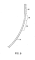
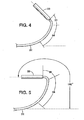
FIGS. 3-5 are representative illustrations of the degree of deflection of the distal regions of the catheter under the influence of increasing compressive loads; -
FIG. 6 is a longitudinal section of the handle portion of the catheter as seen along the line 6-6 ofFIG. 1 ; and -
FIGS. 7-9 are diagrammatic illustrations of an embodiment showing the sequence of operation in which the medical device can be recaptured before full deployment to enable repositioning or removal. - Specific embodiments of the present disclosure are now described with reference to the figures, wherein like reference numbers indicate identical or functionally similar elements. The terms "distal" and "proximal" are used in the following description with respect to a position or direction relative to the treating clinician. "Distal" or "distally" are a position distant from or in a direction away from the clinician. "Proximal" and "proximally" are a position near or in a direction toward the clinician.
- The drawings illustrate delivery catheters adapted to deliver relatively large diameter cardiovascular medical devices such as, for example, wireless pressure sensing devices and percutaneously placeable leadless pacing systems. It should be understood, however, that the principles of the invention may be incorporated in delivery catheters for delivering other, smaller devices such as stents and filters for distal embolic protection among others.
- As shown in
FIG. 1 , one embodiment of thedelivery catheter 10 has aproximal end 12 and adistal end 14. Ahandle 16 preferably is disposed at the proximal end for controlling operation of the catheter. The catheter has a catheter body that includes an outertubular sheath 18. An inner shaft 20 (FIG. 2 ) extends through the lumen ofouter sheath 18,sheath 18 andinner shaft 20 being movable longitudinally relative to each other. Ahousing 22 adapted to contain a medical device in a low profile configuration is attached to and extends distally from the distal end ofsheath 18.Device housing 22 defines achamber 24 having an opendistal port 23 that may be identifiable fluoroscopically by aradiopaque marker band 25 at the distal end of the housing. For ease of description, the catheter may be considered as having a linear axis 27 (FIG. 1 ) that extends along a direction coincident with the catheter when the catheter is straight, without bends.Linear axis 27 serves as a reference from which the arc of curvature of the deflected distal portions of the catheter may be measured.Device housing 22 may be considered to have its own linear axis that is aligned withcatheter axis 27 when the catheter is straight. -
Chamber 24 is adapted to contain any of a variety of medical devices to be deployed at a target location reachable by the navigable catheter. The diameter of the housing will depend on the dimensions of the medical device when in a collapsed, low profile configuration. In the event that the housing diameter is relatively large in relation to the outer sheath diameter, and the catheter introducer sheath with haemostatic valve (not shown) is large enough to accommodate the housing, the outer sheath of the catheter may be provided with a valve relief 55 (FIGS. 7-9 ) to take up the annular gap between the inside diameter of the introducer sheath and the outside diameter ofouter sheath 18. Valverelief 55 is slidable, but in a close fit aboutouter sheath 18, to minimize backbleeding between the valve relief and outer sheath. - By way of example,
chamber 24 may contain asensor assembly 26 that includes one ormore fixation members 28 affixed to asensor 30.Fixation member 28 may be self expendable from a low profile configuration to an expanded configuration for engagement with a vessel wall or other tissue to perform its function. For example, in an assembly adapted to sense blood pressure in a blood vessel, the fixation member may be adapted to engage the vessel wall with forces just sufficient to maintain the assembly in place without applying forces that may cause trauma to the vessel. By way of illustration such a sensor assembly is described in further detail inU. S. patent application S. N. 13/090,854 - As shown in
FIG. 1 ,outer sheath 18 of the catheter includes several serially attached segments including aproximal segment 32, anintermediate segment 34 and adistal segment 36.Housing 22 is attached to and extends distally from the distal end ofdistal segment 36 ofouter sheath 18. In the illustrated embodiments, for a delivery device adapted to contain and deliver a pressure sensing assembly or a pacing system, the outer diameter ofhousing 22 may be of the order of about 24 French (0.312 inch or 0.792 cm). Thesegments -
Proximal segment 32, which is the stiffest and longest of the segments, provides column strength for "pushability" and torsional rigidity to facilitate advancement of the catheter and torque transmission from the proximal end to the distal end of the catheter to facilitate steering. The proximal segment may be formed from stainless steel braided wire or from a polymer having longitudinal stiffening elements such as braided elements, coils or stiffening wires, if desired. Thehandle 16 is attached at the proximal end ofproximal segment 32. For a catheter intended to enter a patient's groin area and deploy a device in the pulmonary artery,proximal segment 32 may be of the order of about 100 centimeters in length and may be formed, for example, from a 72 Shore D medical grade plastic resin such as polyether block amide copolymer sold under the trademark PEBAX 7233. The outer diameter of the proximal, intermediate and distal segments may be of the order of about 0.170 inch (0.432 cm) with a wall thickness of the order of about 0.013 inches (0.033 cm) with an inner diameter of about 0.144 inch (0.366 cm).Proximal segment 32 may include an inner braided or other reinforcement should that be desired to enhance stiffness or torque transmission. It may be noted that, in the illustrative embodiments,housing 22 is larger in diameter than the body of the catheter proximal of the housing. This is a function of the collapsed diameter of the medical device to be delivered. While with such larger diameter devices the initial percutaneous access requires passing the housing through the punctured skin and subcutaneous tissue, once the housing has been placed in the blood vessel, such as the femoral artery, then the catheter can be advanced with relatively little resistance. -
Distal segment 36 is the shortest and most flexible of the catheter segments. It may be of the order of about three centimeters long and formed from more flexible, relatively soft 35 Shore D medical grade plastic resin such as polyether block amide copolymer sold under the trademark PEBAX 3533. The distal segment preferably includes a flexible braid as reinforcement.Intermediate segment 34 may be approximately ten centimeters long and has stiffness in between that of proximal anddistal segments proximal segment 32 to flexibledistal segment 36. It may be formed, for example, from a 40 Shore D medical grade plastic resin such as polyether block amide copolymer sold under the trademark PEBAX 4033. The segments may be joined end-to-end by any of a variety of techniques familiar to those skilled in the art such as, for example, adhesive, heat or ultrasonic bonding. -
Tubular device housing 22 may be larger in diameter thanouter sheath 18 and is attached to the distale end of flexibledistal segment 36 in an overlapping joint 38 to define adistally facing shelf 40 within the proximal portion ofhousing 22. Adhesive bonding or other suitable methods known to those skilled in the art may be used to join the housing and distal segment.Housing 22 is constructed to retain the medical device in a low profile configuration and may be made from any material suitable for that purpose.Housing 22 should be adapted to slide easily over the low profile medical device to expose and release the medical device. -
Inner shaft 20 extends through the lumen of and may be longer thanouter sheath 18 by an amount sufficient to permit operation as described bellow.Inner shaft 20 may be formed in one of a number of constructions to provide the requisite tensile strength to bendouter sheath 18 and to also provide compression strength to holdmedical device 26 in position whileouter sheath 18 is withdrawn during deployment. The inner shaft may be a solid or tubular structure, metallic or polymeric, or a combination of both and may have reinforcing elements such as braided or unbraided wires embedded in or attached as part of the inner shaft. The reinforcing elements, if used, may be incorporated in a manner that will bias the direction in which thecatheter 10 will bend to provide a predictive direction of articulation when the inner shaft is tensioned. Such biasing elements also may be incorporated into theouter sheath 18 for the same purpose. - An
abutment 42 is firmly secured to the distal end ofinner shaft 20, as by adhesive, welding or other suitable means and is contained slidably withinchamber 24 of thehousing 22.Abutment 42 preferably is radiopaque or is provided with a radiopaque marker to enhance its visibility under fluoroscopy and provide an indication of the location of the proximal end of the chamber and medical device.Abutment 42 may be disc-shaped and has adistal face 44 that defines the proximal end of thechamber 24.Abutment 42 may be of a metal or rigid polymeric material and has aproximal face 46 that engages withshelf 40 to limit proximal movement ofabutment 42 within the catheter. - When
abutment 42 andshelf 40 are engaged, tension applied toinner shaft 20 is transmitted to a longitudinally compressive force insheath 18. Longitudinal compression ofouter sheath 18 causessegments distal segment 36, a lesser degree of bending occurring in the intermediate,transition segment 34 and the least degree of bending occurring inproximal segment 32 as suggested inFIGS. 3-5 . The degree of articulation of the catheter is controllable by varying the degree of tension applied toinner shaft 20. When the tension on the inner shaft is released, the catheter will relax and will tend to straighten under the influence of the resilience of the catheter components to the extent permitted by the body passageway through which the catheter was navigated into the deployment position. To deploy a medical device, tension is applied toouter sheath 18 to retract the sheath and housing proximally with respect toinner shaft 20 andabutment 42 to expose and release a device contained inchamber 24. Thus, the arrangement of theouter sheath 18,inner shaft 20 andabutment 42 enable deflection of the catheter tip and deployment of the medical device by a single, dual-function mechanism. -
Delivery catheter 10 incorporates a construction that has relatively few components and is relatively easy to make. In contrast to steerable catheters in which one or more pull wires are attached eccentrically to the distal end of the catheter, the present invention avoids the need for a separate pull wire and does not require such a pull wire to be attached to the distal end of the catheter. Additionally, when assembling the delivery catheter it is not necessary to take care to precisely attach the inner shaft to an eccentric location to assure that the outer sheath will deflect in a particular direction. While the connection ofinner shaft 20 toabutment 42 may be eccentrically located, that is not necessary to the functioning of the invention. Tensioning theinner shaft 20 to longitudinally compress theouter sheath 18 will cause the sheath to articulate as described above. If it is desired to provide a predetermined bias to the direction in which the outer sheath will bend, that may be achieved by reinforcing or stiffening selected eccentric portions of the sheath to provide the desired bias. Additionally variations in wall thickness of selected regions of the outer sheath, particularly in the distal section, may be employed for that purpose. Regardless of the direction of bending taken byouter sheath 18,catheter 10 can be aimed by rotating the catheter to the desired angular orientation.Outer sheath 18 is constructed to provide torsional rigidity to facilitate transmission of rotation from the catheterproximal end 12 to the catheterdistal end 14. - The invention enables a substantial degree of articulation.
FIGS. 3-5 illustrate the relative articulation of the portions of the catheter under progressively increasing compressive load imposed onouter sheath 18 by the tensionedinner shaft 20 andabutment 42.FIG. 3 shows the degree of curvature when a relatively low level of tension is applied to theinner shaft 20.FIG. 4 shows the configuration with an increased level of tension andFIG. 5 shows the configuration with a further increased level of tension.Housing 22 is not subjected to the compressive load imposed onouter sheath 18 and remains in its straight tubular shape throughout the compressive loading on the sheath. As the compressive load increases it can be seen thathousing 22 is progressively oriented at an increasing angle tolinear axis 27. As seen inFIG. 5 ,housing 22 has been reoriented through an angle of about 180 degrees relative tolinear axis 27. Thus, as shown, to the extent thatproximal segment 32 may be curved away from the linear axis, it has the largest radius and least amount of curvature,intermediate segment 34 displays a greater degree of curvature with a smaller radius anddistal segment 36 undergoes the greatest degree of curvature with the smallest radius. By varying the tension oninner shaft 20 and by rotating the catheter, the orientation ofhousing 22 can be controllably directed to facilitate steering the delivery catheter along the selected path to the deployment site. - After
delivery catheter 10 has been advanced to placehousing 22 at the intended target site and the clinician has determined that the medical device can be released, the position ofinner shaft 20 is maintained whileouter sheath 18 andhousing 22 are retracted proximally to progressively exposemedical device 26 and permit it to self-expand as it deploys within the vessel (seeFIG. 7 , discussed below). During release, the position of the medical device in the patient is maintained by engagement of its proximal end with the abutment 42 (FIG. 2 ). As the retraction ofsheath 18 is initiated the tension oninner shaft 18 is released and the catheter is free to assume a relaxed configuration defined by the path through which the catheter was advanced to reach the target site. -
Handle 16 atproximal end 12 controls the operation of the catheter. As shown inFIG. 6 handle 16 includes ahousing 48 that contains aslide 50 for longitudinal sliding movement therewithin.Slide 50 has a portion that extends transversely through alongitudinal slot 54 inhandle housing 48 and defines an externallyaccessible button 52 that may be manipulated by the clinician to moveslide 50 forward or rearward.Slide 50 is attached near the proximal end ofinner shaft 20 and the proximal end ofouter sheath 18 is secured tohousing 48. The components are arranged so that the button and slide will have a neutral position midway alongslot 54 in whichinner shaft 20 is not tensioned andabutment 42 is in its proximal position againstshelf 40. Thus, in this arrangement the inner shaft may be tensioned to deflect the distal end ofcatheter 10 by retractingslide 50 relative to handlehousing 48 in a proximal direction from the neutral position. Retracting handlehousing 48 relative to theslide 50 in a proximal direction will maintain the position ofmedical device 26 in the patient's anatomy while causingsheath 18 andhousing 22 to be withdrawn to deploy the medical device. - A reverse arrangement (not shown) may be employed in which
inner shaft 20 is connected tohousing 48 proximally ofslot 54 and the proximal end ofouter sheath 18 is connected to slide 50 such that it is axially movable withinhousing 48, resulting in a reversed mode of operation for tensioning and sheath retraction. For example, in the reverse arrangement, retractingslide 50 relative tohousing 48 in a proximal direction from the neutral position will maintain the position ofmedical device 26 in the patient's anatomy while causingsheath 18 andhousing 22 to be withdrawn to deploy the medical device. -
Handle 16 may include a Tuohy-Borst type fitting 56, shown schematically inFIG. 6 and discussed in further detail below, and aside port 57 that communicates with the lumen ofinner shaft 20 to enable fluid to pass through the catheter, as for flushing or other purposes. As illustrated inFIG. 6 ,tube 58 is fixed withinhousing 48 and receives the proximal end of hollowinner shaft 20 to form a sliding seal therebetween. Thus,side port 57 fluidly communicates with the lumen ofinner shaft 20 via the interior oftube 58 andchamber 59 ofhandle housing 48. To also flush the lumen ofouter sheath 18 anddevice housing 22, one or more ports (not shown) may be provided through the wall ofinner shaft 20 generally midway along the length of the inner shaft. In this embodiment, liquid injected intoside port 57 will flow through the lumen of hollowinner shaft 20 and also through the flush port inshaft 20 into the lumen ofouter sheath 18. Air can thus be forced out of the distal end ofinner shaft 20 and from both ends ofouter sheath 18. -
FIGS. 7-9 illustrate, diagrammatically, a modified embodiment of the invention in which partially deployedmedical device 26 can be recaptured intohousing 22 if it is determined that the implantable device was not deployed properly or in the correct position. Upon recapture,medical device 26 can be repositioned and redeployed or removed from the patient. In this embodiment a suture thread orwire tether 48 extends through thedelivery catheter 10, preferably through the lumen of a tubularinner shaft 20, the tether being doubled to define abight 50 at its distal end and a pair offree tails 52 that protrude from a fitting 56 at the proximal end ofhandle 16.Tether 48 is passed through an aperture in the medical device so thatbight 50 is attached thereto. An aperture als is formed inabutment 42 to permit doubledtether 48 to pass through the abutment intochamber 24. The fitting 56 is of the type that can be adjusted to clamp or release thefree tails 52, such as a Tuohy-Borst type of device having that can be twisted to grip or release the tether with a compressible element. Whencatheter 10 is ready to delivermedical device 26, the device will be contained in a low profile configuration inhousing 22 withtether 48 extending from an aperture in the proximal end of the device and with fitting 56 tightened abouttails 52 oftether 48 to lock them in place. After the catheter has been navigated to locatehousing 22 at the intended deployment site, the slide in the handle is operated to withdraw the sheath to allow the medical device to engage the vessel or other target tissue (FIG. 8 ). At this juncture the clinician may observe, fluoroscopically, the position and orientation of the device. If the clinician is satisfied with the device placement, fitting 56 is opened to release the grip ontether 48 and one of thetails 52 can be pulled to withdraw and unthread the tether from engagement with the aperture of medical device (FIG. 9 ). However, if the placement is not found to be satisfactory, thensheath 18 andcapsule 22 can be advanced distally overtether 48 to recapturedevice 26 inchamber 24. The recapture movement will transformmedical device 26 back to the low profile configuration by compressingfixation members 28 as they are drawn intochamber 24. The catheter then can be repositioned and the device redeployed or the entire assembly may be removed from the patient. - From the foregoing it will be appreciated that the invention provides a delivery catheter for a medical device that is of simplified construction with relatively few components and which is easily constructed. The catheter avoids the need for a separate guide wire to navigate the catheter or a separate pull wire to control the deflection of the distal end of the catheter. The single mechanism by which the catheter is operated controls both functions of tip deflection and deployment of the medical device. It should be understood that the foregoing description of the invention is intended only as illustrative and that other embodiments, modifications and equivalents may be apparent without departing from the invention, as defined in the claims.
Claims (15)
- A steerable catheter (10) for delivering and deploying a medical device (26) comprising:an elongate tubular outer sheath (18) having proximal and distal ends and a linear axis (27);a housing (22) mounted to the distal end of the sheath, the housing defining a chamber (24) adapted to contain the medical device, the housing having an open distal port (23) at its distal end;an inner shaft (20) extending through the sheath, the inner shaft being relatively inextensible under tension;an abutment (42) secured to the distal end of the inner shaft, the abutment being disposed in the chamber and defining the proximal end of the chamber, the inner shaft and abutment being movable longitudinally with respect to the sheath and housing;the outer sheath (18) having a shelf (40) adjacent the proximal region of the housing and proximal of the abutment, the shelf being adapted to be engaged by a proximally facing surface of the abutment to apply a compressive force to the outer sheath in response to tensioning of the inner shaft (20);the outer sheath (18) being sufficiently torsionally rigid to transmit, controllably, rotation applied at the proximal end to the distal end;the outer sheath (18) being constructed to bend longitudinally away from the linear axis (27) under a compressive load applied by the abutment (42) against the shelf (40), the degree of bending corresponding to the degree of compression applied to the sheath; andthe outer sheath (18) being retractable relative to the abutment (42) whereby a medical device (26) contained in the chamber (24) may be at least partially deployed at a selected location by retracting the outer sheath relative to the abutment.
- The catheter (10) as defined in claim 1 wherein the outer sheath (18) is constructed to have increasing flexibility in a distal direction.
- The catheter (10) as defined in claim 2 wherein the outer sheath (18) is formed from a plurality of serially connected segments (32, 34, 36), the most distal of the segments (36) being the most flexible and exhibiting the greatest degree of longitudinal bending as the sheath is compressed.
- The catheter as defined in claim 3 wherein the outer sheath (18) has at least three segments (32, 34, 36) including a proximal segment (32), a shorter intermediate segment (34) and a still shorter distal segment (36), the housing (22) being relatively inflexible and extending distally from the distal end of the distal segment (36).
- The catheter (10) as defined in claim 2 wherein the outer sheath (18) is bendable in response to tensioning of the inner shaft (20) to define an angle of at least about 90 degrees between an axis of the housing (22) and the linear axis (27).
- The catheter as defined in claim 2 wherein the outer sheath (18) is bendable in response tensioning the inner shaft (20) to define an angle of at least about 180 degrees between an axis of the housing (22) and the linear axis (27).
- The catheter (10) as defined in claim 3 wherein the shelf (40) is defined by the distal end of the distal segment (36) of the sheath (18), the proximal end of the housing (22) being attached to and about the distal end of the distal segment with the shelf (40) being disposed within the housing (22).
- The catheter (10) as defined in claim 7 wherein the shelf (40) is annular and the abutment (42) is in the form of a disc having a diameter to abut the shelf.
- The catheter (10) as defined in claim 1 wherein the inner shaft (20) includes a lumen extending along its length, the abutment (42) having an aperture in communication with the lumen whereby a tether (48) can extend from a medical device (26) in the chamber (24) to the proximal end of the catheter.
- The catheter (10) as defined in claim 9 further comprising a clamp (56) at the proximal end of the catheter, the clamp being adapted to receive and releasably clamp the proximal end of the tether (48).
- The catheter (10) as defined in claim 1 wherein the abutment (42) is radiopaque to enable the location of the proximal end of the chamber (24) determined fluoroscopically when the chamber is loaded with the medical device (26).
- The catheter (10) as defined in claim 11 further comprising a radiopaque marker band (25) located at the distal end of the housing (22).
- The catheter (10) as defined in claim 1 further comprising:a handle (16) at the proximal end of catheter, the handle containing a slide (50) mounted for longitudinal movement, the slide being operable externally of the handle;the proximal end of the sheath (18) being attached to one of the handle or the slide; andthe proximal end of the inner shaft (20) being attached to the other of the handle or the slide.
- The catheter (10) as defined in claim 13 further comprising a side port (57) mounted to the handle (16) in communication with the inner shaft (20) to enable fluid communication between the proximal and distal ends of the catheter.
- The catheter (10) as defined in claim 1 wherein the catheter has a length sufficient to reach the pulmonary artery.
Applications Claiming Priority (2)
| Application Number | Priority Date | Filing Date | Title |
|---|---|---|---|
| US13/176,193 US8926588B2 (en) | 2011-07-05 | 2011-07-05 | Steerable delivery catheter |
| PCT/US2012/043575 WO2013006282A1 (en) | 2011-07-05 | 2012-06-21 | Steerable delivery catheter |
Publications (2)
| Publication Number | Publication Date |
|---|---|
| EP2729093A1 EP2729093A1 (en) | 2014-05-14 |
| EP2729093B1 true EP2729093B1 (en) | 2015-10-21 |
Family
ID=46457086
Family Applications (1)
| Application Number | Title | Priority Date | Filing Date |
|---|---|---|---|
| EP12731870.7A Active EP2729093B1 (en) | 2011-07-05 | 2012-06-21 | Steerable delivery catheter |
Country Status (6)
| Country | Link |
|---|---|
| US (1) | US8926588B2 (en) |
| EP (1) | EP2729093B1 (en) |
| JP (1) | JP5830794B2 (en) |
| CN (1) | CN103635160B (en) |
| BR (1) | BR112013033875A2 (en) |
| WO (1) | WO2013006282A1 (en) |
Cited By (14)
| Publication number | Priority date | Publication date | Assignee | Title |
|---|---|---|---|---|
| US10856984B2 (en) | 2017-08-25 | 2020-12-08 | Neovasc Tiara Inc. | Sequentially deployed transcatheter mitral valve prosthesis |
| US10940001B2 (en) | 2012-05-30 | 2021-03-09 | Neovasc Tiara Inc. | Methods and apparatus for loading a prosthesis onto a delivery system |
| US11311376B2 (en) | 2019-06-20 | 2022-04-26 | Neovase Tiara Inc. | Low profile prosthetic mitral valve |
| US11357622B2 (en) | 2016-01-29 | 2022-06-14 | Neovase Tiara Inc. | Prosthetic valve for avoiding obstruction of outflow |
| US11389291B2 (en) | 2013-04-04 | 2022-07-19 | Neovase Tiara Inc. | Methods and apparatus for delivering a prosthetic valve to a beating heart |
| US11413139B2 (en) | 2011-11-23 | 2022-08-16 | Neovasc Tiara Inc. | Sequentially deployed transcatheter mitral valve prosthesis |
| US11419720B2 (en) | 2010-05-05 | 2022-08-23 | Neovasc Tiara Inc. | Transcatheter mitral valve prosthesis |
| US11464631B2 (en) | 2016-11-21 | 2022-10-11 | Neovasc Tiara Inc. | Methods and systems for rapid retraction of a transcatheter heart valve delivery system |
| US11491006B2 (en) | 2019-04-10 | 2022-11-08 | Neovasc Tiara Inc. | Prosthetic valve with natural blood flow |
| US11497602B2 (en) | 2012-02-14 | 2022-11-15 | Neovasc Tiara Inc. | Methods and apparatus for engaging a valve prosthesis with tissue |
| US11602429B2 (en) | 2019-04-01 | 2023-03-14 | Neovasc Tiara Inc. | Controllably deployable prosthetic valve |
| DE102021132097A1 (en) | 2021-12-06 | 2023-06-07 | Optimed Medizinische Instrumente Gmbh | Hand unit for delivering and releasing an implant |
| US11737872B2 (en) | 2018-11-08 | 2023-08-29 | Neovasc Tiara Inc. | Ventricular deployment of a transcatheter mitral valve prosthesis |
| US11779742B2 (en) | 2019-05-20 | 2023-10-10 | Neovasc Tiara Inc. | Introducer with hemostasis mechanism |
Families Citing this family (83)
| Publication number | Priority date | Publication date | Assignee | Title |
|---|---|---|---|---|
| US9572481B2 (en) | 2011-05-13 | 2017-02-21 | Intuitive Surgical Operations, Inc. | Medical system with multiple operating modes for steering a medical instrument through linked body passages |
| US20140052109A1 (en) * | 2012-08-19 | 2014-02-20 | Diros Technology Inc. | Steerable Multifunction Catheter Probe with High Guidability and Reversible Rigidity |
| US9233225B2 (en) | 2012-11-10 | 2016-01-12 | Curvo Medical, Inc. | Coaxial bi-directional catheter |
| ES2931210T3 (en) * | 2012-11-21 | 2022-12-27 | Edwards Lifesciences Corp | Retention Mechanisms for Prosthetic Heart Valves |
| ITPD20130020A1 (en) * | 2013-01-30 | 2014-07-31 | Gioachino Coppi | VARIABLE BEND CATHETER |
| US10071243B2 (en) | 2013-07-31 | 2018-09-11 | Medtronic, Inc. | Fixation for implantable medical devices |
| US9393427B2 (en) | 2013-08-16 | 2016-07-19 | Cardiac Pacemakers, Inc. | Leadless cardiac pacemaker with delivery and/or retrieval features |
| US10842993B2 (en) | 2013-08-16 | 2020-11-24 | Cardiac Pacemakers, Inc. | Leadless cardiac pacing devices |
| US9480850B2 (en) | 2013-08-16 | 2016-11-01 | Cardiac Pacemakers, Inc. | Leadless cardiac pacemaker and retrieval device |
| US9492674B2 (en) | 2013-08-16 | 2016-11-15 | Cardiac Pacemakers, Inc. | Leadless cardiac pacemaker with delivery and/or retrieval features |
| EP3338856B1 (en) | 2013-08-16 | 2021-08-04 | Cardiac Pacemakers, Inc. | Delivery devices for leadless cardiac devices |
| ES2652306T3 (en) | 2013-08-16 | 2018-02-01 | Cardiac Pacemakers, Inc. | Lead-free cardiac stimulation device |
| US10722723B2 (en) * | 2013-08-16 | 2020-07-28 | Cardiac Pacemakers, Inc. | Delivery devices and methods for leadless cardiac devices |
| CN105744987B (en) | 2013-08-16 | 2019-01-15 | 心脏起搏器股份公司 | Leadless cardiac pacemaker and fetch equipment |
| US20150119847A1 (en) * | 2013-10-29 | 2015-04-30 | Medwerks, Llc | Atraumatic Guidewire And Method Of Use |
| US9572666B2 (en) | 2014-03-17 | 2017-02-21 | Evalve, Inc. | Mitral valve fixation device removal devices and methods |
| WO2015168155A1 (en) | 2014-04-29 | 2015-11-05 | Cardiac Pacemakers, Inc. | Leadless cardiac pacemaker with retrieval features |
| US10080887B2 (en) | 2014-04-29 | 2018-09-25 | Cardiac Pacemakers, Inc. | Leadless cardiac pacing devices including tissue engagement verification |
| US10441777B2 (en) | 2014-09-09 | 2019-10-15 | Pacesetter, Inc. | Implantable medical device having restrained tether device |
| US10716931B2 (en) | 2014-09-09 | 2020-07-21 | Pacesetter, Inc. | Systems and methods for implanting a medical device |
| EP3209225B1 (en) | 2014-10-22 | 2021-09-22 | Cardiac Pacemakers, Inc. | Delivery devices for leadless cardiac devices |
| ES2824798T3 (en) | 2014-10-22 | 2021-05-13 | Cardiac Pacemakers Inc | Implantation Devices for Cordless Heart Devices |
| US20160206872A1 (en) * | 2015-01-16 | 2016-07-21 | Medtronic, Inc. | Interventional medical tools and assemblies |
| US9937322B2 (en) | 2015-04-23 | 2018-04-10 | Medtronic, Inc. | Assemblies and methods for deflectable shaft catheters |
| US9867964B2 (en) | 2015-04-23 | 2018-01-16 | Medtronic, Inc. | Interventional medical systems, assemblies, and construction methods |
| CN107592821B (en) * | 2015-05-13 | 2021-11-23 | 美敦力公司 | Securing an implantable medical device in place while reducing perforation |
| WO2016183417A1 (en) | 2015-05-13 | 2016-11-17 | Medtronic, Inc. | Securing an implantable medical device in position while reducing perforations |
| US10376673B2 (en) | 2015-06-19 | 2019-08-13 | Evalve, Inc. | Catheter guiding system and methods |
| US10525256B2 (en) * | 2015-07-29 | 2020-01-07 | Medtronic, Inc. | Interventional medical systems, catheters, and methods |
| US10080862B2 (en) * | 2015-08-14 | 2018-09-25 | Medtronic, Inc. | Tubular bodies for medical delivery devices and related manufacturing methods |
| CN108348759B (en) * | 2015-11-20 | 2021-08-17 | 心脏起搏器股份公司 | Delivery devices and methods for leadless cardiac devices |
| EP3377173A1 (en) | 2015-11-20 | 2018-09-26 | Cardiac Pacemakers, Inc. | Delivery devices and methods for leadless cardiac devices |
| CA3010298A1 (en) * | 2015-12-30 | 2017-07-06 | Pipeline Medical Technologies, Inc. | Mitral leaflet tethering |
| US10099050B2 (en) | 2016-01-21 | 2018-10-16 | Medtronic, Inc. | Interventional medical devices, device systems, and fixation components thereof |
| US10463853B2 (en) | 2016-01-21 | 2019-11-05 | Medtronic, Inc. | Interventional medical systems |
| US20210212824A1 (en) * | 2016-03-08 | 2021-07-15 | Dura Llc | Heart valve leaflet replacement devices and multi-stage, multi-lumen heart valve delivery systems and method for use |
| US10278852B2 (en) * | 2016-03-10 | 2019-05-07 | Medtronic Vascular, Inc. | Steerable catheter with multiple bending radii via a steering mechanism with telescoping tubular components |
| US10736632B2 (en) | 2016-07-06 | 2020-08-11 | Evalve, Inc. | Methods and devices for valve clip excision |
| US10639151B2 (en) | 2016-07-29 | 2020-05-05 | Cephea Valve Technologies, Inc. | Threaded coil |
| CN207590809U (en) * | 2016-07-29 | 2018-07-10 | 上海沃比医疗科技有限公司 | Implantation material transport system |
| US10661052B2 (en) | 2016-07-29 | 2020-05-26 | Cephea Valve Technologies, Inc. | Intravascular device delivery sheath |
| US11324495B2 (en) | 2016-07-29 | 2022-05-10 | Cephea Valve Technologies, Inc. | Systems and methods for delivering an intravascular device to the mitral annulus |
| US10646689B2 (en) | 2016-07-29 | 2020-05-12 | Cephea Valve Technologies, Inc. | Mechanical interlock for catheters |
| US10974027B2 (en) | 2016-07-29 | 2021-04-13 | Cephea Valve Technologies, Inc. | Combination steerable catheter and systems |
| US10933216B2 (en) * | 2016-08-29 | 2021-03-02 | Cephea Valve Technologies, Inc. | Multilumen catheter |
| US10751485B2 (en) | 2016-08-29 | 2020-08-25 | Cephea Valve Technologies, Inc. | Methods, systems, and devices for sealing and flushing a delivery system |
| US11109967B2 (en) | 2016-08-29 | 2021-09-07 | Cephea Valve Technologies, Inc. | Systems and methods for loading and deploying an intravascular device |
| US11045315B2 (en) | 2016-08-29 | 2021-06-29 | Cephea Valve Technologies, Inc. | Methods of steering and delivery of intravascular devices |
| US10874512B2 (en) | 2016-10-05 | 2020-12-29 | Cephea Valve Technologies, Inc. | System and methods for delivering and deploying an artificial heart valve within the mitral annulus |
| US11071564B2 (en) | 2016-10-05 | 2021-07-27 | Evalve, Inc. | Cardiac valve cutting device |
| US11198013B2 (en) | 2016-11-21 | 2021-12-14 | Cardiac Pacemakers, Inc. | Catheter and leadless cardiac devices including electrical pathway barrier |
| EP3541460B1 (en) * | 2016-11-21 | 2020-12-23 | Cardiac Pacemakers, Inc. | Delivery devices and wall apposition sensing |
| WO2018098210A1 (en) | 2016-11-22 | 2018-05-31 | Synecor Llc | Guidewireless transseptal delivery system for therapeutic devices of the mitral valve |
| US10485981B2 (en) | 2016-12-27 | 2019-11-26 | Cardiac Pacemakers, Inc. | Fixation methods for leadless cardiac devices |
| US10722684B2 (en) | 2016-12-27 | 2020-07-28 | Cardiac Pacemakers, Inc. | Leadless delivery catheter with conductive pathway |
| US10806931B2 (en) | 2016-12-27 | 2020-10-20 | Cardiac Pacemakers, Inc. | Delivery devices and methods for leadless cardiac devices |
| WO2018136203A1 (en) | 2016-12-27 | 2018-07-26 | Cardiac Pacemakers, Inc. | Delivery devices and methods for leadless cardiac devices |
| US11083580B2 (en) | 2016-12-30 | 2021-08-10 | Pipeline Medical Technologies, Inc. | Method of securing a leaflet anchor to a mitral valve leaflet |
| US9877833B1 (en) | 2016-12-30 | 2018-01-30 | Pipeline Medical Technologies, Inc. | Method and apparatus for transvascular implantation of neo chordae tendinae |
| US10925731B2 (en) | 2016-12-30 | 2021-02-23 | Pipeline Medical Technologies, Inc. | Method and apparatus for transvascular implantation of neo chordae tendinae |
| CN108261256A (en) * | 2016-12-31 | 2018-07-10 | 先健科技(深圳)有限公司 | Conveying device and transport system |
| JP6735427B2 (en) | 2017-01-26 | 2020-08-05 | カーディアック ペースメイカーズ, インコーポレイテッド | Delivery device and delivery method for leadless heart device |
| EP3592418B1 (en) | 2017-03-10 | 2023-08-23 | Cardiac Pacemakers, Inc. | Fixation for leadless cardiac devices |
| US10737092B2 (en) | 2017-03-30 | 2020-08-11 | Cardiac Pacemakers, Inc. | Delivery devices and methods for leadless cardiac devices |
| US11577085B2 (en) | 2017-08-03 | 2023-02-14 | Cardiac Pacemakers, Inc. | Delivery devices and methods for leadless cardiac devices |
| WO2019055154A2 (en) | 2017-08-06 | 2019-03-21 | Synecor Llc | Systems and methods for transseptal delivery of therapeutic devices of the heart |
| MX2021002377A (en) * | 2018-08-29 | 2021-07-21 | Ernesto Molmenti | Knot-tying device for surgical sutures. |
| CN110947096B (en) * | 2018-09-27 | 2021-09-03 | 创领心律管理医疗器械(上海)有限公司 | Cardiac pacing system and pacemaker fixing device |
| US10894144B2 (en) * | 2018-10-16 | 2021-01-19 | Pacesetter, Inc. | Apparatus and method for sensor deployment and fixation |
| US11724068B2 (en) | 2018-11-16 | 2023-08-15 | Cephea Valve Technologies, Inc. | Intravascular delivery system |
| AU2019397490A1 (en) | 2018-12-12 | 2021-07-29 | Pipeline Medical Technologies, Inc. | Method and apparatus for mitral valve chord repair |
| US11065438B2 (en) | 2019-02-07 | 2021-07-20 | Synecor Llc | Systems and methods for transseptal delivery of percutaneous ventricular assist devices and other non-guidewire based transvascular therapeutic devices |
| EP3938021A1 (en) * | 2019-03-15 | 2022-01-19 | BIOTRONIK SE & Co. KG | Catheter device for implanting a medical device |
| US11759632B2 (en) | 2019-03-28 | 2023-09-19 | Medtronic, Inc. | Fixation components for implantable medical devices |
| WO2020205397A1 (en) | 2019-03-29 | 2020-10-08 | Cardiac Pacemakers, Inc. | Systems and methods for treating cardiac arrhythmias |
| CN113660977A (en) | 2019-03-29 | 2021-11-16 | 心脏起搏器股份公司 | System and method for treating cardiac arrhythmias |
| WO2020263742A1 (en) * | 2019-06-24 | 2020-12-30 | Medtronic, Inc. | Catheter handle with torque mechanism and valve relief component |
| US11524143B2 (en) | 2019-07-15 | 2022-12-13 | Medtronic, Inc. | Catheter with distal and proximal fixation members |
| US11524139B2 (en) | 2019-07-15 | 2022-12-13 | Medtronic, Inc. | Catheter with active return curve |
| JP2022547306A (en) | 2019-09-11 | 2022-11-11 | カーディアック ペースメイカーズ, インコーポレイテッド | Devices and systems for implanting and/or withdrawing leadless cardiac pacing devices using helical fixation |
| EP4028117A1 (en) | 2019-09-11 | 2022-07-20 | Cardiac Pacemakers, Inc. | Tools and systems for implanting and/or retrieving a leadless cardiac pacing device with helix fixation |
| US11872357B2 (en) | 2020-11-09 | 2024-01-16 | Agile Devices, Inc. | Devices for steering catheters |
| US20220296856A1 (en) * | 2021-03-16 | 2022-09-22 | Atricure, Inc. | Delivery devices and related methods |
Family Cites Families (16)
| Publication number | Priority date | Publication date | Assignee | Title |
|---|---|---|---|---|
| US2007626A (en) | 1933-04-14 | 1935-07-09 | Vadsco Salcs Corp | Capsule applicator |
| US3334629A (en) | 1964-11-09 | 1967-08-08 | Bertram D Cohn | Occlusive device for inferior vena cava |
| US4588395A (en) | 1978-03-10 | 1986-05-13 | Lemelson Jerome H | Catheter and method |
| US4512338A (en) | 1983-01-25 | 1985-04-23 | Balko Alexander B | Process for restoring patency to body vessels |
| US5372587A (en) * | 1989-01-09 | 1994-12-13 | Pilot Cariovascular Systems, Inc. | Steerable medical device |
| US5147379A (en) | 1990-11-26 | 1992-09-15 | Louisiana State University And Agricultural And Mechanical College | Insertion instrument for vena cava filter |
| US5397321A (en) * | 1993-07-30 | 1995-03-14 | Ep Technologies, Inc. | Variable curve electrophysiology catheter |
| FR2718345B1 (en) | 1994-04-11 | 1997-04-04 | Braun Celsa Sa | Handle for controlled relative sliding of a sheath and a rod and apparatus for implanting a medical device, such as a filter, using such a handle. |
| US5743874A (en) * | 1994-08-29 | 1998-04-28 | Fischell; Robert E. | Integrated catheter for balloon angioplasty and stent delivery |
| US5674271A (en) * | 1996-11-14 | 1997-10-07 | Denker; Stephen | Catheter with steerable stylet |
| US6818001B2 (en) * | 2000-04-05 | 2004-11-16 | Pathway Medical Technologies, Inc. | Intralumenal material removal systems and methods |
| US6773446B1 (en) | 2000-08-02 | 2004-08-10 | Cordis Corporation | Delivery apparatus for a self-expanding stent |
| US6607496B1 (en) | 2000-09-12 | 2003-08-19 | Medtronic, Inc. | Steerable stylet with enhanced torsional transfer strength |
| US7814912B2 (en) * | 2002-11-27 | 2010-10-19 | Pulmonx Corporation | Delivery methods and devices for implantable bronchial isolation devices |
| US7371248B2 (en) * | 2003-10-14 | 2008-05-13 | Medtronic Vascular, Inc. | Steerable distal protection guidewire and methods of use |
| FR2932080B1 (en) * | 2008-06-05 | 2010-08-13 | Perouse Lab | DEVICE FOR TREATING A BLOOD CIRCULATION CONDUIT |
-
2011
- 2011-07-05 US US13/176,193 patent/US8926588B2/en active Active
-
2012
- 2012-06-21 WO PCT/US2012/043575 patent/WO2013006282A1/en active Application Filing
- 2012-06-21 CN CN201280032326.1A patent/CN103635160B/en active Active
- 2012-06-21 BR BR112013033875A patent/BR112013033875A2/en not_active IP Right Cessation
- 2012-06-21 EP EP12731870.7A patent/EP2729093B1/en active Active
- 2012-06-21 JP JP2014518664A patent/JP5830794B2/en active Active
Cited By (18)
| Publication number | Priority date | Publication date | Assignee | Title |
|---|---|---|---|---|
| US11419720B2 (en) | 2010-05-05 | 2022-08-23 | Neovasc Tiara Inc. | Transcatheter mitral valve prosthesis |
| US11413139B2 (en) | 2011-11-23 | 2022-08-16 | Neovasc Tiara Inc. | Sequentially deployed transcatheter mitral valve prosthesis |
| US11497602B2 (en) | 2012-02-14 | 2022-11-15 | Neovasc Tiara Inc. | Methods and apparatus for engaging a valve prosthesis with tissue |
| US11617650B2 (en) | 2012-05-30 | 2023-04-04 | Neovasc Tiara Inc. | Methods and apparatus for loading a prosthesis onto a delivery system |
| US11389294B2 (en) | 2012-05-30 | 2022-07-19 | Neovasc Tiara Inc. | Methods and apparatus for loading a prosthesis onto a delivery system |
| US10940001B2 (en) | 2012-05-30 | 2021-03-09 | Neovasc Tiara Inc. | Methods and apparatus for loading a prosthesis onto a delivery system |
| US11389291B2 (en) | 2013-04-04 | 2022-07-19 | Neovase Tiara Inc. | Methods and apparatus for delivering a prosthetic valve to a beating heart |
| US11357622B2 (en) | 2016-01-29 | 2022-06-14 | Neovase Tiara Inc. | Prosthetic valve for avoiding obstruction of outflow |
| US11464631B2 (en) | 2016-11-21 | 2022-10-11 | Neovasc Tiara Inc. | Methods and systems for rapid retraction of a transcatheter heart valve delivery system |
| US10856984B2 (en) | 2017-08-25 | 2020-12-08 | Neovasc Tiara Inc. | Sequentially deployed transcatheter mitral valve prosthesis |
| US11793640B2 (en) | 2017-08-25 | 2023-10-24 | Neovasc Tiara Inc. | Sequentially deployed transcatheter mitral valve prosthesis |
| US11737872B2 (en) | 2018-11-08 | 2023-08-29 | Neovasc Tiara Inc. | Ventricular deployment of a transcatheter mitral valve prosthesis |
| US11602429B2 (en) | 2019-04-01 | 2023-03-14 | Neovasc Tiara Inc. | Controllably deployable prosthetic valve |
| US11491006B2 (en) | 2019-04-10 | 2022-11-08 | Neovasc Tiara Inc. | Prosthetic valve with natural blood flow |
| US11779742B2 (en) | 2019-05-20 | 2023-10-10 | Neovasc Tiara Inc. | Introducer with hemostasis mechanism |
| US11311376B2 (en) | 2019-06-20 | 2022-04-26 | Neovase Tiara Inc. | Low profile prosthetic mitral valve |
| US11931254B2 (en) | 2019-06-20 | 2024-03-19 | Neovasc Tiara Inc. | Low profile prosthetic mitral valve |
| DE102021132097A1 (en) | 2021-12-06 | 2023-06-07 | Optimed Medizinische Instrumente Gmbh | Hand unit for delivering and releasing an implant |
Also Published As
| Publication number | Publication date |
|---|---|
| US20130012925A1 (en) | 2013-01-10 |
| WO2013006282A1 (en) | 2013-01-10 |
| CN103635160B (en) | 2016-03-09 |
| CN103635160A (en) | 2014-03-12 |
| US8926588B2 (en) | 2015-01-06 |
| BR112013033875A2 (en) | 2017-02-07 |
| EP2729093A1 (en) | 2014-05-14 |
| JP2014520598A (en) | 2014-08-25 |
| JP5830794B2 (en) | 2015-12-09 |
Similar Documents
| Publication | Publication Date | Title |
|---|---|---|
| EP2729093B1 (en) | Steerable delivery catheter | |
| US7481793B2 (en) | Modular steerable sheath catheters | |
| US10569062B2 (en) | Low profile occlusion catheter | |
| US10780247B2 (en) | Catheter structure with improved support and related systems, methods, and devices | |
| EP3088034B1 (en) | Adjustable bent sheath tube | |
| US20050124977A1 (en) | Flexible polymer needle catheter | |
| US11446470B2 (en) | Catheter handle with torque mechanism and valve relief component | |
| US20160096002A1 (en) | Segmented Catheter Structure and Improved Catheter Tip and Related Systems, Methods, and Devices | |
| EP2244775B1 (en) | Deployment catheter and delivery system thereof | |
| US20220110645A1 (en) | Reentry catheter for crossing a vascular occlusion | |
| JP2008500090A (en) | Catheter device |
Legal Events
| Date | Code | Title | Description |
|---|---|---|---|
| PUAI | Public reference made under article 153(3) epc to a published international application that has entered the european phase |
Free format text: ORIGINAL CODE: 0009012 |
|
| 17P | Request for examination filed |
Effective date: 20140131 |
|
| AK | Designated contracting states |
Kind code of ref document: A1 Designated state(s): AL AT BE BG CH CY CZ DE DK EE ES FI FR GB GR HR HU IE IS IT LI LT LU LV MC MK MT NL NO PL PT RO RS SE SI SK SM TR |
|
| DAX | Request for extension of the european patent (deleted) | ||
| REG | Reference to a national code |
Ref country code: DE Ref legal event code: R079 Ref document number: 602012011800 Country of ref document: DE Free format text: PREVIOUS MAIN CLASS: A61F0002460000 Ipc: A61M0025010000 |
|
| RIC1 | Information provided on ipc code assigned before grant |
Ipc: A61F 2/966 20130101ALI20150420BHEP Ipc: A61N 1/372 20060101ALI20150420BHEP Ipc: A61F 2/46 20060101ALI20150420BHEP Ipc: A61F 2/01 20060101ALI20150420BHEP Ipc: A61F 2/24 20060101ALI20150420BHEP Ipc: A61B 17/22 20060101ALI20150420BHEP Ipc: A61B 5/0215 20060101ALI20150420BHEP Ipc: A61M 25/01 20060101AFI20150420BHEP Ipc: A61M 25/00 20060101ALI20150420BHEP |
|
| GRAP | Despatch of communication of intention to grant a patent |
Free format text: ORIGINAL CODE: EPIDOSNIGR1 |
|
| INTG | Intention to grant announced |
Effective date: 20150720 |
|
| GRAS | Grant fee paid |
Free format text: ORIGINAL CODE: EPIDOSNIGR3 |
|
| GRAA | (expected) grant |
Free format text: ORIGINAL CODE: 0009210 |
|
| AK | Designated contracting states |
Kind code of ref document: B1 Designated state(s): AL AT BE BG CH CY CZ DE DK EE ES FI FR GB GR HR HU IE IS IT LI LT LU LV MC MK MT NL NO PL PT RO RS SE SI SK SM TR |
|
| REG | Reference to a national code |
Ref country code: GB Ref legal event code: FG4D |
|
| REG | Reference to a national code |
Ref country code: CH Ref legal event code: EP |
|
| REG | Reference to a national code |
Ref country code: AT Ref legal event code: REF Ref document number: 756199 Country of ref document: AT Kind code of ref document: T Effective date: 20151115 |
|
| REG | Reference to a national code |
Ref country code: IE Ref legal event code: FG4D |
|
| REG | Reference to a national code |
Ref country code: DE Ref legal event code: R096 Ref document number: 602012011800 Country of ref document: DE |
|
| REG | Reference to a national code |
Ref country code: LT Ref legal event code: MG4D |
|
| REG | Reference to a national code |
Ref country code: NL Ref legal event code: FP |
|
| REG | Reference to a national code |
Ref country code: AT Ref legal event code: MK05 Ref document number: 756199 Country of ref document: AT Kind code of ref document: T Effective date: 20151021 |
|
| PG25 | Lapsed in a contracting state [announced via postgrant information from national office to epo] |
Ref country code: NO Free format text: LAPSE BECAUSE OF FAILURE TO SUBMIT A TRANSLATION OF THE DESCRIPTION OR TO PAY THE FEE WITHIN THE PRESCRIBED TIME-LIMIT Effective date: 20160121 Ref country code: ES Free format text: LAPSE BECAUSE OF FAILURE TO SUBMIT A TRANSLATION OF THE DESCRIPTION OR TO PAY THE FEE WITHIN THE PRESCRIBED TIME-LIMIT Effective date: 20151021 Ref country code: IS Free format text: LAPSE BECAUSE OF FAILURE TO SUBMIT A TRANSLATION OF THE DESCRIPTION OR TO PAY THE FEE WITHIN THE PRESCRIBED TIME-LIMIT Effective date: 20160221 Ref country code: IT Free format text: LAPSE BECAUSE OF FAILURE TO SUBMIT A TRANSLATION OF THE DESCRIPTION OR TO PAY THE FEE WITHIN THE PRESCRIBED TIME-LIMIT Effective date: 20151021 Ref country code: LT Free format text: LAPSE BECAUSE OF FAILURE TO SUBMIT A TRANSLATION OF THE DESCRIPTION OR TO PAY THE FEE WITHIN THE PRESCRIBED TIME-LIMIT Effective date: 20151021 Ref country code: HR Free format text: LAPSE BECAUSE OF FAILURE TO SUBMIT A TRANSLATION OF THE DESCRIPTION OR TO PAY THE FEE WITHIN THE PRESCRIBED TIME-LIMIT Effective date: 20151021 |
|
| PG25 | Lapsed in a contracting state [announced via postgrant information from national office to epo] |
Ref country code: GR Free format text: LAPSE BECAUSE OF FAILURE TO SUBMIT A TRANSLATION OF THE DESCRIPTION OR TO PAY THE FEE WITHIN THE PRESCRIBED TIME-LIMIT Effective date: 20160122 Ref country code: PT Free format text: LAPSE BECAUSE OF FAILURE TO SUBMIT A TRANSLATION OF THE DESCRIPTION OR TO PAY THE FEE WITHIN THE PRESCRIBED TIME-LIMIT Effective date: 20160222 Ref country code: RS Free format text: LAPSE BECAUSE OF FAILURE TO SUBMIT A TRANSLATION OF THE DESCRIPTION OR TO PAY THE FEE WITHIN THE PRESCRIBED TIME-LIMIT Effective date: 20151021 Ref country code: SE Free format text: LAPSE BECAUSE OF FAILURE TO SUBMIT A TRANSLATION OF THE DESCRIPTION OR TO PAY THE FEE WITHIN THE PRESCRIBED TIME-LIMIT Effective date: 20151021 Ref country code: FI Free format text: LAPSE BECAUSE OF FAILURE TO SUBMIT A TRANSLATION OF THE DESCRIPTION OR TO PAY THE FEE WITHIN THE PRESCRIBED TIME-LIMIT Effective date: 20151021 Ref country code: PL Free format text: LAPSE BECAUSE OF FAILURE TO SUBMIT A TRANSLATION OF THE DESCRIPTION OR TO PAY THE FEE WITHIN THE PRESCRIBED TIME-LIMIT Effective date: 20151021 Ref country code: AT Free format text: LAPSE BECAUSE OF FAILURE TO SUBMIT A TRANSLATION OF THE DESCRIPTION OR TO PAY THE FEE WITHIN THE PRESCRIBED TIME-LIMIT Effective date: 20151021 Ref country code: LV Free format text: LAPSE BECAUSE OF FAILURE TO SUBMIT A TRANSLATION OF THE DESCRIPTION OR TO PAY THE FEE WITHIN THE PRESCRIBED TIME-LIMIT Effective date: 20151021 |
|
| REG | Reference to a national code |
Ref country code: FR Ref legal event code: PLFP Year of fee payment: 5 |
|
| REG | Reference to a national code |
Ref country code: DE Ref legal event code: R097 Ref document number: 602012011800 Country of ref document: DE |
|
| PG25 | Lapsed in a contracting state [announced via postgrant information from national office to epo] |
Ref country code: CZ Free format text: LAPSE BECAUSE OF FAILURE TO SUBMIT A TRANSLATION OF THE DESCRIPTION OR TO PAY THE FEE WITHIN THE PRESCRIBED TIME-LIMIT Effective date: 20151021 |
|
| PLBE | No opposition filed within time limit |
Free format text: ORIGINAL CODE: 0009261 |
|
| STAA | Information on the status of an ep patent application or granted ep patent |
Free format text: STATUS: NO OPPOSITION FILED WITHIN TIME LIMIT |
|
| PG25 | Lapsed in a contracting state [announced via postgrant information from national office to epo] |
Ref country code: RO Free format text: LAPSE BECAUSE OF FAILURE TO SUBMIT A TRANSLATION OF THE DESCRIPTION OR TO PAY THE FEE WITHIN THE PRESCRIBED TIME-LIMIT Effective date: 20151021 Ref country code: SM Free format text: LAPSE BECAUSE OF FAILURE TO SUBMIT A TRANSLATION OF THE DESCRIPTION OR TO PAY THE FEE WITHIN THE PRESCRIBED TIME-LIMIT Effective date: 20151021 Ref country code: DK Free format text: LAPSE BECAUSE OF FAILURE TO SUBMIT A TRANSLATION OF THE DESCRIPTION OR TO PAY THE FEE WITHIN THE PRESCRIBED TIME-LIMIT Effective date: 20151021 Ref country code: EE Free format text: LAPSE BECAUSE OF FAILURE TO SUBMIT A TRANSLATION OF THE DESCRIPTION OR TO PAY THE FEE WITHIN THE PRESCRIBED TIME-LIMIT Effective date: 20151021 Ref country code: SK Free format text: LAPSE BECAUSE OF FAILURE TO SUBMIT A TRANSLATION OF THE DESCRIPTION OR TO PAY THE FEE WITHIN THE PRESCRIBED TIME-LIMIT Effective date: 20151021 |
|
| 26N | No opposition filed |
Effective date: 20160722 |
|
| PG25 | Lapsed in a contracting state [announced via postgrant information from national office to epo] |
Ref country code: SI Free format text: LAPSE BECAUSE OF FAILURE TO SUBMIT A TRANSLATION OF THE DESCRIPTION OR TO PAY THE FEE WITHIN THE PRESCRIBED TIME-LIMIT Effective date: 20151021 |
|
| PG25 | Lapsed in a contracting state [announced via postgrant information from national office to epo] |
Ref country code: BE Free format text: LAPSE BECAUSE OF FAILURE TO SUBMIT A TRANSLATION OF THE DESCRIPTION OR TO PAY THE FEE WITHIN THE PRESCRIBED TIME-LIMIT Effective date: 20151021 |
|
| PG25 | Lapsed in a contracting state [announced via postgrant information from national office to epo] |
Ref country code: MC Free format text: LAPSE BECAUSE OF FAILURE TO SUBMIT A TRANSLATION OF THE DESCRIPTION OR TO PAY THE FEE WITHIN THE PRESCRIBED TIME-LIMIT Effective date: 20151021 |
|
| REG | Reference to a national code |
Ref country code: CH Ref legal event code: PL |
|
| GBPC | Gb: european patent ceased through non-payment of renewal fee |
Effective date: 20160621 |
|
| PG25 | Lapsed in a contracting state [announced via postgrant information from national office to epo] |
Ref country code: CH Free format text: LAPSE BECAUSE OF NON-PAYMENT OF DUE FEES Effective date: 20160630 Ref country code: LI Free format text: LAPSE BECAUSE OF NON-PAYMENT OF DUE FEES Effective date: 20160630 |
|
| PG25 | Lapsed in a contracting state [announced via postgrant information from national office to epo] |
Ref country code: GB Free format text: LAPSE BECAUSE OF NON-PAYMENT OF DUE FEES Effective date: 20160621 |
|
| REG | Reference to a national code |
Ref country code: FR Ref legal event code: PLFP Year of fee payment: 6 |
|
| PG25 | Lapsed in a contracting state [announced via postgrant information from national office to epo] |
Ref country code: HU Free format text: LAPSE BECAUSE OF FAILURE TO SUBMIT A TRANSLATION OF THE DESCRIPTION OR TO PAY THE FEE WITHIN THE PRESCRIBED TIME-LIMIT; INVALID AB INITIO Effective date: 20120621 |
|
| REG | Reference to a national code |
Ref country code: FR Ref legal event code: PLFP Year of fee payment: 7 |
|
| PG25 | Lapsed in a contracting state [announced via postgrant information from national office to epo] |
Ref country code: MK Free format text: LAPSE BECAUSE OF FAILURE TO SUBMIT A TRANSLATION OF THE DESCRIPTION OR TO PAY THE FEE WITHIN THE PRESCRIBED TIME-LIMIT Effective date: 20151021 Ref country code: CY Free format text: LAPSE BECAUSE OF FAILURE TO SUBMIT A TRANSLATION OF THE DESCRIPTION OR TO PAY THE FEE WITHIN THE PRESCRIBED TIME-LIMIT Effective date: 20151021 Ref country code: LU Free format text: LAPSE BECAUSE OF NON-PAYMENT OF DUE FEES Effective date: 20160621 Ref country code: MT Free format text: LAPSE BECAUSE OF NON-PAYMENT OF DUE FEES Effective date: 20160630 |
|
| PG25 | Lapsed in a contracting state [announced via postgrant information from national office to epo] |
Ref country code: BG Free format text: LAPSE BECAUSE OF FAILURE TO SUBMIT A TRANSLATION OF THE DESCRIPTION OR TO PAY THE FEE WITHIN THE PRESCRIBED TIME-LIMIT Effective date: 20151021 |
|
| PG25 | Lapsed in a contracting state [announced via postgrant information from national office to epo] |
Ref country code: TR Free format text: LAPSE BECAUSE OF FAILURE TO SUBMIT A TRANSLATION OF THE DESCRIPTION OR TO PAY THE FEE WITHIN THE PRESCRIBED TIME-LIMIT Effective date: 20151021 Ref country code: AL Free format text: LAPSE BECAUSE OF FAILURE TO SUBMIT A TRANSLATION OF THE DESCRIPTION OR TO PAY THE FEE WITHIN THE PRESCRIBED TIME-LIMIT Effective date: 20151021 |
|
| PGFP | Annual fee paid to national office [announced via postgrant information from national office to epo] |
Ref country code: NL Payment date: 20200525 Year of fee payment: 9 |
|
| REG | Reference to a national code |
Ref country code: NL Ref legal event code: MM Effective date: 20210701 |
|
| PG25 | Lapsed in a contracting state [announced via postgrant information from national office to epo] |
Ref country code: NL Free format text: LAPSE BECAUSE OF NON-PAYMENT OF DUE FEES Effective date: 20210701 |
|
| PGFP | Annual fee paid to national office [announced via postgrant information from national office to epo] |
Ref country code: IE Payment date: 20230525 Year of fee payment: 12 Ref country code: FR Payment date: 20230523 Year of fee payment: 12 Ref country code: DE Payment date: 20230523 Year of fee payment: 12 |