JP5830472B2 - Lift device and system - Google Patents
Lift device and system Download PDFInfo
- Publication number
- JP5830472B2 JP5830472B2 JP2012552212A JP2012552212A JP5830472B2 JP 5830472 B2 JP5830472 B2 JP 5830472B2 JP 2012552212 A JP2012552212 A JP 2012552212A JP 2012552212 A JP2012552212 A JP 2012552212A JP 5830472 B2 JP5830472 B2 JP 5830472B2
- Authority
- JP
- Japan
- Prior art keywords
- motor
- lift system
- lift
- loading
- lifting force
- Prior art date
- Legal status (The legal status is an assumption and is not a legal conclusion. Google has not performed a legal analysis and makes no representation as to the accuracy of the status listed.)
- Active
Links
- 230000006854 communication Effects 0.000 claims description 15
- 238000004891 communication Methods 0.000 claims description 15
- 238000000034 method Methods 0.000 description 14
- 238000010586 diagram Methods 0.000 description 7
- 238000005259 measurement Methods 0.000 description 7
- 230000006870 function Effects 0.000 description 4
- 238000013461 design Methods 0.000 description 3
- 208000027418 Wounds and injury Diseases 0.000 description 2
- 230000006378 damage Effects 0.000 description 2
- 208000014674 injury Diseases 0.000 description 2
- 230000007246 mechanism Effects 0.000 description 2
- 230000015654 memory Effects 0.000 description 2
- 238000012986 modification Methods 0.000 description 2
- 230000004048 modification Effects 0.000 description 2
- 230000007175 bidirectional communication Effects 0.000 description 1
- 238000010276 construction Methods 0.000 description 1
- 238000002474 experimental method Methods 0.000 description 1
- 239000004973 liquid crystal related substance Substances 0.000 description 1
- 238000004519 manufacturing process Methods 0.000 description 1
- 230000003287 optical effect Effects 0.000 description 1
- 239000013307 optical fiber Substances 0.000 description 1
- 230000004044 response Effects 0.000 description 1
- 238000012546 transfer Methods 0.000 description 1
Images


Classifications
-
- A—HUMAN NECESSITIES
- A61—MEDICAL OR VETERINARY SCIENCE; HYGIENE
- A61G—TRANSPORT, PERSONAL CONVEYANCES, OR ACCOMMODATION SPECIALLY ADAPTED FOR PATIENTS OR DISABLED PERSONS; OPERATING TABLES OR CHAIRS; CHAIRS FOR DENTISTRY; FUNERAL DEVICES
- A61G7/00—Beds specially adapted for nursing; Devices for lifting patients or disabled persons
- A61G7/10—Devices for lifting patients or disabled persons, e.g. special adaptations of hoists thereto
- A61G7/104—Devices carried or supported by
- A61G7/1042—Rail systems
-
- A—HUMAN NECESSITIES
- A61—MEDICAL OR VETERINARY SCIENCE; HYGIENE
- A61G—TRANSPORT, PERSONAL CONVEYANCES, OR ACCOMMODATION SPECIALLY ADAPTED FOR PATIENTS OR DISABLED PERSONS; OPERATING TABLES OR CHAIRS; CHAIRS FOR DENTISTRY; FUNERAL DEVICES
- A61G7/00—Beds specially adapted for nursing; Devices for lifting patients or disabled persons
- A61G7/10—Devices for lifting patients or disabled persons, e.g. special adaptations of hoists thereto
- A61G7/1049—Attachment, suspending or supporting means for patients
- A61G7/1051—Flexible harnesses or slings
-
- A—HUMAN NECESSITIES
- A61—MEDICAL OR VETERINARY SCIENCE; HYGIENE
- A61G—TRANSPORT, PERSONAL CONVEYANCES, OR ACCOMMODATION SPECIALLY ADAPTED FOR PATIENTS OR DISABLED PERSONS; OPERATING TABLES OR CHAIRS; CHAIRS FOR DENTISTRY; FUNERAL DEVICES
- A61G7/00—Beds specially adapted for nursing; Devices for lifting patients or disabled persons
- A61G7/10—Devices for lifting patients or disabled persons, e.g. special adaptations of hoists thereto
- A61G7/1063—Safety means
- A61G7/1065—Safety means with electronic monitoring
-
- B—PERFORMING OPERATIONS; TRANSPORTING
- B66—HOISTING; LIFTING; HAULING
- B66C—CRANES; LOAD-ENGAGING ELEMENTS OR DEVICES FOR CRANES, CAPSTANS, WINCHES, OR TACKLES
- B66C13/00—Other constructional features or details
- B66C13/16—Applications of indicating, registering, or weighing devices
-
- B—PERFORMING OPERATIONS; TRANSPORTING
- B66—HOISTING; LIFTING; HAULING
- B66C—CRANES; LOAD-ENGAGING ELEMENTS OR DEVICES FOR CRANES, CAPSTANS, WINCHES, OR TACKLES
- B66C15/00—Safety gear
-
- B—PERFORMING OPERATIONS; TRANSPORTING
- B66—HOISTING; LIFTING; HAULING
- B66D—CAPSTANS; WINCHES; TACKLES, e.g. PULLEY BLOCKS; HOISTS
- B66D1/00—Rope, cable, or chain winding mechanisms; Capstans
- B66D1/54—Safety gear
-
- B—PERFORMING OPERATIONS; TRANSPORTING
- B66—HOISTING; LIFTING; HAULING
- B66D—CAPSTANS; WINCHES; TACKLES, e.g. PULLEY BLOCKS; HOISTS
- B66D3/00—Portable or mobile lifting or hauling appliances
- B66D3/18—Power-operated hoists
- B66D3/20—Power-operated hoists with driving motor, e.g. electric motor, and drum or barrel contained in a common housing
-
- A—HUMAN NECESSITIES
- A61—MEDICAL OR VETERINARY SCIENCE; HYGIENE
- A61G—TRANSPORT, PERSONAL CONVEYANCES, OR ACCOMMODATION SPECIALLY ADAPTED FOR PATIENTS OR DISABLED PERSONS; OPERATING TABLES OR CHAIRS; CHAIRS FOR DENTISTRY; FUNERAL DEVICES
- A61G2203/00—General characteristics of devices
- A61G2203/30—General characteristics of devices characterised by sensor means
- A61G2203/44—General characteristics of devices characterised by sensor means for weight
Description
本明細書に記載される実施形態は、天井走行リフト・システムのための装置及びシステムに関する。より詳しくは、本明細書に記載される実施形態は、負荷限界情報に基づき天井走行リフト・システムの作動を制御するための装置及びシステムに関する。
The embodiments described herein relate to an apparatus and system for an overhead traveling lift system. More particularly, embodiments described herein relate to an apparatus and system for controlling the operation of an overhead traveling lift system based on load limit information.
リフト・システムは病院、療養施設、さらには個人宅にも普及している。このシステムは、多くの場合、軌道、モーター、スプレッダー(クレーン)、利用者を空中に吊り上げ、設置された軌道に沿って移送するためのスリング(吊り具)により構成される。このリフト・システムには、バリエーションとして、天井走行リフト・システム及び床走行リフト・システムがある。老人や病人を運ぶためのこのようなシステムは、利用者の移動性や自主性を向上させ、同時に補助者や介護人の怪我のリスクを低減することから普及している。
Lift systems are also popular in hospitals, medical facilities, and even private homes. This system is often composed of a track, a motor, a spreader (crane), and a sling (lifting device) for lifting the user in the air and transporting it along the installed track. Variations of this lift system include an overhead traveling lift system and a floor traveling lift system. Such systems for carrying elderly and sick people are popular because they improve the mobility and autonomy of users and at the same time reduce the risk of injury to assistants and caregivers.
ここに記載する実施形態は、負荷限界情報に基づき天井走行リフト・システムのモーターの吊り上げ力を制限する天井走行リフト・システムの装置及びシステムに関する。 The embodiments described herein relate to an apparatus and system for an overhead traveling lift system that limits the lifting force of an overhead traveling lift system motor based on load limit information.
幅広い態様においては、リフト・システムのためのリフト装置が提供される。本装置には、a)吊り上げ力を供給するモーター、b)積載装置をモーターに接続するべく、モーターに動作可能に接続された少なくとも一つのコネクタc)積載装置に関する負荷限界情報を受信する情報受信機、d)モーターおよび情報受信機に電気的に接続されたモーター・コントローラであって、情報受信機により受信された負荷限界情報に基づき、モーターの吊り上げ力を制限するモーター・コントローラ、が含まれる。 In a broad aspect, a lift device for a lift system is provided. This device includes: a) a motor for supplying lifting force; b) at least one connector operably connected to the motor to connect the loading device to the motor; c) information reception for receiving load limit information regarding the loading device. D) a motor controller electrically connected to the motor and the information receiver, the motor controller for limiting the lifting force of the motor based on the load limit information received by the information receiver. .
この態様における別の特徴にあっては、モーター・コントローラはモーターの吊り上げ力を負荷限界情報に含まれる負荷限界までに制限する。 In another feature of this aspect, the motor controller limits the lifting force of the motor to the load limit included in the load limit information.
またこの態様における別の特徴においては、本リフト装置は複数のコネクタを備え、各コネクタは複数の積載装置のそれぞれに接続できるようになされている。さらに、そのモーター・コントローラは各積載装置の負荷限界を比較し、最低負荷限界を判定し、その情報を利用してモーターの吊り上げ力をその最低負荷限界までに制限するよう構成され得る。 In another feature of this aspect, the lift device includes a plurality of connectors, and each connector can be connected to each of a plurality of loading devices. In addition, the motor controller can be configured to compare the load limits of each loading device, determine the minimum load limit, and use that information to limit the lifting force of the motor to the minimum load limit.
その態様におけるまた別の特徴においては、リフト装置に表示具が備えられ、モーターの吊り上げ力の限界を表示する。 In another feature of the embodiment, the lift device is provided with an indicator to display the limit of the lifting force of the motor.
その態様におけるさらに別の態様においては、情報受信機はトランスミッタ(送信機)からの通信を受信するようになされ、そのトランスミッタは積載装置と関連付けられ、その通信には負荷情報が含まれる。情報受信機及びトランスミッタは電気的に接続しても良い。代わりに、情報受信機及びトランスミッタは光学的に接続しても良い。また情報受信機には、無線周波数レシーバを備えても良い。トランスミッタは関連する積載装置上に設置しても良い。積載装置は、軌道、スプレッダ・バー、スリングからなるグループから選択しても良い。実施形態によっては、積載装置に、天井走行リフト・システムを取付けるための一つ以上のブラケットを含む取り付け金具等の部品をさらに含めても良い。他の実施形態によっては、積載装置はシステムに使用するボルト/ナットやそれ以外を含むリフト・システムの構造的特徴をさらに備えて良い。さらに、トランスミッタにより送信された負荷情報には、関連する積載装置の定格荷重が含まれていても良い。 In yet another aspect of the aspect, the information receiver is adapted to receive communication from a transmitter, the transmitter being associated with a loading device, the communication including load information. The information receiver and transmitter may be electrically connected. Alternatively, the information receiver and transmitter may be optically connected. The information receiver may be provided with a radio frequency receiver. The transmitter may be installed on the associated loading device. The loading device may be selected from the group consisting of tracks, spreader bars and slings. In some embodiments, the loading device may further include components such as mounting hardware including one or more brackets for mounting the overhead traveling lift system. In some other embodiments, the loading device may further comprise structural features of the lift system including bolts / nuts and others used in the system. Furthermore, the load information transmitted by the transmitter may include the rated load of the associated loading device.
この態様における別の特徴においては、積載装置は最低一つのキーを備え、情報受信機はキー・インターフェイスに動作可能に連結され、そのキー・インターフェイスは最低一つ以上のキーそれぞれを受け入れるようになされている。最低一つのキーそれぞれは、所定の吊り上げ力と関連付けられている。キー・インターフェイスにはピンの組み合わせが複数含まれ、ピンの組み合わせそれぞれが所定の吊り上げ力と関連付けられている。そして選択されたキーが対応するピンの組み合わせと係合することで、モーターの吊り上げ力を選択されたキーおよびピンの組み合わせと関連付けられた所定の吊り上げ力までに制限する。さらに、キーにはモーターの吊り上げ力の制限値を表示する表示具を含んでも良い。加えて、キー・インターフェイスは本装置上に設置しても良い。あるいは、キー・インターフェイスは積載装置上の、本装置に積載装置が連結されるようになされた部位に設置しても良い。 In another aspect of this embodiment, the loading device includes at least one key, the information receiver is operably coupled to the key interface, and the key interface is adapted to accept each of the at least one key. ing. Each at least one key is associated with a predetermined lifting force. The key interface includes a plurality of pin combinations, and each pin combination is associated with a predetermined lifting force. The selected key is then engaged with the corresponding pin combination to limit the lifting force of the motor to a predetermined lifting force associated with the selected key and pin combination. Further, the key may include a display tool for displaying a limit value of the lifting force of the motor. In addition, the key interface may be installed on the device. Alternatively, the key interface may be installed on a portion of the loading device where the loading device is connected to the device.
他の幅広い態様においては、リフト・システムが備えられる。このリフト・システムには、a)吊り上げ力を供給するモーター、b)複数の積載装置の1つをモーターに接続するべく、モーターに動作可能に接続された複数のコネクタ、c)複数の積載装置それぞれに関連付けられた負荷限界情報を受け取る情報受信機、d)モーターおよび情報受信機に電気的に接続されたモーター・コントローラであって、各積載装置の負荷限界情報を比較して最低負荷限界を決定し、モーターの吊り上げ力をこの最低負荷限界に制限するようになされたモーター・コントローラ、が含まれる。 In another broad aspect, a lift system is provided. The lift system includes a) a motor that provides lifting force, b) a plurality of connectors operably connected to the motor to connect one of the plurality of loading devices to the motor, and c) a plurality of loading devices. An information receiver that receives load limit information associated with each, d) a motor and a motor controller electrically connected to the information receiver, comparing the load limit information of each load device to determine the minimum load limit A motor controller adapted to determine and limit the lifting force of the motor to this minimum load limit is included.
さらに他の幅広い態様においては、別のリフト・システムが備えられる。このリフト・システムには、a)吊り上げ力を供給するモーター、b)複数の積載装置の1つをモーターに接続するべく、モーターに動作可能に接続された複数のコネクタ、c)キー・インターフェイスからの負荷限界情報を受け取るための情報受信機、d)情報受信機に連結され、複数のピンの組み合わせを備え、それぞれのピンの組み合わせは所定の吊り上げ力と関連付けられている、キー・インターフェイス、e)キー・インターフェイスの対応するピンの組み合わせに係合するよう関連付けされた、最低一つのキー、f)係合するピンの組み合わせを判定するようになされ、モーターの吊り上げ力を、係合するピンの組み合わせと関連付けられた所定の吊り上げ力に制限するようになされた、モーターおよび情報受信機に電気的に接続されたモーター・コントローラ、が含まれる。
In yet another broad aspect, another lift system is provided. The lift system includes: a) a motor that supplies lifting force; b) a plurality of connectors operatively connected to the motor to connect one of a plurality of loading devices to the motor; and c) a key interface. D) an information receiver for receiving load limit information; d) a key interface coupled to the information receiver and comprising a plurality of pin combinations, each pin combination being associated with a predetermined lifting force; e A) at least one key associated to engage the corresponding pin combination of the key interface; f) adapted to determine the combination of the engaging pins; A motor that is electrically connected to the motor and information receiver designed to limit the predetermined lifting force associated with the combination Controller, are included.
ここに記載される本装置及びシステムの実施形態をより良く理解するため、またそれら装置及びシステムの実施方法を明解に示すため、例として、以下の添付図面を参照する。 For a better understanding of the embodiments of the present apparatus and system described herein and for clearly illustrating how the apparatus and system are implemented, reference will now be made, by way of example, to the accompanying drawings in which:
図1は、リフト・システムの等角図である。 FIG. 1 is an isometric view of a lift system.
図2Aは、第一の実施形態によるリフト装置のブロック図である。 FIG. 2A is a block diagram of the lift device according to the first embodiment.
図2Bは、第二の実施形態によるリフト装置のブロック図である。 FIG. 2B is a block diagram of the lift device according to the second embodiment.
図3Aは、本発明のいくつかの実施形態によるキーの概略図である。 FIG. 3A is a schematic diagram of a key according to some embodiments of the present invention.
図3Bは、本発明のいくつかの実施形態による、第一キーを受け入れるキー・インターフェイスの概略図である。 FIG. 3B is a schematic diagram of a key interface that accepts a first key, according to some embodiments of the present invention.
図3Cは、本発明のいくつかの実施形態による、第二キーを受け入れるキー・インターフェイスの概略図である。 FIG. 3C is a schematic diagram of a key interface that accepts a second key, according to some embodiments of the present invention.
図4Aは、本発明のいくつかの実施形態による、モーターの吊り上げ力の限界を超えているかを判定する方法のフローチャートである。 FIG. 4A is a flowchart of a method for determining whether the limit of the lifting force of a motor has been exceeded, according to some embodiments of the present invention.
図4Bは、本発明のいくつかの実施形態による、天井走行リフト・システムの最低負荷限界を設定する方法のフローチャートである。 FIG. 4B is a flowchart of a method for setting a minimum load limit for an overhead traveling lift system according to some embodiments of the present invention.
図を単純化及び明確化するために、図内の構成要素は必ずしも縮尺通りには描かれていないことを理解されたい。 たとえば、ある要素の寸法を他の要素と比較して誇張して描くことで明確化している場合がある。 さらに、適切と思われる部分では、対応する、あるいは類似する要素を示すために、図中で符号を繰り返し使用している。
It should be understood that components in the figures are not necessarily drawn to scale for simplicity and clarity of the figures. For example, a dimension of a certain element may be clarified by drawing it exaggerated compared with other elements. Further, where appropriate, reference numerals have been repeatedly used in the figures to indicate corresponding or similar elements.
具体的な詳細説明を数多く示すことで、ここに記載される実施形態の例が完全に理解できるようにしていることを理解されたい。ただし、当業者は、記載された実施形態がこれら具体的な詳細がなくとも実施可能であることは理解するであろう。他の例では、すでによく知られている手法、手順、部品の詳細については、ここに記載する実施形態がそれら情報に埋もれてしまわないよう、記載しない。さらに、本説明はどのような形であれ本実施形態の範囲を限定するものではなく、単にここに記載された種々の実施形態の実施について記載したものである。 It should be understood that numerous specific details are set forth in order to provide a thorough understanding of the example embodiments described herein. However, one of ordinary skill in the art appreciates that the described embodiments can be practiced without these specific details. In other instances, details of well known techniques, procedures, and parts are not set forth in order to avoid obscuring the embodiments described herein. Furthermore, the description is not intended to limit the scope of the embodiments in any way, but merely describes the implementation of the various embodiments described herein.
リフト・システムは、療養施設及び個人宅の双方に設置されることが多くなっている。リフト・システムにより、介護者や時には利用者自身が、リフト・システムが設置されている範囲内での移動性を手にすることができる。床走行リフトは2点間、たとえばベッドと車いすの間で、利用者を吊り上げるのによく使われる。床走行リフトにより、通常は利用者の補助に何人かの人手を必要とする場面においてこれを補助し、介護者の怪我の危険性を減らすことができる。一方、天井走行リフト・システムは非常に用途が幅広い。床走行リフトと異なり、天井走行リフト・システムは床スペースをほとんど占有せず、リフト装置は軌道11の終端部、多くの場合、部屋の隅や壁に沿ってはみ出さずに収納することができる。このような汎用性により、天井走行リフト・システムは他の手段では近付けないような狭い、あるいは混雑した場所へも入っていくことができる。多くの場合、天井走行リフト・システムは床走行リフトより効率的である。
Lift systems are increasingly being installed at both medical facilities and private homes. The lift system allows caregivers and sometimes users themselves to have mobility within the range in which the lift system is installed. Floor lifts are often used to lift a user between two points, for example, between a bed and a wheelchair. A floor travel lift can assist in a situation that usually requires several people to assist the user and reduce the risk of injury to the caregiver. On the other hand, the overhead traveling lift system is very versatile. Unlike floor travel lifts, ceiling travel lift systems occupy little floor space, and lift devices can be stored without protruding from the end of
ここに開示する実施形態は、天井走行リフト・システムや床走行リフト・システムを含み、それらに限定されない適切なリフト・システムの一部として組み込むこともできる。ここに開示する実施形態を適用可能な床走行リフト・システムの一例が、BHMメディカル・インク社の製造するMaxi Move(商標)である。ここに開示する実施形態を適用可能な天井走行リフト・システムの一例がBHMメディカル・インク社の製造するMaxi Sky 600(商標)である。 Embodiments disclosed herein can also be incorporated as part of a suitable lift system, including but not limited to an overhead traveling lift system and a floor traveling lift system. An example of a floor traveling lift system to which the embodiments disclosed herein can be applied is Maxi Move ™ manufactured by BHM Medical, Inc. An example of an overhead traveling lift system to which the embodiments disclosed herein can be applied is the Maxi Sky 600 ™ manufactured by BHM Medical Inc.
ここでは、例として、天井走行リフト・システム10を示す図1について言及する。天井走行リフト・システム10には、リフト装置12及びリフト装置12に接続された積載装置11、14、15が含まれる。積載装置11、14、15には、軌道11、スプレッダー14、スリング15といった個別部品が含まれる。当業者は、他の積載装置構成部品、たとえば天井走行リフト・システムの取り付け金具部品も供給され得るであろうことは理解するであろう。これら部品には、天井走行リフト・システムを取り付けるために使用するブラケットも含まれる場合がある。実施形態によっては、積載装置に、天井走行リフト・システム10または床走行リフト・システムの適切な構造部材、たとえばボルト/ナットやその他の留め金具が含まれる場合がある。
Reference is now made to FIG. 1 showing an overhead traveling
図1には天井走行リフト・システムに適用可能な本発明の実施形態の一例が示されているが、当業者は本発明の実施形態が床走行リフト・システムにも適応できることを理解するであろう。床走行リフト・システムの実施形態(図示しない)は、一般に先に述べた軌道11のような軌道は含まず、図1に関して説明されるその他の積載装置の各々を含むのが一般的である。当業者は、床走行リフト・システムの実施形態には、たとえば、車輪上に設置された脚部を含むベース、ベースに設置されたマスト、マストに設置されたブームが含まれる場合があることを、また、理解するであろう。そのような実施形態においては、スプレッダ・バーおよびスリングはブームの端に連結することができる。 天井走行リフト・システム及び床走行リフト・システムのどちらの実施形態も、その他の積載装置を含むことができる。
Although FIG. 1 shows an example of an embodiment of the present invention applicable to an overhead traveling lift system, those skilled in the art will understand that the embodiment of the present invention can also be applied to a floor traveling lift system. Let's go. The floor travel lift system embodiment (not shown) generally does not include a track, such as
リフト装置12からは、ほぼ垂直方向に吊り上げ力がもたらされる。コネクタ13は、いくつかの積載装置をリフト装置12に接続するために使用される。さらに、リフト装置12は水平方向に移動可能である。このシステムには、水平方向への動きに適応するために天井に設置された軌道11が含まれる。リフト装置12は軌道11に動作可能に連結され、軌道の通路に沿って移動が可能となる。実施形態によっては、たとえば天井に部分的に角度が付いている場合のために、軌道の通路には垂直構成部品が含まれる場合がある。
The lifting
天井走行リフト・システムを使って患者を移送するには、リフト装置12に接続されたスリング15等の積載装置に利用者を載せる。スプレッダー14はさらなる積載装置を形成し、フレキシブル部材13はスプレッダー14及びスリング15をリフト装置12に接続するコネクタとして機能する。次にリフト装置12は利用者を適切な高さに吊り上げる。リフト装置12が適切な高さまで利用者を吊り上げると、ロック機構(図示しない)を係合し、利用者をその吊り上げた位置に保つことができる。これで利用者は軌道11に沿って移動できる位置に置かれた状態となる。天井走行リフト・システム10の実施形態によっては、介護者が軌道11に沿ってリフト装置12を手動で前進または後退させることができるものもある。天井走行リフト・システム10の他の実施形態では、利用者を水平方向へ移動するため、リフト装置12の一部として第二モーター(図示しない)を備えるものもある。リフト装置12は特別に設置された軌道11に固定することもできる。他のシステムでは、リフト装置12は運搬可能で、一つの軌道11から取り外して別の軌道へと付け替えることもできる。
To transfer a patient using the overhead traveling lift system, the user is placed on a loading device such as a
各リフト装置12は、積載装置及び積載装置と関連する負荷を吊り上げるための吊り上げ力をもたらすモーターを備える。先に述べたように、リフト装置12は、軌道11に沿ってリフト装置12を移動させるための水平方向の力をもたらす第二モーターを備えることもできる。天井走行リフト・システム10の各積載装置には、負荷限界がある。この負荷限界は、積載装置がその設計限界に従い耐えることのできる負荷を示すものである。実施形態によっては、負荷限界はその積載装置が実際に耐えることのできる最大負荷を下回ることがある。また他の実施形態によっては、負荷限界がその積載装置が実際に耐えることのできる最大負荷と等しいこともある。また別の実施形態によっては、負荷限界は定格荷重(SWL)として示されることもある。
Each
既知のリフト・システムでは、一般的に吊り上げ力は吊り上げ力をもたらすモーターの負荷限界までに制限している。この負荷限界は使用されるモーターのモデルごとに固有であって良く、モーターのデザイン、構造及び電流制限によって決まる。ただ、既知のリフト・システムに使用されるモーターの負荷限界は、一般的にはモーターが機械的に結合される積載装置の負荷限界とは無関係である。既知のリフト・システムにおいては、リフト・システムの積載装置とモーターの間で何の情報交換も行われない。既知のリフト装置では吊り上げ力をモーターの負荷限界までに制限しているが、個別の積載装置11、14、15からの負荷限界情報を取り込むことはない。実施形態によっては、天井走行リフト・システム10はリフト装置に取り付けられた様々な積載装置からの負荷限界情報を明らかにし、天井走行リフト・システム10がその負荷情報に基づく限界吊り上げ力を超える負荷に対し、適切な反応を確実に行うようにすることができる。
In known lift systems, the lifting force is generally limited to the motor load limit that provides the lifting force. This load limit may be specific to the model of motor used and depends on the motor design, construction and current limitations. However, the load limit of the motor used in known lift systems is generally independent of the load limit of the loader to which the motor is mechanically coupled. In known lift systems, there is no information exchange between the lift system loader and the motor. In known lift devices, the lifting force is limited to the load limit of the motor, but load limit information from the
ここに記載する実施形態のいくつかは、情報受信機が受信する負荷限界情報に基づきモーターの吊り上げ力を制限するようになされた、天井走行リフト装置及びシステムに関する。特に、ここに開示された実施形態のいくつかは、一つ以上の積載装置からの負荷限界情報を情報受信機に供給する方法、及びリフト装置12が受信した負荷限界情報を超える負荷の下で動作することを防ぐ方法に関する。従って、いくつかの実施形態では、天井走行リフト・システムのすべての積載装置にそれぞれの負荷限界を超える負荷がかからないようにされている。
Some of the embodiments described herein relate to an overhead traveling lift apparatus and system adapted to limit the lifting force of a motor based on load limit information received by an information receiver. In particular, some of the embodiments disclosed herein provide a method for supplying load limit information from one or more loading devices to an information receiver, and under loads that exceed the load limit information received by the
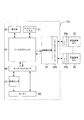
ここでは、実施形態によるリフト装置12のブロック図を示す図2Aについて言及する。リフト装置12は、天井走行リフト・システム及び床走行リフト・システムを含みながらもそれに限定されない、適合するあらゆるリフト装置に利用することができる。リフト装置12には、リフト装置12の機能を統合するマイクロプロセッサ23、一つ以上の積載装置25に関する負荷限界情報を受信する情報受信機24、モーター28の機能を制御し、情報受信機24により受信された負荷限界情報に基づきモーターの吊り上げ力を制限するように特になされたモーター・コントローラ26が含まれる。実施形態によっては、マイクロプロセッサ23、情報受信機24、モーター・コントローラ26を一つのチップに実装する。他の実施形態では、情報受信機24及びモーター・コントローラ26がマイクロプロセッサ23の機能内に組み込まれ、ソフトウェアあるいはソフトウェアとハードウェアの組み合わせで実現される。当業者はマイクロプロセッサ23、情報受信機24、モーター・コントローラ26が、他の適切な形態で実現され得ることを理解するであろう。
Reference is now made to FIG. 2A, which shows a block diagram of a
リフト装置12の実施形態によっては、表示具22及びコントロール・パネル21を備える場合がある。表示具22はリフト装置12の異なるモード(形態)やセッティング(設定)を表示するために使用することができる。表示具22はまた、一つ以上の積載装置の負荷限界や、リフト装置の総負荷限界(たとえば最低負荷限界)、あるいはこれに限らない情報を含む異なるパラメータを表示するために使用することができる。実施形態によっては、表示具22は液晶ディスプレー(LCD)あるいはこれに限らない適切な電子表示装置を備えることができる。実施形態によっては、表示具22は、たとえばシステムの適切な部品に張り付けたステッカーのように、他の適切な方法で情報を表示しても良い。コントロール・パネル21はリフト装置12を操作するために使用する。実施形態によっては、コントロール・パネル21は利用者あるいは介護者の指示を受け取る、有線あるいは無線のリモート・コントロール装置(図示しない)を備えても良い。
Depending on the embodiment of the
負荷センサ27はモーター28及びモーター・コントローラ26に接続されている。また、この負荷センサ27は、マイクロプロセッサ23に直接連結することもできる。あるいは、負荷センサ27は、フレキシブル・アーム13のように、積載装置と、あるいは積載装置とリフト装置12とを連結するコネクタとに連結することもできる。
The load sensor 27 is connected to the
リフト装置12に使用されるモーター28は、当業者の知る適切な電動モーターであればどれでもよい。モーター28は、直流モーターあるいは交流モーターのどちらでも使用できる。直流モーターが使用されるのであれば、供給電圧によってモーターの吊り上げ速度が制御される。交流モーターあるいはステッピング・モーターが使用されるのであれば、モーターの吊り上げ速度は供給電力の周波数により制御される。
The
好ましい実施形態では、情報受信機24は一つ以上の積載装置25からの負荷限界情報を受信する。各積載装置25は動作可能に連結され、情報受信機24へ負荷情報を送信する。次に情報受信機24及びマイクロプロセッサ23はその負荷限界情報に基づき、モーターの吊り上げ力を制限する。
In the preferred embodiment, the
情報受信機24に送られる負荷限界情報は様々な形態をとり得る。ある実施形態では、負荷限界情報は特定の積載装置25特有の定格荷重を含み得る。また別の実施形態では、負荷限界情報は情報受信機24に対し、所定の吊り上げ力を示すのみであって良い。
The load limit information sent to the
実施形態によっては、マイクロプロセッサ23及び情報受信機24は各積載装置25から受信した負荷限界情報とモーター28を比較し、モーターの吊り上げ力を最低負荷限界までに制限し得る。また、マイクロプロセッサ23は他の手段を使ってもモーターの吊り上げ力を制限し得る。
In some embodiments, the microprocessor 23 and the
ある実施形態においては、利用者がリフト装置12に直接負荷限界情報を入力する場合がある。これはコントロール・パネルを使用して行う。リフト装置12のいくつかの実施形態においては、利用者が各積載装置25の負荷限界情報を入力できる場合がある。あるいは、利用者が最低負荷限界を判断し、リフト装置12に単一の定格荷重を入力しても良い。一旦、最低負荷限界が設定される、あるいはモーターの吊り上げ力の限界が決定されると、リフト装置12はモーター28がその限界を超える吊り上げ力を供給しないようにする。
In some embodiments, a user may enter load limit information directly into the
いくつかの実施形態においては、リフト装置12はモーター28に動作可能に結合された最低一つのコネクタ(図示しない)を備える。このコネクタは、モーター28をスプレッダー14及びスリング15に連結するために使用するフレキシブル・アーム13であって良い。車輪やプーリ・システム等の他のコネクタは、モーター28を軌道11に結合するために使用できる。モーター28を一つ以上の積載装置25に接続するために、その他の適切なコネクタが使用され得る。
In some embodiments, the lifting
情報受信機24は各積載装置25からの負荷限界情報をマイクロプロセッサ23へ送るために使用される。この負荷限界情報は、各積載装置25の負荷限界を表示できる。たとえば軌道11、スプレッダー14バー、スリング15等の積載装置25の夫々は、それぞれが異なる負荷限界であって良い。積載装置25の負荷限界は、モーター28の負荷限界と異なっていても良い。実施形態によっては、リフト装置12がモーター28及びすべての積載装置25の負荷限界情報を確実に把握できるよう、情報受信機24は最初に各積載装置25からのすべての負荷限界情報を収集する。全ての負荷限界情報が集まると、マイクロプロセッサ23及びモーター・コントローラ26は、情報受信機24により受信された負荷限界情報に基づき、モーターの吊り上げ力を制限する。モーターの吊り上げ力に対するこの限界は、表示具22により利用者あるいは介護者に向け表示される。先に述べているように、表示具22にはあらゆる適切な電子表示装置、あるいは、たとえばリフト装置12の構成部品に張られた、あるいは他の適切な方法で実施されたステッカー等のその他の表示方法が含まれる。
The
再度図2Aを参照する。積載装置25からの負荷限界情報は、情報受信機24により受信される。情報受信機24は負荷限界情報をマイクロプロセッサ23へ送る。実施形態によっては、情報受信機24は最低負荷限界をマイクロプロセッサ23へ送る場合がある。実施形態によっては、情報受信機24はすべての負荷限界情報をマイクロプロセッサ23へ中継する場合がある。先に述べているように、情報受信機24はリフト装置12とは別個の部品であって良い。他の実施形態においては、情報受信機24はマイクロプロセッサ23の一部であっても良く、当業者には既知の方法でハードウェアあるいはソフトウェアで実現させても良い。
Reference is again made to FIG. 2A. Load limit information from the
情報受信機24と積載装置25との間の情報のやり取りは、適切などのような方法で実施しても良い。実施形態によっては、負荷限界情報は積載装置25に保存され、要求に応じて情報受信機24へと送られる。たとえば、積載装置25は特定の積載装置25についての負荷限界情報を情報受信機24と通信するトランスミッタ(図2Aには示されない)を備えることができる。この通信は積載装置25を情報受信機24へと連結する電気的接続を通じて行われる場合がある。この特徴の別の態様においては、積載装置25と情報受信機24との間の接続は、光ファイバー接続を通じた光信号であっても良い。
Information exchange between the
実施形態によっては、各積載装置25の個別の接続が、情報受信機24へ負荷限界情報を表示するために使用される。他の実施形態においては、通信は共有経路あるいは共有バスを通じて行われ、デイジー・チェーンやマルチプレックス等の既知の数多くの通信配置方式のいずれか、あるいはイーサネット(登録商標)規格やユニバーサル・シリアル・バス(USB)プロトコル等の多くの規格のいずれかを使用する。
In some embodiments, an individual connection for each
積載装置25と情報受信機24との間の通信は、無線により行われても良い。積載装置25からの負荷限界情報を通信するために、積載装置25は無線トランスミッタ(図2Aには示されない)あるいは無線トランシーバ(図2Aには示されない)を備えても良く、また情報受信機24は無線受信機(図2Aには示されない)あるいは無線トランシーバ(図2Aには示されない)を備えても良い。情報は、802.11規格、Bluetooth(登録商標)規格、その他既知のあるいは特注の無線方式等の、双方向通信規格を通じてやり取りが行われて良い。
Communication between the
情報は、電波による個体識別(RFID)タグ等の片方向通信方式を通じてやり取りしても良い。このような実施形態において、RFIDタグ(図示しない)は、情報受信機24からの問い合わせに応じ、負荷限界情報と共にその問合せに応答する。各積載装置25に関連付けられたRFIDタグは、積載装置25に組み込んでも良い。あるいは、RFIDタグはステッカーやその他の装着手段で積載装置25上に設置しても良い。積載装置25の定格荷重はステッカー上に表示しても良い。
Information may be exchanged through a one-way communication method such as a radio frequency identification (RFID) tag. In such an embodiment, an RFID tag (not shown) responds to the query with the load limit information in response to a query from the
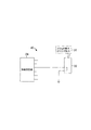
ここでは、別の実施形態によるリフト装置12aのブロック図を示す図2Bについて言及する。図2Bは図2Aと似ているが、情報受信機24と積載装置25との間の通信に無線周波数トランスミッタ/レシーバ29a及び無線周波数トランスミッタ/レシーバ29bを備えている。
Reference is now made to FIG. 2B which shows a block diagram of a
リフト装置12a内の情報受信機24はトランスミッタ/レシーバ29aを備え、各積載装置25はトランスミッタ/レシーバ29bを備える。先に述べているように、トランスミッタ/レシーバ29a及び29bにより、積載装置25は様々な多くの通信手段の一つを使い、負荷限界情報を情報受信機24へと伝達する。実施形態によっては、トランスミッタ/レシーバ29a及び29bは、情報が一方向にのみ流れる状態で、トランスミッタあるいはレシーバのどちらかのみを備えても良い。他の実施形態では、トランスミッタ/レシーバ29a及び29bは、両方向に送信でき、情報は積載装置25から、あるいは積載装置25へと移動し得る。実施形態によっては、このためにトランシーバを使用して良い。
The
先に述べた通信手段は例としてのみ挙げたものであり、積載装置25と情報受信機24との間の通信形態を限定しようとするものではないことは、当業者なら理解するであろう。トランスミッタ/レシーバ29a及びトランスミッタ/レシーバ29bのどのような組み合わせを用いた、適切などのような通信形態も利用可能である。
Those skilled in the art will appreciate that the communication means described above is only given as an example and is not intended to limit the form of communication between the
ここでは、いくつかの実施形態による、負荷限界情報を示すために1つあるいはそれ以上の特注キー30を利用する方法を示した図3A乃至3Cについて言及する。キー30は、情報受信機24と連結されたキー・インターフェイス40に受け入れられ得る。それにより、特定の積載装置の負荷限界情報は、物理的な積載装置25から切り離されても良い。そのかわりに、負荷限界情報は、リフト装置12へと連結可能な一つ以上の個別キー30に保存されても良い。各キー30は、キー・インターフェイス40を介して負荷限界情報を情報受信機24へと送信する。
Reference is now made to FIGS. 3A-3C illustrating a method of utilizing one or
積載装置メーカーは、積載装置25固有のキー30を製造しても良い。あるいは、リフト装置メーカーが様々な積載装置25に適した複数のキー30を、リフト装置12と共に供給しても良い。
The loader manufacturer may manufacture a key 30 unique to the
各キー30は特定の積載装置25と関連付けられ、ラベル34あるいはその他固有の定格荷重を表示する適切な表示具を備える。このラベル34は、キー・インターフェイス40に挿入した際、利用者または介護者から目視でき、関連付けられたモーター28または積載装置25の最低負荷限界を、利用者あるいは介護者が瞬時に判断できるようにしている。複数のキー30に関連付けられた複数のラベル34がある場合には、利用者または介護者は各キー30のラベル34を比較し、リフト装置12の最低負荷限界を判断する必要がある。さらに、表示具22も、負荷限界情報に基づきモーターの吊り上げ力の限度を表示する。実施形態によっては、キー30が表示具22を備える。
Each key 30 is associated with a
実施形態によっては、キー・インターフェイス40はキー30を1つのみ受け入れる。そのような実施形態の場合、システムの利用者またはシステムの設置者は、リフト装置12を使用する前にモーターの吊り上げ力の限度を判断する。多くの場合、この限度は個別の積載装置25及びモーター28の最低負荷限界である。他の実施形態では、キー・インターフェイス40には複数のキー30が挿入される。各キー30は、それぞれ異なる積載装置25を表す。次に情報受信機24は複数のキー30を比較し、リフト装置12の最低負荷限界を判断する。
In some embodiments, the
キー・インターフェイス40はリフト装置12上に直接設置しても良い。他のケースでは、キー・インターフェイス40はリフト装置12に連結された積載装置25の内の一つ、あるいはその他の適切な箇所に設置しても良い。その後、キー・インターフェイス40は情報受信機24と、先に述べた通信手段の一つにより、通信を行う。
The
図3Aに関し、キー30の一例が示されている。キー30には、所定の負荷限界を表示するラベル34およびキー回路32が含まれる。キー回路32はキー・インターフェイス40に受け入れられる。キー回路32と連結されているとき、キー・インターフェイス40は情報受信機24へ負荷限界情報を表示する。
With reference to FIG. 3A, an example of a key 30 is shown. The key 30 includes a label 34 for displaying a predetermined load limit and a
実施形態によっては、各キー30は積載装置25と関連付けられてこれを表すものとなり、関連付けられた積載装置25の負荷限界がキー30内に組み込まれる。別の実施形態においては、各キー30は複数の所定の吊り上げ力の一つあるいは吊り上げ力の範囲と関連付けられる。次にキー30は情報受信機24へ、どの所定の吊り上げ力あるいは吊り上げ力の範囲が積載装置25と関連付けられているかを表示する。
In some embodiments, each key 30 is associated with and represents a
ある実施形態によれば、各キー・インターフェイス40は複数の考え得るピンの組み合わせを備え、各ピンの組み合わせは所定の吊り上げ力または吊り上げ力の範囲と関連付けられる。従って、選択されたキーはキー回路32を介して対応するピンの組み合わせと係合し、モーターの吊り上げ力を、選択されたキー30及びピンの組み合わせと関連付けられた所定の吊り上げ力までに制限する。
According to certain embodiments, each
図3B及び3Cについて説明する。キー・インターフェイス40が、キー30の二つの例と共に示されている。キー・インターフェイス42は複数のピン44を備える。様々なピン44の組み合わせが、様々な所定の吊り上げ力に対応する。連結時、キー30はキー回路32を介して、キー30と関連付けられた所定の吊り上げ力をキー・インターフェイス42へ表示する。ピン44の異なる組み合わせと係合することで、キー30は異なる所定の吊り上げ力を多数表示することができる。実施形態によっては、ピン44の組み合わせとの係合の際、1本以上のピン44をアースに短絡するように構成しても良い。
3B and 3C will be described. A
他の実施形態では、キー30は、各積載装置25からの負荷限界情報を保存するメモリ装置(図示しない)を備える。このメモリ装置は様々な形態をとってよい。ある実施形態では、キー・インターフェイス42はUSBハブを備え、各キー30はフラッシュ・メモリを内蔵して積載装置と関連付けられた負荷限界情報を保存する。キー30内に負荷限界情報を保存するための他の形態として、揮発性及び不揮発性メモリであっても良い。
In another embodiment, the key 30 includes a memory device (not shown) that stores load limit information from each
図2Aに戻り説明する。負荷センサ27はモーターの吊り上げ力を測定する。この情報はマイクロプロセッサ23へと送られる。実施形態によっては、負荷センサ27により測定された負荷は、表示具22上で利用者または介護者へ向け表示される。実施形態によっては、負荷センサ27は、モーター28により消費される電流量を測定することで、モーターの吊り上げ力を測定する。当業者には知られていることであるが、モーター28により消費される電流量は、モーター28にかかる負荷に比例する。モーター28がより大きな負荷を受け入れるためにより大きなトルクを必要とする場合、より多くの電流量を消費する。そのため、負荷センサ27は、モーター28が吊り上げ動作中に電源(図示しない)から消費する電流を測定し、モーターの吊り上げ力を推測する。
Returning to FIG. The load sensor 27 measures the lifting force of the motor. This information is sent to the microprocessor 23. In some embodiments, the load measured by the load sensor 27 is displayed on the
任意のモーター28に関し、消費電流量とモーターの吊り上げ力とを関連付ける表が提供できる。吊り上げ中の電流消費と吊り上げられている重量との関係は、実験により判断でき、またモーターのメーカーから入手することもできる。図2Aについて、負荷センサ27はモーターの電源に連結することができる。負荷センサ27は、モーター28が電源から消費する電流量を測定し、表の検索のためにその情報をマイクロプロセッサ23へ送信する。そのため、実施形態によっては、任意の負荷に対するモーター28の吊り上げ力を判断するため、モーター28に供給される電流の測定結果がモーター・コントローラ26及びマイクロプロセッサ23に利用される。この測定にはモーター28に発生する突入電流を考慮する場合がある。実施形態によっては、電流測定に遅延を起こすことで定常電流を測定しても良い。他の実施形態では、突入電流についての説明が可能なあらゆる適切な手段が利用可能である。
For any given
他の実施形態においては、負荷センサ27は適切な力測定トランスデューサを利用して実装される。このトランスデューサはリフト装置12に連結され、リフト装置12にかかる鉛直力を直接測定する。この分野で知られたトランスデューサの例としては、歪みゲージ、圧力センサ、圧電センサが含まれる。このような測定トランスデューサはリフト装置12にかかる吊り上げ力を、モーター28の係合の有無に関わらず、測定可能である。このような場合、その負荷を吊り上げる前及び電流を供給する前に、モーター・コントローラ26及びマイクロプロセッサ23へ負荷情報を供給することが可能である。
In other embodiments, the load sensor 27 is implemented utilizing a suitable force measurement transducer. This transducer is connected to the
リフト装置12が積載装置25からの負荷限界情報を受け取り、モーターの吊り上げ力を測定する手段を備えていれば、マイクロプロセッサ23及びモーター・コントローラ26は、その負荷限界情報に基づき、リフト装置12の作動を制限することができる。実施形態によっては、モーターの吊り上げ力は積載装置25の一つからの負荷限界情報に含まれる負荷限界までに制限される。多くの場合、この限界は最低負荷限界である。ただし、これは常にそうでなければならないわけではない。
If the
モーターの吊り上げ力を制限するために、モーター・コントローラ26は周期的に負荷センサ27を監視する制御システムを実装することができる。負荷センサ27がモーター・コントローラ26に対し、負荷重量がリフト装置12の定格荷重に近づき、あるいは超えたことを示した場合、モーター・コントローラ26はモーターの係合を解除し、リフト装置12の吊り上げ動作を停止させる。モーターの吊り上げ力が、負荷限界情報に基づく設定限界を超えた場合、他の動作も起こり得る。実施形態によっては、リフト装置12はモーターの吊り上げ力が設定限界を超えたことを、利用者あるいは介護者へ向け表示する。
In order to limit the lifting force of the motor, the
図4Aについて説明する。フローチャートには、測定結果を受け取り、情報受信機24から受け取った負荷限界情報と比較する手段50が示される。ステップ(52)では、この手段によりモーターの吊り上げ力が測定される。測定は先に述べた様々な手段の内の一つを使用して行われる。次に、ステップ(54)で負荷限界情報についての比較が行われ、モーターの吊り上げ力が、各積載装置からの負荷限界情報に基づき、情報受信機24によって設定された限界を超えるかどうかを判断する。限界を超えていなければ、リフト装置12の作動はステップ(56)へと進む。そうでなければ、モーターの吊り上げ力は限界を超え、マイクロプロセッサ23はステップ(58)でこの過負荷状態に対する指示を発する。この指示にはモーター28の停止、及び限界を超えた旨の表示が含まれる。
FIG. 4A will be described. The flowchart shows a
実施形態によっては、リフト装置12により吊り上げられる負荷は判断しない。実施形態によっては、リフト装置12のモーター28に供給される電流は適切なレベルに制限される。このような実施形態においては、システムはモーターの吊り上げ力を積極的には監視しない。そのため、実施形態によっては負荷センサ27を備えない。実施形態によっては、モーターの吊り上げ力を制限する、特定の数値が設定される。実施形態によっては、最大電流が設定される。モーター28の要求電流が周知であれば、リフト装置12はモーター28の消費電流と結果としての吊り上げ力との関係を利用する。先に述べたとおり、モーター28の吊り上げ力は消費される電流と正比例する。そのため、モーター28に供給される最大電流は希望する限界吊り上げ力に対応する最大電流に制限され得る。モーター28の電流には限度があるため、最大電流と比例する力も、その限度を超える力を出すことはできない。
In some embodiments, the load lifted by the
次に図4Bについて説明する。図示されているのは手段60のフローチャートで、特にモーター28に供給される電流の制限に関するシステムを含む。ステップ(60)において、リフト装置12は情報受信機24からの積載装置に関する負荷限界情報を読み込む。次に、ステップ(64)において判断が下される。ステップ(64)は、モーターの吊り上げ力を制限するリフト装置の設定限界についての適切な最大電流と関連している。ある実施形態において、最低負荷限界は、リフト装置12を全積載装置25の負荷限界内に確実に留めるために利用される。最後に、この判断に基づき、ステップ(66)でモーターの吊り上げ力を制限する最大電流が設定される。
Next, FIG. 4B will be described. Shown is a flow chart of the
先に触れているように、電流の制限方法は突入電流に対応する。モーターの吊り上げ力が限界電流に達した場合、リフト装置12はエラー状況を利用者または介護者へと伝える。実施形態によってはモーター28の吊り上げ動作が停止する。また、リフト装置12またはモーター28は、利用者がすでに吊り上げられている場合に、下降しないようロック機構を作動させる。
As mentioned earlier, the current limiting method corresponds to the inrush current. When the lifting force of the motor reaches the limit current, the
図4A及び図4Bで示された方法は、ハードウェアおよびソフトウェアの両方で実行可能である。ソフトウェアで実行する場合、負荷限界情報及び最大電流はソフトウェア変数として保存される。同様に、方法50及び60は、当業者の知る設計法に従い、アナログまたはデジタル・ハードウェア構成機器を利用して実行できる。
The method illustrated in FIGS. 4A and 4B can be performed in both hardware and software. When implemented in software, load limit information and maximum current are stored as software variables. Similarly,
ここまでの記載内容は実施形態の例を示すものであるが、記載した実施形態の特徴または機能は、記載した実施形態の作動についての要旨及び原理を逸脱することなく、改変が可能であることを理解されたい。そのため、ここに述べた内容は発明の説明を意図したものでこれを限定するものではなく、当業者であれば、添付された請求項で定義される本発明の範囲から逸脱することなく変更及び改変が可能であることを理解するであろう。 The contents described so far show examples of the embodiments, but the features or functions of the described embodiments can be modified without departing from the spirit and principle of the operation of the described embodiments. I want you to understand. Therefore, the content herein described is intended to be illustrative of the invention and not limiting thereof, and those skilled in the art will recognize modifications and changes without departing from the scope of the invention as defined in the appended claims. It will be understood that modifications are possible.
Claims (39)
38. A lift system according to any one of claims 29 , 36 , 37 , wherein at least one of the loading devices comprises a spreader bar.
Applications Claiming Priority (3)
| Application Number | Priority Date | Filing Date | Title |
|---|---|---|---|
| CA2692894A CA2692894C (en) | 2010-02-12 | 2010-02-12 | Lift apparatus and system |
| CA2,692,894 | 2010-02-12 | ||
| PCT/CA2011/000003 WO2011097698A1 (en) | 2010-02-12 | 2011-01-06 | Lift apparatus and system |
Publications (2)
| Publication Number | Publication Date |
|---|---|
| JP2013519600A JP2013519600A (en) | 2013-05-30 |
| JP5830472B2 true JP5830472B2 (en) | 2015-12-09 |
Family
ID=44366917
Family Applications (1)
| Application Number | Title | Priority Date | Filing Date |
|---|---|---|---|
| JP2012552212A Active JP5830472B2 (en) | 2010-02-12 | 2011-01-06 | Lift device and system |
Country Status (7)
| Country | Link |
|---|---|
| US (1) | US8910325B2 (en) |
| EP (1) | EP2534084B1 (en) |
| JP (1) | JP5830472B2 (en) |
| CN (1) | CN102770365B (en) |
| AU (1) | AU2011214911B2 (en) |
| CA (1) | CA2692894C (en) |
| WO (1) | WO2011097698A1 (en) |
Families Citing this family (32)
| Publication number | Priority date | Publication date | Assignee | Title |
|---|---|---|---|---|
| US10045895B2 (en) | 2011-08-24 | 2018-08-14 | Liko Research & Development Ab | Patient stand assist and therapy devices and methods |
| EP2815353B1 (en) | 2012-02-17 | 2019-05-08 | Columbus McKinnon Corporation | Material lifting system and method |
| EP2684550B1 (en) * | 2012-07-12 | 2016-09-21 | Liko Research & Development AB | Patient stand assist and therapy devices and methods |
| US20140020175A1 (en) * | 2012-07-12 | 2014-01-23 | Steven A. Dixon | Monitoring systems devices and methods for patient lifts |
| US9598269B2 (en) * | 2014-04-04 | 2017-03-21 | David R. Hall | Motorized lifting device with a grooved drum for lifting a load and determining a weight of the load while lifting |
| US9567195B2 (en) * | 2013-05-13 | 2017-02-14 | Hall David R | Load distribution management for groups of motorized lifting devices |
| WO2015024569A1 (en) * | 2013-08-22 | 2015-02-26 | Linak A/S | Patient lifter |
| CN103720557B (en) * | 2013-09-27 | 2017-07-11 | 广州曼纽科实验分析仪器有限公司 | Intelligent shift system |
| US9511245B2 (en) * | 2014-03-28 | 2016-12-06 | International Business Machines Corporation | Safety harness monitoring and alerting system |
| US9711029B2 (en) | 2014-10-31 | 2017-07-18 | Hill-Rom Services, Inc. | Equipment, dressing and garment wireless connectivity to a patient bed |
| ES2933482T3 (en) * | 2014-11-17 | 2023-02-09 | Arjo Ip Holding Ab | Configurable patient ceiling lift |
| US10729606B2 (en) * | 2015-05-15 | 2020-08-04 | Liko Research & Development Ab | Adaptive mobility lift |
| EP3111906B1 (en) | 2015-07-01 | 2023-05-10 | Liko Research & Development AB | Person lifting devices and methods for operating person lifting devices |
| EP3111907B1 (en) | 2015-07-01 | 2021-03-10 | Liko Research & Development AB | Person lifting devices with accessory detection features and methods for operating the same |
| US10314758B2 (en) | 2015-07-31 | 2019-06-11 | Allen Medical Systems, Inc. | Person support apparatus with tracking features |
| US10376434B2 (en) * | 2015-07-31 | 2019-08-13 | Liko Research & Developmetn AB | Person lift devices and scale assemblies for person lift devices including accessory tracking features |
| DE102015118434A1 (en) | 2015-10-28 | 2017-05-04 | Terex MHPS IP Management GmbH | Method for operating at least two hoists in a group operation and arrangement with at least two hoists |
| CN107028611A (en) * | 2016-02-03 | 2017-08-11 | 上海联影医疗科技有限公司 | A kind of body weight detection method and system for Medical Devices |
| US20170325524A1 (en) * | 2016-05-12 | 2017-11-16 | Elwha LLC, a limited liability company of the State of Delaware | Systems, devices, and methods including a lift garment |
| US10828216B2 (en) | 2017-03-03 | 2020-11-10 | Medline Industries, Inc. | Inflatable patient repositioning sheet |
| US10772778B2 (en) | 2017-04-25 | 2020-09-15 | Medline Industries, Inc. | Patient repositioning sheet and sling |
| US11007101B2 (en) * | 2017-05-02 | 2021-05-18 | Liko Research & Development Ab | Adaptive compensation of wear in person lifting assemblies |
| US11096852B2 (en) | 2017-06-01 | 2021-08-24 | Liko Research & Development Ab | Systems for monitoring person lifting devices using load tension pins |
| WO2019083315A1 (en) * | 2017-10-27 | 2019-05-02 | 주식회사 릴테크 | Elevating device for high-elevation installation equipment and method for controlling same |
| EP3510987B1 (en) * | 2018-01-11 | 2022-03-02 | Liko Research & Development AB | Person lifting apparatuses including lifting straps and methods of operation |
| US11191688B2 (en) | 2018-01-11 | 2021-12-07 | Liko Research & Development Ab | Person lifting apparatuses including lifting straps and methods of operation |
| CN108750926B (en) * | 2018-05-29 | 2023-11-03 | 中铁大桥局集团有限公司 | Intelligent lifting hook, monitoring system and use method of intelligent lifting hook |
| US11344462B2 (en) | 2018-09-19 | 2022-05-31 | Liko Research & Development Ab | Person lifting apparatuses including lifting straps and methods of operation based on current draw |
| IT201800010918A1 (en) * | 2018-12-10 | 2020-06-10 | Manitou Italia Srl | Improved safety system for self-propelled machinery. |
| CN109431718A (en) * | 2018-12-14 | 2019-03-08 | 辽宁福之卉科技发展有限公司 | A kind of omnidirectional's intelligence shift equipment |
| EP3935289B1 (en) * | 2019-03-04 | 2024-01-03 | Linak A/S | A linear actuator system and a method of setting up and programming power limit values for such an actuator system |
| US11331235B2 (en) | 2019-09-13 | 2022-05-17 | Medline Industries, Lp | Patient repositioning sheet, system, and method |
Family Cites Families (13)
| Publication number | Priority date | Publication date | Assignee | Title |
|---|---|---|---|---|
| US9021A (en) * | 1852-06-15 | Preparing cotton yarn for the manufacture of duck and other coarse | ||
| US3877421A (en) | 1973-09-07 | 1975-04-15 | Cicero C Brown | Patient lift and exercise apparatus |
| EP0399836A3 (en) | 1989-05-25 | 1991-10-09 | F J Payne (Manufacturing) Ltd | Lifting device |
| US6289534B1 (en) * | 1998-07-31 | 2001-09-18 | Hill-Rom Services, Inc. | Patient lift |
| DE29818691U1 (en) | 1998-10-21 | 1999-02-11 | Okin Ges Fuer Antriebstechnik | linear actuator |
| MXPA03003454A (en) * | 2000-10-18 | 2003-07-14 | Mhe Technologies Inc | Host apparatus. |
| CA2586129C (en) * | 2001-03-29 | 2010-05-04 | Kci Licensing, Inc. | Prone positioning therapeutic bed |
| US6671905B2 (en) * | 2001-03-29 | 2004-01-06 | Kci Licensing, Inc. | Prone positioning therapeutic bed |
| CA2369668C (en) | 2002-01-28 | 2010-05-04 | Waverley Glen Systems Ltd. | Personal lift device |
| US7932687B2 (en) | 2005-11-09 | 2011-04-26 | Linak A/S | Actuator system |
| CA2669584A1 (en) * | 2006-11-14 | 2008-05-22 | Atlas Devices Llc | Multiple line powered rope ascender and portable hoist |
| JP2008308238A (en) * | 2007-06-12 | 2008-12-25 | Kobe Steel Ltd | Control device for conveyance tool |
| US8474794B2 (en) | 2009-03-06 | 2013-07-02 | Liko Research & Development Ab | Lift control systems for lifting devices and lifting devices comprising the same |
-
2010
- 2010-02-12 CA CA2692894A patent/CA2692894C/en active Active
-
2011
- 2011-01-06 WO PCT/CA2011/000003 patent/WO2011097698A1/en active Application Filing
- 2011-01-06 EP EP11741766.7A patent/EP2534084B1/en active Active
- 2011-01-06 US US13/577,805 patent/US8910325B2/en active Active
- 2011-01-06 AU AU2011214911A patent/AU2011214911B2/en active Active
- 2011-01-06 JP JP2012552212A patent/JP5830472B2/en active Active
- 2011-01-06 CN CN201180009065.7A patent/CN102770365B/en active Active
Also Published As
| Publication number | Publication date |
|---|---|
| EP2534084A4 (en) | 2014-06-25 |
| AU2011214911B2 (en) | 2015-05-07 |
| AU2011214911A1 (en) | 2012-08-30 |
| WO2011097698A8 (en) | 2012-09-07 |
| CN102770365B (en) | 2014-12-10 |
| WO2011097698A1 (en) | 2011-08-18 |
| US20130038263A1 (en) | 2013-02-14 |
| CA2692894A1 (en) | 2011-08-12 |
| CA2692894C (en) | 2017-06-27 |
| EP2534084B1 (en) | 2017-09-27 |
| EP2534084A1 (en) | 2012-12-19 |
| CN102770365A (en) | 2012-11-07 |
| JP2013519600A (en) | 2013-05-30 |
| US8910325B2 (en) | 2014-12-16 |
Similar Documents
| Publication | Publication Date | Title |
|---|---|---|
| JP5830472B2 (en) | Lift device and system | |
| EP2862552B1 (en) | Sling bar or lift strap connector having an integrated scale with tilt compensation | |
| US10741284B2 (en) | Universal calibration system | |
| EP3791848A1 (en) | Patient support apparatus having an integrated limb compression device | |
| EP3123998A1 (en) | Patient lift system with component compatibility features | |
| US11446193B2 (en) | Person lift systems | |
| US11344462B2 (en) | Person lifting apparatuses including lifting straps and methods of operation based on current draw | |
| CN104355235B (en) | The control method of lifting mechanism, control device and lifting mechanism | |
| WO2015040251A1 (en) | Method and arrangement for calibrating the load control system of a lift | |
| EP1269960B1 (en) | Invalid hoist | |
| WO2016108266A1 (en) | Bed senor and bed embedded with same | |
| US11096852B2 (en) | Systems for monitoring person lifting devices using load tension pins | |
| JP5184288B2 (en) | Sensor control system | |
| KR101817062B1 (en) | Apparatus for controlling data transmission in measuring weight system for forklift | |
| CN220180827U (en) | Electric power secondary equipment debugging shallow | |
| EP3528764B1 (en) | Hospital device for patient support | |
| US11786430B2 (en) | Patient lift and sling having wireless communication | |
| JP2010136768A (en) | Sensor control system | |
| JP2000309488A (en) | Power supply monitoring control device for nursing hoist device | |
| TWM364701U (en) | Wireless safety control device for crane cable |
Legal Events
| Date | Code | Title | Description |
|---|---|---|---|
| A621 | Written request for application examination |
Free format text: JAPANESE INTERMEDIATE CODE: A621 Effective date: 20131225 |
|
| A977 | Report on retrieval |
Free format text: JAPANESE INTERMEDIATE CODE: A971007 Effective date: 20140903 |
|
| A131 | Notification of reasons for refusal |
Free format text: JAPANESE INTERMEDIATE CODE: A131 Effective date: 20141030 |
|
| A601 | Written request for extension of time |
Free format text: JAPANESE INTERMEDIATE CODE: A601 Effective date: 20150119 |
|
| A601 | Written request for extension of time |
Free format text: JAPANESE INTERMEDIATE CODE: A601 Effective date: 20150224 |
|
| A521 | Request for written amendment filed |
Free format text: JAPANESE INTERMEDIATE CODE: A523 Effective date: 20150326 |
|
| TRDD | Decision of grant or rejection written | ||
| A01 | Written decision to grant a patent or to grant a registration (utility model) |
Free format text: JAPANESE INTERMEDIATE CODE: A01 Effective date: 20151001 |
|
| A61 | First payment of annual fees (during grant procedure) |
Free format text: JAPANESE INTERMEDIATE CODE: A61 Effective date: 20151026 |
|
| R150 | Certificate of patent or registration of utility model |
Ref document number: 5830472 Country of ref document: JP Free format text: JAPANESE INTERMEDIATE CODE: R150 |
|
| R250 | Receipt of annual fees |
Free format text: JAPANESE INTERMEDIATE CODE: R250 |
|
| R250 | Receipt of annual fees |
Free format text: JAPANESE INTERMEDIATE CODE: R250 |
|
| R250 | Receipt of annual fees |
Free format text: JAPANESE INTERMEDIATE CODE: R250 |
|
| R250 | Receipt of annual fees |
Free format text: JAPANESE INTERMEDIATE CODE: R250 |
|
| R250 | Receipt of annual fees |
Free format text: JAPANESE INTERMEDIATE CODE: R250 |
|
| R250 | Receipt of annual fees |
Free format text: JAPANESE INTERMEDIATE CODE: R250 |