JP5826855B2 - Injection molding machine having at least two toggle lever mechanisms - Google Patents
Injection molding machine having at least two toggle lever mechanisms Download PDFInfo
- Publication number
- JP5826855B2 JP5826855B2 JP2013533130A JP2013533130A JP5826855B2 JP 5826855 B2 JP5826855 B2 JP 5826855B2 JP 2013533130 A JP2013533130 A JP 2013533130A JP 2013533130 A JP2013533130 A JP 2013533130A JP 5826855 B2 JP5826855 B2 JP 5826855B2
- Authority
- JP
- Japan
- Prior art keywords
- supported
- support
- injection molding
- molding machine
- toggle lever
- Prior art date
- Legal status (The legal status is an assumption and is not a legal conclusion. Google has not performed a legal analysis and makes no representation as to the accuracy of the status listed.)
- Active
Links
- 230000007246 mechanism Effects 0.000 title claims description 55
- 238000001746 injection moulding Methods 0.000 title claims description 35
- 230000005540 biological transmission Effects 0.000 claims description 20
- 238000001816 cooling Methods 0.000 claims description 20
- 238000002347 injection Methods 0.000 claims description 15
- 239000007924 injection Substances 0.000 claims description 15
- 239000000463 material Substances 0.000 claims description 6
- 238000012545 processing Methods 0.000 claims description 5
- 238000006243 chemical reaction Methods 0.000 description 4
- 229920003023 plastic Polymers 0.000 description 4
- 239000004033 plastic Substances 0.000 description 4
- 229910010293 ceramic material Inorganic materials 0.000 description 2
- 230000001419 dependent effect Effects 0.000 description 2
- 238000004519 manufacturing process Methods 0.000 description 2
- 239000007769 metal material Substances 0.000 description 2
- 238000000034 method Methods 0.000 description 2
- 241000239290 Araneae Species 0.000 description 1
- 230000006978 adaptation Effects 0.000 description 1
- 238000013459 approach Methods 0.000 description 1
- 239000000969 carrier Substances 0.000 description 1
- 238000010276 construction Methods 0.000 description 1
- 238000011990 functional testing Methods 0.000 description 1
- 238000012423 maintenance Methods 0.000 description 1
- 238000012986 modification Methods 0.000 description 1
- 230000004048 modification Effects 0.000 description 1
- 239000012254 powdered material Substances 0.000 description 1
Images


Classifications
-
- B—PERFORMING OPERATIONS; TRANSPORTING
- B29—WORKING OF PLASTICS; WORKING OF SUBSTANCES IN A PLASTIC STATE IN GENERAL
- B29C—SHAPING OR JOINING OF PLASTICS; SHAPING OF MATERIAL IN A PLASTIC STATE, NOT OTHERWISE PROVIDED FOR; AFTER-TREATMENT OF THE SHAPED PRODUCTS, e.g. REPAIRING
- B29C45/00—Injection moulding, i.e. forcing the required volume of moulding material through a nozzle into a closed mould; Apparatus therefor
- B29C45/17—Component parts, details or accessories; Auxiliary operations
- B29C45/64—Mould opening, closing or clamping devices
- B29C45/66—Mould opening, closing or clamping devices mechanical
- B29C45/661—Mould opening, closing or clamping devices mechanical using a toggle mechanism for mould clamping
-
- B—PERFORMING OPERATIONS; TRANSPORTING
- B22—CASTING; POWDER METALLURGY
- B22D—CASTING OF METALS; CASTING OF OTHER SUBSTANCES BY THE SAME PROCESSES OR DEVICES
- B22D17/00—Pressure die casting or injection die casting, i.e. casting in which the metal is forced into a mould under high pressure
- B22D17/20—Accessories: Details
- B22D17/26—Mechanisms or devices for locking or opening dies
- B22D17/266—Mechanisms or devices for locking or opening dies hydraulically
-
- B—PERFORMING OPERATIONS; TRANSPORTING
- B28—WORKING CEMENT, CLAY, OR STONE
- B28B—SHAPING CLAY OR OTHER CERAMIC COMPOSITIONS; SHAPING SLAG; SHAPING MIXTURES CONTAINING CEMENTITIOUS MATERIAL, e.g. PLASTER
- B28B1/00—Producing shaped prefabricated articles from the material
- B28B1/24—Producing shaped prefabricated articles from the material by injection moulding
-
- B—PERFORMING OPERATIONS; TRANSPORTING
- B28—WORKING CEMENT, CLAY, OR STONE
- B28B—SHAPING CLAY OR OTHER CERAMIC COMPOSITIONS; SHAPING SLAG; SHAPING MIXTURES CONTAINING CEMENTITIOUS MATERIAL, e.g. PLASTER
- B28B7/00—Moulds; Cores; Mandrels
- B28B7/0002—Auxiliary parts or elements of the mould
- B28B7/0014—Fastening means for mould parts, e.g. for attaching mould walls on mould tables; Mould clamps
-
- B—PERFORMING OPERATIONS; TRANSPORTING
- B29—WORKING OF PLASTICS; WORKING OF SUBSTANCES IN A PLASTIC STATE IN GENERAL
- B29C—SHAPING OR JOINING OF PLASTICS; SHAPING OF MATERIAL IN A PLASTIC STATE, NOT OTHERWISE PROVIDED FOR; AFTER-TREATMENT OF THE SHAPED PRODUCTS, e.g. REPAIRING
- B29C45/00—Injection moulding, i.e. forcing the required volume of moulding material through a nozzle into a closed mould; Apparatus therefor
- B29C45/17—Component parts, details or accessories; Auxiliary operations
- B29C45/64—Mould opening, closing or clamping devices
- B29C45/68—Mould opening, closing or clamping devices hydro-mechanical
- B29C45/681—Mould opening, closing or clamping devices hydro-mechanical using a toggle mechanism as mould clamping device
-
- B—PERFORMING OPERATIONS; TRANSPORTING
- B29—WORKING OF PLASTICS; WORKING OF SUBSTANCES IN A PLASTIC STATE IN GENERAL
- B29C—SHAPING OR JOINING OF PLASTICS; SHAPING OF MATERIAL IN A PLASTIC STATE, NOT OTHERWISE PROVIDED FOR; AFTER-TREATMENT OF THE SHAPED PRODUCTS, e.g. REPAIRING
- B29C45/00—Injection moulding, i.e. forcing the required volume of moulding material through a nozzle into a closed mould; Apparatus therefor
- B29C45/17—Component parts, details or accessories; Auxiliary operations
- B29C45/64—Mould opening, closing or clamping devices
- B29C45/68—Mould opening, closing or clamping devices hydro-mechanical
- B29C45/683—Mould opening, closing or clamping devices hydro-mechanical using both a toggle mechanism as mould closing device and another mechanism as mould clamping device
Landscapes
- Engineering & Computer Science (AREA)
- Mechanical Engineering (AREA)
- Manufacturing & Machinery (AREA)
- Ceramic Engineering (AREA)
- Chemical & Material Sciences (AREA)
- Moulds For Moulding Plastics Or The Like (AREA)
- Injection Moulding Of Plastics Or The Like (AREA)
Description
関連出願への参照
本出願は、2010年10月18日付出願に係るドイツ特許願第102010048560.8号の優先権を主張するものであり、その開示内容は本願の対象でもあることを明記する。
Reference to related applications This application claims the priority of German Patent Application No. 102010048560.8 filed on Oct. 18, 2010, the disclosure of which is also the subject of this application.
技術分野
本発明は、プラスチックおよびその他の可塑化可能な材料を加工するための、少なくとも2つのトグルレバー機構を備える請求項1の上位概念部(前置部)による射出成形機に関する。
TECHNICAL FIELD The present invention relates to an injection molding machine with a superordinate conceptual part (front part) according to claim 1 comprising at least two toggle lever mechanisms for processing plastics and other plasticizable materials.
請求項1の上位概念部の基礎をなす特許文献1から、型締ユニットを有する射出成形機が公知であり、この型締ユニットでは、サーボモータとして構成された2つの別個の駆動ユニットを介して2つのトグルレバー機構を、型平行度の調整のために制御駆動することができる。サーボモータは、ナットに接続されたスピンドルを駆動し、このスピンドルはトグルレバー機構を作動するように支承されている。裏面の支持プレートには駆動モータが型の高さ(レベル)調整装置としても固定されており、これにより運動質量が低減されている。 From patent document 1 which forms the basis of the superordinate conceptual part of claim 1, an injection molding machine having a clamping unit is known, in this clamping unit via two separate drive units configured as servomotors. Two toggle lever mechanisms can be controlled to adjust the mold parallelism. The servo motor drives a spindle connected to the nut, and this spindle is supported to operate a toggle lever mechanism. A drive motor is also fixed to the back support plate as a mold height (level) adjusting device, thereby reducing the kinetic mass.
特許文献2から、射出成形機用の型締ユニットが公知であり、この型締ユニットではスライド−クランク変換機構(Schubkurbel)を介してダブル・トグルレバー機構が駆動される。このスライド−クランク変換機構とその駆動ユニットとは裏面の支持エレメントに支承されている。 From Patent Document 2, a mold clamping unit for an injection molding machine is known, and in this mold clamping unit, a double toggle lever mechanism is driven via a slide-crank conversion mechanism (Schubkurbel). The slide-crank conversion mechanism and its drive unit are supported by a back support element.
特許文献3から、2つのトグルレバー機構を有する射出成形機が公知であり、この2つのトグルレバー機構はY字形トグルレバーとして構成されている。この場合、駆動モータは駆動軸に対して横方向に配置される。 From Patent Document 3, an injection molding machine having two toggle lever mechanisms is known, and the two toggle lever mechanisms are configured as Y-shaped toggle levers. In this case, the drive motor is disposed laterally with respect to the drive shaft.
上記従来技術から出発して本発明の基礎とする課題は、冒頭に述べた形式の射出成形機を、型支持体の平行度を静止状態でも動的状態でも調整することができるようにさらに改善することである。 Starting from the above prior art, the problem underlying the present invention is to further improve the injection molding machine of the type described at the beginning so that the parallelism of the mold support can be adjusted both in a stationary state and in a dynamic state. It is to be.
この課題は、請求項1の特徴を備える射出成形機によって解決される。
即ち本発明の一視点により、可塑化可能な材料を加工するための射出成形機であって、機械脚部に配置された型締ユニットを有し、該型締ユニットは、定置の型支持体と可動の型支持体との間に収容可能な少なくとも1つの射出成形型と、互いに独立して各駆動ユニットにより駆動可能な2つのトグルレバー機構を備える少なくとも1つのトグルレバーペアと、発生する力を受け止める力伝達エレメントとを有し、該力伝達エレメントは、前記定置の型支持体を支持エレメントと接続し、前記トグルレバー機構は、可動の支承プレートに支承されており、前記支承プレートは、前記射出成形機において、複数の力伝達エレメントに可動に支承されており、前記複数の駆動ユニットは、可動の前記支承プレートに支承されており、前記支承プレートには、少なくとも2つのトグルレバー機構のための作動エレメントが支承されていること、前記支承プレートの案内部として働く複数の力伝達エレメントが、互いに対称的に中心軸に関し対向して配されること、そして全ての前記駆動ユニットが、可動の前記支承プレートに、前記力伝達エレメントから離隔して支承されていること、を特徴とする射出成形機が提供される。
尚、本願の特許請求の範囲に付記されている図面参照符号は、専ら本発明の理解の容易化のためのものであり、図示の形態への限定を意図するものではないことを付言する。
This problem is solved by an injection molding machine having the features of claim 1.
That According to one aspect of the present invention, there is provided a injection molding machine for processing a plasticizing material capable, it has a mold clamping unit disposed in the machine leg, mold clamping unit, mold carriers stationary And at least one injection mold that can be accommodated between the body and the movable mold support, and at least one toggle lever pair comprising two toggle lever mechanisms that can be driven by each drive unit independently of each other. A force transmitting element for receiving force, the force transmitting element connecting the stationary mold support to the supporting element, and the toggle lever mechanism is supported by a movable supporting plate, the supporting plate being In the injection molding machine, the plurality of force transmission elements are movably supported, and the plurality of drive units are supported by the movable support plate. The actuating element for at least two toggle lever mechanisms is supported on the joint, and a plurality of force transmission elements acting as guide portions for the supporting plate are arranged symmetrically and opposed to each other with respect to the central axis. And an injection molding machine characterized in that all the drive units are supported on the movable support plate at a distance from the force transmission element.
It should be noted that the reference numerals attached to the claims of the present application are only for facilitating the understanding of the present invention, and are not intended to limit the illustrated embodiment.
トグルレバー機構は公知のように別個の駆動ユニットまたは別個の駆動機構によって駆動されるが、これらの駆動ユニットはトグルレバー運動の際に同様に運動する支承プレートに支承されており、この支承プレートにはトグルレバー機構を作動するための作動エレメントが支承されている。トグルレバー運動によってこのプレートは運動の開始時には可動の型支持体とほぼ同じような関係で運動するが、型の運動の終了近くではこの支承プレートはなおミリメータ領域で運動し、一方、型支持体はすでに形締め状態にある。これにより支承プレートの位置を工具運動に対する基準尺度として使用することができる。なぜならこの位置における(力)変換関係(Uebersetzungsverhaeltnis)が形締めの際にもっとも正確だからである。従来技術では、とりわけ型締め運動の際に駆動モータを介して制御が行われるが、今や選択された構成により対応する制御の際に、これによりより高められた精度を型締めの際にもさらに調整することができる。精度をさらに高めるために、支承プレートが機械脚部において、または定置の型支持体と支持エレメントとの間に配置された力伝達エレメントにおいて横木ロッドのように案内される。 The toggle lever mechanism is driven by a separate drive unit or a separate drive mechanism as is well known, but these drive units are supported by a support plate that moves in the same way during the toggle lever movement, An operating element for operating the toggle lever mechanism is supported. Toggle lever movement causes the plate to move in a similar relationship to the movable mold support at the beginning of the movement, but near the end of the mold movement, the bearing plate still moves in the millimeter range while the mold support Is already in a clamped state. This allows the position of the support plate to be used as a reference measure for tool movement. This is because the (force) conversion relationship (Uebersetzungsverhaeltnis) at this position is the most accurate at the time of clamping. In the prior art, the control is carried out via the drive motor, especially during the clamping movement, but now with the corresponding control according to the selected configuration, this further increases the accuracy even during clamping. Can be adjusted. In order to further increase the accuracy, the bearing plate is guided like a crossbar rod in the machine leg or in a force transmission element arranged between the stationary mold support and the support element.
確かに駆動モータ自体を支承プレートに支承することにより、移動すべき質量が増大する。しかしこのことは意図的に受け入れられる。なぜならこれは非常に剛性のプレートとして構成されており、多機能部材として同時に使用することができるからである。加えてこの支承プレートをその駆動ユニットとともに独立の構成ユニットとして前もって完全に組み立てておき、機械に組み込むことができる。製造業者にとってこのことは、一方ではより良好な予備完成品を意味し、ここでは機械の他の部分と「組合わせる」前にすでに前記構成ユニットにおいて機能テストを実行することができる。さらにこの構成ユニット全体をそれ自体別々に遠方の国に発送することができる。或いは、駆動機構の一部としてナットまたはスピンドルを支承プレートに支承することができる。これによりグリッドフレーム形(ないし格子ラーメン状)の支承プレートを形成することができ、製造の際または後での運転時保守の際に、この支承プレートにあらかじめ完成した駆動ユニットを導入(ないし組付け)することができる。しかし両方の場合とも、この支承プレートを案内することにより高い精度が保証されるものである。 Certainly, the mass to be moved is increased by supporting the drive motor itself on the support plate. But this is intentionally accepted. This is because it is configured as a very rigid plate and can be used simultaneously as a multifunctional member. In addition, the support plate can be fully assembled beforehand as an independent component unit with its drive unit and incorporated into the machine. For the manufacturer, this means, on the one hand, a better pre-finished product, in which functional tests can already be carried out on the component units before “combining” with other parts of the machine. In addition, this entire construction unit can itself be shipped separately to remote countries. Alternatively, a nut or spindle can be supported on the bearing plate as part of the drive mechanism. This makes it possible to form a grid frame (or grid ramen-shaped) support plate and introduce (or assemble) a pre-completed drive unit into this support plate during manufacturing or later maintenance during operation. )can do. However, in both cases, high accuracy is guaranteed by guiding the bearing plate.
支承プレートは多機能部材として、一方ではたとえばサーボモータのようなモータ、しかしさらにベアリング、ナットおよびスピンドルをも含む駆動ユニットを収容し、トグルレバー固定のための支承箇所を備え、プレートを案内するための収容部も有する。この支承プレートに支承されたトグルレバーを駆動する機能の他に、支承プレートを機械の他の部分に対して案内することにより、射出成形型の開放と閉鎖との間の交互作動の際における精度を持続的に調整することができる。同様に支承手段(ベアリング)、ナットおよびスピンドルのための冷却装置をこのプレートに設けることができる。この冷却装置はたとえば支承プレートに組み込むことができるからシステム全体に対して幾何学的な精度が達成され、このことは射出成形機の寿命を、射出成形部材の製造の際の精度と同じように、向上させる。 The bearing plate is a multifunctional member, on the one hand for accommodating a motor, for example a servo motor, but also a drive unit which also includes bearings, nuts and spindles, with bearing points for fixing the toggle lever, for guiding the plate It also has an accommodating part. In addition to the function of driving the toggle lever supported by this support plate, the precision in the alternate operation between the opening and closing of the injection mold by guiding the support plate relative to the rest of the machine Can be adjusted continuously. Similarly, cooling devices for bearing means, nuts and spindles can be provided on this plate. This cooling device can be integrated into the bearing plate, for example, so that geometric accuracy is achieved for the entire system, which means that the life of the injection molding machine is as good as the accuracy in the production of injection molded parts. ,Improve.
さらなる利点は、従属請求項および有利な実施例の以下の説明から明らかとなる。
また本発明において、以下の形態が可能である。
(形態1)プラスチックおよび粉状物質、金属物質またはセラミック物質のような他の可塑性材料を加工するための射出成形機であって、機械脚部に配置された型締ユニットを有し、該型締ユニットは、定置の型支持体と可動の型支持体との間に収容可能な少なくとも1つの射出成形型と、互いに独立して各駆動ユニットにより駆動可能な2つのトグルレバー機構を備える少なくとも1つのトグルレバーペアと、発生する力を受け止める複数の力伝達エレメントとを有し、前記トグルレバー機構は支承プレートに支承されている、射出成形機であって、前記支承プレートは前記射出成形機において、案内部に沿って前記機械脚部に支承されており、および/または横木ロッド状の前記複数の力伝達エレメントに可動に支承されており、前記複数の駆動ユニットは可動の前記支承プレートに支承されており、当該支承プレートには少なくとも2つのトグルレバー機構のための作動エレメントが支承されていること。
(形態2)前記トグルレバー機構の一方の端部は型支持体、好ましくは可動の型支持体に枢支されており、他方の端部は支持エレメントに支承されており、前記支承プレートは前記型支持体と前記支持エレメントとの間に配置されていることが好ましい。
(形態3)一方の端部が前記支承プレートに支承された駆動ユニットによって駆動される駆動機構の他方の端部が支持エレメントに支承されており、該支持エレメントにはトグルレバー機構も支承されていることが好ましい。
(形態4)前記駆動ユニットはスピンドル機構を駆動する電気サーボモータであり、スピンドルまたはナットが、前記支承プレートに支承された駆動ユニットによって駆動され、一方、ナットまたはスピンドルは前記支持エレメントに回動不能に支承されていることが好ましい。
(形態5)一方の端部がそれぞれのトグルレバー機構の2つのトグルレバーの一方に枢支されたリンクレバーの他方の端部が、前記支承プレートの支承箇所に枢支されていることが好ましい。
(形態6)前記支持エレメントは、力伝達エレメントを介して定置の型支持体と接続されていることが好ましい。
(形態7)互いに上下に配置されたトグルレバー機構の前記トグルレバーは、射出成形形の開放運動の際に、内側にあるその伸展位置から外方に運動することが好ましい。
(形態8)前記支承プレートは格子ラーメン構造に構成されており、前記トグルレバー機構は、横木ロッドとして構成された力伝達エレメントの内側に配置されており、該力伝達エレメントは支承プレートのための案内部として働くことが好ましい。
(形態9)冷却装置が前記駆動ユニットを温度調整するために、前記支承プレートに、とりわけ当該駆動ユニットの接続箇所に、設けられていることが好ましい。
Further advantages emerge from the dependent claims and the following description of advantageous embodiments.
In the present invention, the following modes are possible.
(Embodiment 1) An injection molding machine for processing plastics and other plastic materials such as powdered materials, metal materials or ceramic materials, comprising a mold clamping unit arranged on a machine leg, The clamping unit includes at least one injection mold that can be accommodated between a stationary mold support and a movable mold support, and at least one toggle lever mechanism that can be driven by each drive unit independently of each other. An injection molding machine having a pair of toggle levers and a plurality of force transmission elements for receiving the generated force, wherein the toggle lever mechanism is supported by a support plate, the support plate being in the injection molding machine Supported by the machine leg along the guide and / or movably supported by the plurality of force transmission elements in the form of crossbar rods. The drive unit is supported on the bearing plate of the movable, the actuating element for at least two toggle lever mechanism is in the bearing plate is supported.
(Embodiment 2) One end of the toggle lever mechanism is pivotally supported by a mold support, preferably a movable mold support, and the other end is supported by a support element. It is preferably arranged between the mold support and the support element.
(Mode 3) The other end of the drive mechanism driven by the drive unit supported at one end by the support plate is supported by the support element, and the toggle lever mechanism is also supported by the support element. Preferably it is.
(Mode 4) The drive unit is an electric servo motor that drives a spindle mechanism, and the spindle or nut is driven by the drive unit supported by the support plate, while the nut or spindle cannot be rotated by the support element. It is preferable that it is supported by.
(Embodiment 5) It is preferable that the other end of the link lever whose one end is pivotally supported by one of the two toggle levers of each toggle lever mechanism is pivotally supported by the support location of the support plate. .
(Mode 6) It is preferable that the support element is connected to a stationary mold support through a force transmission element.
(Embodiment 7) It is preferable that the toggle levers of the toggle lever mechanism disposed above and below move outward from the extension position on the inner side when the injection mold is opened.
(Mode 8) The support plate is configured in a lattice frame structure, and the toggle lever mechanism is disposed inside a force transmission element configured as a cross rod, and the force transmission element is used for the support plate. It preferably works as a guide.
(Mode 9) In order for the cooling device to adjust the temperature of the drive unit, it is preferable that the cooling plate is provided at the support plate, particularly at the connection portion of the drive unit.
以下本発明を、図面に示された実施例に基づき詳細に説明する。 Hereinafter, the present invention will be described in detail based on embodiments shown in the drawings.
添付図面に基づき本発明を例として詳細に説明する。とりわけ実施形態(ないし実施例)は単なる例であり、本発明の技術思想を特定の配置構成に限定するものではない。本発明を詳細に説明する前に、本発明は装置のそれぞれの構成部材およびそれぞれの方法ステップに限定されるものではないことを述べておく。なぜならこれらの構成部材および方法は変形することができるからである。ここで使用される概念は、特別の実施形態を説明するためにだけ特定されるものであり、限定的に使用されるものではない。さらに明細書および請求項で単数または不定冠詞が使用される場合、全体的関連が何かしら他のものを明確に意味するものでない限り、複数のこれらエレメントにも関係する。 The present invention will be described in detail by way of example with reference to the accompanying drawings. In particular, the embodiments (or examples) are merely examples, and the technical idea of the present invention is not limited to a specific arrangement. Before describing the present invention in detail, it should be noted that the present invention is not limited to each component of the apparatus and each method step. This is because these components and methods can be modified. The concepts used herein are specified only to describe a particular embodiment and are not used in a limiting manner. Further, where singular or indefinite articles are used in the specification and claims, the plural relationship also relates to a plurality of these elements, unless the overall relationship explicitly means something else.
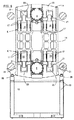
複数の図面は、2つの実施形態でプラスチックならびに粉状物質、金属物質またはセラミック物質のような他の可塑化可能な物質を加工するための射出成形機を示す。この射出成形機は射出成形機では通常のように、機械脚部13上にある型締ユニットFと図示されない射出成形ユニットとを有する。(2つの)型支持体の間、すなわち定置の型支持体12と可動の型支持体11との間には、複数の部分からなる少なくとも1つの射出成形型10を収容することができる。別個の駆動ユニットAを介して個別に駆動可能な2つのトグルレバー機構Kを備える少なくとも1つのトグルレバーペアが、型支持体を射出成形型10が互いに型締めに至るまで順次運動させ、(型)閉鎖方向s−sで射出成形型10を開放するため互いに離れる開放運動をさせるために設けられている。トグルレバー機構K(複数)は支承プレート14,14’に支承されている。とりわけ図2乃至4および6から分かるように、駆動ユニット(複数)は支承プレート14,14’に支承されており、これら支承プレートは閉鎖運動および開放運動の際閉鎖方向に運動する。支承プレートには図4からよく分かるように支承箇所(枢支点、複数)23が設けられており、これらの支承箇所には少なくとも2つのトグルレバー機構Kのための作動エレメントが支承されている。基本的に同様の構成をトグルレバー機構Kが2つより多くあるときでも設けることができる。
The drawings show a plastic and powdery material, an injection molding machine for processing other plasticizable materials such as metal materials, or ceramic materials in the two embodiments. As usual in an injection molding machine, this injection molding machine has a mold clamping unit F on a
図2によればトグルレバー機構Kの一方の端部は型支持体、本実施形態では可動の型支持体11に枢支(関節状に枢動自在に支承)されており、他方の端部は支持エレメント15に支承されている。ここで支承プレート14は、前記型支持体と前記支持エレメントとの間に配置されている。基本的に、少なくとも2つのトグルレバー機構が定置の型支持体に支承されている構成も考えられる。これはたとえば特許文献3に示されている。しかしそれとの相違は、ここでは支承プレートが型支持体と支持エレメントとの間に存在することである。
According to FIG. 2, one end of the toggle lever mechanism K is pivotally supported (movably supported in an articulated manner) on the mold support, in this embodiment the movable mold support 11, and the other end. Is supported on a
図4は図2に関連して駆動ユニットAがどのように支承されているかを示す。一方ではベアリング30が、駆動ユニットAを支承プレート14に支承するために設けられている。駆動ユニットは本実施形態ではスピンドル機構が配設された電気サーボモータであり、任意の構造形式のねじスピンドルないしロールスピンドルを有する。この駆動ユニットには、支承(ベアリング)領域に冷却チャネル29による冷却部(ないし冷却手段)が、または図6[8]では冷却ジャケット33が設けられている。しかし電気サーボ駆動ユニットの代わりに、駆動機構の支承が同じように行われる場合には液圧式駆動ユニットを使用することもできる。ここではトグルレバー機構の配置によって保証された型締ユニットの短い構造形態も明らかである。
FIG. 4 shows how the drive unit A is supported in connection with FIG. On the one hand, a
図1から5の第1実施形態では、駆動ユニットは一方の端部が支承プレート14に支承されており、一方、所属の駆動機構、すなわち本実施形態ではスピンドル機構の他方の端部が支持エレメント15に支承されており、この支持エレメント15にはトグルレバー機構Kも本実施形態では支承されている。この配置は図6から8の実施形態では逆である。すなわち、駆動モータが図6では支持エレメント15’に支承されており、一方、ナット25が支承プレート14’に支承されている。2つの実施形態において、支承プレート14,14’の案内(部)は、共に型閉鎖方向(型締の方向)s−sにおいて、一方では織機脚部13に、一方では力伝達エレメント27に配されているが、2つの案内を組み合わせることが可能であり、または射出成形機の別の箇所で閉鎖方向s−sに案内することも可能である。
In the first embodiment of FIGS. 1 to 5, one end of the drive unit is supported by a
図2には、一方でスピンドル24が図示され、他方でナット25のための支承部も図示されている。スピンドル24の回転によりスピンドルは開放運動の際に、すなわち図2の図示状態から図3の図示状態に移行する際に支承プレート14とともに図で左に移動するから、ナット25の領域には収容ハウジング32が設けられており、この収容ハウジングの中にスピンドル24が潜り込むことができる。スピンドル24は、支承プレートに支承された駆動ユニットAにより駆動され、一方、ナット25は支持エレメント15に回動不能に支承されている。基本的にこの原理を逆にすることも可能である。すなわちナットが回転し、スピドルを回動不能に支承することもできる。このためにたとえば公知の中空シャフトモータを使用することができる。
FIG. 2 shows the
トグルレバー機構Kは、両方の実施形態で5点(5関節)トグルレバーである。その点で(関節状に駆動)、それぞれのトグルレバー機構Kの2つのトグルレバー16の一方にはリンクレバー21が(関節状に)枢動自在に(gelenkig)支承(枢支)されており、トグルレバーの他方の端部は支承箇所(枢支点)23で支承プレート14,14’に連結されている。この支承箇所(枢支点)23は閉鎖運動および開放運動の際に、図2と3の比較から分かるように閉鎖方向s−sに運動する。しかしこの運動によりリンクレバー21は旋回し、これによりトグルレバーは図3の位置から図2の伸展状態に移行する。伸展状態では、2つのトグルレバー16,17が実質的に閉鎖方向s−sに伸びており、トグルレバー関節18は支持エレメント15にある連結点19および可動の型支持体11にある連結点20とほぼ一直線であり、この直線は閉鎖方向s−sに対して平行である。図3の位置で、好ましくは互いに上下(垂直)方向(s−sに対し直交方向)に配置されたトグルレバー機構のトグルレバー16,17は、射出成形型10の開放運動の際に、内側にあるその伸展位置から外方に向かって運動する。この運動経過の態様は、型締ユニット全体の短い構造形態に寄与する。
The toggle lever mechanism K is a five-point (five joints) toggle lever in both embodiments. In that respect (linked drive), one of the two
トグルレバー機構にとって重要な伸展状態を取るために、支持エレメント15,15’には型レベル調整装置26が設けられている。ここで型レベル(高さ)とは、可動の型支持体11と定置の型支持体12との間で型締めされる際の射出成形型10の高さであると理解される。すなわち型締めの際の両型支持体間の間隔(ないしスペース)である。この間隔に応じて支持エレメント15は閉鎖方向s−sに型レベル調整装置26によって運動し、効率的でエネルギーを節約した型締めが最強の力で達成される。支持エレメント15,15’自体は、力伝達エレメントを介して定置の型支持体12と接続している。力伝達エレメントとして本実施形態では横木ロッド27が使用されるが、基本的に型締め空間の周囲で力を伝達する力伝達エレメントを使用することができ、したがってこの空間は型支持体の間でほぼ自由にアクセスされる。これに関して従来技術では、湾曲(ないしC形 buegelartig)のエレメントが公知である。
A mold
支承プレート14は機械脚部13で案内部28に支承されている。ここでは支承プレートの案内によって開放と閉鎖との間の交互動作で精度が影響を受ける。このために図5によれば支承部(Lager)31が設けられており、この支承部は支承プレート14を案内部28上に支承する。支承部31は、横木ロッド(Holme)27が案内部として用いられるように構成することもできる。支承プレートは図4に示すように、その駆動部とともに独立の構成ユニットとして前もって完全に組み立てておき、機械に組み込むことができる。これにより、この構成ユニットの機能性のテストを、他の射出成形機部分と結合(組付け)する前に行うことができる。
The
支承プレートは好ましくはワンピース(一体部材)に構成されており、その限りでマルチ機能部材である。支承プレートは、所属の支承部またはスピンドル24とともに駆動ユニットAを収容するために用いられるだけでなく、この支承プレートはトグルレバー固定部用の支承箇所23を同様に有しており、機械脚部13にある支承プレート14の案内部28も有する。好ましくは冷却チャネル29のような冷却装置も支承プレートに設けられる。または第2実施形態では、スピンドル24のベアリング用の冷却ジャケット33、またはナット25を直接冷却するための冷却ジャケット33が設けられている。これにより幾何学的精度と射出成形機の寿命との両方が向上する。冷却装置は支承プレート14,14’に、とりわけ駆動ユニットA,A’の接続点に設けられている。2つの駆動ユニットを冷却または温度調整することにより同じ温度であることが保証される。したがって温度は線膨張に関係なく同様に同じであり、このことはシステム全体の精度をさらに向上させる。
The support plate is preferably constructed in one piece (integral member) and to the extent it is a multi-functional member. The bearing plate is not only used for housing the drive unit A together with the associated bearing or
支承プレート14,14’の位置は工具(型)の運動のための基準尺度として用いられる。なぜならこの位置において(力)変換関係(Uebersetzungsverhaeltnis)が、とりわけ型締めの際にもっとも正確だからである。これにより型支持体の平行度、ひいては射出成形型の一部が静止状態でも調整される。静止状態でも動的状態でも、すなわち型締め運動の際に、所望の平行度を達成するためにたとえば対応する距離(ないしストローク)測定センサによりサーボモータの制御を行うことができる。ここでは支承プレート14,14’のストローク経過は、型締め運動の開始時には可動の型支持体11の運動とほぼ同じであるが、しかし型締め状態に接近すると支承プレート14は相変わらず運動するが、可動の型支持体はほとんど運動をしなくなる。
The position of the
図6から8の実施形態では、一方では第1実施形態に対してモータとナット25の配置が入れ替えられている。加えて図8の駆動ユニットA’は、支承プレートから取り外し可能な駆動モジュールを形成し、この駆動モジュールは冷却ジャケットも含めて実質的にモータ、ベアリング、ナット25およびスピンドル24を構造的ユニットとして含む。このことの利点は、たとえば駆動ユニットを交換する場合である。なぜなら新しいユニットを前もって検査された完璧なユニットとして使用することができるからである。
In the embodiment of FIGS. 6 to 8, on the other hand, the arrangement of the motor and the
図7では第2実施形態の支承プレート14’が格子状ラーメン構造に構成されている。ここでトグルレバー機構Kは、横木ロッドとして構成された力伝達エレメント(複数)の内部(間)に配置されており、この力伝達エレメントは支承部31’を介する案内部として支承プレート14’のために用いられる。これにより中心軸に対してトグルレバー機構を内側において互いに比較的離して配置することができ、このことは一方では発生するする力を容易に受け止め(ないし吸収し)、かつこの力を支承プレート14’の僅かなたわみをもって作用させることができることに寄与する。他方ではこのことは同時にラーメン構造としての支承プレート14’の開放した構造を必要とし、支承プレートは型締ユニットへのアクセスを同時に容易にする。
In FIG. 7, the
本発明の上記各態様に対し、従属請求項に実質的に等価の範囲において種々の修正、変更および適合化をなし得ることは自明である。 Obviously, various modifications, changes and adaptations may be made to the above aspects of the invention within the scope substantially equivalent to the dependent claims.
10 射出成形型
11 可動の型支持体
12 定置の型支持体
13 機械脚部
14,14’ 支承プレート
15,15’ 支持エレメント
16,17 トグルレバー
18 トグルレバー関節
19,20 連結点
21 リンクレバー
22 21の連結点
23 支承箇所(枢支点)
24 スピンドル
25 ナット
26 型レベル(高さ)調整装置
27 横木ロッド(タイロッド)
28 案内部
29 冷却チャネル
30,30’ 駆動ユニットA用のベアリング
31,31’ 支承プレート14用の支承部
32 収容ハウジング
33 冷却ジャケット(冷却装置)
A,A’ 駆動ユニット
F 型締ユニット
K トグルレバー機構
s−s 閉鎖方向(型締め方向)(中心軸)
DESCRIPTION OF
24
28
A, A 'Drive unit F Clamping unit K Toggle lever mechanism s-s Closing direction (Clamping direction) (Center axis)
Claims (9)
・定置の型支持体(12)と可動の型支持体(11)との間に収容可能な少なくとも1つの射出成形型(10)と、
・互いに独立して各駆動ユニット(A;A’)により駆動可能な2つのトグルレバー機構(K)を備える少なくとも1つのトグルレバーペアと、
・発生する力を受け止める力伝達エレメント(27)とを有し、該力伝達エレメントは、前記定置の型支持体(12)を支持エレメント(15;15’)と接続し、
・前記トグルレバー機構(K)は、可動の支承プレート(14;14’)に支承されており、
前記支承プレート(14;14’)は、前記射出成形機において、複数の力伝達エレメント(27)に可動に支承されており、
前記複数の駆動ユニット(A;A’)は、可動の前記支承プレート(14;14’)に支承されており、前記支承プレートには、少なくとも2つのトグルレバー機構(K)のための作動エレメントが支承されていること、
前記支承プレート(14;14’)の案内部として働く複数の力伝達エレメント(27)が、互いに対称的に中心軸に関し対向して配されること、そして
全ての前記駆動ユニット(A;A’)が、可動の前記支承プレート(14;14’)に、前記力伝達エレメント(27)から離隔して支承されていること、
を特徴とする射出成形機。 A injection molding machine for processing a plasticizing material capable, has a mechanical leg disposed (13) a clamping unit (F), the mold clamping unit,
At least one injection mold (10) that can be accommodated between a stationary mold support (12) and a movable mold support (11);
At least one toggle lever pair comprising two toggle lever mechanisms (K) that can be driven by each drive unit (A; A ′) independently of each other;
A force transmission element (27) for receiving the generated force, the force transmission element connecting the stationary mold support (12) with the support element (15; 15 ');
The toggle lever mechanism (K) is supported by a movable support plate (14; 14 '),
The support plate (14; 14 ') is movably supported by a plurality of force transmission elements (27) in the injection molding machine,
The plurality of drive units (A; A ′) are supported on the movable support plate (14; 14 ′), and the support plate has an actuating element for at least two toggle lever mechanisms (K). Is supported,
A plurality of force transmission elements (27) acting as guides for the bearing plate (14; 14 ') are arranged symmetrically opposite each other with respect to the central axis, and all the drive units (A; A') ) Is supported on the movable bearing plate (14; 14 ′) away from the force transmitting element (27),
An injection molding machine characterized by
前記支承プレート(14;14’)は、前記型支持体と前記支持エレメントとの間に配置されている、ことを特徴とする請求項1に記載の射出成形機。 Wherein one end of the toggle lever mechanism (K) is pivotally supported by the mold support, the other end supporting element; are supported on (15 15 '),
It said support plate (14; 14 ') is an injection molding machine according to claim 1, characterized in that is disposed between the support element and the mold support.
スピンドル(24)またはナット(25)が、前記支承プレート(14)に支承された駆動ユニット(A)によって駆動され、一方、ナット(25)またはスピンドル(24)は前記支持エレメント(15)に回動不能に支承されている、ことを特徴とする請求項1から3までのいずれか一項に記載の射出成形機。 It said drive unit (A) is an electric servo motor for driving the spindle mechanism,
A spindle (24) or nut (25) is driven by a drive unit (A) supported on the bearing plate (14), while the nut (25) or spindle (24) is turned on the support element (15). The injection molding machine according to any one of claims 1 to 3, wherein the injection molding machine is immovably supported.
前記トグルレバー機構(K)は、横木ロッドとして構成された力伝達エレメントの内側に配置されている、ことを特徴とする請求項1から6までのいずれか一項に記載の射出成形機。 The support plate (14 ') is configured in a lattice ramen structure,
It said toggle lever mechanism (K) is an injection molding machine according to any one of are arranged inside the force transmission element is configured as rungs rod, claim 1, characterized in that up to 6.
Applications Claiming Priority (3)
| Application Number | Priority Date | Filing Date | Title |
|---|---|---|---|
| DE102010048560A DE102010048560B3 (en) | 2010-10-18 | 2010-10-18 | Injection molding machine with at least two toggle mechanisms |
| DE102010048560.8 | 2010-10-18 | ||
| PCT/EP2011/005190 WO2012052138A1 (en) | 2010-10-18 | 2011-10-16 | Injection-moulding machine having at least two toggle lever mechanisms |
Publications (3)
| Publication Number | Publication Date |
|---|---|
| JP2013540620A JP2013540620A (en) | 2013-11-07 |
| JP2013540620A5 JP2013540620A5 (en) | 2014-11-20 |
| JP5826855B2 true JP5826855B2 (en) | 2015-12-02 |
Family
ID=44907789
Family Applications (1)
| Application Number | Title | Priority Date | Filing Date |
|---|---|---|---|
| JP2013533130A Active JP5826855B2 (en) | 2010-10-18 | 2011-10-16 | Injection molding machine having at least two toggle lever mechanisms |
Country Status (6)
| Country | Link |
|---|---|
| US (1) | US8821152B2 (en) |
| EP (1) | EP2629954B1 (en) |
| JP (1) | JP5826855B2 (en) |
| CA (1) | CA2814890C (en) |
| DE (1) | DE102010048560B3 (en) |
| WO (1) | WO2012052138A1 (en) |
Families Citing this family (11)
| Publication number | Priority date | Publication date | Assignee | Title |
|---|---|---|---|---|
| DE102013013738A1 (en) * | 2013-08-21 | 2015-02-26 | Ferromatik Milacron Gmbh | injection molding machine |
| WO2016108202A1 (en) | 2014-12-31 | 2016-07-07 | Sandretto S.P.A. | Improved toggle press for an injection moulding machine |
| ITUB20169997A1 (en) * | 2016-01-14 | 2017-07-14 | Negri Bossi Spa | KNEEPAD CLOSING GROUP FOR INJECTION PRESS |
| DE102016119581A1 (en) * | 2016-10-13 | 2018-04-19 | Arburg Gmbh + Co. Kg | Mold closing unit with thermal management |
| DE102016119583B3 (en) * | 2016-10-13 | 2018-01-04 | Arburg Gmbh + Co. Kg | Method and device for encapsulating a load receiving a mold clamping unit of an injection molding machine |
| CN108312455A (en) * | 2017-12-07 | 2018-07-24 | 海天塑机集团有限公司 | A kind of method of controlling security and system of electric injection molding machine crank type clasp mould mechanism |
| DE102018124608A1 (en) * | 2018-10-05 | 2020-04-09 | Arburg Gmbh + Co Kg | Mold clamping unit for an injection molding machine and method for locking a force transmission element |
| CN112936715A (en) * | 2021-01-27 | 2021-06-11 | 李俊 | A penetrate gluey part for injection molding machine |
| WO2022217499A1 (en) * | 2021-04-14 | 2022-10-20 | 吉利汽车集团有限公司 | Horizontal die-casting machine |
| AT524560B1 (en) | 2021-06-11 | 2022-07-15 | Engel Austria Gmbh | Clamping unit for a molding machine and molding machine with such |
| US11931939B1 (en) * | 2022-10-25 | 2024-03-19 | Haw Chan Tan | Toggle mechanism for closing of a mold in a molding machine |
Family Cites Families (14)
| Publication number | Priority date | Publication date | Assignee | Title |
|---|---|---|---|---|
| FR1364693A (en) | 1963-05-13 | 1964-06-26 | Advanced injection molding machine | |
| JPS6287813A (en) | 1985-10-14 | 1987-04-22 | Mitsubishi Cable Ind Ltd | Two-wavelength system optical sensor utilizing optical fiber |
| JPS6287813U (en) | 1985-11-21 | 1987-06-04 | ||
| JP2584287B2 (en) * | 1988-08-29 | 1997-02-26 | ファナック株式会社 | Toggle type mold clamping device |
| IT1249177B (en) * | 1991-04-22 | 1995-02-18 | Bmb Spa | MOLD CLOSING GROUP IN MACHINES FOR MOLDING OF PLASTIC MATERIALS OR FOR DOUBLE KNEE DIE CASTING |
| JP3366838B2 (en) * | 1997-08-29 | 2003-01-14 | 東芝機械株式会社 | Mold clamping device of injection molding machine |
| DE19923849C2 (en) * | 1999-05-25 | 2003-04-03 | Karl Hehl | Mold clamping unit for an injection molding machine |
| DE19957485A1 (en) * | 1999-11-23 | 2001-05-31 | Mannesmann Ag | Closure and clamping system for an injection molding machine has a linear motor connected to a load transfer member and moving platen via levers |
| TW454686U (en) * | 1999-12-21 | 2001-09-11 | Ind Tech Res Inst | Mold locking device for an injection molding machine |
| US6520766B2 (en) | 2000-12-06 | 2003-02-18 | Hwa Chin Machinery Factory Co., Ltd. | Mold locking device for a molding machine |
| DE20120612U1 (en) | 2001-12-20 | 2002-02-28 | Cyclus Engineering Gmbh | Mold clamping device |
| JP3620724B2 (en) * | 2002-06-04 | 2005-02-16 | 株式会社日本製鋼所 | Molding device for electric injection molding machine |
| DE102006054072A1 (en) | 2006-11-16 | 2008-05-21 | Hwa Chin Machinery Factory Co., Ltd., Yung-Kang | Device for opening and closing a molding tool of an injection molding machine comprises two sliding rails extending parallel to each other and holding moving a molding plate and an operating plate |
| DE102006061969B4 (en) * | 2006-12-21 | 2009-12-17 | Karl Hehl | Method for operating an injection molding machine with two toggle mechanisms |
-
2010
- 2010-10-18 DE DE102010048560A patent/DE102010048560B3/en not_active Expired - Fee Related
-
2011
- 2011-10-16 EP EP11772890.7A patent/EP2629954B1/en active Active
- 2011-10-16 US US13/880,129 patent/US8821152B2/en active Active
- 2011-10-16 JP JP2013533130A patent/JP5826855B2/en active Active
- 2011-10-16 CA CA2814890A patent/CA2814890C/en active Active
- 2011-10-16 WO PCT/EP2011/005190 patent/WO2012052138A1/en active Application Filing
Also Published As
| Publication number | Publication date |
|---|---|
| US8821152B2 (en) | 2014-09-02 |
| CA2814890C (en) | 2018-11-20 |
| EP2629954B1 (en) | 2014-08-06 |
| DE102010048560B3 (en) | 2012-03-15 |
| CA2814890A1 (en) | 2012-04-26 |
| JP2013540620A (en) | 2013-11-07 |
| US20130224329A1 (en) | 2013-08-29 |
| WO2012052138A1 (en) | 2012-04-26 |
| EP2629954A1 (en) | 2013-08-28 |
Similar Documents
| Publication | Publication Date | Title |
|---|---|---|
| JP5826855B2 (en) | Injection molding machine having at least two toggle lever mechanisms | |
| JP5401079B2 (en) | Injection molding machine | |
| JP5492538B2 (en) | Injection molding machine | |
| JP2013540620A5 (en) | ||
| JP6184908B2 (en) | Opening and closing device and molding device | |
| US9358711B2 (en) | Apparatus for injection molding | |
| CN107107426A (en) | Opening/closing and shaped device | |
| JP2018167453A (en) | Injection molding machine | |
| JP2014141070A (en) | Injection molding machine | |
| CN103302820B (en) | Injection machine | |
| EP2261001B1 (en) | Vertical microinjection machine | |
| KR20040017861A (en) | Injection device and injection method | |
| US8758000B2 (en) | Apparatus for moulding plastic micro-pieces by ultrasound | |
| JP5064186B2 (en) | Injection molding machine | |
| JP5743972B2 (en) | Toggle type small mold clamping device | |
| JP6591774B2 (en) | Drive device for valve pin in injection mold | |
| JP2017202649A (en) | Device for driving valve pin in injection molding die | |
| JPH11286020A (en) | Mold clamping device of mold for producing article formed of thermoplastic resin | |
| CN103057074A (en) | Injection molding machine | |
| JP2014046486A (en) | Mold clamping device for injection molding machines | |
| JP6035151B2 (en) | Method of calculating moment of inertia and mold clamping device | |
| JP4875629B2 (en) | Injection molding equipment for plastic processing | |
| JP3813593B2 (en) | Toggle mold clamping device | |
| KR101160562B1 (en) | Vertical-type electric injection molding machine | |
| JP4901965B2 (en) | Fully electric molding machine |
Legal Events
| Date | Code | Title | Description |
|---|---|---|---|
| A521 | Request for written amendment filed |
Free format text: JAPANESE INTERMEDIATE CODE: A523 Effective date: 20130311 |
|
| A529 | Written submission of copy of amendment under article 34 pct |
Free format text: JAPANESE INTERMEDIATE CODE: A529 Effective date: 20130308 |
|
| A521 | Request for written amendment filed |
Free format text: JAPANESE INTERMEDIATE CODE: A523 Effective date: 20141002 |
|
| A621 | Written request for application examination |
Free format text: JAPANESE INTERMEDIATE CODE: A621 Effective date: 20141002 |
|
| A977 | Report on retrieval |
Free format text: JAPANESE INTERMEDIATE CODE: A971007 Effective date: 20150415 |
|
| A131 | Notification of reasons for refusal |
Free format text: JAPANESE INTERMEDIATE CODE: A131 Effective date: 20150421 |
|
| A521 | Request for written amendment filed |
Free format text: JAPANESE INTERMEDIATE CODE: A523 Effective date: 20150619 |
|
| A131 | Notification of reasons for refusal |
Free format text: JAPANESE INTERMEDIATE CODE: A131 Effective date: 20150915 |
|
| A521 | Request for written amendment filed |
Free format text: JAPANESE INTERMEDIATE CODE: A523 Effective date: 20150916 |
|
| TRDD | Decision of grant or rejection written | ||
| A01 | Written decision to grant a patent or to grant a registration (utility model) |
Free format text: JAPANESE INTERMEDIATE CODE: A01 Effective date: 20151013 |
|
| A61 | First payment of annual fees (during grant procedure) |
Free format text: JAPANESE INTERMEDIATE CODE: A61 Effective date: 20151014 |
|
| R150 | Certificate of patent or registration of utility model |
Ref document number: 5826855 Country of ref document: JP Free format text: JAPANESE INTERMEDIATE CODE: R150 |
|
| R250 | Receipt of annual fees |
Free format text: JAPANESE INTERMEDIATE CODE: R250 |
|
| R250 | Receipt of annual fees |
Free format text: JAPANESE INTERMEDIATE CODE: R250 |
|
| R250 | Receipt of annual fees |
Free format text: JAPANESE INTERMEDIATE CODE: R250 |
|
| R250 | Receipt of annual fees |
Free format text: JAPANESE INTERMEDIATE CODE: R250 |
|
| R250 | Receipt of annual fees |
Free format text: JAPANESE INTERMEDIATE CODE: R250 |
|
| R250 | Receipt of annual fees |
Free format text: JAPANESE INTERMEDIATE CODE: R250 |