JP5826189B2 - Direct injection diesel engine - Google Patents
Direct injection diesel engine Download PDFInfo
- Publication number
- JP5826189B2 JP5826189B2 JP2012550506A JP2012550506A JP5826189B2 JP 5826189 B2 JP5826189 B2 JP 5826189B2 JP 2012550506 A JP2012550506 A JP 2012550506A JP 2012550506 A JP2012550506 A JP 2012550506A JP 5826189 B2 JP5826189 B2 JP 5826189B2
- Authority
- JP
- Japan
- Prior art keywords
- piston
- diameter
- recess
- cylinder
- fuel
- Prior art date
- Legal status (The legal status is an assumption and is not a legal conclusion. Google has not performed a legal analysis and makes no representation as to the accuracy of the status listed.)
- Active
Links
- 238000002347 injection Methods 0.000 title claims description 23
- 239000007924 injection Substances 0.000 title claims description 23
- 239000000446 fuel Substances 0.000 claims description 60
- 238000002485 combustion reaction Methods 0.000 claims description 43
- 239000000203 mixture Substances 0.000 description 15
- 239000002245 particle Substances 0.000 description 11
- 239000004071 soot Substances 0.000 description 11
- 239000003921 oil Substances 0.000 description 10
- 239000013618 particulate matter Substances 0.000 description 8
- 229930195733 hydrocarbon Natural products 0.000 description 5
- 150000002430 hydrocarbons Chemical class 0.000 description 5
- 239000003344 environmental pollutant Substances 0.000 description 3
- MWUXSHHQAYIFBG-UHFFFAOYSA-N nitrogen oxide Inorganic materials O=[N] MWUXSHHQAYIFBG-UHFFFAOYSA-N 0.000 description 3
- 231100000719 pollutant Toxicity 0.000 description 3
- 238000010790 dilution Methods 0.000 description 2
- 239000012895 dilution Substances 0.000 description 2
- 238000001914 filtration Methods 0.000 description 2
- 238000012423 maintenance Methods 0.000 description 2
- 239000004215 Carbon black (E152) Substances 0.000 description 1
- 239000003054 catalyst Substances 0.000 description 1
- 238000011109 contamination Methods 0.000 description 1
- 239000007789 gas Substances 0.000 description 1
- 238000007373 indentation Methods 0.000 description 1
- 230000003993 interaction Effects 0.000 description 1
- 230000007774 longterm Effects 0.000 description 1
- 239000000314 lubricant Substances 0.000 description 1
- 239000010687 lubricating oil Substances 0.000 description 1
- 239000010705 motor oil Substances 0.000 description 1
- 238000005457 optimization Methods 0.000 description 1
- 238000012805 post-processing Methods 0.000 description 1
- 238000010791 quenching Methods 0.000 description 1
- 230000000171 quenching effect Effects 0.000 description 1
- 238000000926 separation method Methods 0.000 description 1
- 238000004904 shortening Methods 0.000 description 1
- 239000007921 spray Substances 0.000 description 1
- 238000009834 vaporization Methods 0.000 description 1
- 230000008016 vaporization Effects 0.000 description 1
Images

Classifications
-
- F—MECHANICAL ENGINEERING; LIGHTING; HEATING; WEAPONS; BLASTING
- F02—COMBUSTION ENGINES; HOT-GAS OR COMBUSTION-PRODUCT ENGINE PLANTS
- F02B—INTERNAL-COMBUSTION PISTON ENGINES; COMBUSTION ENGINES IN GENERAL
- F02B23/00—Other engines characterised by special shape or construction of combustion chambers to improve operation
- F02B23/02—Other engines characterised by special shape or construction of combustion chambers to improve operation with compression ignition
- F02B23/06—Other engines characterised by special shape or construction of combustion chambers to improve operation with compression ignition the combustion space being arranged in working piston
- F02B23/0672—Omega-piston bowl, i.e. the combustion space having a central projection pointing towards the cylinder head and the surrounding wall being inclined towards the cylinder center axis
-
- F—MECHANICAL ENGINEERING; LIGHTING; HEATING; WEAPONS; BLASTING
- F02—COMBUSTION ENGINES; HOT-GAS OR COMBUSTION-PRODUCT ENGINE PLANTS
- F02B—INTERNAL-COMBUSTION PISTON ENGINES; COMBUSTION ENGINES IN GENERAL
- F02B23/00—Other engines characterised by special shape or construction of combustion chambers to improve operation
- F02B23/02—Other engines characterised by special shape or construction of combustion chambers to improve operation with compression ignition
- F02B23/06—Other engines characterised by special shape or construction of combustion chambers to improve operation with compression ignition the combustion space being arranged in working piston
- F02B23/0645—Details related to the fuel injector or the fuel spray
- F02B23/0669—Details related to the fuel injector or the fuel spray having multiple fuel spray jets per injector nozzle
-
- F—MECHANICAL ENGINEERING; LIGHTING; HEATING; WEAPONS; BLASTING
- F02—COMBUSTION ENGINES; HOT-GAS OR COMBUSTION-PRODUCT ENGINE PLANTS
- F02B—INTERNAL-COMBUSTION PISTON ENGINES; COMBUSTION ENGINES IN GENERAL
- F02B23/00—Other engines characterised by special shape or construction of combustion chambers to improve operation
- F02B23/02—Other engines characterised by special shape or construction of combustion chambers to improve operation with compression ignition
- F02B23/06—Other engines characterised by special shape or construction of combustion chambers to improve operation with compression ignition the combustion space being arranged in working piston
- F02B23/0678—Unconventional, complex or non-rotationally symmetrical shapes of the combustion space, e.g. flower like, having special shapes related to the orientation of the fuel spray jets
- F02B23/0693—Unconventional, complex or non-rotationally symmetrical shapes of the combustion space, e.g. flower like, having special shapes related to the orientation of the fuel spray jets the combustion space consisting of step-wise widened multiple zones of different depth
-
- F—MECHANICAL ENGINEERING; LIGHTING; HEATING; WEAPONS; BLASTING
- F02—COMBUSTION ENGINES; HOT-GAS OR COMBUSTION-PRODUCT ENGINE PLANTS
- F02B—INTERNAL-COMBUSTION PISTON ENGINES; COMBUSTION ENGINES IN GENERAL
- F02B3/00—Engines characterised by air compression and subsequent fuel addition
- F02B3/06—Engines characterised by air compression and subsequent fuel addition with compression ignition
-
- F—MECHANICAL ENGINEERING; LIGHTING; HEATING; WEAPONS; BLASTING
- F02—COMBUSTION ENGINES; HOT-GAS OR COMBUSTION-PRODUCT ENGINE PLANTS
- F02F—CYLINDERS, PISTONS OR CASINGS, FOR COMBUSTION ENGINES; ARRANGEMENTS OF SEALINGS IN COMBUSTION ENGINES
- F02F3/00—Pistons
- F02F3/0015—Multi-part pistons
-
- F—MECHANICAL ENGINEERING; LIGHTING; HEATING; WEAPONS; BLASTING
- F02—COMBUSTION ENGINES; HOT-GAS OR COMBUSTION-PRODUCT ENGINE PLANTS
- F02F—CYLINDERS, PISTONS OR CASINGS, FOR COMBUSTION ENGINES; ARRANGEMENTS OF SEALINGS IN COMBUSTION ENGINES
- F02F3/00—Pistons
- F02F3/26—Pistons having combustion chamber in piston head
-
- F—MECHANICAL ENGINEERING; LIGHTING; HEATING; WEAPONS; BLASTING
- F02—COMBUSTION ENGINES; HOT-GAS OR COMBUSTION-PRODUCT ENGINE PLANTS
- F02B—INTERNAL-COMBUSTION PISTON ENGINES; COMBUSTION ENGINES IN GENERAL
- F02B2275/00—Other engines, components or details, not provided for in other groups of this subclass
- F02B2275/14—Direct injection into combustion chamber
-
- Y—GENERAL TAGGING OF NEW TECHNOLOGICAL DEVELOPMENTS; GENERAL TAGGING OF CROSS-SECTIONAL TECHNOLOGIES SPANNING OVER SEVERAL SECTIONS OF THE IPC; TECHNICAL SUBJECTS COVERED BY FORMER USPC CROSS-REFERENCE ART COLLECTIONS [XRACs] AND DIGESTS
- Y02—TECHNOLOGIES OR APPLICATIONS FOR MITIGATION OR ADAPTATION AGAINST CLIMATE CHANGE
- Y02T—CLIMATE CHANGE MITIGATION TECHNOLOGIES RELATED TO TRANSPORTATION
- Y02T10/00—Road transport of goods or passengers
- Y02T10/10—Internal combustion engine [ICE] based vehicles
- Y02T10/12—Improving ICE efficiencies
Landscapes
- Engineering & Computer Science (AREA)
- Chemical & Material Sciences (AREA)
- Combustion & Propulsion (AREA)
- Mechanical Engineering (AREA)
- General Engineering & Computer Science (AREA)
- Combustion Methods Of Internal-Combustion Engines (AREA)
- Cylinder Crankcases Of Internal Combustion Engines (AREA)
Description
本発明は、シリンダごとに4つのバルブ、すなわち2つの吸気バルブおよび2つの排気バルブを備えている形式の直噴ディーゼルエンジンに関する。 The present invention relates to a direct injection diesel engine of the type comprising four valves per cylinder, i.e. two intake valves and two exhaust valves.
ディーゼルエンジンを設計するときの最も重要な考慮事項の1つは、排出物(特に、燃え残りの炭化水素、窒素酸化物(NOx)、およびすす状の粒子状物質)のレベルであり、ますます厳しくなる排出物の規制が、エンジンの排出物を可能な限り最も費用対効果に優れたやり方で削減するためのさらなる努力へと、エンジンの開発者を駆り立てている。この点に関し、一般的には、触媒およびろ過システムなどの排気ガス事後処理システムに関する初期コストおよびランニングコストの両方を回避するために、エンジンそのものに基づく手段に注力することが好ましい。 One of the most important considerations when designing a diesel engine is the level of emissions, especially unburned hydrocarbons, nitrogen oxides (NO x ), and soot-like particulate matter Increasingly stringent emissions regulations are driving engine developers to make further efforts to reduce engine emissions in the most cost-effective way possible. In this regard, it is generally preferable to focus on means based on the engine itself to avoid both the initial and running costs associated with exhaust gas aftertreatment systems such as catalysts and filtration systems.
ディーゼルエンジンにおいては、燃焼室の形状およびその燃料噴射システムとの相互作用が、排出物の削減において決定的に重要である。直噴ディーゼルエンジンの燃焼室は、一般に、ピストンの頂部に位置している。シリンダごとに2つのバルブ(すなわち、1つの吸気バルブおよび1つの排気バルブ)を有するエンジンにおいては、必然的に、燃料インジェクタがシリンダおよびピストンの軸からオフセットされ、シリンダおよびピストンの軸に対して傾けられており、このことは、ピストンの頂部の燃焼室も、燃料インジェクタのおおむね下方に位置するように同様にオフセットされなければならないことを意味している。そのようなオフセットされた燃焼室は、燃焼室における燃料/空気混合物の渦運動がシリンダの軸を中心にして一様でなく、燃料インジェクタの種々の噴射オリフィスからの燃料の噴霧経路の長さがおおむね等しくないという事実ゆえに、エンジンの排出物および燃料経済性の両方について悪影響を有する。この理由で、シリンダごとに4つのバルブを有する直噴ディーゼルエンジンが、一般的には好ましい。なぜならば、燃焼室を同軸に配置することができ、燃料インジェクタも同軸に配置し、同軸に向けることができるからである。 In diesel engines, the shape of the combustion chamber and its interaction with the fuel injection system is critical in reducing emissions. The combustion chamber of a direct injection diesel engine is generally located at the top of the piston. In an engine with two valves per cylinder (ie, one intake valve and one exhaust valve), the fuel injector is necessarily offset from the cylinder and piston axes and tilted with respect to the cylinder and piston axes. This means that the combustion chamber at the top of the piston must be offset as well so that it is generally below the fuel injector. Such an offset combustion chamber is such that the vortex motion of the fuel / air mixture in the combustion chamber is not uniform about the axis of the cylinder, and the length of the fuel spray path from the various injection orifices of the fuel injector Due to the fact that they are generally not equal, they have a negative impact on both engine emissions and fuel economy. For this reason, direct injection diesel engines with four valves per cylinder are generally preferred. This is because the combustion chamber can be arranged coaxially, and the fuel injector can also be arranged coaxially and can be oriented coaxially.
4バルブの直噴ディーゼルエンジンの燃焼室について、多数のさまざまな形状が知られているが、その一部は、縦断面においておおむねωの形状であり、これが本発明の関係する燃焼室の形状である。より具体的には、本発明は、燃焼室を構成する凹所が、縦断面においてピストンの軸を中心にして回転対称であり、底部と側壁とによって定められており、実質的に円すい形または円すい台形の突起が底部から立ち上がっており、この凹所が、ピストン頂部から最も遠い下部環状体部分と、ピストン頂部に最も近く、ピストン頂部に向かって直径が徐々に増加している上部とを含んでおり、これらの上部および下部が、縦断面においてアーチ形であって前記凹所へと突き出している環状のリップによって隔てられている形式のピストンに関する。 A number of different shapes are known for the combustion chamber of a four-valve direct injection diesel engine, some of which are generally ω in the longitudinal section, which is the shape of the combustion chamber to which the present invention relates. is there. More specifically, according to the present invention, the recess constituting the combustion chamber is rotationally symmetric about the axis of the piston in the longitudinal section and is defined by the bottom and the side wall, and is substantially conical or A frustoconical protrusion rises from the bottom, and this recess includes a lower annulus portion furthest from the piston top and an upper portion closest to the piston top and gradually increasing in diameter toward the piston top. The upper and lower parts of the piston being of arcuate shape in longitudinal section and separated by an annular lip projecting into the recess.
この一般的形式のピストンが、DongFengの中国特許出願第2010745567号に開示されている。しかしながら、このピストンは、2バルブの直噴エンジンにおける使用が意図されており、したがって燃焼室がピストン頂部において偏心して位置しており、これは、いずれにせよ、上述した理由で不都合である。しかしながら、この文献に開示されている燃焼室を、ピストン頂部において中心に配置することで、ピストンを本質的に4バルブのディーゼルエンジンにおける使用に適するようにしても、燃料および空気の混合が充分には完了せず、排出物(例えば、燃え残りの炭化水素、NOx、およびすす状の粒子状物質)のレベルが容認できない高さになると考えられる。 This general type of piston is disclosed in DongFeng's Chinese Patent Application No. 2010745567. However, this piston is intended for use in a two-valve direct-injection engine, so that the combustion chamber is located eccentrically at the top of the piston, which in any case is disadvantageous for the reasons described above. However, the combustion chamber disclosed in this document is centrally located at the top of the piston so that the fuel and air mixing is sufficient even if the piston is essentially suitable for use in a four-valve diesel engine. Will not be completed and the level of emissions (eg, unburned hydrocarbons, NO x , and soot particulate matter) will be unacceptably high.
おおむね同様の形式のさらなるピストンが、米国特許第7210448号明細書および米国特許第6732703号明細書に開示されているが、これらの特許のどちらにおいても、環状のリップが存在せず、したがって凹所の上部と下部との間の識別可能な分割が存在していない。これらの燃焼室においても、空気および燃料の混合が最適にはならないと考えられ、汚染物質の排出のレベルが、やはり望まれるほどには下がらないと考えられる。さらに、燃料/空気混合物がかなりの程度までシリンダの壁面に接触し、結果としてシリンダの壁面の潤滑油が燃料によって希釈されることで、エンジンの寿命が短くなることが明らかになっている。 More pistons of generally similar type are disclosed in US Pat. No. 7,210,448 and US Pat. No. 6,732,703, but in both of these patents there is no annular lip and therefore a recess. There is no discernible division between the top and bottom of the. Even in these combustion chambers, the mixing of air and fuel would not be optimal and the level of pollutant emissions would still not be as low as desired. In addition, it has been found that the fuel / air mixture contacts the cylinder wall to a significant extent, resulting in dilution of the lubricating oil on the cylinder wall with the fuel, thereby shortening the life of the engine.
上述のように、すす状粒子の発生のレベルが、上述のすべての先行文献の燃焼室においては、容認できないほどに高くなると考えられる。これは、燃料の不完全な燃焼を呈し、したがって非効率を呈し、さらには大気へのすす粒子の排出を、ろ過などの高価な事後処理によらなければ、容認できるレベルまたは法的に許されるレベルへと下げることができない。すすまたは部分的に燃焼した炭化水素粒子は、驚くほど硬く、したがって摩耗を引き起こし、実際に、先行文献の燃焼システムにおいて、容認できないほどに高い割合のすす粒子がシリンダの壁面に接触し、この壁面に存在する油の層に捕らえられ、あるいは混入することが明らかになっている。油および混入した粒子は、その後にエンジンの主たる油回路へと戻り、そこで粒子が長期にわたり摩耗によって油ポンプおよび油の供給先の他の部品に大きな損傷を引き起こし、エンジンの保守コストを上昇させ、さらには/あるいはエンジンの寿命を短くする。 As mentioned above, the level of soot-like particles generation is believed to be unacceptably high in all the above-mentioned prior art combustion chambers. This presents an incomplete combustion of the fuel and thus inefficiency, and even soot emissions to the atmosphere are acceptable or legally acceptable without expensive post-processing such as filtration. It cannot be lowered to the level. Soot or partially burned hydrocarbon particles are surprisingly hard and therefore cause wear, and in fact, in the prior art combustion systems, an unacceptably high proportion of soot particles contact the cylinder wall and this wall It has been found that it is trapped or mixed in the oil layer present in The oil and contaminated particles will then return to the main oil circuit of the engine, where the particles will cause significant damage to the oil pump and other parts of the oil supply due to long-term wear, increasing engine maintenance costs, Furthermore, / or shorten the life of the engine.
したがって、本発明の目的は、4バルブの直噴ディーゼルエンジンおよびそのようなエンジンのためのピストンであって、燃料/空気混合物がこれまでよりも強くかつ徹底的に混合されることで、排出物の削減およびエンジンの効率の向上がもたらされるエンジンおよびピストンを提供することにある。本発明のさらなる目的は、生成されるすす状の粒子状物質の量を少なくするだけでなく、それらの粒子状物質がシリンダの壁面の油の層に混入する割合も少なくすることで、エンジンの保守のコストを下げ、寿命を改善することにある。 Accordingly, it is an object of the present invention to provide a four-valve direct injection diesel engine and a piston for such an engine so that the fuel / air mixture is more intensely and thoroughly mixed than before so that emissions are reduced. It is an object of the present invention to provide an engine and a piston capable of reducing the engine efficiency and improving the engine efficiency. A further object of the present invention is not only to reduce the amount of soot-like particulate matter that is produced, but also to reduce the proportion of those particulate matter mixed into the oil layer on the cylinder wall, thereby reducing engine The purpose is to reduce maintenance costs and improve service life.
本発明によれば、4バルブの直噴ディーゼルエンジンのための上述の形式のピストンが、円すい形または円すい台形の突起の挟角が、104°〜108°の間であり、底部からピストンの頂部の平面までの凹所の最大深さが、ピストンの直径の13〜22%の間(好ましくは、18〜22%の間)であり、円すい形または円すい台形の突起が、ピストンの直径の38〜44%の間(好ましくは、38〜42%の間)の直径を有する円形の線に沿って底部と融合し、リップの直径が、ピストンの直径の54〜59%の間であり、リップの最小径の線が、ピストンの頂部の平面からピストンの直径の5〜10%の間の距離だけ離れた位置にあり、凹所の上部の直径が、リップの最小径の線におけるピストンの直径の54〜59%から、凹所の側壁がピストンの頂部の平面と交わる線におけるピストンの直径の72〜76%へと増加していることを特徴とする。 According to the present invention, a piston of the type described above for a four-valve direct injection diesel engine has a conical or frustoconical projection angle between 104 ° and 108 °, and from the bottom to the top of the piston The maximum depth of the recess to the plane of the cylinder is between 13-22% of the piston diameter (preferably between 18-22%), and the conical or frusto-conical protrusions are 38 of the piston diameter. Fusing with the bottom along a circular line having a diameter between ˜44% (preferably between 38 and 42%), the lip diameter being between 54 and 59% of the piston diameter, The smallest diameter line is at a distance of 5-10% of the piston diameter from the top plane of the piston, and the upper diameter of the recess is the diameter of the piston at the smallest diameter line of the lip From 54 to 59% It is characterized by an increase to 72-76% of the piston diameter in a line intersecting the plane of the top of the piston.
燃焼室の多数の寸法パラメータのいずれもが、空気および燃料の混合の強さおよび徹底度に影響を有しており、すなわちエンジンの効率および排出物に影響を有しているため、すべてのパラメータを互いに対して最適化することが必要であり、徹底的な試験を行うことによって、上述の寸法の範囲が最適の範囲を呈し、生じる排出物が大幅に少なく、より高い効率が達成されることを明らかにした。上述の公知の燃焼室に対する最も大きな相違は、環状のリップが大幅に大きく、すなわち燃焼室へとさらに突き出しており、燃焼室の上部および下部へのより顕著な分離をもたらしている点にある。4バルブの直噴ディーゼルエンジンの吸気バルブは、一般に、燃焼室において実質的にシリンダの軸を中心とする流入空気の渦を生じさせるように構成および配置された形式であり、環状のリップがより大きいことで、渦を巻く空気および燃料がリップの下方の燃焼室の下部により長く滞留し、したがって空気および燃料が、燃焼室の上部へと上方に移動し、次いでピストンが上死点位置から遠ざかるように移動した後のシリンダの上部へと移動する前に、より徹底的に混合されると考えられる。また、より大きな環状のリップは、燃焼室の下部から流出する空気/燃料混合物に半径方向内側への運動成分を与え、これはすなわち、比較的低温なシリンダ壁面に衝突する燃焼中の混合物の割合が少なくなることを意味する。これにより、燃料/空気混合物のシリンダ壁面への接触の程度が少なくなり、結果としてシリンダ壁面の潤滑油の燃料による希釈が少なくなる。さらに、より大きな環状のリップは、シリンダ壁面との接触によって消火または急冷される燃焼中の混合物の割合を少なくし、結果としてNOxの発生が少なくなる。空気および燃料のより徹底的な混合が、より完全な燃焼をもたらし、したがって燃え残りの炭化水素(特に、すす状の粒子状物質)の排出を少なくする。このように、生じるすす状の粒子状物質が少なくなるだけでなく、主としてより大きな環状リップの結果として、シリンダ壁面の表面の油の層に混入するすす状の粒子状物質の割合も少なくなる。 All of the numerous dimensional parameters of the combustion chamber have an impact on the strength and thoroughness of the air and fuel mixing, i.e. on the engine efficiency and emissions, so all parameters Must be optimized with respect to each other, and through thorough testing, the above dimensional ranges will be optimal, resulting in significantly less emissions and higher efficiencies being achieved. Was revealed. The biggest difference with the known combustion chamber mentioned above is that the annular lip is significantly larger, i.e. protruding further into the combustion chamber, resulting in a more pronounced separation into the upper and lower portions of the combustion chamber. The intake valve of a four-valve direct injection diesel engine is generally of a type constructed and arranged to create a vortex of incoming air substantially in the combustion chamber about the cylinder axis, with a more annular lip. By being large, the swirling air and fuel stay longer in the lower part of the combustion chamber below the lip, so that the air and fuel move up to the upper part of the combustion chamber and then the piston moves away from the top dead center position. It is believed that the mixture is more thoroughly mixed before moving to the top of the cylinder after moving. Also, the larger annular lip imparts a radially inward motion component to the air / fuel mixture exiting from the lower part of the combustion chamber, that is, the proportion of the combusting mixture impinging on the relatively cool cylinder wall Means less. This reduces the degree of contact of the fuel / air mixture with the cylinder wall, resulting in less dilution of the lubricant on the cylinder wall with the fuel. Furthermore, the larger annular lip reduces the proportion of the burning mixture that is extinguished or quenched by contact with the cylinder wall, resulting in less NO x generation. A more thorough mixing of air and fuel results in a more complete combustion, thus reducing emissions of unburned hydrocarbons (especially soot-like particulate matter). Thus, not only is the soot-like particulate matter generated less, but the proportion of soot-like particulate matter that is mixed into the oil layer on the cylinder wall surface is also reduced, primarily as a result of the larger annular lip.
側壁の、凹所の上部を定めている部位は、縦断面において凹状であることが好ましい。この凹状は、燃焼中の燃料/空気混合物について、おおむね軸方向であってシリンダの壁面に接触しない移動(接触すると、シリンダ壁面の比較的低い温度によって局所的に消火される可能性がある)をさらに促進し、これがシリンダ壁面上の油の層に混入するすす粒子の割合をさらに少なくすることが明らかになっている。 It is preferable that the site | part which has defined the upper part of the recess of a side wall is concave shape in a longitudinal cross section. This indentation causes the burning fuel / air mixture to move in a generally axial direction and not in contact with the cylinder wall (where it can be extinguished locally due to the relatively low temperature of the cylinder wall). It has been found that this further accelerates and this further reduces the proportion of soot particles that are mixed into the oil layer on the cylinder wall.
さらに本発明は、シリンダヘッドによって閉じられ、上述の形式のそれぞれのピストンを往復運動可能に受け入れる少なくとも1つのシリンダを定めているシリンダブロックを備えており、シリンダが、シリンダヘッドの2つの吸気バルブおよび2つの排気バルブに連絡しており、吸気バルブは、シリンダにおいて、流入する空気にシリンダの軸を実質的に中心とする渦を生じさせるように構成された種類の吸気バルブであり、さらにシリンダヘッドが、複数の燃料噴射オリフィスを備える燃料インジェクタを実質的にシリンダの軸に位置させて保持しており、オリフィスが、オリフィスを通過する燃料ジェットが前記突起の表面から15〜19°で離れる角度に延びて、前記凹所の下部のアーチ形の側壁に最初に衝突するように配置されている直噴ディーゼルエンジンを包含する。 The invention further comprises a cylinder block which is closed by a cylinder head and defines at least one cylinder reciprocally receiving a respective piston of the type described above, the cylinder comprising two intake valves and In communication with the two exhaust valves, the intake valve is a type of intake valve configured to cause a vortex about the axis of the cylinder in the incoming air in the cylinder, and further to the cylinder head Holds a fuel injector comprising a plurality of fuel injection orifices substantially positioned on the axis of the cylinder, the orifice being at an angle at which the fuel jet passing through the orifice is 15-19 ° away from the surface of the protrusion. Extended and arranged to first collide with the arched side wall at the bottom of the recess That includes a direct-injection diesel engine.
インジェクタのオリフィスを、インジェクタのオリフィスによって放射される燃料ジェットが隣接する突起の斜面から離れるように向けることで、エンジンの効率がさらに向上し、汚染物質の排出およびシリンダ壁面の油へのすす状の粒子状物質の混入がさらに少なくなることが、明らかになっている。本発明は、なぜこのようになるのかについての、いかなる特定の理由にも限定されないが、理由は以下のとおりであると考えられる。 By orienting the injector orifice away from the slope of the adjacent protrusion, the fuel jet radiated by the injector orifice further increases engine efficiency, allowing pollutant emissions and soot to the cylinder wall oil. It has become clear that there is even less contamination of particulate matter. The present invention is not limited to any particular reason as to why this is the case, but the reasons are believed to be as follows.
この種のエンジンにおいては、燃料インジェクタのオリフィスを、燃料ジェットが突起の円すい面に最初に衝突するように向けることが通常である。ジェットが円すい面で跳ね返り、燃焼室の外へと直接移動し、あるいはより一般的には、燃焼室の下部環状体部分のアーチ形の側壁の下部に接触する。次いでジェットは、本質的に上方へとそらされ、すなわちピストンの頂部の方へとそらされ、少なくとも大部分が燃焼室からシリンダへと流出する。このように、燃料は、燃焼室において、シリンダの軸に実質的に垂直に接線方向に延びる軸を中心にして短時間渦を巻く。この渦運動が、吸気ポートによって引き起こされるシリンダの軸を中心とする渦運動に重なることが理解できる。したがって、燃焼室における燃料の滞留時間は、比較的短い。しかしながら、本発明によるエンジンにおいては、燃料ジェットの方向が20〜40°程度回転させられ、燃料ジェットの方向が、隣接する突起の表面から離れる。これは、燃料ジェットが、本質的に凹所の下部環状体部分の湾曲した側壁の上部に最初に衝突し、この曲率が、本質的に燃料ジェットを下方へとそらし、すなわちピストン頂部から遠ざかってピストン頂部へと向かうことがないようにそらすことを意味する。これは、シリンダの軸に垂直な軸を中心とする燃料の第2の渦運動が、公知のエンジンにおける向きとは反対向きであることを意味する。この結果として、本質的に、第2の渦運動における燃料の移動距離が長くなり、したがって燃焼室の下部における燃料の滞留時間も長くなる。これが、本質的に、燃料の混合および気化の改善をもたらすことで、汚染物質およびすす粒子の発生を少なくする。さらに、上述のように、すす粒子(上述のとおり少なくなっている)が環状のリップによってシリンダの壁面から離れるように導かれるため、エンジンオイルに混入するすす粒子の割合も少なくなる。 In this type of engine, the fuel injector orifice is usually oriented so that the fuel jet first strikes the conical surface of the protrusion. The jet bounces off the conical surface and moves directly out of the combustion chamber or, more generally, contacts the lower part of the arched side wall of the lower annulus portion of the combustion chamber. The jet is then essentially deflected upward, i.e. towards the top of the piston, and at least most of it exits from the combustion chamber to the cylinder. Thus, the fuel vortexes briefly in the combustion chamber about an axis extending tangentially substantially perpendicular to the cylinder axis. It can be seen that this vortex motion overlaps the vortex motion about the cylinder axis caused by the intake port. Therefore, the residence time of the fuel in the combustion chamber is relatively short. However, in the engine according to the present invention, the direction of the fuel jet is rotated by about 20 to 40 °, and the direction of the fuel jet is separated from the surface of the adjacent protrusion. This is because the fuel jet first impinges on the top of the curved side wall of the lower annular part of the recess essentially, and this curvature essentially deflects the fuel jet downward, i.e. away from the top of the piston. It means to deflect it so as not to go to the top of the piston. This means that the second vortex motion of the fuel about an axis perpendicular to the cylinder axis is in the opposite direction to that in known engines. As a result of this, the fuel travel distance in the second vortex motion is essentially increased, and thus the residence time of the fuel in the lower part of the combustion chamber is also increased. This essentially results in improved fuel mixing and vaporization, thereby reducing the generation of pollutants and soot particles. Further, as described above, soot particles (reduced as described above) are guided away from the wall surface of the cylinder by the annular lip, so that the ratio of soot particles mixed into the engine oil is also reduced.
本発明のさらなる特徴および詳細は、添付の概略図を参照しつつあくまでも例として提示される本発明による1つの具体的な4バルブの直噴ディーゼルエンジンについての以下の説明から、明らかになる。 Further features and details of the present invention will become apparent from the following description of one specific four-valve direct injection diesel engine according to the present invention, which is presented by way of example only with reference to the accompanying schematic drawings.
図1に示されているピストンは、おおむね従来からの形状であり、実質的に平坦な上面または頂部2を有している。ピストン頂部2には、ピストンの軸4に関して回転対称であって燃焼室を構成する凹所が形成されている。凹所は、縦断面において、底部6と、後述されるように2つの部位に分割されている側壁と、底部から直立する同軸な実質的に円すい形の突起5とによって定められている。凹所は、おおむねω形であり、ピストン頂部2から最も遠い下部環状体部分8と、ピストン頂部に最も近い上部10とを備えており、上部10の直径が、ピストン頂部に向かって次第に増加している。上部および下部6および10は、断面においてアーチ形の外形であって燃焼室へと突き出している環状のリップ12によって隔てられている。リップのアーチ形の形状は、凹所の上部10を定めている側壁の上部14へと滑らかに融合するとともに、凹所の下部環状体部分8を定めている側壁のアーチ形の下部13にも滑らかに融合している。ピストンの直径Dは、この特定の実施の形態においては103mmである。頂部2に融合する円形の線における凹所の上部10の最大径Aは、0.72〜0.76Dの間であり、この特定の実施の形態においては、76mmである。アーチ形の環状のリップ12の最小径B、すなわちリップ12の頂点または先端における直径は、0.54〜0.58Dの間であり、この特定の実施の形態においては、58mmである。突起5の外面は、断面において直線状であり、直径Cが0.38〜0.42Dの間である円形の線において底部6と融合している。凹所の最大深さH、すなわち頂部2の平面と凹所の最も深い地点との間の距離は、0.18〜0.22Dの間であり、この特定の実施の形態においては、19.6mmである。凹所の上部10の深さh、すなわち頂部2の平面とアーチ形の凹所12の頂点との間の距離は、0.06〜0.10Dの間であり、この特定の実施の形態においては、6.63mmである。円すい形の突起5の挟角αは、104〜108°の間である。凹所の上部10を定めている凹所の側壁の部位14は、縦断面において凹状である。
The piston shown in FIG. 1 is generally conventional in shape and has a substantially flat top surface or top 2. The piston top 2 is formed with a recess which is rotationally symmetric with respect to the piston axis 4 and constitutes a combustion chamber. In the longitudinal section, the recess is defined by a bottom 6, a side wall that is divided into two parts as will be described later, and a coaxial, substantially conical projection 5 that stands upright from the bottom. The recess is generally ω-shaped and comprises a lower annulus portion 8 furthest from the piston top 2 and an
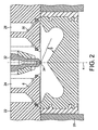
図2は、図1に概略的に示したピストンを、多気筒直噴ディーゼルエンジンの1つのシリンダ内の位置に示している。エンジンは、いずれもシリンダヘッド22によって閉じられるシリンダを定めているシリンダブロック20を備えている。シリンダヘッド22は、吸気バルブ26によって通常のやり方で制御される2つの吸気路24(その一方だけを見て取ることができる)を定めている。吸気ダクト24および吸気バルブ26は、シリンダおよびピストン頂部の凹所によって構成される燃焼室において、吸気ダクト24および吸気バルブ26を通って進入する吸気に実質的にピストンおよびシリンダの軸4を中心とする渦を生じさせるように、公知の様相で構成されている。さらにシリンダヘッドは、排気バルブ30によって従来からのやり方で制御される2つの排気路28(その一方だけを見て取ることができる)を定めている。さらにシリンダヘッド22には、シリンダの軸4に平行かつ同軸に配置された燃料インジェクタ34が収容されている。燃料インジェクタ32は、図2に示されるように、シリンダヘッドの下面の平面よりもきわめてわずかに下方に位置し、すなわちピストンが上死点の位置にあるときにピストンの凹所へとわずかに突き出す先端34を終端としている。燃料インジェクタの先端34には、複数の燃料噴射オリフィスが形成され、これらの燃料噴射オリフィスが、円すい形の突起5の表面に対して15〜19°の間の角度βだけ傾けられた角度で燃料の個々のジェットを放出するように配置されている。
FIG. 2 shows the piston schematically shown in FIG. 1 at a position in one cylinder of a multi-cylinder direct injection diesel engine. The engine includes a
使用時、燃料インジェクタは、ピストンが上死点位置または上死点位置のきわめて近くに位置するときに、燃料噴射オリフィスを通ってピストン頂部の凹所へと燃料を噴射するように動作する。吸気路24を通って進入する空気は、燃焼室において軸4を中心とする渦を急激に形成し、燃焼室へと噴射される燃料のジェット36は、突起5の表面から離れる角度で噴射される。したがって、これらのジェットは、突起5の表面に直接衝突する代わりに、凹所の下部環状体部分8を定めている凹所の側壁のアーチ形の部分に衝突する。側壁のこの部分の曲率および側壁のこの部分への燃料ジェットの入射の角度は、燃料ジェットが下方へとそらされ、すなわち凹所の底部に向かってそらされるような曲率および角度であり、したがって燃料は、図1および2の右側について見たときに時計方向に渦を巻くと同時に、当然ながらさらに軸4を中心としても渦を巻く。したがって、燃料は、図2の右側の矢印によって概略的に示されるように、凹所の側壁の下部に沿って下方へと、次いで凹所の底部に沿っておおむね水平に内側へと渦を巻き、その後に上方へと移動するように向きを変える。したがって、燃料の燃焼室における滞留時間が長くなり、この事実が燃焼室の寸法パラメータの最適化と組み合わさって、きわめて効率的な燃料および空気の混合をもたらし、結果として燃焼が実質的に完全になり、したがってきわめて効率的になり、燃え残りの炭化水素の量が最小になり、すす粒子の発生も最小になる。次いで、燃焼中の燃料および空気混合物が、燃焼室を離れ、シリンダの上部(今や、ピストンが図2に示されている上死点位置から離れて下方へと移動したためアクセス可能である)に進入する。しかしながら、環状のリップ12の燃焼室への突き出しが、側壁の部位14の凹状の形状と相俟って、燃焼室を出る燃焼中の燃料/空気混合物が、シリンダの側壁にほんのわずかに接触する実質的に垂直方向に延びる柱にて燃焼室を出ることを意味するため、燃焼中の燃料/空気混合物のシリンダ壁面における局所的な急冷が最小限になり、結果としてNOxの発生が最小限になる。さらに、燃焼中の燃料/空気混合物がシリンダの壁面にほとんど接触しないという事実は、発生するすす粒子(発生量自体が減っている)について、シリンダ壁面を覆う油の層に混入する割合が少ないことも意味する。
In use, the fuel injector operates to inject fuel through the fuel injection orifice into the recess at the top of the piston when the piston is located at or near the top dead center position. The air entering through the intake passage 24 rapidly forms a vortex centered on the shaft 4 in the combustion chamber, and the fuel jet 36 injected into the combustion chamber is injected at an angle away from the surface of the projection 5. The Thus, instead of impinging directly on the surface of the protrusion 5, these jets impinge on the arcuate portion of the recess sidewall defining the lower annular portion 8 of the recess. The curvature of this portion of the sidewall and the angle of incidence of the fuel jet on this portion of the sidewall is such that the fuel jet is deflected downward, i.e., deflected toward the bottom of the recess, and therefore the fuel Swirls clockwise when viewed on the right side of FIGS. 1 and 2, and naturally further swirls around the axis 4 as well. Thus, the fuel vortexes downward along the bottom of the recess sidewall and then generally horizontally inward along the bottom of the recess, as schematically illustrated by the arrow on the right side of FIG. Then, change the direction to move upward. Therefore, the residence time of the fuel in the combustion chamber is increased, and this fact, combined with optimization of the combustion chamber dimensional parameters, results in a very efficient fuel and air mixing, resulting in a substantially complete combustion. And therefore very efficient, minimizing the amount of unburned hydrocarbons and soot particles. The burning fuel and air mixture then leaves the combustion chamber and enters the top of the cylinder (now accessible because the piston has moved down from the top dead center position shown in FIG. 2). To do. However, the protrusion of the annular lip 12 into the combustion chamber, coupled with the concave shape of the
Claims (2)
前記シリンダは、前記シリンダヘッドの2つの吸気バルブおよび2つの排気バルブに連絡しており、
前記吸気バルブは、前記シリンダにおいて、流入する空気に該シリンダの軸をほぼ中心とする渦を生じさせるように構成された吸気バルブであり、
前記ピストンは、
該ピストンの頂部に形成された凹所を含む燃焼室を定めており、
前記凹所は、縦断面において該ピストンの軸を中心にして回転対称であり、底部と側壁とによって定められており、ほぼ円すい形または円すい台形の突起が前記底部から立ち上がっており、
前記凹所が、該ピストンの頂部から最も遠い下部環状体部分と、該ピストン頂部に最も近く、該ピストンの頂部に向かって直径が徐々に増加している上部とを含んでおり、
前記上部および下部が、縦断面においてアーチ形であって前記凹所へと突き出している環状のリップによって隔てられているピストンであり、
前記円すい形または円すい台形の突起の挟角が、104°〜108°の間であり、前記底部から該ピストンの頂部の平面までの前記凹所の最大深さが、該ピストンの直径の13〜22%の間であり、前記円すい形または円すい台形の突起が、該ピストンの直径の38〜44%の間の直径を有する円形の線に沿って前記底部と融合し、前記リップの直径が、該ピストンの直径の54〜59%の間であり、前記リップの最小径の前記線が、該ピストンの頂部の平面から該ピストンの直径の5〜10%の間の距離だけ離れた位置にあり、前記凹所の前記上部の直径が、前記リップの最小径の前記線における該ピストンの直径の54〜59%から、前記凹所の側壁が該ピストンの頂部の平面と交わる前記線における該ピストンの直径の72〜76%へと増加しており、
さらに前記シリンダヘッドが、複数の燃料噴射オリフィスを備える燃料インジェクタをほぼ前記シリンダの軸に位置させて保持しており、
前記オリフィスが、該オリフィスを通過する燃料ジェットが前記突起の表面から15〜19°で離れる角度に延びて、前記凹所の前記下部の前記アーチ形の側壁に最初に衝突するように配置されている、
ことを特徴とする直噴ディーゼルエンジン。 A direct injection diesel engine comprising a cylinder block closed by a cylinder head and defining at least one cylinder reciprocally receiving a piston;
The cylinder communicates with two intake valves and two exhaust valves of the cylinder head;
The intake valve is an intake valve configured to cause a vortex about the axis of the cylinder to occur in the flowing air in the cylinder;
The piston is
Defining a combustion chamber including a recess formed in the top of the piston;
The recess is rotationally symmetric about the axis of the piston in a longitudinal section and is defined by a bottom and a side wall, and a substantially conical or truncated trapezoidal protrusion rises from the bottom,
The recess includes a lower annulus portion furthest from the top of the piston and an upper portion closest to the piston top and gradually increasing in diameter toward the top of the piston;
The upper and lower portions are pistons that are arcuate in longitudinal section and separated by an annular lip projecting into the recess;
The included angle of the conical or truncated trapezoidal projection is between 104 ° and 108 °, and the maximum depth of the recess from the bottom to the plane of the top of the piston is 13 to 13 times the diameter of the piston. Between 22%, the conical or frustoconical protrusions merge with the bottom along a circular line having a diameter between 38 and 44% of the diameter of the piston, and the diameter of the lip is Between 54 and 59% of the diameter of the piston, and the line of minimum diameter of the lip is at a distance from the plane of the top of the piston by a distance between 5 and 10% of the diameter of the piston The diameter of the upper part of the recess is 54-59% of the diameter of the piston in the line with the smallest diameter of the lip, and the piston in the line where the side wall of the recess intersects the plane of the top of the piston To 72-76% of the diameter of Has increased,
Further, the cylinder head holds a fuel injector having a plurality of fuel injection orifices positioned substantially on the axis of the cylinder,
The orifice is positioned such that a fuel jet passing through the orifice extends at an angle of 15-19 ° away from the surface of the protrusion and first strikes the arched sidewall of the lower portion of the recess. Yes,
This is a direct-injection diesel engine.
Applications Claiming Priority (2)
| Application Number | Priority Date | Filing Date | Title |
|---|---|---|---|
| GBGB1001562.6A GB201001562D0 (en) | 2010-01-29 | 2010-01-29 | Direct injection diesel |
| PCT/GB2011/000095 WO2011092459A1 (en) | 2010-01-29 | 2011-01-26 | Direct injection diesel engines |
Publications (3)
| Publication Number | Publication Date |
|---|---|
| JP2013527360A JP2013527360A (en) | 2013-06-27 |
| JP2013527360A5 JP2013527360A5 (en) | 2014-04-10 |
| JP5826189B2 true JP5826189B2 (en) | 2015-12-02 |
Family
ID=42084241
Family Applications (1)
| Application Number | Title | Priority Date | Filing Date |
|---|---|---|---|
| JP2012550506A Active JP5826189B2 (en) | 2010-01-29 | 2011-03-31 | Direct injection diesel engine |
Country Status (7)
| Country | Link |
|---|---|
| US (1) | US8770168B2 (en) |
| EP (1) | EP2529094B1 (en) |
| JP (1) | JP5826189B2 (en) |
| KR (1) | KR20130044201A (en) |
| CN (1) | CN102892992B (en) |
| GB (1) | GB201001562D0 (en) |
| WO (1) | WO2011092459A1 (en) |
Families Citing this family (29)
| Publication number | Priority date | Publication date | Assignee | Title |
|---|---|---|---|---|
| US8978621B2 (en) | 2010-04-20 | 2015-03-17 | Caterpillar Inc. | Piston having combustion bowl shaped to balance combustion efficiency and emission properties |
| JP2013217306A (en) * | 2012-04-10 | 2013-10-24 | Isuzu Motors Ltd | Combustion chamber structure for direct injection engine |
| US10563569B2 (en) * | 2012-05-16 | 2020-02-18 | Dalian University Of Technology | Diesel combustion system |
| CN102661193B (en) * | 2012-05-16 | 2013-09-04 | 大连理工大学 | Double-layer split-flow burning system of direct-injection diesel engine |
| US20130319372A1 (en) * | 2012-06-04 | 2013-12-05 | Caterpillar, Inc. | Internal Combustion Engine Having Piston Configured For Reduced Particulate Emissions, And Method |
| KR101996085B1 (en) * | 2012-09-14 | 2019-07-03 | 두산인프라코어 주식회사 | COMBUSTION CHAMBER OF DIRECT INJECTION DIESEL ENGINE FOR REDUCING THE NOx |
| KR101366424B1 (en) * | 2012-09-14 | 2014-02-25 | 두산인프라코어 주식회사 | Combustion bowl shape of direct injection diesel engine for reducing the soot emission |
| EP2752564A1 (en) * | 2013-01-08 | 2014-07-09 | Perkins Engines Company Limited | Piston |
| US9617904B2 (en) | 2013-09-25 | 2017-04-11 | Anisun EcoTech Pvt Ltd. | Self cooled engine |
| FR3018550B1 (en) * | 2014-03-14 | 2019-04-12 | IFP Energies Nouvelles | METHOD FOR CONTROLLING FUEL INJECTION OF AN INTERNAL COMBUSTION ENGINE WITH DIRECT INJECTION, ESPECIALLY COMPRESSION IGNITION, AND ENGINE USING SUCH A METHOD |
| FR3020401B1 (en) * | 2014-04-24 | 2016-05-06 | Ifp Energies Now | DIRECT INJECTION INTERNAL COMBUSTION ENGINE HAVING A DOUBLE ANGLE OF FLOOR FOR CARRYING A CARBIDE MIXTURE IN A COMBUSTION COMBUSTION CHAMBER WITH A LOW COMBUSTION RATE AND A LOW COMPRESSION RATE AND METHOD FOR USING THE SAME. |
| EP3147476B1 (en) | 2014-05-22 | 2019-03-27 | Nissan Motor Co., Ltd | Combustion chamber structure for diesel engine |
| CN106460635B (en) * | 2014-05-22 | 2018-12-28 | 日产自动车株式会社 | The combustion chamber structure of diesel engine |
| JP6160564B2 (en) * | 2014-06-09 | 2017-07-12 | マツダ株式会社 | diesel engine |
| DE102014010714A1 (en) * | 2014-07-19 | 2016-01-21 | Deutz Aktiengesellschaft | combustion process |
| US9995213B2 (en) | 2015-03-31 | 2018-06-12 | Achates Power, Inc. | Asymmetrically-shaped combustion chamber for opposed-piston engines |
| US9840965B2 (en) | 2015-07-31 | 2017-12-12 | Achates Power, Inc. | Skewed combustion chamber for opposed-piston engines |
| US10184388B1 (en) | 2015-11-30 | 2019-01-22 | Caterpillar Inc. | Engine piston |
| GB2547265B (en) * | 2016-02-12 | 2020-03-04 | Perkins Engines Co Ltd | Piston bowl for an internal combustion engine |
| WO2018184171A1 (en) * | 2017-04-06 | 2018-10-11 | 上海长辛实业有限公司 | Piston for use in engine cylinder and piston engine |
| JP7005974B2 (en) * | 2017-07-11 | 2022-01-24 | いすゞ自動車株式会社 | Combustion chamber structure of direct injection internal combustion engine |
| KR102463469B1 (en) * | 2017-10-17 | 2022-11-04 | 현대자동차주식회사 | Diesel Engine having Reentrant Combustion Chamber |
| US10731600B2 (en) | 2017-11-07 | 2020-08-04 | Deere & Company | Piston with soot reducing piston bowl |
| JP7003626B2 (en) * | 2017-12-19 | 2022-01-20 | 三菱自動車工業株式会社 | Intake structure of internal combustion engine |
| CN108518287A (en) * | 2018-03-29 | 2018-09-11 | 天津中恒动力研究院有限公司 | Piston and engine assembly |
| CN108730064A (en) * | 2018-06-27 | 2018-11-02 | 天津内燃机研究所(天津摩托车技术中心) | Diesel engine piston combustion chamber |
| DK180103B1 (en) * | 2018-12-11 | 2020-05-04 | MAN Energy Solutions | Internal combustion engine |
| JP7124735B2 (en) * | 2019-01-29 | 2022-08-24 | マツダ株式会社 | Compression ignition engine controller |
| JP2021181765A (en) * | 2020-05-19 | 2021-11-25 | 株式会社小松製作所 | Piston for diesel engine and diesel engine |
Family Cites Families (34)
| Publication number | Priority date | Publication date | Assignee | Title |
|---|---|---|---|---|
| US4012A (en) * | 1845-04-26 | Improvement in electrographic printing | ||
| AT380311B (en) * | 1983-08-04 | 1986-05-12 | Avl Verbrennungskraft Messtech | PISTON FOR DIESEL ENGINES WITH DIRECT FUEL INJECTION |
| CN1074567A (en) | 1992-01-17 | 1993-07-21 | 陈为匡 | Can protect the driver of semiconductor switch |
| AT1974U1 (en) * | 1997-02-10 | 1998-02-25 | Avl List Gmbh | FOUR-STOCK COMBUSTION ENGINE |
| JP3751462B2 (en) * | 1998-03-27 | 2006-03-01 | 株式会社豊田中央研究所 | Direct injection diesel engine |
| DE60115841T2 (en) * | 2000-01-25 | 2006-08-17 | Kabushiki Kaisha Toyota Chuo Kenkyusho | DIRECTLY INJECTED INTERNAL COMBUSTION ENGINE |
| US6539910B1 (en) * | 2001-09-19 | 2003-04-01 | Federal-Mogul World Wide, Inc. | Closed gallery piston having con rod lubrication |
| DE10159644A1 (en) * | 2001-12-05 | 2003-07-03 | Bayerische Motoren Werke Ag | Combustion stratification combustion process for a direct-injection, spark-ignition internal combustion engine |
| FR2836696B1 (en) * | 2002-03-01 | 2004-05-28 | Inst Francais Du Petrole | METHOD AND ENGINE FOR PROVIDING THE MIXTURE OF AT LEAST ONE GAS FLUID, SUCH AS AIR, AND FUEL IN THE COMBUSTION CHAMBER OF A DIRECT INJECTION INTERNAL COMBUSTION ENGINE |
| US6732703B2 (en) | 2002-06-11 | 2004-05-11 | Cummins Inc. | Internal combustion engine producing low emissions |
| US7210448B2 (en) | 2002-06-11 | 2007-05-01 | Cummins, Inc. | Internal combustion engine producing low emissions |
| US8276563B2 (en) * | 2002-06-28 | 2012-10-02 | Cummins, Inc. | Internal combustion engine piston |
| AT7204U1 (en) | 2002-12-19 | 2004-11-25 | Avl List Gmbh | METHOD FOR OPERATING A DIRECTLY INJECTING DIESEL INTERNAL COMBUSTION ENGINE |
| US7438039B2 (en) * | 2004-02-06 | 2008-10-21 | Electro-Motive Diesel, Inc. | Large-bore, medium-speed diesel engine having piston crown bowl with acute re-entrant angle |
| DE102004045634A1 (en) * | 2004-09-21 | 2006-04-06 | Daimlerchrysler Ag | Internal combustion engine |
| JP3979416B2 (en) * | 2004-10-01 | 2007-09-19 | いすゞ自動車株式会社 | diesel engine |
| US6997158B1 (en) | 2004-10-07 | 2006-02-14 | International Engine Intellectual Property Company, Llc | Diesel combustion chamber |
| DE102004057558A1 (en) * | 2004-11-30 | 2006-06-01 | Mahle International Gmbh | Piston for internal combustion engine has base component consisting of forged aluminum and ring element of ni-resist, with closed annular cooling passage located between base component and ring element |
| JP4388075B2 (en) * | 2005-01-05 | 2009-12-24 | ヤマハ発動機株式会社 | Direct injection diesel engine |
| CN1944994A (en) * | 2005-10-08 | 2007-04-11 | 山东滨州渤海活塞股份有限公司 | Welded forged steel integrated piston and its producing method |
| DE102005061063A1 (en) * | 2005-12-21 | 2007-06-28 | Mahle International Gmbh | Piston for internal combustion engine has hub borings in form of borings of circular internal outline with resin coating containing solid lubricant particles |
| JP4906055B2 (en) * | 2006-02-08 | 2012-03-28 | 日野自動車株式会社 | Combustion chamber structure of direct injection diesel engine |
| US7458358B2 (en) * | 2006-05-10 | 2008-12-02 | Federal Mogul World Wide, Inc. | Thermal oxidation protective surface for steel pistons |
| BRPI0622232B1 (en) * | 2006-12-28 | 2019-11-12 | Volvo Lastvagnar Ab | internal combustion engine with a combustion chamber |
| CN201074556Y (en) * | 2007-08-16 | 2008-06-18 | 东风康明斯发动机有限公司 | Open type firebox piston for dual-valve diesel engine |
| US8539928B2 (en) * | 2007-12-10 | 2013-09-24 | Federal-Mogul World Wide, Inc. | Piston assembly and connecting rod having a profiled wrist pin bore therefor |
| FR2925604A1 (en) * | 2007-12-19 | 2009-06-26 | Renault Sas | COMBUSTION CHAMBER FOR THERMAL MOTOR WITH DIRECT OVERFLOW INJECTION |
| JP5227010B2 (en) * | 2007-12-21 | 2013-07-03 | 三菱自動車工業株式会社 | Piston for direct injection diesel engine |
| US8146563B2 (en) * | 2008-09-24 | 2012-04-03 | Deere & Company | Internal combustion engine with high squish piston |
| DE102009032941A1 (en) * | 2009-07-14 | 2011-01-20 | Mahle International Gmbh | Multi-part piston for an internal combustion engine and method for its production |
| US9970384B2 (en) * | 2009-11-06 | 2018-05-15 | Federal-Mogul Llc | Steel piston with cooling gallery and method of construction thereof |
| JP4924702B2 (en) * | 2009-12-01 | 2012-04-25 | トヨタ自動車株式会社 | Direct injection compression ignition engine |
| US8978621B2 (en) * | 2010-04-20 | 2015-03-17 | Caterpillar Inc. | Piston having combustion bowl shaped to balance combustion efficiency and emission properties |
| WO2012125961A1 (en) * | 2011-03-17 | 2012-09-20 | Cummins Intellectual Property, Inc. | Piston for internal combustion engine |
-
2010
- 2010-01-29 GB GBGB1001562.6A patent/GB201001562D0/en not_active Ceased
-
2011
- 2011-01-26 WO PCT/GB2011/000095 patent/WO2011092459A1/en active Application Filing
- 2011-01-26 KR KR1020127022283A patent/KR20130044201A/en not_active Application Discontinuation
- 2011-01-26 EP EP11702487.7A patent/EP2529094B1/en active Active
- 2011-01-26 US US13/575,792 patent/US8770168B2/en active Active
- 2011-01-26 CN CN201180007736.6A patent/CN102892992B/en active Active
- 2011-03-31 JP JP2012550506A patent/JP5826189B2/en active Active
Also Published As
| Publication number | Publication date |
|---|---|
| US8770168B2 (en) | 2014-07-08 |
| GB201001562D0 (en) | 2010-03-17 |
| CN102892992B (en) | 2015-11-25 |
| EP2529094A1 (en) | 2012-12-05 |
| KR20130044201A (en) | 2013-05-02 |
| WO2011092459A1 (en) | 2011-08-04 |
| EP2529094B1 (en) | 2019-01-02 |
| JP2013527360A (en) | 2013-06-27 |
| CN102892992A (en) | 2013-01-23 |
| US20130036998A1 (en) | 2013-02-14 |
Similar Documents
| Publication | Publication Date | Title |
|---|---|---|
| JP5826189B2 (en) | Direct injection diesel engine | |
| JP5054098B2 (en) | Method of operating an internal combustion engine and internal combustion engine for this method | |
| KR900007815B1 (en) | Structure of combustion chamber in diesel engine | |
| JP5762535B2 (en) | Self-igniting internal combustion engine | |
| EP3596320B1 (en) | A piston for an internal combustion engine | |
| CN210239842U (en) | Internal combustion engine | |
| CN102770633A (en) | A piston positioned for reciprocal movement in a combustion engine cylinder | |
| KR20070044068A (en) | Shape of combustion chamber of direct injection diesel engine | |
| RU2490486C2 (en) | Combustion chamber for thermal engine with direct injection and with supercharging | |
| CN107076007B (en) | Direct injection internal combustion engine with double cone angle for producing a fuel mixture in a dual zone combustion chamber having a low compression ratio and method of using the same | |
| CN100489283C (en) | Fuel injection system and method for injection | |
| JP2014148947A (en) | Diesel engine | |
| US11199155B2 (en) | Piston crown for a combustion system and an associated method thereof | |
| CN104903559A (en) | Piston | |
| RU2472949C2 (en) | Heat engine asymmetric combustion chamber | |
| CN110431292B (en) | Spark ignition type internal combustion engine | |
| CN110446834B (en) | Spark ignition type internal combustion engine | |
| CN110462178B (en) | Spark ignition type internal combustion engine | |
| US10774782B2 (en) | Piston design for flow re-direction | |
| US20200095920A1 (en) | Piston Design for Flow Re-Direction | |
| US10876495B2 (en) | Piston design for splitting jets into streams | |
| EP0828066B1 (en) | Combustion chamber of diesel engine | |
| US20070261664A1 (en) | Internal combustion engine with direct fuel injection | |
| CN110446835B (en) | Spark ignition type internal combustion engine | |
| KR20190033342A (en) | Swirl chamber type diesel engine |
Legal Events
| Date | Code | Title | Description |
|---|---|---|---|
| A521 | Request for written amendment filed |
Free format text: JAPANESE INTERMEDIATE CODE: A523 Effective date: 20130315 |
|
| A521 | Request for written amendment filed |
Free format text: JAPANESE INTERMEDIATE CODE: A523 Effective date: 20140218 |
|
| A621 | Written request for application examination |
Free format text: JAPANESE INTERMEDIATE CODE: A621 Effective date: 20140218 |
|
| A977 | Report on retrieval |
Free format text: JAPANESE INTERMEDIATE CODE: A971007 Effective date: 20141017 |
|
| A131 | Notification of reasons for refusal |
Free format text: JAPANESE INTERMEDIATE CODE: A131 Effective date: 20141021 |
|
| A601 | Written request for extension of time |
Free format text: JAPANESE INTERMEDIATE CODE: A601 Effective date: 20150121 |
|
| A601 | Written request for extension of time |
Free format text: JAPANESE INTERMEDIATE CODE: A601 Effective date: 20150219 |
|
| A521 | Request for written amendment filed |
Free format text: JAPANESE INTERMEDIATE CODE: A523 Effective date: 20150320 |
|
| TRDD | Decision of grant or rejection written | ||
| A01 | Written decision to grant a patent or to grant a registration (utility model) |
Free format text: JAPANESE INTERMEDIATE CODE: A01 Effective date: 20150929 |
|
| A61 | First payment of annual fees (during grant procedure) |
Free format text: JAPANESE INTERMEDIATE CODE: A61 Effective date: 20151013 |
|
| R150 | Certificate of patent or registration of utility model |
Ref document number: 5826189 Country of ref document: JP Free format text: JAPANESE INTERMEDIATE CODE: R150 |
|
| R250 | Receipt of annual fees |
Free format text: JAPANESE INTERMEDIATE CODE: R250 |
|
| R250 | Receipt of annual fees |
Free format text: JAPANESE INTERMEDIATE CODE: R250 |
|
| R250 | Receipt of annual fees |
Free format text: JAPANESE INTERMEDIATE CODE: R250 |
|
| R250 | Receipt of annual fees |
Free format text: JAPANESE INTERMEDIATE CODE: R250 |
|
| R250 | Receipt of annual fees |
Free format text: JAPANESE INTERMEDIATE CODE: R250 |
|
| R250 | Receipt of annual fees |
Free format text: JAPANESE INTERMEDIATE CODE: R250 |