JP5825519B2 - Steering device - Google Patents
Steering device Download PDFInfo
- Publication number
- JP5825519B2 JP5825519B2 JP2011283514A JP2011283514A JP5825519B2 JP 5825519 B2 JP5825519 B2 JP 5825519B2 JP 2011283514 A JP2011283514 A JP 2011283514A JP 2011283514 A JP2011283514 A JP 2011283514A JP 5825519 B2 JP5825519 B2 JP 5825519B2
- Authority
- JP
- Japan
- Prior art keywords
- steering
- nut
- stopper
- operation member
- screw shaft
- Prior art date
- Legal status (The legal status is an assumption and is not a legal conclusion. Google has not performed a legal analysis and makes no representation as to the accuracy of the status listed.)
- Expired - Fee Related
Links
- 238000001514 detection method Methods 0.000 claims description 55
- 230000002093 peripheral effect Effects 0.000 description 26
- 238000003780 insertion Methods 0.000 description 16
- 230000037431 insertion Effects 0.000 description 16
- 230000002159 abnormal effect Effects 0.000 description 11
- 230000005856 abnormality Effects 0.000 description 4
- 238000010586 diagram Methods 0.000 description 4
- 238000005452 bending Methods 0.000 description 1
- 230000013011 mating Effects 0.000 description 1
- 238000012986 modification Methods 0.000 description 1
- 230000004048 modification Effects 0.000 description 1
- 230000007935 neutral effect Effects 0.000 description 1
- 230000035939 shock Effects 0.000 description 1
Images


Classifications
-
- B—PERFORMING OPERATIONS; TRANSPORTING
- B62—LAND VEHICLES FOR TRAVELLING OTHERWISE THAN ON RAILS
- B62D—MOTOR VEHICLES; TRAILERS
- B62D5/00—Power-assisted or power-driven steering
- B62D5/001—Mechanical components or aspects of steer-by-wire systems, not otherwise provided for in this maingroup
-
- B—PERFORMING OPERATIONS; TRANSPORTING
- B62—LAND VEHICLES FOR TRAVELLING OTHERWISE THAN ON RAILS
- B62D—MOTOR VEHICLES; TRAILERS
- B62D5/00—Power-assisted or power-driven steering
- B62D5/008—Changing the transfer ratio between the steering wheel and the steering gear by variable supply of energy, e.g. by using a superposition gear
-
- B—PERFORMING OPERATIONS; TRANSPORTING
- B62—LAND VEHICLES FOR TRAVELLING OTHERWISE THAN ON RAILS
- B62D—MOTOR VEHICLES; TRAILERS
- B62D15/00—Steering not otherwise provided for
- B62D15/02—Steering position indicators ; Steering position determination; Steering aids
- B62D15/021—Determination of steering angle
- B62D15/0215—Determination of steering angle by measuring on the steering column
-
- B—PERFORMING OPERATIONS; TRANSPORTING
- B62—LAND VEHICLES FOR TRAVELLING OTHERWISE THAN ON RAILS
- B62D—MOTOR VEHICLES; TRAILERS
- B62D5/00—Power-assisted or power-driven steering
- B62D5/001—Mechanical components or aspects of steer-by-wire systems, not otherwise provided for in this maingroup
- B62D5/005—Mechanical components or aspects of steer-by-wire systems, not otherwise provided for in this maingroup means for generating torque on steering wheel or input member, e.g. feedback
Landscapes
- Engineering & Computer Science (AREA)
- Chemical & Material Sciences (AREA)
- Combustion & Propulsion (AREA)
- Transportation (AREA)
- Mechanical Engineering (AREA)
- Power Steering Mechanism (AREA)
- Steering Controls (AREA)
- Steering Control In Accordance With Driving Conditions (AREA)
Description
この発明は、ステアバイワイヤ式の操舵装置に関する。 The present invention relates to a steer-by-wire type steering apparatus.
ステアバイワイヤ式の操舵装置として特許文献1で開示された車両用操舵装置では、回転操作部材と車輪とが機械的に連結されておらず、回転操作部材の回転操作量に応じて制御される操舵用アクチュエータが車輪を転舵させる。
このようなステアバイワイヤ式の操舵装置では、回転操作部材の回転を検出する構成が重要であり、この構成に異常が生じてしまうと、操舵用アクチュエータが正常であっても、操舵不能になってしまう。回転操作部材の回転を検出する構成として、特許文献1では角度センサが1つしか設けられていないのだが、特許文献2の舵取装置では、当該構成の冗長化を図るために、メインの操舵角センサとバックアップ用の操舵角センサとが設けられている。そのため、特許文献2の舵取装置では、メインの操舵角センサの異常時においても、バックアップ用の操舵角センサによって操舵を継続できる。
In the vehicle steering apparatus disclosed in Patent Document 1 as a steer-by-wire steering apparatus, the rotation operation member and the wheel are not mechanically connected, and the steering is controlled according to the rotation operation amount of the rotation operation member. Actuators steer the wheels.
In such a steer-by-wire type steering device, a configuration for detecting the rotation of the rotary operation member is important. If an abnormality occurs in this configuration, steering becomes impossible even if the steering actuator is normal. End up. In Patent Literature 1, only one angle sensor is provided as a configuration for detecting the rotation of the rotation operation member. However, in the steering device of
特許文献2の舵取装置では、操舵角センサの異常時においても操舵を継続できるようにするために同じ操舵角センサを2つ設けているので、不必要な部品点数増加やコスト上昇が不可避となる。
この発明は、かかる背景のもとでなされたもので、操舵角センサの異常時においても操舵を継続できる構成を、部品点数増加やコスト上昇を回避しつつ実現できるステアバイワイヤ式の操舵装置を提供することを目的とする。
In the steering device of
The present invention has been made based on such a background, and provides a steer-by-wire type steering device capable of realizing a configuration capable of continuing steering even when the steering angle sensor is abnormal while avoiding an increase in the number of parts and an increase in cost. The purpose is to do.
請求項1記載の発明は、操舵するための操作部材(2)を含む操作機構(3)と、前記操作機構とは機械的に非連結であって、前記操作部材の操舵に基づいて車輪(4)を転舵させる転舵機構(5)とを有する操舵装置(1)であって、前記操作機構は、前記操作部材の操舵角度(θ)を検出する操舵角センサ(8)と、前記操作部材の操舵方向のみを検出する操舵方向検出手段(11)とを含み、前記操舵方向検出手段は、前記操作部材の操舵方向に回転可能なねじシャフト(40)と、前記ねじシャフトに螺合するナット(41)と、前記ねじシャフトと平行に配置され、前記ねじシャフトの回転に伴って前記ナットをねじシャフトの軸方向(J)に沿って移動させるナットガイド(42)と、前記ナットガイドの長手方向の少なくとも一端側に設けられ、前記ナットが前記軸方向に所定位置以上移動することを規制するストッパ(43)と、前記ストッパと前記ナットとの当接を検出する当接検出手段(70)とを含むことを特徴とする、操舵装置である。 According to the first aspect of the present invention, the operation mechanism (3) including the operation member (2) for steering and the operation mechanism are mechanically disconnected, and the wheel ( 4) a steering device (1) having a steering mechanism (5) for steering, wherein the operation mechanism includes a steering angle sensor (8) for detecting a steering angle (θ) of the operation member; look including a steering direction detecting means (11) for detecting only the steering direction of the operation member, the steering direction detection means includes a rotatable screw shaft (40) in the steering direction of the operation member, threaded on the threaded shaft A mating nut (41), a nut guide (42) arranged in parallel with the screw shaft and moving the nut along the axial direction (J) of the screw shaft as the screw shaft rotates, and the nut At least in the longitudinal direction of the guide Provided on an end side, wherein the nut comprises a stopper (43) which restricts movement of more than a predetermined position in the axial direction, the contact detection means and (70) for detecting the contact between the stopper and the nut This is a steering device.
請求項2記載の発明は、前記当接検出手段は、前記ストッパに設けられ、前記ナットの当接を検出する歪センサ(74)を含むことを特徴とする、請求項1記載の操舵装置である。
請求項3記載の発明は、前記ナットから突設され、前記ストッパに当接する当接凸部(71)を含むことを特徴とする、請求項2記載の操舵装置である。
According to a second aspect of the present invention, in the steering apparatus according to the first aspect, the contact detection means includes a strain sensor (74) provided on the stopper and detecting the contact of the nut. is there.
A third aspect of the present invention is the steering apparatus according to the second aspect, characterized in that the steering device includes a contact protrusion (71) protruding from the nut and contacting the stopper.
請求項4記載の発明は、前記歪センサは、前記ストッパにおいて前記ナットに対向する面(72C)とは反対側の面(72D)に設けられていることを特徴とする、請求項2または3記載の操舵装置である。
請求項5記載の発明は、前記ストッパに設けられ、前記歪センサが取り付けられており、弾性変形可能な取付部(72)を含むことを特徴とする、請求項2〜4のいずれかに記載の操舵装置である。
Fourth aspect of the present invention, said strain sensor is characterized in that provided on the opposite side (72D) is a surface opposed to the nut in the stopper (72C), according to
Invention of
なお、上記において、括弧内の数字等は、後述する実施形態における対応構成要素の参照符号を表すものであるが、これらの参照符号により特許請求の範囲を限定する趣旨ではない。 In addition, in the above, the numbers in parentheses represent reference numerals of corresponding components in the embodiments described later, but the scope of the claims is not limited by these reference numerals.
請求項1記載の発明によれば、操作機構と転舵機構とが機械的に非連結なステアバイワイヤ式の操舵装置では、操舵角センサによって操作部材の操舵角度を検出するだけでなく、操舵方向検出手段によって操作部材の操舵方向を検出することもできる。よって、操舵角センサに異常が発生しても、転舵機構は、操舵方向検出手段が検出した操舵方向に基づいて車輪を転舵させることができる。つまり、操舵装置は、操舵角センサの異常時においても操舵を維持できる。 According to the first aspect of the present invention, in the steer-by-wire type steering device in which the operation mechanism and the steering mechanism are mechanically disconnected, not only the steering angle of the operation member is detected by the steering angle sensor but also the steering direction. The steering direction of the operation member can also be detected by the detection means. Therefore, even if an abnormality occurs in the steering angle sensor, the steering mechanism can steer the wheels based on the steering direction detected by the steering direction detection means. That is, the steering device can maintain steering even when the steering angle sensor is abnormal.
ここで、操舵方向のみを検出する操舵方向検出手段は、操作部材の操舵角度(操舵方向および操舵量の両方)を検出する操舵角センサに比べて簡素な構成であるので、操舵方向検出手段を用いれば、操舵方向検出手段の代わりに操舵角センサを別途設ける場合に比べて、部品点数増加やコスト上昇を回避できる。
つまり、操舵角センサの異常時においても操舵を継続できる構成を、部品点数増加やコスト上昇を回避しつつ実現できる。
Here, the steering direction detecting means for detecting only the steering direction has a simpler configuration than the steering angle sensor for detecting the steering angle (both the steering direction and the steering amount) of the operation member. If used, it is possible to avoid an increase in the number of parts and an increase in cost compared to a case where a steering angle sensor is separately provided instead of the steering direction detecting means.
That is, it is possible to realize a configuration capable of continuing the steering even when the steering angle sensor is abnormal while avoiding an increase in the number of parts and an increase in cost.
操舵方向検出手段は、ねじシャフト、ナット、ナットガイド、ストッパおよび当接検出手段を含む安価かつ簡素な構成であり、操作部材の操舵(ねじシャフトの回転)に伴ってナットがねじシャフトの軸方向に沿って移動してストッパに当接したことに基づいて、操作部材の操舵方向を検出できる。このような操舵方向検出手段を用いれば、操舵角センサの異常時においても操舵を継続できる構成を、部品点数増加やコスト上昇を一層回避しつつ実現できる。 Misao steering direction detecting means, screw shafts, nut, nut guide, inexpensive and simple configuration including the stopper and the abutment detection means, the axis of the nut screw shaft with the steering operation member (the rotation of the screw shaft) The steering direction of the operating member can be detected based on the fact that it moves along the direction and comes into contact with the stopper. If such a steering direction detecting means is used, a configuration capable of continuing steering even when the steering angle sensor is abnormal can be realized while further avoiding an increase in the number of parts and an increase in cost.
請求項2記載の発明によれば、歪センサによって当接検出手段を簡素に構成できるので、操舵角センサの異常時においても操舵を継続できる構成を、部品点数増加やコスト上昇をより一層回避しつつ実現できる。
請求項3記載の発明によれば、ナットの当接凸部がストッパに当接することによってストッパが相対的に大きく撓むことから、歪センサ(当接検出手段)は、ストッパとナットとの当接を高精度に検出できる。
According to the second aspect of the present invention, since the contact detection means can be simply configured by the strain sensor, the configuration in which the steering can be continued even when the steering angle sensor is abnormal can further avoid the increase in the number of parts and the cost increase. Can be realized.
According to the invention described in
請求項4記載の発明によれば、ナットがストッパに当接する際、ナットが歪センサにぶつかることを防止できるので、歪センサの故障を防止できる。
請求項5記載の発明によれば、ナットがストッパに当接すると、ストッパでは取付部が相対的に大きく撓むことから、取付部に取り付けられた歪センサ(当接検出手段)は、取付部の撓みに基づいて、ストッパとナットとの当接を高精度に検出できる。
According to the fourth aspect of the present invention, when the nut abuts against the stopper, the nut can be prevented from colliding with the strain sensor, so that the failure of the strain sensor can be prevented.
According to the fifth aspect of the present invention, when the nut comes into contact with the stopper, the attachment portion of the stopper bends relatively greatly. Therefore, the strain sensor attached to the attachment portion (contact detection means) The contact between the stopper and the nut can be detected with high accuracy on the basis of the deflection.
本発明の好ましい実施の形態について、添付図面を参照しつつ説明する。
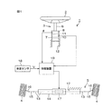
図1は、本発明の一実施形態における操舵装置1の概略構成を示す模式図である。図1を参照して、操舵装置1は、車両に適用される。操舵装置1は、ステアリングホイール等の回転可能な操作部材2を含む操作機構3と、操作部材2の操舵に基づいて車輪4を転舵させる転舵機構5とを有している。操舵装置1は、いわゆるステアバイワイヤ式の操舵装置であって、操作機構3と転舵機構5とが機械的に非連結となっている。
Preferred embodiments of the present invention will be described with reference to the accompanying drawings.
FIG. 1 is a schematic diagram showing a schematic configuration of a steering device 1 according to an embodiment of the present invention. With reference to FIG. 1, the steering device 1 is applied to a vehicle. The steering device 1 includes an
操作機構3は、操作部材2の他に、操作部材2の回転中心から延びる回転軸6と、回転軸6を回転可能に支持するハウジング7と、操舵角センサ8と、反力発生ユニット10と、操舵方向検出手段としての操舵方向検出ユニット11とを主に含んでいる。
回転軸6は、操作部材2に固定されている。これにより、操作部材2および回転軸6は、回転軸6の軸中心周りに一体回転可能である。そのため、操作部材2を回転操作したときの角度(「操舵角度」ということにする)は、回転軸6の回転角度と等しい。
In addition to the
The rotating
ハウジング7は、車体12に固定された中空円筒体であって、ハウジング7の中空部分に、回転軸6の一部(操作部材2側とは反対側の部分)が収容されている。
操舵角センサ8は、たとえばレゾルバやロータリーエンコーダー等であって、回転軸6の回転角度(つまり、操作部材2の操舵角度θ)を検出する。ここでの回転角度(操舵角度)は、回転軸6および操作部材2の回転量(操作部材2の操舵量)と、回転方向(操作部材2の操舵方向)とを含むベクトルである。操舵角センサ8は、ハウジング7に収容されている。
The
The
反力発生ユニット10は、回転軸6に摺擦することによって回転軸6の回転に抵抗を与える。この抵抗が、操舵反力として操作部材2に与えられる。操作部材2を操作するユーザは、操作部材2に与えられた操舵反力によって、車輪4が路面から受ける反力を擬似的に体感できる。反力発生ユニット10は、ハウジング7に収容されている。
操舵方向検出ユニット11は、操作部材2の操舵方向のみを検出するものであり、以降で詳説する。
The reaction
The steering
転舵機構5は、転舵軸13と、ハウジング14と、タイロッド15と、ナックルアーム16と、転舵アクチュエータ17とを主に含んでいる。
転舵軸13は、車体12の幅方向(車幅方向であり、図1では左右方向)に延びる軸状体である。
ハウジング14は、車幅方向に延びる中空体であり、その中空部分に転舵軸13が挿通されている。この状態で、転舵軸13の軸方向(車幅方向と同じ)における両端部は、ハウジング14からはみ出している。そして、転舵軸13は、車幅方向にスライド可能である。
The
The steered
The
タイロッド15は、転舵軸13の軸方向両端部に対して1本ずつ連結されている。
ナックルアーム16は、各タイロッド15において転舵軸13に連結された側とは反対側の端部に連結されている。ナックルアーム16に対して車輪4が連結されている。
転舵アクチュエータ17は、一例として、電動モータ(図示せず)と、この電動モータの駆動力(電動モータの出力軸の回転力)を転舵軸13の軸方向のスライドに変換するボールねじ装置(図示せず)とを含む。転舵アクチュエータ17の電動モータ(図示せず)が駆動力を発生すると、転舵軸13が車幅方向にスライドし、このスライドが転舵軸13の軸方向両端部のタイロッド15に伝達されることで、ナックルアーム16が回動し、車輪4の転舵が達成される。
One
The
As an example, the steering
なお、図1では、各車輪4が右側へ少し転舵した状態を示しているが、車両が直進しているときの車輪4の位置に対応する操作部材2の位置(回転方向における位置)が、操舵中立位置である。
また、操舵装置1は、車速Vを検出する車速センサ18と、操舵角センサ8や操舵方向検出ユニット11や車速センサ18の検出信号が入力される制御装置19とをさらに含んでいる。制御装置19は、ECU(Electronic Control Unit)とも呼ばれ、マイクロコンピュータで構成されている。
1 shows a state in which each wheel 4 is slightly steered to the right, but the position of the
The steering device 1 further includes a
車両の通常発進時や通常走行時において、制御装置19は、操舵角センサ8によって検出された操舵角度θや、車速センサ18によって検出された車速Vに基づいて目標転舵角を設定し、この目標転舵角まで車輪4が転舵するように、転舵アクチュエータ17を駆動制御する。
図2は、操舵装置1から操作機構3を抜き出して示した模式的な断面図である。図3は、操作機構3の要部の分解斜視図である。
When the vehicle starts normally or travels normally, the
FIG. 2 is a schematic cross-sectional view showing the
次に、図2および図3を参照して操作機構3、特に、操舵方向検出ユニット11について詳しく説明する。なお、図2では、操舵角センサ8の図示を省略している。また、図2に図示された操作部材2を時計回り(時計方向)に回転させると車輪4(図1参照)が右向きに転舵し、操作部材2を反時計回り(反時計方向)に回転させると車輪4が左向きに転舵するものとする。
Next, the
操作機構3において、前述したハウジング7は、図2では、横方向に延びており、ハウジング7において、横方向一端面(図2における右端面)には、丸い一端開口20が形成されていて、横方向他端面(図2における左端面)には、丸い他端開口21が形成されている。ハウジング7の中空部分は、一端開口20および他端開口21を介して外部に連通している。
In the
ハウジング7において、一端開口20を縁取る部分は、やや厚い環状板をなすフランジ22になっている。フランジ22の内周面において、ハウジング7の外部から最も遠い側(図2における左側)の端部には、径方向内側へ突出する位置決め凸部23が一体的に設けられている。また、フランジ22の内周面において、ハウジング7の外部から最も近い側(図2における右側)の端部には、周方向全域に亘って径方向外側へ窪む環状溝24が形成されている。環状溝24は、環状またはC字形状の位置決めリング25が径方向内側から嵌め込まれている。一端開口20には、環状の軸受26が同軸状で嵌め込まれている。軸受26は、位置決め凸部23と位置決めリング25とによって両側から挟持されることによって、ハウジング7に位置決めされている。
In the
ハウジング7の中空部分においてフランジ22側とは反対側の領域には、ホルダ27が収容されている。ホルダ27は、ハウジング7と同軸状をなす中空円筒状であり、軸方向一端が塞がれていて、軸方向他端が開放されている。ホルダ27は、ハウジング7においてフランジ22以外の部分の内径とほぼ同じ外径を有する円周壁28と、円周壁28の軸方向一端に連結される円板状の端壁29とを一体的に備えている。
A
ホルダ27は、ハウジング7に対して他端開口21から嵌め込まれている。ホルダ27では、端壁29が、他の部分よりもハウジング7の一端開口20側(図2における右側)に位置している。円周壁28の外周面がハウジング7の内周面に接続されることによって、ホルダ27は、ハウジング7に対して一体化されており、ハウジング7の一部になっている。円周壁28において、端壁29が連結された側とは反対側の軸方向他端縁によって区画された部分は、開口30となっている。開口30は、ハウジング7の他端開口21と軸方向J(ハウジング7およびホルダ27の軸方向)において同じ位置にある。開口30および他端開口21を介してホルダ27の中空部分がハウジング7の外部に連通している。円周壁28の内周面において開口30の周囲の領域には、ねじ部31が形成されている。
The
端壁29の円中心位置には、端壁29を厚さ方向(軸方向J)に貫通する丸い軸挿通孔32が形成されている。端壁29では、軸挿通孔32を縁取る部分が、端壁29の内周面となっている。端壁29の内周面において開口30側の端部(図2における左端部)には、径方向内側へ突出する位置決め凸部33が一体的に設けられている。軸挿通孔32には、環状の軸受34が同軸状で嵌め込まれている。軸受34は、位置決め凸部33によって開口30側(図2における左側)から当接されることによって、ハウジング7に位置決めされている。
A round
操舵方向検出ユニット11は、ねじシャフト40と、ナット41と、ナットガイド42と、ストッパ43と、当接検出手段としての当接検出センサ70とを含んでいる。
ねじシャフト40は、軸状体であって、回転軸6に対して同軸状で連結されている。ねじシャフト40と回転軸6とは一体形成されていてもよいし、分離可能であってもよい。ねじシャフト40は、回転軸6に近い側から順に、第1ねじ形成部45、第1支持部46、第2ねじ形成部47および第2支持部48を一体的に有している。
The steering
The
第1ねじ形成部45の外周面には、ねじ部49が形成されている。
第1支持部46の外周面は、凹凸のない円周面である。第1支持部46は、第1ねじ形成部45とほぼ同径である。
第2ねじ形成部47は、第1支持部46よりも少し大径である。そのため、第2ねじ形成部47において第1支持部46に隣接する端部には、段付き51が形成されている。第2ねじ形成部47の外周面には、ねじ部52が形成されている。なお、ねじ部52は、第2ねじ形成部47の外周面の全域に形成されていなくてもよい。図2では、第2ねじ形成部47の外周面において段付き51周辺の領域には、ねじ部52が形成されていない。
A
The outer peripheral surface of the
The second
第2支持部48の外周面は、凹凸のない円周面である。第2支持部48は、第2ねじ形成部47よりも少し小径である。そのため、第2ねじ形成部47において第2支持部48に隣接する端部には、段付き53が形成されている。
ねじシャフト40は、ハウジング7の一端開口20および他端開口21に挿通された状態でハウジング7に部分的に収容されている。また、ねじシャフト40は、ハウジング7内のホルダ27の開口30および軸挿通孔32に挿通された状態でホルダ27に部分的に収容されている。このとき、ねじシャフト40は、ハウジング7およびホルダ27のそれぞれに対して同軸状になっている。そのため、ねじシャフト40(回転軸6)の軸方向は、前述した軸方向Jと同じである。
The outer peripheral surface of the
The
ねじシャフト40では、第1ねじ形成部45における大部分(第1支持部46側の端部を除く部分)が、一端開口20からハウジング7の外にはみ出しており、回転軸6につながっている。第1支持部46は、前述した軸受26に対して内嵌されている。
ここで、第1ねじ形成部45のねじ部49に対して、環状の位置決めナット54が径方向外側から螺合しており、位置決めナット54は、軸受26に対してハウジング7の外側から当接している。位置決めナット54は、ねじシャフト40の一部とみなすことができる。軸受26は、位置決めナット54および段付き51によって軸方向Jにおける両側から挟持されることで、ねじシャフト40に対して位置決めされている。
In the
Here, an
また、ねじシャフト40では、第2ねじ形成部47が、ハウジング7の中空部分においてフランジ22とホルダ27の端壁29とに挟まれた領域(「検出領域」ということにする)Xに配置されている。
第2支持部48は、ホルダ27の中空部分に配置されている。第2支持部48において第2ねじ形成部47側の端部は、前述した軸受34に対して内嵌されている。ここで、軸受34は、第2ねじ形成部47において第2支持部48側の段付き53とホルダ27の端壁29における位置決め凸部33とによって軸方向Jにおける両側から挟持されることで、ねじシャフト40に対して位置決めされている。
In the
The
ねじシャフト40は、軸受26および軸受34が位置決めされた軸方向Jにおける2箇所において、ハウジング7(ホルダ27も含む)によって回転可能に支持されている。ねじシャフト40は、回転軸6を介して操作部材2につながっているので、ねじシャフト40の回転方向(図2における1点鎖線の矢印を参照)は、操作部材2の操舵方向と同じである。つまり、ねじシャフト40は、操作部材2の操舵方向に回転可能である。また、操作部材2の操舵角度θ(図1参照)は、ねじシャフト40の回転角度と等しい。
The
ここで、ナット41、ナットガイド42、ストッパ43および力検出センサ44よりも先に、前述した反力発生ユニット10について説明する。反力発生ユニット10は、ホルダ27に収容されている。反力発生ユニット10は、ねじシャフト40の第2支持部48を非接触で取り囲む環状のプラグ61と、プラグ61よりも端壁29側において第2支持部48に対して外嵌される環状の摺擦リング62と、摺擦リング62に対して外嵌される環状の押圧リング63と、プラグ61および押圧リング63間に圧縮状態で介装されるばね64とを含む。
Here, the reaction
プラグ61の外周面には、ねじ部65が形成されており、ねじ部65は、ホルダ27のねじ部31に対して径方向内側から螺合している。摺擦リング62の外周面62Aおよび押圧リング63の内周面63Aは、いずれも、プラグ61から離れる方向(図2における右側)に向かうに従って拡径する円錐面であり、互いに面接触している。押圧リング63は、ばね64によってプラグ61から離れる方向へ付勢されつつ、内周面63Aによって摺擦リング62を径方向内側へ押圧している。これにより、太線矢印で示すように、摺擦リング62が縮径され、摺擦リング62の内周面62Bがねじシャフト40の第2支持部48に対して圧接している。操作部材2の操舵に伴ってねじシャフト40を回転させると、第2支持部48と摺擦リング62の内周面62Bとの間の摩擦が、前述した操舵反力として操作部材2に与えられる。プラグ61を押圧リング63側へねじ込むと、ばね64の付勢力が強くなるので、その分、第2支持部48と摺擦リング62の内周面62Bとの間の摩擦が大きくなり、操舵反力も大きくなる。このように、プラグ61のねじ込み量によって、操舵反力を調整できる。
A
ナット41は、環状体である。図2では、説明の便宜上、ナット41の断面に相当する部分に、右上に延びるハッチングを付している。ナット41の内周面には、ねじ部55が形成されている。ナット41には、ナット41を軸方向(肉厚方向)に貫通する丸い挿通孔56が形成されている。挿通孔56は、単数または複数(この実施形態では2つ)形成されており、複数形成される場合には、周方向に等間隔で形成されている(図3参照)。ナット41は、前述した検出領域Xに配置されていて、ねじシャフト40の第2ねじ形成部47に対して外嵌されている。このとき、ナット41のねじ部55が第2ねじ形成部47のねじ部52に対して螺合している。つまり、ナット41は、ねじシャフト40に螺合しているとともに、ねじシャフト40と同軸状になっている。そのため、ナット41の軸方向は、前述した軸方向Jと同じである。
The
ナット41の軸方向両端面の外側周縁部において周方向で同じ位置には、円柱状の当接凸部71が、軸方向に沿ってナット41の外方へ突設されている。この実施形態では、軸方向両側で1対をなす当接凸部71が、ナット41の周方向における1箇所に設けられているが(図3参照)、1対の当接凸部71は、周方向における複数箇所に設けられていてもよい。複数箇所に当接凸部71が設けられる場合、当接凸部71は、周方向に等間隔で設けられることが好ましい。
ナットガイド42は、軸状体であり、ナット41の挿通孔56と同じ数(ここでは2つ)だけ設けられている。ナットガイド42は、検出領域Xにおいて、ねじシャフト40の第2ねじ形成部47と平行に配置されていて、ナット41の挿通孔56に対して1つずつ挿通されている。つまり、各ナットガイド42(詳しくは両端の間の部分)は、対応する挿通孔56においてナット41を貫通している。
The nut guides 42 are shaft-like bodies and are provided in the same number (two here) as the insertion holes 56 of the
ストッパ43は、軸方向Jに薄くハウジング7の径方向に沿って延びる板状体であって、検出領域Xにおけるハウジング7の内周面に固定されており、当該内周面からねじシャフト40の第2ねじ形成部47側へ延びている。ストッパ43は、ナット41の軸方向両側に設けられている。
なお、図2では、説明の便宜上、ストッパ43の断面に相当する部分に、右下に延びるハッチングを付している。また、図3では、説明の便宜上、ナットガイド42を実際よりも長くなるように誇張して示している。
The
In FIG. 2, for convenience of explanation, the portion corresponding to the cross section of the
また、図2において、軸方向Jにおける同じ位置に表れている2つのストッパ43(ナット41に対して軸方向Jの両側における上下2つのストッパ43)は、第2ねじ形成部47を非接触で取り囲む環状体の一部として一体化されている(図3参照)。そのため、ナット41の2つの挿通孔56に対して軸方向両側のそれぞれに、細長板状かつ環状をなすストッパ43(図3参照)が1つずつ(合計2つ)設けられている。各ストッパ43では、軸方向Jから見て当接凸部71側とは反対側(図2における下側)の部分だけがハウジング7の内周面に固定されており、ストッパ43は、当該部分以外の領域ではハウジング7の内周面に対して非接触となっている。
In FIG. 2, two stoppers 43 (upper and lower two
各ストッパ43において、軸方向Jから見て当接凸部71と重なる位置(図2における上端部)には、取付部72が一体的に設けられている。図3を参照して、各ストッパ43には、軸方向Jから見て当接凸部71と重なる部分を挟むように平行に延びる1対の切欠溝73が形成されている。そして、各ストッパ43では、1対の切欠溝73に挟まれた当該部分が取付部72である。取付部72は、切欠溝73に沿って延びる小片状をなしている。取付部72は、ストッパ43に連結された基端72Aと、基端72Aとは反対側(図2における上側)にあってストッパ43とは非接触の先端72Bとを有している。取付部72は、基端72Aを中心に先端72Bが揺動するように弾性変形可能である。詳しくは、各ストッパ43の取付部72は、ナット41に対して軸方向Jに接離するように弾性変形可能である。そして、取付部72において、ナット41に対向する面72Cとは反対側の面72Dには、基端72A側に凹部75が形成されている(図2も参照)。そのため、取付部72の軸方向Jにおける厚さは、凹部75が形成された基端72A側において、先端72B側よりも薄くなっているので、取付部72は、凹部75が形成されない場合よりも、弾性変形し易くなっている。
In each
なお、取付部72は、ストッパ43の一部であるので、取付部72においてナット41に対向する面72Cとは反対側の面72Dは、ストッパ43においてナット41に対向する面とは反対側の面でもある。
そして、図2を参照して、ナット41の各挿通孔56に挿通されたナットガイド42は、軸方向Jにおける挿通孔56の両側に位置する各ストッパ43に固定されている。そのため、ストッパ43は、ナットガイド42の長手方向(軸方向Jでもある)の両端に1つずつ設けられていて、ナットガイド42の長手方向における一端側および他端側を保持している。これにより、ナットガイド42がナット41の挿通孔56に挿通された状態が維持されている。
Since the mounting
With reference to FIG. 2, the
ここで、各ナットガイド42は、挿通孔56に対して、若干の遊びを持って挿通されていてもよい。
当接検出センサ70は、歪センサ(歪ゲージ)74を含んでいる。歪センサ74は、各ストッパ43に1つずつ設けられており、詳しくは、ストッパ43における取付部72の凹部75の底(取付部72において薄くて歪みやすい部分)に1つずつ取り付けられている。
Here, each
The
図4は、当接検出センサ70の構成を示す電気回路図である。
図4を参照して、当接検出センサ70は、抵抗R1、R2、R3およびR4を含むブリッジ回路76を含む。このブリッジ回路76では、抵抗R1および抵抗R3が直列接続されていて、抵抗R2および抵抗R4が直列接続されていて、抵抗R1および抵抗R3の直列接続部分と抵抗R2および抵抗R4の直列接続部分とが並列接続されている。このようなブリッジ回路76を含む当接検出センサ70は、制御装置19に対して電気的に接続されている。
FIG. 4 is an electric circuit diagram showing a configuration of the
4,
このブリッジ回路76での出力電力Eは、以下の式で表される。なお、以下の式におけるR1、R2、R3およびR4は、それぞれの抵抗における抵抗値である。
E=(R1・R3−R2・R4)/(R1+R2)・(R3+R4)
この実施形態では、1対のストッパ43のうち、一方(図2における右側)のストッパ43の歪センサ74が、抵抗R1であり、他方(図2における左側)のストッパ43の歪センサ74が、抵抗R2である。いずれかの歪センサ74が圧縮または引張された場合にのみ、出力電力Eが発生する。
The output power E in the
E = (R1 · R3-R2 · R4) / (R1 + R2) · (R3 + R4)
In this embodiment, the
図2を参照して、ユーザが操作部材2を操舵することによって時計方向または反時計方向に回転させると、回転軸6およびねじシャフト40も操作部材2と共回りする。このとき、ねじシャフト40に螺合したナット41もねじシャフト40と共回りしようとする。しかし、ナット41の各挿通孔56に対してナットガイド42が挿通されていることによって、ナット41は回転できず、代わりに、ナットガイド42(換言すれば、ねじシャフト40の軸方向J)に沿ってスライドする(1点鎖線の矢印参照)。つまり、ナットガイド42は、ねじシャフト40の回転に伴ってナット41をねじシャフト40の軸方向Jに沿って移動させる。
Referring to FIG. 2, when the user turns the
たとえば、ユーザが操作部材2(換言すれば、ねじシャフト40)を図2における時計方向に回転させると、ナット41は、ナットガイド42に沿って操作部材2に近付く方向(図2における右側)へスライドする。そして、操作部材2を引き続き同じ方向へ回転させ、最終的に、操作部材2に最も近い側(図2における右側)のストッパ43にナット41が当接すると、ナット41は、これ以上スライドできなくなり、操作部材2は、これ以上同じ方向(時計方向)に回転させることができなくなる。つまり、ストッパ43は、ナット41がストッパ43に当接する所定位置以上、軸方向J(図2における右側)に移動することを規制する。ナット41がストッパ43に当接する際、ナット41では、当該ストッパ43側(図2における右側)の当接凸部71がストッパ43の取付部72に当接する。これにより、この取付部72が、ナット41から離間する方向へ弾性変形する。これに応じて、この取付部72に取り付けられた歪センサ74(抵抗R1)における歪量が所定の閾値を超えるとともに、抵抗R1の抵抗値が増加し、前述した出力電力Eが正の値まで増加する。
For example, when the user rotates the operation member 2 (in other words, the screw shaft 40) in the clockwise direction in FIG. 2, the
逆に、ユーザが操作部材2を図2における反時計方向に回転させると、ナット41は、ナットガイド42に沿って操作部材2から離れる方向(図2における左側)へスライドする。そして、操作部材2を引き続き同じ方向へ回転させ、最終的に、操作部材2から最も遠い側(図2における左側)のストッパ43にナット41が当接すると、ナット41は、これ以上スライドできなくなり、操作部材2は、これ以上同じ方向(反時計方向)に回転させることができなくなる。つまり、ストッパ43は、ナット41がストッパ43に当接する所定位置以上、軸方向J(図2における左側)に移動することを規制する。ナット41がストッパ43に当接する際、ナット41では、当該ストッパ43側(図2における左側)の当接凸部71がストッパ43の取付部72に当接する。これにより、この取付部72が、ナット41から離間する方向へ弾性変形する。これに応じて、この取付部72に取り付けられた歪センサ74(抵抗R2)における歪量が所定の閾値を超えるとともに、抵抗R2の抵抗値が増加し、前述した出力電力Eが負の値まで減少する。
Conversely, when the user rotates the
このように、歪センサ74を含む当接検出センサ70は、歪センサ74(抵抗R1、R2)における歪量が所定の閾値を超えることによって、ストッパ43とナット41との当接(換言すれば、操作部材2の端当て)を検出している。ここで、ナット41の当接凸部71がストッパ43に当接すると、ストッパ43では取付部72が相対的に大きく撓むことから、取付部72に取り付けられた歪センサ74(当接検出センサ70)は、取付部72の撓みに基づいて、ストッパ43とナット41との当接を高精度に検出できる。また、ナット41がストッパ43に当接したときに取付部72が撓む(弾性変形する)ことによって、当接時(端当て時)のショックを緩和できるので、ユーザにとって操作部材2の操作性の向上を図ることができる。そして、歪センサ74が、ナット41に対向しない面72Dに設けられていることから、ナット41がストッパ43に当接する際、ナット41が歪センサ74にぶつかることを防止できるので、歪センサ74の故障を防止できる。
As described above, the
いずれかの歪センサ74(抵抗R1、R2)における歪量と、当接検出センサ70が検出した出力電力Eは、制御装置19(図1参照)に入力される。歪センサ74(抵抗R1、R2)における歪量が所定の閾値を超えた場合において、制御装置19は、入力された出力電力Eに応じて、出力電力Eが正であれば、操作部材2の操舵方向が図2における時計方向であると判断し、出力電力Eが負であれば、操作部材2の操舵方向が図2における反時計方向であると判断する。このように、制御装置19には、操舵角センサ8が検出した操舵角度θ(図1参照)だけでなく、当接検出センサ70が検出した出力電力E(操作部材2の操舵方向)も入力されるようになっている。
The strain amount in any one of the strain sensors 74 (resistors R1 and R2) and the output power E detected by the
図1を参照して、たとえば、操舵角センサ8に異常が発生した場合には、制御装置19には、操舵角センサ8から検出結果(操舵角度θ)が入力されなくなる。この場合、制御装置19は、操舵方向検出ユニット11の当接検出センサ70から入力された出力電力Eによって、ユーザによる操作部材2の操舵方向を取得する。そして、出力電力Eが正である場合(操作部材2の操舵方向が時計方向である場合)には、出力電力Eが正である期間または出力電力Eが正になってから所定の期間内において、車輪4が所定の速さで右向きに所定角度だけ転舵するように転舵アクチュエータ17を駆動制御する。一方、出力電力Eが負である場合(操作部材2の操舵方向が反時計方向である場合)には、出力電力Eが負である期間または出力電力Eが負になってから所定の期間内において、車輪4が所定の速さで左向きに所定角度だけ転舵するように転舵アクチュエータ17を駆動制御する。
With reference to FIG. 1, for example, when an abnormality occurs in the
以上のように、ステアバイワイヤ式の操舵装置1では、操舵角センサ8によって操作部材2の操舵角度θを検出するだけでなく、操舵方向検出ユニット11によって操作部材2の操舵方向を検出することもできる。よって、操舵角センサ8に異常が発生しても、転舵機構5は、フェイルセーフ機構としての操舵方向検出ユニット11が検出した操舵方向に基づいて車輪4を転舵させることができる。つまり、操舵装置1は、操舵角センサ8が正常な場合より精度が落ちるものの、操舵角センサ8の異常時においても操舵を最低限維持できる。
As described above, in the steer-by-wire type steering apparatus 1, not only the
ここで、操舵方向のみを検出する操舵方向検出ユニット11は、操作部材2の操舵角度θ(操舵方向および操舵量の両方)を検出する操舵角センサ8に比べて簡素な構成であるので、操舵方向検出ユニット11を用いれば、操舵方向検出ユニット11の代わりに操舵角センサ8を別途設ける場合に比べて、部品点数増加やコスト上昇を回避できる。
つまり、操舵角センサ8の異常時においても操舵を継続できる構成を、部品点数増加やコスト上昇を回避しつつ実現し、操舵装置1の冗長性を確保できる。
Here, the steering
That is, a configuration capable of continuing the steering even when the
また、図2に示すように、操舵方向検出ユニット11は、ねじシャフト40、ナット41、ナットガイド42、ストッパ43および当接検出センサ70を含む安価かつ簡素な構成である。操舵方向検出ユニット11は、操作部材2の操舵(ねじシャフト40の回転)に伴ってナット41がねじシャフト40の軸方向Jに沿って移動してストッパ43に当接したことに基づいて、操作部材2の操舵方向を検出できる。このような操舵方向検出ユニット11を用いれば、操舵角センサ8の異常時においても操舵を継続できる構成を、部品点数増加やコスト上昇を一層回避しつつ実現できる。特に、既存の操作機構3に、操舵方向検出ユニット11を追加する場合にも、操作機構3における大幅な設計変更が省略できるので、部品点数増加やコスト上昇の回避を確実に達成できる。
As shown in FIG. 2, the steering
そして、歪センサ74によって当接検出センサ70を簡素に構成できるので、操舵角センサ8の異常時においても操舵を継続できる構成を、部品点数増加やコスト上昇をより一層回避しつつ実現できる。
この発明は、以上に説明した実施形態に限定されるものではなく、請求項記載の範囲内において種々の変更が可能である。
Since the
The present invention is not limited to the embodiment described above, and various modifications can be made within the scope of the claims.
たとえば、前述の実施形態では、ストッパ43が、ナットガイド42の長手方向における両端側に設けられていたので、操舵方向検出ユニット11は、操作部材2の時計方向および反時計方向の両方向の操舵方向を検出できる(図2参照)。しかし、当該両方向のうちいずれか一方の操舵方向が検出できればよいのであれば、ストッパ43は、ナットガイド42の長手方向における一端側または他端側だけに設けられていればよい。
For example, in the above-described embodiment, the
また、当接検出センサ70として、歪センサ74の代わりに、圧電素子などで構成された感圧センサや近接センサを用いることもできる。また、当接検出センサ70として、各ストッパ43に設けられてナット41に当接されることによってONされるスイッチを用いることができる。スイッチを用いる場合、制御装置19(図1参照)は、図2における左右のストッパ43のスイッチのうち、どちらがONになるかで操作部材2の操舵方向を判断する。
Further, as the
また、当接検出センサ70を、各ストッパ43でなく、ナット41の軸方向両端面においてストッパ43に当接する部分に設けてもよい。
Further, the
1…操舵装置、2…操作部材、3…操作機構、4…車輪、5…転舵機構、8…操舵角センサ、11…操舵方向検出ユニット、40…ねじシャフト、41…ナット、42…ナットガイド、43…ストッパ、70…当接検出センサ、71…当接凸部、72…取付部、72C…面、72D…面、74…歪センサ、J…軸方向、θ…操舵角度 DESCRIPTION OF SYMBOLS 1 ... Steering device, 2 ... Operation member, 3 ... Operation mechanism, 4 ... Wheel, 5 ... Steering mechanism, 8 ... Steering angle sensor, 11 ... Steering direction detection unit, 40 ... Screw shaft, 41 ... Nut, 42 ... Nut Guide, 43 ... Stopper, 70 ... Contact detection sensor, 71 ... Contact projection, 72 ... Mounting portion, 72C ... Surface, 72D ... Surface, 74 ... Strain sensor, J ... Axial direction, [theta] ... Steering angle
Claims (5)
前記操作機構は、
前記操作部材の操舵角度を検出する操舵角センサと、
前記操作部材の操舵方向のみを検出する操舵方向検出手段とを含み、
前記操舵方向検出手段は、
前記操作部材の操舵方向に回転可能なねじシャフトと、
前記ねじシャフトに螺合するナットと、
前記ねじシャフトと平行に配置され、前記ねじシャフトの回転に伴って前記ナットをねじシャフトの軸方向に沿って移動させるナットガイドと、
前記ナットガイドの長手方向の少なくとも一端側に設けられ、前記ナットが前記軸方向に所定位置以上移動することを規制するストッパと、
前記ストッパと前記ナットとの当接を検出する当接検出手段とを含むことを特徴とする、操舵装置。 An operation mechanism including an operation member for steering, and a steering device having a steering mechanism that is mechanically disconnected from the operation mechanism and steers a wheel based on steering of the operation member. ,
The operating mechanism is
A steering angle sensor for detecting a steering angle of the operation member;
Look including the steering direction detection means for detecting only the steering direction of the operation member,
The steering direction detecting means includes
A screw shaft rotatable in the steering direction of the operating member;
A nut screwed onto the screw shaft;
A nut guide that is arranged in parallel with the screw shaft and moves the nut along the axial direction of the screw shaft as the screw shaft rotates;
A stopper that is provided on at least one end side in the longitudinal direction of the nut guide and restricts the nut from moving a predetermined position or more in the axial direction;
A steering apparatus comprising: contact detection means for detecting contact between the stopper and the nut .
Priority Applications (4)
| Application Number | Priority Date | Filing Date | Title |
|---|---|---|---|
| JP2011283514A JP5825519B2 (en) | 2011-12-26 | 2011-12-26 | Steering device |
| US13/721,743 US8662240B2 (en) | 2011-12-26 | 2012-12-20 | Steering system |
| EP12198843.0A EP2610131B1 (en) | 2011-12-26 | 2012-12-21 | Steering system |
| CN201210564389.3A CN103171618B (en) | 2011-12-26 | 2012-12-21 | Handle transfer |
Applications Claiming Priority (1)
| Application Number | Priority Date | Filing Date | Title |
|---|---|---|---|
| JP2011283514A JP5825519B2 (en) | 2011-12-26 | 2011-12-26 | Steering device |
Publications (3)
| Publication Number | Publication Date |
|---|---|
| JP2013132949A JP2013132949A (en) | 2013-07-08 |
| JP2013132949A5 JP2013132949A5 (en) | 2015-01-22 |
| JP5825519B2 true JP5825519B2 (en) | 2015-12-02 |
Family
ID=47631211
Family Applications (1)
| Application Number | Title | Priority Date | Filing Date |
|---|---|---|---|
| JP2011283514A Expired - Fee Related JP5825519B2 (en) | 2011-12-26 | 2011-12-26 | Steering device |
Country Status (4)
| Country | Link |
|---|---|
| US (1) | US8662240B2 (en) |
| EP (1) | EP2610131B1 (en) |
| JP (1) | JP5825519B2 (en) |
| CN (1) | CN103171618B (en) |
Cited By (1)
| Publication number | Priority date | Publication date | Assignee | Title |
|---|---|---|---|---|
| KR101944338B1 (en) * | 2017-07-27 | 2019-01-31 | 주식회사 만도 | Limiting apparatus of steering wheel rotation |
Families Citing this family (12)
| Publication number | Priority date | Publication date | Assignee | Title |
|---|---|---|---|---|
| JP6115757B2 (en) * | 2012-02-17 | 2017-04-19 | 株式会社ジェイテクト | Vehicle steering system |
| JP5871164B2 (en) * | 2012-03-02 | 2016-03-01 | 株式会社ジェイテクト | Vehicle steering system |
| JP6020885B2 (en) * | 2012-06-07 | 2016-11-02 | 株式会社ジェイテクト | Vehicle steering system |
| JP2017004099A (en) | 2015-06-05 | 2017-01-05 | 株式会社東海理化電機製作所 | Rotation operation device |
| KR102637038B1 (en) * | 2017-02-17 | 2024-02-15 | 에이치엘만도 주식회사 | Stopper structure and steer-by-wire system having the same |
| US10895278B2 (en) | 2017-02-23 | 2021-01-19 | Mando Corporation | Apparatus for limiting rotation of steering wheel |
| DE102018131204B3 (en) * | 2018-08-30 | 2020-01-02 | Schaeffler Technologies AG & Co. KG | Friction device for a feedback actuator of a steering device |
| DE102019101614A1 (en) * | 2019-01-23 | 2020-07-23 | Trw Automotive Gmbh | Sensor unit, steering wheel assembly, rack assembly and steering system |
| US11273867B2 (en) | 2020-01-10 | 2022-03-15 | Honda Motor Co., Ltd. | Steering angle sensor assembly and steering gearbox for a vehicle including same |
| JP7375565B2 (en) * | 2020-01-15 | 2023-11-08 | 株式会社ジェイテクト | steering device |
| JP2022142864A (en) * | 2021-03-17 | 2022-10-03 | トヨタ自動車株式会社 | Vehicular power steering device |
| JP2023117733A (en) * | 2022-02-14 | 2023-08-24 | 日立Astemo株式会社 | Steering operation input device |
Family Cites Families (10)
| Publication number | Priority date | Publication date | Assignee | Title |
|---|---|---|---|---|
| JP3639940B2 (en) | 1997-04-08 | 2005-04-20 | 光洋精工株式会社 | Automobile steering device |
| JP2001114123A (en) * | 1999-10-20 | 2001-04-24 | Koyo Seiko Co Ltd | Steering device for vehicle |
| FR2813644B1 (en) | 2000-09-06 | 2003-01-24 | Skf France | INSTRUMENTED ROLLING BEARING DEVICE, PARTICULARLY FOR CONTROL WHEEL |
| NL1018627C2 (en) * | 2001-07-25 | 2003-01-28 | Skf Ab | Control unit for control via wire. |
| JP4581660B2 (en) * | 2004-12-02 | 2010-11-17 | 日産自動車株式会社 | Vehicle steering system |
| JP4984504B2 (en) * | 2005-11-29 | 2012-07-25 | 日産自動車株式会社 | Vehicle steering control device |
| JP2010163016A (en) * | 2009-01-15 | 2010-07-29 | Ntn Corp | Steer-by-wire steering device |
| US9112058B2 (en) * | 2010-09-10 | 2015-08-18 | The Board Of Trustees Of The Leland Stanford Junior University | Interface apparatus and methods |
| JP5697966B2 (en) | 2010-12-20 | 2015-04-08 | Ntn株式会社 | Steer-by-wire steering reaction force control device |
| CN102167077A (en) * | 2011-03-18 | 2011-08-31 | 华南理工大学 | Active steering device for vehicles |
-
2011
- 2011-12-26 JP JP2011283514A patent/JP5825519B2/en not_active Expired - Fee Related
-
2012
- 2012-12-20 US US13/721,743 patent/US8662240B2/en not_active Expired - Fee Related
- 2012-12-21 EP EP12198843.0A patent/EP2610131B1/en not_active Not-in-force
- 2012-12-21 CN CN201210564389.3A patent/CN103171618B/en not_active Expired - Fee Related
Cited By (1)
| Publication number | Priority date | Publication date | Assignee | Title |
|---|---|---|---|---|
| KR101944338B1 (en) * | 2017-07-27 | 2019-01-31 | 주식회사 만도 | Limiting apparatus of steering wheel rotation |
Also Published As
| Publication number | Publication date |
|---|---|
| CN103171618B (en) | 2016-12-07 |
| EP2610131A1 (en) | 2013-07-03 |
| US8662240B2 (en) | 2014-03-04 |
| US20130161117A1 (en) | 2013-06-27 |
| CN103171618A (en) | 2013-06-26 |
| EP2610131B1 (en) | 2016-02-24 |
| JP2013132949A (en) | 2013-07-08 |
Similar Documents
| Publication | Publication Date | Title |
|---|---|---|
| JP5825519B2 (en) | Steering device | |
| JP5822091B2 (en) | Steering device | |
| JP5811402B2 (en) | Steering device | |
| JP5880954B2 (en) | Vehicle steering system | |
| JP6020893B2 (en) | Electric power steering device | |
| US9086269B2 (en) | Steering angle sensor and electric power steering device employing the same | |
| JP5871164B2 (en) | Vehicle steering system | |
| JP5861576B2 (en) | Handle device | |
| JP5979408B2 (en) | Vehicle steering system | |
| JP2008074218A (en) | Steering device | |
| JP5062467B2 (en) | Steering device | |
| JP2012086799A (en) | Electric power steering device | |
| JP2015096408A (en) | Vehicular steering device | |
| US20220281515A1 (en) | Steer by wire type steering apparatus | |
| JP2013252804A (en) | Vehicle steering device | |
| JP2008222049A (en) | Steering device | |
| JP5704055B2 (en) | Vehicle steering device | |
| TWI540092B (en) | Steering device | |
| JP5105145B2 (en) | Steering device | |
| US20230040073A1 (en) | Steer by wire type steering apparatus | |
| KR20230046437A (en) | Steer-By-Wire Type Steering Apparatus | |
| JP2011131723A (en) | Steering device | |
| JP2007256186A (en) | Torque sensor | |
| JP2010047112A (en) | Vehicular steering device |
Legal Events
| Date | Code | Title | Description |
|---|---|---|---|
| A621 | Written request for application examination |
Free format text: JAPANESE INTERMEDIATE CODE: A621 Effective date: 20141124 |
|
| A521 | Request for written amendment filed |
Free format text: JAPANESE INTERMEDIATE CODE: A523 Effective date: 20141202 |
|
| A977 | Report on retrieval |
Free format text: JAPANESE INTERMEDIATE CODE: A971007 Effective date: 20150821 |
|
| TRDD | Decision of grant or rejection written | ||
| A01 | Written decision to grant a patent or to grant a registration (utility model) |
Free format text: JAPANESE INTERMEDIATE CODE: A01 Effective date: 20150917 |
|
| A61 | First payment of annual fees (during grant procedure) |
Free format text: JAPANESE INTERMEDIATE CODE: A61 Effective date: 20150930 |
|
| R150 | Certificate of patent or registration of utility model |
Ref document number: 5825519 Country of ref document: JP Free format text: JAPANESE INTERMEDIATE CODE: R150 |
|
| LAPS | Cancellation because of no payment of annual fees |