JP5823091B2 - Variable focus optical lens - Google Patents
Variable focus optical lens Download PDFInfo
- Publication number
- JP5823091B2 JP5823091B2 JP2009220972A JP2009220972A JP5823091B2 JP 5823091 B2 JP5823091 B2 JP 5823091B2 JP 2009220972 A JP2009220972 A JP 2009220972A JP 2009220972 A JP2009220972 A JP 2009220972A JP 5823091 B2 JP5823091 B2 JP 5823091B2
- Authority
- JP
- Japan
- Prior art keywords
- membrane
- frame
- hole
- fluid
- lens
- Prior art date
- Legal status (The legal status is an assumption and is not a legal conclusion. Google has not performed a legal analysis and makes no representation as to the accuracy of the status listed.)
- Active
Links
Images


Classifications
-
- G—PHYSICS
- G02—OPTICS
- G02B—OPTICAL ELEMENTS, SYSTEMS OR APPARATUS
- G02B3/00—Simple or compound lenses
- G02B3/12—Fluid-filled or evacuated lenses
- G02B3/14—Fluid-filled or evacuated lenses of variable focal length
-
- G—PHYSICS
- G02—OPTICS
- G02B—OPTICAL ELEMENTS, SYSTEMS OR APPARATUS
- G02B1/00—Optical elements characterised by the material of which they are made; Optical coatings for optical elements
- G02B1/06—Optical elements characterised by the material of which they are made; Optical coatings for optical elements made of fluids in transparent cells
-
- G—PHYSICS
- G02—OPTICS
- G02B—OPTICAL ELEMENTS, SYSTEMS OR APPARATUS
- G02B13/00—Optical objectives specially designed for the purposes specified below
- G02B13/001—Miniaturised objectives for electronic devices, e.g. portable telephones, webcams, PDAs, small digital cameras
-
- G—PHYSICS
- G02—OPTICS
- G02B—OPTICAL ELEMENTS, SYSTEMS OR APPARATUS
- G02B13/00—Optical objectives specially designed for the purposes specified below
- G02B13/001—Miniaturised objectives for electronic devices, e.g. portable telephones, webcams, PDAs, small digital cameras
- G02B13/0055—Miniaturised objectives for electronic devices, e.g. portable telephones, webcams, PDAs, small digital cameras employing a special optical element
- G02B13/0075—Miniaturised objectives for electronic devices, e.g. portable telephones, webcams, PDAs, small digital cameras employing a special optical element having an element with variable optical properties
Description
本発明は、無線携帯通信機器などに装着されるカメラモジュールに適用可能な可変焦点光学レンズに関し、特に、流体レンズ部の形状を多様な光学的応用に合うように変形することができる可変焦点光学レンズに関する。 The present invention relates to a variable focus optical lens that can be applied to a camera module mounted on a wireless portable communication device or the like, and in particular, a variable focus optical that can deform the shape of a fluid lens unit to suit various optical applications. Related to lenses.
現在、携帯電話などの無線携帯通信機器は、単純な通話及びメッセージ伝達の機能を超えて、カメラ、ゲーム、音楽再生、放送、インターネットなどの多様な機能を含む多目的電子機器に発展している。 At present, wireless mobile communication devices such as mobile phones have evolved to multipurpose electronic devices including various functions such as cameras, games, music playback, broadcasting, and the Internet, beyond simple call and message transmission functions.
これと同様に、電子機器のさらに小さな空間に多機能を集積するための試みがなされている。このうち、サイズを減らす最も大変なモジュール中の一つがカメラモジュールと言える。 Similarly, attempts have been made to integrate multiple functions in a smaller space of electronic equipment. Among these, one of the most difficult modules to reduce the size is the camera module.
大部分のフォンカメラは、最短焦点距離が60cmに設計されており、5〜10cmで名刺などを撮影する時には画質がぼやける問題を有している。このような問題を解決するために、VCM(Voice Coil Motor)や、ステップモータ(step motor)などを使ったさまざまな自動焦点(auto focus)技術が適用されているが、大部分、厚さ、体積、ノイズなどの問題点を有している。 Most phone cameras are designed to have a minimum focal length of 60 cm and have a problem that the image quality is blurred when shooting business cards or the like at 5 to 10 cm. In order to solve such a problem, various auto focus techniques using a VCM (Voice Coil Motor), a step motor, and the like have been applied. It has problems such as volume and noise.
大きな体積などの問題点を解決するために、流体レンズ部を使って焦点距離を変化させる可変焦点光学レンズが提案されている。可変焦点光学レンズは、流体レンズ部に光学流体を注入または排出させることによって、流体レンズ部の曲率を変化させる構造からなる。
前述した可変焦点光学レンズは、レンズ部の縁部が固定されるために、レンズ部の縁部はレンズの曲率が変化される時、拘束される。すなわち、レンズ部が凸状または凹状に変化される時、レンズ部の縁部が拘束されることによって、レンズ部は特定の円錐状(conic profile)にのみ形成される。これにより、光学特性が落ちて、全体モジュールの光学設計に問題が発生することがある。また、多様な光学的応用に制約になるために、これに対する改善が必要である。 In the variable focus optical lens described above, since the edge of the lens portion is fixed, the edge of the lens portion is restrained when the curvature of the lens is changed. That is, when the lens portion is changed to a convex shape or a concave shape, the lens portion is formed only in a specific conical profile by restraining the edge portion of the lens portion. As a result, the optical characteristics may be deteriorated and a problem may occur in the optical design of the entire module. Moreover, since it becomes a restriction | limiting in various optical applications, the improvement with respect to this is required.
その例として、球面状(sphere profile)のレンズ部が必要な光学設計の場合、特定の円錐状のレンズ部は中央の一部分のみ球面状であるために、中央の小領域のみが使用可能である。レンズ部の使用領域を広げるためには、レンズ部の全体形状を球面状に変更する必要がある。 As an example, in the case of an optical design that requires a sphere profile lens portion, only a small area at the center can be used because a specific conical lens portion is spherical at only a portion of the center. . In order to widen the use area of the lens unit, it is necessary to change the entire shape of the lens unit to a spherical shape.
一方、円錐状のレンズ部を、さらに鋭い円錐状を有するように要求する光学設計の場合と、非球面状を要求する光学設計の場合に、これに合うようにレンズ部の形状を変更させなければならない必要がある。 On the other hand, the shape of the lens part must be changed to suit the optical design that requires a conical lens part to have a sharper conical shape and the optical design that requires an aspherical shape. It must be done.
可変焦点光学レンズは、メンブレンと、前記メンブレンに接合され、中央に収容ホールが形成されたフレームと、前記収容ホールに収容された光学流体を密封するように、前記フレームに接合される透明な基板と、前記収容ホールの中央部位に生成された流体レンズ部の周辺を曲げることによって、前記流体レンズ部の曲率を可変させるアクチュエータと、透明な材料からなり、前記流体レンズ部より小面積で、前記メンブレンのヤング率より大きなヤング率を有する拘束緩和部と、を備え、前記流体レンズ部は、中央ホールが形成された前記フレームの中央部と、当該フレームの中央部に接合されて前記中央ホールを塞ぐ前記メンブレンの中央部と、前記中央ホールにおいて前記メンブレンの中央部によって密封された前記光学流体と、を有し、前記フレームの中央部では、前記メンブレンに対し、変形を拘束する拘束力が作用し、前記拘束緩和部は、前記中央ホールの中央で前記メンブレンの表面に配置されることによって、前記中央よりも外側の前記中央ホールの周縁を含む領域において、前記拘束力を相対的に緩和する。 The variable focus optical lens includes a membrane, a frame bonded to the membrane and having a receiving hole in the center, and a transparent substrate bonded to the frame so as to seal the optical fluid received in the receiving hole. When, by bending the periphery of the fluid lens unit generated in the center portion of the accommodating hole, and an actuator for varying the curvature of the fluid lens unit consists transparency material, a smaller area than the fluid lens unit, A restraint relaxation portion having a Young's modulus greater than the Young's modulus of the membrane, and the fluid lens portion is joined to the central portion of the frame in which a central hole is formed, and to the central portion of the frame. A central portion of the membrane that blocks the optical fluid, and the optical fluid sealed by the central portion of the membrane in the central hole. In the central part of the frame, a restraining force that restrains deformation acts on the membrane, and the restraining relaxation part is arranged on the surface of the membrane at the center of the central hole. In the region including the outer periphery of the central hole, the restraining force is relatively relaxed .
これとは違って、可変焦点光学レンズは、メンブレンと、前記メンブレンに接合され、中央に収容ホールが形成されたフレームと、前記収容ホールに収容された光学流体を密封するように、前記フレームに接合される透明な基板と、前記収容ホールの中央部位に生成された流体レンズ部の周辺を曲げることによって、前記流体レンズ部の曲率を可変させるアクチュエータと、透明な材料からなり、前記メンブレンのヤング率より大きなヤング率を有する、前記アクチュエータとは別に設けられた拘束強化部と、を備え、前記流体レンズ部は、中央ホールが形成された前記フレームの中央部と、当該フレームの中央部に接合されて前記中央ホールを塞ぐ前記メンブレンの中央部と、前記中央ホールにおいて前記メンブレンの中央部によって密封された前記光学流体と、を有し、前記フレームの中央部では、前記メンブレンに対し、変形を拘束する拘束力が作用し、前記拘束強化部は、前記中央ホールの中央よりも外側の前記中央ホールの周縁を含む領域で前記メンブレンの表面に配置されることによって、前記中央ホールの周縁を含む前記領域において、前記拘束力を相対的に強化する。 In contrast, the varifocal optical lens is attached to the frame so as to seal the membrane, the frame bonded to the membrane and having a receiving hole in the center, and the optical fluid received in the receiving hole. a transparent substrate to be joined, by bending the periphery of the fluid lens unit generated in the center portion of the accommodating hole, and an actuator for varying the curvature of the fluid lens unit consists transparency material, before Symbol membrane A restraint strengthening portion provided separately from the actuator having a Young's modulus greater than the Young's modulus, and the fluid lens portion includes a central portion of the frame in which a central hole is formed, and a central portion of the frame. A central portion of the membrane that is bonded to the central hole and sealed by the central portion of the membrane in the central hole And a restraining force for restraining deformation from acting on the membrane at the center portion of the frame, and the restraint strengthening portion is located at the center outside the center of the center hole. By being arranged on the surface of the membrane in a region including the peripheral edge of the hole, the binding force is relatively strengthened in the region including the peripheral edge of the central hole .
これとは違って、可変焦点光学レンズは、メンブレンと、前記メンブレンに接合され、中央に収容ホールが形成されたフレームと、前記収容ホールに収容された光学流体を密封するように、前記フレームに接合される透明な基板と、前記収容ホールの中央部位に生成された流体レンズ部の周辺を曲げることによって、前記流体レンズ部の曲率を可変させるアクチュエータと、前記流体レンズ部の形状を設定された形状に変更させるためのものであって、透明な材料からなり、前記流体レンズ部に少なくとも一部が対応して配され、前記メンブレンのヤング率より大きなヤング率を有するレンズ形状変更部と、を備える。 In contrast, the varifocal optical lens is attached to the frame so as to seal the membrane, the frame bonded to the membrane and having a receiving hole in the center, and the optical fluid received in the receiving hole. The shape of the transparent lens to be bonded, the actuator for changing the curvature of the fluid lens unit by bending the periphery of the fluid lens unit generated in the central portion of the accommodation hole, and the shape of the fluid lens unit are set. be for changing the shape, made of a transparent material, at least part is disposed corresponding to the fluid lens unit, a lens shape changing portion having a large Young's modulus Ri by Young's modulus of the membrane, Is provided.
流体レンズ部の形状を変更させることができ、要求される光学設計に適合化させうる。 The shape of the fluid lens portion can be changed and can be adapted to the required optical design.
以下、添付した図面を参照して、本発明の望ましい実施形態を詳しく説明する。 Hereinafter, exemplary embodiments of the present invention will be described in detail with reference to the accompanying drawings.
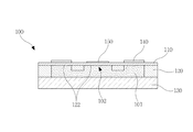
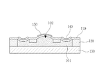
図1は、本発明の第1実施形態による可変焦点光学レンズを示す断面図であり、図2は、図1において、流体レンズ部が凸状に変化された状態を示した断面図である。 FIG. 1 is a cross-sectional view showing a variable focus optical lens according to a first embodiment of the present invention, and FIG. 2 is a cross-sectional view showing a state in which the fluid lens portion is changed into a convex shape in FIG.
図1及び図2を参照すれば、可変焦点光学レンズ100は、メンブレン(membrane)110と、フレーム(frame)120と、基板(substrate)130と、アクチュエータ(actuator)140、及び拘束緩和部150とを含んで構成される。
Referring to FIGS. 1 and 2, the varifocal
メンブレン110は、柔軟な薄膜であって、フレーム120内に収容された光学流体(optical fluid)101の動きによって、その形状が変形される。これにより、後述する流体レンズ部102の曲率を可変させる。ここで、光学流体101は、一定の屈折率と粘性とを有するシリコンオイルなどの物質からなりうる。
The
そして、メンブレン110は、透明な材料からなり、流体レンズ部102に入射する光を透過させる。また、メンブレン110は、基板130とともにフレーム120内に収容された光学流体101を密封可能にする。
The
メンブレン110は、PDMS(polydimethylsiloxane)のような弾性特性に優れて柔軟であり、かつ透明な材料からなりうる。メンブレン110は、フレーム120が四角フレームからなる場合、これに相応するサイズの四角形薄膜からなりうる。
The
フレーム120は、一面に前記メンブレン110が接合される。フレーム120には、光学流体101を収容するように中央に収容ホール122が形成される。そして、フレーム120は、収容ホール122の周りに沿って枠121を有する。フレーム120は、シリコンなどからなりうる。フレーム120は、四角フレームからなりうる。
The
基板130は、フレーム120の他面に接合される。すなわち、基板130は、フレーム120を挟んでメンブレン110の反対側に配されてフレーム120に接合される。これにより、基板130は、メンブレン110とともにフレーム120の収容ホール122に収容された光学流体101を密封可能にする。ここで、基板130は、フレーム120が四角フレームからなる場合、これに相応するサイズの四角形プレートからなりうる。そして、基板130は、透明な材料からなり、光が透過可能にする。基板130は、ガラスなどからなりうる。
The
アクチュエータ140は、収容ホール122の中央部位に生成された流体レンズ部102の周辺を曲げることによって、流体レンズ部102の曲率を可変させる。詳述すれば、アクチュエータ140は、流体レンズ部102の外側で流体レンズ部102の周辺を凹状に曲げてフレーム120内の光学流体101を収容ホール122の中央に移動させる。
The
一方、アクチュエータ140は、流体レンズ部102の外側で流体レンズ部102の周辺を凸状に曲げてフレーム120内の光学流体101を収容ホール122の縁部に移動させる。
On the other hand, the
これにより、収容ホール122の中央部位が凸状になるか、凹状になるか、扁平になりうる。その結果、収容ホール122の中央部位に生成された流体レンズ部102の曲率が変更され、曲率変更による屈折力が負の値または正の値またはゼロの値を有しうる。すなわち、流体レンズ部102の曲率変更による屈折力が負の値と正の値との間の範囲内で可変される。
Thereby, the central part of the
拘束緩和部150は、流体レンズ部102の縁部の拘束力を緩和させるためのものである。拘束緩和部150は、流体レンズ部102より小面積を有し、流体レンズ部102の縁部を除いた流体レンズ部102の内側部位に対応して配される。一例として、拘束緩和部150は、メンブレン110の外側面に配置される。
The
前記拘束緩和部150の直径は、流体レンズ部102の直径より小さく、拘束緩和部150の縁部の端は、流体レンズ部102の周りに沿って流体レンズ部102の縁部の端と一定の間隔を有することが望ましい。これは、流体レンズ部102の縁部の拘束力を流体レンズ部102の周りに沿って均一に緩和させるためである。
The diameter of the
そして、拘束緩和部150は、透明な材料からなる。これは、流体レンズ部102を通過する光を遮断されずに透過させるためである。また、拘束緩和部150は、メンブレン110のヤング率(Young’s modulus)より大きなヤング率を有する。言い換えれば、拘束緩和部150適用部分の変形は、同一な変形量を仮定する時、メンブレン110だけの場合の変形よりさらに大きな応力(stress)が必要である。
And the
これにより、流体レンズ部102が凸状に変化されることによって、拘束緩和部150のないメンブレン110部分と拘束緩和部150とがともに変形される時、拘束緩和部150の変形量が拘束緩和部150のないメンブレン110部分の変形量より小さくなる。したがって、流体レンズ部102で拘束緩和部150が配された中央部位は変形が抑制される一方、拘束緩和部150が配されていない縁部は変形が抑制されなくなる。
As a result, when the
すなわち、拘束緩和部150のない場合と比べて、流体レンズ部102の縁部の拘束力が相対的に緩和される効果が得られる。したがって、流体レンズ部102の形状は、円錐状から球面状に近く変更される。
That is, an effect that the restraining force of the edge portion of the
本実施形態が適用されない場合、可変される流体レンズ部102の形状が円錐状であり、中央の一部分のみ球面状であるために、球面状の流体レンズ部102が必要な光学応用の場合、中央の小領域のみが使用可能である。しかし、本実施形態のように流体レンズ部102の全体形状が球面状になることによって、流体レンズ部102の使用領域が広くなる。したがって、球面状の流体レンズ部102が必要な光学設計に適するようになる。
When this embodiment is not applied, the shape of the
拘束緩和部150は、メンブレン110がPDMSからなる場合、PDMSよりヤング率が大きくて透明なパリレン(parylene)や、ポリウレア(polyurea)や、ポリウレタン(polyurethane)や、テフロン(登録商標)(Teflon)などからなりうる。前記パリレン、ポリウレア、ポリウレタン、テフロン(登録商標)などは弾性特性にも優秀であるので、拘束緩和部150の適用にも有利であり得る。
When the
前記拘束緩和部150のヤング率とメンブレン110のヤング率との差は、大きいほど望ましい。これは、拘束緩和部150の厚さを薄くできるので、可変焦点光学レンズ100のスリム化に有利であるためである。
The larger the difference between the Young's modulus of the
他の例として、図3に示されたように、拘束緩和部150は、メンブレン110の内側面に配されることも可能である。ここで、拘束緩和部150は、前述した例と配置のみ異なり、構成は同一である。また他の例として、図4に示されたように、拘束緩和部150は、メンブレン110の外側面と内側面との両側にすべて配されることも可能である。
As another example, as shown in FIG. 3, the
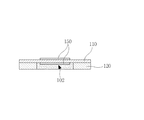
一方、図5に示されたように、フレーム120は、隔壁125をさらに備えることができる。隔壁125は、収容ホール122を中央ホール123と前記中央ホール123の周りに配される複数の縁部ホール124とで区画する。ここで、隔壁125は、メンブレン110側の高さが枠121と同様に形成されて、メンブレン110に接合されうる。
Meanwhile, as shown in FIG. 5, the
そして、隔壁125は、基板130側の高さが枠121より低く形成されて、中央ホール123と縁部ホール124との間が連通されうる。これにより、フレーム120内に収容された光学流体101がアクチュエータ140によって中央ホール123と縁部ホール124との間に自由に移動することができる。
The
流体レンズ部102は、中央ホール123に対応する部位に生成される。そして、アクチュエータ140は、メンブレン110の外側で縁部ホール124に対応する部位にそれぞれ設けられる。アクチュエータ140は、メンブレン110の外側で縁部ホール124に対応する部位を凹状に曲げて縁部ホール124内の光学流体を中央ホール123に移動させる。
The
一方、アクチュエータ140は、流体レンズ部102の外側で縁部ホール124に対応する部位を凸状に曲げて中央ホール123内の光学流体を縁部ホール124に移動させる。
On the other hand, the
これにより、中央ホール123に対応する部位が凸状になるか、凹状になるか、扁平になりうる。したがって、流体レンズ部102の曲率が可変され、曲率変更による屈折力が負の値と正の値との間の範囲内で可変されうる。
Thereby, the site | part corresponding to the
前記アクチュエータ140は、低電力でありながら高速で動作することができることが望ましい。このようなアクチュエータ140としては、一般的なポリマー(polymer)アクチュエータや、圧電(piezoelectric)アクチュエータなどが利用される。
It is desirable that the
ポリマーアクチュエータは、電場によるポリマーの膨張力と収縮力とを用いて変位を発生させる。ここで、ポリマーは、電気活性ポリマー(electro active polymer)、イオン性ポリマー(ionic polymer)などが利用される。 The polymer actuator generates displacement using the expansion force and contraction force of the polymer due to the electric field. Here, as the polymer, an electroactive polymer, an ionic polymer, or the like is used.
圧電アクチュエータは、逆圧電効果による圧電素子の膨張力と収縮力とを用いて変位を発生させる。一方、アクチュエータ140は、光学流体101が中央ホール123の中心方向に均一に流入され、中央ホール123の中心方向から均一に排出されるように設けられることが望ましい。同時に、縁部ホール124は、同一な形状からなることが望ましい。
The piezoelectric actuator generates a displacement by using the expansion force and contraction force of the piezoelectric element due to the inverse piezoelectric effect. On the other hand, it is desirable that the
図6は、本発明の第2実施形態による可変焦点光学レンズを示す断面図であり、図7は、図6において、流体レンズ部が凸状に変化された状態を示した断面図である。本実施形態では、前述した第1実施形態と差がある点について重点的に説明する。 FIG. 6 is a cross-sectional view showing a variable focus optical lens according to a second embodiment of the present invention, and FIG. 7 is a cross-sectional view showing a state in which the fluid lens portion is changed into a convex shape in FIG. In the present embodiment, points that are different from the first embodiment described above will be mainly described.
図6及び図7を参照すれば、本実施形態による可変焦点光学レンズ200は、前述した第1実施形態の拘束緩和部150の代わりに、拘束強化部250を備える。
Referring to FIGS. 6 and 7, the variable focus
拘束強化部250は、流体レンズ部102の縁部の拘束力を強化させるためのものである。拘束強化部250は、流体レンズ部102の中央を除いた縁部を含む領域に対応して配される。一例として、拘束強化部250は、メンブレン110の外側面に配置される。また、拘束強化部250は、内側の直径が流体レンズ部102の直径より小さく、外側の直径が流体レンズ部102の直径より大きく形成される。
The
拘束強化部250の内側の端は、流体レンズ部102の周りに沿って流体レンズ部102の縁部の端と一定の間隔を有することが望ましい。これは、流体レンズ部102の縁部の拘束力を流体レンズ部102の周りに沿って均一に強化させるためである。
It is desirable that the inner end of the
拘束強化部250は、透明な材料からなる。これは、流体レンズ部102を通過する光を遮断されずに透過させるためである。また、拘束強化部250は、メンブレン110のヤング率より大きなヤング率を有する。これにより、拘束強化部250適用部分の変形は、同一な変形量を仮定する時、メンブレン110だけの場合の変形よりさらに大きな応力が必要である。
The
したがって、流体レンズ部102で拘束強化部250が配された縁部を含んだ領域は変形が抑制される一方、拘束強化部250が配されていない中央部位は変形が抑制されなくなる。
Therefore, in the
すなわち、拘束強化部250のない場合と比べて、流体レンズ部102の縁部の拘束力が相対的に強化される効果が得られる。したがって、流体レンズ部102の形状は、さらに鋭い円錐状に変更される。その結果、さらに鋭い円錐状の流体レンズ部102を必要とする光学設計に適するようになる。
That is, the effect of relatively strengthening the restraining force at the edge of the
前記拘束強化部250は、メンブレン110がPDMSからなる場合、PDMSよりヤング率が大きくて透明なパリレンや、ポリウレアや、ポリウレタンや、テフロン(登録商標)などからなりうる。前記ポリレン、ポリウレア、ポリウレタン、テフロン(登録商標)などは弾性特性にも優秀であるので、拘束強化部250の適用にも有利であり得る。
When the
前記拘束強化部250のヤング率とメンブレン110のヤング率との差は、大きいほど望ましい。これは、拘束強化部250の厚さを薄くできるので、可変焦点光学レンズ200のスリム化に有利であるためである。一方、拘束強化部250の内側の端と流体レンズ部102の縁部の端との間の間隔は、流体レンズ部102の円錐状をどの程度鋭く変更するかを設定する変数になりうる。
The larger the difference between the Young's modulus of the
他の例として、図8に示されたように、拘束強化部250は、メンブレン110の内側面に配されることも可能である。ここで、拘束強化部250は、前述した例と配置のみ異なり、構成は同一である。また他の例として、図9に示されたように、拘束強化部250は、メンブレン110の内側面とフレーム120の内壁とにかけて配されることも可能である。また他の例として、図10に示されたように、拘束強化部250は、メンブレン110の外側面と内側面との両側にすべて配されることも可能である。また他の例として、図11に示されたように、拘束強化部250は、メンブレン110の外側面に配されるとともに、メンブレン110の内側面とフレーム120の内壁とにかけて配されることも可能である。
As another example, as shown in FIG. 8, the
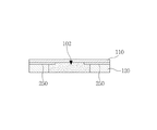
図12は、本発明の第3実施形態による可変焦点光学レンズを示す断面図である。本実施形態では、前述した第1、2実施形態と差がある点について重点的に説明する。 FIG. 12 is a sectional view showing a variable focus optical lens according to a third embodiment of the present invention. In the present embodiment, points that are different from the first and second embodiments will be mainly described.
図12を参照すれば、本実施形態による可変焦点光学レンズ300は、前述した第1実施形態の拘束緩和部150と第2実施形態の拘束強化部250との代わりに、レンズ形状変更部350を備える。
Referring to FIG. 12, the varifocal
レンズ形状変更部350は、流体レンズ部102の形状を設定された形状に変更させるためのものである。レンズ形状変更部350は、流体レンズ部102の少なくとも一部に対応して配される。レンズ形状変更部350は、メンブレン110の外側面と内側面とのうち少なくとも一側面に配置される。
The lens
レンズ形状変更部350は、変更しようとする流体レンズ部102の形状に対応した形状からなりうる。一例として、下で述べるように、流体レンズ部102が凸状に変化されるとき、レンズ形状変更部350は、中央部位に行くほど曲率が小さくなる形状を有してもよい。
The lens
レンズ形状変更部350は、面積が相異なる多数のポリマー層が流体レンズ部102の外側面に積層される。ここで、ポリマー層は、流体レンズ部102の中心と同一軸上に積層されるが、流体レンズ部102から遠くなるほど面積が小さくなるように積層される。すなわち、レンズ形状変更部350は、中央に行くほど順次に厚くなる構造からなるものである。
In the lens
そして、レンズ形状変更部350は、透明な材料からなる。これは、流体レンズ部102を通過する光を遮断されずに透過させるためである。また、レンズ形状変更部350は、メンブレン110のヤング率と同じか、メンブレン110のヤング率より大きなヤング率を有する。これにより、流体レンズ部102が凸状または凹状に変化されることによってメンブレン110とレンズ形状変更部350とがともに変形される時、レンズ形状変更部350の変形量が、レンズ形状変更部350が含まれていないメンブレン110部分の変形量より少なくなるので、メンブレン110の変形が抑制される。
The lens
この際、レンズ形状変更部350で厚い側による抑制効果が、薄い側による抑制効果に比べて大きくなる。したがって、流体レンズ部102は、凸状に変化される時、中央部位に行くほど曲率が小さくなる形状を有しうる。このように流体レンズ部102は、レンズ形状変更部350の形状によってそれに相応する形状を有するようになるので、これを利用すれば、流体レンズ部102を非球面レンズでも具現可能である。したがって、非球面状を要求する光学設計にも適するようになる。
At this time, the suppression effect on the thick side in the lens
前記レンズ形状変更部350は、メンブレンがPDMSからなる場合、メンブレンと同じ物質であるPDMSや、PDMSよりヤング率が大きくて透明なパリレンや、ポリウレアや、ポリウレタンや、テフロン(登録商標)などからなりうる。前記PDMS、ポリレン、ポリウレア、ポリウレタン、テフロン(登録商標)などは弾性特性にも優秀であるので、レンズ形状変更部350の適用にも有利であり得る。
When the membrane is made of PDMS, the lens
前記レンズ形状変更部350のヤング率とメンブレンのヤング率との差は、大きいほど望ましい。これは、レンズ形状変更部350の厚さを薄くできる。同時に、レンズ形状変更部350によって非球面レンズが具現可能であるので、多数のレンズを積層して非球面レンズを具現することに比べて、可変焦点光学レンズ300のスリム化に有利である。
The larger the difference between the Young's modulus of the lens
他の例として、流体レンズ部102を前述した形状と他の形状とに変更させようとすれば、図13に示されたように、レンズ形状変更部450は、リング状を有して面積が相異なる多数のポリマー層が流体レンズ部の外側面に積層される。ここで、ポリマー層は、流体レンズ部102の縁部の周りを取り囲むように積層されるが、流体レンズ部102から遠くなるほど内側空間の面積が大きくなるように積層される。この場合、流体レンズ部102は、凸状に変化される時、縁部の部位が括れた形状を有しうる。
As another example, if the
また他の例として、図14に示されたように、レンズ形状変更部550は、凹凸状を有するように形成される。この場合、流体レンズ部102は、凸状に変化される時、レンズ形状変更部550の凹凸と反対の凹凸状を有しうる。
As another example, as shown in FIG. 14, the lens
また他の例として、図15に示されたように、レンズ形状変更部650は、中央が凸状の形状を有するようになされうる。この場合、流体レンズ部102は、凸状に変化される時、中央部位に行くほど曲率が次第に小さくなる形状を有しうる。
As another example, as illustrated in FIG. 15, the lens
また他の例として、図16に示されたように、レンズ形状変更部750は、中央が凹状の形状を有するように形成される。この場合、流体レンズ部102は凸状に変化される時、中央部位に行くほど曲率が次第に大きくなる形状を有しうる。それ以外に、変更しようとする流体レンズ部102の形状によって、レンズ形状変更部の形状は多様になされうるということは勿論である。
As another example, as shown in FIG. 16, the lens
前記のように構成された本発明の第3実施形態による可変焦点光学レンズ300を製造する方法について、図17Aないし図17Gを参照して説明すれば、次の通りである。ここで、レンズ形状変更部650は、図15に示されたように、中央が凸状である場合を例としてあげる。
A method of manufacturing the variable focus
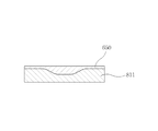
まず、図17Aに示されたように、レンズ形状変更部650を設定された形状に形成するためのモールド811を設ける。この際、レンズ形状変更部650を中央が凸状の形状を有するように形成しようとする場合、モールド811は、上面がレンズ形状変更部650の形状と反対される形状からなる。一方、モールド811の上面には、非粘着(anti−stiction)コーティングができる。これは、後でレンズ形状変更部650が形成された後、モールド811からの分離を容易にさせるためである。
First, as shown in FIG. 17A, a
引き続き、図17Bに示されたように、モールド811上に透明なレンズ形状変更部形成用液状材料812を供給する。この際、レンズ形状変更部形成用液状材料812をドロッピング(dropping)またはディスペンシング(dispensing)工程によってモールド811上に供給することができる。そして、レンズ形状変更部形成用液状材料812としては、パリレンや、ポリウレアや、ポリウレタンや、テフロン(登録商標)などが利用される。
Subsequently, as shown in FIG. 17B, a transparent
引き続き、図17Cに示されたように、モールド811上に供給されたレンズ形状変更部形成用液状材料812の上面を扁平にさせる。この際、アプリケータ(applicator)を用いて、レンズ形状変更部形成用液状材料812の上面を扁平にできる。以後、扁平になったレンズ形状変更部形成用液状材料812を加熱などの過程で硬化させてレンズ形状変更部650を形成する。
Subsequently, as shown in FIG. 17C, the upper surface of the lens shape changing portion forming
引き続き、図17Dに示されたように、形成されたレンズ形状変更部650上に透明なメンブレン形成用液状材料813を供給する。この際、メンブレン形成用液状材料813をドロッピングまたはディスペンシング工程によってレンズ形状変更部650上に供給することができる。そして、メンブレン形成用液状材料813としては、レンズ形状変更部形成用材料812よりヤング率が低い材料が利用される。例えば、レンズ形状変更部形成用液状材料812でパリレンや、ポリウレアや、ポリウレタンや、テフロン(登録商標)が利用されれば、メンブレン形成用液状材料813としてはPDMSが利用される。
Subsequently, as shown in FIG. 17D, a transparent membrane-forming
引き続き、図17Eに示されたように、レンズ形状変更部650上に供給されたメンブレン形成用液状材料813を設定された厚さに扁平にさせた後、硬化させてメンブレン110を形成する。この過程は、レンズ形状変更部650を形成する過程と同様になされうる。
Subsequently, as shown in FIG. 17E, the membrane forming
引き続き、図17Fに示されたように、フレーム120を設けた後、フレーム120をメンブレン110上に接合する。この際、フレーム120を中央に光学流体101が収容される収容ホール122が形成されるように設ける。フレーム120を形成する材料としては、シリコンオイルなどが利用される。一方、フレーム120に形成された整列マークとモールド811に形成された整列マークとを互いに一致させながらフレーム120をメンブレン110に接合させることができる。これは、フレーム120をメンブレン110に対して正確な位置で接合させるためである。
Subsequently, as shown in FIG. 17F, after the
そして、メンブレン110をPDMSで形成し、フレーム120をシリコンで形成する場合、フレーム120をメンブレン110に接合する前に、メンブレン110の接合面に酸素プラズマ処理することができる。これは、メンブレン110を形成するPDMS成分のうちシリコン成分と酸素成分とを除いた成分を酸素プラズマ処理によって除去して、別途の接着剤なしにもフレーム120とメンブレン110との接合が堅固になるようにするためである。
When the
引き続き、図17Gに示されたように、モールド811をレンズ形状変更部650から除去する。この際、以前の過程でモールド811の上面に非粘着コーティングした状態であれば、レンズ形状変更部650をモールド811から容易に分離することができる。
Subsequently, as illustrated in FIG. 17G, the
一方、フレーム120を形成する過程で、図5を参照して前述したように、収容ホール122を中央ホール123と前記中央ホール123の周りに配される複数の縁部ホール124とで区画するための隔壁125をさらに形成することができる。
Meanwhile, in the process of forming the
ここで、隔壁125は、フレーム120がメンブレン110に接合される側の高さをフレーム120の枠121の高さと同様に形成し、フレーム120が基板130に接合される側の高さをフレーム120の枠121の高さより低く形成することができる。これは、フレーム120内に収容された光学流体101を中央ホール123と縁部ホール124との間で自由に移動させるためである。
Here, the
示されていないが、フレーム120とメンブレン110とを接合した後や、モールド811をレンズ形状変更部650から除去した後に、フレーム120の収容ホール122に光学流体101を収容する。光学流体101としては、一定の屈折率と粘性とを有するシリコンオイルなどの物質が利用される。
Although not shown, the
引き続き、フレーム120の収容ホール122に収容された光学流体101が密封されるようにフレーム120でメンブレン110が接合された面の反対側の面に透明な基板130を接着剤などを用いて接合する。
Subsequently, a
引き続き、アクチュエータ140を流体レンズ部102の周辺に付着する。アクチュエータ140は、収容ホール122の中央部位に生成された流体レンズ部102の曲率を可変させるためのものである。この際、流体レンズ部102を中央ホール123に生成する場合、アクチュエータ140をメンブレン110の外側で縁部ホール124に対応してそれぞれ付着することができる。一方、フレーム120に基板130を接合する前に、メンブレン110にアクチュエータ140を付着することも可能であるので、前述した順序に必ずしも限定されるものではない。
Subsequently, the
本発明は、添付した図面に示された一実施形態を参考にして説明されたが、これは例示的なものに過ぎず、当業者ならば、これより多様な変形及び均等な他実施形態が可能であるという点を理解できるであろう。したがって、本発明の真の技術的保護範囲は、特許請求の範囲によって決まるべきである。 Although the present invention has been described with reference to an embodiment shown in the accompanying drawings, this is merely an example, and those skilled in the art will recognize that various modifications and equivalent other embodiments can be made. You will understand that it is possible. Therefore, the true technical protection scope of the present invention should be determined by the claims.
本発明は、無線携帯通信機器などに装着されるカメラモジュールに適用可能な可変焦点光学レンズ関連の技術分野に適用可能である。 The present invention can be applied to a technical field related to a variable focus optical lens applicable to a camera module mounted on a wireless portable communication device or the like.
100 可変焦点光学レンズ、
110 メンブレン、
120 フレーム、
130 基板、
140 アクチュエータ、
150 拘束緩和部、
101 光学流体、
102 流体レンズ部、
122 収容ホール、
121 枠、
125 隔壁、
123 中央ホール、
124 縁部ホール、
200 可変焦点光学レンズ、
150 拘束緩和部、
250 拘束強化部、
300 可変焦点光学レンズ、
350、450、550、650、750 レンズ形状変更部、
811 モールド、
812 液状材料、
813 メンブレン形成用液状材料。
100 variable focus optical lens,
110 membrane,
120 frames,
130 substrates,
140 actuator,
150 restraint relaxation part,
101 optical fluid,
102 Fluid lens part,
122 containment hall,
121 frames,
125 bulkhead,
123 Central Hall,
124 edge hole,
200 variable focus optical lens,
150 restraint relaxation part,
250 restraint strengthening part,
300 variable focus optical lens,
350, 450, 550, 650, 750 Lens shape changing part,
811 mold,
812 liquid material,
813 Liquid material for membrane formation.
Claims (20)
前記メンブレンに接合され、中央に収容ホールが形成されたフレームと、
前記収容ホールに収容された光学流体を密封するように、前記フレームに接合される透明な基板と、
前記収容ホールの中央部位に生成された流体レンズ部の周辺を曲げることによって、前記流体レンズ部の曲率を可変させるアクチュエータと、
透明な材料からなり、前記流体レンズ部より小面積で、前記メンブレンのヤング率(Young’s modulus)より大きなヤング率を有する拘束緩和部と、
を備え、
前記流体レンズ部は、
中央ホールが形成された前記フレームの中央部と、
当該フレームの中央部に接合されて前記中央ホールを塞ぐ前記メンブレンの中央部と、
前記中央ホールにおいて前記メンブレンの中央部によって密封された前記光学流体と、を有し、
前記フレームの中央部では、前記メンブレンに対し、変形を拘束する拘束力が作用し、
前記拘束緩和部は、前記中央ホールの中央で前記メンブレンの表面に配置されることによって、前記中央よりも外側の前記中央ホールの周縁を含む領域において、前記拘束力を相対的に緩和する、可変焦点光学レンズ。 A membrane,
A frame bonded to the membrane and having an accommodation hole formed in the center;
A transparent substrate bonded to the frame so as to seal the optical fluid accommodated in the accommodation hole;
An actuator that varies the curvature of the fluid lens unit by bending the periphery of the fluid lens unit generated in the central portion of the accommodation hole;
And Toru made bright material, wherein a smaller area than the fluid lens unit, restraining absorbing portions having larger Young's modulus than the Young's modulus of the membrane (Young's modulus),
Equipped with a,
The fluid lens portion is
A central portion of the frame in which a central hole is formed;
A central portion of the membrane that is bonded to the central portion of the frame and closes the central hole;
The optical fluid sealed by the central portion of the membrane in the central hole,
In the central part of the frame, a restraining force that restrains deformation acts on the membrane,
The restraint relaxation part is arranged on the surface of the membrane at the center of the center hole, so that the restraint force is relatively relaxed in a region including the periphery of the center hole outside the center. Focus optical lens.
前記隔壁は、前記フレームにおける、前記メンブレンとの接合面を基準として、前記基板側の高さが前記フレームの枠より低く形成されて、前記中央ホールと縁部ホールとの間を連通させることを特徴とする請求項1〜請求項4のいずれか1つに記載の可変焦点光学レンズ。 The frame further includes a partition wall that divides the receiving hole into a central hole in which the fluid lens unit is generated and a plurality of edge holes that are arranged around the central hole and are respectively provided with the actuators. Prepared,
The partition is formed such that the height of the substrate side is lower than the frame of the frame on the basis of the joint surface of the frame with the membrane, and communicates between the center hole and the edge hole. The varifocal optical lens according to claim 1, wherein the varifocal optical lens is characterized in that:
前記メンブレンに接合され、中央に収容ホールが形成されたフレームと、
前記収容ホールに収容された光学流体を密封するように、前記フレームに接合される透明な基板と、
前記収容ホールの中央部位に生成された流体レンズ部の周辺を曲げることによって、前記流体レンズ部の曲率を可変させるアクチュエータと、
透明な材料からなり、前記メンブレンのヤング率より大きなヤング率を有する、前記アクチュエータとは別に設けられた拘束強化部と、
を備え、
前記流体レンズ部は、
中央ホールが形成された前記フレームの中央部と、
当該フレームの中央部に接合されて前記中央ホールを塞ぐ前記メンブレンの中央部と、
前記中央ホールにおいて前記メンブレンの中央部によって密封された前記光学流体と、を有し、
前記フレームの中央部では、前記メンブレンに対し、変形を拘束する拘束力が作用し、
前記拘束強化部は、前記中央ホールの中央よりも外側の前記中央ホールの周縁を含む領域で前記メンブレンの表面に配置されることによって、前記中央ホールの周縁を含む前記領域において、前記拘束力を相対的に強化する、可変焦点光学レンズ。 A membrane,
A frame bonded to the membrane and having an accommodation hole formed in the center;
A transparent substrate bonded to the frame so as to seal the optical fluid accommodated in the accommodation hole;
An actuator that varies the curvature of the fluid lens unit by bending the periphery of the fluid lens unit generated in the central portion of the accommodation hole;
Consists transparency material, prior SL has a larger Young's modulus than the Young's modulus of the membrane, and the restraining reinforcing portion provided separately from the actuator,
Equipped with a,
The fluid lens portion is
A central portion of the frame in which a central hole is formed;
A central portion of the membrane that is bonded to the central portion of the frame and closes the central hole;
The optical fluid sealed by the central portion of the membrane in the central hole,
In the central part of the frame, a restraining force that restrains deformation acts on the membrane,
The restraint strengthening portion is disposed on the surface of the membrane in a region including a peripheral edge of the central hole outside the center of the central hole, so that the restraining force is applied in the region including the peripheral edge of the central hole. A variable focus optical lens that strengthens relatively .
前記隔壁は、前記フレームにおける、前記メンブレンとの接合面を基準として、前記基板側の高さが前記フレームの枠より低く形成されて、前記中央ホールと縁部ホールとの間を連通させることを特徴とする請求項6〜請求項10のいずれか1つに記載の可変焦点光学レンズ。 The frame further includes a partition wall that divides the receiving hole into a central hole in which the fluid lens unit is generated and a plurality of edge holes that are arranged around the central hole and are respectively provided with the actuators. Prepared,
The partition is formed such that the height of the substrate side is lower than the frame of the frame on the basis of the joint surface of the frame with the membrane, and communicates between the center hole and the edge hole. The varifocal optical lens according to claim 6, wherein the varifocal optical lens is characterized in that:
前記メンブレンに接合され、中央に収容ホールが形成されたフレームと、
前記収容ホールに収容された光学流体を密封するように、前記フレームに接合される透明な基板と、
前記収容ホールの中央部位に生成された流体レンズ部の周辺を曲げることによって、前記流体レンズ部の曲率を可変させるアクチュエータと、
前記流体レンズ部の形状を設定された形状に変更させるためのものであって、透明な材料からなり、前記流体レンズ部に少なくとも一部が対応して配され、前記メンブレンのヤング率より大きなヤング率を有するレンズ形状変更部と、
を備えることを特徴とする可変焦点光学レンズ。 A membrane,
A frame bonded to the membrane and having an accommodation hole formed in the center;
A transparent substrate bonded to the frame so as to seal the optical fluid accommodated in the accommodation hole;
An actuator that varies the curvature of the fluid lens unit by bending the periphery of the fluid lens unit generated in the central portion of the accommodation hole;
Be for changing a shape which is set the shape of the fluid lens unit, made of a transparent material, at least part is disposed corresponding to the fluid lens unit, a large Ri by Young's modulus of the membrane A lens shape changing portion having a Young's modulus;
A variable focus optical lens comprising:
前記隔壁は、前記フレームにおける、前記メンブレンとの接合面を基準として、前記基板側の高さが前記フレームの枠より低く形成されて、前記中央ホールと縁部ホールとの間を連通させることを特徴とする請求項12〜請求項19のいずれか1つに記載の可変焦点光学レンズ。 The frame further includes a partition wall that divides the receiving hole into a central hole in which the fluid lens unit is generated and a plurality of edge holes that are arranged around the central hole and are respectively provided with the actuators. Prepared,
The partition is formed such that the height of the substrate side is lower than the frame of the frame on the basis of the joint surface of the frame with the membrane, and communicates between the center hole and the edge hole. 20. The variable focus optical lens according to claim 12, wherein the varifocal optical lens is characterized in that:
Applications Claiming Priority (2)
| Application Number | Priority Date | Filing Date | Title |
|---|---|---|---|
| KR20080137044A KR101508727B1 (en) | 2008-12-30 | 2008-12-30 | Varifocal optical lens |
| KR10-2008-0137044 | 2008-12-30 |
Publications (2)
| Publication Number | Publication Date |
|---|---|
| JP2010156947A JP2010156947A (en) | 2010-07-15 |
| JP5823091B2 true JP5823091B2 (en) | 2015-11-25 |
Family
ID=42284625
Family Applications (1)
| Application Number | Title | Priority Date | Filing Date |
|---|---|---|---|
| JP2009220972A Active JP5823091B2 (en) | 2008-12-30 | 2009-09-25 | Variable focus optical lens |
Country Status (3)
| Country | Link |
|---|---|
| US (1) | US8300317B2 (en) |
| JP (1) | JP5823091B2 (en) |
| KR (1) | KR101508727B1 (en) |
Families Citing this family (12)
| Publication number | Priority date | Publication date | Assignee | Title |
|---|---|---|---|---|
| FR2938349B1 (en) * | 2008-11-07 | 2011-04-15 | Commissariat Energie Atomique | OPTICAL DEVICE WITH DEFORMABLE MEMBRANE WITH IMPROVED ACTUATION |
| EP2192425A1 (en) * | 2008-11-26 | 2010-06-02 | Samsung Electronics Co., Ltd. | Varifocal lens and method of manufacturing the same |
| DE112010005674B4 (en) * | 2010-07-20 | 2020-10-01 | Fraunhofer-Gesellschaft zur Förderung der angewandten Forschung e.V. | Fluidic Variable Focal Length Optical Lens and Method of Making the Same |
| KR101912092B1 (en) | 2010-10-05 | 2018-10-26 | 삼성전자 주식회사 | Fluidic lens |
| KR101912093B1 (en) * | 2010-10-29 | 2018-10-26 | 삼성전자 주식회사 | Optical apparatus |
| KR101826745B1 (en) | 2010-12-14 | 2018-02-07 | 삼성전자주식회사 | Varifocal lens structure and method of manufacturing the varifocal lens structure, and optical lens module and method of manufacturing the optical lens module |
| KR101804473B1 (en) * | 2010-12-16 | 2017-12-04 | 삼성전자주식회사 | Varifocal lens structure and method of manufacturing the same |
| CN106687830B (en) | 2014-07-18 | 2019-05-10 | 珀莱特股份有限公司 | Piezoelectric actuated optical lens |
| FR3029644B1 (en) * | 2014-12-04 | 2018-01-12 | Webster Capital Llc | AUTOFOCUS CAMERA AND VARIABLE FOCAL OPTICAL DEVICE INTENDED TO BE INTEGRATED WITH SUCH A CAMERA |
| CN107085254A (en) * | 2017-05-09 | 2017-08-22 | 厦门新鸿洲精密科技有限公司 | A kind of mechanism that focusing is realized by changing liquid crystal curvature |
| CN112166361B (en) * | 2018-05-24 | 2022-11-25 | 珀莱特股份有限公司 | Optical element with stress distribution support structure |
| DE102019112224A1 (en) * | 2019-05-10 | 2020-11-12 | Carl Zeiss Smt Gmbh | Support of an optical element |
Family Cites Families (18)
| Publication number | Priority date | Publication date | Assignee | Title |
|---|---|---|---|---|
| JPS60220301A (en) | 1984-04-17 | 1985-11-05 | Canon Inc | Variable focus optical element |
| JPH06308303A (en) * | 1993-04-19 | 1994-11-04 | Kanagawa Kagaku Gijutsu Akad | Varifocal lens and device for driving it |
| JP2681032B2 (en) * | 1994-07-26 | 1997-11-19 | 山形大学長 | Ferroelectric polymer single crystal, manufacturing method thereof, and piezoelectric element, pyroelectric element and nonlinear optical element using the same |
| US7646544B2 (en) * | 2005-05-14 | 2010-01-12 | Batchko Robert G | Fluidic optical devices |
| JP2005266128A (en) * | 2004-03-17 | 2005-09-29 | Olympus Corp | Optical system and optical apparatus equipped with same |
| WO2005109074A1 (en) | 2004-05-07 | 2005-11-17 | Koninklijke Philips Electronics N.V. | Electrowetting cell and method for driving it |
| US7826145B2 (en) * | 2004-11-05 | 2010-11-02 | The Regents Of The University Of California | Fluidic adaptive lens systems with pumping systems |
| DE602004006005T8 (en) * | 2004-12-16 | 2008-04-10 | Comelec S.A. | Method for producing a device with a plastic membrane and device thus obtained |
| KR100674866B1 (en) | 2005-05-16 | 2007-01-30 | 삼성전기주식회사 | Variable-focus lens and fabrication method thereof |
| KR100723241B1 (en) | 2005-12-29 | 2007-05-29 | 삼성전기주식회사 | Adjustable-focus lens having a plurality of protrusions at one end of fluid chamber |
| JP2008058841A (en) * | 2006-09-02 | 2008-03-13 | Wakayama Univ | Variable shape liquid type varifocal lens |
| JP2008122908A (en) * | 2006-10-16 | 2008-05-29 | Hitachi Chem Co Ltd | Manufacturing method of optical circuit board with adhesive layer, and optical circuit board with adhesive layer |
| KR20080035252A (en) | 2006-10-19 | 2008-04-23 | 동부일렉트로닉스 주식회사 | Liquid lens making focal point in 3-dimensional space |
| KR20080043106A (en) | 2006-11-13 | 2008-05-16 | 삼성전자주식회사 | Optical lens and manufacturing method thereof |
| KR101452011B1 (en) * | 2007-02-12 | 2014-10-21 | 포라이트 에이에스 | Lens assembly |
| FR2919073B1 (en) * | 2007-07-19 | 2010-10-15 | Commissariat Energie Atomique | OPTICAL DEVICE WITH MEANS FOR ACTUATING A COMPACT DEFORMABLE MEMBRANE |
| US20090195882A1 (en) * | 2008-02-05 | 2009-08-06 | Bolle Cristian A | Mechanical lenses |
| CN101604035A (en) * | 2008-06-13 | 2009-12-16 | 鸿富锦精密工业(深圳)有限公司 | Liquid lens and comprise the camera lens module of this liquid lens |
-
2008
- 2008-12-30 KR KR20080137044A patent/KR101508727B1/en active IP Right Grant
-
2009
- 2009-08-17 US US12/542,418 patent/US8300317B2/en active Active
- 2009-09-25 JP JP2009220972A patent/JP5823091B2/en active Active
Also Published As
| Publication number | Publication date |
|---|---|
| JP2010156947A (en) | 2010-07-15 |
| KR20100078705A (en) | 2010-07-08 |
| KR101508727B1 (en) | 2015-04-06 |
| US20100165475A1 (en) | 2010-07-01 |
| US8300317B2 (en) | 2012-10-30 |
Similar Documents
| Publication | Publication Date | Title |
|---|---|---|
| JP5823091B2 (en) | Variable focus optical lens | |
| JP4823137B2 (en) | Optical lens and manufacturing method thereof | |
| KR101403676B1 (en) | Optical Lens and Manufacturing Method Thereof | |
| AU2018294509B2 (en) | Lens assembly for optical image stabilization and focus adjustment | |
| CN105980888B (en) | Optical device for stablizing image | |
| JP5971913B2 (en) | Optical device | |
| JP6767357B2 (en) | Adjustable microlens with variable structural elements | |
| JP4427537B2 (en) | Liquid zoom lens | |
| EP2290410A1 (en) | Fluidic lens and method of manufacturing the same | |
| KR101804473B1 (en) | Varifocal lens structure and method of manufacturing the same | |
| JP7355756B2 (en) | Optical element with stress distribution support structure | |
| US8004771B2 (en) | Varifocal lens and method of manufacturing the same | |
| KR101484527B1 (en) | Variable focus optical device using liquid optical material and fabrication methods thereof | |
| US8902509B2 (en) | Varifocal lens structure, method of manufacturing the varifocal lens structure, optical lens module including the varifocal lens structure, and method of manufacturing the optical lens module | |
| US10795136B2 (en) | Wafer level lens stack, optical system, electronic device and method | |
| KR101675108B1 (en) | Varifocal lens and method for manufacturing the same |
Legal Events
| Date | Code | Title | Description |
|---|---|---|---|
| A621 | Written request for application examination |
Free format text: JAPANESE INTERMEDIATE CODE: A621 Effective date: 20120223 |
|
| A521 | Request for written amendment filed |
Free format text: JAPANESE INTERMEDIATE CODE: A523 Effective date: 20130124 |
|
| A977 | Report on retrieval |
Free format text: JAPANESE INTERMEDIATE CODE: A971007 Effective date: 20130725 |
|
| A131 | Notification of reasons for refusal |
Free format text: JAPANESE INTERMEDIATE CODE: A131 Effective date: 20130730 |
|
| A521 | Request for written amendment filed |
Free format text: JAPANESE INTERMEDIATE CODE: A523 Effective date: 20131030 |
|
| A131 | Notification of reasons for refusal |
Free format text: JAPANESE INTERMEDIATE CODE: A131 Effective date: 20140507 |
|
| A601 | Written request for extension of time |
Free format text: JAPANESE INTERMEDIATE CODE: A601 Effective date: 20140807 |
|
| A602 | Written permission of extension of time |
Free format text: JAPANESE INTERMEDIATE CODE: A602 Effective date: 20140812 |
|
| A521 | Request for written amendment filed |
Free format text: JAPANESE INTERMEDIATE CODE: A523 Effective date: 20140825 |
|
| A131 | Notification of reasons for refusal |
Free format text: JAPANESE INTERMEDIATE CODE: A131 Effective date: 20150120 |
|
| A521 | Request for written amendment filed |
Free format text: JAPANESE INTERMEDIATE CODE: A523 Effective date: 20150416 |
|
| A131 | Notification of reasons for refusal |
Free format text: JAPANESE INTERMEDIATE CODE: A131 Effective date: 20150512 |
|
| A521 | Request for written amendment filed |
Free format text: JAPANESE INTERMEDIATE CODE: A523 Effective date: 20150812 |
|
| TRDD | Decision of grant or rejection written | ||
| A01 | Written decision to grant a patent or to grant a registration (utility model) |
Free format text: JAPANESE INTERMEDIATE CODE: A01 Effective date: 20150908 |
|
| A61 | First payment of annual fees (during grant procedure) |
Free format text: JAPANESE INTERMEDIATE CODE: A61 Effective date: 20151007 |
|
| R150 | Certificate of patent or registration of utility model |
Ref document number: 5823091 Country of ref document: JP Free format text: JAPANESE INTERMEDIATE CODE: R150 |
|
| R250 | Receipt of annual fees |
Free format text: JAPANESE INTERMEDIATE CODE: R250 |
|
| R250 | Receipt of annual fees |
Free format text: JAPANESE INTERMEDIATE CODE: R250 |
|
| R250 | Receipt of annual fees |
Free format text: JAPANESE INTERMEDIATE CODE: R250 |
|
| R250 | Receipt of annual fees |
Free format text: JAPANESE INTERMEDIATE CODE: R250 |
|
| R250 | Receipt of annual fees |
Free format text: JAPANESE INTERMEDIATE CODE: R250 |
|
| R250 | Receipt of annual fees |
Free format text: JAPANESE INTERMEDIATE CODE: R250 |