CN112166361B - Optical element with stress distribution support structure - Google Patents
Optical element with stress distribution support structure Download PDFInfo
- Publication number
- CN112166361B CN112166361B CN201980034896.6A CN201980034896A CN112166361B CN 112166361 B CN112166361 B CN 112166361B CN 201980034896 A CN201980034896 A CN 201980034896A CN 112166361 B CN112166361 B CN 112166361B
- Authority
- CN
- China
- Prior art keywords
- optical
- optical axis
- support structure
- cover
- microns
- Prior art date
- Legal status (The legal status is an assumption and is not a legal conclusion. Google has not performed a legal analysis and makes no representation as to the accuracy of the status listed.)
- Active
Links
Images


Classifications
-
- G—PHYSICS
- G02—OPTICS
- G02B—OPTICAL ELEMENTS, SYSTEMS OR APPARATUS
- G02B13/00—Optical objectives specially designed for the purposes specified below
- G02B13/001—Miniaturised objectives for electronic devices, e.g. portable telephones, webcams, PDAs, small digital cameras
- G02B13/0055—Miniaturised objectives for electronic devices, e.g. portable telephones, webcams, PDAs, small digital cameras employing a special optical element
- G02B13/0075—Miniaturised objectives for electronic devices, e.g. portable telephones, webcams, PDAs, small digital cameras employing a special optical element having an element with variable optical properties
-
- G—PHYSICS
- G02—OPTICS
- G02B—OPTICAL ELEMENTS, SYSTEMS OR APPARATUS
- G02B7/00—Mountings, adjusting means, or light-tight connections, for optical elements
- G02B7/02—Mountings, adjusting means, or light-tight connections, for optical elements for lenses
-
- G—PHYSICS
- G02—OPTICS
- G02B—OPTICAL ELEMENTS, SYSTEMS OR APPARATUS
- G02B26/00—Optical devices or arrangements for the control of light using movable or deformable optical elements
- G02B26/08—Optical devices or arrangements for the control of light using movable or deformable optical elements for controlling the direction of light
- G02B26/0816—Optical devices or arrangements for the control of light using movable or deformable optical elements for controlling the direction of light by means of one or more reflecting elements
- G02B26/0825—Optical devices or arrangements for the control of light using movable or deformable optical elements for controlling the direction of light by means of one or more reflecting elements the reflecting element being a flexible sheet or membrane, e.g. for varying the focus
Landscapes
- Physics & Mathematics (AREA)
- General Physics & Mathematics (AREA)
- Optics & Photonics (AREA)
- Mechanical Light Control Or Optical Switches (AREA)
- Micromachines (AREA)
- Automatic Focus Adjustment (AREA)
- Optical Couplings Of Light Guides (AREA)
- Lenses (AREA)
Abstract
Description
技术领域technical field
本发明涉及光学元件,更具体地说,本发明涉及具有可弯曲的覆盖件以及一个或多个用于使所述可弯曲的覆盖件成形的致动器的光学元件,以及相应的用途,制造所述光学元件的光学设备和方法。The present invention relates to optical elements, and more particularly to optical elements having a bendable cover and one or more actuators for shaping said bendable cover, and corresponding uses, manufacturing Optical devices and methods of the optical element.
背景技术Background technique
对于诸如透镜组件之类的具有可调焦距和最高可能的成像质量,并且抗冲击的光学(微)元件,日益需要低成本、高产量的解决方案。例如,现代移动电话现在配备有微型数码相机模块,并且对光学元件(例如透镜和透镜组件)的质量和成本要求不断提高,而且要求它们具有抗冲击性。越来越多的用于手机和笔记本电脑的微型相机具有自动对焦功能。例如,用于此类应用的透镜系统的设计需要满足大量要求,其中从生产标准一直到简化在相机模块顶部安装透镜的操作。当透镜装置包括诸如在自动聚焦透镜中遇到的可调参数时,这些挑战甚至更大,其中必须调节焦距,例如以适合从透镜到要拍摄的对象的距离。这样的光学元件通常具有复杂的设计,其中包括可移动部分,这使得难以以简单的方式组装光学元件。这种设计的另一个挑战是在提供用于此类用途的合适光学元件(例如透镜组件)时不断增加的需求。使这些光学元件具有抗冲击性尤其具有挑战性,特别是在必须将光学和机械特性保持在较高水平时。There is an increasing need for low-cost, high-volume solutions for impact-resistant optical (micro) elements such as lens assemblies with adjustable focal length and the highest possible image quality. For example, modern mobile phones are now equipped with miniature digital camera modules, and the quality and cost requirements of optical components, such as lenses and lens assemblies, are constantly increasing, and they are required to be shock-resistant. An increasing number of tiny cameras for cell phones and laptops have autofocus. For example, the design of lens systems for such applications needs to meet a large number of requirements, ranging from production standards all the way to ease of mounting the lens on top of the camera module. These challenges are even greater when the lens arrangement includes adjustable parameters such as encountered in autofocus lenses, where the focal length must be adjusted, for example to suit the distance from the lens to the object to be photographed. Such optical elements often have a complex design including movable parts, which makes it difficult to assemble the optical element in a simple manner. Another challenge with such designs is the ever-increasing need to provide suitable optical elements, such as lens assemblies, for such applications. Making these optics shock-resistant is particularly challenging, especially when optical and mechanical properties must be kept at a high level.
存在许多用于制造紧凑的自动聚焦光学元件的解决方案。当前解决方案的问题之一是如何提供良好的抗冲击性,例如在保持良好的光学和机械特性的同时提供例如良好的抗冲击性。There are many solutions for making compact autofocus optics. One of the problems with current solutions is how to provide good impact resistance, eg good impact resistance while maintaining good optical and mechanical properties.
因此,具有改善的抗冲击性的光学元件将是有利的,尤其是诸如具有改善的抗冲击性的可调光学微透镜之类的光学元件是有利的,其中用于实现良好的抗冲击性的装置要求光学和机械特性仅有小幅劣化,甚至没有任何劣化。Therefore, optical elements with improved impact resistance would be advantageous, especially optical elements such as tunable optical microlenses with improved impact resistance, wherein the Devices require little or no degradation in optical and mechanical properties.
发明内容Contents of the invention
本发明的目的是提供一种光学元件,例如可调光学元件,其解决了现有技术的上述问题,例如提供具有改善的抗冲击性的光学元件(例如可调光学元件)。本发明的另一目的是提供现有技术的替代方案。It is an object of the present invention to provide an optical element, such as a tunable optical element, which solves the above-mentioned problems of the prior art, eg provides an optical element, such as a tunable optical element, with improved impact resistance. Another object of the invention is to provide an alternative to the prior art.
因此,本发明的第一方面旨在通过提供一种光学元件来实现上述目的和其他目的,所述光学元件例如是光学透镜,例如可调光学透镜,其限定光轴并包括:Accordingly, a first aspect of the present invention aims to achieve the above and other objects by providing an optical element, such as an optical lens, such as a tunable optical lens, which defines an optical axis and comprises:
-支撑结构,-supporting structure,
-可弯曲的覆盖件,其附接到所述支撑结构上,其中所述可弯曲的覆盖件与所述支撑结构之间的界面限定界面平面,例如正交于所述光轴的界面平面,例如所述光学元件进一步包括至少一个可变形的透明透镜体,其附接到所述可弯曲的覆盖件上,- a bendable cover attached to said support structure, wherein the interface between said bendable cover and said support structure defines an interface plane, for example an interface plane orthogonal to said optical axis, For example said optical element further comprises at least one deformable transparent lens body attached to said bendable cover,
-一个或多个致动器,例如一个或多个压电致动器,其被布置成使所述可弯曲的覆盖件成形为期望的形状,- one or more actuators, such as one or more piezoelectric actuators, arranged to shape said bendable cover into a desired shape,
其中in
-所述界面平面的一侧的所述支撑结构的以下一项或多项- one or more of the following of said support structure on one side of said interface plane
ο在平行于所述光轴的方向上的尺寸,和/或o a dimension in a direction parallel to said optical axis, and/or
ο杨氏模量οYoung's modulus
沿着正交于所述光轴并且与所述光轴相交的线的至少一部分,在远离所述光轴的方向上,逐渐地和/或以多个阶段增加,其中所述线跨越从所述界面的内边缘处的一点到相对于所述光轴更远的一点的范围,increasing gradually and/or in stages in a direction away from the optical axis along at least a portion of a line perpendicular to and intersecting the optical axis, wherein the line spans from the range from a point at the inner edge of the interface to a point farther relative to the optical axis,
和/或其中and/or where
-所述可弯曲的覆盖件在平行于所述光轴的方向上的尺寸- Dimensions of said bendable cover in a direction parallel to said optical axis
ο在所述界面的内边缘处的至少一个第一点处比o at least one first point at the inner edge of the interface than
ο在从所述第一点到所述光轴的线上的至少一个第二点处o at least one second point on a line from said first point to said optical axis
更大,例如大10%或更多,例如大20%或更多,例如大50%或更多,例如大100%或更多,或者大1微米或更多,例如大2微米或更多,例如大5微米或更多,例如大10微米或更多。Larger, such as 10% or more, such as 20% or more, such as 50% or more, such as 100% or more, or 1 micron or more, such as 2 microns or more , such as 5 microns or more, such as 10 microns or more.
本发明特别地但非排他地有利于获得光学元件,例如光学(折射)透镜或反射元件,例如可调微透镜或可调微反射镜,其可以具有改善的抗冲击性和/或改善的承受跌落影响的能力。另一可能的优点是,所提出的解决方案不会显著损害光学特性(例如波前误差和/或透射率和/或可调性,例如可跨越的屈光度范围)和/或机械特性(例如,可弯曲的覆盖件的抗弯刚度)。The invention is particularly, but not exclusively, advantageous for obtaining optical elements, such as optical (refractive) lenses or reflective elements, such as adjustable microlenses or adjustable micromirrors, which may have improved impact resistance and/or improved withstand Ability to fall affected. Another possible advantage is that the proposed solution does not significantly compromise optical properties (e.g. wavefront error and/or transmittance and/or tunability, e.g. spanable diopter range) and/or mechanical properties (e.g., Bending stiffness of the bendable cover).
本发明人洞察到,例如支撑结构内边缘处的机械特性的突变(例如单个突变)可能导致应力过大,例如可弯曲的覆盖件中的应力过大。本发明的特征可以避免这种过大的应力。本发明洞察到,可以有利地重新分配这种突变(奇异性)处的应力,诸如经由逐渐地或以多个阶段改变厚度和/或杨氏模量的结构。The inventors have realized that a sudden change (eg a single sudden change) in the mechanical properties eg at the inner edge of the support structure may lead to excessive stress, eg in a bendable cover. Features of the present invention avoid such excessive stress. The present invention recognizes that stress at such abrupt changes (singularities) can be advantageously redistributed, such as via gradual or multiple stage changes in thickness and/or Young's modulus of the structure.
更具体地,支撑结构可以逐渐地和/或以多个阶段(例如非单阶段功能)增加厚度和/或杨氏模量(例如“弹簧常数”)和/或可弯曲的覆盖件在与支撑结构的接触点处(例如在支撑结构的侧壁处)的厚度比在支撑结构内部(例如更靠近光轴)更厚(即在平行于光轴的方向上具有更大的尺寸)。“厚度”可以理解为“相干材料的厚度”,例如,如果材料中存在间隙,则只有间隙上方的材料构成厚度,而间隙下方的材料不构成厚度。More specifically, the support structure may increase in thickness and/or Young's modulus (e.g., "spring constant") gradually and/or in multiple stages (e.g., not a single-stage function) and/or the bendable cover may be in contact with the support The thickness is thicker (ie has a greater dimension parallel to the optical axis) at the contact points of the structures (eg at the sidewalls of the support structure) than inside the support structure (eg closer to the optical axis). "Thickness" can be understood as "the thickness of the coherent material", for example, if there is a gap in the material, only the material above the gap constitutes the thickness, while the material below the gap does not.
应当理解,界面平面一侧的支撑结构可以包括厚度的逐渐增加和阶梯式增加的组合,即,支撑结构的一部分可通过厚度逐渐增加形成,而支撑结构的另一部分可通过厚度阶梯式增加形成。It should be understood that the support structure on one side of the interface plane may include a combination of gradual and stepped increases in thickness, ie, a portion of the support structure may be formed with a gradual increase in thickness while another portion of the support structure may be formed with a stepped increase in thickness.
厚度和/或杨氏模量通过多个阶段的阶梯式增加可以采取近似于厚度/杨氏模量逐渐增加的形式。因此,多个阶段可包括至少3个或4个阶段,例如至少6个或至少10个阶段,以便近似连续地逐渐增加。如在其他地方指出的,厚度的逐渐增加或近似逐渐增加可以相对于改善的抗冲击性而改善机械特性。等效地,杨氏模量的逐渐增加或近似逐渐增加同样会改善机械特性。厚度/杨氏模量的阶梯式增加近似于厚度/杨氏模量的连续增加。然而,无论增加是采取多个阶段的形式还是连续变化的形式,这两个例子都表现出厚度/杨氏模量的逐渐增加。因此,厚度或杨氏模量的阶梯式增加是厚度(即,在平行于光轴的方向上的尺寸)或杨氏模量的逐渐增加的示例。The stepwise increase in thickness and/or Young's modulus through multiple stages may take a form that approximates a gradual increase in thickness/Young's modulus. Thus, the plurality of stages may comprise at least 3 or 4 stages, such as at least 6 or at least 10 stages, so as to be progressively increased approximately continuously. As noted elsewhere, gradual increases or near gradual increases in thickness can improve mechanical properties relative to improved impact resistance. Equivalently, a gradual increase or near gradual increase in Young's modulus would also improve the mechanical properties. A stepwise increase in thickness/Young's modulus approximates a continuous increase in thickness/Young's modulus. However, both examples exhibit a gradual increase in thickness/Young's modulus, whether the increase takes the form of multiple stages or a continuous change. Thus, a stepwise increase in thickness or Young's modulus is an example of a gradual increase in thickness (ie, a dimension in a direction parallel to the optical axis) or Young's modulus.
例如,支撑结构可以包括与晶圆的正面分开沉积和图案化的不同层的组合。它们可以是不同的材料,使得背面蚀刻的选择性导致期望的阶梯形状。For example, the support structure may comprise a combination of different layers deposited and patterned separately from the front side of the wafer. They can be of different materials such that the selectivity of the backside etch results in the desired step shape.
形成至少增加的厚度的一部分的线的延伸将界面内边缘处的点延伸到相对于光轴距离放置得更远的点。因此,界面内边缘处的点比放置得更远的点更靠近光轴,并且该线在这些点之间延伸。The extension of the line forming at least part of the increased thickness extends the point at the inner edge of the interface to a point which is placed further with respect to the distance of the optical axis. Thus, points at the inner edge of the interface are closer to the optical axis than points placed farther away, and the line extends between these points.
借助于一个或多个致动器使可弯曲的覆盖件成形为期望的形状可以通过由覆盖件上的致动器产生的应力来实现,因此,覆盖件以取决于致动器的应力和位置的变形做出响应。Forming the bendable cover into the desired shape by means of one or more actuators can be achieved by stresses produced by the actuators on the cover, whereby the cover acts in a manner dependent on the stress and position of the actuators. deformation in response.
本发明的可能的优点是,它能够提供支撑结构并将覆盖件放置在其上,然后集成本发明的特征,其中无需进一步的阶段和/或无需在覆盖件的相反位置上(相对于支撑结构)上具有额外的加强元件。因此,本发明可以被视为提供一种简单和/或有效的制造方法(无论支撑结构和/或覆盖件是否被布置成减轻上述应力奇异性问题)。另外的优点是,诸如致动器之类的其他元件可被放置在覆盖件的相反侧(相对于支撑结构),例如不干扰被布置成减轻上述应力奇异性问题的特征。A possible advantage of the present invention is that it is possible to provide a support structure and place the cover on it and then integrate the features of the present invention, wherein no further stages are required and/or no further stages are required on the cover (relative to the support structure). ) with additional strengthening elements. Accordingly, the present invention may be seen as providing a simple and/or efficient method of manufacture (whether or not the support structure and/or cover is arranged to alleviate the above-mentioned stress singularity problem). A further advantage is that other elements such as actuators may be placed on the opposite side of the cover (relative to the support structure), eg without interfering with features arranged to mitigate the stress singularity problem described above.
“光学元件”可以理解为对穿过元件(例如光学透镜之类的元件,例如光学折射透镜)的光起作用(例如操纵),或者对从光学元件(例如反射元件或反射镜之类的光学元件)反射的光起作用的元件。"Optical element" may be understood as acting on (eg manipulating) light passing through an element (eg an element such as an optical lens, eg a refractive lens) Component) The component on which reflected light plays a role.
光学元件通常可以是可调光学元件。“可调”可以理解为,光学元件的焦距是可调的,例如通过改变被布置成使所述可弯曲的覆盖件成形为期望的形状的一个或多个压电致动器的外加电压来致动致动器(例如,其中致动器是压电致动器)。The optical element may typically be a tunable optical element. "Tunable" is understood to mean that the focal length of the optical element is adjustable, for example by changing the applied voltage to one or more piezoelectric actuators arranged to shape the bendable cover into a desired shape. Actuating the actuator (eg, where the actuator is a piezoelectric actuator).
可变形的透明透镜体例如是透明的,可变形的非流体。可变形的非流体透镜体优选地由诸如弹性聚合物材料之类的弹性材料制成。由于透镜体是非流体,因此不需要紧紧的外壳来固定透镜体,并且没有泄漏的风险。透镜体可以由软聚合物制成,该软聚合物可以包括多种不同的材料,例如硅树脂、聚合物凝胶、交联或部分交联的聚合物的聚合物网络,以及可混溶的油或油的组合。非流体透镜体的弹性模量可以大于300Pa,从而避免在正常操作中由于重力而变形。非流体透镜体的折射率可以大于1.3。A deformable transparent lens body is, for example, a transparent, deformable non-fluid. The deformable non-fluid lens body is preferably made of an elastic material such as an elastic polymer material. Since the lens body is non-fluid, no tight housing is required to hold the lens body and there is no risk of leakage. The lens body can be made of a soft polymer that can include a variety of different materials such as silicone, polymer gels, polymer networks of cross-linked or partially cross-linked polymers, and miscible Oil or combination of oils. The modulus of elasticity of the non-fluid lens body may be greater than 300 Pa, so as to avoid deformation due to gravity in normal operation. The refractive index of the non-fluid lens body may be greater than 1.3.
使用软聚合物使得可以制造其中聚合物与空气接触的透镜,从而在调节透镜的焦距时需要少得多的力(例如与聚合物填充整个空腔的情况相比)。这样还能简化制造,因为即使不同的制造步骤位于不同的位置或设施处,该聚合物仍将保留在原位。The use of soft polymers allows the fabrication of lenses in which the polymer is in contact with air, requiring much less force to adjust the focal length of the lens (compared to, for example, the case where the polymer fills the entire cavity). This also simplifies manufacturing, as the polymer will remain in place even if the different manufacturing steps are at different locations or facilities.
“光轴”在本领域中通常被理解为与覆盖件相交(并且,在光学元件是光学透镜的情况下,光轴也被理解为与透镜体相交),例如穿过透镜体和覆盖件。An "optical axis" is generally understood in the art as intersecting the cover (and, where the optical element is an optical lens, also intersecting the lens body), eg passing through the lens body and the cover.
通常,当在本申请内提及的光学特性时,可以理解,光学特性(例如透射率、不透明性、透明性或反射率)适用于在相对于光轴的入射角(AOI)内传播的光,例如通过光学孔径(光学透镜的光学孔径)传播或被光学有效区域(反射元件的光学有效区域)反射,其中入射角在相对于光轴的0至65°,例如0至40°内(例如0°)。光学特性可以理解为在特定波长(例如可见光区域内的任何波长,例如630nm)处的光学特性,和/或特定入射角(例如0°)处的光学特性,,例如在630nm波长处并且在0°入射角处。In general, when referring to an optical property within this application, it is understood that the optical property (such as transmittance, opacity, transparency, or reflectance) applies to light propagating within an angle of incidence (AOI) relative to the optical axis , e.g. propagating through an optical aperture (optical aperture of an optical lens) or reflected by an optically active area (optical active area of a reflective element), where the angle of incidence is within 0 to 65°, e.g. 0 to 40° relative to the optical axis (e.g. 0°). Optical properties can be understood as optical properties at a specific wavelength (eg any wavelength in the visible region, eg 630nm), and/or optical properties at a specific angle of incidence (eg 0°), eg at a wavelength of 630nm and at 0 ° at the angle of incidence.
当提及光学特性的“平均值”时,应被理解为波长范围内和相对于光轴的入射角(AOI)内所述特性的两倍平均值,其中波长范围可以在10nm至1mm内,例如其中波长范围可以对应于以下一项或多项或全部:When referring to the "mean value" of an optical property, it is understood to mean twice the mean value of the stated property over the wavelength range, which may be within 10 nm to 1 mm, and over the angle of incidence (AOI) with respect to the optical axis, For example, the wavelength range may correspond to one or more or all of the following:
-紫外(UV)区域,例如10至380nm,- the ultraviolet (UV) region, for example 10 to 380 nm,
-可见光(VIS)区域(人类感知或视为“光”),例如380至760nm范围内- Visible light (VIS) region (perceived or regarded as "light" by humans), e.g. in the 380 to 760nm range
-近红外(nIR)区域,例如760至2,500nm范围内,- the near infrared (nIR) region, e.g. in the range 760 to 2,500 nm,
-中红外(mIR)区域,例如2.50至10微米范围内,- the mid-infrared (mIR) region, for example in the 2.50 to 10 micron range,
-远红外(fIR)区域,例如10微米至1毫米范围内,- the far infrared (fIR) region, e.g. in the range of 10 microns to 1 mm,
其中AOI为0至65°,例如0至40°,例如0°。Wherein the AOI is 0 to 65°, such as 0 to 40°, such as 0°.
“光学”应被理解为与“光”有关,“光”应被理解为对应于UV、可见光、nIR、mIR和fIR的一个或多个或全部区域内的电磁辐射,例如在可见光区域内。"Optical" is to be understood in relation to "light" which is to be understood as corresponding to electromagnetic radiation in one or more or all of the regions UV, visible, nIR, mIR and fIR, for example in the visible region.
对“透明的”的提及通常是参照光来理解的,即,光穿过透明对象,几乎没有或没有强度损失,例如当光穿过材料(对应于分别为90%和95%的平均透射率)时,平均损失为10%或更少,例如平均损失为5%或更少。References to "transparent" are generally understood with reference to light, i.e., light passing through a transparent object with little or no loss of intensity, such as when light passes through a material (corresponding to an average transmission of 90% and 95%, respectively rate), the average loss is 10% or less, for example, the average loss is 5% or less.
“透射率”,例如镜面透射率或规则透射率,在相对于光学元件(例如光学透镜)的当前透射率上下文中可以理解为以下两者之间的平均(在波长范围内和入射角范围内)比率:"Transmittance", such as specular transmittance or regular transmittance, in the context of the current transmittance relative to an optical element (such as an optical lens) can be understood as the average between (in the range of wavelengths and in the range of angles of incidence )ratio:
-入射到光学透镜上的光;以及- light incident on the optical lens; and
-入射到光学透镜上的一部分光,该部分透射通过光学透镜并在另一侧以镜面(规则)透射光的形式发射。- A portion of light incident on an optical lens, which is transmitted through the optical lens and emitted on the other side as specular (regular) transmitted light.
“侧壁”可以理解为支撑元件或支撑元件的一部分(例如表面),其至少部分地支撑可弯曲的覆盖件,例如在紧挨着或靠近光学有效区域(例如光学孔径)的区域中支撑可弯曲的覆盖件。"Side wall" is to be understood as a support element or a part (such as a surface) of a support element, which at least partially supports a bendable cover, for example in an area next to or close to an optically active area (such as an optical aperture) that supports a flexible Curved cover.
“支撑结构”可以理解为诸如框架之类的结构,其将可弯曲的覆盖件机械地保持在适当位置,诸如固定可弯曲的覆盖件。例如在相机中,支撑结构相对于相机的其余部分固定覆盖件。支撑结构可以是整体的,例如具有朝着光轴向内突出的元件的硅元件,也可以是非整体的(例如由两种或更多种整体材料组成的),例如朝着光轴向内向内突出的硅元件和环氧树脂元件。By "support structure" is understood a structure, such as a frame, which mechanically holds the bendable cover in place, such as secures the bendable cover. For example in a camera, the support structure secures the cover relative to the rest of the camera. The support structure can be monolithic, such as a silicon element with elements protruding inward toward the optical axis, or non-integral (e.g., composed of two or more monolithic materials), such as inwardly toward the optical axis Protruding silicon components and epoxy components.
“环氧树脂”在本领域中是公知的,特别是指固化的环氧树脂最终产物。环氧树脂,也称为聚环氧化物,是一类反应性预聚物和含有环氧基的聚合物。"Epoxy resin" is well known in the art and refers specifically to a cured epoxy resin end product. Epoxy resins, also known as polyepoxides, are a class of reactive prepolymers and polymers containing epoxy groups.
在可能有利的实施例中,可以施加包括液态的、可流动的热固性或UV可固化的(或组合)粘合剂(具有或不具有无机或有机填充材料)或由此类粘合剂组成的环氧树脂,粘合剂在固化开始之前可实现低粘度(例如等于或小于5000mPas(毫帕斯卡秒)的粘度,例如在粘度由于粘合剂中的交联反应增加之前,从室温(例如20℃或293K)到加热时的温度/时间),固化后的杨氏模量等于或大于1GPa。施加的环氧树脂的其他可能的有利特征可以包括以下一项或多项:低收缩率、良好的热稳定性和良好的耐湿性。In potentially advantageous embodiments, adhesives comprising or consisting of liquid, flowable thermosetting or UV curable (or combination) adhesives (with or without inorganic or organic filler materials) can be applied. Epoxy resins, adhesives can achieve low viscosities (e.g. viscosities equal to or less than 5000 mPas (milliPascal seconds)) before curing begins, e.g. from room temperature (e.g. Or 293K) to the temperature/time when heating), the Young's modulus after curing is equal to or greater than 1GPa. Other possible favorable characteristics of the applied epoxy resin may include one or more of the following: low shrinkage, good thermal stability and good moisture resistance.
可弯曲的覆盖件相对较薄,例如相对于支撑结构(和/或透镜体,当存在时)较薄,其中“薄”是指沿着光轴方向的(小)尺寸,例如小于1mm,例如小于0.75mm,例如小于0.5mm,例如[10;40]微米(即10至40微米范围内)。它可以由任何类型的玻璃(例如杨氏模量在10至100GPa之内,例如在20至100GPa之内,例如在20至60GPa之内或30至70GPa之内的玻璃)制成,例如硼磷硅酸盐玻璃(BPSG),例如任何标准类型的玻璃,或其他材料,例如陶瓷玻璃、聚合物、聚合物-无机混合物,例如所谓的防护玻璃或类似于防护玻璃。这些材料在其中可弯曲的覆盖件应该是透明的实施例中尤其重要。“可弯曲的”可以理解为诸如可弯曲的覆盖件之类的元件可被一个或多个致动器弯曲,即,一个或多个致动器的致动可以使元件弯曲。“可弯曲的覆盖件”可以与“覆盖件”互换地使用。The bendable cover is relatively thin, e.g. relative to the support structure (and/or lens body, when present), where "thin" means a (small) dimension along the optical axis, e.g. less than 1 mm, e.g. Less than 0.75 mm, such as less than 0.5 mm, such as [10;40] microns (ie in the range of 10 to 40 microns). It can be made of any type of glass such as a glass with a Young's modulus within 10 to 100 GPa, such as within 20 to 100 GPa, such as within 20 to 60 GPa or within 30 to 70 GPa, such as borophosphorous Silicate glass (BPSG), such as any standard type of glass, or other materials such as ceramic glass, polymers, polymer-inorganic hybrids, such as so-called protective glasses or similar protective glasses. These materials are especially important in embodiments where the flexible cover should be transparent. "Bendable" is understood to mean that an element such as a bendable cover can be bent by one or more actuators, ie actuation of the one or more actuators can cause the element to bend. "Bendable cover" may be used interchangeably with "cover".
在一个实施例中,提出了一种光学元件,其中可弯曲的覆盖件包括杨氏模量为至少10GPa,例如在10至100GPa内,例如在20至100GPa内,例如在20至60GPa或30至70GPa之内的材料或由此类材料组成。这样的优点(例如相对刚性的覆盖件)可以是允许或促进一个或多个压电致动器限定光学有效区域(诸如孔),同时仍然可在光学有效区域(例如孔,尽管没有任何压电致动器)内通过一个或多个压电致动器使覆盖件成形。In one embodiment, an optical element is provided, wherein the bendable cover comprises a Young's modulus of at least 10 GPa, such as within 10 to 100 GPa, such as within 20 to 100 GPa, such as within 20 to 60 GPa or 30 to Materials within 70GPa or consist of such materials. Such an advantage (such as a relatively rigid cover) may be to allow or facilitate one or more piezoelectric actuators to define an optically active area (such as an aperture) while still being able to define an optically active area (such as an aperture) despite the absence of any piezoelectric actuators. Actuator) to shape the cover by one or more piezoelectric actuators.
可弯曲的覆盖件可以是(在光学元件是光学透镜的情况下)可弯曲的透明覆盖件,并且更具体地可以具有The bendable cover may be (in the case where the optical element is an optical lens) a bendable transparent cover and may more particularly have
-98%或更高透光率,和/或-98% or higher light transmittance, and/or
-小于或等于20MPa的应力。- A stress less than or equal to 20 MPa.
例如,这可以在可弯曲的透明覆盖件由玻璃制成的情况下实现。This can be achieved, for example, if the flexible transparent cover is made of glass.
在一个实施例中,提出了一种光学元件,其中可弯曲的覆盖件延伸超过侧壁的内边缘。应当理解,在光学元件是光学透镜的情况下,侧壁的内边缘对应于侧壁的表面,例如侧壁的面向可变形的透镜体的表面。换句话说,可弯曲的覆盖件比侧壁的表面(例如,侧壁的面向光轴的表面(以及可选地,面向可变形的透镜体)更远离光轴延伸。In one embodiment, an optical element is provided wherein the bendable cover extends beyond the inner edge of the side wall. It should be understood that in case the optical element is an optical lens, the inner edge of the side wall corresponds to the surface of the side wall, for example the surface of the side wall facing the deformable lens body. In other words, the bendable cover extends further away from the optical axis than the surface of the side wall (eg, the surface of the side wall facing the optical axis (and optionally, facing the deformable lens body).
“致动器”在本领域中是公知的,并且例如可以是热致动器、静电致动器、磁致动器或压电致动器中的任何一种。An "actuator" is well known in the art and may be, for example, any of a thermal actuator, an electrostatic actuator, a magnetic actuator, or a piezoelectric actuator.
“被布置成使所述可弯曲的覆盖件成形为期望的形状”可以理解为致动器相对于覆盖件的形状、尺寸和位置使得它们能够在致动时,例如(在压电致动器的情况下)当在其电极上施加电压时,使所述可弯曲的覆盖件变形并因此成形为期望的形状。应当理解,覆盖件的至少一部分在光学有效区域(例如光学孔径)中,例如覆盖件的与光轴相交的部分被成形为期望的形状。"Arranged to shape said bendable cover into a desired shape" is understood to mean that the actuators are shaped, sized and positioned relative to the cover such that they can be actuated, for example (in piezoelectric actuators In the case of ) when a voltage is applied across its electrodes, the bendable cover is deformed and thus shaped into the desired shape. It should be appreciated that at least a portion of the cover is shaped into a desired shape in the optically active area (eg, the optical aperture), eg, the portion of the cover that intersects the optical axis.
“期望的形状”可以理解为当从一种形状变为期望的形状(诸如从一种期望的形状变为另一种期望的形状)时,光学元件的焦距可以改变。By "desired shape" it is understood that the focal length of the optical element may change when changing from one shape to a desired shape, such as from one desired shape to another.
可以通过布置支撑结构,使得界面平面一侧的支撑结构的以下一项或多项Support structures can be arranged so that one or more of the following support structures on one side of the interface plane
ο在平行于光轴的方向上的尺寸,和/或o a dimension in a direction parallel to the optical axis, and/or
ο杨氏模量οYoung's modulus
沿着正交于光轴并且与光轴相交的线的至少一部分,在远离光轴的方向上,逐渐地和/或以多个阶段增加来减轻应力奇异性问题,其中所述线跨越从界面的内边缘处的一点到相对于光轴更远的一点的范围。通过这种布置,如可弯曲的覆盖件所看到的,支撑结构的“弹簧常数”(其中“弹簧常数”被理解为与力F和位移x相关的常数k,例如根据胡克定律,F=kx)可以从光轴上的零开始变化(其中没有支撑结构),并在远离光轴的方向上(例如至少从覆盖件与支撑结构盖之间的界面的内边缘开始)逐渐地或以多个阶段增加。因此,支撑结构与覆盖件之间的最大反作用力的变化也可以在远离光轴的方向上逐渐地或以多个阶段增加。mitigating the stress singularity problem by increasing gradually and/or in stages in a direction away from the optical axis along at least a portion of a line orthogonal to and intersecting the optical axis, wherein the line spans from the interface The range from a point on the inner edge to a point further away from the optical axis. With this arrangement, as seen by the bendable cover, the "spring constant" of the support structure (where "spring constant" is understood as a constant k related to force F and displacement x, e.g. according to Hooke's law, F = kx) can start from zero on the optical axis (where there is no support structure), and gradually or in a direction away from the optical axis (for example, starting at least from the inner edge of the interface between the cover and the support structure cover) Multiple stages added. Thus, the variation of the maximum reaction force between the support structure and the cover can also increase gradually or in stages in a direction away from the optical axis.
请注意,沿着其测量厚度的线段的位置是相对于光轴在径向上向外取向的线段,该线段从支撑结构与覆盖件之间的第一接触点开始,覆盖支撑结构的至少一部分(在径向上位于所述第一接触点的外侧),并且终止于相对于光轴比所述第一接触点更远的点。所述线段的长度可以等于或小于1mm,例如等于或小于750μm,例如等于或小于500μm,例如等于或小于400μm,例如等于或小于300μm,例如等于或小于290μm,例如等于或小于250μm,例如等于或小于200μm,例如等于或小于150μm,例如等于或小于100μm,例如等于或小于50μm,例如等于或小于40μm,例如等于或小于20μm,例如等于或小于10μm,例如等于或小于2μm。支撑结构在所述线段上的厚度,例如在平行于光轴的方向上的尺寸,可以等于或小于1mm,例如等于或小于750μm,例如等于或小于500μm,例如等于或小于400μm,例如等于或小于300μm,例如等于或小于290μm,例如等于或小于250μm,例如等于或小于200μm,例如等于或小于150μm,例如等于或小于100μm,例如等于或小于50μm,例如等于或小于小于40μm,例如等于或小于20μm,例如等于或小于10μm,例如等于或小于2μm。在特定实施例中,所述线段的长度和跨所述线段的支撑结构的尺寸两者可以等于或小于1mm,例如等于或小于750μm,例如等于或小于小于500μm,例如等于或小于400μm,例如等于或小于300μm,例如等于或小于290μm,例如等于或小于250μm,例如等于或小于200μm,例如等于或小于150μm,例如等于或小于100μm,例如等于或小于50μm,例如等于或小于40μm,例如等于或小于20μm,例如等于或小于10μm,例如等于或小于2μm。Note that the location of the line segment along which the thickness is measured is the segment oriented radially outward relative to the optical axis, starting from the first point of contact between the support structure and the cover, covering at least a portion of the support structure ( radially outside of said first contact point) and terminate at a point further with respect to the optical axis than said first contact point. The length of the line segment may be equal to or less than 1 mm, for example equal to or less than 750 μm, for example equal to or less than 500 μm, for example equal to or less than 400 μm, for example equal to or less than 300 μm, for example equal to or less than 290 μm, for example equal to or less than 250 μm, for example equal to or Less than 200 μm, such as 150 μm or less, such as 100 μm or less, such as 50 μm or less, such as 40 μm or less, such as 20 μm or less, such as 10 μm or less, such as 2 μm or less. The thickness of the support structure on said line segment, for example the dimension in the direction parallel to the optical axis, may be equal to or less than 1 mm, for example equal to or less than 750 μm, for example equal to or less than 500 μm, for example equal to or less than 400 μm, for example equal to or less 300 μm, such as equal to or less than 290 μm, such as equal to or less than 250 μm, such as equal to or less than 200 μm, such as equal to or less than 150 μm, such as equal to or less than 100 μm, such as equal to or less than 50 μm, such as equal to or less than 40 μm, such as equal to or less than 20 μm , eg equal to or less than 10 μm, eg equal to or less than 2 μm. In particular embodiments, both the length of the line segment and the size of the support structure across the line segment may be equal to or less than 1 mm, such as equal to or less than 750 μm, such as equal to or less than 500 μm, such as equal to or less than 400 μm, such as equal to or less than 300 μm, such as equal to or less than 290 μm, such as equal to or less than 250 μm, such as equal to or less than 200 μm, such as equal to or less than 150 μm, such as equal to or less than 100 μm, such as equal to or less than 50 μm, such as equal to or less than 40 μm, such as equal to or less 20 μm, eg equal to or less than 10 μm, eg equal to or less than 2 μm.
“支撑结构的杨氏模量”被理解为支撑结构的材料的杨氏模量。“逐渐地和/或以多个阶段增加”就杨氏模量而言可以理解为相对地增加,例如大于或等于10%,大于或等于20%,大于或等于50%或大于或等于100%。By "Young's modulus of the support structure" is understood the Young's modulus of the material of the support structure. "Gradually and/or in stages" is understood in relation to Young's modulus as relative increases, for example greater than or equal to 10%, greater than or equal to 20%, greater than or equal to 50% or greater than or equal to 100% .
“逐渐地和/或以多个阶段增加”就尺寸而言可以理解为绝对地增加。所述增加可以是1微米或更大,例如2微米或更大,例如5微米或更大,例如10微米或更大,例如20微米或更大,例如40微米或更大,例如50微米或更大。所述增加可以是100微米或更小,例如50微米或更小,例如40微米或更小,例如20微米或更小,例如10微米或更小,例如5微米或更小。在特定实施例中,所述增加在1微米至100微米范围内,例如在10微米至100微米范围内,例如在10微米至50微米范围内,例如在20微米至40微米范围内。"Gradually and/or in stages" is understood to mean an absolute increase with respect to size. The increase may be 1 micron or greater, such as 2 microns or greater, such as 5 microns or greater, such as 10 microns or greater, such as 20 microns or greater, such as 40 microns or greater, such as 50 microns or bigger. The increase may be 100 microns or less, such as 50 microns or less, such as 40 microns or less, such as 20 microns or less, such as 10 microns or less, such as 5 microns or less. In a particular embodiment, the increase is in the range of 1 micron to 100 microns, such as in the range of 10 microns to 100 microns, such as in the range of 10 microns to 50 microns, such as in the range of 20 microns to 40 microns.
界面的内边缘处的点与相对于光轴更远地放置的点之间的距离可以是1微米或更大,例如2微米或更大,例如5微米或更大,例如10微米或更大,例如20微米或更大,例如40微米或更大,例如50微米或更大。界面的内边缘处的点与相对于光轴更远地放置的点之间的距离可以是100微米或更小,例如50微米或更小,例如40微米或更小,例如20微米或更小,例如10微米或更小,例如5微米或更小。在特定实施例中,所述距离在1微米至100微米范围内,例如在10微米至100微米范围内,例如在10微米至50微米范围内,例如在20微米至40微米范围内。The distance between a point at the inner edge of the interface and a point placed further from the optical axis may be 1 micron or greater, such as 2 microns or greater, such as 5 microns or greater, such as 10 microns or greater , such as 20 microns or greater, such as 40 microns or greater, such as 50 microns or greater. The distance between a point at the inner edge of the interface and a point placed further from the optical axis may be 100 microns or less, such as 50 microns or less, such as 40 microns or less, such as 20 microns or less , such as 10 microns or less, such as 5 microns or less. In a particular embodiment, the distance is in the range of 1 micron to 100 microns, such as in the range of 10 microns to 100 microns, such as in the range of 10 microns to 50 microns, such as in the range of 20 microns to 40 microns.
在又一更特定的实施例中,平行于光轴的方向上的尺寸的所述增加在1微米至100微米范围内,例如在10微米至100微米范围内,例如在10微米至50微米范围内,例如在20微米至40微米范围内,并且所述距离在1微米至100微米范围内,例如在10微米至100微米范围内,例如在10微米至50微米范围内,例如在20微米至40微米范围内。在又一更特定的实施例中,所述增加在10微米至100微米范围内,并且所述距离在10微米至100微米范围内。在又一更特定的实施例中,所述增加在20微米至40微米范围内,并且所述距离在20微米至40微米范围内。In yet another more particular embodiment, said increase in dimension in a direction parallel to the optical axis is in the range of 1 micron to 100 microns, for example in the range of 10 microns to 100 microns, for example in the range of 10 microns to 50 microns Within, such as in the range of 20 microns to 40 microns, and the distance is in the range of 1 micron to 100 microns, such as in the range of 10 microns to 100 microns, such as in the range of 10 microns to 50 microns, such as in the range of 20 microns to 100 microns in the range of 40 microns. In yet another more specific embodiment, said increase is in the range of 10 microns to 100 microns, and said distance is in the range of 10 microns to 100 microns. In yet another more specific embodiment, said increase is in the range of 20 microns to 40 microns, and said distance is in the range of 20 microns to 40 microns.
通过布置可弯曲的覆盖件以使可弯曲的覆盖件在平行于光轴的方向上的尺寸(例如厚度)By arranging the bendable cover such that the dimension (eg thickness) of the bendable cover in a direction parallel to the optical axis
ο在界面的内边缘处的至少一个第一点处,比ο at least one first point at the inner edge of the interface, than
ο在所述第一点到光轴的线上的至少一个第二点处更大,来减轻应力奇异性问题。o is larger at at least one second point on the line from said first point to the optical axis, to alleviate the stress singularity problem.
通过这种布置,可弯曲的覆盖件可以经历支撑结构的“弹簧常数”的突变,但是在该突变处,它可以足够厚,从而能够处理这种情况,但是同时在支撑结构内的区域处可能足够薄,从而展现出良好的光学和/或机械特性。上述界面是在平行于光轴的方向上观察到的支撑结构与可弯曲的覆盖件之间的界面。With this arrangement, the bendable cover can experience a sudden change in the "spring constant" of the support structure, but at that sudden change it can be thick enough to be able to handle this, but at the same time at areas within the support structure it may Thin enough to exhibit good optical and/or mechanical properties. The aforementioned interface is the interface between the support structure and the bendable cover viewed in a direction parallel to the optical axis.
在一个实施例中,提出了一种光学元件,其中该光学元件不包括液体。在一个实施例中,提出了一种光学元件,其中该光学元件是固态或气态的,例如由固态或气态元件组成。在一个实施例中,提出了一种光学元件,其中该光学元件是固态的,例如由固态元件组成。In one embodiment, an optical element is presented, wherein the optical element does not comprise a liquid. In one embodiment, an optical element is presented, wherein the optical element is solid or gaseous, eg consists of a solid state or gaseous element. In one embodiment, an optical element is presented, wherein the optical element is solid state, eg consists of a solid state element.
光学透镜通常可以是微透镜,例如可调微透镜。“微透镜”通常可以理解为这样一种透镜:其中至少一个结构组件的尺寸(例如厚度(在平行于光轴的方向上的尺寸))在1微米至1毫米范围内。在本申请中,对厚度的提及是提及几何厚度(与光学厚度相反)。在一个实施例中,厚度可以是支撑结构(例如,硅,可以是200至800微米)、覆盖件,以及包括电触点的一个或多个压电致动器(大约22微米)的总和。该光学透镜与挪威poLight公司推出的
d1PZT=4mm,d2PZT=1.5mm,wpol.=4.5mm。d1 PZT = 4 mm, d2 PZT = 1.5 mm, w pol. = 4.5 mm.
在一个实施例中,提出了一种光学元件,其中该光学元件的厚度等于或小于1mm,例如等于或小于700微米,例如等于或小于500微米,例如等于或小于450微米,例如等于或小于425微米,例如等于或小于400微米。具有小厚度的可能的优点是允许光学透镜具有非常小的垂直占地面积。该较小的垂直占地面积反过来可选地允许较薄的光学设备(如相机)具有较小的垂直占地面积,因此可以将其集成到比目前允许的更薄的设备(如手机)中。“光学透镜的厚度”可以理解为在平行于光轴的方向上的光学长度的尺寸(例如,相对于光轴正交并且位于光学透镜的任一侧的两个平面之间的距离)。In one embodiment, an optical element is provided, wherein the thickness of the optical element is equal to or less than 1 mm, such as equal to or less than 700 microns, such as equal to or less than 500 microns, such as equal to or less than 450 microns, such as equal to or less than 425 microns microns, for example equal to or less than 400 microns. A possible advantage of having a small thickness is to allow the optical lens to have a very small vertical footprint. This small vertical footprint in turn optionally allows thinner optical devices (such as cameras) to have a smaller vertical footprint and thus can be integrated into thinner devices (such as mobile phones) than currently allowed middle. "The thickness of an optical lens" can be understood as the dimension of the optical length in a direction parallel to the optical axis (eg, the distance between two planes that are orthogonal to the optical axis and located on either side of the optical lens).
在一个实施例中,提出了一种光学元件,其中支撑结构包括:In one embodiment, an optical element is presented, wherein the support structure comprises:
-支撑元件,例如该支撑元件是硅元件,- a support element, for example a silicon element,
-结构元件,例如该结构元件是环氧树脂元件,例如该结构元件的部分或全部比支撑元件更靠近光轴放置,该结构元件邻接- a structural element, e.g. the structural element is an epoxy resin element, e.g. part or all of the structural element is placed closer to the optical axis than the supporting element, the structural element adjoins
ο支撑元件,以及ο support elements, and
ο可弯曲的覆盖件。ο bendable cover.
具有与支撑元件和可弯曲的覆盖件邻接的结构元件的可能的优点在于,过剩地提供具有要求保护的特征的整体支撑结构(这具有挑战性)。例如,有可能在硅中提供具有要求保护的特征的整体支撑结构,但是这样具有挑战性并且可能导致产量降低。引入上述结构元件允许以简单有效的方式提供具有例如基于环氧树脂的结构元件的支撑结构,其中界面平面一侧的(支撑结构的)结构元件在平行于光轴的方向上的尺寸沿着正交于光轴并与光轴相交的线的至少一部分,在远离光轴的方向上逐渐增加。在一个实施例中,所述结构元件在平行于光轴的方向上具有第一尺寸,该尺寸在1微米至300微米范围内,例如在1微米至100微米范围内,例如在10微米至100微米范围内,例如在10微米至50微米范围内,例如在20微米至40微米范围内。在一个实施例中,所述结构元件在相对于光轴的径向上具有第二尺寸,该尺寸在1微米至300微米范围内,例如在1微米至100微米范围内,例如在10微米至100微米范围内,例如在10微米至50微米范围内,例如在20微米至40微米范围内。在一个实施例中,所述结构元件的杨氏模量在0.1至100Gpa范围内,例如在0.1至10Gpa范围,例如在1至10Gpa范围,例如3.5GPa。在又一更特定的实施例中,所述第一方向和第二方向中的每一个都在1微米至300微米范围内,例如在1微米至100微米范围内,例如在10微米至100微米范围内,例如在20微米至40微米范围内,并且杨氏模量在0.1至100GPa范围内,例如在0.1至10GPa范围内,例如在1至10GPa范围内,例如3.5GPa。在又一更特定的实施例中,所述第一方向和第二方向中的每一个都在20微米至40微米范围内,并且所述结构元件的杨氏模量在1至10GPa范围内。A possible advantage of having a structural element adjoining the support element and the bendable cover is that it is redundant to provide a monolithic support structure with the claimed features (which is challenging). For example, it is possible to provide a monolithic support structure in silicon with the claimed features, but doing so is challenging and may result in reduced yields. The introduction of the above-mentioned structural elements allows to provide in a simple and efficient manner a support structure with e.g. At least a portion of the line intersecting and intersecting the optical axis gradually increases in a direction away from the optical axis. In one embodiment, said structural element has a first dimension in a direction parallel to the optical axis, the dimension being in the range of 1 micron to 300 microns, for example in the range of 1 micron to 100 microns, for example in the range of 10 microns to 100 microns In the range of microns, such as in the range of 10 microns to 50 microns, such as in the range of 20 microns to 40 microns. In one embodiment, said structural element has a second dimension in the radial direction with respect to the optical axis, the dimension being in the range of 1 micron to 300 microns, for example in the range of 1 micron to 100 microns, for example in the range of 10 microns to 100 microns In the range of microns, such as in the range of 10 microns to 50 microns, such as in the range of 20 microns to 40 microns. In one embodiment, the Young's modulus of the structural element is in the range of 0.1 to 100 GPa, such as in the range of 0.1 to 10 GPa, such as in the range of 1 to 10 GPa, such as 3.5 GPa. In yet another more specific embodiment, each of said first and second directions is in the range of 1 micron to 300 microns, such as in the range of 1 micron to 100 microns, such as in the range of 10 microns to 100 microns range, such as in the range of 20 microns to 40 microns, and the Young's modulus is in the range of 0.1 to 100 GPa, such as in the range of 0.1 to 10 GPa, such as in the range of 1 to 10 GPa, such as 3.5 GPa. In yet another more particular embodiment, each of said first and second directions is in the range of 20 microns to 40 microns, and said structural element has a Young's modulus in the range of 1 to 10 GPa.
结构元件仅将支撑元件与可弯曲的覆盖件连接,并且结构元件具有面向光轴的外表面。该外表面从支撑元件延伸到可弯曲的覆盖件,并且可以是平面或曲面,例如向内成形或凹形的表面。The structural element only connects the support element with the bendable cover, and the structural element has an outer surface facing the optical axis. The outer surface extends from the support element to the bendable cover and may be a planar or curved surface, eg an inwardly shaped or concave surface.
可以从多种材料中选择结构元件的材料。在实施例中,结构元件材料可以是聚合物。在实施例中,结构元件材料可以是环氧树脂。The material of the structural elements can be selected from a variety of materials. In an embodiment, the structural element material may be a polymer. In an embodiment, the structural element material may be epoxy.
在实施例中,结构元件可以是有机反应性粘合剂。例如,可以将液态结构元件材料放置在支撑元件和/或可弯曲的覆盖件上,然后经由固化(例如其中固化可以是热活化的化学交联反应、水分活化的固化、UV活化的固化或它们的组合)形成(固态)液态结构元件,所述液态结构元件材料例如是液态有机/混合无机/有机粘合剂,这些粘合剂在固化后变成刚性的交联结构,例如丙烯酸、聚氨酯、环氧树脂、聚酰亚胺、氰基丙烯酸酯。In an embodiment, the structural element may be an organic reactive adhesive. For example, a liquid structural element material may be placed on a support element and/or a flexible cover and then cured (for example, where curing may be heat activated chemical crosslinking, moisture activated curing, UV activated curing or their combination) to form (solid) liquid structural elements such as liquid organic/hybrid inorganic/organic adhesives which after curing become rigid cross-linked structures such as acrylic, polyurethane, Epoxy, polyimide, cyanoacrylate.
在实施例中,将填充材料添加到结构元件材料中。可以将填充材料添加到粘合剂中以获得所需的特性,例如:更高的模量,增加的抗断裂性,更好的热稳定性,更好的机械强度或稳定性,或改变未固化状态下的流动特性。填充材料可以是颗粒、纤维、薄片的形式,并且可以是任何种类的无机(或在某些情况下为有机)矿物(氧化物、氮化物、金属、玻璃、碳)。填充材料可以是各向异性的或各向同性的(例如纤维与球形颗粒)。In an embodiment, a filler material is added to the structural element material. Filler materials can be added to the adhesive to achieve desired properties such as: higher modulus, increased fracture resistance, better thermal stability, better mechanical strength or stability, or to alter the Flow properties in the cured state. The filler material can be in the form of granules, fibers, flakes and can be any kind of inorganic (or in some cases organic) minerals (oxides, nitrides, metals, glass, carbon). Filling materials can be anisotropic or isotropic (eg fibers and spherical particles).
在实施例中,结构元件包括无机材料,例如溶胶-凝胶。有许多材料在凝固前可以具有液体状的特性,并且通过化学/热过程变成刚性的高模量材料,例如通常称为“溶胶-凝胶”系统的材料。一些示例包括:分散在水或其他液体中的纳米颗粒陶瓷,其通过凝胶化、干燥(去除溶剂)和烧结等多步骤过程,甚至可能经过第三步结晶步骤。溶胶-凝胶技术可用于生产陶瓷材料(氧化物、氮化物、碳化物)的薄膜。In an embodiment, the structural element comprises an inorganic material, such as a sol-gel. There are many materials that can have liquid-like properties before solidification and become rigid high-modulus materials through chemical/thermal processes, such as those commonly referred to as "sol-gel" systems. Some examples include nanoparticle ceramics dispersed in water or other liquids through a multi-step process of gelation, drying (removal of solvent) and sintering, possibly even a third crystallization step. Sol-gel technology can be used to produce thin films of ceramic materials (oxides, nitrides, carbides).
在实施例中,结构元件包括金属和/或陶瓷,例如由金属和/或陶瓷组成。金属和/或陶瓷可通过适当掩膜,经由溅射(例如经由物理气相沉积(PVD))来施加。In an embodiment, the structural element comprises metal and/or ceramic, for example consists of metal and/or ceramic. Metals and/or ceramics may be applied via sputtering, eg via physical vapor deposition (PVD), through appropriate masks.
在一个实施例中,提出了一种光学元件,其中支撑结构(例如,结构元件)在平行于光学元件的光轴的方向上的尺寸(例如厚度)逐渐地和/或以多个阶段,沿着正交于光轴的线,从光轴开始远离光轴增加。这种情况的可能的优点是,由于可以利用厚度的增加来逐渐地和/或以多个阶段增加支撑结构的弹簧常数,可以使支撑结构的杨氏模量保持恒定,从而减少或消除应力奇异性问题。In one embodiment, an optical element is provided wherein the dimension (e.g. thickness) of the support structure (e.g. structural element) in a direction parallel to the optical axis of the optical element is gradually and/or in multiple stages along the Along the line perpendicular to the optical axis, starting from the optical axis increases away from the optical axis. A possible advantage of this case is that since the increase in thickness can be used to increase the spring constant of the support structure gradually and/or in multiple stages, the Young's modulus of the support structure can be kept constant, thereby reducing or eliminating stress singularities sexual issues.
在一个实施例中,提出了一种光学元件,其中该光学元件在平行于光轴的方向上承受至少5000(五千)g,例如至少10000g,例如至少15000g,例如至少30000g,例如至少50000g的加速度和/或减速度,例如负方向(即,平行于光轴,从覆盖件到支撑结构的方向,这将对应于下落的冲击,其中覆盖件面向重力方向)和/或正方向上的加速度。在这种情况下,“承受”在本上下文中可以理解为由以下项给出的任何一个或多个或全部参数:In one embodiment, an optical element is provided, wherein the optical element is subjected to at least 5000 (five thousand) g in a direction parallel to the optical axis, such as at least 10000 g, such as at least 15000 g, such as at least 30000 g, such as at least 50000 g Acceleration and/or deceleration, for example acceleration in the negative direction (ie parallel to the optical axis, from the cover to the support structure, which would correspond to the impact of a drop with the cover facing the direction of gravity) and/or in the positive direction. In this case, "subject to" is understood in this context to mean any one or more or all of the parameters given by:
-一个或多个致动器在致动时能够使可弯曲的覆盖件变形的整个屈光度范围,- the entire diopter range over which the one or more actuators are capable of deforming the bendable cover when actuated,
-透射率,例如630nm处的透射率,- transmittance, for example at 630nm,
-总波前误差(WFERMS),- total wavefront error (WFE RMS ),
应该在加速和/或减速后保持在由[90;110]%给出的相对于加速和/或减速之前的所述参数的值的区间内(例如±10%)。It should remain within the interval given by [90; 110]% after acceleration and/or deceleration relative to the value of said parameter before acceleration and/or deceleration (eg ±10%).
可承受的加速度至少部分地通过支撑结构来实现,特别是由于厚度和/或杨氏模量的逐渐增加或阶梯式增加。可以通过支撑结构的各种设计来实现加速度规格,该支撑结构可通过具有增加的厚度和/或杨氏模量、不同的杨氏模量值和不同的形状的部件的不同尺寸来设计。Tolerable accelerations are at least partially achieved by the support structure, in particular due to a gradual or stepwise increase in thickness and/or Young's modulus. Acceleration specifications can be achieved through various designs of support structures that can be designed through different dimensions of components with increased thickness and/or Young's modulus, different values of Young's modulus, and different shapes.
在一个实施例(例如具有支撑元件和结构元件的实施例)中,提出了一种光学元件,其中结构元件被放置成邻近(例如邻接)支撑元件与可弯曲的覆盖件之间的子界面,例如在所述子界面的面向光轴的一侧。这种情况的可能的优点(例如,使结构元件位于拐角处,其中具有平行于或基本平行于光轴且面向光轴的侧壁的支撑结构与覆盖件相交,该覆盖件正交于光轴或位于支撑元件与覆盖件之间,并且比支撑元件更靠近光轴延伸)是,在该位置中,结构元件可以帮助减轻应力奇异性问题。前缀“子”(在“子界面”中)可以理解为表示,由于支撑结构与覆盖件之间具有界面,因此结构元件(作为支撑结构的一部分)只能具有该界面的子界面。In one embodiment (e.g. an embodiment having a support element and a structural element), an optical element is provided wherein the structural element is placed adjacent to (e.g. adjacent to) a sub-interface between the support element and the bendable cover, For example on the side of the sub-interface facing the optical axis. Possible advantages of this situation (e.g. having structural elements located at corners where a support structure with side walls parallel or substantially parallel to and facing the optical axis intersect a cover which is orthogonal to the optical axis Or between the support element and the cover, and extending closer to the optical axis than the support element), in this position the structural element can help alleviate stress singularity problems. The prefix "sub" (in "subinterface") is understood to mean that since there is an interface between the support structure and the covering, the structural element (being part of the support structure) can only have a subinterface of this interface.
在一个实施例(例如具有支撑元件和结构元件的实施例)中,提供了一种光学元件,其中结构元件的部分或全部被放置和/或比支撑元件更靠近光轴延伸,至少比支撑元件更靠近光轴延伸例如至少5μm,例如至少10μm,例如至少15μm,例如至少20μm,例如至少30μm,例如至少40μm,例如至少50μm。这种情况的可能的优点是,在该位置中,结构元件可以帮助减轻应力奇异性问题。In one embodiment (such as an embodiment having a support element and a structural element), an optical element is provided wherein part or all of the structural element is positioned and/or extends closer to the optical axis than the support element, at least Extending closer to the optical axis eg at least 5 μm, eg at least 10 μm, eg at least 15 μm, eg at least 20 μm, eg at least 30 μm, eg at least 40 μm, eg at least 50 μm. A possible advantage of this is that in this location the structural element can help alleviate stress singularity problems.
在一个实施例(例如具有支撑元件和结构元件的实施例)中,提出了一种光学元件,其中结构元件包围(例如完全(360度)包围)光学元件的光轴。这种情况的可能的优点是,它可以减轻或克服环绕光轴的应力奇异性问题。In one embodiment, eg with a support element and a structural element, an optical element is proposed, wherein the structural element surrounds, eg completely (360 degrees) surrounds, the optical axis of the optical element. A possible advantage of this situation is that it mitigates or overcomes the stress singularity problem around the optical axis.
在一个实施例(例如具有支撑元件和结构元件的实施例)中,提出了一种光学元件,其中结构元件的材料不同于In one embodiment (such as an embodiment having a support element and a structural element), an optical element is provided, wherein the material of the structural element is different from
-支撑元件的材料,例如支撑元件邻接结构元件的点处的支撑元件的材料,以及- the material of the support element, e.g. the material of the support element at the points where the support element adjoins the structural element, and
-可弯曲的覆盖件的材料,例如支撑元件邻接结构元件的点处的可弯曲的覆盖件的材料。- The material of the bendable cover, eg the material of the bendable cover at the point where the support element abuts the structural element.
在特定实施例中,结构元件的材料(例如环氧树脂)不同于支撑元件的材料(例如硅)和可弯曲的覆盖件的材料(例如玻璃)。在替代实施例中,结构元件的材料不同于支撑元件的材料或可弯曲的覆盖件的材料。In a particular embodiment, the material of the structural element (eg epoxy) is different from the material of the support element (eg silicon) and the material of the bendable cover (eg glass). In an alternative embodiment, the material of the structural element is different from the material of the support element or the material of the bendable cover.
在一个实施例(例如具有支撑元件和结构元件的实施例)中,提出了一种光学元件,其中结构元件包括聚合物,例如由聚合物组成。In one embodiment, eg with a support element and a structural element, an optical element is provided, wherein the structural element comprises, eg consists of, a polymer.
在一个实施例中,提出了一种光学元件,其中结构元件包括环氧树脂,例如由环氧树脂组成。In one embodiment, an optical element is proposed, wherein the structural element comprises, eg consists of, epoxy resin.
在一个实施例中,提出了一种光学元件,其中从光学元件的光轴观察,结构元件的表面是凹形的。因此,当沿垂直于光轴的方向或与光轴成锐角的方向从光轴朝着凹面观察时,看到凹面。这种情况的可能的优点是,可以通过润湿和/或毛细作用力来实现。另一可能的优点可能是,它促进了良好的机械特性,例如在冲击支撑结构的内侧壁和结构元件的内边缘时,可弯曲的覆盖件中的应力集中系数较低。In one embodiment, an optical element is proposed, wherein the surface of the structural element is concave as viewed from the optical axis of the optical element. Thus, a concave surface is seen when viewed from the optical axis towards the concave surface in a direction perpendicular to the optical axis or in a direction at an acute angle to the optical axis. A possible advantage of this is that it can be achieved by wetting and/or capillary forces. Another possible advantage may be that it promotes good mechanical properties, such as a low stress concentration factor in the bendable cover when impacting the inner side walls of the supporting structure and the inner edges of the structural elements.
通常,不仅通过结构元件的凹入表面获得改善抗冲击性的改善的机械特性,而且还可以利用任何曲面或平面(根据第一方面)来获得,只要光轴方向上的支撑结构的厚度从其中支撑结构的该部分最接近光轴的低厚度到支撑结构的侧壁处的较大的最大厚度逐渐变好或阶梯式变化即可。逐渐增加的厚度会影响透射通过逐渐改变的厚度的光,从而产生由光学元件体现的透镜的成像失真。然而,只要透镜不接收通过逐渐增加的厚度透射的光,逐渐增加的厚度对支撑结构的影响就无关紧要。In general, the improved mechanical properties of improved impact resistance are not only obtained by the concave surface of the structural element, but can also be obtained by using any curved or flat surface (according to the first aspect), as long as the thickness of the supporting structure in the direction of the optical axis is derived from A gradual or stepwise change from a low thickness of the part of the support structure closest to the optical axis to a larger maximum thickness at the sidewall of the support structure is sufficient. The progressively increasing thickness affects the light transmitted through the gradually changing thickness, thereby producing image distortion of the lens embodied by the optical element. However, the effect of increasing thickness on the support structure is insignificant as long as the lens does not receive light transmitted through the increasing thickness.
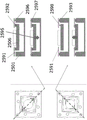
此外,光学孔径111(图1)受压电致动器(层103、104、105)的内边缘限制。光仅穿过孔径。因此,只要支撑结构位于压电致动器的下方,其是否透明就无关紧要。Furthermore, the optical aperture 111 (FIG. 1) is limited by the inner edges of the piezoelectric actuators (
在一个实施例中,提出了一种光学元件,其中光学有效区域的直径是10mm或更小,例如7.5mm或更小,例如5mm或更小(例如[0.5;4.0]mm),例如2.5mm或更小(例如[2.0至2.4]mm),例如1.9mm或更小,例如1.55mm或更小,例如1mm或更小。具有小直径的可能的优点是,它能够提供光学透镜,该光学透镜可以在最终应用设备(例如相机)中利用很小的面积,并且/或者小尺寸有助于将其安装在多个位置以实现其他功能(例如3D成像)。“光学有效区域”可以理解为光可以入射到其上并且可被操纵的区域。对于光学透镜,光学有效区域可对应于光学孔径(例如,与之相同)。对于诸如反射镜之类的反射元件,光学有效区域可以是光可以入射到其上并且可以从中反射被操纵的光的反射区域(例如类似于光学透镜的孔径)。In one embodiment, an optical element is provided, wherein the diameter of the optically active area is 10 mm or less, such as 7.5 mm or less, such as 5 mm or less (eg [0.5; 4.0] mm), such as 2.5 mm or less (eg [2.0 to 2.4] mm), eg 1.9 mm or less, eg 1.55 mm or less, eg 1 mm or less. A possible advantage of having a small diameter is that it can provide an optical lens that can utilize a small area in the end application device (such as a camera) and/or that the small size facilitates its mounting in multiple locations for Implement other functions (such as 3D imaging). An "optically active area" is to be understood as an area on which light can be incident and manipulated. For an optical lens, the optically active area may correspond to (eg, be the same as) the optical aperture. For reflective elements such as mirrors, the optically active area may be a reflective area (eg, similar to an aperture of an optical lens) onto which light may be incident and from which manipulated light may be reflected.
在一个实施例中,提出了一种光学元件,其中光学有效区域的直径是1mm或更大,例如1.55mm或更大,例如1.9mm或更大,例如2mm或更大,例如2.5mm或更大。具有大直径的可能的优点是,它能够提供大量的光。In one embodiment, an optical element is provided, wherein the diameter of the optically active area is 1 mm or more, such as 1.55 mm or more, such as 1.9 mm or more, such as 2 mm or more, such as 2.5 mm or more big. A possible advantage of having a large diameter is that it can provide a large amount of light.
光学元件还可包括至少一个可变形的透明透镜体,该至少一个可变形的透明透镜体附接到可弯曲的覆盖件上。如果光学元件是折射光学元件,例如透镜,例如可调透镜,则这尤其重要。在一个实施例中,提出了一种光学元件,其中该光学元件是折射透镜,其包括:The optical element may also include at least one deformable transparent lens body attached to the bendable cover. This is especially important if the optical element is a refractive optical element, such as a lens, such as a tunable lens. In one embodiment, an optical element is presented, wherein the optical element is a refractive lens comprising:
-被支撑结构的侧壁包围的至少一个可变形的透明透镜体,并且其中可弯曲的覆盖件是附接到- at least one deformable transparent lens surrounded by the side walls of the support structure, and wherein the bendable cover is attached to
ο所述至少一个可变形的透明透镜体的表面的可弯曲的透明覆盖件。o A bendable transparent cover of the surface of said at least one deformable transparent lens body.
在一个实施例中,提出了一种光学元件,其为光学透镜,其中所述至少一个可变形的透明透镜体包括聚合物,诸如固态聚合物,诸如由固态聚合物组成的可变形的透明透镜体。所述至少一个可变形的透明透镜体包括聚合物(例如固态聚合物)可以理解为,所述至少一个可变形的透明透镜体包括至少10重量%(重量百分比),例如至少25重量%,例如至少50重量%,例如至少75重量%的固态聚合物。在一个实施例中,提出了一种光学元件,其为光学透镜,其中所述至少一个可变形的透明透镜体包括交联或部分交联的聚合物的聚合物网络以及可混溶的油或油的组合。在一个实施例中,提出了一种光学元件,其为光学透镜,其中所述至少一个可变形的透明透镜体可以具有大于300Pa的弹性模量,大于1.35的折射率,以及在可见光范围内的吸光率小于每毫米厚度10%。In one embodiment, an optical element is presented, which is an optical lens, wherein said at least one deformable transparent lens body comprises a polymer, such as a solid polymer, such as a deformable transparent lens composed of a solid polymer body. Said at least one deformable transparent lens body comprising a polymer (for example a solid polymer) is understood to mean that said at least one deformable transparent lens body comprises at least 10% by weight (percentage by weight), such as at least 25% by weight, such as At least 50%, such as at least 75%, by weight solid polymer. In one embodiment, an optical element is presented, which is an optical lens, wherein said at least one deformable transparent lens body comprises a polymer network of cross-linked or partially cross-linked polymers and a miscible oil or Combination of oils. In one embodiment, an optical element is proposed, which is an optical lens, wherein the at least one deformable transparent lens body can have an elastic modulus greater than 300Pa, a refractive index greater than 1.35, and a Absorbance is less than 10% per mm thickness.
“折射透镜”在本领域中是公知的,并且被相应地理解。折射透镜的优点是,它们仅需要很少的维护,并且通常不需要准直或重新涂覆到与反射元件相同的程度。"Refracting lenses" are well known in the art and are to be interpreted accordingly. The advantage of refractive lenses is that they require very little maintenance and usually do not need to be collimated or recoated to the same degree as reflective elements.
在一个实施例中,提出了一种光学元件,其中所述光学元件包括一个或多个致动器,用于使可弯曲的覆盖件变形(例如,直接变形)或成形,其中一个或多个致动器和可弯曲的覆盖件被布置成使得一个或多个致动器在致动时能够使可弯曲的覆盖件在整个5屈光度或更大的范围内,例如在整个10屈光度或更大的范围内,例如在整个11屈光度或更大的范围内,例如在整个13屈光度或更大的范围,例如在整个[-3;+10]屈光度或更大的范围内,例如在整个14屈光度或更大的范围内,例如在16屈光度或更大的范围内,例如在17屈光度或更大的范围内,例如在20屈光度或更大的范围内,例如在整个[-10;+20]屈光度或更大的范围内,例如整个28屈光度范围内,例如在整个30屈光度或更大的范围内(例如[-4;+26]屈光度或更大),例如在整个54屈光度或更大的范围内(例如[-4;+50]屈光度或更大)变形或成形。通常可以理解,所跨越的范围可以包括0屈光度或更大的放大倍率,例如跨0至5屈光度或更大的范围,例如0至6屈光度或更大,例如0至7.5屈光度或更大,例如0至10屈光度或更大,例如0至12.5屈光度或更大,例如0至14屈光度或更大,例如0至16屈光度或更大,例如0至20屈光度或更大,例如整个28屈光度或更大的范围,例如整个30屈光度或更大的范围(例如[-4;+26]屈光度或更大),例如整个54屈光度或更大的范围(例如[-4;+50]屈光度或更大)。所跨越的范围可以包括0屈光度和两侧为零的范围的的放大倍率,例如从/至±2.5屈光度或更大的范围(即,从-2.5屈光度至2.5屈光度或更大),例如±6屈光度或更大,例如±7.5屈光度或更大,例如±10屈光度或更大,例如±12.5屈光度或更大,例如±14屈光度或更大,例如±16屈光度或更大,例如±20屈光度或更大,例如[-4;+26]屈光度或更大,例如[-4;+50]屈光度或更大。In one embodiment, an optical element is provided, wherein the optical element comprises one or more actuators for deforming (e.g. direct deformation) or shaping a bendable cover, wherein one or more The actuator and bendable cover are arranged such that the one or more actuators, when actuated, enable the bendable cover to move through a range of 5 diopters or more, such as across 10 diopters or more , such as throughout 11 diopters or greater, such as throughout 13 diopters or greater, such as throughout [-3;+10] diopters or greater, such as throughout 14 diopters or greater, such as within 16 diopters or greater, such as within 17 diopters or greater, such as within 20 diopters or greater, such as throughout [-10; +20] Diopters or greater, such as throughout 28 diopters, such as throughout 30 diopters or greater (eg [-4; +26] diopters or greater), such as throughout 54 diopters or greater Distortion or shaping in the range (eg [-4; +50] diopters or more). It is generally understood that the range spanned may include a magnification of 0 diopters or greater, such as spanning a range of 0 to 5 diopters or greater, such as 0 to 6 diopters or greater, such as 0 to 7.5 diopters or greater, such as 0 to 10 diopters or greater, such as 0 to 12.5 diopters or greater, such as 0 to 14 diopters or greater, such as 0 to 16 diopters or greater, such as 0 to 20 diopters or greater, such as the full 28 diopters or greater A large range, such as the entire 30 diopters or greater (eg [-4; +26] diopters or greater), such as the entire 54 diopters or greater (eg [-4; +50] diopters or greater ). The range spanned may include a magnification of 0 diopters and a range flanked by zeros, such as from/to ±2.5 diopters or greater (i.e., from -2.5 diopters to 2.5 diopters or greater), such as ±6 diopters Diopters or greater, such as ±7.5 diopters or greater, such as ±10 diopters or greater, such as ±12.5 diopters or greater, such as ±14 diopters or greater, such as ±16 diopters or greater, such as ±20 diopters or Greater, such as [-4; +26] diopters or greater, such as [-4; +50] diopters or greater.
“直接”(变形)可以理解为,一个或多个致动器相对于可弯曲的覆盖件布置,使得可弯曲的覆盖件的变形不依赖于第三元件。By "direct" (deformation) it is understood that one or more actuators are arranged relative to the bendable cover such that the deformation of the bendable cover is independent of a third element.
在一个实施例中,提出了一种光学元件,其中:In one embodiment, an optical element is presented, wherein:
-所述光学元件的平均透射率(在波长范围内和入射角范围内)为95%或更高,例如98%或更高,例如99%或更高,和/或- said optical element has an average transmission (over wavelength and angle of incidence) of 95% or higher, such as 98% or higher, such as 99% or higher, and/or
-可见光范围内的最小透射率(例如对于任何可见光波长)例如对于任何可见光波长为94%或更高,和/或- a minimum transmittance in the visible range (eg for any visible wavelength) of eg 94% or higher for any visible wavelength, and/or
-可见光范围内的平均反射率(例如,其中波长范围被限制在任何可见光波长内)为2.5%或更低,例如1%或更低。- an average reflectance in the visible range (for example, where the wavelength range is limited to any visible wavelength) of 2.5% or less, such as 1% or less.
高透射率的优点可以是,其有助于在光穿过光学设备元件传播时减少光损失。在一般实施例中,所述光学透镜具有90%或更高,例如92%或更高,例如93%或更高,例如94%或更高的平均透射率。An advantage of high transmittance may be that it helps reduce light loss as light propagates through optical device elements. In typical embodiments, the optical lens has an average transmittance of 90% or higher, such as 92% or higher, such as 93% or higher, such as 94% or higher.
在一个实施例中,提出了一种光学元件,其中该光学元件是反射元件,并且其中可弯曲的覆盖件在背离支撑结构的一侧和/或在面对支撑结构的一侧是反射的。“反射元件”可以理解为反射入射电磁辐射的元件,例如反射镜。“反射的”可以理解为平均反射率(在波长范围内和入射角范围内)为至少90%,例如至少95%,例如至少99%,例如至少99.9%。反射元件的优点是,与折射光学元件相比,它们受色差的影响较小。反射元件的另一个优点可以是其相对于折射光学组件更轻。In one embodiment, an optical element is proposed, wherein the optical element is a reflective element and wherein the bendable cover is reflective on the side facing away from the support structure and/or on the side facing the support structure. By "reflective element" is understood an element that reflects incident electromagnetic radiation, eg a mirror. "Reflective" is to be understood as meaning an average reflectance (over wavelength and angle of incidence) of at least 90%, such as at least 95%, such as at least 99%, such as at least 99.9%. The advantage of reflective elements is that they are less affected by chromatic aberration than refractive optics. Another advantage of reflective elements may be that they are lighter relative to refractive optics.
在一个实施例中,提出了一种光学元件,其中在整个5屈光度或更大的范围内,例如在整个10屈光度或更大的范围内,例如在整个11屈光度或更大的范围内,例如在整个13屈光度或更大的范围内,例如在整个[-3;+10]屈光度或更大的范围内,例如在整个14屈光度或更大的范围内,例如在整个15屈光度或更大的范围内,总波前误差(WFERMS)等于或小于50nm,例如40nm,例如30nm,例如25nm,例如20nm。在特定实施例中,提出了一种光学元件,其中在整个15屈光度或更大的范围内,总波前误差(WFERMS)等于或小于50nm。在特定实施例中,提出了一种光学元件,其中在整个15屈光度的范围内,总波前误差(WFERMS)等于或小于30nm。通过使整个WFERMS在整个另一个参数范围(例如屈光度)内均低于阈值,将理解,对于给定范围内的其他参数的任何值,总WFERMS均低于阈值。该实施例的可能的优点是,可以在整个屈光度和/或焦距的范围内获得改善的图像质量。“总波前误差(WFERMS)”被理解为总均方根(RMS)波前误差(WFERMS),这在本领域中是公知的,并且被相应地理解。总波前误差(WFE)针对给定的共轭(对象和图像点)定义。波前误差针对光束的每个点定义。波前误差是实际(像差)波前与理想球面波前之间的光程差(OPD),例如光程长度(OPL)的差异。它是通常以纳米(nm)或微米(μm)表示的距离。总波前误差WFERMS针对给定的共轭(对象和图像点)定义。它是表面(在该表面上计算总波前误差)上的光束横截面上的总WFE的均方根,如以下公式中所述:In one embodiment, an optical element is provided wherein over the entire 5 diopters or greater, such as over the entire 10 diopters or greater, such as over the entire 11 diopters or greater, such as Throughout 13 diopters or greater, such as throughout [-3;+10] diopters or greater, such as throughout 14 diopters or greater, such as throughout 15 diopters or greater Within a range, the total wavefront error (WFE RMS ) is equal to or less than 50nm, such as 40nm, such as 30nm, such as 25nm, such as 20nm. In a particular embodiment, an optical element is presented wherein the total wavefront error (WFE RMS ) is equal to or less than 50 nm over a range of 15 diopters or greater. In a particular embodiment, an optical element is presented wherein the total wavefront error (WFE RMS ) is equal to or less than 30 nm over the entire 15 diopters. By having the overall WFE RMS below the threshold throughout another parameter range (eg diopters), it will be understood that the overall WFE RMS is below the threshold for any value of the other parameter within the given range. A possible advantage of this embodiment is that improved image quality can be obtained over the entire range of diopters and/or focal lengths. "Total wavefront error (WFE RMS )" is understood as the total root mean square (RMS) wavefront error (WFE RMS ), which is well known in the art, and is understood accordingly. The total wavefront error (WFE) is defined for a given conjugate (object and image point). The wavefront error is defined for each point of the beam. Wavefront error is the optical path difference (OPD), eg, the difference in optical path length (OPL), between the actual (aberrated) wavefront and the ideal spherical wavefront. It is a distance usually expressed in nanometers (nm) or micrometers (μm). The total wavefront error WFE RMS is defined for a given conjugate (object and image point). It is the root mean square of the total WFE over the beam cross-section on the surface on which the total wavefront error is calculated, as described in the following equation:

在系统的输出光瞳横截面的面积A上进行积分。总WFERMS是单个值。它是通常以纳米(nm)或微米(μm)表示的距离。可以使用带有Shack-Hartmann传感器(例如,总部位于法国奥赛的Imagine Optic公司推出的HASOTM)的波前测量系统执行总WFERMS的测量。在一个实施例中,提出了一种光学元件,其中总波前误差(WFERMS)是在630nm处测量的,例如在630nm的波长处和在0°的入射角处。The integration is performed over the area A of the output pupil cross-section of the system. Total WFE RMS is a single value. It is a distance usually expressed in nanometers (nm) or micrometers (μm). The measurement of the total WFE RMS can be performed using a wavefront measurement system with a Shack-Hartmann sensor (eg HASO ™ from Imagine Optic, Orsay, France). In one embodiment, an optical element is presented wherein the total wavefront error (WFE RMS ) is measured at 630 nm, for example at a wavelength of 630 nm and at an angle of incidence of 0°.
在一个实施例中,支撑结构的杨氏模量小于可弯曲的覆盖件的杨氏模量。例如,支撑结构可包括诸如环氧树脂之类的粘合剂或由其组成,该粘合剂在固化后(例如通过加热或UV固化过程)具有的杨氏模量值为1至20GPa,例如3.5GPa。相比之下,例如由玻璃制成的可弯曲的覆盖件的杨氏模量在10至100Gpa的范围内。例如,硼硅酸盐玻璃的杨氏模量为63GPa,熔融石英玻璃的杨氏模量为73GPa,硼磷硅酸盐玻璃的杨氏模量为44GPa。有利地,具有相对较高的弹性(即,较低的杨氏模量)的支撑结构可以更容易以可靠的方式附接到覆盖件和支撑结构的侧壁上。In one embodiment, the Young's modulus of the support structure is less than the Young's modulus of the bendable cover. For example, the support structure may comprise or consist of an adhesive, such as an epoxy resin, which after curing (e.g. by heating or a UV curing process) has a Young's modulus value of 1 to 20 GPa, e.g. 3.5GPa. In contrast, the Young's modulus of a flexible cover, for example made of glass, is in the range of 10 to 100 GPa. For example, the Young's modulus of borosilicate glass is 63GPa, that of fused silica glass is 73GPa, and that of borophosphosilicate glass is 44GPa. Advantageously, a support structure having a relatively high elasticity (ie a lower Young's modulus) can be more easily attached to the cover and the side walls of the support structure in a reliable manner.
在一个实施例中,多个阶段包括至少4个阶段。有利地,支撑结构的阶梯表面就其机械特性而言近似具有连续结构的支撑结构。In one embodiment, the plurality of stages includes at least 4 stages. Advantageously, the stepped surface of the support structure approximates a support structure with a continuous structure in terms of its mechanical properties.
在一个实施例中,支撑结构的至少一部分与至少一个可变形的透明透镜体间隔开,该支撑结构的至少一部分在平行于光轴的方向上的尺寸和/或杨氏模量逐渐地增加和/或以多个阶段增加。In one embodiment, at least a portion of the support structure is spaced apart from the at least one transparent deformable lens body, the dimension and/or Young's modulus of at least a portion of the support structure in a direction parallel to the optical axis gradually increases and /or increase in multiple stages.
支撑结构的一部分(例如结构元件)可被放置为在最靠近光轴的结构元件部分与距离光轴最远的透镜体部分之间具有径向间隔,该支撑结构的一部分在平行于光轴的方向上的尺寸和/或杨氏模量增加。因此,结构元件可以外接透镜体,使得在沿着结构元件的外周在任何点上,都没有结构元件或支撑结构与透镜体之间的直接接触。A portion of the support structure, such as a structural element, may be placed with a radial separation between the portion of the structural element closest to the optical axis and the portion of the lens body furthest from the optical axis, the portion of the support structure being parallel to the optical axis. direction of dimension and/or Young's modulus increase. Thus, the structural element may circumscribe the lens body such that at any point along the periphery of the structural element there is no direct contact between the structural element or the support structure and the lens body.
有利地,结构元件与透镜体间隔开的布置确保了结构元件不会干扰光在透镜体中的传播。此外,由于结构元件或支撑结构的所述部分与透镜体之间不接触,透镜体不会因为结构元件的变形而承受变形或应力。Advantageously, the spaced arrangement of the structural elements from the lens body ensures that the structural elements do not interfere with the propagation of light in the lens body. Furthermore, since there is no contact between the structural element or said portion of the support structure and the lens body, the lens body is not subject to deformation or stress due to deformation of the structural element.
在一个示例中,结构元件或支撑结构的所述部分可以至少与至少一个可变形的透明透镜体分开,使得结构元件的最接近光轴的部分不延伸到透镜体中。因此,可以允许基本为零(例如几微米)的最小距离。In one example, said portion of the structural element or support structure may be at least separated from the at least one transparent deformable lens body such that the portion of the structural element closest to the optical axis does not extend into the lens body. Therefore, a minimum distance of substantially zero (eg a few micrometers) may be allowed.
第二方面涉及一种用于提供根据第一方面的光学元件的方法。A second aspect relates to a method for providing an optical element according to the first aspect.
在第二方面的实施例中,该方法用于改善光学元件的可弯曲的覆盖件的抗冲击性。In an embodiment of the second aspect, the method is used to improve the impact resistance of a bendable cover for an optical element.
在第二方面的实施例中,提出了一种用于制造根据第一方面,尤其是在第一方面的任何实施例中的光学元件的方法,其中支撑结构包括:In an embodiment of the second aspect there is provided a method for manufacturing an optical element according to the first aspect, in particular in any embodiment of the first aspect, wherein the support structure comprises:
-支撑元件,以及- supporting elements, and
-结构元件,- structural elements,
所述方法包括将液态结构元件材料放置在The method includes placing a liquid structural element material in
-支撑元件,和/或- support elements, and/or
-可弯曲的覆盖件上,- on the bendable cover,
例如,所述方法包括将液态结构元件材料放置在支撑元件与可弯曲的覆盖件之间的界面的内边缘处,从而形成结构元件。For example, the method includes placing a liquid structural element material at the inner edge of the interface between the support element and the bendable cover, thereby forming the structural element.
为了获得结构元件,可以应用诸如固化过程之类的强固工艺以实现液态结构元件材料的期望的机械特性。In order to obtain the structural elements, robust processes such as curing processes can be applied to achieve the desired mechanical properties of the liquid structural element material.
该方法的优点是,将液态材料放置在所述位置处相对简单。另一可能的优点是,可以利用润湿力和/或毛细作用力来重新分配所述液体,这可能有助于提供一种相对简单而有效的方式来获得所要求保护的光学元件。对于环氧树脂(例如光学透镜中的固化环氧树脂)之类的结构元件,液态结构材料可以是未固化的环氧树脂。将液态结构元件材料放置在支撑元件与可弯曲的覆盖件之间的界面的内边缘处的可能的优点是,接着将液态结构元件材料(从头开始)放置在界面上,从该位置开始使用润湿和/或毛细作用力(更容易)重新分配液体。The advantage of this method is that it is relatively simple to place the liquid material at said location. Another possible advantage is that wetting and/or capillary forces can be used to redistribute the liquid, which may help provide a relatively simple and efficient way of obtaining the claimed optical element. For structural elements such as epoxies, such as cured epoxies in optical lenses, the liquid structural material may be uncured epoxy. A possible advantage of placing the liquid structural element material at the inner edge of the interface between the support element and the bendable cover is that the liquid structural element material is then placed (from scratch) on the interface from where the moistening Wet and/or capillary forces (easier) redistribute liquid.
在一个实施例中,提出了一种方法,其中液态结构元件材料经由液态结构元件与In one embodiment, a method is proposed wherein the liquid structural element material is combined with the liquid structural element
-支撑元件,和/或- support elements, and/or
-可弯曲的覆盖件- bendable cover
之间的粘合力重分配为例如沿着支撑元件与可弯曲的覆盖件之间的界面的内边缘超出其放置位置,例如液态结构元件材料经由粘合力在至少100微米,例如至少500微米,例如至少1000微米,例如至少2000微米的距离上重新分配。经由所述粘合力重新分配的可能的优点是,其有助于提供或确保液态结构元件的均匀分配。另一可能的优点是,重新分配是自动执行的。另一可能的优点是,可以通过控制支撑结构和/或可弯曲的覆盖件的表面来控制重新分配。“经由粘合力重新分配”可以理解为润湿和/或毛细作用力。Redistribution of the adhesive force between is for example along the inner edge of the interface between the support element and the bendable cover beyond its placement position, for example the liquid structural element material via the adhesive force at least 100 microns, for example at least 500 microns , eg over a distance of at least 1000 microns, eg at least 2000 microns. A possible advantage of redistribution via said adhesive force is that it helps to provide or ensure an even distribution of the liquid structural element. Another possible advantage is that reallocation is performed automatically. Another possible advantage is that redistribution can be controlled by controlling the support structure and/or the surface of the flexible cover. "Redistribution via adhesive forces" may be understood as wetting and/or capillary forces.
在一个实施例中,提出了一种方法,其中液态结构元件材料经由液态结构元件与In one embodiment, a method is proposed wherein the liquid structural element material is combined with the liquid structural element
-支撑元件,和/或- support elements, and/or
-可弯曲的覆盖件- bendable cover
之间的粘合力重新分配,从而包围(例如完全(360度)包围)光学元件的光轴。The adhesive force between them is redistributed so as to surround (eg completely (360 degrees) surround) the optical axis of the optical element.
在一个实施例中,提出了一种方法,其中该方法还包括固化液态结构元件材料,例如由此形成结构元件。In one embodiment, a method is provided, wherein the method further comprises curing the liquid structural element material, eg forming the structural element thereby.
液态结构元件材料的固化可以包括在液态结构元件沿着可弯曲的覆盖件重新分配之后,液态结构元件的固化过程。Curing of the liquid structural element material may include a curing process of the liquid structural element after redistribution of the liquid structural element along the flexible cover.
根据第三方面,提供了一种相机,包括According to a third aspect, a camera is provided, comprising
-根据第一方面的光学元件,例如其中可弯曲的覆盖件经由支撑结构附接到相机的其余部分上,例如除光学元件之外的相机部分,或者- an optical element according to the first aspect, e.g. wherein the bendable cover is attached via a support structure to the rest of the camera, e.g. a part of the camera other than the optical element, or
-根据第二方面制造的光学元件,例如其中可弯曲的覆盖件经由支撑结构附接到相机的其余部分上,例如除光学元件之外的相机部分。- An optical element manufactured according to the second aspect, for example wherein the bendable cover is attached via a support structure to the rest of the camera, eg the part of the camera other than the optical element.
可以理解,光学元件是相机的一部分。光学元件可以经由支撑结构与相机(即,没有光学元件的相机或相机的其余部分)集成在一起,从而将支撑结构附接到(例如胶粘到)相机的一部分上。这样,可弯曲的覆盖件附接到相机上。It will be understood that the optics are part of the camera. The optical element may be integrated with the camera (ie, the camera without the optical element or the rest of the camera) via the support structure such that the support structure is attached (eg glued) to a part of the camera. In this way, the bendable cover is attached to the camera.
在更一般的实施例中,提供了一种光学设备,其包括In a more general embodiment, there is provided an optical device comprising
-根据第一方面的光学元件,或- an optical element according to the first aspect, or
-根据第二方面制造的光学元件,- an optical element manufactured according to the second aspect,
其中光学设备可以是选自包括以下项(例如由以下项组成)的组的任何一种光学设备:扫描仪、相机、可变光学调谐器或衰减器、虹膜、光学防抖(OIS)单元、变焦镜头、广角镜、条形码读取器、内窥镜、投影仪或任何将光组织起来以产生所需效果(例如成像)的设备。wherein the optical device may be any optical device selected from the group comprising (e.g. consisting of): a scanner, a camera, a variable optical tuner or attenuator, an iris, an optical image stabilization (OIS) unit, Zoom lenses, wide-angle lenses, barcode readers, endoscopes, projectors, or any device that organizes light to produce a desired effect such as imaging.
根据本发明的第四方面,提供了使用According to a fourth aspect of the present invention, there is provided the use of
-根据第一方面的光学元件,或- an optical element according to the first aspect, or
-根据第二方面制造的光学元件,- an optical element manufactured according to the second aspect,
来获取一个或多个图像。在替代实施例中,所提及的光学元件可用于扫描诸如条形码和/或视网膜之类的识别标记,或者用于衰减特定波长的光。to get one or more images. In alternative embodiments, the mentioned optical elements may be used to scan identification marks such as barcodes and/or retinas, or to attenuate specific wavelengths of light.
本发明的第一、第二、第三和第四方面可以分别与任何其他方面组合。本发明的这些和其他方面通过参考下文描述的实施例将变得显而易见并得到阐明。The first, second, third and fourth aspects of the invention may each be combined with any other aspect. These and other aspects of the invention will be apparent from and elucidated with reference to the embodiments described hereinafter.
附图说明Description of drawings
现在将参考附图更详细地描述根据本发明的光学元件、方法、光学设备和用途。附图示出了实现本发明的一种方式,并且不应被解释为限于落入所附权利要求书的范围内的其他可能的实施例。The optical element, method, optical device and use according to the invention will now be described in more detail with reference to the accompanying drawings. The figures show one way of carrying out the invention and should not be construed as limiting to other possible embodiments falling within the scope of the appended claims.
图1是光学元件的透视图。Fig. 1 is a perspective view of an optical element.
图2是光学元件的侧视图。Fig. 2 is a side view of an optical element.
图3是制造方法期间的光学元件的仰视图的显微镜图像。Fig. 3 is a microscope image of a bottom view of an optical element during the manufacturing process.
图4示出了从图1至2示意性地示出的光学元件的背面观察的透视图的显微镜(SEM)图像。Fig. 4 shows a microscopic (SEM) image of a perspective view viewed from the back of the optical element schematically shown in Figs. 1 to 2 .
图5示出了光学元件的仿真模型。Fig. 5 shows the simulation model of the optical element.
图6示出了说明应力奇异性问题的图。Figure 6 shows a graph illustrating the stress singularity problem.
图7至11示出了对应于图5至6中描述的仿真模型的仿真结果。7 to 11 show simulation results corresponding to the simulation models described in FIGS. 5 to 6 .
图12至14示出了其中支撑结构由硅制成的替代实施例。Figures 12 to 14 show an alternative embodiment in which the support structure is made of silicon.
图15示出了对应于图12至14的三个仿真模型的仿真结果,其中Si结构元件的宽度为20μm。FIG. 15 shows the simulation results corresponding to the three simulation models of FIGS. 12 to 14 , where the width of the Si structural element is 20 μm.
图16包括图15和图17的曲线图例。FIG. 16 includes legends for the graphs of FIGS. 15 and 17 .
图17示出了对应于图12至14的三个仿真模型的类似于图15的仿真结果,其中Si结构元件的宽度为40μm。FIG. 17 shows simulation results similar to FIG. 15 corresponding to the three simulation models of FIGS. 12 to 14 , where the width of the Si structural element is 40 μm.
图18是示出光学元件中的位置的示意图。Fig. 18 is a schematic diagram showing positions in an optical element.
图19示出了一个实施例。Figure 19 shows one embodiment.
图20至25提供了替代光学透镜的示例。20 to 25 provide examples of alternative optical lenses.
图26示出了使用环氧树脂作为结构元件的三个仿真模型的类似于图15的仿真结果Figure 26 shows simulation results similar to Figure 15 for three simulation models using epoxy resin as structural elements
具体实施方式Detailed ways
通常,当暗示方向时,例如当使用术语“上方”或“下方”或“顶部”或“底部”时,通常应理解为在平行于光轴的方向上定义了从支撑结构到覆盖件的正方向。例如,覆盖件在支撑结构上方,例如在支撑结构的顶部上。此外,“内部”通常是指元件的面向光轴的一部分,例如元件的一侧或一端,例如具有面向光轴的“内侧”或“内端”或者背离光轴的“外侧”或“外端”的元件。类似地,“内部”(例如“内侧壁”)通常是指元件的面向光轴的一部分,例如元件的一侧或一端,例如具有面向光轴的“内侧壁”或者背离光轴的“外侧壁”的元件。In general, when a direction is implied, for example when the terms "above" or "below" or "top" or "bottom" are used, it is generally understood to define the normal direction from the support structure to the covering in a direction parallel to the optical axis. direction. For example, the cover is over the support structure, eg on top of the support structure. Furthermore, "inner" generally refers to a part of an element facing the optical axis, such as a side or end of an element, for example having an "inner" or "inner end" facing the optical axis or an "outer" or "outer end" facing away from the optical axis. " element. Similarly, "inner" (e.g., "inner sidewall") generally refers to a portion of an element facing the optical axis, such as a side or end of the element, for example having an "inner sidewall" facing the optical axis or an "outer sidewall" facing away from the optical axis " element.
图1是光学元件,更具体地是指根据一个实施例的光学透镜,再具体地是指厚度122在200至800微米的范围内的支撑结构101的透视图。支撑结构具有面向光轴110的内侧壁112。该图还示出了可弯曲的透明覆盖件102(在本实施例中为玻璃)、用于一个或多个致动器(为压电致动器)的底部电极103、压电活性材料104、顶部电极105(用于一个或多个压电致动器)。支撑结构包括:支撑元件126,其中支撑元件126是硅元件;以及结构元件128,其中结构元件128是环氧树脂元件。所有结构元件128都比支撑元件126更靠近光轴放置,并且结构元件128邻接支撑元件126和可弯曲的覆盖件102。支撑元件126具有在100至500微米范围内的宽度124。可以理解,在俯视图中(沿着平行于光轴的方向)观察到的一个或多个压电致动器的位置被定义为其中所有底部电极103、压电活性层104和顶部电极105之间存在重叠的位置(请注意,只有在这些位置才能激活压电活性层)。该图还示出了透明的可变形透镜体107(在本实施例中是聚合物)、透明的后窗106(安装在透镜体107上)、支撑结构101内的腔体108(腔体108包括光轴110并在远离光轴110的方向上被侧壁112界定)、支撑结构101的内边缘109(在支撑结构101与可弯曲的透明覆盖件102的界面处),其朝着底部电极103的表面或顶部电极105的表面突出。在当前示出的实施例中,可以看出一个或多个压电致动器103、104、105(在本实施例中是单个压电致动器,其可以被定义为其中当在平行于光轴的方向观察时,底部电极103、压电活性材料104和顶部电极105全部重叠的区域)形成一个完全包围光轴110和光学孔径111的闭环。1 is a perspective view of an optical element, more specifically an optical lens according to one embodiment, and more specifically a
图2是类似于图1中的光学元件的光学元件的侧视图。图2还示出了模制包装130、软物体侧盖(“黑铁皮”)232和粘合剂234。该图还示出了插入物136,其具有结构元件128(是环氧树脂)的横截面的显微镜图像(来自扫描电子显微镜(SEM)),该结构元件128已经由润湿和/或毛细血管作用力放置在覆盖件102(玻璃)与支撑元件126(硅)之间的拐角内。图2的示意性部分和图2中的插入物示出了结构元件的圆形部分(即,不与覆盖件102或支撑元件126邻接的部分)。FIG. 2 is a side view of an optical element similar to the optical element in FIG. 1 . FIG. 2 also shows molded
图3是制造方法期间,特别是在提供结构元件期间的光学元件的仰视图的显微镜图像。该图示出了仰视图,即,从底部(即,在图2中位于光学元件下方)的光轴上的点观察到的仰视图。该图示出了位于可弯曲的覆盖件102处的液态结构元件材料329。通过施加液态结构元件材料,使其接触覆盖件102与支撑元件126之间的界面的内边缘。液态结构元件材料329可以从其当前示出的液滴形式开始,经由一侧的液态结构元件与另一侧的支撑元件126和可弯曲的覆盖件102之间粘合力重新分配。更具体地,液态结构元件材料可以围绕覆盖件102与支撑元件126之间的内边缘界面被拖动,因此被重新分配以围绕支撑元件126的整个侧壁定位,并填充支撑元件126与覆盖件102之间的拐角,以完全(360度)包围光学元件的光轴(正交于纸平面并以图像中间的黑色圆圈为中心)。Figure 3 is a microscope image of a bottom view of the optical element during the manufacturing method, in particular during the provision of the structural elements. The figure shows a bottom view, ie a bottom view from a point on the optical axis of the bottom, ie below the optical element in FIG. 2 . The figure shows the liquid
图4示出了从光学元件的背面观察的透视图的显微镜(SEM)图像,如图1至2示意性地所示。在覆盖件102与支撑元件126(的内侧壁)之间的拐角处可以看到结构元件128。FIG. 4 shows a microscope (SEM) image of a perspective view viewed from the back of the optical element, as schematically shown in FIGS. 1 to 2 .
在图3至4的特定实施例中,使用了粘度约为5000cPs(厘泊)且固化后的储能模量为3GPa的双组分环氧树脂(这些数据根据生产商数据表中的信息提供,其中所用的特定环氧树脂是美国比勒里卡的Epoxy Technology,Inc.公司推出的“
-支撑元件126,和-
-可弯曲的覆盖件102-
之间的粘合力重新分配为超出其放置位置(例如从图3所示的最初放置的液滴之间的接触位置重新分配到图4所示的结构元件128的位置)。The adhesive force between them is redistributed beyond their placement location (eg, from the contact location between the initially placed droplets shown in FIG. 3 to the location of the
然后将具有液态结构元件材料329(例如液态环氧树脂)的光学元件放入烤箱中,在120℃下固化2小时。The optical element with the liquid structural element material 329 (such as liquid epoxy resin) is then placed in an oven and cured at 120° C. for 2 hours.
固化后,形成均匀成形的硬化环氧树脂环。诸如环氧树脂环之类的结构元件的宽度(即,在垂直于光轴的方向上的尺寸)被测量为大约50至70μm(微米)。After curing, a uniformly shaped hardened epoxy ring is formed. The width (ie, the dimension in a direction perpendicular to the optical axis) of structural elements such as epoxy rings is measured to be approximately 50 to 70 μm (micrometer).
按照相同的步骤制备若干样品,并进一步使用这些样品组装光学元件,如可调光学透镜。随后表征透镜的光学特性,所有透镜均显示出优异的性能。此外,将透镜安装在夹具中,并且根据手机相机模块的常规做法进行跌落测试。可以看到,这些光学透镜中有90%通过从150cm处跌落的测试。Several samples were prepared following the same procedure, and these samples were further used to assemble optical components such as tunable optical lenses. The optical properties of the lenses were subsequently characterized and all lenses showed excellent performance. In addition, the lens is mounted in a jig and drop tested as usual for cell phone camera modules. It can be seen that 90% of these optical lenses pass the drop test from 150cm.
图5示出了光学元件的仿真模型。该图上部的图示示出了光学元件的上下颠倒的一半(相对于例如图2),但是参考标号对应于相应的元件,更具体地是指光轴510、覆盖件502、支撑元件526、结构元件528、透明的可变形透镜体507、透明的后窗506和模制包装530。还示出了包装胶544。该仿真对应于简化的轴对称模型的跌落测试。下落高度为h=1m。可弯曲的覆盖件502包括厚度为20μm(平行于光轴的尺寸)的硼磷硅酸盐玻璃(BPSG)(例如由该玻璃构成),覆盖有PZT膜(2μm厚)和Si3N4膜(1μm厚)。PZT和Si3N4膜均在1.55毫米直径(孔径)的中心有一个圆孔。将Si3N4膜中的应力调整到-120MPa,以获得偏移量-2.7dpt(其中“dpt”是屈光度的缩写)。表示光学孔径的半径R=1/2*1.55mm(即半径R=0.5*1.55mm)的双箭头覆盖了从左侧光轴到右侧不透明压电薄膜的距离。箭头538表示冲击时的速度(即方向)。在冲击时间期间,用粗虚线表示的边界542处的速度从Vmax=4.427m/s变为0m/s。该图下部的缩放显示了一些与该图上部所示的元件相同的元件,并另外示出了以微米为单位的尺寸。特别要指出的是,针对结构元件528的三个不同尺寸进行仿真,其中示出了边缘546。更具体地,仿真了环氧树脂横截面的以下尺寸:40μm×40μm、200μm×200μm、290μm×290μm。压电材料是锆钛酸铅(PZT)。结构元件528是环氧树脂。虚线548表示在覆盖件中计算出的应力的线(参见图6),该线距面向聚合物透镜体、环氧树脂结构元件和支撑元件的一侧0.1μm。Fig. 5 shows the simulation model of the optical element. The illustration in the upper part of the figure shows an upside-down half of the optical elements (relative to, for example, FIG.
图6示出了说明应力奇异性问题的图,即,在冲击(基本上高于参考值σref)时,支撑元件526与结构元件528之间的界面处的机械特性的突变导致可弯曲的覆盖件上出现峰值应力值(具有最大值σmax)。该图在y轴上示出了冯米斯应力(以MPa为单位)(跨0至300MPa)以及光轴的空间坐标,该坐标从左到右跨度介于0mm至1.6mm。示出了覆盖件中的一条线的应力,该线距面向聚合物透镜体、环氧树脂结构元件和支撑元件的一侧0.1μm(参见图5中的线548)。Figure 6 shows a graph illustrating the problem of stress singularities, namely, upon impact (substantially above the reference value σ ref ), a sudden change in the mechanical properties at the interface between the
图7至11示出了对应于图5至6中描述的仿真模型的仿真结果。x轴以0.01至1000GPa(在图7中)或0.01至100GPa(在图8至11中)的对数标度示出了腔体内边缘处的环氧树脂结构元件528的杨氏模量(以吉帕斯卡(GPa)为单位)。在图7至11的所有曲线中,用垂直的虚线表示3.5GPa的杨氏模量值(这是例如环氧树脂的实际值)。7 to 11 show simulation results corresponding to the simulation models described in FIGS. 5 to 6 . The x-axis shows the Young's modulus of the epoxy
图7示出了腔体边缘处的峰值应力σmax,即,可弯曲的覆盖件的下表面上方(即,面向支撑元件的表面上方)0.1μm处的可弯曲的覆盖件中的应力,其位于支撑元件的面向光轴的边缘处的位置(图6中的σmax)。y轴示出峰值应力(以兆帕(MPa)为单位)。该图显示,峰值应力可以降低,随着环氧树脂结构元件尺寸的增加以及环氧树脂结构元件的杨氏模量的增加,减少量增加(针对所示的值)。该图显示,当胶水的杨氏模量E=3.5GPa时,腔体边缘(侧壁)处的覆盖件(玻璃)中的峰值应力可以被基本上或完全抑制。应力集中系数也可以降低数倍。Figure 7 shows the peak stress σ max at the edge of the cavity, i.e. the stress in the bendable cover at 0.1 μm above the lower surface of the bendable cover (i.e. above the surface facing the support element), which The position at the edge of the support element facing the optical axis (σ max in FIG. 6 ). The y-axis shows peak stress in megapascals (MPa). The graph shows that the peak stress can be reduced, with the reduction increasing (for the values shown) as the size of the epoxy structural element increases and the Young's modulus of the epoxy structural element increases. The figure shows that the peak stress in the cover (glass) at the edge (sidewall) of the cavity can be substantially or completely suppressed when the Young's modulus of the glue is E=3.5 GPa. The stress concentration factor can also be reduced several times.
在图8至11中的每一个图中,有三个曲线,其分别对应于40μm×40μm(带空心圆形标记的虚线)、200μm×200μm(带实心圆形标记的虚线)、290μm×290μ(带闭合圆形标记的完整绘制的曲线)的结构元件的尺寸。In each of Figures 8 to 11, there are three curves corresponding to 40 μm×40 μm (dashed line with hollow circle mark), 200 μm×200 μm (dashed line with solid circle mark), 290 μm×290 μm ( Completely drawn curves with closed circle marks) dimensions of structural elements.
图8至10的y轴以屈光度(dpt)为单位的光焦度(OP)。The y-axis of Figures 8 to 10 is optical power (OP) in diopters (dpt).
图8示出了针对跨压电致动器的0伏外加(实际)电压,作为杨氏模量(Ym)的函数的光焦度(OP)。Figure 8 shows the optical power (OP) as a function of Young's modulus (Ym) for an applied (actual) voltage of 0 volts across the piezoelectric actuator.
图9示出了针对跨压电致动器的40伏外加(实际)电压,作为杨氏模量(Ym)的函数的光焦度(OP)。Figure 9 shows the optical power (OP) as a function of Young's modulus (Ym) for an applied (actual) voltage of 40 volts across the piezoelectric actuator.
图10示出了作为杨氏模量的函数的对应于0至40V电压差的光焦度差。可以看出,对于所有示出的配置,实现了15屈光度或更大的光焦度跨度。Figure 10 shows the power difference corresponding to a voltage difference of 0 to 40V as a function of Young's modulus. It can be seen that for all configurations shown, a focal power span of 15 diopters or greater is achieved.
图11的y轴示出了以纳米(nm)为单位的均方根波前误差(RMSWFE)。图11示出了作为结构元件的杨氏模量的函数的均方根波前误差。可以看出,对于所有示出的配置,所述均方根波前误差保持在50nm或以下,并且对于足够低的杨氏模量值的所有尺寸,以及对于整个示出的杨氏模量范围内的示出的最小尺寸,甚至可以保持在30nm以下。The y-axis of FIG. 11 shows root mean square wavefront error (RMS WFE ) in nanometers (nm). Figure 11 shows the root mean square wavefront error as a function of the Young's modulus of the structural element. It can be seen that the rms wavefront error remains at or below 50 nm for all configurations shown, and for all sizes for sufficiently low Young's modulus values, and for the entire range of Young's moduli shown. The smallest dimension shown, can even be kept below 30nm.
图12至14示出了替代实施例,其中支撑结构由硅制成。可以看出,图1至11涉及具有以下特征的支撑结构的光学元件:即,该支撑结构包括由硅(Si)制成的支撑元件1226和由另一材料(例如环氧树脂)制成的结构元件1228,而图12至14中的每个实施例包括这样的支撑结构:其中第一(主体)部分1226、1326、1426对应于图1至11的实施例中的支撑元件,而第二(突出)部分1228、1328、1428对应于图1至11的实施例中的结构元件,并且其中第一部分和第二部分中的每一个均由相同的材料(硅)制成,可选地采用整体结构。图12至14中的每一个公开了一种在右侧具有由硅(Si)制成的主体部分1226、1326、1426,在左侧具有由硅(Si)制成的突出部分1228、1328、1428的支撑结构。图12至14中的每一个中的突出部分具有20μm的宽度w(在径向上的尺寸,即正交于光轴),在其他实施例中,该宽度为40μm,并且具有2μm、5μm、10μm、20μm或40μm的厚度d(平行于光轴的尺寸)。该图还示出了厚度为20μm的由硼磷硅酸盐玻璃(BPSG)制成的覆盖件。在覆盖件的顶部放置2μm厚的压电材料层,即锆钛酸铅(PZT),然后在PZT上方放置1μm的Si3N4,两者中具有直径为1.55mm的孔。Figures 12 to 14 show an alternative embodiment in which the support structure is made of silicon. It can be seen that FIGS. 1 to 11 relate to an optical element having a support structure comprising a
在图12中,第二(突出)部分1228在包括光轴的横截面中具有基本上呈矩形的形状,例如对应于具有圆角的矩形的形状(其中,圆角是背离第一(主体)部分1226和覆盖件1202的拐角)。在替代实施例中,第二(突出)部分1228的材料可以是硅以外的其他材料,例如可以是SiO2。在替代实施例中,第二(突出)部分1228的材料可以类似于放置在第一(主体)部分1226与覆盖件1202之间的材料。In FIG. 12, the second (protruding)
在图13中,第二(突出)部分1328在包括光轴的横截面中具有基本上呈三角形的形状,例如三角形,例如具有平行于第一(主体)部分1326的一侧和覆盖件1302的一侧的两个直边,以及(最后)一个直边的形状。In FIG. 13 , the second (protruding)
在图14中,第二(突出)部分1428在包括光轴的横截面中具有基本上呈三角形的形状,尽管有一边是弯曲的,例如具有平行于第一(主体)部分1426的一侧和覆盖件1402的一侧的两个直边,以及(最后)一个弯曲的边,例如从三角形外部观察时,该边是下凹的。In FIG. 14, the second (protruding)
根据图12的实施例可通过标准的块体微机械加工技术,从晶圆的背面进行两步深干硅蚀刻来制造。The embodiment according to FIG. 12 can be fabricated by standard bulk micromachining techniques with two-step deep dry silicon etching from the backside of the wafer.
根据图13和图14的实施例可通过标准的块体微加工技术,执行两步背面硅蚀刻来制造。第一深干硅蚀刻步骤用于去除块状硅的主体部分。在图13所示的实施例的情况下,该第一深干硅蚀刻步骤之后是各向异性湿蚀刻,其优先去除<100>平面中的硅并产生图13所示的特征性倾斜侧壁。在图14所示的实施例的情况下,首先进行第一深干硅刻蚀步骤,然后进行湿法或干法各向同性刻蚀,从而产生图14所示的圆形轮廓。The embodiment according to Figures 13 and 14 can be fabricated by standard bulk micromachining techniques, performing a two-step backside silicon etch. A first deep dry silicon etch step is used to remove the main body of the bulk silicon. In the case of the embodiment shown in Figure 13, this first deep dry silicon etch step is followed by an anisotropic wet etch which preferentially removes silicon in the <100> plane and produces the characteristic sloped sidewalls shown in Figure 13 . In the case of the embodiment shown in FIG. 14 , a first deep dry silicon etch step is performed first, followed by a wet or dry isotropic etch, resulting in the circular profile shown in FIG. 14 .
图15示出了对应于图12至14的三个仿真模型的仿真结果。x轴示出了以微米(μm)为单位的第二(突出)部分1228、1328、1428的厚度d。y轴示出以兆帕(MPa)为单位的应力。右侧位于顶部的三条曲线1550、1552、1554(从顶部开始)表示覆盖件1202中的峰值应力(参见图6中的σmax),该应力位于第一(主体)部分1226与第二(突出)部分1228之间的界面上方的位置(曲线1550);覆盖件1302中的峰值应力(参见图6中的σmax),该应力位于第一(主体)部分1326与第二(突出)部分1328之间的界面上方的位置(曲线1552);以及覆盖件1402中的峰值应力(参见图6中的σmax),该应力位于第一(主体)部分1426与第二(突出)部分1428之间的界面上方的位置(曲线1554)。左侧位于顶部的三条曲线1556、1558、1560表示覆盖件1202、1302、1402中的峰值应力,这些应力位于第二(突出)部分1228、1328、1428的最接近光轴的一个点(即,图12至14中的第二(突出)部分1228、1328、1428的最左侧的点)上方的位置。这些曲线1556、1558、1560针对朝着零(μm)发展的厚度d朝着518Mpa延伸。由曲线表示的其形状对应于结构元件形状的小插图中的小星形表示峰值应力的位置。FIG. 15 shows simulation results corresponding to the three simulation models of FIGS. 12 to 14 . The x-axis shows the thickness d of the second (protruding)
图16包括图15、17的曲线的图例。当用结构元件128的环氧树脂材料代替Si残留物时,图16的图例也适用于图26。Figure 16 includes a legend for the curves of Figures 15,17. The legend of FIG. 16 also applies to FIG. 26 when replacing the Si residues with the epoxy material of the
图17示出了对应于图12至14的三个仿真模型的类似于图15的仿真结果,但是其中第二(突出)部分1228、1328、1428的宽度d为40μm。右侧位于顶部的三条曲线1750、1752、1754(从顶部开始)表示覆盖件1202中的峰值应力(参见图6),该应力位于第一(主体)部分1226与第二(突出)部分1228之间的界面上方的位置(曲线1750);覆盖件1302中的峰值应力(参见图6),该应力位于第一(主体)部分1326与第二(突出)部分1328之间的界面上方的位置(曲线1752);以及覆盖件1402中的峰值应力(参见图6),该应力位于第一(主体)部分1426与第二(突出)部分1428之间的界面上方的位置(曲线1754)。左侧位于顶部的三条曲线1756、1758、1760表示覆盖件1202、1302、1402中的峰值应力,这些应力位于第二(突出)部分1228、1328、1428的最接近光轴的一个点(即,图12至14中的第二(突出)部分1228、1328、1428的最左侧的点)上方的位置。这些曲线1756、1758、1760针对朝着零(μm)发展的厚度d朝着518Mpa延伸。由曲线表示的其形状对应于结构元件形状的小插图中的小星形表示峰值应力的位置。Fig. 17 shows simulation results similar to Fig. 15 corresponding to the three simulation models of Figs. 12 to 14, but where the width d of the second (protruding)
图26示出了对应于图12至14的三个仿真模型的类似于图15的仿真结果,但是其中第二(突出)部分1228、1328、1428的宽度d为40μm,并且其中结构元件128,即(突出)部分1228、1328、1428由固化的环氧树脂制成。右侧位于顶部的三条曲线2650、2652、2654具有最大应力值,这些应力值(从顶部开始)表示覆盖件1202中的峰值应力(参见图6中的σmax),该应力位于第一(主体)部分1226与第二(突出)部分1228之间的界面上方的位置(曲线2650);覆盖件1302中的峰值应力(参见图6中的σmax),该应力位于第一(主体)部分1326与第二(突出)部分1328之间的界面上方的位置(曲线2652);以及覆盖件1402中的峰值应力(参见图6中的σmax),该应力位于第一(主体)部分1426与第二(突出)部分1428之间的界面上方的位置(曲线2654)。左侧位于顶部的三条曲线2656、2658、2660表示覆盖件1202、1302、1402中的峰值应力,这些应力位于第二(突出)部分1228、1328、1428的最接近光轴的一个点(即,图12至14中的第二(突出)部分1228、1328、1428的最左侧的点)上方的位置。这些曲线2656、2658、2660针对朝着零(μm)发展的厚度d朝着533Mpa延伸。由曲线表示的其形状对应于结构元件形状的小插图中的小星形表示峰值应力的位置。Fig. 26 shows simulation results similar to Fig. 15 corresponding to the three simulation models of Figs. That is, the (protruding)
从图15至17可以看出,腔体边缘处的(BPSG的)覆盖件中的应力集中系数(图6中的峰值应力σmax与参考应力σref之比)(即,位于第一(主体)部分1226、1326、1426与第二(突出)部分1228、1328、1428之间的界面上方的位置(曲线1550、1552、1554、1750、1752、1754)),以及第二(突出)部分1228、1328、1428的内边缘处的应力集中系数(即,位于第二(突出)部分1228、1328、1428的最接近光轴的一点(即,第二(突出)部分1228、1328、1428的最左侧的点)上方的位置(曲线1556、1558、1560、1756、1758、1760))在第二(突出)部分具有圆形形状时最小(例如大约为1),请参见图14的实施例,其中厚度与宽度之比约为1:10,例如:From Figures 15 to 17 it can be seen that the stress concentration factor (the ratio of the peak stress σ max to the reference stress σ ref in Figure 6) in the cover (of the BPSG) at the edge of the cavity (i.e., at the first (body )
·厚度2μm,宽度20μm,或者· Thickness 2μm, width 20μm, or
·厚度4μm,宽度40μm。· Thickness 4 μm,
此外要注意,图12至14的实施例的第二(突出)部分的存在对光焦度和均方根波前误差(WFERMS)的影响可以忽略不计(在数量上分别小于0.1屈光度且小于1nm)。Also note that the presence of the second (protruding) portion of the embodiment of Figures 12 to 14 has a negligible effect on the optical power and root mean square wavefront error (WFE RMS ) (in magnitude less than 0.1 diopter and less than 1 nm respectively) .
图26示出了当第二(突出)部分具有圆形形状(例如,如图14所示的凹形或向内弯曲的形状)时,最佳厚度d约为800μm,或大于800μm的值。最佳厚度可被定义为以下厚度:其中腔体边缘处的应力水平(右侧星形位置,红色曲线)和结构元件边缘处的应力水平(左侧星形位置,蓝色曲线)近似相等。因此,图26示出了通过针对结构元件128使用环氧树脂,可以显著降低应力水平,特别是腔体边缘处的应力水平(红色曲线)。Figure 26 shows that when the second (protruding) portion has a circular shape (eg concave or inwardly curved shape as shown in Figure 14), the optimum thickness d is about 800 μm, or a value greater than 800 μm. The optimal thickness can be defined as the thickness in which the stress level at the edge of the cavity (right star position, red curve) and the stress level at the edge of the structural element (left star position, blue curve) are approximately equal. Thus, Figure 26 shows that by using epoxy for the
图26还示出了矩形元件的光学厚度约为30至40μm,三角形元件的最佳厚度约为60μm。Figure 26 also shows that the optical thickness of rectangular elements is about 30 to 40 [mu]m, and the optimum thickness of triangular elements is about 60 [mu]m.
请注意,由于材料的流体特性,由环氧树脂或其他液态结构元件材料制成的结构元件128的表面具有凹形形状。Note that the surface of
图18示出了示出光学元件中的位置的示意图。该图示出了光轴1810、包括支撑元件1826和结构元件1828的支撑结构、附接到该支撑结构上的可弯曲的覆盖件1802,其中可弯曲的覆盖件1802与支撑结构之间的界面1862(如水平虚线所示)限定界面平面。该图还示出了界面1862的内边缘处的点1864和相对于光轴更远地放置的点1866(请注意,该点1866可以在大括号1867所指示的范围内的任何地方)。更进一步地,该图示出了从界面的内边缘处的点1864到光轴1810的线上的点1868(请注意,该点1868可以在大括号1869所指示的范围内的任何地方)。Fig. 18 shows a schematic diagram showing the position in the optical element. This figure shows an
图19示出了与图2的实施例类似的实施例,只是它不具有(突出的)结构元件(在另一实施例中可以具有),而是可弯曲的覆盖件在平行于光轴1902的方向上的尺寸在可弯曲的覆盖件1902与支撑结构1901之间的界面的内边缘处的至少一个第一点处比在从所述第一点到光轴1910的线上的至少一个第二点处更大。FIG. 19 shows an embodiment similar to that of FIG. 2 , except that it does not have (protruding) structural elements (which it could have in another embodiment), but instead a bendable cover in a direction parallel to the
请注意,在所有示出的实施例中,结构元件,第二(突出)部分或覆盖件的厚度在从光轴向外的方向上的任何点处增加或恒定,但是本发明还可以构想并实现,对于至少一些(径向)范围,厚度可以减小。Please note that in all illustrated embodiments the thickness of the structural element, second (protruding) portion or cover increases or is constant at any point in a direction outward from the optical axis, but the invention also contemplates and It is achieved that, for at least some (radial) extents, the thickness can be reduced.
下面和图20至25中提供了替代光学透镜的示例。Examples of alternative optical lenses are provided below and in Figures 20-25.
第一替代光学透镜包括The first alternative optical lens consists of
-支撑结构2001,-
-可弯曲的覆盖件2002,其附接到支撑结构2001,- a
-一个或多个致动器,其被布置成使所述可弯曲的覆盖件成形为期望的形状,- one or more actuators arranged to shape said bendable cover into a desired shape,
-第一元件2074,其比可弯曲的覆盖件2002更具刚性,并且被布置成包围光轴且放置在可弯曲的覆盖件2002上,相对于支撑结构2001位于可弯曲的覆盖件2002的相反侧(相对于平行于光轴的方向),- a
-第二元件2072,其是连接第一元件2074和覆盖件2002的粘合剂,第二元件2072的刚性小于第一元件2074,- a
其中第一元件2074和第二元件2072中的每一个都比支撑结构2001更靠近光轴延伸。“更具刚性”可以理解为更高的抗弯刚度。这可以通过较高的杨氏模量和/或较大的厚度(即,平行于光轴的方向上的尺寸)来实现。Wherein each of the
图20示出了第一替代光学元件的实施例,其类似于图2的实施例(例如参见“聚合物”透镜体和后窗),但是不具有(突出的)结构元件128(可以在另一实施例中具有),并且它既没有软物体侧盖(“黑铁皮”)232,也没有粘合剂234。此外,与图2的实施例相比,图20的实施例具有第一元件2074(“硬帽”),该第一元件包围光轴,并通过第二元件2072(“硬帽粘合剂”)附接到覆盖件上。第一和第二元件的优点是,可以抑制覆盖件的过度移动,从而避免支撑结构内边缘处的点上的覆盖件中具有过度应力。请注意,由于第二元件具有粘性,因此可以在两个方向(上/下,即对于沿着光轴的两个方向上的冲击)上达到这种效果。此外,第二粘性元件确保刚性的第一元件与覆盖件相距一定距离,从而确保在第一元件的内边缘处不会出现应力奇异性问题。第二元件2072可以由钢(或铜或铝)制成,其厚度在10至1000微米范围内,例如30至50微米。第二元件(可以是胶水)2072可以是环氧树脂(或丙烯酸或硅酮粘合剂),其厚度在10至1000微米范围内,杨氏模量E在1至100MPa之内。第二元件2072的杨氏模量优选地不能太硬,以避免钢板对光学透镜的光学参数具有太大影响。Fig. 20 shows a first alternative optical element embodiment, which is similar to the embodiment of Fig. 2 (see for example "polymer" lens body and rear window), but without the (protruding) structural element 128 (which can be found elsewhere). One embodiment has), and it has neither soft body side cover ("black tin") 232 nor adhesive 234. Additionally, compared to the embodiment of FIG. 2, the embodiment of FIG. 20 has a first element 2074 ("hard cap") that surrounds the optical axis and passes through a second element 2072 ("hard cap adhesive"). ) attached to the cover. An advantage of the first and second elements is that excessive movement of the cover can be inhibited, thereby avoiding excessive stresses in the cover at points at the inner edge of the support structure. Note that this effect can be achieved in both directions (up/down, ie for impacts in both directions along the optical axis) due to the viscosity of the second element. Furthermore, the second viscous element ensures that the rigid first element is at a distance from the cover, thereby ensuring that no stress singularity problems arise at the inner edge of the first element. The
第二替代光学透镜,其中光学元件是折射透镜,包括A second alternative optical lens, wherein the optical element is a refractive lens, includes
-支撑结构2101,-
-可弯曲的覆盖件2102,其附接到支撑结构2101上,- a
-一个或多个致动器,其被布置成使所述可弯曲的覆盖件成形为期望的形状,- one or more actuators arranged to shape said bendable cover into a desired shape,
-至少一个可变形的透明透镜体2107,其被支撑结构2101的侧壁包围并附接到可弯曲的覆盖件2102上,- at least one deformable
-后窗2106,其附接到透镜体2017上,相对于可弯曲的覆盖件2102位于透镜体2107的相反侧(相对于平行于光轴的方向),- a
-第一元件2176,其比可弯曲的覆盖件2102更具刚性,并且被布置成包围光轴且放置在支撑结构2101上,相对于可弯曲的覆盖件2012位于支撑结构2101的相反侧(相对于平行于光轴的方向),- a
-第二元件2178,其连接第一元件2176与- the
ο支撑结构2101,以及
ο后窗2106,ο
的粘合剂,第二元件2178的刚性小于第一元件2176。adhesive, the
图21示出了第二替代光学元件的实施例,其类似于图2的实施例(例如参见“聚合物”透镜体和后窗),但是不具有(突出的)结构元件128(可以在另一实施例中具有),并且它既没有软物体侧盖(“黑铁皮”)232,也没有粘合剂234。此外,与图2的实施例相比,图21的实施例具有第一元件2176(“软帽”)和第二元件2178(“软帽粘合剂”)。第一和第二元件的优点是,可以抑制覆盖件的过度移动,从而避免支撑结构内边缘处的点上的覆盖件中具有过度应力。请注意,由于第二元件具有粘性,因此可以在两个方向(上/下,即对于沿着光轴的两个方向上的冲击)上达到这种效果。第一元件2176可以由厚度为10至1000微米(例如30至100微米)的聚酰亚胺或具有足够低的杨氏模量(例如小于10MPa的杨氏模量)的任何其他材料制成。第二元件(可以是胶水)2178可以是环氧树脂(或丙烯酸或硅酮粘合剂),其厚度在10至1000微米范围内,杨氏模量E在1至100MPa之内。优选地,第一元件2176和第二元件2178中的每一个的杨氏模量不能太硬以避免对光学透镜的光学参数具有太大影响。第二元件2178和第一元件2176都不能太硬以避免对TLens的光学参数具有太大影响。Fig. 21 shows a second alternative optical element embodiment, which is similar to the embodiment of Fig. 2 (see for example "polymer" lens body and rear window), but without the (protruding) structural element 128 (which can be found elsewhere). One embodiment has), and it has neither soft body side cover ("black tin") 232 nor adhesive 234. Furthermore, compared to the embodiment of FIG. 2, the embodiment of FIG. 21 has a first element 2176 ("soft cap") and a second element 2178 ("soft cap adhesive"). An advantage of the first and second elements is that excessive movement of the cover can be inhibited, thereby avoiding excessive stresses in the cover at points at the inner edge of the support structure. Note that this effect can be achieved in both directions (up/down, ie for impacts in both directions along the optical axis) due to the viscosity of the second element. The
在第三替代实施例中(与第二替代实施例有点类似),后窗通过分配的胶水附接到刚性框架(例如支撑结构)上。In a third alternative embodiment (somewhat similar to the second alternative embodiment), the rear window is attached to a rigid frame (eg, support structure) by dispensed glue.
在第四、第五和第六替代光学透镜中,提供了机械结构,该机械结构位于距移动覆盖件和/或后窗的可控距离处。该机械结构被设置为环形,以便能够包围光轴而不会阻碍光路。In the fourth, fifth and sixth alternative optical lenses, mechanical structures are provided which are located at a controlled distance from the moving cover and/or rear window. The mechanical structure is arranged in a ring shape so as to be able to surround the optical axis without obstructing the optical path.
第四替代光学透镜包括A fourth alternative optical lens consists of
-支撑结构2201,-
-可弯曲的覆盖件2202,其附接到支撑结构2201上,- a
-一个或多个致动器,其被布置成使所述可弯曲的覆盖件成形为期望的形状,- one or more actuators arranged to shape said bendable cover into a desired shape,
-第一元件2272,其比可弯曲的覆盖件2202更具刚性,并且被布置成包围光轴且放置在可弯曲的覆盖件2202上,相对于支撑结构2201位于可弯曲的覆盖件2202的相反侧(相对于平行于光轴的方向),- a
-第二元件2274,其是连接第一元件2272和覆盖件2202的粘合剂,第二元件2274的刚性小于第一元件2272,,- the
-第三元件2280,其比可弯曲的覆盖件2202更具刚性,并且被布置成包围光轴且放置在支撑结构2201或连接到支撑结构的元件上,- a
-第四元件2282,其是连接第三元件2280与- the
ο支撑结构2201或
ο连接到支撑结构的元件2230,的粘合剂,第四元件2282的刚性小于第一元件2280,o an adhesive attached to the
其中in
-第一元件2272比支撑结构2201和第二元件2274中的每一个更靠近光轴延伸,例如其中第一元件2272和第二元件2274被放置为抑制覆盖件2202在沿着光轴的至少一个方向上的移动,- the
并且其中and among them
-第三元件2280和第四元件2282被放置为在发生冲击((例如,加速度/减速度为5000至20000g,即5至20kg的冲击,其中“kg”表示kilo(千)g,其中1“g”大约对应于由地球表面重力引起的加速度,其是标准重力,被定义为9.80665米/秒2或等效的9.80665牛顿/千克质量)时抑制后窗在沿着光轴的至少一个方向上的移动。- The
图22示出了第四替代光学元件的实施例,其类似于图2的实施例(例如参见“聚合物”透镜体和后窗),但是不具有(突出的)结构元件128(可以在另一实施例中具有),并且它既没有软物体侧盖(“黑铁皮”)232,也没有粘合剂234。此外,与图2的实施例相比,图22的实施例具有第一元件2272(“硬帽”)、第二元件2274(“硬帽粘合剂”)、第三元件2280(“硬帽”)和第四元件2282(“硬帽粘合剂”)。第四替代光学元件的优点是,覆盖件在正常使用期间可以自由移动,但是其移动被阻止以避免在冲击期间产生过度应力。另一个优点是,将帽2280仅粘合到包装2230(图22)上比将其同时粘合到包装和光学透镜(图2)上在技术上更容易,所述光学透镜在实施例中被称为TLens。第一元件2272和第三元件2280可以由厚度为10至1000微米的钢制成。第二元件2274和第四元件2282可以是厚度为10至1000微米的环氧树脂(或丙烯酸或硅酮粘合剂),并且可以具有在1至100MPa内的杨氏模量E。有利的是,第二元件2274和/或第四元件2282尽可能地坚硬。Fig. 22 shows a fourth alternative optical element embodiment, which is similar to the embodiment of Fig. 2 (see for example "polymer" lens body and rear window), but without the (protruding) structural element 128 (which can be found elsewhere). One embodiment has), and it has neither soft body side cover ("black tin") 232 nor adhesive 234. Additionally, compared to the embodiment of FIG. 2 , the embodiment of FIG. 22 has a first element 2272 ("hard cap"), a second element 2274 ("hard cap adhesive"), a third element 2280 ("hard cap") ”) and a fourth element 2282 (“hard cap adhesive”). An advantage of the fourth alternative optical element is that the cover is free to move during normal use, but its movement is prevented to avoid undue stress during impact. Another advantage is that it is technically easier to glue the
第五替代光学透镜包括A fifth alternative optical lens includes
-支撑结构,-supporting structure,
-可弯曲的覆盖件,其附接到支撑结构上,- a bendable cover attached to the supporting structure,
-一个或多个致动器,其被布置成使所述可弯曲的覆盖件成形为期望的形状,- one or more actuators arranged to shape said bendable cover into a desired shape,
-第一元件2384,其比可弯曲的覆盖件更具刚性,并且被布置成包围光轴且放置在模制包装和后窗上,- a
-第二元件2385,其是连接第一元件2384和后窗的粘合剂,- the
-第三元件2386,其是连接第一元件2384和模制包装的粘合剂,- the
-第四元件2387,其比可弯曲的覆盖件更具刚性,并且被布置成包围光轴且放置在第一元件2384上,- a
-第五元件2388,其是连接第四元件2387和第一元件2384的粘合剂,- the
例如,其中第一、第二、第三、第四和第五元件(2384、2385、2386、2387、2388)被放置为抑制后窗在沿着光轴的至少一个方向上移动。第一、第二、第三、第四和第五元件(2384、2385、2386、2387、2388)的抗弯刚度足够大,以在跌落测试中阻止后窗的大幅移动,同时又足够小,以至于不干扰后窗的小幅移动,例如当在正常操作模式下致动压电膜时。For example, wherein the first, second, third, fourth and fifth elements (2384, 2385, 2386, 2387, 2388) are positioned to inhibit movement of the rear window in at least one direction along the optical axis. The bending stiffness of the first, second, third, fourth and fifth elements (2384, 2385, 2386, 2387, 2388) is sufficiently large to resist substantial movement of the rear window during the drop test, while being sufficiently small, So as not to interfere with small movements of the rear window, such as when actuating the piezoelectric membrane in normal operating mode.
图23示出了第五替代光学元件的实施例,其类似于图2的实施例(例如参见“聚合物”透镜体和后窗),但是不具有(突出的)结构元件128(可以在另一实施例中具有),并且它既没有软物体侧盖(“黑铁皮”)232,也没有粘合剂234。此外,与图2的实施例相比,图23的实施例具有第一、第二、第三、第四和第五元件2384至2388。Fig. 23 shows a fifth alternative optical element embodiment, which is similar to the embodiment of Fig. 2 (see for example the "polymer" lens body and rear window), but without the (protruding) structural element 128 (which can be found elsewhere). One embodiment has), and it has neither soft body side cover ("black tin") 232 nor adhesive 234. Furthermore, the embodiment of FIG. 23 has first, second, third, fourth and
图24示出了从第一元件2384和第四元件2387以及以上两者的组合2389的光轴上的点观察的视图。Figure 24 shows a view from a point on the optical axis of the
第一元件2384可以由厚度为10至1000微米的聚酰亚胺或杨氏模量小于10MPa的任何其他材料制成。它不能太硬,以避免对光学透镜的光学参数产生太大影响。第二元件2385、第三元件2386和第五元件2388(可以是粘合剂层)可以是厚度为10至1000微米的环氧树脂(或丙烯酸或硅酮粘合剂),并且可以具有在1至100MPa内的杨氏模量E。第一元件2384对于抗冲击性可能不是必需的,但是对于阻止不必要的光透射穿过光学元件很关键。第一元件和/或第四元件2387可以由任何标准的黑色材料制成(例如由“混有炭黑的聚酯膜”制成的SOMABLACK膜,例如请参见2018年4月26日检索的http://www.somar.co.jp/english/products/03_somablack.html)。有利的是,第四元件2387和/或第二元件2385、第三元件2386和第五元件2388(可以是粘合层)中的一个或多个尽可能地坚硬。The
第六替代光学透镜包括A sixth alternative optical lens includes
-支撑结构2501,-
-可弯曲的覆盖件,其附接到支撑结构,- a bendable cover, which is attached to the supporting structure,
-一个或多个致动器,其被布置成使所述可弯曲的覆盖件成形为期望的形状,- one or more actuators arranged to shape said bendable cover into a desired shape,
-至少一个可变形的透明透镜体(用虚线表示),其被支撑结构2501的侧壁包围并附接到可弯曲的覆盖件上,- at least one deformable transparent lens (indicated by dashed lines) surrounded by the side walls of the
-后窗2506,其附接到透镜体上,相对于可弯曲的覆盖件位于透镜体的相反侧(相对于平行于光轴的方向),- a
-第一元件2591,其比可弯曲的覆盖件更具刚性,并且被布置成包围光轴且放置在后窗上,- a
-第二元件2592,其是连接第一元件2591和后窗的粘合剂。- The
-第三元件2593,其是连接第三元件2593和支撑结构或连接到支撑结构的元件的粘合剂,- a
其中第一、第二和第三元件被布置成允许后窗在阈值位移(可选地,分别在沿着光轴的上下方向上的第一和第二阈值位移)以下自由地移动,并抑制超移动超出所述阈值位移。“更坚硬”可以理解为更高的抗弯刚度。这可以通过较高的杨氏模量和/或更大的厚度(即,平行于光轴的方向上的尺寸)来实现。wherein the first, second and third elements are arranged to allow free movement of the rear window below a threshold displacement (optionally first and second threshold displacements in up and down directions along the optical axis, respectively), and to inhibit Hypermove beyond the threshold displacement. "Stiffer" can be understood as higher bending stiffness. This can be achieved by a higher Young's modulus and/or greater thickness (ie dimension in a direction parallel to the optical axis).
图25示出了第六替代光学元件的实施例,其类似于图2的实施例(例如参见“聚合物”透镜体和后窗),但是不具有(突出的)结构元件128(可以在另一实施例中具有),并且它既没有软物体侧盖(“黑铁皮”)232,也没有粘合剂234。此外,与图2的实施例相比,图25的实施例具有第一、第二和第三元件2591至2593。该图在上半部分示出沿着第一对角线的光学透镜的布置,在下半部分示出沿着另一对角线的布置。箭头2595指示后窗在冲击时沿着一个方向的移动(下箭头指示沿着相反方向的冲击移动)。圆圈2596指示由第二元件2592限定的间隙。星形2597指示抑制进一步移动的止挡件。圆圈2598指示由第三元件2593限定的间隙。第一元件2591可以由厚度为10至1000微米的聚酰亚胺或杨氏模量小于10MPa的任何其他材料制成。第二元件2592和第三元件2593(各自可以是胶水,可以是厚度在10至1000微米内的环氧树脂(或丙烯酸或硅酮粘合剂),并且可以具有在1至100MPa内的杨氏模量E。第一元件2591不能太硬,以避免对光学元件的光学参数产生太大影响。Figure 25 shows an embodiment of a sixth alternative optical element, which is similar to the embodiment of Figure 2 (see for example the "polymer" lens body and rear window), but without the (protruding) structural element 128 (which can be found elsewhere). One embodiment has), and it has neither soft body side cover ("black tin") 232 nor adhesive 234. Furthermore, the embodiment of FIG. 25 has first, second and
总而言之,提出了一种光学元件100,例如可调透镜,其中提供了装置128以减轻支撑结构101的边界处的可弯曲的覆盖构件102中的应力集中(应力奇异性)问题,在没有所述装置的情况下,由于可弯曲的覆盖件102周围的机械特性的突变,必将引起应力奇异性问题。In summary, an
尽管已经结合指定的实施例描述了本发明,但是不应将其解释为以任何方式限于所给出的示例。本发明的范围由所附的权利要求书阐明。在权利要求的上下文中,术语“包括”或“包含”不排除其他可能的元件或步骤。而且,对诸如“一”或“一个”等引用的提及不应被解释为排除多个。权利要求中关于附图中指示的元件的参考符号的使用也不应被解释为限制本发明的范围。此外,可以将不同权利要求中提到的单个特征有利地组合,并且在不同权利要求中提及这些特征并不排除特征的组合是不可能和有利的。Although the invention has been described in connection with specific embodiments, it should not be construed as being limited in any way to the examples given. The scope of the invention is set forth by the appended claims. In the context of the claims, the terms "comprising" or "comprises" do not exclude other possible elements or steps. Also, references to references such as "a" or "an" should not be construed as excluding a plurality. The use of reference signs in the claims with respect to elements indicated in the figures shall also not be construed as limiting the scope of the invention. Furthermore, individual features mentioned in different claims may be advantageously combined, and the mention of these features in different claims does not exclude that a combination of features is not possible and advantageous.
Claims (14)
Applications Claiming Priority (3)
| Application Number | Priority Date | Filing Date | Title |
|---|---|---|---|
| EP18174036 | 2018-05-24 | ||
| EP18174036.6 | 2018-05-24 | ||
| PCT/EP2019/063502 WO2019224367A1 (en) | 2018-05-24 | 2019-05-24 | Optical element with stress distributing supporting structure |
Publications (2)
| Publication Number | Publication Date |
|---|---|
| CN112166361A CN112166361A (en) | 2021-01-01 |
| CN112166361B true CN112166361B (en) | 2022-11-25 |
Family
ID=62386015
Family Applications (1)
| Application Number | Title | Priority Date | Filing Date |
|---|---|---|---|
| CN201980034896.6A Active CN112166361B (en) | 2018-05-24 | 2019-05-24 | Optical element with stress distribution support structure |
Country Status (7)
| Country | Link |
|---|---|
| US (1) | US11448849B2 (en) |
| EP (1) | EP3803490A1 (en) |
| JP (1) | JP7355756B2 (en) |
| KR (1) | KR102824232B1 (en) |
| CN (1) | CN112166361B (en) |
| PH (1) | PH12020551962A1 (en) |
| WO (1) | WO2019224367A1 (en) |
Families Citing this family (8)
| Publication number | Priority date | Publication date | Assignee | Title |
|---|---|---|---|---|
| DE102019112224A1 (en) * | 2019-05-10 | 2020-11-12 | Carl Zeiss Smt Gmbh | Support of an optical element |
| CN113192994B (en) * | 2021-05-07 | 2023-03-24 | 豪威光电子科技(上海)有限公司 | Lens module and forming method thereof |
| CN115598788A (en) * | 2021-06-28 | 2023-01-13 | 华为技术有限公司(Cn) | Lens device, electronic device, method for manufacturing the same, and mask |
| TWI783660B (en) * | 2021-09-01 | 2022-11-11 | 中光電智能感測股份有限公司 | Varaiable focal length optical element |
| US20230152668A1 (en) * | 2021-11-17 | 2023-05-18 | Mems DRIVE (NANJING) CO.,LTD. | MEMS Assembly and Process Flow |
| US20230213780A1 (en) * | 2022-01-04 | 2023-07-06 | Meta Platforms Technologies, Llc | Camera device assembled with lens-to-sensor distance that reduces auto-focusing actuation power in macro mode |
| US20230213729A1 (en) * | 2022-01-04 | 2023-07-06 | Meta Platforms Technologies, Llc | Camera device assembled with lens-to-sensor distance that reduces auto-focusing actuation power |
| US12281975B2 (en) * | 2022-06-10 | 2025-04-22 | Microsoft Technology Licensing, Llc | Optical sensor for two-phase cooling vapor level measurement |
Family Cites Families (7)
| Publication number | Priority date | Publication date | Assignee | Title |
|---|---|---|---|---|
| JP2006141082A (en) * | 2004-11-10 | 2006-06-01 | Matsushita Electric Ind Co Ltd | Small piezoelectric element and small drive device |
| NO326372B1 (en) * | 2006-09-21 | 2008-11-17 | Polight As | Polymer Lens |
| US8390939B2 (en) | 2007-02-12 | 2013-03-05 | Polight As | Flexible lens assembly with variable focal length |
| PL2313798T3 (en) * | 2008-07-11 | 2018-08-31 | Polight As | A method and arrangement for reducing thermal effects in compact adjustable optical lenses |
| WO2010015093A1 (en) * | 2008-08-08 | 2010-02-11 | Optotune Ag | Electroactive optical device |
| KR101508727B1 (en) * | 2008-12-30 | 2015-04-06 | 삼성전자 주식회사 | Varifocal optical lens |
| AU2015289046B2 (en) * | 2014-07-18 | 2020-09-17 | Polight Asa | A tunable microlens with a variable structure element |
-
2019
- 2019-05-24 WO PCT/EP2019/063502 patent/WO2019224367A1/en active Search and Examination
- 2019-05-24 KR KR1020207037026A patent/KR102824232B1/en active Active
- 2019-05-24 JP JP2020560408A patent/JP7355756B2/en active Active
- 2019-05-24 CN CN201980034896.6A patent/CN112166361B/en active Active
- 2019-05-24 US US17/051,642 patent/US11448849B2/en active Active
- 2019-05-24 EP EP19725740.5A patent/EP3803490A1/en active Pending
-
2020
- 2020-11-16 PH PH12020551962A patent/PH12020551962A1/en unknown
Also Published As
| Publication number | Publication date |
|---|---|
| JP2021524936A (en) | 2021-09-16 |
| KR20210013176A (en) | 2021-02-03 |
| WO2019224367A1 (en) | 2019-11-28 |
| JP7355756B2 (en) | 2023-10-03 |
| CN112166361A (en) | 2021-01-01 |
| KR102824232B1 (en) | 2025-06-23 |
| PH12020551962A1 (en) | 2021-09-20 |
| US20210231903A1 (en) | 2021-07-29 |
| US11448849B2 (en) | 2022-09-20 |
| EP3803490A1 (en) | 2021-04-14 |
Similar Documents
| Publication | Publication Date | Title |
|---|---|---|
| CN112166361B (en) | Optical element with stress distribution support structure | |
| CN110998415B (en) | Optics including autofocus and optical image stabilization | |
| JP7063921B2 (en) | Lens assembly for optical image stabilization and focus adjustment | |
| US9405045B2 (en) | Optical apparatus | |
| JP5323704B2 (en) | Small polymer lens | |
| KR20160040603A (en) | Optical apparatus and method | |
| EP2054743A1 (en) | Variable focus zoom lenses | |
| KR20110013415A (en) | Optical image lens system | |
| US20100165475A1 (en) | Varifocal lens | |
| JP2017032797A (en) | Laminated lens structure and method for manufacturing the same, electronic equipment | |
| US8953249B2 (en) | Method of manufacturing an apodizer, and optical module | |
| EP3586175B1 (en) | Low wavefront error piezoelectrically actuated optical element | |
| US10795136B2 (en) | Wafer level lens stack, optical system, electronic device and method | |
| US20130249034A1 (en) | Optical Device, Wafer-Scale Package for One Such Optical Device and Corresponding Method | |
| US7780300B2 (en) | Variable focus deformable surface using rotation means for rotating the upper and lower material layers about a center axis | |
| US7623303B2 (en) | Solid tunable micro optical device and method | |
| JP4696943B2 (en) | Optical element | |
| EP3988972A1 (en) | Tunable liquid lens | |
| US9140897B2 (en) | Optical system, optical module and method of manufacture thereof | |
| Lien et al. | Fabrication of concave micro-mirrors with programmable focal lengths using microfluidic capillary | |
| KR20090025330A (en) | Robust variable focus liquid lens and actuator for operation of liquid lens |
Legal Events
| Date | Code | Title | Description |
|---|---|---|---|
| PB01 | Publication | ||
| PB01 | Publication | ||
| SE01 | Entry into force of request for substantive examination | ||
| SE01 | Entry into force of request for substantive examination | ||
| GR01 | Patent grant | ||
| GR01 | Patent grant | ||
| CP02 | Change in the address of a patent holder | ||
| CP02 | Change in the address of a patent holder |
Address after: Skoppen, Norway Patentee after: Perlite Co.,Ltd. Address before: Norway haltern Patentee before: Perlite Co.,Ltd. |