JP5821196B2 - Inkjet recording device - Google Patents
Inkjet recording device Download PDFInfo
- Publication number
- JP5821196B2 JP5821196B2 JP2011013757A JP2011013757A JP5821196B2 JP 5821196 B2 JP5821196 B2 JP 5821196B2 JP 2011013757 A JP2011013757 A JP 2011013757A JP 2011013757 A JP2011013757 A JP 2011013757A JP 5821196 B2 JP5821196 B2 JP 5821196B2
- Authority
- JP
- Japan
- Prior art keywords
- ink
- tube
- ink supply
- main body
- tubes
- Prior art date
- Legal status (The legal status is an assumption and is not a legal conclusion. Google has not performed a legal analysis and makes no representation as to the accuracy of the status listed.)
- Active
Links
Images


Landscapes
- Ink Jet (AREA)
Description
本発明は、インクジェットヘッドを用いて記録媒体に画像を記録するインクジェット記録装置に関し、特にインクジェットヘッドに接続される複数本のインク供給用のチューブが、キャリッジの移動に伴って追従変形するインクジェット記録装置に関するものである。 The present invention relates to an ink jet recording apparatus that records an image on a recording medium using an ink jet head, and in particular, an ink jet recording apparatus in which a plurality of ink supply tubes connected to the ink jet head follow and deform as the carriage moves. It is about.
従来、この種のインクジェット記録装置として、インクを貯留する大容量インクタンクと、キャリッジ上に装着され、ダンパーとして機能する複数のインクカートリッジと、キャリッジの下面に搭載されると共に、インクカートリッジが接続された記録ヘッドと、大容量インクタンクと各インクカートリッジとを接続する複数本のインク供給チューブと、を備えたものが知られている(特許文献1参照)。この複数本のインク供給チューブは、帯状のチューブ体として一体に形成されており、高さ方向に並列して配管され且つ折り返すように引き回されてインクカートリッジに接続されている。すなわち、複数本のインク供給チューブは、大容量インクタンク側を固定側とし、インクカートリッジ側を可動側として、キャリッジの移動に伴って追従変形するように構成されている。 Conventionally, as an ink jet recording apparatus of this type, a large-capacity ink tank for storing ink, a plurality of ink cartridges mounted on a carriage and functioning as a damper, and mounted on the lower surface of the carriage, the ink cartridge is connected. There is known a recording head that includes a recording head and a plurality of ink supply tubes that connect a large-capacity ink tank and each ink cartridge (see Patent Document 1). The plurality of ink supply tubes are integrally formed as a strip-shaped tube body, and are piped in parallel in the height direction and drawn around to be connected to the ink cartridge. That is, the plurality of ink supply tubes are configured to follow and deform as the carriage moves, with the large-capacity ink tank side as a fixed side and the ink cartridge side as a movable side.
ところで、このようなインクジェット記録装置では、複数本のインク供給チューブが一体に成形されているため、各チューブの両端部において、長さや経路が異なる場合、各チューブを引き裂いて長さ調整や配管を行う必要があり、配管作業が煩雑になってしまう。これに対し、チューブを個々に成形して配管する方法が考えられる。
しかしながら、かかる構成では、複数本のインク供給チューブに長さ誤差があると、固定側で揃えて配管してしまう分、その誤差分が折返し部分(可動部)に蓄積してしまう。その結果、不揃いの状態で追従変形した複数本のチューブが暴れ、他の部材に接触する虞がある。特に、押出し成形を用いてチューブを成形した場合、チューブの長さ誤差が大きく、上記の問題が発生しやすい。
By the way, in such an ink jet recording apparatus, since a plurality of ink supply tubes are integrally formed, if the length and path are different at both ends of each tube, each tube is torn and length adjustment and piping are performed. It is necessary to do this, and the piping work becomes complicated. On the other hand, a method of forming and piping tubes individually can be considered.
However, in such a configuration, if there is a length error in a plurality of ink supply tubes, the error is accumulated in the folded part (movable part) as long as the pipes are aligned on the fixed side. As a result, there is a possibility that the plurality of tubes that have been deformed following in an irregular state may be in contact with other members. In particular, when a tube is molded using extrusion molding, the length error of the tube is large, and the above problem is likely to occur.
本発明は、複数本のチューブの長さ誤差における誤差分が、可動部に蓄積されることがないインクジェット記録装置を提供することを課題としている。 An object of the present invention is to provide an ink jet recording apparatus in which errors in length errors of a plurality of tubes are not accumulated in a movable part.
本発明のインクジェット記録装置は、往復動するキャリッジに搭載したインクジェットヘッドと、前記インクジェットヘッドに接続され、前記キャリッジの移動により追従変形する複数本のインク供給用のチューブと、前記複数本のインク供給用のチューブの長さを調整するために、インク供給用のチューブの一部を収容可能な収容部と、を備えたことを特徴とする。
この構成によれば、上記収容部において、各チューブを、その長さ誤差分に応じて収容させることができるため、複数本のチューブの長さ誤差を受容することができる。よって、長さ誤差の誤差分を解消し、チューブの追従変形の安定化を図ることができる。
さらに、前記チューブを支持するチューブ支持部を備え、前記チューブ支持部に前記収容部を設けることが好ましい。
さらに、記録媒体を搬送する搬送部を備え、前記複数本のチューブは、前記搬送部にオーバーラップするオーバーラップ位置と、前記搬送部上から外れた非オーバーラップ位置とに亘って配管され、前記収容部は、前記非オーバーラップ位置に配設されていることが好ましい。
この構成によれば、搬送部とオーバーラップしないデッドスペースに上記空間を配設することで、上記空間をスペース効率良く配設することができる。
さらに、前記インクジェットヘッドと、前記支持部を覆うハウジングと、前記ハウジングの外側に配置され、前記複数本のチューブに接続されるインクタンクユニットと、を備えることが好ましい。
さらに、前記収容部より前記インクタンクユニット側の前記チューブ支持部に設けられた継手を備え、前記複数本のチューブは、前記継手を介して、前記インクジェットヘッド側のチューブと、前記インクタンクユニット側のチューブに分割されていることが好ましい。
さらに、前記チューブ支持部は、前記複数本のチューブを前記収容部内に湾曲配置させる規制部を備えることが好ましい。
さらに、前記複数本のチューブの湾曲配置による前記チューブの浮き上がりを阻止する浮上がり阻止部を備えることが好ましい。
この構成によれば、湾曲した際の反力によって、チューブが浮き上がるのを阻止することができるため、チューブの直上空間を、他の部材の設置スペースとして安定的に有効活用することができる。
さらに、前記浮上がり阻止部は、前記複数本のチューブを個々に幅規制する複数の規制片と、前記複数の規制片に突設し、浮き上がりを阻止する複数の阻止突起と、を備えることが好ましい。
この構成によれば、浮上がり阻止部によって、浮上がり阻止と幅規制とを簡単な構成で且つ一体に行うことができる。
また、本発明のインクジェット記録装置の他の特徴は、キャリッジに搭載したインクジェットヘッドに複数本のインク供給用のチューブで接続し、キャリッジの移動によりチューブが追従変形するインクジェット記録装置であって、複数本のチューブを規制する第1チューブ規制部と、第1チューブ規制部より上流側に配設され、複数本のチューブを規制する第2チューブ規制部と、第1チューブ規制部と第2チューブ規制部との間に配設され、複数本のチューブを個々に湾曲させるための空間を備えたことを特徴とする。
The ink jet recording apparatus of the present invention includes an ink jet head mounted on a reciprocating carriage, a plurality of ink supply tubes connected to the ink jet head and following and deformed by movement of the carriage, and the plurality of ink supplies. In order to adjust the length of the ink supply tube, a storage portion capable of storing a part of the ink supply tube is provided.
According to this structure, in the said accommodating part, since each tube can be accommodated according to the part for the length error, the length error of several tubes can be received. Therefore, the length error can be eliminated, and the tube follow-up deformation can be stabilized.
Furthermore, it is preferable that a tube support part for supporting the tube is provided, and the housing part is provided in the tube support part.
Furthermore, a transport unit that transports the recording medium is provided, and the plurality of tubes are piped over an overlap position that overlaps the transport unit and a non-overlap position that is out of the transport unit, It is preferable that the accommodating part is arrange | positioned in the said non-overlap position.
According to this configuration, by arranging the space in a dead space that does not overlap with the transport unit, it is possible to arrange the space efficiently.
Furthermore, it is preferable to include the inkjet head, a housing that covers the support portion, and an ink tank unit that is disposed outside the housing and is connected to the plurality of tubes.
Furthermore, a joint provided on the tube support portion on the ink tank unit side from the housing portion is provided, and the plurality of tubes are connected to the ink jet head side tube and the ink tank unit side via the joint. It is preferable that the tube is divided.
Furthermore, it is preferable that the said tube support part is provided with the control part which carries out curved arrangement | positioning of the said several tube in the said accommodating part.
Furthermore, it is preferable to include a lifting prevention unit that prevents the tube from lifting due to the curved arrangement of the plurality of tubes.
According to this configuration, it is possible to prevent the tube from being lifted by the reaction force when it is bent, so that the space immediately above the tube can be stably and effectively used as an installation space for other members.
Furthermore, the lifting prevention portion includes a plurality of restriction pieces for individually restricting the widths of the plurality of tubes, and a plurality of prevention protrusions that protrude from the restriction pieces and prevent the lifting. preferable.
According to this configuration, the lift prevention unit can perform the lift prevention and the width regulation integrally with a simple configuration.
Another feature of the ink jet recording apparatus of the present invention is an ink jet recording apparatus in which a plurality of ink supply tubes are connected to an ink jet head mounted on a carriage, and the tubes follow and deform as the carriage moves. A first tube restricting portion that restricts a single tube; a second tube restricting portion that is disposed upstream of the first tube restricting portion and restricts a plurality of tubes; a first tube restricting portion and a second tube restricting portion And a space for individually bending a plurality of tubes.
この構成によれば、上記の空間において、各チューブを、その長さ誤差分に応じて湾曲させることができるため、非可動部で複数本のチューブの長さ誤差を受容することができる。よって、長さ誤差の誤差分が、可動部に誤差蓄積されることがなく、チューブの追従変形の安定化を図ることができる。 According to this configuration, since each tube can be bent in accordance with the length error in the above space, the length error of the plurality of tubes can be received by the non-movable part. Therefore, the error of the length error is not accumulated in the movable part, and the tube follow-up deformation can be stabilized.
この場合、第2チューブ規制部が、上流端を揃えた状態で複数本のチューブが接続される継手であることが好ましい。 In this case, the second tube restricting portion is preferably a joint to which a plurality of tubes are connected in a state where the upstream ends are aligned.
この構成によれば、継手への接続を適切に行うことができる。 According to this configuration, connection to the joint can be appropriately performed.
また、複数本のチューブは、水平に並べて配管され、空間は、複数本のチューブを下方に湾曲させるためのものであることが好ましい。 Moreover, it is preferable that a plurality of tubes are horizontally arranged and piped, and the space is for bending the plurality of tubes downward.
この構成によれば、チューブの直上空間を、他の部材の設置スペースとして有効活用することができる。 According to this configuration, the space immediately above the tube can be effectively used as an installation space for other members.
一方、複数本のチューブを空間に導く前後一対のガイド面を、更に有していることが好ましい。 On the other hand, it is preferable to further have a pair of front and rear guide surfaces for guiding a plurality of tubes into the space.
この構成によれば、複数本のチューブが空間に円滑に導かれるため、チューブの曲げ曲率を小さくすることができ、圧力損失が小さくインクを安定して供給することができる。また、空間での、複数本のチューブの配管が容易となる。 According to this configuration, since the plurality of tubes are smoothly guided to the space, the bending curvature of the tubes can be reduced, and the ink can be stably supplied with little pressure loss. Also, piping of a plurality of tubes in the space becomes easy.
また、ガイド面において湾曲による複数本のチューブの浮き上がりを阻止する浮上がり阻止部を、更に有していることが好ましい。 Moreover, it is preferable that the guide surface further includes a lift prevention unit that prevents the plurality of tubes from being lifted due to bending.
この構成によれば、湾曲した際の反力によって、チューブが浮き上がるのを阻止することができるため、チューブの直上空間を、他の部材の設置スペースとして安定的に有効活用することができる。 According to this configuration, it is possible to prevent the tube from being lifted by the reaction force when it is bent, so that the space immediately above the tube can be stably and effectively used as an installation space for other members.
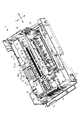
以下、添付した図面を参照して、本発明の一実施形態に係るインクジェット記録装置1について説明する。図1は、インクジェット記録装置1を示した斜視図であり、図2は、装置ハウジング26を省略したインクジェット記録装置1を示した斜視図である。図1および図2に示すように、インクジェット記録装置1は、いわゆるインクジェットプリンターであり、装置本体2と、装置本体2の側面に着脱自在に連結されると共に、各色のインクタンク11を搭載したタンクユニット3と、を備えている。なお、以下、図1および図2においての前後方向をX軸方向とし、左右方向をY軸方向として説明する。
Hereinafter, an inkjet recording apparatus 1 according to an embodiment of the present invention will be described with reference to the accompanying drawings. FIG. 1 is a perspective view showing the ink jet recording apparatus 1, and FIG. 2 is a perspective view showing the ink jet recording apparatus 1 with the
タンクユニット3は、6色のインクをそれぞれ貯留するキャリッジ独立型の6個のインクタンク11と、6個のインクタンク11を覆うタンクハウジング12と、各インクタンク11を上流端に接続したインク供給用のチューブである6本のタンク側インクチューブ13(図2参照)と、を有している。すなわち、6個のインクタンク11および6本のタンク側インクチューブ13により、タンクユニット3側のインク供給系であるタンク側インク供給部を構成している。
The
各タンク側インクチューブ13は、装置本体2の側面に開口したチューブ用開口部14から装置本体2内に引き回され、下流端が後述の中間継手71に接続されている。これによって、タンクユニット3と装置本体2とが流路接続される。また、タンクハウジング12には、タンクユニット3を装置本体2に着脱するための前後一対の係合部15が形成されている。これを装置本体2側の前後一対の被係合部27に係合することによって、タンク側インクチューブ13を接続したまま、タンクユニット3を、装置本体2に対し着脱自在に連結する。なお、タンクユニット3は、インク供給時には縦置き姿勢で装置本体2に装着されており、インクタンク11へのインク補充時には装置本体2から離脱させ横置き姿勢にする。
Each tank-
次に図2ないし図11を参照して、装置本体2について説明する。図2に示すように、装置本体2は、枚葉の記録媒体(印刷用紙や単票紙)を送り経路Rに沿って搬送する搬送部21と、送り経路Rの上方に配設され、記録媒体にインクジェット方式で印刷処理を行う印刷部22と、タンクユニット3(各インクタンク11)からのインクを印刷部22に供給する本体側インク供給部23と、搬送部21および印刷部22の駆動を制御する回路基板61を有した制御部24と、各部を搭載した装置フレーム25と、これらを覆う装置ハウジング26(図1参照)と、を備えている。図1に示すように、装置ハウジング26の側面には、上記一対の係合部15が係合する前後一対の被係合部27が形成されている。また、装置本体2の後面下部には、USBポート16(図5参照)および電源ポートが配設されている。すなわち、インクジェット記録装置1は、USBポート16を介してコンピューター等に接続可能に構成されている。
Next, the apparatus
図3は、装置本体2の断面図である。図2および図3に示すように、搬送部21は、記録媒体を右揃えでセットする給紙トレイ31と、給紙トレイ31から記録媒体を1枚ずつ分離して送り出す分離ローラー32と、分離ローラー32の下流側に配設され、記録媒体を印刷部22直下に送り込む給紙ローラー33と、給紙ローラー33の下流側に配設され、印刷部22(インクジェットヘッド52)に対面する媒体規制部材(プラテンに相当する)34と、媒体規制部材34の下流側に位置する鋸歯状のガイドローラー35と、ガイドローラー35の下流側に位置し、記録媒体を排紙する排紙ローラー36と、排紙された記録媒体を受ける排紙トレイ37と、を備えている。なお、図1に示すように、給紙トレイ31および排紙トレイ37は、収納可能な可動式になっている。
FIG. 3 is a cross-sectional view of the apparatus
給紙ローラー33は、下側の給紙駆動ローラー33aと上側の給紙従動ローラー33bとから成るニップローラーで構成され、同様に排紙ローラー36は、下側の排紙駆動ローラー36aと上側の排紙従動ローラー36bとから成るニップローラーで構成されている。また、ガイドローラー35および排紙従動ローラー36bは、装置フレーム25とは独立のローラーフレーム38に支持されて、ローラーアッセンブリー39を構成している。そして、給紙ローラー33は、記録媒体の送り(副走査)を制御するメインローラーとして機能し、排紙ローラー36は、媒体規制部材34の上側に位置する記録媒体に張力(tension)を付与するテンションローラーとして機能する。
The
図4は、装置本体2の左端部を示した図である。図4に示すように、給紙駆動ローラー33aおよび排紙駆動ローラー36aの左側には、搬送モーター(図示省略)と、搬送モーターの駆動を両ローラー33a、36aに伝達するギア列40と、が配設されている。すなわち、当該搬送モーターおよびギア列40によって、装置本体2の左側部が占領されている。
FIG. 4 is a view showing the left end portion of the apparatus
分離ローラー32により、給紙トレイ31から送り込まれた記録媒体は、給紙ローラー33により、媒体規制部材34上を排紙ローラー36に向かってX軸方向に間欠送りされる(副走査)。この間欠送りに同期して、印刷部22を駆動することで、所望の印刷が行われる。一方、媒体規制部材34を越えてガイドローラー35に達した記録媒体の先端は、ガイドローラー35により上反り状態を矯正されるようにして、排紙ローラー36に送り込まれる。このようにして、印刷が完了した記録媒体は、排紙ローラー36により、排紙トレイ37に送り出される。
The recording medium fed from the
図2に示すように、印刷部22は、装置フレーム25に支持されると共にY軸方向に幅一杯に延在するガイド軸49およびガイドフレーム41と、ガイド軸49およびガイドフレーム41に往復動自在に支持されたキャリッジユニット42と、キャリッジユニット42をガイド軸49およびガイドフレーム41に沿って往復動させるキャリッジ移動機構43と、を備えている。そして、このキャリッジユニット42に、インクジェットヘッド52が搭載されている。
As shown in FIG. 2, the
キャリッジ移動機構43は、ガイドフレーム41に沿って延在するタイミングベルト46と、タイミングベルト46を架け渡した主動プーリ(図示省略)および従動プーリ47と、タイミングベルト46とキャリッジユニット42(キャリッジ51)とを連結する連結固定部(図示省略)と、主動プーリを駆動するキャリッジモーター48と、を備えている。キャリッジモーター48が正逆回転すると、タイミングベルト46を介してキャリッジユニット42がY軸方向(左右方向)に往復動する。この往復動に伴って、キャリッジユニット42のインクジェットヘッド52が吐出駆動することにより、いわゆる主走査が行われる。
The carriage moving mechanism 43 includes a timing belt 46 extending along the
図3に示すように、キャリッジユニット42は、ガイド軸49およびガイドフレーム41に往復動自在に支持された箱状のキャリッジ51と、キャリッジ51の下面に一体に組み込まれたインクジェットヘッド52と、インクジェットヘッド52に上側から接続されると共に、後述の本体側インクチューブ72の下流端が接続された色別の接続アダプター53と、を備えている。インクジェットヘッド52は、6色のインク滴を吐出する6連のノズル列(図示省略)を有していると共に、信号伝達用のフレキシブルフラットケーブル(以下、ヘッド接続用FFC)62を介して回路基板61に接続されている。詳細は後述するが、本体側インクチューブ72は、キャリッジ51の往復動に対し、左側に折返し部分を有して追従変形し、ヘッド接続用FFC62は、キャリッジ51の往復動に対し、右側に折返し部分を有して追従変形する。また、各接続アダプター53は、インクバッファやインクフィルター等を内蔵し、その上部には、本体側インクチューブ72を接続するための流入継手を有している。
As shown in FIG. 3, the
印刷処理では、搬送部21によって記録媒体をX軸方向に間欠送り(副走査)すると共に、インクジェットヘッド52を駆動しつつ、キャリッジ移動機構43によって、キャリッジユニット42をY軸方向に往復させて(主走査)、印刷用紙に画像データを印刷する。なお、インク吐出によるポンプ作用によって、各色のインクが各インクタンク11からインクジェットヘッド52に順次供給される。
In the printing process, the recording unit is intermittently fed (sub-scanned) in the X-axis direction by the
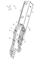
図2に示すように、制御部24は、左側の後端部に配設された回路基板61と、上記のヘッド接続用FFC62を含む各種ケーブルと、ヘッド接続用FFC62をガイドするケーブルフレーム63と、を備えている。ヘッド接続用FFC62は、回路基板61に一端が接続されると共に、直立姿勢で回路基板61から装置本体2の左側面および前面に沿って引き回された後、左右方向に折り返して、他端がキャリッジ51上のインクジェットヘッド52に接続されている。一方、ケーブルフレーム63は、装置本体2の左側面に沿って延在し、左側面に沿ってヘッド接続用FFC62を支持する第1支持フレーム66と、装置本体2の前面に沿って延在し、前面に沿ってヘッド接続用FFC62を支持する第2支持フレーム67と、を有している。よって、ヘッド接続用FFC62は、可動側端部がインクジェットヘッド52に固定されると共に、固定側を第2支持フレーム67に固定され、キャリッジ51の移動に伴って追従変形する。
As shown in FIG. 2, the
ここで図2、図5および図6を参照して、装置本体2側のインク供給系である本体側インク供給部23について説明する。図5は、装置本体2の裏面斜視図である。図2および図5に示すように、本体側インク供給部23は、6本のタンク側インクチューブ13の下流端が接続された中間継手(継手:第2チューブ規制部)71と、上流端が中間継手71に接続され、下流端が接続アダプター53に接続された6本の本体側インクチューブ(インク供給用のチューブ)72と、6本の本体側インクチューブ72をガイドするガイド機構73と、を備えている。
Here, with reference to FIGS. 2, 5, and 6, the main body side
図6は、中間継手71廻り示した斜視図である。図6に示すように、中間継手71は、6本のタンク側インクチューブ13を接続する6個の流入側ポート76と、6本の本体側インクチューブ72を接続する6個の流出側ポート77と、6個の流入側ポート76および6個の流出側ポート77を連結する板状の連結部78と、を備えている。中間継手71によって、タンク側インクチューブ13および本体側インクチューブ72を連結することで、各インクタンク11と接続アダプター53とを接続するインクチューブを構成する。また、中間継手71によって、タンク側インク供給部(各インクタンク11および各タンク側インクチューブ13)と本体側インク供給部23と連結することで、インクジェットヘッド52にインクを供給するインク供給部を構成する。さらに、中間継手71は、下流端を揃えた状態で6本のタンク側インクチューブ13を接続しこの状態で固定(規制)すると共に、上流端を揃えた状態で6本の本体側インクチューブ72を接続しこの状態で固定する。
FIG. 6 is a perspective view around the intermediate joint 71. As shown in FIG. 6, the intermediate joint 71 includes six
図2および図5に示すように、6本の本体側インクチューブ72は、中間継手71と接続アダプター53とを接続するものであり、水平方向に横並びにした状態で、装置本体2内を引き回されている。具体的には、6本の本体側インクチューブ72は、中間継手71から装置本体2の左方向(Y軸方向)に略水平に引き回された後、折り返すように上方に湾曲した折返し部分(以下、折返しチューブ部72a)を有し、さらに奥側に湾曲して接続アダプター53に到達している。よって、平面視において搬送部21にオーバーラップするオーバーラップ位置と、平面視において搬送部21上から外れた非オーバーラップ位置と、に亘って配管されている。加えて、6本の本体側インクチューブ72の下流端部は、キャリッジ51上に固定されており、インクジェットヘッド52側を可動側とし、中間継手71側を固定側として、キャリッジ51の往復動に伴って追従変形するように構成されている。すなわち、本体側インクチューブ72とヘッド接続用FFC62とは、左右方向で逆向きに配設されている。
As shown in FIGS. 2 and 5, the six main body
また、6本の本体側インクチューブ72には、延在方向の複数箇所に、6本の本体側インクチューブ72を横並びに連結する連結体79が設けられ、6本の本体側インクチューブ72は、この複数の連結体79により、相互に束ねるように連結されている。
In addition, the six main body
ガイド機構73は、中間継手71および中間継手71廻りのインクチューブを支持する支持部である継手支持部材81と、キャリッジ51の移動軌跡の前方において、本体側インクチューブ72をガイドするチューブガイド82と、キャリッジ51に搭載され、本体側インクチューブ72の下流端部を固定するキャリッジ固定部材83と、本体側インクチューブ72の折返しチューブ部72aに添設した可撓性の保護プレート84と、を有している。継手支持部材81およびチューブガイド82(後述のガイド固定部113)によって、6本の本体側インクチューブ72の非可動部が配管される固定配管経路を構成し、チューブガイド82(後述の受け板部111および隔板部112)、キャリッジ固定部材83および保護プレート84によって、6本の本体側インクチューブ72の非可動部に上流側に連なる可動部が整列状態で配管される可動配管経路を構成している。なお、固定配管経路の上流端は、中間継手71が配設されている。
The
キャリッジ固定部材83は、本体側インクチューブ72の下流端部をキャリッジ51上に固定すると共に、本体側インクチューブ72を奥側にガイドして、接続アダプター53に導く。
The
保護プレート84は、一端をチューブガイド82に固定され、他端をキャリッジ51上に保持されており、キャリッジ51の往復動に伴って、6本の本体側インクチューブ72と一緒に追従変形する。また、保護プレート84は、6本の本体側インクチューブ72の折返しチューブ部72aに外側から沿設し、折返しチューブ部72aが、その左側や上側の他の構成部材(例えば、装置ハウジング26の側壁や天壁)に接触することを防止している。すなわち、保護プレート84は、チューブ担持体の機能を有している。また、保護プレート84には、6本の本体側インクチューブ72を抱え込むように保持する一対の保持片84a(図中では、開いた状態で図示)が形成されており、追従変形に伴う6本の本体側インクチューブ72の暴れを抑制している。
One end of the
図7は、チューブガイド82を示した図である。図7に示すように、チューブガイド82は、Y軸方向に延在すると共に、本体側インクチューブ72の固定側を支持するチューブ支持部110と、折返しチューブ部72aの変形軌跡の側面に面してチューブ支持部110から立設すると共に、当該折返しチューブ部72aを他の部材から保護する隔板部112と、を備えている。また、チューブ支持部110は、本体側インクチューブ72の折返しチューブ部72aの底辺を受ける受け板部111と、受け板部111に連なると共に本体側インクチューブ72の非可動部を固定するガイド固定部113と、を備えている。なお、受け板部111、隔板部112およびガイド固定部113は、一体に形成されている。
FIG. 7 is a view showing the
ガイド固定部113は、固定配管経路の一部を構成し、ガイド固定部113には、横並びの6本の本体側インクチューブ72が底面に添わせて配管されている。加えて、ガイド固定部113は、固定配管経路に面して配設され、6本の本体側インクチューブ72を不動に固定(規制)する上流側チューブ固定部(第1チューブ規制部)121、下流側チューブ固定部122および中間チューブ固定部123を有している。すなわち、固定配管経路上において、上流側から、上流側チューブ固定部121、中間チューブ固定部123、下流側チューブ固定部122の順で3箇所において、6本の本体側インクチューブ72を固定している。
The
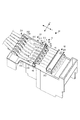
次に図6および図8を参照して、継手支持部材81について説明する。図8(a)は、継手支持部材81を示した斜視図である。図8(b)は、継手支持部材81を示した断面図である。図6および図8に示すように、継手支持部材81は、中間継手71を支持する継手支持部91と、継手支持部91に一体に連なり、6本のタンク側インクチューブ13の下流端部を固定し支持するタンク側チューブ支持部92と、継手支持部91の逆側に連なり、6本の本体側インクチューブ72の上流端部を支持する本体側チューブ支持部93と、を有している。継手支持部91は、一対のコ字状ガイド94、94を有しており、中間継手71を上側からスナップインで装着する。なお、継手支持部材81は、上記の非オーバーラップ位置に配設されている。
Next, the
タンク側チューブ支持部92は、6本のタンク側インクチューブ13を押圧固定するタンク側チューブ固定部材201と、タンク側チューブ固定部材201の幅方向両端をねじ止めするための取付部202と、を有している。すなわち、6本のタンク側インクチューブ13を配管した状態で、取付部202にタンク側チューブ固定部材201をねじ止めすることで、6本のタンク側インクチューブ13を不動に固定する。
The tank-side
本体側チューブ支持部93は、固定配管経路に面して配設されており、本体側チューブ支持部93には、6本の本体側インクチューブ72が水平方向に並べて配管されている。加えて、本体側チューブ支持部93は、6本の本体側インクチューブ72を個々に下方に湾曲させるための空間Sを形成する空間形成部211(すなわち、チューブの一部を収容する収容部)と、6本の本体側インクチューブ72を空間Sにガイドする前後一対の上流側ガイド部212および下流側ガイド部213と、下流側ガイド部213廻りに配設され、湾曲による6本の本体側インクチューブ72の浮き上がりを阻止する浮上がり阻止部214と、を有している。
The main body side
空間形成部211は、6本の本体側インクチューブ72を個々に下方(すなわち、固定配管経路と直交する方向)に湾曲させるための空間Sを存した箱型に形成されており、前後左右の4面の壁体215を有している。詳細は後述するが、空間Sにおいて6本の本体側インクチューブ72を個々に湾曲させることにより、6本の本体側インクチューブ72の長さ誤差を受容する。
The
上流側ガイド部212は、R状のガイド面216を有して、本体側インクチューブ72を空間Sへ先下がりとなるようにガイドする。一方、下流側ガイド部213は、6本の本体側インクチューブ72を高さ違い前後2箇所で支持し、本体側インクチューブ72を空間Sから先上がりになるようにガイドするガイド面217を構成している。当該一対のガイド面216、217によって、本体側インクチューブ72が空間Sに導くと共に、空間S内で「U」字状に湾曲されるようにガイドする。
The upstream
浮上がり阻止部214は、下流側ガイド部213廻りに立設し、6本の本体側インクチューブ72を個々に幅規制する複数の規制片221と、複数の規制片221に側方に突設し、浮き上がりを阻止する複数の阻止突起222と、を一体に有している。複数の規制片221は、6本の本体側インクチューブ72の両端と、本体側インクチューブ72間とにそれぞれ立設し、一方、複数の阻止突起222は、最端の1個の規制片221を除く各規制片221から、側方に且つ本体側インクチューブ72の上面に面して突設している。なお、各阻止突起222は、本体側インクチューブ72を幅方向に潰した状態で上側から複数の規制片221の間に入りこませることが可能で且つ自由状態では上側に抜けることが無い程度の長さに形成されている。
The lifting
ここで図9を参照して、空間Sによる本体側インクチューブ72の長さ誤差の受容方法について説明する。6本の本体側インクチューブ72の長さは、製造誤差や引き回しの差異によって、相互に差(以下、単に長さ誤差と呼称)が生じてしまう。6本の本体側インクチューブ72に長さ誤差があると、折返しチューブ部72aが不揃いの状態となってしまい、その結果、追従変形の際、6本の本体側インクチューブ72が暴れ、他の部材に接触する虞がある。特に、押出し成形を用いて本体側インクチューブ72を成形した場合、本体側インクチューブ72の長さ誤差が大きく、当該問題が生じやすい。これに対し、本実施形態においては、6本の本体側インクチューブ72に長さの誤差が生じた際、中間継手71と上流側チューブ固定部121とにより前後で固定された領域の本体側インクチューブ72を、空間Sにおいて、その誤差分に対応して下方に且つ「U」字状に湾曲させて配管する。
Here, with reference to FIG. 9, a method of accepting the length error of the main body
図9は、本体側インクチューブ72に長さ誤差が生じた際の本体側チューブ支持部93を示した断面図である。ここでは、図9中の最も手前側の本体側インクチューブ231が、想定される誤差範囲の最小値の長さを有し、その奥側の本体側インクチューブ232が、上記誤差範囲の中央値の長さを有し、さらに奥側の本体側インクチューブ233が、上記誤差範囲の最大値の長さを有する場合を例示する。図11に示すように、最小値の本体側インクチューブ231は、空間S上において略直線状に配管する。一方、中央値の本体側インクチューブ232および最大値の本体側インクチューブ233は、最小値の本体側インクチューブ231より長く形成されているので、その長さの差分だけ、空間S上で下方に湾曲させて配管する。この場合、最小値からの差分だけ湾曲しているため、最大値の本体側インクチューブ233は、中央値の本体側インクチューブ232より大きく湾曲させて配管される。
FIG. 9 is a cross-sectional view showing the main body side
このように、中間継手71と上流側チューブ固定部121とにより前後で固定された領域の本体側インクチューブ72を、空間S上において、想定される誤差範囲の最小値に対する差分だけ湾曲させることで、上流側チューブ固定部121から下流側の本体側インクチューブ72の長さを6本の本体側インクチューブ72の相互間で一致させることができる。なお、空間Sは、6本の本体側インクチューブ72において、想定される誤差範囲の誤差分が受容可能な広さ(側方視の面積:長さおよび/または高さ)を有していることが好ましい。
In this way, by bending the main body
以上のような構成によれば、固定配管経路上の空間Sにおいて、各本体側インクチューブ72を、その長さ誤差分に対応して湾曲させることができるため、非可動部で6本の本体側インクチューブ72の長さ誤差を受容することができる。よって、長さ誤差の誤差分が、可動部に誤差蓄積されることがなく、本体側インクチューブ72の追従変形の安定化を図ることができる。また、中間継手71への接続を適切に行うことができる。
According to the configuration as described above, each main body
また、前後一対のガイド面216、217を設けることで、6本の本体側インクチューブ72が空間Sに円滑に導かれるため、本体側インクチューブ72の曲げ曲率を小さくすることができ、圧力損失が小さくインクを安定して供給することができる。また、空間Sでの、6本の本体側インクチューブ72の配管が容易となる。
Further, since the six main body
さらに、浮上がり阻止部214を設けることで、湾曲した際の反力によって、本体側インクチューブ72が浮き上がるのを阻止することができるため、本体側インクチューブ72の直上空間を、他の部材の設置スペースとして有効活用することができる。
Furthermore, by providing the
またさらに、浮上がり阻止部214が、複数の規制片221と、複数の阻止突起222を一体に有することにより、浮上がり阻止部214によって、本体側インクチューブ72の浮上がり阻止と幅規制とを簡単な構成で且つ一体に行うことができる。
Furthermore, the lifting
なお、本実施形態においては、インクタンク11を装置本体2外に配設し、各色のインクチューブを、タンク側インクチューブ13と、本体側インクチューブ72とに分割した構成であったが、インクタンク11を装置本体2内に配設し、色ごとに一体のインクチューブを用いてインクを供給する構成であっても良い。かかる場合、本体側チューブ支持部93において、当該一体のインクチューブ同士の長さ誤差を受容する。
In the present embodiment, the
また、本実施形態においては、下方に湾曲させて長さ誤差を受容する構成であったが、固定配管経路に直交する方向に湾曲する構成であればこれに限るものではない。すなわち、上方に湾曲させて長さ誤差を受容する構成であっても良いし、本体側インクチューブ72によって、湾曲方向を上下で変える(例えば、上下に交互に湾曲させる)構成であっても良い。また、固定配管経路上において、本体側インクチューブ72を鉛直方向に並べて配管した場合には、水平方向のいずれかに湾曲させて長さ誤差を受容する構成とする。
Moreover, in this embodiment, although it was the structure which curves below and receives a length error, if it is the structure curved in the direction orthogonal to a fixed piping path | route, it will not restrict to this. That is, it may be configured to bend upward to receive a length error, or may be configured to change the bending direction up and down (for example, alternately bend up and down) by the main body
ひいては、固定配管経路に直交する方向に湾曲する構成に限らず、本体側インクチューブ72の並び方向に湾曲させる構成であっても良いし、湾曲方向を複数方向とし、本体側インクチューブ72によって、湾曲方向を上下左右で変える構成であっても良い。
Eventually, the configuration is not limited to a configuration that bends in a direction orthogonal to the fixed piping path, and may be a configuration that bends in the direction in which the main body
またさらに、本実施形態においては、想定される誤差範囲の最小値を基準値(最小基準値)とし、当該値からの差分(「0」を含む)だけ、各本体側インクチューブ72を湾曲される構成であったが、6本の本体側インクチューブ72内の最小値を基準値とし、当該値からの差分だけ、最小値の本体側インクチューブ72を除く各本体側インクチューブ72を湾曲される構成であっても良い。
Furthermore, in this embodiment, the minimum value of the assumed error range is set as a reference value (minimum reference value), and each main body
また、本実施形態では、一般的なインクカートリッジの数倍または十数倍の容量を有した大容量のインクタンク11を用いているが、キャリッジ51に対し独立したインクタンク11(所謂オフキャリッジ方式のインクタンク11)であれば、インクカートリッジと同等の容量のインクタンク11を用いるインクジェット記録装置1に、本発明を適用しても良い。
In this embodiment, a large-
1:インクジェット記録装置、 51:キャリッジ、 52:インクジェットヘッド、 71:中間継手、 72:本体側インクチューブ、 93:本体側チューブ支持部、 121:上流側チューブ固定部、 214:浮上がり阻止部、 216、217:ガイド面、 221:規制片、 222:阻止突起、 S:空間 1: ink jet recording apparatus, 51: carriage, 52: ink jet head, 71: intermediate joint, 72: main body side ink tube, 93: main body side tube support part, 121: upstream side tube fixing part, 214: lifting prevention part, 216, 217: guide surface, 221: restricting piece, 222: blocking protrusion, S: space
Claims (7)
前記ヘッドユニットにインクを供給し、前記インクを注入可能なインクタンクと、
一端側が前記インクジェットヘッドに接続される複数本の第1のインク供給用のチューブと、一端側が前記インクタンクに接続される複数本の第2のインク供給用のチューブと、
前記第1のインク供給用のチューブと前記第2のインク供給用のチューブの他端側同士を前記インクを流通可能に接続する接続部材と、
前記複数本の第1のインク供給用のチューブを規制する第1チューブ規制部と、
前記第1チューブ規制部より前記インクタンク側に配設され、前記複数本の第1のインク供給用チューブまたは前記複数本の第2のインク供給用チューブを規制する第2チューブ規制部と、を有し、
前記接続部材と前記第1チューブ規制部の間には、前記複数本の第1のインク供給用のチューブまたは前記複数本の第2のインク供給用のチューブを個々に湾曲させるための空間部を有し、前記複数本の第1のインク供給用のチューブの長さまたは前記複数本の第2のインク供給用のチューブの長さを一致させるために、前記空間部で湾曲させることによって、前記複数本の第1のインク供給用のチューブのそれぞれの長さまたは前記複数本の第2のインク供給用のチューブのそれぞれの長さを調整できることを特徴とするインクジェット記録装置。 An inkjet head mounted on a reciprocating carriage;
An ink tank capable of supplying ink to the head unit and injecting the ink;
And one end of a first ink supply a plurality of that will be connected to the inkjet head tube, and one end of a second ink supply a plurality of which are connected to the ink tank tube,
A connecting member that connects the other end sides of the first ink supply tube and the second ink supply tube so that the ink can flow; and
A first tube restricting portion for restricting the plurality of first ink supply tubes;
A second tube restricting portion that is disposed closer to the ink tank than the first tube restricting portion and restricts the plurality of first ink supply tubes or the plurality of second ink supply tubes. Have
Between the connection member and the first tube restricting portion, there is a space portion for individually bending the plurality of first ink supply tubes or the plurality of second ink supply tubes. The plurality of first ink supply tubes or the plurality of second ink supply tubes in order to match the length of the plurality of first ink supply tubes, An inkjet recording apparatus, wherein the length of each of the plurality of first ink supply tubes or the length of each of the plurality of second ink supply tubes can be adjusted .
前記複数本の第1のインク供給用チューブは、前記搬送部に対してキャリッジ移動方向においてオーバーラップするオーバーラップ位置と、前記搬送部上から外れた非オーバーラップ位置とに亘って配管され、
前記空間部は、前記非オーバーラップ位置に配設されていることを特徴とする請求項1または請求項2に記載のインクジェット記録装置。 A transport unit for transporting the recording medium;
The plurality of first ink supply tubes are piped over an overlap position that overlaps the transport unit in a carriage movement direction and a non-overlap position that deviates from the transport unit,
The ink jet recording apparatus according to claim 1, wherein the space portion is disposed at the non-overlap position.
前記複数の規制片に突設し、浮き上がりを阻止する複数の阻止突起と、を一体に有する
ことを特徴とする請求項6に記載のインクジェット記録装置。 The lifting prevention portion includes a plurality of restricting pieces that individually restrict the width of the plurality of tubes,
7. The ink jet recording apparatus according to claim 6, further comprising a plurality of blocking protrusions that protrude from the plurality of restricting pieces and prevent floating.
Priority Applications (4)
| Application Number | Priority Date | Filing Date | Title |
|---|---|---|---|
| JP2011013757A JP5821196B2 (en) | 2011-01-26 | 2011-01-26 | Inkjet recording device |
| TW101201494U TWM434681U (en) | 2011-01-26 | 2012-01-20 | Ink jet recording apparatus |
| CN 201220027398 CN202656614U (en) | 2011-01-26 | 2012-01-20 | Ink jet recording device |
| RU2012102604/28U RU121923U1 (en) | 2011-01-26 | 2012-01-25 | INJECTED RECORDING DEVICE |
Applications Claiming Priority (1)
| Application Number | Priority Date | Filing Date | Title |
|---|---|---|---|
| JP2011013757A JP5821196B2 (en) | 2011-01-26 | 2011-01-26 | Inkjet recording device |
Publications (3)
| Publication Number | Publication Date |
|---|---|
| JP2012152995A JP2012152995A (en) | 2012-08-16 |
| JP2012152995A5 JP2012152995A5 (en) | 2014-03-06 |
| JP5821196B2 true JP5821196B2 (en) | 2015-11-24 |
Family
ID=46835250
Family Applications (1)
| Application Number | Title | Priority Date | Filing Date |
|---|---|---|---|
| JP2011013757A Active JP5821196B2 (en) | 2011-01-26 | 2011-01-26 | Inkjet recording device |
Country Status (4)
| Country | Link |
|---|---|
| JP (1) | JP5821196B2 (en) |
| CN (1) | CN202656614U (en) |
| RU (1) | RU121923U1 (en) |
| TW (1) | TWM434681U (en) |
Families Citing this family (7)
| Publication number | Priority date | Publication date | Assignee | Title |
|---|---|---|---|---|
| JP6379482B2 (en) | 2013-12-19 | 2018-08-29 | セイコーエプソン株式会社 | Liquid ejector |
| US9315033B2 (en) * | 2014-03-14 | 2016-04-19 | Seiko Epson Corporation | Recording apparatus |
| EP3118001B1 (en) * | 2014-03-14 | 2020-09-02 | Seiko Epson Corporation | Recording apparatus |
| US9573380B2 (en) | 2015-03-23 | 2017-02-21 | Seiko Epson Corporation | Liquid discharging apparatus |
| JP6604021B2 (en) | 2015-04-16 | 2019-11-13 | セイコーエプソン株式会社 | Ink supply system |
| JP2016203991A (en) | 2015-04-16 | 2016-12-08 | セイコーエプソン株式会社 | Liquid container |
| JP6879452B2 (en) * | 2016-11-04 | 2021-06-02 | セイコーエプソン株式会社 | Liquid injection device |
Family Cites Families (8)
| Publication number | Priority date | Publication date | Assignee | Title |
|---|---|---|---|---|
| JP4069606B2 (en) * | 2001-10-16 | 2008-04-02 | セイコーエプソン株式会社 | Ink supply apparatus and inkjet printer |
| JP4068331B2 (en) * | 2001-10-17 | 2008-03-26 | 株式会社ニフコ | Clamp |
| JP3966729B2 (en) * | 2002-01-22 | 2007-08-29 | シャープ株式会社 | Inkjet recording device |
| JP2003326733A (en) * | 2002-05-16 | 2003-11-19 | Sharp Corp | Ink tube support structure and image forming apparatus |
| JP4341434B2 (en) * | 2004-03-12 | 2009-10-07 | セイコーエプソン株式会社 | Ink tube holding mechanism and inkjet printer |
| JP5211687B2 (en) * | 2007-12-28 | 2013-06-12 | ブラザー工業株式会社 | Scanning apparatus and image recording apparatus |
| JP4985500B2 (en) * | 2008-03-21 | 2012-07-25 | セイコーエプソン株式会社 | Liquid supply system and manufacturing method therefor |
| JP4973764B2 (en) * | 2010-06-18 | 2012-07-11 | セイコーエプソン株式会社 | Liquid supply device |
-
2011
- 2011-01-26 JP JP2011013757A patent/JP5821196B2/en active Active
-
2012
- 2012-01-20 CN CN 201220027398 patent/CN202656614U/en not_active Expired - Fee Related
- 2012-01-20 TW TW101201494U patent/TWM434681U/en not_active IP Right Cessation
- 2012-01-25 RU RU2012102604/28U patent/RU121923U1/en not_active IP Right Cessation
Also Published As
| Publication number | Publication date |
|---|---|
| RU121923U1 (en) | 2012-11-10 |
| TWM434681U (en) | 2012-08-01 |
| JP2012152995A (en) | 2012-08-16 |
| CN202656614U (en) | 2013-01-09 |
Similar Documents
| Publication | Publication Date | Title |
|---|---|---|
| JP5821196B2 (en) | Inkjet recording device | |
| JP6021294B2 (en) | Inkjet recording device | |
| JP6183430B2 (en) | Inkjet recording device | |
| JP5691300B2 (en) | Inkjet recording device | |
| JP5958590B2 (en) | Inkjet recording device | |
| JP6021297B2 (en) | Inkjet recording device | |
| JP2006305940A (en) | Device of guiding fluid passage forming body | |
| JP2012148510A (en) | Liquid ejection device | |
| JP5764939B2 (en) | Tube guide and inkjet recording apparatus | |
| JP2012148511A (en) | Liquid injection system | |
| JP5810536B2 (en) | Inkjet recording device | |
| JP2012152995A5 (en) | ||
| WO2013128923A1 (en) | Inkjet recording device | |
| JP5743002B2 (en) | Inkjet recording device | |
| JP2009126144A (en) | Image forming device | |
| JP6424931B2 (en) | Recording device | |
| JP6179550B2 (en) | Inkjet recording device | |
| JP2012061620A (en) | Tube maintaining body and ink jet recording device | |
| JP2011068145A (en) | Liquid jetting apparatus | |
| JP6182828B2 (en) | Liquid ejector | |
| JP6696556B2 (en) | Image forming device | |
| JP5842604B2 (en) | Ink supply apparatus and image recording apparatus | |
| JP2017087659A (en) | Recording device | |
| JP6439721B2 (en) | Liquid ejector | |
| JP2016221867A (en) | Image forming apparatus |
Legal Events
| Date | Code | Title | Description |
|---|---|---|---|
| A521 | Written amendment |
Free format text: JAPANESE INTERMEDIATE CODE: A523 Effective date: 20140116 |
|
| A621 | Written request for application examination |
Free format text: JAPANESE INTERMEDIATE CODE: A621 Effective date: 20140116 |
|
| A977 | Report on retrieval |
Free format text: JAPANESE INTERMEDIATE CODE: A971007 Effective date: 20140808 |
|
| A131 | Notification of reasons for refusal |
Free format text: JAPANESE INTERMEDIATE CODE: A131 Effective date: 20140826 |
|
| A521 | Written amendment |
Free format text: JAPANESE INTERMEDIATE CODE: A523 Effective date: 20141015 |
|
| RD04 | Notification of resignation of power of attorney |
Free format text: JAPANESE INTERMEDIATE CODE: A7424 Effective date: 20150106 |
|
| A131 | Notification of reasons for refusal |
Free format text: JAPANESE INTERMEDIATE CODE: A131 Effective date: 20150407 |
|
| A521 | Written amendment |
Free format text: JAPANESE INTERMEDIATE CODE: A523 Effective date: 20150528 |
|
| TRDD | Decision of grant or rejection written | ||
| A01 | Written decision to grant a patent or to grant a registration (utility model) |
Free format text: JAPANESE INTERMEDIATE CODE: A01 Effective date: 20150908 |
|
| A61 | First payment of annual fees (during grant procedure) |
Free format text: JAPANESE INTERMEDIATE CODE: A61 Effective date: 20150921 |
|
| R150 | Certificate of patent or registration of utility model |
Ref document number: 5821196 Country of ref document: JP Free format text: JAPANESE INTERMEDIATE CODE: R150 |
|
| S531 | Written request for registration of change of domicile |
Free format text: JAPANESE INTERMEDIATE CODE: R313531 |
|
| R350 | Written notification of registration of transfer |
Free format text: JAPANESE INTERMEDIATE CODE: R350 |