JP5818586B2 - Image processing apparatus and image processing method - Google Patents
Image processing apparatus and image processing method Download PDFInfo
- Publication number
- JP5818586B2 JP5818586B2 JP2011189326A JP2011189326A JP5818586B2 JP 5818586 B2 JP5818586 B2 JP 5818586B2 JP 2011189326 A JP2011189326 A JP 2011189326A JP 2011189326 A JP2011189326 A JP 2011189326A JP 5818586 B2 JP5818586 B2 JP 5818586B2
- Authority
- JP
- Japan
- Prior art keywords
- image
- pixel
- component
- image restoration
- color component
- Prior art date
- Legal status (The legal status is an assumption and is not a legal conclusion. Google has not performed a legal analysis and makes no representation as to the accuracy of the status listed.)
- Active
Links
- 238000012545 processing Methods 0.000 title claims description 183
- 238000003672 processing method Methods 0.000 title claims description 8
- 238000000034 method Methods 0.000 claims description 116
- 238000003384 imaging method Methods 0.000 claims description 113
- 230000004075 alteration Effects 0.000 claims description 103
- 230000003287 optical effect Effects 0.000 claims description 102
- 230000008569 process Effects 0.000 claims description 76
- 238000012937 correction Methods 0.000 claims description 48
- 238000012546 transfer Methods 0.000 claims description 37
- 230000008859 change Effects 0.000 claims description 14
- 230000006866 deterioration Effects 0.000 claims description 6
- 230000015556 catabolic process Effects 0.000 claims description 5
- 238000006731 degradation reaction Methods 0.000 claims description 5
- 230000006870 function Effects 0.000 description 66
- 238000011084 recovery Methods 0.000 description 62
- 238000004040 coloring Methods 0.000 description 37
- 230000014509 gene expression Effects 0.000 description 16
- 238000010586 diagram Methods 0.000 description 15
- 230000003044 adaptive effect Effects 0.000 description 14
- 230000000694 effects Effects 0.000 description 11
- 238000003860 storage Methods 0.000 description 7
- 230000001629 suppression Effects 0.000 description 6
- 206010010071 Coma Diseases 0.000 description 4
- 238000001514 detection method Methods 0.000 description 3
- 238000009826 distribution Methods 0.000 description 3
- 230000002093 peripheral effect Effects 0.000 description 3
- 230000003595 spectral effect Effects 0.000 description 3
- 238000013519 translation Methods 0.000 description 3
- 239000003086 colorant Substances 0.000 description 2
- 238000004519 manufacturing process Methods 0.000 description 2
- 230000007246 mechanism Effects 0.000 description 2
- 230000010363 phase shift Effects 0.000 description 2
- 230000009467 reduction Effects 0.000 description 2
- 238000001228 spectrum Methods 0.000 description 2
- 238000012935 Averaging Methods 0.000 description 1
- 230000009471 action Effects 0.000 description 1
- 201000009310 astigmatism Diseases 0.000 description 1
- 230000008901 benefit Effects 0.000 description 1
- 230000000740 bleeding effect Effects 0.000 description 1
- 238000013461 design Methods 0.000 description 1
- 238000011161 development Methods 0.000 description 1
- 238000003702 image correction Methods 0.000 description 1
- 230000006872 improvement Effects 0.000 description 1
- 230000002401 inhibitory effect Effects 0.000 description 1
- 230000010354 integration Effects 0.000 description 1
- 230000004048 modification Effects 0.000 description 1
- 238000012986 modification Methods 0.000 description 1
Images


Classifications
-
- H—ELECTRICITY
- H04—ELECTRIC COMMUNICATION TECHNIQUE
- H04N—PICTORIAL COMMUNICATION, e.g. TELEVISION
- H04N23/00—Cameras or camera modules comprising electronic image sensors; Control thereof
- H04N23/80—Camera processing pipelines; Components thereof
- H04N23/84—Camera processing pipelines; Components thereof for processing colour signals
- H04N23/843—Demosaicing, e.g. interpolating colour pixel values
-
- H—ELECTRICITY
- H04—ELECTRIC COMMUNICATION TECHNIQUE
- H04N—PICTORIAL COMMUNICATION, e.g. TELEVISION
- H04N25/00—Circuitry of solid-state image sensors [SSIS]; Control thereof
- H04N25/10—Circuitry of solid-state image sensors [SSIS]; Control thereof for transforming different wavelengths into image signals
- H04N25/11—Arrangement of colour filter arrays [CFA]; Filter mosaics
- H04N25/13—Arrangement of colour filter arrays [CFA]; Filter mosaics characterised by the spectral characteristics of the filter elements
- H04N25/134—Arrangement of colour filter arrays [CFA]; Filter mosaics characterised by the spectral characteristics of the filter elements based on three different wavelength filter elements
-
- H—ELECTRICITY
- H04—ELECTRIC COMMUNICATION TECHNIQUE
- H04N—PICTORIAL COMMUNICATION, e.g. TELEVISION
- H04N25/00—Circuitry of solid-state image sensors [SSIS]; Control thereof
- H04N25/60—Noise processing, e.g. detecting, correcting, reducing or removing noise
- H04N25/61—Noise processing, e.g. detecting, correcting, reducing or removing noise the noise originating only from the lens unit, e.g. flare, shading, vignetting or "cos4"
- H04N25/611—Correction of chromatic aberration
-
- H—ELECTRICITY
- H04—ELECTRIC COMMUNICATION TECHNIQUE
- H04N—PICTORIAL COMMUNICATION, e.g. TELEVISION
- H04N25/00—Circuitry of solid-state image sensors [SSIS]; Control thereof
- H04N25/60—Noise processing, e.g. detecting, correcting, reducing or removing noise
- H04N25/61—Noise processing, e.g. detecting, correcting, reducing or removing noise the noise originating only from the lens unit, e.g. flare, shading, vignetting or "cos4"
- H04N25/615—Noise processing, e.g. detecting, correcting, reducing or removing noise the noise originating only from the lens unit, e.g. flare, shading, vignetting or "cos4" involving a transfer function modelling the optical system, e.g. optical transfer function [OTF], phase transfer function [PhTF] or modulation transfer function [MTF]
- H04N25/6153—Noise processing, e.g. detecting, correcting, reducing or removing noise the noise originating only from the lens unit, e.g. flare, shading, vignetting or "cos4" involving a transfer function modelling the optical system, e.g. optical transfer function [OTF], phase transfer function [PhTF] or modulation transfer function [MTF] for colour signals
-
- H—ELECTRICITY
- H04—ELECTRIC COMMUNICATION TECHNIQUE
- H04N—PICTORIAL COMMUNICATION, e.g. TELEVISION
- H04N2209/00—Details of colour television systems
- H04N2209/04—Picture signal generators
- H04N2209/041—Picture signal generators using solid-state devices
- H04N2209/042—Picture signal generators using solid-state devices having a single pick-up sensor
- H04N2209/045—Picture signal generators using solid-state devices having a single pick-up sensor using mosaic colour filter
- H04N2209/046—Colour interpolation to calculate the missing colour values
Landscapes
- Engineering & Computer Science (AREA)
- Multimedia (AREA)
- Signal Processing (AREA)
- Physics & Mathematics (AREA)
- Spectroscopy & Molecular Physics (AREA)
- Color Television Image Signal Generators (AREA)
- Image Processing (AREA)
- Color Image Communication Systems (AREA)
Description
本発明は、画像処理装置及び画像処理方法に関し、特に画像回復処理を用いた画像補正技術に関する。 The present invention relates to an image processing apparatus and an image processing method, and more particularly to an image correction technique using an image restoration process.
撮像装置で被写体を撮像して得られた画像には、特に撮像光学系の収差の影響による画質劣化が生じている。例えば、画像のぼけは、撮像光学系の球面収差、コマ収差、像面湾曲、非点収差等による画質劣化である。光の波としての性質である回折の影響を無視すれば、被写体の一点から出た光束は収差のない撮像光学系によって撮像面上で同じ大きさの一点(集光点)に結像される。しかしながら実際には、回折の影響に加え、撮像光学系の収差により、集光点から広がりをもって結像される。 In the image obtained by imaging the subject with the imaging device, image quality deterioration is caused particularly by the influence of the aberration of the imaging optical system. For example, image blur is image quality degradation due to spherical aberration, coma aberration, field curvature, astigmatism, and the like of the imaging optical system. Ignoring the effects of diffraction which is wave nature of light, it is imaged light beam emitted from one point of an object by aberration-free imaging optical system to a point of the same size on the imaging surface (condensing point) . However, in practice, in addition to the influence of diffraction, the image is spread from the focal point due to the aberration of the imaging optical system.
撮像光学系の点像分布関数(PSF: Point Spread Function)は、集光点付近の強度分布、すなわち回折および撮像光学系の収差による像のぼけを表すため、ぼけ成分と呼ぶことにする。このぼけ成分は、いわゆるピントがずれていることによるぼけではなく、ピントが合っていても、光の回折や撮像光学系の収差によって生じるぼけを意味する。 The point spread function (PSF) of the imaging optical system is referred to as a blur component because it represents the intensity distribution near the condensing point, that is, the blur of the image due to diffraction and aberration of the imaging optical system. This blur component means not a blur caused by so-called out-of-focus, but a blur caused by diffraction of light or aberration of the imaging optical system even when the subject is in focus.
また、カラー画像での色にじみも、撮像光学系の軸上色収差、色の球面収差、色のコマ収差に起因するものに関しては、光の波長に応じたぼけ方の相違ということができる。また、横方向の色ズレも、光学系の倍率色収差に起因したものに関しては、光の波長に応じた撮像倍率の相違による位置ずれまたは位相ずれということができる。 Further, color blur in a color image can also be said to be a difference in blurring depending on the wavelength of light with respect to those caused by axial chromatic aberration, color spherical aberration, and color coma aberration of the imaging optical system. In addition, the lateral color misregistration can also be referred to as a positional shift or a phase shift due to a difference in imaging magnification according to the wavelength of light.
点像分布関数をフーリエ変換して得られる光学伝達関数(OTF: Optical Transfer Function)は、収差の周波数成分情報であり、複素数で表される。光学伝達関数の絶対値、即ち振幅成分をMTF(Modulation Transfer Function)と呼び、位相成分をPTF(Phase Transfer Function)と呼ぶ。MTF、PTFはそれぞれ収差による画像劣化の振幅成分および位相成分の周波数特性である。ここでは、位相成分PTFを位相角として以下の式で表す。なお、Re(OTF)、Im(OTF)は、それぞれ光学伝達関数の実部、虚部を表す。
PTF=tan-1(Im(OTF)/Re(OTF)) ・・・(式1)
An optical transfer function (OTF) obtained by Fourier transform of the point spread function is frequency component information of aberration and is represented by a complex number. The absolute value of the optical transfer function, that is, the amplitude component is called MTF (Modulation Transfer Function), and the phase component is called PTF (Phase Transfer Function). MTF and PTF are frequency characteristics of an amplitude component and a phase component of image degradation due to aberration, respectively. Here, the phase component PTF is expressed as the phase angle by the following equation. Re (OTF) and Im (OTF) represent the real part and the imaginary part of the optical transfer function, respectively.
PTF = tan −1 (Im (OTF) / Re (OTF)) (Formula 1)
このように、撮像光学系の光学伝達関数が画像の振幅成分と位相成分の両方を劣化させるため、被写体像の各点は、コマ収差がある場合のように、集光点に対して非対称にぼけている。 In this way, since the optical transfer function of the imaging optical system degrades both the amplitude component and the phase component of the image, each point of the subject image is asymmetric with respect to the focal point as in the case where there is coma aberration. I am blurred.
また、倍率色収差は、光の波長ごとの結像倍率の相違により結像位置がずれる現象である。通常撮像素子にはRGBのカラーモザイクフィルタが設けられており、各画素ではRGBのいずれか一つの色成分を取得するように構成されている。従って、Rの波長、Gの波長、及びBの波長間で結像位置がずれることはもとより、取得した各色成分内にも波長ごとの結像位置のずれ、即ち位相ずれによる像の広がりが発生する。よって、厳密には倍率色収差は単なる平行シフトの色ズレではないが、特に説明が無い限り本明細書では色ズレと倍率色収差とを同義として用いる。 Further, lateral chromatic aberration is a phenomenon in which the imaging position is shifted due to the difference in imaging magnification for each wavelength of light. Usually, an RGB color mosaic filter is provided in the image sensor, and each pixel is configured to acquire any one of RGB color components. Therefore, not only does the imaging position shift between the R wavelength, G wavelength, and B wavelength, but also the image position shift for each wavelength within the acquired color components, that is, the spread of the image due to phase shift occurs. To do. Therefore, strictly speaking, the lateral chromatic aberration is not a simple parallel shift color shift, but unless otherwise specified, in this specification, the color shift and the lateral chromatic aberration are used synonymously.
撮像光学系の光学伝達関数の情報を用い、振幅成分(MTF)および位相成分(PTF)の劣化を補正する、画像回復や画像復元と呼ばれる方法が知られている。そのため、以下では、撮像光学系の光学伝達関数の情報を用いて画像の劣化を補正する処理を画像回復処理と呼ぶ。 There is known a method called image restoration or image restoration that corrects deterioration of an amplitude component (MTF) and a phase component (PTF) using information of an optical transfer function of an imaging optical system. Therefore, in the following, processing for correcting image degradation using information on the optical transfer function of the imaging optical system is referred to as image restoration processing.
ここで、画像回復処理の概要を示す。劣化した画像をg(x,y)、元の画像をf(x,y)、撮像光学系の光学伝達関数を逆フーリエ変換したものである点像分布関数をh(x,y)としたとき、以下の式が成り立つ。ただし、演算子”*”はコンボリューションを示し、(x,y)は画像上の座標を示すものとする。
g(x,y)=h(x,y)*f(x,y) ・・・(式2)
Here, an outline of the image restoration processing is shown. The degraded image is g (x, y), the original image is f (x, y), and the point spread function obtained by inverse Fourier transform of the optical transfer function of the imaging optical system is h (x, y). When the following equation holds: Here, the operator “*” indicates convolution, and (x, y) indicates the coordinates on the image.
g (x, y) = h (x, y) * f (x, y) (Expression 2)
また、この式をフーリエ変換して2次元周波数面での表示形式に変換すると、以下の式のように周波数毎の積の形式になる。Hは点像分布関数をフーリエ変換したものであるので光学伝達関数である。(u,v)は2次元周波数面での座標、即ち周波数を示す。
G(u,v)=H(u,v)・F(u,v) ・・・(式3)
Further, when this equation is Fourier transformed to be converted into a display format on a two-dimensional frequency plane, a product format for each frequency is obtained as in the following equation. Since H is a Fourier transform of the point spread function, it is an optical transfer function. (U, v) indicates the coordinates on the two-dimensional frequency plane, that is, the frequency.
G (u, v) = H (u, v) · F (u, v) (Expression 3)
撮像された劣化画像から元の画像を得るためには、以下のように両辺をHで除算すればよい。
G(u,v)/H(u,v)=F(u,v) ・・・(式4)
このF(u,v)を逆フーリエ変換して実面に戻すことで元の画像f(x,y)が回復像として得られる。
In order to obtain the original image from the captured degraded image, both sides may be divided by H as follows.
G (u, v) / H (u, v) = F (u, v) (Formula 4)
The original image f (x, y) is obtained as a restored image by performing inverse Fourier transform on this F (u, v) and returning it to the actual surface.
ここで、上式の1/Hを逆フーリエ変換したものをRとすると、以下の式のように実面での画像に対するコンボリューション処理を行うことで同様に元の画像を得ることができる。
g(x,y)*R(x,y)=f(x,y) ・・・(式5)
Here, if 1 / H of the above equation is inverse Fourier transformed to R, the original image can be obtained similarly by performing convolution processing on the actual image as in the following equation.
g (x, y) * R (x, y) = f (x, y) (Formula 5)
このR(x,y)を画像回復フィルタと呼ぶ。2次元画像に適用する画像回復フィルタは一般に、画像の各画素に対応したタップ(セル)を有する2次元フィルタとなる。また一般に、画像回復フィルタのタップ数(セルの数)が多いほど回復精度が向上するが、実際のタップ数は要求画質、画像処理能力、収差の特性等に応じて設定される。画像回復フィルタは、撮像光学系の収差の特性を反映する光学伝達関数に基づいているため、振幅成分および位相成分の劣化をともに高精度に補正することができる。このような画像回復フィルタは、水平垂直各3タップ程度のエッジ強調フィルタ(ハイパスフィルタ)のような2次元フィルタとは根本的に異なるものである。 This R (x, y) is called an image restoration filter. An image restoration filter applied to a two-dimensional image is generally a two-dimensional filter having taps (cells) corresponding to each pixel of the image. In general, as the number of taps (cells) of the image restoration filter increases, the restoration accuracy improves. However, the actual number of taps is set according to the required image quality, image processing capability, aberration characteristics, and the like. Since the image restoration filter is based on an optical transfer function that reflects the aberration characteristics of the imaging optical system, both the amplitude component and the phase component can be corrected with high accuracy. Such an image restoration filter is fundamentally different from a two-dimensional filter such as an edge enhancement filter (high-pass filter) of about 3 taps each in horizontal and vertical directions.
例えば、特許文献1には、生体内部を観察するための蛍光内視鏡の撮像画像のうち、合焦範囲外となる部分について、使用する蛍光波長に応じた点像分布関数を用いて像のぼけを解消する手法が開示されている。
For example,
なお、実際の画像にはノイズ成分があるため、光学伝達関数の完全な逆数をとって作成した画像回復フィルタを用いると、ノイズ成分が増幅されてしまい、高画質の回復画像を得ることができない。光学伝達関数の完全な逆数をとって作成した画像回復フィルタは、撮像光学系のMTFが全周波数に渡って1となるようにMTFを補正(増加)することで、撮像光学系による振幅劣化を回復する。そのため、画像の振幅成分にノイズの振幅が付加されていると、MTFとともにノイズのパワースペクトルも上昇し、結果的にMTFの回復度合(回復ゲイン)に応じてノイズが増幅されてしまう。 Since an actual image has a noise component, using an image restoration filter created by taking the perfect reciprocal of the optical transfer function will amplify the noise component, making it impossible to obtain a high-quality restored image. . The image restoration filter created by taking the perfect reciprocal of the optical transfer function corrects (increases) the MTF so that the MTF of the imaging optical system becomes 1 over the entire frequency, thereby reducing the amplitude deterioration due to the imaging optical system. Recover. For this reason, if the amplitude of noise is added to the amplitude component of the image, the power spectrum of the noise increases as well as the MTF, and as a result, the noise is amplified according to the recovery degree (recovery gain) of the MTF.
そのため、例えばウィナーフィルタのように、画像信号とノイズ信号の強度比に応じて画像の高周波側の回復率を抑制する画像回復フィルタを用いることで、回復画像におけるノイズを抑制する方法が知られている。画像の色にじみ成分の劣化の補正は、例えば、画像の色成分毎のぼけ量が均一となるようにぼけ成分を補正することで実現できる。なお、撮像光学系のズーム位置や絞り径等の撮像状態に応じて光学伝達関数が変動するため、撮像状態に応じた画像回復フィルタを用いることにより、精度の良い画像回復処理を実現することができる。 Therefore, for example, as window I Na over filter, in accordance with the intensity ratio of the image signal and the noise signal by using a suppressing image restoration filter high frequency side of the recovery rate of the image, a method of suppressing noise in the recovery image intellectual It has been. The correction of the deterioration of the color blur component of the image can be realized, for example, by correcting the blur component so that the blur amount for each color component of the image becomes uniform. In addition, since the optical transfer function varies depending on the imaging state such as the zoom position and the aperture diameter of the imaging optical system, it is possible to realize accurate image restoration processing by using an image restoration filter corresponding to the imaging state. it can.
このように、撮像画像に対して撮像光学系の点像分布関数を用いた画像回復処理を施すことにより、諸収差を補正して画質を向上させる技術が知られている。
しかしながら、実際の撮像では、入力画像の撮像状態と、適用する画像回復フィルタの状態が最適には一致しない場合がある。
As described above, a technique for improving image quality by correcting various aberrations by performing image restoration processing using a point spread function of an imaging optical system on a captured image is known.
However, in actual imaging, the imaging state of the input image may not optimally match the state of the applied image restoration filter.
例えば、立体被写体の撮像画像がその一例である。撮像装置は、オートフォーカス機能やマニュアルフォーカスにより被写体空間の1つの面に焦点を合わせて撮像するため、合焦面に位置する被写体は比較的先鋭に撮像される。しかし、他の被写体(同一被写体の、合焦面から異なる位置にある部分を含む)は合焦面からの距離に応じたぼけ量で撮像される。 For example, a captured image of a three-dimensional subject is an example. Since the imaging device focuses on one surface of the subject space by the autofocus function or manual focus, the subject located on the in-focus plane is captured relatively sharply. However, other subjects (including portions of the same subject at different positions from the focal plane) are imaged with a blur amount corresponding to the distance from the focal plane.
そして、被写体距離に関する情報が、合焦面までの距離のみの場合、この被写体距離と画角に最適な画像回復フィルタを選択若しくは生成して使用することになる。その結果、合焦物体に対しては最適な画像回復フィルタが適用されるため、望ましい回復結果を得ることができるが、非合焦物体については画像回復フィルタが最適でないため、多少の回復効果はあるものの、ぼけを解消することはできない。 When the information regarding the subject distance is only the distance to the in-focus plane, an image restoration filter optimal for the subject distance and the angle of view is selected or generated and used. As a result, the optimal image restoration filter is applied to the in-focus object, so that a desirable restoration result can be obtained.However, since the image restoration filter is not optimum for the out-of-focus object, some recovery effect is Although there is a blur, it cannot be eliminated.
一方で、写真において被写体のぼけは、被写体の立体感や注視物体を表現するための手法として用いられている。例えば、被写界深度の浅い望遠レンズを用いて主被写体にピントを合わせ、背景を意図的にぼかす写真表現などである。このような写真表現の存在を考慮すれば、合焦被写体はより先鋭化され、非合焦被写体にはぼけが残存する上述の画像回復処理は適切とも考えられる。 On the other hand, blurring of a subject in a photograph is used as a method for expressing the subject's three-dimensional effect or a gaze object. For example, there is a photographic expression in which the background is intentionally blurred by focusing on the main subject using a telephoto lens having a shallow depth of field. Considering the existence of such a photographic expression, the above-described image restoration process in which a focused subject is sharpened and blur remains in an out-of-focus subject is considered appropriate.
しかし、合焦距離の被写体に最適であり、非合焦距離の被写体には最適でない画像回復フィルタを用いて画像回復処理した場合、非合焦距離の被写体に色付きが発生する場合がある。ここでの色付きとは、画像の各色成分のぼけ方の関係が画像回復処理の前後で異なることにより、画像回復処理後の画像の例えば非合焦距離の被写体(非合焦被写体)のエッジ部に、被写体に無い色(偽色)が発生することである。 However, when an image restoration process is performed using an image restoration filter that is optimal for a subject at an in-focus distance and is not optimal for a subject at a non-focus distance, coloring may occur in the subject at the non-focus distance. Colored here means that the relationship between the blurring of each color component of the image is different before and after the image restoration process, so that, for example, an edge portion of a subject at a non-focus distance (non-focused subject) in the image after the image restoration process In addition, a color (false color) that does not exist in the subject occurs.
さらに、このような色付きは立体被写体の撮像に限らず発生する場合がある。本質的には合焦しているか否かに関わらず、画像を撮像した際の収差の状態と、適用する画像回復フィルタが補正する収差の状態とが異なる場合に色付きが発生する。例えば撮像光学系の製造ばらつきや撮像時の光源分光の変動などが原因となりうる。 Furthermore, such coloring may occur not only in the imaging of a three-dimensional object. Inherently, coloring occurs when the state of aberration when an image is captured is different from the state of aberration corrected by the applied image restoration filter, regardless of whether or not the subject is in focus. For example, it may be caused by manufacturing variations of the imaging optical system or fluctuations in the light source spectrum during imaging.
このような色付きを低減する方法として、画像回復処理前の画像の色情報に基づいて、画像回復処理後の画像の色を補正する方法がある。つまり画像の各画素において画像回復処理による色の変化を判定し、画像回復処理による色付きを低減させるという方法である。 As a method of reducing such coloring, there is a method of correcting the color of the image after the image restoration process based on the color information of the image before the image restoration process. That is, it is a method of determining a color change due to the image restoration process at each pixel of the image and reducing coloring due to the image restoration process.
ところで、撮像素子がベイヤー配列のカラーフィルタを備えている場合、撮像素子から得られる画像は各画素がR、G、又はBの1つの色成分を有するRAW画像であるが、このようなRAW画像に対する画像回復処理には2通りの方法が考えられる。1つ目の方法は、RAW画像に対して色補間処理を適用し、各画素がRGB全ての色成分を有する状態にしてから、R,G,Bプレーンの各々に画像回復フィルタを適用する方法である。また、2つ目の方法は、色補間処理を適用せずに、各画素が1つの色成分をもつRAW画像の状態のまま画像回復フィルタを適用する方法である。 By the way, when the image sensor includes a color filter with a Bayer array, an image obtained from the image sensor is a RAW image in which each pixel has one color component of R, G, or B. Such a RAW image There are two possible methods for image restoration processing for the above. The first method is a method in which color interpolation processing is applied to a RAW image so that each pixel has all the RGB color components, and then an image restoration filter is applied to each of the R, G, and B planes. It is. The second method is a method in which an image restoration filter is applied without applying a color interpolation process, with each pixel having a single color component.
各色プレーンに画像回復フィルタを適用する方法は、RAW画像に適用する方法と比較して画像回復処理を適用する画素数と画像回復フィルタのタップ数が多くなるため、画像回復処理の負荷が著しく増大する。そのため、低処理負荷が求められる場合はRAW画像に画像回復処理を適用する方法を用いることになる。しかし、RAW画像に画像回復処理を適用する場合も、画像を撮像した際の収差の状態と、適用する画像回復フィルタが補正する収差の状態とが異なると、RAW画像に色補間処理を含む所謂現像処理を適用して得られる出力画像に色付きが発生することがある。出力画像の画質を向上させるためのRAW画像に対する画像回復処理において生じる色付きは、無視できない画質劣化であり、十分な抑制が必要である。 The method of applying the image restoration filter to each color plane increases the load of the image restoration processing significantly because the number of pixels to which the image restoration processing is applied and the number of taps of the image restoration filter are larger than the method of applying to the RAW image. To do. Therefore, when a low processing load is required, a method of applying image restoration processing to a RAW image is used. However, when image restoration processing is applied to a RAW image, so-called color interpolation processing is included in the RAW image if the state of aberration when the image is captured differs from the state of aberration corrected by the applied image restoration filter. Coloring may occur in an output image obtained by applying development processing. The coloring that occurs in the image restoration process for the RAW image for improving the image quality of the output image is a non-negligible image quality deterioration and needs to be sufficiently suppressed.
しかし、上述のようにRAW画像は各画素が1つの色成分しか持たないため、画像回復処理前後の色の変化を測定するために必要な色情報が存在しない。そのため、画像回復処理前の画像の色情報に基づいて画像回復処理後の画像の色を補正する上述の方法をそのまま適用することはできない。 However, as described above, since each pixel in the RAW image has only one color component, there is no color information necessary for measuring the color change before and after the image restoration process. Therefore, the above-described method for correcting the color of the image after the image restoration process based on the color information of the image before the image restoration process cannot be applied as it is.
特許文献1では、撮像画像の非合焦範囲に対して画像回復処理を行うことで、撮像光学系の浅い被写界深度を補おうとするものである。特許文献1記載の画像回復処理では、非合焦範囲における先鋭度の向上は実現できたとしても、RAW画像に適用した画像回復処理で発生する色付きを十分抑制することはできない。
In
本発明はこのような従来技術の課題に鑑みてなされたものであり、RAW画像に対する画像回復処理において生じる色付きを抑制可能な画像処理装置および画像処理方法を提供することを目的とする。 The present invention has been made in view of the above-described problems of the prior art, and an object thereof is to provide an image processing apparatus and an image processing method capable of suppressing coloring that occurs in an image restoration process for a RAW image.
上述の目的は、撮像装置によって撮像された、各画素が1つの色成分を有する画像における、撮像装置の撮像光学系の収差による画質の劣化を補正するための画像処理装置であって、画像のうち予め定めた基準の色成分について、画素補間処理を行う第1の画素補間手段と、画像のうち基準の色成分以外の色成分の各々について、値を有する画素と画素補間処理後の基準の色成分の対応する画素とから、色差を取得する第1の取得手段と、撮像光学系の収差を示す関数に基づいた画像回復フィルタを、画像の色成分の各々に対して適用する画像回復処理手段と、画像回復フィルタが適用された画像のうち基準の色成分について、画素補間処理を行う第2の画素補間手段と、画像回復フィルタが適用された画像のうち基準の色成分以外の色成分の各々について、値を有する画素と第2の画素補間手段による画素補間処理後の基準の色成分の対応する画素とから、色差を取得する第2の取得手段と、第1の取得手段と第2の取得手段が取得した色差の変化に応じて、画像回復フィルタが適用された画像の画素値を補正する画素値補正手段と、を有し、画素値補正手段による画素値の補正がなされるまでは、画像および画像回復フィルタが適用された画像のいずれについても、基準の色成分以外の色成分についての画素補間処理を行わないことを特徴とする画像処理装置によって達成される。 The above-described object is an image processing apparatus for correcting image quality degradation due to aberration of an imaging optical system of an imaging apparatus in an image captured by the imaging apparatus and each pixel having one color component. Of these, a first pixel interpolation unit that performs pixel interpolation processing for a predetermined reference color component, and a pixel having a value and a reference pixel after pixel interpolation processing for each color component other than the reference color component in the image Image restoration processing for applying, to each of the color components of the image, a first obtaining unit that obtains a color difference from a pixel corresponding to the color component, and an image restoration filter based on a function indicating aberration of the imaging optical system Means, a second pixel interpolation means for performing pixel interpolation processing on a reference color component in an image to which the image restoration filter is applied, and a color component other than the reference color component in an image to which the image restoration filter is applied For each, a second acquisition unit that acquires a color difference from a pixel having a value and a pixel corresponding to a reference color component after pixel interpolation processing by the second pixel interpolation unit, a first acquisition unit, and a second acquisition unit depending on the change in color difference acquisition means has acquired, possess the pixel value correcting means for correcting the pixel value of the image by the image restoration filter has been applied, the up correction of the pixel value by the pixel value correcting unit is made Is achieved by an image processing apparatus that does not perform pixel interpolation processing for color components other than the reference color component for both the image and the image to which the image restoration filter is applied .
このような構成により本発明によれば、RAW画像に対する画像回復処理において生じる色付きを抑制可能な画像処理装置および画像処理方法を提供することができる。 With such a configuration, according to the present invention, it is possible to provide an image processing apparatus and an image processing method capable of suppressing coloring that occurs in an image restoration process for a RAW image.
以下、添付図面を参照して、本発明をその例示的な実施形態に基づいて詳細に説明する。以下に、本発明の好ましい実施の形態を、添付の図面に基づいて詳細に説明する。 Hereinafter, the present invention will be described in detail based on exemplary embodiments with reference to the accompanying drawings. Hereinafter, preferred embodiments of the present invention will be described in detail with reference to the accompanying drawings.
(撮像装置の構成)
図1は、本発明の実施形態にかかる画像処理装置の一例としての撮像装置の構成例を示すブロック図である。本実施形態では撮像光学系および撮像素子を有する撮像装置に本発明を適用した例を説明するが、本発明において撮像光学系や撮像素子といった撮像画像を生成するための構成要素は必須でない。
(Configuration of imaging device)
FIG. 1 is a block diagram illustrating a configuration example of an imaging apparatus as an example of an image processing apparatus according to an embodiment of the present invention. In this embodiment, an example in which the present invention is applied to an imaging apparatus having an imaging optical system and an imaging element will be described. However, in the present invention, components for generating a captured image such as an imaging optical system and an imaging element are not essential.
不図示の被写体の光学像を撮像光学系101で撮像素子102に結像する。撮像素子102で結像光が電気信号に変換され、A/Dコンバータ103でデジタル信号に変換されて、画像処理部104に入力される。画像処理部104は画像回復処理部111と、画像回復処理以外の画像処理を行う、他の画像処理部112から構成される。画像回復処理部111は、まず、状態検知部107から撮像装置の撮像状態の情報を得る。状態検知部107は撮像装置の撮像状態の情報をシステムコントローラ110から直接得ても良いし、例えば撮像光学系101に関する撮像状態の情報は撮像光学系制御部106から得てもよい。
An optical image of a subject (not shown) is formed on the
次に画像回復処理部111は、撮像状態に応じた画像回復フィルタを例えば記憶部108から選択し、画像回復処理部111は画像処理部104に入力された画像に対して倍率色収差補正処理および画像回復フィルタ適用処理を行う。画像回復処理部111の詳細については後述する。記憶部108で保持するデータは画像回復フィルタではなく、画像回復フィルタを生成するために必要な情報(例えば点像分布関数や光学伝達関数に関する情報)でもよい。この場合、画像回復処理部111は撮像状態に応じた点像分布関数又は光学伝達関数に関する情報を記憶部108から選択して撮像状態に応じた画像回復フィルタを生成し、この画像回復フィルタを用いて画像回復処理を行う。また、他の画像処理部112は画像回復処理後の画像に対し、ガンマ補正やカラーバランス調整など、所定の画像処理を行ないJPEG等の画像ファイルを生成する。
Next, the image
画像処理部104で処理された出力画像は、システムコントローラ110が画像記録媒体109に所定のフォーマットで保存する。また、表示部105には、画像回復処理後の画像に表示用の所定の処理を行った画像を表示しても良いし、画像回復処理を行わない、又は簡易的な回復処理を行った画像を表示しても良い。
The output image processed by the
一連の制御はシステムコントローラ110で行われ、撮像光学系101の機械的な駆動(絞り101a、フォーカスレンズ101b、光学ズームの駆動など)はシステムコントローラ110の指示により撮像光学系制御部106で行う。システムコントローラ110は例えばCPUやMPUのようなプログラマブルなコントローラであり、記憶部108に記憶されたプログラムを実行することで撮像装置の全体的な動作を実現する。なお、画像処理部104はハードウェアで実現してもよいが、少なくとも一部をシステムコントローラ110がソフトウェア的に実現することも可能である。
A series of control is performed by the
絞り101aは、Fナンバーの撮像状態設定として開口径が制御される。フォーカスレンズ101bは、被写体距離に応じてピント調整を行うために不図示のオートフォーカス(AF)機構や手動のマニュアルフォーカス機構によりレンズの位置が制御される。撮像光学系101にはローパスフィルタや赤外線カットフィルタ等の光学素子を入れても構わない。ただし、ローパスフィルタ等の光学伝達関数の特性に影響を与える素子を用いる場合には、画像回復フィルタを作成する時点でその光学素子による光学伝達関数の変化を考慮する。赤外カットフィルタにおいても、分光波長の点像分布関数の積分値であるRGBチャンネルの各点像分布関数、特にRチャンネルの点像分布関数に影響するため、画像回復フィルタを作成する時点で赤外カットフィルタによる点像分布関数の変化を考慮する。
また、撮像光学系101は撮像装置の一部として図示しているが、レンズ交換式カメラのような交換可能な構成であっても良い。
The aperture of the diaphragm 101a is controlled as an F number imaging state setting. The
Further, although the imaging
(画像回復処理部111)
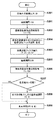
図2は画像回復処理部111の機能構成例を示すブロック図、図3は画像回復処理部111における画像回復処理を説明するためのフローチャートである。
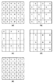
画像回復処理部111には、図4(a)に示すように各画素が1つの色成分を持つRAW画像が入力される。従って、図4(b)〜(d)に示すように、各色成分は一部の画素にのみ値を有する。画像回復処理部111での処理は、図4(b)〜(d)に示す色成分(色プレーン)ごとに行われる。ここでは、RAW画像が色成分ごとに入力されているように図示しているが、実際に色プレーンごとに分離して入力するようにしてもよいし、RAW画像が保存されたメモリから、必要な色成分だけ読み出して処理するように構成してもよい。
(Image recovery processing unit 111)
FIG. 2 is a block diagram illustrating a functional configuration example of the image
As shown in FIG. 4A, the image
図3のS201で第1の画素補間部1001は、G成分(図4(b))に対して画素補間処理を適用し、G成分の値がない画素に対応するG成分の値を求める。この画素補間処理により、図4(e)に示すように各画素がG成分の値を有するようになる。
In S201 of FIG. 3, the first
S202で回復前色差算出部(R)1002は、第1の画素補間部1001が出力する画素補間処理後のG成分(図4(e))と、画素補間していない状態のR成分(図4(c))とから、画像回復処理前の色情報としての色差情報を取得する。また同様に、回復前色差算出部(B)1003が、第1の画素補間部1001が出力する画素補間処理後のG成分(図4(e))と、画素補間していない状態のB成分(図4(d))とから、画像回復処理前の色情報としての色差情報を取得する。色差情報を取得する。回復前色差算出部(R)1002及び回復前色差算出部(B)1003は、第1の取得手段に相当する。
In S202, the pre-recovery color difference calculation unit (R) 1002 outputs a G component after pixel interpolation processing (FIG. 4E) output from the first
本実施形態では、色差を、基準の色成分(ここではG)の信号値との差分と定義する。従って、基準の色成分以外の色成分であるR成分、B成分の、G成分に対する色差C1r、C1bは、以下の式6、式7により計算される。式6,式7において(x,y)は画像上の座標値である。
C1r(x,y)=R(x,y)− G(x,y) ・・・(式6)
C1b(x,y)=B(x,y)− G(x,y) ・・・(式7)
In the present embodiment, the color difference is defined as a difference from the signal value of the reference color component (here, G). Accordingly, the color differences C1r and C1b of the R component and B component, which are color components other than the reference color component, with respect to the G component are calculated by the following equations 6 and 7. In Expressions 6 and 7, (x, y) is a coordinate value on the image.
C1r (x, y) = R (x, y) -G (x, y) (Formula 6)
C1b (x, y) = B (x, y) -G (x, y) (Expression 7)
なお、上述の通りR成分及びB成分は画素補間していないので、S202で色差を計算する画素は、基準の色成分以外の色成分であるR成分、B成分のうち、値が存在する画素のみである。つまり、回復前色差算出部(R)1002は、図4(c)で「R」と記載された画素についてのみC1r(x,y)を計算し、回復前色差算出部(B)1003は図4(d)で「B」と記載された画素についてのみC1b(x,y)を計算する。 Since the R component and the B component are not subjected to pixel interpolation as described above, the pixel for which the color difference is calculated in S202 is a pixel having a value among the R component and the B component that are color components other than the reference color component. Only. That is, the pre-recovery color difference calculation unit (R) 1002 calculates C1r (x, y) only for the pixels described as “R” in FIG. 4C, and the pre-recovery color difference calculation unit (B) 1003 C1b (x, y) is calculated only for the pixels described as “B” in 4 (d).
このように、第1の画素補間部1001で基準色成分(G成分)を画素補間することで、他の色成分(R,B成分)について画素補間せずに、色付き抑制処理に必要な画像回復フィルタ適用前の色差情報を取得することができる。ベイヤー配列のカラーフィルタを備えた撮像素子で得られるRAW画像については、従来から様々な画素補間技術が開示されており、第1の画素補間部1001は既知の任意の方法を用いることができる。例えば、対象画素の特定の色成分の値を、周囲の画素の他の色成分の値を用いて決定した補間方法で求めることができる。つまり、ある画素のG成分の値を補間処理により生成する場合、周囲の画素のR、B成分の値を用いてG成分の補間方法を決定する。近傍の同じ色成分の値を単純に線形補間するような方法と比較して、このような適応的な方法は、補間処理による偽色の発生や先鋭度の低下を低減することが可能である。
In this way, the first
図5を参照して、適応的な画素補間処理方法の一例をさらに説明する。図5(a)は、画像の無彩色のエッジと直交する方向に並んだ画素値の例を示している。このエッジは無彩色であるため、撮像素子の各画素におけるRGB成分の値は等しい。ここでは図5(b)に示すように、(R,G,B)=(100,100,100)の画素と、(R,G,B)=(200,200,200)の画素とから構成されるものとする。実際にはベイヤー配列の撮像素子で撮像されたRAW画像は各画素とも1つの色成分を持つため、色成分ごとに値を抽出すると、図5(c)〜(e)に示す配列となる。図5(c)〜(e)において黒い画素が補間の必要な画素である。この場合、画素補間処理後の各色成分の値が、図5(b)に示した値になることが理想であることは明らかである。 An example of an adaptive pixel interpolation processing method will be further described with reference to FIG. FIG. 5A shows an example of pixel values arranged in a direction orthogonal to the achromatic edge of the image. Since this edge is achromatic, the RGB component values in each pixel of the image sensor are equal. Here, as shown in FIG. 5B, it is assumed that the pixel is composed of (R, G, B) = (100, 100, 100) pixels and (R, G, B) = (200, 200, 200) pixels. Actually, a RAW image captured by an image sensor with a Bayer array has one color component for each pixel. Therefore, when a value is extracted for each color component, an array shown in FIGS. 5C to 5E is obtained. In FIGS. 5C to 5E, black pixels are pixels that require interpolation. In this case, it is obvious that the value of each color component after pixel interpolation processing is ideally the value shown in FIG.
以後、図5(c)〜(e)の画素配列はG(x,y)、R(x,y)、B(x,y)と記述する。ここでxは横方向の座標、yは縦方向の座標であり、図示の通り左上角の画素が(0,0)、右下角の画素が(4,4)の座標値を有する。 Hereinafter, the pixel array in FIGS. 5C to 5E is described as G (x, y), R (x, y), and B (x, y). Here, x is a coordinate in the horizontal direction, and y is a coordinate in the vertical direction. As illustrated, the pixel at the upper left corner has a coordinate value of (0, 0), and the pixel at the lower right corner has a coordinate value of (4, 4).
上述の通り、S201において第1の画素補間部1001はG成分に対して画素補間処理を行なう。図5(c)に示す状態のG成分の黒い画素の値を周囲の他の色成分の画素情報を使って適応的に生成する画素補間処理の例を、以下に説明する。
As described above, in S201, the first
(例えばG(1,2)のように、R成分に値をもつ画素のG成分の値を求める場合)
H_DIFF=(R(x,y)−R(x−2,y))
+(R(x,y)−R(x+2,y)) ・・・(式8)
V_DIFF=(R(x,y)−R(x,y−2))
+(R(x,y)−R(x,y+2)) ・・・(式9)
(For example, when obtaining the value of the G component of a pixel having a value in the R component such as G (1,2))
H_DIFF = (R (x, y) -R (x-2, y))
+ (R (x, y) -R (x + 2, y)) (Formula 8)
V_DIFF = (R (x, y) -R (x, y-2))
+ (R (x, y) -R (x, y + 2)) (Formula 9)
|H_DIFF|>|V_DIFF|の場合、
G(x,y)=(G(x,y−1)+G(x,y+1))/2 ・・・(式10)
|H_DIFF|≦|V_DIFF|の場合、
G(x,y)=(G(x−1,y)+G(x+1,y))/2 ・・・(式11)
| H_DIFF |> | V_DIFF |
G (x, y) = (G (x, y-1) + G (x, y + 1)) / 2 (Expression 10)
| H_DIFF | ≦ | V_DIFF |
G (x, y) = (G (x-1, y) + G (x + 1, y)) / 2 (Expression 11)
このように、対象の画素が有する色成分について、周辺の画素値から計算した水平方向及び垂直方向の画素値の変化量であるH_DIFF、V_DIFFを求め、変化量の絶対値が小さい方向を決定する。そして、対象の画素を挟んで位置する、一対の同色成分の画素値を補間(ここでは平均)して対象の画素における色成分値を求めることができる。このような適応的な画素補間処理の結果を図5(i)に示す。また、式8〜11を用いて説明した適応的な画像補間処理を適用せず、周辺の同色画素の画素値を単純に補間する画素補間処理の結果を図5(f)〜(h)に示す。G画素についての画素補間処理結果である図5(i)及び(f)の比較から明らかなように、適応的な画素補間処理を行った場合は、線形補間を行なった場合に対して先鋭度が低下していないことが分かる。 Thus, the color component included in the pixel of interest, the amount of change in the pixel values of the calculated horizontal and vertical directions from the periphery of the pixel values H_DIFF, seeking V_DIFF, a direction the absolute value of the amount of change is small decide. Then, it is possible to obtain a color component value in the target pixel by interpolating (here, averaging) a pair of pixel values of the same color component located across the target pixel. The result of such adaptive pixel interpolation processing is shown in FIG. Also, without applying adaptive image interpolation processing described with reference to Formula 8-11, the results of the pixel interpolation processing for simply interpolated pixel values of the same color pixels around Figure 5 (f) ~ (h) Show. As is apparent from the comparison of FIGS. 5 (i) and 5 (f), which are the results of the pixel interpolation processing for the G pixel, when the adaptive pixel interpolation processing is performed, the sharpness is higher than when linear interpolation is performed. It can be seen that is not reduced.
R成分の値をもつ画素に対するG成分の値を生成する場合について説明したが、例えばG(2,1)のように、B成分の値をもつ画素に対するG成分の値を生成する場合も同様に行なうことができる。
なお、ここで説明した画素補間方法は単なる例示であって、第1の画素補間部1001が用いる画素補間方法は、単なる線形補間方法を含む他の方法を採用することができる。
Although the case of generating the G component value for the pixel having the R component value has been described, the same applies to the case of generating the G component value for the pixel having the B component value, such as G (2, 1). Can be done.
Note that the pixel interpolation method described here is merely an example, and the pixel interpolation method used by the first
図3に戻り、S203で回復フィルタ適用部(G)1004、回復フィルタ適用部(R)1005、回復フィルタ適用部(B)1006は、撮像条件に適した画像回復フィルタを選択する。このとき、選択された画像回復フィルタを必要に応じて補正しても構わない。これは、予め記憶部108に用意しておく画像回復フィルタのデータ数を低減するために、離散的な撮像状態のデータを用意しておいて、画像回復処理を実行する際に、実際の撮像状態に応じて画像回復フィルタを補正することである。また、画像回復フィルタの選択ではなく、画像回復フィルタを生成するために必要な光学伝達関数に関する情報から、撮像状態に応じた画像回復フィルタを生成してもよい。
Returning to FIG. 3, in S203, the recovery filter application unit (G) 1004, the recovery filter application unit (R) 1005, and the recovery filter application unit (B) 1006 select an image recovery filter suitable for the imaging condition. At this time, the selected image restoration filter may be corrected as necessary. This is because, in order to reduce the number of data of the image restoration filter prepared in advance in the
S204で回復フィルタ適用部(G)1004、回復フィルタ適用部(R)1005及び回復フィルタ適用部(B)1006は、S203で選択もしくは生成した画像回復フィルタを用いて、入力画像の色成分ごとに、各画素に対してコンボリューション処理を行う。コンボリューション処理の詳細は、式5を用いて上述した通りである。これにより、撮像光学系101の収差による点像分布関数の非対称性を補正し、画像のぼけ成分を除去もしくは低減することができる。回復フィルタ適用部(G)1004、回復フィルタ適用部(R)1005及び回復フィルタ適用部(B)1006は、画像回復処理手段に相当する。
In step S204, the restoration filter application unit (G) 1004, the restoration filter application unit (R) 1005, and the restoration filter application unit (B) 1006 use the image restoration filter selected or generated in step S203 for each color component of the input image. The convolution process is performed on each pixel. The details of the convolution process are as described above using
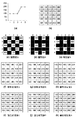
上述の通り、画像回復フィルタは2次元画像に適用する場合、画素に対応するタップを有する2次元フィルタとして構成され、タップ数は撮像光学系の収差特性や要求される回復精度に応じて決定することができる。図6(a)は、例として、水平及び垂直方向に11タップを有する11×11タップの2次元フィルタで構成された画像回復フィルタを模式的に示している。なお、図6(a)に示す画像回復フィルタは、各画素がRGBの各色成分を有する画像の各色プレーンに適用する画像回復フィルタの例である。 As described above, when applied to a two-dimensional image, the image restoration filter is configured as a two-dimensional filter having taps corresponding to pixels, and the number of taps is determined according to the aberration characteristics of the imaging optical system and the required restoration accuracy. be able to. FIG. 6A schematically shows, as an example, an image restoration filter constituted by an 11 × 11 tap two-dimensional filter having 11 taps in the horizontal and vertical directions. Note that the image restoration filter shown in FIG. 6A is an example of an image restoration filter that is applied to each color plane of an image in which each pixel has RGB color components.
図6(a)に示すように画像回復フィルタを100以上のタップを有する2次元フィルタとすることで、撮像光学系による球面収差、コマ収差、軸上色収差、軸外色フレア等の、結像位置から大きく広がる収差に対しても回復することができる。 As shown in FIG. 6A, the image restoration filter is a two-dimensional filter having 100 or more taps, so that imaging of spherical aberration, coma aberration, axial chromatic aberration, off-axis color flare, etc. by the imaging optical system is performed. It is also possible to recover from aberrations that greatly spread from the position.
図6(a)では各タップの値(係数値)の記載を省略しているが、画像回復フィルタの1水平ラインのタップ係数の分布例を図6(b)に示す。画像回復フィルタのタップの値(係数値)の分布が、撮像光学系の収差によって空間的な広がりを持つ点像分布関数を、理想的には元の1点に戻す(回折の影響を無視した場合)役割を果たしている。 In FIG. 6A, the value of each tap (coefficient value) is not shown, but an example of tap coefficient distribution of one horizontal line of the image restoration filter is shown in FIG. The point spread function, whose distribution of the tap values (coefficient values) of the image restoration filter has a spatial spread due to the aberration of the imaging optical system, is ideally restored to the original point (ignoring the effects of diffraction) If) play a role.
画像回復フィルタのタップ係数値は、画像回復処理の工程で実行される画素ごとのコンボリューション処理(畳み込み積分、積和)に用いられる。コンボリューション処理では、処理対象の画素の信号値に画像回復処理を適用するために、処理対象の画素を画像回復フィルタの中心タップと一致させる。そして、画像回復フィルタの各タップ位置において、対応する画素信号値とタップ係数値との積を求め、積の総和で処理対象の画素の信号値を置き換える。 The tap coefficient value of the image restoration filter is used for the convolution process (convolution integration, product sum) for each pixel executed in the image restoration process. In the convolution process, in order to apply the image restoration process to the signal value of the pixel to be processed, the pixel to be processed is matched with the center tap of the image restoration filter. Then, the product of the corresponding pixel signal value and the tap coefficient value is obtained at each tap position of the image restoration filter, and the signal value of the pixel to be processed is replaced with the sum of the products.
このような画像回復フィルタは、上述のように撮像光学系の光学伝達関数を計算若しくは計測し、光学伝達関数の逆関数を逆フーリエ変換して得ることができる。なお、実際の画像にはノイズ成分があるため、光学伝達関数の完全な逆数をとって作成した画像回復フィルタを用いると、ノイズ成分が増幅されてしまい、高画質の回復画像を得ることができない。そのため、例えば後述するウィナーフィルタのように、画像信号とノイズ信号の強度比に応じて画像の高周波側の回復率を抑制する画像回復フィルタを用いることで、回復画像におけるノイズを抑制する方法が知られている。 Such an image restoration filter can be obtained by calculating or measuring the optical transfer function of the imaging optical system as described above and performing inverse Fourier transform on the inverse function of the optical transfer function. Since an actual image has a noise component, using an image restoration filter created by taking the perfect reciprocal of the optical transfer function will amplify the noise component, making it impossible to obtain a high-quality restored image. . Therefore, as the window I Na over filter example described below, the use of the inhibiting image restoration filter frequency side of the recovery rate of the image in accordance with the intensity ratio of the image signal and the noise signal, suppressing noise in the recovery image METHOD It has been known.
さらに、光学伝達関数は撮像光学系のみならず、画像処理部104に入力される画像に対して、光学伝達関数を劣化させる要因を含めることができる。例えば、ローパスフィルタは光学伝達関数の周波数特性おける高周波成分を抑制する。また、撮像素子の画素開口の形状や開口率も周波数特性に影響を与える。光源の分光特性や各種波長フィルタの分光特性もまた光学伝達関数に影響する。従って、これら様々な要因を含めた広義の光学伝達関数に基づいて画像回復フィルタを作成することが望ましい。
Furthermore, the optical transfer function can include not only the imaging optical system but also a factor that degrades the optical transfer function with respect to an image input to the
また、画像がRGB形式のカラー画像である場合は、R、G、Bの各色成分に対応した3つの画像回復フィルタを作成すれば良い。撮像光学系には色収差があり、色成分によってぼけ方が異なるため、画像回復フィルタもまた対象とする色成分に応じて特性が異なる。具体的には、図6(b)に示すタップ値の変化が色成分毎に異なる。画像回復フィルタの縦横のタップ数が等しい必要はなく、コンボリューション処理が可能な範囲で任意に変更することができる。 If the image is an RGB color image, three image restoration filters corresponding to the R, G, and B color components may be created. Since the imaging optical system has chromatic aberration, and the blur is different depending on the color component, the image restoration filter also has different characteristics depending on the target color component. Specifically, the change in tap value shown in FIG. 6B is different for each color component. The number of vertical and horizontal taps of the image restoration filter does not have to be equal, and can be arbitrarily changed within a range where convolution processing is possible.
各画素がRGBの各色成分を有する画像の各色プレーンに適用する画像回復フィルタに対し、本実施形態のように、各画素が1つの色成分のみを有するRAW画像に適用する画像回復フィルタの例を図7に示す。対象の色成分が存在する画素に対応したタップが係数を有し、図7(a)はG成分に提供する画像回復フィルタを、図7(b)はR、B成分に適用する画像回復フィルタを模式的に示している。図7(a),(b)において、黒いタップがタップ係数を有し(タップ係数が0でない)、白いタップはタップ係数を有していない(タップ係数が0)。 An example of an image restoration filter that is applied to a RAW image in which each pixel has only one color component as in this embodiment, as opposed to an image restoration filter that is applied to each color plane of an image in which each pixel has RGB color components. As shown in FIG. The tap corresponding to the pixel in which the target color component exists has a coefficient. FIG. 7A shows an image restoration filter provided to the G component, and FIG. 7B shows an image restoration filter applied to the R and B components. Is schematically shown. 7A and 7B, a black tap has a tap coefficient (a tap coefficient is not 0), and a white tap has no tap coefficient (a tap coefficient is 0).
回復フィルタ適用部(G)1004は、図4(b)に示す(画素補間されていない)G成分に対し、図7(a)に示す画像回復フィルタを用いたコンボリューション処理を適用する。また、回復フィルタ適用部(R)1005と回復フィルタ適用部(B)1006は、図4(c)及び(d)に示したR成分及びB成分に対し、図7(b)に示す画像回復フィルタを用いたコンボリューション処理をそれぞれ適用する。 The recovery filter application unit (G) 1004 applies the convolution process using the image recovery filter shown in FIG. 7A to the G component shown in FIG. 4B (not subjected to pixel interpolation). Further, the recovery filter application unit (R) 1005 and the recovery filter application unit (B) 1006 perform image recovery shown in FIG. 7B with respect to the R component and B component shown in FIGS. 4C and 4D. Each convolution process using a filter is applied.
図3のS205では、画像回復フィルタが適用されたG成分に対し、第2の画素補間部1007で画素補間処理を適用する。これは第1の画素補間部1001がS201で行うものと同様の処理であり、この画素補間処理によりG成分が図4(b)に示した状態から図4(e)に示す各画素がG成分の値を有する状態になる。
In S205 of FIG. 3, the second
S206では、第2の取得手段に相当する回復後色差算出部(R)1008と回復後色差算出部(B)1009で色差情報を取得する。ここでの色差計算はS202で回復後色差算出部(R)1002と回復後色差算出部(B)1003が行なうものと同様であり、基準色成分であるG成分に対するR成分、B成分の差として以下の式によって求める。すなわち、R成分、B成分のG成分に対する色差C2r、C2bは、次式で定義される。
C2r(x,y)=R(x,y)− G(x,y) ・・・(式12)
C2b(x,y)=B(x,y)− G(x,y) ・・・(式13)
このように、第2の画素補間部1007でG成分にのみ画素補間を行なうことで、色付き抑制処理に必要な画像回復フィルタ適用後の色差情報を取得することができる。
In S206, color difference information is acquired by a post-recovery color difference calculation unit (R) 1008 and a post-recovery color difference calculation unit (B) 1009 corresponding to the second acquisition unit. The color difference calculation here is the same as that performed by the post-recovery color difference calculation unit (R) 1002 and the post-recovery color difference calculation unit (B) 1003 in S202, and the difference between the R component and the B component with respect to the G component as the reference color component. As follows. That is, the color differences C2r and C2b of the R component and the B component with respect to the G component are defined by the following equations.
C2r (x, y) = R (x, y) −G (x, y) (Equation 12)
C2b (x, y) = B (x, y) -G (x, y) (Equation 13)
In this way, by performing pixel interpolation only on the G component in the second
S207で画素値調整部(R)1010は色差情報C1rとC2rとから、画素値調整部(B)1011はCb1とC2bとから、それぞれR成分及びB成分について色付き抑制のための画素値調整が必要か否かを決定する。画素値調整部(R)1010及び画素値調整部(B)1011は、画素値補正手段に相当する。この決定は、以下に示すように、色差が増大しているか否か、色差の符号が反転しているか否かに基づいて行うことができる。 In S207, the pixel value adjustment unit (R) 1010 performs pixel value adjustment for suppressing coloration of the R component and B component from the color difference information C1r and C2r, and the pixel value adjustment unit (B) 1011 performs Cb1 and C2b, respectively. Decide if it is necessary. The pixel value adjustment unit (R) 1010 and the pixel value adjustment unit (B) 1011 correspond to pixel value correction means. This determination can be made based on whether or not the color difference is increasing and whether or not the sign of the color difference is inverted, as will be described below.
画素値調整部(R)1010と画素値調整部(B)1011は各画素におけるR成分とB成分に対してそれぞれ以下の判定を行い、いずれかを満たす場合はその色成分の値に対し、色付き抑制のための画素値調整が必要と決定する。 The pixel value adjustment unit (R) 1010 and the pixel value adjustment unit (B) 1011 make the following determinations for the R component and the B component in each pixel, respectively, and if any of them is satisfied, It is determined that pixel value adjustment is necessary to suppress coloring.
・画素値調整部(R)1010が行う、Rに対する判定
判定条件1:
C1r(x,y)とC2r(x,y)が同符号、且つ|C1r(x,y)| < |C2r(x,y)|
判定条件2:
C1r(x,y)とC2r(x,y)が異符号
・画素値調整部(B)1011が行う、Bに対する判定
判定条件1:
C1b(x,y)とC2b(x,y)が同符号、且つ|C1b(x,y)| < |C2b(x,y)|
判定条件2:
C1b(x,y)とC2b(x,y)が異符号
Determination condition for R performed by the pixel value adjustment unit (R) 1010 1:
C1r (x, y) and C2r (x, y) have the same sign, and | C1r (x, y) | <| C2r (x, y) |
Judgment condition 2:
C1r (x, y) and C2r (x, y) are determined by the different sign / pixel value adjustment unit (B) 1011 for determination determination condition 1:
C1b (x, y) and C2b (x, y) is the same sign, and | C1 b (x, y) | <| C2 b (x, y) |
Judgment condition 2:
C1b (x, y) and C2b (x, y) are different signs
この判定結果により、画素値調整が必要と決定された画素について、画素値調整部(R)1010及び画素値調整部(B)1011は、S208において色付き抑制のための画素値調整を適用する。画素値調整は例えば以下に示すように、色差が増大した場合は画像回復前の色差を使用し、色差の符号が反転した場合は色差を0とするものであってよい。
・画素値調整部(R)1010による、Rに対する画素値調整
判定条件1を満たす場合(色差増大);
R2(x,y)= G2(x,y)+ C1r(x,y) ・・・(式14)
判定条件2を満たす場合(色差反転):
R2(x,y)= G2(x,y) ・・・(式15)
・画素値調整部(B)1011による、Bに対する画素値調整
判定条件1を満たす場合(色差増大):
B2(x,y)= G2(x,y)+ C1b(x,y) ・・・(式16)
判定条件2を満たす場合(色差反転):
B2(x,y)= G2(x,y) ・・・(式17)
Based on the determination result, the pixel value adjustment unit (R) 1010 and the pixel value adjustment unit (B) 1011 apply the pixel value adjustment for suppressing coloring in S208 for the pixel determined to require the pixel value adjustment. For example, as shown below, the pixel value adjustment may use the color difference before image restoration when the color difference increases, and set the color difference to 0 when the sign of the color difference is inverted.
When the pixel value
R2 (x, y) = G2 (x, y) + C1r (x, y) (Formula 14)
When
R2 (x, y) = G2 (x, y) (Equation 15)
When the pixel value
B2 (x, y) = G2 (x, y) + C1 b (x, y) (Expression 16)
When
B2 (x, y) = G2 (x, y) (Expression 17)
S209では、画像回復フィルタが適用され、色付き抑制のための画素値調整が行なわれたRGBの各色成分に対し、第3の画素補間部1012が画素補間処理を行なう。第3の画素補間部1012がG成分に対して適用する適応的な画素補間処理は、第1の画素補間部1001や第2の画素補間部1007での処理と同様であってよい。
一方、R成分及びB成分に対する適応的な画素補間処理の方法は、例えば以下のように行うことができる。ここでは、図5(d)に示した補間前のR成分における値を有さない画素に対し、他の色成分を有する周囲の画素の情報を用いてR成分の値を生成する適応補間を行なう場合の例を説明する。
In step S209, the third
On the other hand, the adaptive pixel interpolation processing method for the R component and the B component can be performed as follows, for example. Here, with respect to the pixel having no value in the R component before interpolation shown in FIG. 5D, the adaptive interpolation for generating the value of the R component using information of surrounding pixels having other color components is performed. An example of performing this will be described.
第3の画素補間部1012において、R成分に対する適応的な画素補間処理は、R成分の値を有する隣接画素の存在する方向に応じて、また事前に補間されたG成分の値を用いて、以下のように行うことができる。
隣接する左右画素に値がある場合(例えばR(2,0)):
Cr=(R(x−1,y)−G(x−1,y)
+R(x+1,y)−G(x+1,y))/2 ・・・(式18)
R(x,y)=G(x,y)+Cr ・・・(式19)
隣接する上下画素に値がある場合(例えばR(1,1)):
Cr=(R(x,y−1)−G(x,y−1) ・・・(式20)
+R(x,y+1)−G(x,y+1))/2
R(x,y)=G(x,y)+Cr ・・・(式21)
隣接する斜め画素に値がある場合(例えばR(2,1)):
Cr=(R(x−1,y−1)−G(x−1,y−1)
+R(x+1,y−1)−G(x+1,y−1)
+R(x−1,y+1)−G(x−1,y+1)
+R(x+1,y+1)−G(x+1,y+1))/4 ・・・(式22)
R(x,y)=G(x,y)+Cr ・・・(式23)
このように、同じ色成分の値を有する隣接画素の存在する方向に応じて、その隣接画素に対して取得した色差情報(R−G)を補間することにより、適応的な画素補間処理を行う。
In the third
When adjacent left and right pixels have values (for example, R (2, 0)):
Cr = (R (x-1, y) -G (x-1, y)
+ R (x + 1, y) -G (x + 1, y)) / 2 (Expression 18)
R (x, y) = G (x, y) + Cr (Equation 19)
When adjacent upper and lower pixels have values (for example, R (1, 1)):
Cr = (R (x, y-1) -G (x, y-1) (Formula 20)
+ R (x, y + 1) -G (x, y + 1)) / 2
R (x, y) = G (x, y) + Cr (Formula 21)
When adjacent diagonal pixels have a value (for example, R (2,1)):
Cr = (R (x-1, y-1) -G (x-1, y-1)
+ R (x + 1, y-1) -G (x + 1, y-1)
+ R (x-1, y + 1) -G (x-1, y + 1)
+ R (x + 1, y + 1) −G (x + 1, y + 1)) / 4 (Equation 22)
R (x, y) = G (x, y) + Cr (Equation 23)
In this way, adaptive pixel interpolation processing is performed by interpolating the color difference information (RG) acquired for the adjacent pixel in accordance with the direction in which the adjacent pixel having the same color component value exists. .
図5(e)に示したB成分に対する画素補間処理についても、上述したR成分と同様にして、同じ色成分の値を有する隣接画素の存在する方向に応じて、その隣接画素に対して取得した色差情報(R−B)を補間することにより、適応的な画素補間処理を行う。 The pixel interpolation processing for the B component shown in FIG. 5E is also acquired for the adjacent pixel according to the direction in which the adjacent pixel having the same color component value exists in the same manner as the R component described above. By interpolating the color difference information (RB), an adaptive pixel interpolation process is performed.
このような適応的な画素補間処理の適用により得られた、各色成分の値の例を図5(i)〜(k)に示す。また、適応的な画素補間処理の代わりに一般的な線形画素補間処理を適用して得られた色成分の値の例を図5(f)〜(h)に示す。線形補間の場合は100、200以外の値が生成されており、理想的な図5(b)に示した画素配列に対して先鋭度が低下している。これに対し、適応的な画素補間処理を適用した場合、RGB各成分の値は等しく、かつ図5(b)に示した画素配列と一致している。このように、ある画素の色成分を求める際、その画素の周囲の、他の色成分を有する画素の情報に応じて適応的に画素補間を行なうことで、補間による先鋭度の低下を抑制または防止することが可能である。 Examples of values of the respective color components obtained by applying such an adaptive pixel interpolation process are shown in FIGS. Also, examples of color component values obtained by applying general linear pixel interpolation processing instead of adaptive pixel interpolation processing are shown in FIGS. In the case of linear interpolation, values other than 100 and 200 are generated, and the sharpness is lowered with respect to the ideal pixel array shown in FIG. On the other hand, when adaptive pixel interpolation processing is applied, the values of the RGB components are equal and coincide with the pixel array shown in FIG. In this way, when obtaining the color component of a certain pixel, by performing pixel interpolation adaptively according to information on pixels having other color components around the pixel, it is possible to suppress a reduction in sharpness due to interpolation or It is possible to prevent.
なお、ここで説明した画素補間方法は単なる例示であって、第3の画素補間部1012が用いる画素補間方法は、単なる線形補間方法を含む他の方法を採用することができる。
Note that the pixel interpolation method described here is merely an example, and the pixel interpolation method used by the third
このように、図3のフローチャートに従った処理により、画像処理部104(画像回復処理部111)における画像回復処理が実行される。なお、撮像光学系101の光学伝達関数は1つの撮像状態においても撮像光学系の画角(像高)に応じて変化するので、ここで説明した画像回復処理を、像高に応じたて分割した領域(例えば図14(a)のh1〜h8)ごとに変更して行うことが望ましい。具体的には、画像回復フィルタを画像上にコンボリューション処理をしながら走査させ、領域毎にフィルタを順次変更すれば良い。すなわちS203の処理を各対象画素に対して実行する。
As described above, the image recovery processing in the image processing unit 104 (image recovery processing unit 111) is executed by the processing according to the flowchart of FIG. Since the optical transfer function of the imaging
なお、本実施形態では理解及び説明を容易にするため、画像回復フィルタの適用=画像回復処理として説明したが、画像回復処理の一部として、他の補正処理、例えば歪曲補正処理や周辺光量補正処理やノイズ低減処理等を含めてもよい。 In this embodiment, in order to facilitate understanding and explanation, application of the image restoration filter is described as image restoration processing. However, as part of the image restoration processing, other correction processing such as distortion correction processing and peripheral light amount correction is performed. Processing, noise reduction processing, and the like may be included.
ここで、S202、S204、S206、S208で行なわれる画像回復処理前後の色差情報取得、画像回復フィルタ適用、並びに色付き抑制のための画素値調整の作用および効果の例を図9を用いて説明する。 Here, an example of operations and effects of pixel value adjustment for obtaining color difference information before and after the image restoration process performed in S202, S204, S206, and S208, applying an image restoration filter, and coloring suppression will be described with reference to FIG. .
図9(a)、(b)は、図8に示したような、周辺部に点光源が存在する被写界を撮像した入力における、点光源とその近傍の水平方向における画素値の例を示す模式図である。図9(a)、(b)はいずれも上段にR成分とG成分の画素値を、下段には上段で示したR成分とG成分の差分、つまり色差を示している。 FIGS. 9A and 9B show examples of the pixel values in the horizontal direction of the point light source and the vicinity thereof in the input obtained by imaging the object scene where the point light source exists in the peripheral portion as shown in FIG. It is a schematic diagram shown. 9A and 9B show the pixel values of the R component and the G component in the upper stage, and the difference between the R component and the G component shown in the upper stage, that is, the color difference, in the lower stage.
まず、図9(a)は合焦時の状態を示している。(a)ー1は画像回復処理を適用していない状態を示し、画像に各収差が残存している。そのため、G成分、R成分ともにぼけており、さらにG成分とR成分のぼけ方が異なっているため色にじみが発生している。この場合、色差は左右のエッジ部分で正の値を持っている。 First, FIG. 9A shows a state at the time of focusing. (A) -1 shows a state in which the image restoration process is not applied, and each aberration remains in the image. For this reason, both the G component and the R component are blurred, and color blurring occurs because the G component and the R component are differently blurred. In this case, the color difference has a positive value at the left and right edge portions.
一方、(a)−2はRAW画像に画像回復処理を適用した状態を示し、収差が補正されぼけ成分が除去されている。(a)−2は、合焦時には画像回復処理による色付きが発生しない例を示している。この場合、本実施形態において色付き抑制のための画素値調整は不要と判定される。 On the other hand, (a) -2 shows a state in which the image restoration processing is applied to the RAW image, and the aberration is corrected and the blur component is removed. (A) -2 shows an example in which coloring due to image restoration processing does not occur during focusing. In this case, in this embodiment, it is determined that pixel value adjustment for suppressing coloring is unnecessary.
また、図9(b)は非合焦時の状態を示している。(b)−1は(a)−1と同様に画像回復処理を適用していない状態を示し、画像に各収差が残存している。G成分、R成分ともにぼけているが、G成分とR成分のぼけ方が一致しているため、色差は全領域で0である。一方、(b)−2はRAW画像に画像回復処理を適用した状態を示し、収差が補正されぼけ成分が低減されている。しかし、G成分とR成分のぼけ方が異なっているため色にじみが発生している。この場合、色差は左右のエッジ部分で負の値を持つ。 Further, FIG. 9B shows a state when it is out of focus. (B) -1 shows a state in which the image restoration processing is not applied as in (a) -1, and each aberration remains in the image. Although both the G component and the R component are blurred, the color difference is 0 in the entire region because the blurring method of the G component and the R component match. On the other hand, (b) -2 shows a state in which image restoration processing is applied to a RAW image, in which the aberration is corrected and the blur component is reduced. However, since the blurring of the G component and the R component is different, color bleeding occurs. In this case, the color difference has a negative value at the left and right edge portions.
このような、画像回復処理の適用によって生じる色にじみが、本実施形態において抑制の対象となる色付きである。(b)−3は本実施形態のS208において色付き抑制のための画素値調整処理が行われた状態を示し、画像回復処理による色付きが適切に抑制され、色差は(b)−1と同様に全領域で0である。 Such color blur caused by the application of the image restoration process is a color to be suppressed in the present embodiment. (B) -3 shows a state in which the pixel value adjustment processing for suppressing coloring is performed in S208 of the present embodiment, coloring by the image restoration processing is appropriately suppressed, and the color difference is the same as (b) -1. 0 in all areas.
このように、本実施形態では、RAW画像に対して画像回復処理を行う場合でも、画像回復フィルタの適用によって発生する色付きを効果的に抑制することができる。図9(a)で示した合焦時と図9(b)で示した非合焦時のそれぞれで、画像回復フィルタ適用前後のG成分とR成分のぼけ方の違いについて図10を用いて説明する。図10(a)〜(d)は撮像光学系101のMTFと画像回復フィルタ適用後のMTFの空間周波数特性を示す模式図である。また、図10(e)は画像回復フィルタによるMTFの増減率(回復ゲイン)を示す模式図である。
As described above, in the present embodiment, even when image restoration processing is performed on a RAW image, it is possible to effectively suppress coloring that occurs due to application of the image restoration filter. FIG. 10 is used to explain the difference in blurring between the G component and the R component before and after application of the image restoration filter in the in-focus state shown in FIG. 9A and in the out-of-focus state shown in FIG. 9B. explain. 10A to 10D are schematic diagrams illustrating the spatial frequency characteristics of the MTF of the imaging
図10(a)は合焦時の撮像光学系101のMTFであり、R成分はG成分よりも劣化している。従って図9(a)−1ではG成分とR成分のぼけ方が異なり、点光源部分の画素値の変化はR成分の方がG成分よりも広がった状態になっている。
FIG. 10A shows the MTF of the imaging
図10(b)は合焦時の画像回復フィルタ適用後のMTFであり、G成分とR成分ともにMTFが適切に補正され、G成分とR成分は一致している。これは図10(a)のMTFに図10(e)に示す回復ゲインが乗算された結果である。画像回復フィルタは合焦物体に最適な画像回復処理が行なえるように設計されているため、合焦時は適切な画像回復処理がされる。従って図9(a)−2に示す画像回復処理適用後はG成分とR成分のぼけが適切に除去され、色にじみも除去されている。 FIG. 10B shows the MTF after applying the image restoration filter at the time of focusing. The MTF is appropriately corrected for both the G component and the R component, and the G component and the R component match. This is a result of multiplying the MTF of FIG. 10A by the recovery gain shown in FIG. Since the image restoration filter is designed so that an optimum image restoration process can be performed on the in-focus object, an appropriate image restoration process is performed at the time of focusing. Therefore, after application of the image restoration process shown in FIG. 9A-2, the blur of the G component and the R component is appropriately removed, and the color blur is also removed.
一方、図10(c)は非合焦時の撮像光学系101のMTFであり、図10(a)の合焦時と比較するとG成分もR成分も劣化した状態で一致している。従って図9(b)−1ではG成分とR成分のぼけ方が一致しているが、図9(a)−1で示した合焦時よりぼけが大きくなっている状態である。
On the other hand, FIG. 10C shows the MTF of the imaging
図10(d)は非合焦時の画像回復処理適用後のMTFであり、G成分とR成分ともにMTFが補正されているが、G成分はR成分よりも劣化した状態になっている。これは図10(c)のMTFに図10(e)に示す回復ゲインが乗算された結果である。画像回復フィルタは合焦物体に最適な画像回復処理が行なえるように設計されているため、非合焦時は期待した画像回復結果にならない場合がある。従って、図9(b)−2に示す画像回復処理適用後では、G成分とR成分のぼけが低減しているものの、G成分の方がR成分よりも広がった状態になっている。 FIG. 10D shows the MTF after the application of the image restoration process in the out-of-focus state. Both the G component and the R component are corrected for the MTF, but the G component is in a state of being deteriorated more than the R component. This is a result of multiplying the MTF of FIG. 10C by the recovery gain shown in FIG. Since the image restoration filter is designed so that an optimum image restoration process can be performed on the in-focus object, the expected image restoration result may not be obtained when the image is out of focus. Therefore, after application of the image restoration process shown in FIG. 9B-2, the blur of the G component and the R component is reduced, but the G component is in a state of being wider than the R component.
なお、本実施形態の画像回復処理部111は、G成分に対する回復フィルタ適用部(G)1004には入力RAW画像のG成分がそのまま入力され、回復フィルタ適用部(G)1004の出力がそのまま第3の画素補間部1012に入力される構成であった。しかし、図11のように、第1の画素補間部1001の出力を第1の画素間引き部1013で間引いて回復フィルタ適用部(G)1004に入力し、第2の画素補間部1007の出力を第2の画素間引き部1014で間引いて第3の画素補間部1012に出力してもよい。
In the image
図2の構成では、第1の画素補間部1001と第2の画素補間部1007により生成された画素補間後のG成分を、ベイヤー配列のG成分とは別に保持するためのメモリが必要となる。しかし、図11の構成では、画素補間後に、補間で作成された画素の値を第1の画素間引き部1013と第2の画素間引き部1014で間引き、ベイヤー配列におけるG成分の状態に戻すため、画素補間後のG成分を保持するためのメモリが不要である。
In the configuration of FIG. 2, a memory is required to hold the G component after pixel interpolation generated by the first
このように、本実施形態で説明した処理を実施するにあたり、処理中の画像データは様々な時点で保持することができる。例えば回復フィルタ適用部1004〜1006に入力する各色成分は色成分ごとに保持しても良いし、ベイヤー配列のまま(色プレーンに分離せずに)保持してもよい。また、図2の構成のように、第1の画素補間部1001と第2の画素補間部1007で生成されたG成分を、ベイヤー配列のG成分とは別に保持してもよい。データの保持方法は、システムの有するメモリ容量等に応じて適宜決定すればよい。
As described above, when executing the processing described in this embodiment, the image data being processed can be held at various points in time. For example, the color components input to the recovery
以上説明したように、本実施形態によれば、RAW画像のうちG成分のみを画素補間して、R成分及びG成分の画素について画像回復処理前後に色情報を取得する。そのため、RAW画像に対して適用した画像回復処理によって色付きが生じた場合でも、画像回復処理前後に取得した色情報に基づいて色付きを効果的に抑制することが可能であり、高画質な画像回復処理結果を得ることができる。さらに、G成分についてのみ画素補間を行うので、処理負荷の増加は少なくてすむという利点もある。 As described above, according to the present embodiment, only the G component of the RAW image is subjected to pixel interpolation, and color information is acquired before and after the image restoration processing for the R component and G component pixels. Therefore, even when coloring occurs due to image restoration processing applied to a RAW image, coloring can be effectively suppressed based on color information acquired before and after the image restoration processing, and high-quality image restoration is possible. Processing results can be obtained. Further, since pixel interpolation is performed only for the G component, there is an advantage that an increase in processing load is small.
(第2の実施形態)
以下、本発明の第2の実施形態について説明する。本実施形態に係る画像処理装置は、画像回復処理部の構成及び動作を除き、第1の実施形態で説明した撮像装置と同等であってよいため、以下の説明においては画像回復処理部の動作に関して説明する。
まず、本実施形態で用いる、倍率色収差補正成分を含まない画像回復フィルタと、倍率色収差の補正について説明する。
(Second Embodiment)
Hereinafter, a second embodiment of the present invention will be described. The image processing apparatus according to the present embodiment may be the same as the imaging apparatus described in the first embodiment except for the configuration and operation of the image recovery processing unit. Therefore, in the following description, the operation of the image recovery processing unit Will be described.
First, an image restoration filter that does not include a magnification chromatic aberration correction component and correction of magnification chromatic aberration used in the present embodiment will be described.
・倍率色収差補正成分を含まない画像回復フィルタ
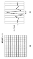
画像回復処理の実空間と周波数空間での特性を図12を用いて説明する。図12において、(a)は画像回復処理前の点像分布関数を、(b)は回復後の点像分布関数をそれぞれ示している。また、図12(c)の401は画像回復処理前のMTF、402は画像回復処理後のMTFを示し、図12(d)の403は画像回復処理前のPTF、404は画像回復処理後のPTFを示している。図12(a)からわかるように、画像回復処理前の点像分布関数は非対称な広がりを有し、この非対称性により、対応するPTFは零ではない値を有する(図12(d)の403)。画像回復処理は、図12(c)の402に示すようにMTFを増幅し、図12(d)の404に示すようにPTFを零に補正するため、画像回復処理後の点像分布関数は図12(b)に示すように対称で先鋭になる。
Image restoration filter not including magnification chromatic aberration correction component The characteristics of image restoration processing in real space and frequency space will be described with reference to FIG. In FIG. 12, (a) shows the point spread function before the image restoration process, and (b) shows the point spread function after the restoration. In FIG. 12C, 401 indicates the MTF before the image recovery process, 402 indicates the MTF after the image recovery process, 403 in FIG. 12D indicates the PTF before the image recovery process, and 404 indicates the image after the image recovery process. PTF is shown. As can be seen from FIG. 12 (a), the point spread function of the pre-image restoration process has an asymmetric spread, this asymmetry, the corresponding PTF have not zero values (FIG. 12 (d) 403 ). Since the image restoration process amplifies the MTF as indicated by 402 in FIG. 12C and corrects the PTF to zero as indicated by 404 in FIG. 12D, the point spread function after the image restoration process is As shown in FIG. 12B, it becomes symmetrical and sharp.
画像回復フィルタは、撮像光学系の光学伝達関数の逆関数(1/H)に基づいて設計した関数を逆フーリエ変換して得ることができる。画像回復フィルタには上述のウィナーフィルタを用いることができるが、他のフィルタを用いてもよい。ウィナーフィルタを用いる場合、以下の式24を逆フーリエ変換することで、コンボリューション処理に用いる実空間の画像回復フィルタを作成することができる。

次に、倍率色収差を考慮した画像回復フィルタの生成について説明する。図13(a)の502は、501の結像位置を基準として平行移動した位置に同形状の点像分布関数として結像した2つの色成分を表している。このときのPTFを図13(b)に示す。図13(b)の601、602は図13(a)の501、502と対応しており、602は位相が傾きをもった直線となっている。画像回復フィルタは、このような直線的なPTFも図3(d)の403のような非直線のPTFも、もととなる光学伝達関数に含まれているため図13(b)の601のように補正することができる。 Next, generation of an image restoration filter taking magnification chromatic aberration into consideration will be described. Reference numeral 502 in FIG. 13A represents two color components formed as a point spread function having the same shape at a position translated from the image forming position 501 as a reference. The PTF at this time is shown in FIG. 601 and 602 in FIG. 13B correspond to 501 and 502 in FIG. 13A, and 602 is a straight line with a phase gradient. The image restoration filter includes such a linear PTF and a non-linear PTF such as 403 in FIG. 3D in the original optical transfer function. Can be corrected as follows.
また、予めPTFから直線成分を除去した光学伝達関数をもとに画像回復フィルタを生成することで、平行移動としての倍率色収差の成分を補正しない画像回復フィルタを生成することができる。一方、実空間で倍率色収差成分を除去する場合、図13(a)の502を501の位置に平行移動して色成分間の差異を低減した点像分布関数を生成し、フーリエ変換することで、同様に倍率色収差の成分を除去した光学伝達関数を生成することができる。実際には501と502の点像分布関数の形状は異なるため、例えば重心を一致させる方法や501と502の差分の二乗平均を最小化するなどして両者を位置合わせすることで、色成分間の差異を低減できる。この光学伝達関数をもとに画像回復フィルタを生成することで、平行移動としての倍率色収差の成分を補正しない画像回復フィルタを生成することができる。 Further, by generating the image restoration filter based on the optical transfer function obtained by removing the linear component from the PTF in advance, it is possible to generate an image restoration filter that does not correct the lateral chromatic aberration component as the parallel movement. On the other hand, when removing the lateral chromatic aberration component in real space, a point spread function is generated by translating 502 in FIG. 13A to the position 501 to reduce the difference between the color components, and performing Fourier transform. Similarly, it is possible to generate an optical transfer function from which the component of chromatic aberration of magnification is removed. Since the shape of the point spread function of 501 and 502 is actually different, for example, by aligning the centers by matching the centroids or minimizing the root mean square of the difference between 501 and 502, Can be reduced. By generating an image restoration filter based on this optical transfer function, an image restoration filter that does not correct the component of lateral chromatic aberration as a translation can be generated.
倍率色収差の成分を補正しない画像回復フィルタを適用することで、倍率色収差を画像回復処理と独立して処理することが可能になる。つまり、色成分ごとの非対称収差の補正および先鋭化と、倍率色収差の平行移動の成分である色ズレの補正とを分離して処理することが可能になる。 By applying an image restoration filter that does not correct the lateral chromatic aberration component, it is possible to process lateral chromatic aberration independently of the image restoration process. That is, the correction and sharpening of the asymmetric aberration for each color component and the correction of the color misregistration that is the component of the parallel movement of the magnification chromatic aberration can be processed separately.
なお、光学伝達関数は同一の撮像状態(ズーム位置や絞りの開口径)であっても撮像光学系の像高(画像の位置)に応じて変化するので、画像回復フィルタは像高に応じて変更して使用することが望ましい。 Since the optical transfer function changes according to the image height (image position) of the image pickup optical system even in the same image pickup state (zoom position or aperture diameter of the stop), the image restoration filter corresponds to the image height. It is desirable to change and use it.
(倍率色収差の検出と補正)
倍率色収差の補正量は、上述のようにPTFの直線成分や点像分布関数の形状など、撮像光学系の設計値から算出することができる。上述のように、本明細書では色ズレと倍率色収差とを同義として用いるので、倍率色収差はGに対するRのズレ量、Gに対するBのズレ量として扱うことができる。
(Detection and correction of lateral chromatic aberration)
The correction amount of the lateral chromatic aberration can be calculated from the design values of the imaging optical system such as the linear component of the PTF and the shape of the point spread function as described above. As described above, in this specification, the color shift and the lateral chromatic aberration are used synonymously, and therefore the lateral chromatic aberration can be treated as an R shift amount with respect to G and a B shift amount with respect to G.
以下、本実施形態における倍率色収差の補正方法を説明する。
倍率色収差による色ズレ量は一般に撮像光学系の光軸中心からの距離を示す像高によって変動する。ここで、ある像高Lにおける色ズレ量Dから、像高Lに対する色ズレ率Mを次式のように定義する。
M=D/L ・・・(式25)
Hereinafter, a method for correcting chromatic aberration of magnification in the present embodiment will be described.
The amount of color shift due to lateral chromatic aberration generally varies depending on the image height indicating the distance from the center of the optical axis of the imaging optical system. Here, from a color shift amount D at a certain image height L, a color shift rate M with respect to the image height L is defined as follows.
M = D / L (Equation 25)
図14(b)に示すように、像高(ここでは図14(a)に示した領域h1〜h8)と色ズレ率とから、像高lと色ズレ率Mとの関係を表す高次の多項近似式F(l)を算出し、これを補正データとする。図14(b)は以下の式26のように3次の多項式により補正データを算出した例である。なお式26においてa、b、cは係数を示している。
M=F(l)=al3 +bl2 +cl ・・・(式26)
As shown in FIG. 14B, a higher order representing the relationship between the
M = F (l) = al 3 + bl 2 + cl (Equation 26)
色ズレの補正は対象色成分の画素位置をシフトすることで行い、具体的には例えば以下に示す方法で補正することができる。
まず、補正したいプレーン(Rプレーン、Bプレーン)の画素(X,Y)において、画素(X,Y)の像高Lと、補正データとから、画素(X,Y)における色ズレ率Mを求める。なお、光学中心に対応する画素が(0,0)の座標系とする。
M=F(L) ・・・(式27)
The color misregistration is corrected by shifting the pixel position of the target color component. Specifically, for example, the color misregistration can be corrected by the following method.
First, in the pixel (X, Y) of the plane (R plane, B plane) to be corrected, the color misregistration rate M in the pixel (X, Y) is calculated from the image height L of the pixel (X, Y) and the correction data. Ask. It is assumed that the pixel corresponding to the optical center is a coordinate system of (0, 0).
M = F (L) (Expression 27)
次に色ズレ補正により生成する画素の座標(X1,Y1)を求める。
X1=M×X ・・・(式28)
Y1=M×Y ・・・(式29)
Next, the coordinates (X1, Y1) of the pixel generated by the color misregistration correction are obtained.
X1 = M × X (Formula 28)
Y1 = M × Y (Formula 29)
補正したいプレーンにおいて上記座標(X1,Y1)に相当する画素値を、一般的な補間処理により生成し、画素(X,Y)の画素値とする。これらを全画素について行うことで、色ズレ補正を行う。このようにして、倍率色収差を補正する。 A pixel value corresponding to the coordinates (X1, Y1) in the plane to be corrected is generated by a general interpolation process, and is set as the pixel value of the pixel (X, Y). By performing these operations for all pixels, color misregistration correction is performed. In this way, lateral chromatic aberration is corrected.
図15は、本発明の第2の実施形態に係る画像処理装置の一例としての撮像装置が有する画像回復処理部111”の機能構成例を示すブロック図である。図15において、第1の実施形態に係る画像回復処理部111と同じ機能ブロックには同じ参照数字を付してある。図2と図15との比較からわかるように、本実施形態ではG成分に対する回復フィルタ適用部が2つあること、倍率色収差補正部(R)1015と倍率色収差補正部(B)1016を有することを特徴とする。
FIG. 15 is a block diagram illustrating a functional configuration example of an image
図16に示すフローチャートを用いて、画像回復処理部111”の動作について説明する。
まずS301で、倍率色収差補正部(R)1015と倍率色収差補正部(B)1016で、R成分とB成分の倍率色収差をそれぞれ補正する。
The operation of the image
First, in step S301, the lateral chromatic aberration correction unit (R) 1015 and the lateral chromatic aberration correction unit (B) 1016 correct the lateral chromatic aberration of the R component and the B component, respectively.
図4(c)及び(d)に示したように、入力されるR成分とB成分は限られた画素にのみ値を持つ状態だが、値を持つ画素のみを使用した補間処理による画素位置のシフトを行なうことで、RAW画像のまま倍率色収差を補正することができる。 As shown in FIGS. 4C and 4D, the input R component and B component have a value only in a limited number of pixels, but the pixel position of the pixel position by the interpolation process using only the pixels having the value is shown. By performing the shift, it is possible to correct the chromatic aberration of magnification while maintaining the RAW image.
G成分の画素補間処理(S201)と、回復前色差情報取得処理(S202)は第1の実施形態で説明したとおりである。 The G component pixel interpolation process (S201) and the pre-recovery color difference information acquisition process (S202) are as described in the first embodiment.
次のS304で、回復フィルタ適用部1005,1006,1017,1018は撮像条件に適した画像回復フィルタを選択する。ただし、本実施形態で用いる画像回復フィルタは、倍率色収差補正のための平行移動成分が除去されている。つまり、画像回復フィルタは倍率色収差補正成分を含んでおらず、収差の非対称性および広がりを補正して画像の先鋭化を行うが、倍率色収差の平行移動成分に関しては補正しない。上述の通り、このような画像回復フィルタを用いることにより、倍率色収差を画像回復処理と独立して処理することが可能になる。つまり、色成分ごとの非対称収差の補正および先鋭化と、倍率色収差の平行移動の成分である色ズレの補正とを分離して処理することが可能になる。
In next S304, the recovery
また、S304においては、選択された画像回復フィルタを必要に応じて補正しても構わない。これは、予め記憶部108に用意しておく画像回復フィルタのデータ数を低減するために、離散的な撮像状態のデータを用意しておいて、画像回復処理を実行する際に、実際の撮像状態に応じて画像回復フィルタを補正することである。また、画像回復フィルタの選択ではなく、画像回復フィルタを生成するために必要な光学伝達関数に関する情報から、撮像状態に応じた画像回復フィルタを生成してもよい。
In S304, the selected image restoration filter may be corrected as necessary. This is because, in order to reduce the number of data of the image restoration filter prepared in advance in the
S305で回復フィルタ適用部1005,1006,1017,1018は、S304で選択もしくは生成した画像回復フィルタを、撮像された入力画像の各色成分に対して適用する。これにより、撮像光学系101の収差による点像分布関数の非対称性を補正し、画像のぼけ成分を除去もしくは低減することができる。
In S305, the recovery
本実施形態では図17(a)(d)(e)で示すように、RAW画像のG成分をさらにベイヤー配列におけるG1、G2の2成分に分離し、回復フィルタ適用部(G1)1017と回復フィルタ適用部(G2)1018で別個に画像回復フィルタを適用する。具体的には、R成分の信号を出力する画素の水平方向に隣接する画素から出力されるG成分の信号をG1成分の信号とし、B成分の信号を出力する画素の水平方向に隣接する画素から出力されるG成分の信号をG2成分の信号とする。 In this embodiment, as shown in FIGS. 17A, 17D, and 17E, the G component of the RAW image is further separated into two components G1 and G2 in the Bayer array, and the recovery filter application unit (G1) 1017 is recovered. A filter application unit (G2) 1018 separately applies the image restoration filter. Specifically, a G component signal output from a pixel adjacent in the horizontal direction of a pixel that outputs an R component signal is a G1 component signal, and a pixel adjacent in the horizontal direction of a pixel that outputs a B component signal The G component signal output from is used as the G2 component signal.
つまり、図17(b)(c)(d)(e)で示したR、B、G1、G2の4つを画像回復成分として扱い、個別に回復フィルタ適用部1005、1006、1017、1018、で画像回復処理(コンボリューション処理)を適用する。
That is, four R, B, G1, and G2 shown in FIGS. 17B, 17C, 17D, and 17E are treated as image restoration components, and restoration
ここで、G成分をさらにG1、G2の2成分に分離して処理する意味を説明する。図18はベイヤー配列の原色カラーフィルタを備える撮像素子における、色成分別の画素配列の空間周波数特性を示す図である。
所定のx,yの範囲について、G成分の画素で光を感知できる画素(白)を「1」、光を感知できない画素(黒)を「0」とする配列m_G(x,y)を求める。同様の配列を、R、B、G1、G2成分についても求め、m_R(x,y)、m_B(x,y)、m_G1(x,y)、m_G2(x,y)とする。m_G(x,y)、m_R(x,y)、m_B(x,y)、m_G1(x,y)、m_G2(x,y)をフーリエ変換したものが図18に示した周波数特性に相当する。
Here, the meaning of further separating the G component into two components G1 and G2 will be described. FIG. 18 is a diagram illustrating a spatial frequency characteristic of a pixel array for each color component in an imaging device including a primary color filter with a Bayer array.
For a predetermined range of x and y, an array m_G (x, y) is obtained in which a pixel (white) that can sense light with a G component pixel is “1” and a pixel that cannot sense light (black) is “0”. . Similar arrangements are also obtained for the R, B, G1, and G2 components, and are set as m_R (x, y), m_B (x, y), m_G1 (x, y), and m_G2 (x, y). The result of Fourier transform of m_G (x, y), m_R (x, y), m_B (x, y), m_G1 (x, y), m_G2 (x, y) corresponds to the frequency characteristics shown in FIG. .
図18(a)はG1成分とG2成分の両方を含んだG成分、すなわち図17(a)の周波数特性を表したものであり、●の位置のみに「1」が存在するくし型関数である。図18(a)に示すG成分の周波数特性は、図17(b)(c)で示したR成分・B成分の周波数特性を示した図18(b)とは異なる。一方、G成分をG1成分とG2成分に分離すると、周波数特性はRやB成分と同様に図18(b)のようになる。 FIG. 18A shows the G component including both the G1 component and the G2 component, that is, the frequency characteristic of FIG. 17A, and is a comb-type function in which “1” exists only at the position of ●. is there. The frequency characteristic of the G component shown in FIG. 18A is different from FIG. 18B showing the frequency characteristics of the R component and B component shown in FIGS. 17B and 17C. On the other hand, when the G component is separated into the G1 component and the G2 component, the frequency characteristics are as shown in FIG.
ベイヤー配列の原色カラーフィルタでは、G画素がR画素やB画素の2倍含まれるため、図18に示すとおりG成分とR,B成分とで周波数特性が異なる。そのため、G成分をG1成分とG2成分に分離せず、R、G、Bの3つの色成分に画像回復フィルタを適用した場合、G成分だけが高周波帯域まで回復される。RGB成分のうちG成分だけが高周波帯域まで回復されると、高周波成分を含む画像領域に、本来存在しなかった偽色が発生することがある。これは、画像の高周波帯域におけるRGB成分の周波数特性の関係が、画像回復処理前と後で変化したことによる。 In the Bayer array primary color filter, G pixels are included twice as many as R pixels and B pixels, and therefore the frequency characteristics of the G component and the R and B components are different as shown in FIG. Therefore, when the image restoration filter is applied to the three color components R, G, and B without separating the G component into the G1 component and the G2 component, only the G component is restored to the high frequency band. When only the G component of the RGB components is recovered to the high frequency band, a false color that did not originally exist may be generated in the image region including the high frequency component. This is because the relationship between the frequency characteristics of the RGB components in the high frequency band of the image has changed before and after the image restoration processing.
このように、画像回復対象成分の周波数特性が異なる場合、画像回復処理によって偽色が発生の原因になる。この偽色は、ベイヤー配列の画像に対する画素補間によって発生する偽色とは異なり、撮像素子によって取得された画素値そのものが変化することで発生する。そのため、画素補間による偽色発生を抑制する手法では画像回復処理によって発生する偽色は抑制できない。 As described above, when the frequency characteristics of the image restoration target components are different, false colors are caused by the image restoration processing. This false color is generated when the pixel value itself acquired by the image sensor changes, unlike the false color generated by pixel interpolation for an image with a Bayer array. For this reason, the method for suppressing the generation of false color due to pixel interpolation cannot suppress the false color generated by the image restoration process.
G成分をG1成分及びG2成分に分離することで、4つの画像回復成分R、G1、G2、Bの画素配列は同じ空間周波数特性を示すようになるため、画像回復処理による偽色の発生を抑えることができる。なお、G成分をG1成分とG2成分に分離しない場合も、G成分に適用する画像回復フィルタの作り方によって、補正されるG成分の周波数帯域をRやB成分に一致させることが可能である。しかし、その場合、回復される周波数帯域はG成分をG1成分とG2成分に分離した場合と同等である。 By separating the G component into the G1 component and the G2 component, the pixel arrangement of the four image restoration components R, G1, G2, and B shows the same spatial frequency characteristics, so that false color generation due to the image restoration processing is prevented. Can be suppressed. Even when the G component is not separated into the G1 component and the G2 component, it is possible to match the frequency band of the G component to be corrected with the R or B component by making an image restoration filter applied to the G component. However, in that case, the recovered frequency band is equivalent to the case where the G component is separated into the G1 component and the G2 component.
以後の処理は第1の実施形態におけるS205〜S209の処理と同様である。S305でG成分をG1成分とG2成分に分離して画像回復フィルタを適用した後は、再度1つのG成分として以降の処理を行なう。 The subsequent processing is the same as the processing of S205 to S209 in the first embodiment. After separating the G component into the G1 component and the G2 component and applying the image restoration filter in S305, the subsequent processing is performed again as one G component.
以上、本実施形態にかかわる画像回復処理部111”の構成及び画像回復処理について説明した。ここで、本実施形態においてS301で倍率色収差補正を行い、S305で倍率色収差補正成分を含まない画像回復フィルタを適用することの作用および効果の例を図19を用いて説明する。
The configuration of the image
図19(a)(b)は、図8に示したような、周辺部に点光源が存在する被写界を撮像した入力における、点光源とその近傍の水平方向における画素値の例を示す模式図である。図19(a)(b)はいずれも上段にR成分とG成分の画素値を、下段には上段で示したR成分とG成分の差分、つまり色差を示している。 FIGS. 19A and 19B show examples of the point light source and the pixel values in the horizontal direction in the vicinity of the input imaged of the object scene in which the point light source exists in the peripheral portion as shown in FIG. It is a schematic diagram. FIGS. 19A and 19B show the pixel values of the R component and the G component in the upper stage, and the difference between the R component and the G component shown in the upper stage, that is, the color difference, in the lower stage.
まず、図19(a)は非合焦時において、倍率色収差補正成分を含まない画像回復フィルタを使用することの作用及び効果を説明するための図である。(a)−1は倍率色収差補正と、倍率色収差補正成分を含まない画像回復フィルタによる画像回復処理を行っていない状態を示し、画像に各収差が残存していることがわかる。G成分、R成分ともにぼけており、さらに倍率色収差により色ズレが発生しているため左右のエッジで色差が発生している。ただし、G成分とR成分のぼけ方は一致している。 First, FIG. 19A is a diagram for explaining the operation and effect of using an image restoration filter that does not include a magnification chromatic aberration correction component when out of focus. (A) -1 indicates a state in which the magnification chromatic aberration correction and the image restoration process by the image restoration filter not including the magnification chromatic aberration correction component are not performed, and it can be seen that each aberration remains in the image. Both the G component and the R component are blurred, and further, color misregistration occurs due to lateral chromatic aberration, so that a color difference occurs between the left and right edges. However, the blurring of the G component and the R component are the same.
倍率色収差補正のみを適用した場合を、(a)−2に示す。G成分、R成分ともにぼけているが、倍率色収差補正により色ズレが解消されている。もともとG成分とR成分のぼけ方は一致していたため、色差は全領域で0である。 The case where only the lateral chromatic aberration correction is applied is shown in (a) -2. Although both the G component and the R component are blurred, the color shift is eliminated by correcting the chromatic aberration of magnification. Since the blurring of the G component and the R component originally matched, the color difference is 0 in the entire region.
倍率色収差補正に加え、倍率色収差補正成分を含まない画像回復フィルタによる画像回復処理を適用した場合を(a)−3に示す。非合焦時の例であるため、ぼけは低減しているが、実際の撮像状態での収差の状態と、画像回復フィルタの対象としている収差の状態が異なるために色付きが発生している。この色付きが本実施形態において抑制の対象となる色付きである。上述のように、本実施形態では、色付き抑制のための画素値調整処理の要否(画素値の補正要否)は、倍率色収差が補正された状態に相当する(a)−2の色差と、画像回復フィルタ適用後の状態に相当する(a)−3の色差の変化に基づいて判定される。 A case where an image restoration process using an image restoration filter not including a magnification chromatic aberration correction component is applied in addition to the magnification chromatic aberration correction is shown in (a) -3. Although the blur is reduced because it is an example at the time of out-of-focus, coloring occurs because the state of aberration in the actual imaging state is different from the state of aberration targeted by the image restoration filter. This coloring is a coloring that is an object of suppression in the present embodiment. As described above, in the present embodiment, whether or not the pixel value adjustment process for suppressing coloring (necessity of pixel value correction) is equivalent to the state in which the chromatic aberration of magnification is corrected is the color difference of (a) -2. And (a) -3 corresponding to the state after application of the image restoration filter.
(a)−2の状態で色差は全領域で0であるため、画像回復フィルタの適用により色差が増大したと判定され、色付き抑制のための画素値調整が必要と決定される。(a)−4は色付き抑制のための画素値調整処理の実行後の状態を示し、画像回復処理によって発生した色付きが適切に抑制され、色差は(a)−2と同様に全領域で0となる。 In the state of (a) -2, since the color difference is 0 in all regions, it is determined that the color difference has increased due to the application of the image restoration filter, and it is determined that the pixel value adjustment for suppressing coloring is necessary. (A) -4 shows a state after the execution of the pixel value adjustment process for suppressing coloring, and coloring generated by the image restoration process is appropriately suppressed, and the color difference is 0 in the entire region as in (a) -2. It becomes.
一方、図19(b)は非合焦時において、倍率色収差補正成分を含んだ画像回復フィルタを使用した場合を示す。(b)−1は(a)−1と同じであり、倍率色収差補正も画像回復フィルタによる画像回復処理も行っていない状態を示している。
この状態から、倍率色収差補正成分を有する画像回復フィルタを適用し、倍率色収差補正と画像回復処理を行った状態を(b)−2に示す。色ズレが消滅し、ぼけは低減されてはいるが、画像回復フィルタの適用により色付きが発生している。(a)−3と同様の状態である。
On the other hand, FIG. 19B shows a case where an image restoration filter including a magnification chromatic aberration correction component is used in the out-of-focus state. (B) -1 is the same as (a) -1 and shows a state where neither the lateral chromatic aberration correction nor the image restoration processing by the image restoration filter is performed.
From this state, (b) -2 shows a state in which an image restoration filter having a magnification chromatic aberration correction component is applied and magnification chromatic aberration correction and image restoration processing are performed. Although the color shift disappears and the blur is reduced, the application of the image restoration filter causes coloring. It is the same state as (a) -3.
倍率色収差補正成分を含んだ画像回復フィルタを使用した場合、色付き抑制のための画素値の補正要否は、画像回復フィルタ適用前の(b)−1での色差と、画像回復フィルタ適用後の(b)−2での色差の変化に基づいて判定する。この場合、左のエッジは色差が一部反転しているため、色付き抑制のために画素値の補正が必要と判定されるが、右のエッジは色差が増大も反転もしていないため、画素値の補正は不要と判定される。 When an image restoration filter including a magnification chromatic aberration correction component is used, whether or not to correct a pixel value for suppression of coloring depends on the color difference in (b) -1 before application of the image restoration filter and after application of the image restoration filter. (B) The determination is made based on the change in color difference at -2. In this case, since the color difference of the left edge is partially inverted, it is determined that the pixel value needs to be corrected to suppress coloring, but the right edge does not increase or invert the color difference. Is determined to be unnecessary.
(b)−3は色付き抑制のための画素値調整処理が実行された状態を示し、左のエッジは色付きが抑制されているが、右のエッジは色付きが抑制されずそのまま残っている。 (B) -3 shows a state in which pixel value adjustment processing for suppressing coloring is performed, and coloring of the left edge is suppressed, but coloring of the right edge remains without being suppressed.
このように本実施形態では、画像回復処理の前に倍率色収差補正を行い、その後、倍率色収差補正成分を含まない画像回復フィルタを適用して画像回復処理を行うことで、第1の実施形態による効果に加え、より高精度な色付き抑制が可能となる。 As described above, according to the first embodiment, the magnification chromatic aberration correction is performed before the image restoration process, and then the image restoration process is performed by applying the image restoration filter that does not include the magnification chromatic aberration correction component. In addition to the effect, it is possible to suppress coloring with higher accuracy.
また、G成分をG1成分とG2成分に分離して画像回復処理を適用することで、RAW画像における各成分の周波数特性が等しくなり、画像回復処理による色付きをさらに抑制することができる。 In addition, by applying the image restoration process by separating the G component into the G1 component and the G2 component, the frequency characteristics of each component in the RAW image become equal, and coloring due to the image restoration process can be further suppressed.
なお、本実施形態では、基準の色成分であるG成分をG1成分とG2成分に分離する構成と、倍率色収差補正と倍率色収差補正成分を含まない画像回復フィルタの組み合わせとを両方備える画像回復処理部111”について説明した。しかし、一方だけを用いることもでき、個々の効果を享受できる。
また、本実施形態においても、図11を用いて説明した第1の実施形態の変形例のように、画素間引き部を設けた構成とすることができる。
In the present embodiment, an image restoration process includes both a configuration in which the G component that is a reference color component is separated into a G1 component and a G2 component, and a combination of magnification chromatic aberration correction and an image restoration filter that does not include the magnification chromatic aberration correction component. The
Also in the present embodiment, a configuration in which a pixel thinning portion is provided as in the modification of the first embodiment described with reference to FIG.
(その他の実施形態)
また、本発明は、以下の処理を実行することによっても実現される。即ち、上述した実施形態の機能を実現するソフトウェア(プログラム)を、ネットワーク又は各種記憶媒体を介してシステム或いは装置に供給し、そのシステム或いは装置のコンピュータ(またはCPUやMPU等)がプログラムを読み出して実行する処理である。
(Other embodiments)
The present invention can also be realized by executing the following processing. That is, software (program) that realizes the functions of the above-described embodiments is supplied to a system or apparatus via a network or various storage media, and a computer (or CPU, MPU, or the like) of the system or apparatus reads the program. It is a process to be executed.
Claims (15)
前記画像のうち予め定めた基準の色成分について、画素補間処理を行う第1の画素補間手段と、
前記画像のうち前記基準の色成分以外の色成分の各々について、値を有する画素と前記画素補間処理後の前記基準の色成分の対応する画素とから、色差を取得する第1の取得手段と、
前記撮像光学系の収差を示す関数に基づいた画像回復フィルタを、前記画像の色成分の各々に対して適用する画像回復処理手段と、
前記画像回復フィルタが適用された画像のうち前記基準の色成分について、画素補間処理を行う第2の画素補間手段と、
前記画像回復フィルタが適用された画像のうち前記基準の色成分以外の色成分の各々について、値を有する画素と前記第2の画素補間手段による画素補間処理後の前記基準の色成分の対応する画素とから、色差を取得する第2の取得手段と、
前記第1の取得手段と前記第2の取得手段が取得した前記色差の変化に応じて、前記画像回復フィルタが適用された画像の画素値を補正する画素値補正手段と、
を有し、
前記画素値補正手段による画素値の補正がなされるまでは、前記画像および前記画像回復フィルタが適用された画像のいずれについても、前記基準の色成分以外の色成分についての画素補間処理を行わないことを特徴とする画像処理装置。 An image processing device for correcting deterioration of image quality due to aberration of an imaging optical system of the imaging device in an image captured by the imaging device and each pixel having one color component,
First pixel interpolation means for performing pixel interpolation processing on a predetermined reference color component of the image;
First acquisition means for acquiring a color difference for each color component other than the reference color component in the image from a pixel having a value and a corresponding pixel of the reference color component after the pixel interpolation processing; ,
Image restoration processing means for applying an image restoration filter based on a function indicating aberration of the imaging optical system to each of the color components of the image;
Second pixel interpolation means for performing pixel interpolation processing on the reference color component of the image to which the image restoration filter is applied;
For each color component other than the reference color component in the image to which the image restoration filter is applied, the pixel having a value and the reference color component after pixel interpolation processing by the second pixel interpolation unit correspond to each other. Second acquisition means for acquiring a color difference from the pixel;
A pixel value correcting unit that corrects a pixel value of an image to which the image restoration filter is applied according to a change in the color difference acquired by the first acquiring unit and the second acquiring unit;
I have a,
Until the pixel value is corrected by the pixel value correcting unit, pixel interpolation processing is not performed for color components other than the reference color component for both the image and the image to which the image restoration filter is applied. An image processing apparatus.
前記第1の取得手段は前記倍率色収差が補正された色成分の各々について前記色差を取得し、
前記画像回復処理手段は、倍率色収差の補正を行わない画像回復フィルタを適用することを特徴とする請求項1又は請求項2に記載の画像処理装置。 A magnification chromatic aberration correction unit that corrects magnification chromatic aberration of the imaging optical system for each of the color components other than the reference color component in the image,
The first acquisition means acquires the color difference for each color component in which the magnification chromatic aberration is corrected,
The image processing apparatus according to claim 1, wherein the image restoration processing unit applies an image restoration filter that does not correct lateral chromatic aberration.
前記基準の色成分がG成分であることを特徴とする請求項1乃至請求項3のいずれか1項に記載の画像処理装置。 The image is captured by an image sensor having a primary color filter with a Bayer array,
The image processing apparatus according to claim 1, wherein the reference color component is a G component.
前記光学像を撮像する撮像素子と、
請求項1乃至請求項12のいずれか1項に記載の画像処理装置とを有することを特徴とする撮像装置。 An imaging optical system that forms an optical image of the subject;
An image sensor that captures the optical image;
An image pickup apparatus comprising: the image processing apparatus according to claim 1.
前記画像処理装置の第1の画素補間手段が、前記画像のうち予め定めた基準の色成分について、画素補間処理を行う第1の画素補間工程と、
前記画像処理装置の第1の取得手段が、前記画像のうち前記基準の色成分以外の色成分の各々について、値を有する画素と前記画素補間処理後の前記基準の色成分の対応する画素とから、色差を取得する第1の取得工程と、
前記画像処理装置の画像回復処理手段が、前記撮像光学系の収差を示す関数に基づいた画像回復フィルタを、前記画像の色成分の各々に対して適用する画像回復処理工程と、
前記画像処理装置の第2の画素補間手段が、前記画像回復フィルタが適用された画像のうち前記基準の色成分について画素補間処理を行う第2の画素補間工程と、
前記画像処理装置の第2の取得手段が、前記画像回復フィルタが適用された画像のうち前記基準の色成分以外の色成分の各々について、値を有する画素と前記第2の画素補間手段による画素補間処理後の前記基準の色成分の対応する画素とから、色差を取得する第2の取得工程と、
前記画像処理装置の画素値補正手段が、前記第1の取得工程と前記第2の取得工程で取得された前記色差の変化に応じて、前記画像回復フィルタが適用された画像の画素値を補正する画素値補正工程とを有し、
前記画素値補正工程によってる画素値の補正がなされるまでは、前記画像および前記画像回復フィルタが適用された画像のいずれについても、前記基準の色成分以外の色成分についての画素補間処理を行わないこと、を特徴とする画像処理方法。 An image processing method executed by an image processing apparatus for correcting image quality degradation due to aberration of an imaging optical system of the imaging apparatus in an image captured by the imaging apparatus and each pixel having one color component. And
A first pixel interpolation step in which a first pixel interpolation unit of the image processing apparatus performs a pixel interpolation process on a predetermined reference color component in the image;
The first acquisition unit of the image processing device includes a pixel having a value and a pixel corresponding to the reference color component after the pixel interpolation processing for each color component other than the reference color component in the image. From the first acquisition step of acquiring the color difference,
An image restoration processing step in which the image restoration processing means of the image processing apparatus applies an image restoration filter based on a function indicating the aberration of the imaging optical system to each of the color components of the image;
A second pixel interpolation step in which a second pixel interpolation unit of the image processing device performs a pixel interpolation process on the reference color component in the image to which the image restoration filter is applied;
The second acquisition unit of the image processing apparatus includes a pixel having a value and a pixel by the second pixel interpolation unit for each color component other than the reference color component in the image to which the image restoration filter is applied. A second acquisition step of acquiring a color difference from the corresponding pixel of the reference color component after the interpolation processing;
The pixel value correcting unit of the image processing device corrects the pixel value of the image to which the image restoration filter is applied according to the change in the color difference acquired in the first acquisition step and the second acquisition step. and a pixel value correction step of,
Until the pixel value is corrected by the pixel value correcting step, pixel interpolation processing is performed for color components other than the reference color component for both the image and the image to which the image restoration filter is applied. And an image processing method characterized by not .
Priority Applications (5)
| Application Number | Priority Date | Filing Date | Title |
|---|---|---|---|
| JP2011189326A JP5818586B2 (en) | 2011-08-31 | 2011-08-31 | Image processing apparatus and image processing method |
| US13/591,609 US8971622B2 (en) | 2011-08-31 | 2012-08-22 | Image processing apparatus, image capture apparatus, and image processing method |
| EP12182461.9A EP2566161B1 (en) | 2011-08-31 | 2012-08-30 | Image processing apparatus and method |
| RU2012137089/08A RU2523965C2 (en) | 2011-08-31 | 2012-08-30 | Image processing device, image capturing device and image processing method |
| CN201210320746.1A CN102970459B (en) | 2011-08-31 | 2012-08-31 | Image processing apparatus, image capture apparatus, and image processing method |
Applications Claiming Priority (1)
| Application Number | Priority Date | Filing Date | Title |
|---|---|---|---|
| JP2011189326A JP5818586B2 (en) | 2011-08-31 | 2011-08-31 | Image processing apparatus and image processing method |
Publications (3)
| Publication Number | Publication Date |
|---|---|
| JP2013051599A JP2013051599A (en) | 2013-03-14 |
| JP2013051599A5 JP2013051599A5 (en) | 2014-10-16 |
| JP5818586B2 true JP5818586B2 (en) | 2015-11-18 |
Family
ID=46754340
Family Applications (1)
| Application Number | Title | Priority Date | Filing Date |
|---|---|---|---|
| JP2011189326A Active JP5818586B2 (en) | 2011-08-31 | 2011-08-31 | Image processing apparatus and image processing method |
Country Status (5)
| Country | Link |
|---|---|
| US (1) | US8971622B2 (en) |
| EP (1) | EP2566161B1 (en) |
| JP (1) | JP5818586B2 (en) |
| CN (1) | CN102970459B (en) |
| RU (1) | RU2523965C2 (en) |
Cited By (1)
| Publication number | Priority date | Publication date | Assignee | Title |
|---|---|---|---|---|
| CN106103999B (en) * | 2014-09-16 | 2018-05-15 | Kyb株式会社 | Pump installation |
Families Citing this family (24)
| Publication number | Priority date | Publication date | Assignee | Title |
|---|---|---|---|---|
| CN104969545B (en) * | 2013-02-05 | 2018-03-20 | 富士胶片株式会社 | Image processing apparatus, camera device, image processing method and program |
| JP5833794B2 (en) * | 2013-03-27 | 2015-12-16 | 富士フイルム株式会社 | Imaging device |
| CN104704806B (en) | 2013-03-28 | 2017-08-29 | 富士胶片株式会社 | Image processing apparatus, camera device and image processing method |
| WO2014155754A1 (en) * | 2013-03-28 | 2014-10-02 | 富士フイルム株式会社 | Image-processing device, image-capturing device, image-processing method, program, and recording medium |
| JP5961149B2 (en) * | 2013-08-26 | 2016-08-02 | キヤノン株式会社 | Image processing apparatus and control method thereof |
| JP6327922B2 (en) * | 2014-04-25 | 2018-05-23 | キヤノン株式会社 | Image processing apparatus, image processing method, and program |
| JP6486076B2 (en) * | 2014-11-10 | 2019-03-20 | キヤノン株式会社 | Image processing apparatus and image processing method |
| CN106999019B (en) * | 2014-11-19 | 2018-10-19 | 奥林巴斯株式会社 | Image processing apparatus, image processing method, recording medium and endoscope apparatus |
| JP2016170122A (en) * | 2015-03-13 | 2016-09-23 | キヤノン株式会社 | Measurement device |
| JP6512893B2 (en) * | 2015-03-26 | 2019-05-15 | キヤノン株式会社 | IMAGE PROCESSING APPARATUS, IMAGING APPARATUS, IMAGE PROCESSING METHOD, AND COMPUTER PROGRAM |
| JP6247795B2 (en) * | 2015-04-23 | 2017-12-13 | 富士フイルム株式会社 | Image processing apparatus, imaging apparatus, image processing method, and program |
| JP6525718B2 (en) * | 2015-05-11 | 2019-06-05 | キヤノン株式会社 | Image processing apparatus, control method therefor, and control program |
| WO2017056823A1 (en) * | 2015-09-28 | 2017-04-06 | 株式会社日立国際電気 | Image pickup device and image pickup method |
| JP6872103B2 (en) * | 2016-05-11 | 2021-05-19 | 富士フイルムビジネスイノベーション株式会社 | Change degree derivation device, change degree derivation method and program |
| EP3493527B1 (en) * | 2017-11-30 | 2019-09-25 | Axis AB | Method, apparatus and system for detecting and reducing the effects of color fringing in digital video acquired by a camera |
| JP7137313B2 (en) | 2018-02-15 | 2022-09-14 | キヤノン株式会社 | Output device, image processing method and program |
| US10972714B2 (en) * | 2018-02-15 | 2021-04-06 | Canon Kabushiki Kaisha | Image processing apparatus, image processing method and storage medium for storing program |
| CN111815720B (en) * | 2019-04-12 | 2024-07-12 | 北京地平线机器人技术研发有限公司 | Image processing method and device, readable storage medium and electronic equipment |
| US11216981B2 (en) | 2019-07-26 | 2022-01-04 | Cnh Industrial America Llc | System and method for calibrating image data during an agricultural operation using a color indicator |
| US11350063B2 (en) | 2020-04-14 | 2022-05-31 | Apple Inc. | Circuit for correcting lateral chromatic abberation |
| US11176643B1 (en) * | 2020-05-04 | 2021-11-16 | Apple Inc. | Circuit for correcting chromatic aberration through sharpening |
| US11763421B2 (en) | 2021-01-07 | 2023-09-19 | Apple Inc. | Circuit for combined down sampling and correction of image data |
| CN116547979A (en) * | 2021-01-15 | 2023-08-04 | 华为技术有限公司 | Image processing method and related device |
| CN114581380B (en) * | 2022-02-16 | 2024-08-20 | 合肥埃科光电科技股份有限公司 | FPGA-based dispersion correction method and storage medium |
Family Cites Families (18)
| Publication number | Priority date | Publication date | Assignee | Title |
|---|---|---|---|---|
| US4663655A (en) * | 1985-08-05 | 1987-05-05 | Polaroid Corporation | Method and apparatus for reconstructing missing color samples |
| US4774565A (en) * | 1987-08-24 | 1988-09-27 | Polaroid Corporation | Method and apparatus for reconstructing missing color samples |
| JP3609525B2 (en) * | 1996-03-18 | 2005-01-12 | コニカミノルタビジネステクノロジーズ株式会社 | Image processing device |
| JP3532368B2 (en) | 1996-12-10 | 2004-05-31 | 富士写真フイルム株式会社 | Endoscope |
| US7053908B2 (en) * | 2001-04-12 | 2006-05-30 | Polaroid Corporation | Method and apparatus for sensing and interpolating color image data |
| US8339462B2 (en) | 2008-01-28 | 2012-12-25 | DigitalOptics Corporation Europe Limited | Methods and apparatuses for addressing chromatic abberations and purple fringing |
| JP4479457B2 (en) * | 2004-05-27 | 2010-06-09 | ソニー株式会社 | Image processing apparatus, image processing method, and computer program |
| JP5071104B2 (en) * | 2005-03-04 | 2012-11-14 | 株式会社ニコン | Image processing apparatus, image processing program, image processing method, and electronic camera for correcting color misregistration |
| US7920200B2 (en) | 2005-06-07 | 2011-04-05 | Olympus Corporation | Image pickup device with two cylindrical lenses |
| JP5222472B2 (en) * | 2006-07-14 | 2013-06-26 | イーストマン コダック カンパニー | Image processing apparatus, image restoration method, and program |
| RU2352988C1 (en) * | 2007-09-03 | 2009-04-20 | Государственное образовательное учреждение высшего профессионального образования Курский государственный технический университет | Method for correction of chromatic aberration of optical subsystem of technical vision system |
| JP5045421B2 (en) * | 2007-12-21 | 2012-10-10 | ソニー株式会社 | Imaging apparatus, color noise reduction method, and color noise reduction program |
| JP4911628B2 (en) | 2008-01-28 | 2012-04-04 | 株式会社リコー | Image processing method, image processing apparatus, and image pickup apparatus |
| JP5078147B2 (en) | 2008-03-04 | 2012-11-21 | 株式会社リコー | Image processing apparatus and image pickup apparatus |
| JP4986965B2 (en) * | 2008-09-30 | 2012-07-25 | キヤノン株式会社 | Image processing method, image processing apparatus, image processing program, and imaging apparatus |
| JP4891301B2 (en) * | 2008-09-30 | 2012-03-07 | キヤノン株式会社 | Image processing method, image processing apparatus, and imaging apparatus |
| JP5248980B2 (en) | 2008-10-27 | 2013-07-31 | キヤノン株式会社 | Imaging apparatus, control method thereof, and program |
| JP5523017B2 (en) | 2009-08-20 | 2014-06-18 | キヤノン株式会社 | Image processing apparatus and image processing method |
-
2011
- 2011-08-31 JP JP2011189326A patent/JP5818586B2/en active Active
-
2012
- 2012-08-22 US US13/591,609 patent/US8971622B2/en active Active
- 2012-08-30 RU RU2012137089/08A patent/RU2523965C2/en active
- 2012-08-30 EP EP12182461.9A patent/EP2566161B1/en active Active
- 2012-08-31 CN CN201210320746.1A patent/CN102970459B/en active Active
Cited By (1)
| Publication number | Priority date | Publication date | Assignee | Title |
|---|---|---|---|---|
| CN106103999B (en) * | 2014-09-16 | 2018-05-15 | Kyb株式会社 | Pump installation |
Also Published As
| Publication number | Publication date |
|---|---|
| RU2012137089A (en) | 2014-03-10 |
| EP2566161A2 (en) | 2013-03-06 |
| EP2566161A3 (en) | 2013-04-17 |
| JP2013051599A (en) | 2013-03-14 |
| RU2523965C2 (en) | 2014-07-27 |
| EP2566161B1 (en) | 2016-02-10 |
| US8971622B2 (en) | 2015-03-03 |
| CN102970459B (en) | 2015-07-08 |
| US20130050544A1 (en) | 2013-02-28 |
| CN102970459A (en) | 2013-03-13 |
Similar Documents
| Publication | Publication Date | Title |
|---|---|---|
| JP5818586B2 (en) | Image processing apparatus and image processing method | |
| JP5868076B2 (en) | Image processing apparatus and image processing method | |
| JP5824297B2 (en) | Image processing apparatus and method, and imaging apparatus | |
| JP6327922B2 (en) | Image processing apparatus, image processing method, and program | |
| JP6525718B2 (en) | Image processing apparatus, control method therefor, and control program | |
| JP5409589B2 (en) | Image processing method, image processing program, image processing apparatus, and imaging apparatus | |
| KR101536162B1 (en) | Image processing apparatus and method | |
| JP5441652B2 (en) | Image processing method, image processing apparatus, imaging apparatus, and image processing program | |
| JP2013051599A5 (en) | ||
| JP2010086138A (en) | Image processing method, image processing apparatus, and image pickup apparatus | |
| JP2013020610A (en) | Image processing apparatus, image processing method and program | |
| JP5653464B2 (en) | Imaging apparatus, image processing apparatus, image processing method, image processing program, and storage medium | |
| JP5425135B2 (en) | Image processing method, image processing apparatus, imaging apparatus, and image processing program | |
| JP5645981B2 (en) | Imaging apparatus, image processing apparatus, image processing method, image processing program, and storage medium | |
| JP5425136B2 (en) | Image processing method, image processing apparatus, imaging apparatus, and image processing program | |
| JP2020201694A (en) | Image processing device, imaging device, image processing method, program, and storage medium | |
| JP2015198380A (en) | Image processing system, imaging apparatus, image processing program, and image processing method | |
| JP2023119413A (en) | Image processing apparatus and method, imaging apparatus, program, and storage medium | |
| US20240144536A1 (en) | Image processing device, image processing method, and storage medium | |
| JP6238673B2 (en) | Image processing apparatus, imaging apparatus, imaging system, image processing method, image processing program, and storage medium | |
| JP2018107541A (en) | Image processing apparatus, imaging device, image processing method, and image processing program | |
| JP2017126952A (en) | Image processing unit, imaging apparatus, and image processing program | |
| JP6552375B2 (en) | IMAGE PROCESSING DEVICE, IMAGING DEVICE, AND IMAGE PROCESSING PROGRAM | |
| WO2011121761A1 (en) | Image processing apparatus and image capturing apparatus using same | |
| JP2022161527A (en) | Image processing method, image processing apparatus, imaging device, and program |
Legal Events
| Date | Code | Title | Description |
|---|---|---|---|
| A521 | Request for written amendment filed |
Free format text: JAPANESE INTERMEDIATE CODE: A523 Effective date: 20140829 |
|
| A621 | Written request for application examination |
Free format text: JAPANESE INTERMEDIATE CODE: A621 Effective date: 20140829 |
|
| A977 | Report on retrieval |
Free format text: JAPANESE INTERMEDIATE CODE: A971007 Effective date: 20150413 |
|
| A131 | Notification of reasons for refusal |
Free format text: JAPANESE INTERMEDIATE CODE: A131 Effective date: 20150417 |
|
| A521 | Request for written amendment filed |
Free format text: JAPANESE INTERMEDIATE CODE: A523 Effective date: 20150611 |
|
| TRDD | Decision of grant or rejection written | ||
| A01 | Written decision to grant a patent or to grant a registration (utility model) |
Free format text: JAPANESE INTERMEDIATE CODE: A01 Effective date: 20150831 |
|
| A61 | First payment of annual fees (during grant procedure) |
Free format text: JAPANESE INTERMEDIATE CODE: A61 Effective date: 20150929 |
|
| R151 | Written notification of patent or utility model registration |
Ref document number: 5818586 Country of ref document: JP Free format text: JAPANESE INTERMEDIATE CODE: R151 |