JP5868076B2 - Image processing apparatus and image processing method - Google Patents
Image processing apparatus and image processing method Download PDFInfo
- Publication number
- JP5868076B2 JP5868076B2 JP2011189325A JP2011189325A JP5868076B2 JP 5868076 B2 JP5868076 B2 JP 5868076B2 JP 2011189325 A JP2011189325 A JP 2011189325A JP 2011189325 A JP2011189325 A JP 2011189325A JP 5868076 B2 JP5868076 B2 JP 5868076B2
- Authority
- JP
- Japan
- Prior art keywords
- image
- component
- image restoration
- chromatic aberration
- color
- Prior art date
- Legal status (The legal status is an assumption and is not a legal conclusion. Google has not performed a legal analysis and makes no representation as to the accuracy of the status listed.)
- Active
Links
- 238000012545 processing Methods 0.000 title claims description 132
- 238000003672 processing method Methods 0.000 title claims description 6
- 230000004075 alteration Effects 0.000 claims description 155
- 238000003384 imaging method Methods 0.000 claims description 111
- 230000003287 optical effect Effects 0.000 claims description 101
- 238000012937 correction Methods 0.000 claims description 74
- 238000012546 transfer Methods 0.000 claims description 29
- 230000008859 change Effects 0.000 claims description 9
- 230000015556 catabolic process Effects 0.000 claims description 5
- 238000006731 degradation reaction Methods 0.000 claims description 5
- 230000006866 deterioration Effects 0.000 claims description 5
- 238000000034 method Methods 0.000 description 72
- 230000008569 process Effects 0.000 description 54
- 238000004040 coloring Methods 0.000 description 47
- 238000011084 recovery Methods 0.000 description 28
- 230000000694 effects Effects 0.000 description 11
- 238000010586 diagram Methods 0.000 description 9
- 238000001514 detection method Methods 0.000 description 6
- 238000003860 storage Methods 0.000 description 6
- 230000001629 suppression Effects 0.000 description 5
- 206010010071 Coma Diseases 0.000 description 4
- 230000007423 decrease Effects 0.000 description 4
- 238000013461 design Methods 0.000 description 3
- 238000009826 distribution Methods 0.000 description 3
- 238000003708 edge detection Methods 0.000 description 3
- 238000004519 manufacturing process Methods 0.000 description 3
- 238000001228 spectrum Methods 0.000 description 3
- 230000007246 mechanism Effects 0.000 description 2
- 230000010363 phase shift Effects 0.000 description 2
- 238000013519 translation Methods 0.000 description 2
- 201000009310 astigmatism Diseases 0.000 description 1
- 238000003702 image correction Methods 0.000 description 1
- 230000006872 improvement Effects 0.000 description 1
- 230000010354 integration Effects 0.000 description 1
- 230000002093 peripheral effect Effects 0.000 description 1
- 230000005855 radiation Effects 0.000 description 1
- 230000009467 reduction Effects 0.000 description 1
- 230000003595 spectral effect Effects 0.000 description 1
Images


Classifications
-
- H—ELECTRICITY
- H04—ELECTRIC COMMUNICATION TECHNIQUE
- H04N—PICTORIAL COMMUNICATION, e.g. TELEVISION
- H04N9/00—Details of colour television systems
- H04N9/64—Circuits for processing colour signals
- H04N9/646—Circuits for processing colour signals for image enhancement, e.g. vertical detail restoration, cross-colour elimination, contour correction, chrominance trapping filters
-
- G06T5/80—
-
- H—ELECTRICITY
- H04—ELECTRIC COMMUNICATION TECHNIQUE
- H04N—PICTORIAL COMMUNICATION, e.g. TELEVISION
- H04N1/00—Scanning, transmission or reproduction of documents or the like, e.g. facsimile transmission; Details thereof
- H04N1/46—Colour picture communication systems
- H04N1/56—Processing of colour picture signals
- H04N1/60—Colour correction or control
- H04N1/6027—Correction or control of colour gradation or colour contrast
-
- H—ELECTRICITY
- H04—ELECTRIC COMMUNICATION TECHNIQUE
- H04N—PICTORIAL COMMUNICATION, e.g. TELEVISION
- H04N25/00—Circuitry of solid-state image sensors [SSIS]; Control thereof
- H04N25/60—Noise processing, e.g. detecting, correcting, reducing or removing noise
- H04N25/61—Noise processing, e.g. detecting, correcting, reducing or removing noise the noise originating only from the lens unit, e.g. flare, shading, vignetting or "cos4"
- H04N25/615—Noise processing, e.g. detecting, correcting, reducing or removing noise the noise originating only from the lens unit, e.g. flare, shading, vignetting or "cos4" involving a transfer function modelling the optical system, e.g. optical transfer function [OTF], phase transfer function [PhTF] or modulation transfer function [MTF]
- H04N25/6153—Noise processing, e.g. detecting, correcting, reducing or removing noise the noise originating only from the lens unit, e.g. flare, shading, vignetting or "cos4" involving a transfer function modelling the optical system, e.g. optical transfer function [OTF], phase transfer function [PhTF] or modulation transfer function [MTF] for colour signals
-
- G—PHYSICS
- G06—COMPUTING; CALCULATING OR COUNTING
- G06T—IMAGE DATA PROCESSING OR GENERATION, IN GENERAL
- G06T2207/00—Indexing scheme for image analysis or image enhancement
- G06T2207/10—Image acquisition modality
- G06T2207/10024—Color image
Description
本発明は、画像処理装置及び画像処理方法に関し、特に画像回復処理を用いた画像補正技術に関する。 The present invention relates to an image processing apparatus and an image processing method, and more particularly to an image correction technique using an image restoration process.
撮像装置で被写体を撮像して得られた画像には、特に撮像光学系の収差の影響による画質劣化が生じている。例えば、画像のぼけは、撮像光学系の球面収差、コマ収差、像面湾曲、非点収差等による画質劣化である。光の波としての性質である回折の影響を無視すれば、被写体の一点から出た光束は収差のない撮像光学系によって撮像面上で同じ大きさの一点(集光点)に結像される。しかしながら実際には、回折の影響に加え、撮像光学系の収差により、集光点から広がりをもって結像される。 In the image obtained by imaging the subject with the imaging device, image quality deterioration is caused particularly by the influence of the aberration of the imaging optical system. For example, image blur is image quality degradation due to spherical aberration, coma aberration, field curvature, astigmatism, and the like of the imaging optical system. Ignoring the effects of diffraction which is wave nature of light, it is imaged light beam emitted from one point of an object by aberration-free imaging optical system to a point of the same size on the imaging surface (condensing point) . However, in practice, in addition to the influence of diffraction, the image is spread from the focal point due to the aberration of the imaging optical system.
撮像光学系の点像分布関数(PSF: Point Spread Function)は、集光点付近の強度分布、すなわち回折および撮像光学系の収差による像のぼけを表すため、ぼけ成分と呼ぶことにする。このぼけ成分は、いわゆるピントがずれていることによるぼけではなく、ピントが合っていても、光の回折や撮像光学系の収差によって生じるぼけを意味する。 The point spread function (PSF) of the imaging optical system is referred to as a blur component because it represents the intensity distribution near the condensing point, that is, the blur of the image due to diffraction and aberration of the imaging optical system. This blur component means not a blur caused by so-called out-of-focus, but a blur caused by diffraction of light or aberration of the imaging optical system even when the subject is in focus.
また、カラー画像での色にじみも、撮像光学系の軸上色収差、色の球面収差、色のコマ収差に起因するものに関しては、光の波長に応じたぼけ方の相違ということができる。また、横方向の色ズレも、光学系の倍率色収差に起因したものに関しては、光の波長に応じた撮像倍率の相違による位置ずれまたは位相ずれということができる。 Further, color blur in a color image can also be said to be a difference in blurring depending on the wavelength of light with respect to those caused by axial chromatic aberration, color spherical aberration, and color coma aberration of the imaging optical system. In addition, the lateral color misregistration can also be referred to as a positional shift or a phase shift due to a difference in imaging magnification according to the wavelength of light.
点像分布関数をフーリエ変換して得られる光学伝達関数(OTF: Optical Transfer Function)は、収差の周波数成分情報であり、複素数で表される。光学伝達関数の絶対値、即ち振幅成分をMTF(Modulation Transfer Function)と呼び、位相成分をPTF(Phase Transfer Function)と呼ぶ。MTF、PTFはそれぞれ収差による画像劣化の振幅成分および位相成分の周波数特性である。ここでは、位相成分PTFを位相角として以下の式で表す。なお、Re(OTF)、Im(OTF)は、それぞれ光学伝達関数の実部、虚部を表す。
PTF=tan-1(Im(OTF)/Re(OTF)) ・・・(式1)
An optical transfer function (OTF) obtained by Fourier transform of the point spread function is frequency component information of aberration and is represented by a complex number. The absolute value of the optical transfer function, that is, the amplitude component is called MTF (Modulation Transfer Function), and the phase component is called PTF (Phase Transfer Function). MTF and PTF are frequency characteristics of an amplitude component and a phase component of image degradation due to aberration, respectively. Here, the phase component PTF is expressed as the phase angle by the following equation. Re (OTF) and Im (OTF) represent the real part and the imaginary part of the optical transfer function, respectively.
PTF = tan −1 (Im (OTF) / Re (OTF)) (Formula 1)
このように、撮像光学系の光学伝達関数が画像の振幅成分と位相成分の両方を劣化させるため、被写体像の各点は、コマ収差がある場合のように、集光点に対して非対称にぼけている。 In this way, since the optical transfer function of the imaging optical system degrades both the amplitude component and the phase component of the image, each point of the subject image is asymmetric with respect to the focal point as in the case where there is coma aberration. I am blurred.
また、倍率色収差は、光の波長ごとの結像倍率の相違により結像位置がずれる現象である。通常撮像素子にはRGBのカラーモザイクフィルタが設けられており、各画素ではRGBのいずれか一つの色成分を取得するように構成されている。従って、Rの波長、Gの波長、及びBの波長間で結像位置がずれることはもとより、取得した各色成分内にも波長ごとの結像位置のずれ、即ち位相ずれによる像の広がりが発生する。よって、厳密には倍率色収差は単なる平行シフトの色ズレではないが、特に説明が無い限り本明細書では色ズレと倍率色収差とを同義として用いる。 Further, lateral chromatic aberration is a phenomenon in which the imaging position is shifted due to the difference in imaging magnification for each wavelength of light. Usually, an RGB color mosaic filter is provided in the image sensor, and each pixel is configured to acquire any one of RGB color components. Therefore, not only does the imaging position shift between the R wavelength, G wavelength, and B wavelength, but also the image position shift for each wavelength within the acquired color components, that is, the spread of the image due to phase shift occurs. To do. Therefore, strictly speaking, the lateral chromatic aberration is not a simple parallel shift color shift, but unless otherwise specified, in this specification, the color shift and the lateral chromatic aberration are used synonymously.
撮像光学系の光学伝達関数の情報を用い、振幅成分(MTF)および位相成分(PTF)の劣化を補正する、画像回復や画像復元と呼ばれる方法が知られている。そのため、以下では、撮像光学系の光学伝達関数の情報を用いて画像の劣化を補正する処理を画像回復処理と呼ぶ。 There is known a method called image restoration or image restoration that corrects deterioration of an amplitude component (MTF) and a phase component (PTF) using information of an optical transfer function of an imaging optical system. Therefore, in the following, processing for correcting image degradation using information on the optical transfer function of the imaging optical system is referred to as image restoration processing.
ここで、画像回復処理の概要を示す。劣化した画像をg(x,y)、元の画像をf(x,y)、撮像光学系の光学伝達関数を逆フーリエ変換したものである点像分布関数をh(x,y)としたとき、以下の式が成り立つ。ただし、演算子”*”はコンボリューションを示し、(x,y)は画像上の座標を示すものとする。
g(x,y)=h(x,y)*f(x,y) ・・・(式2)
Here, an outline of the image restoration processing is shown. The degraded image is g (x, y), the original image is f (x, y), and the point spread function obtained by inverse Fourier transform of the optical transfer function of the imaging optical system is h (x, y). When the following equation holds: Here, the operator “*” indicates convolution, and (x, y) indicates the coordinates on the image.
g (x, y) = h (x, y) * f (x, y) (Expression 2)
また、この式をフーリエ変換して2次元周波数面での表示形式に変換すると、以下の式のように周波数毎の積の形式になる。Hは点像分布関数をフーリエ変換したものであるので光学伝達関数である。(u,v)は2次元周波数面での座標、即ち周波数を示す。
G(u,v)=H(u,v)・F(u,v) ・・・(式3)
Further, when this equation is Fourier transformed to be converted into a display format on a two-dimensional frequency plane, a product format for each frequency is obtained as in the following equation. Since H is a Fourier transform of the point spread function, it is an optical transfer function. (U, v) indicates the coordinates on the two-dimensional frequency plane, that is, the frequency.
G (u, v) = H (u, v) · F (u, v) (Expression 3)
撮像された劣化画像から元の画像を得るためには、以下のように両辺をHで除算すればよい。
G(u,v)/H(u,v)=F(u,v) ・・・(式4)
このF(u,v)を逆フーリエ変換して実面に戻すことで元の画像f(x,y)が回復像として得られる。
In order to obtain the original image from the captured degraded image, both sides may be divided by H as follows.
G (u, v) / H (u, v) = F (u, v) (Formula 4)
The original image f (x, y) is obtained as a restored image by performing inverse Fourier transform on this F (u, v) and returning it to the actual surface.
ここで、上式の1/Hを逆フーリエ変換したものをRとすると、以下の式のように実面での画像に対するコンボリューション処理を行うことで同様に元の画像を得ることができる。
g(x,y)*R(x,y)=f(x,y) ・・・(式5)
Here, if 1 / H of the above equation is inverse Fourier transformed to R, the original image can be obtained similarly by performing convolution processing on the actual image as in the following equation.
g (x, y) * R (x, y) = f (x, y) (Formula 5)
このR(x,y)を画像回復フィルタと呼ぶ。2次元画像に適用する画像回復フィルタは一般に、画像の各画素に対応したタップ(セル)を有する2次元フィルタとなる。また一般に、画像回復フィルタのタップ数(セルの数)が多いほど回復精度が向上するが、実際のタップ数は要求画質、画像処理能力、収差の特性等に応じて設定される。画像回復フィルタは、撮像光学系の収差の特性を反映する光学伝達関数に基づいているため、振幅成分および位相成分の劣化をともに高精度に補正することができる。このような画像回復フィルタは、水平垂直各3タップ程度のエッジ強調フィルタ(ハイパスフィルタ)のような2次元フィルタとは根本的に異なるものである。 This R (x, y) is called an image restoration filter. An image restoration filter applied to a two-dimensional image is generally a two-dimensional filter having taps (cells) corresponding to each pixel of the image. In general, as the number of taps (cells) of the image restoration filter increases, the restoration accuracy improves. However, the actual number of taps is set according to the required image quality, image processing capability, aberration characteristics, and the like. Since the image restoration filter is based on an optical transfer function that reflects the aberration characteristics of the imaging optical system, both the amplitude component and the phase component can be corrected with high accuracy. Such an image restoration filter is fundamentally different from a two-dimensional filter such as an edge enhancement filter (high-pass filter) of about 3 taps each in horizontal and vertical directions.
例えば、特許文献1には、生体内部を観察するための蛍光内視鏡の撮像画像のうち、合焦範囲外となる部分について、使用する蛍光波長に応じた点像分布関数を用いて像のぼけを解消する手法が開示されている。
For example,
なお、実際の画像にはノイズ成分があるため、光学伝達関数の完全な逆数をとって作成した画像回復フィルタを用いると、ノイズ成分が増幅されてしまい、高画質の回復画像を得ることができない。光学伝達関数の完全な逆数をとって作成した画像回復フィルタは、撮像光学系のMTFが全周波数に渡って1となるようにMTFを補正(増加)することで、撮像光学系による振幅劣化を回復する。そのため、画像の振幅成分にノイズの振幅が付加されていると、MTFとともにノイズのパワースペクトルも上昇し、結果的にMTFの回復度合(回復ゲイン)に応じてノイズが増幅されてしまう。 Since an actual image has a noise component, using an image restoration filter created by taking the perfect reciprocal of the optical transfer function will amplify the noise component, making it impossible to obtain a high-quality restored image. . The image restoration filter created by taking the perfect reciprocal of the optical transfer function corrects (increases) the MTF so that the MTF of the imaging optical system becomes 1 over the entire frequency, thereby reducing the amplitude deterioration due to the imaging optical system. Recover. For this reason, if the amplitude of noise is added to the amplitude component of the image, the power spectrum of the noise increases as well as the MTF, and as a result, the noise is amplified according to the recovery degree (recovery gain) of the MTF.
この現象は以下の式で表すことができる。なお、Nはノイズ成分を表している。
G(u,v)=H(u,v)・F(u,v)+N(u,v) ・・・(式6)
G(u,v)/H(u,v)=F(u,v)+N(u,v)/H(u,v)
・・・(式7)
そのため、例えば詳細を後述するウィナーフィルタのように、画像信号とノイズ信号の強度比に応じて画像の高周波側の回復率を抑制する画像回復フィルタを用いることで、回復画像におけるノイズを抑制する方法が知られている。
This phenomenon can be expressed by the following equation. N represents a noise component.
G (u, v) = H (u, v) .F (u, v) + N (u, v) (Expression 6)
G (u, v) / H (u, v) = F (u, v) + N (u, v) / H (u, v)
... (Formula 7)
Therefore, as the window I Na over the filter to be described later for example the details, using the suppressing image restoration filter high frequency side of the recovery rate of the image in accordance with the intensity ratio of the image signal and the noise signal, suppressing noise in the recovery image How to do is known.
このように、撮像画像に対して撮像光学系の点像分布関数を用いた画像回復処理を施すことにより、諸収差を補正して画質を向上させる技術が知られている。
しかしながら、実際の撮像では、入力画像の撮像状態と、適用する画像回復フィルタの状態が最適には一致しない場合がある。
As described above, a technique for improving image quality by correcting various aberrations by performing image restoration processing using a point spread function of an imaging optical system on a captured image is known.
However, in actual imaging, the imaging state of the input image may not optimally match the state of the applied image restoration filter.
例えば、立体被写体の撮像画像がその一例である。撮像装置は、オートフォーカス機能やマニュアルフォーカスにより被写体空間の1つの面に焦点を合わせて撮像するため、合焦面に位置する被写体は比較的先鋭に撮像される。しかし、他の被写体(同一被写体の、合焦面から異なる位置にある部分を含む)は合焦面からの距離に応じたぼけ量で撮像される。 For example, a captured image of a three-dimensional subject is an example. Since the imaging device focuses on one surface of the subject space by the autofocus function or manual focus, the subject located on the in-focus plane is captured relatively sharply. However, other subjects (including portions of the same subject at different positions from the focal plane) are imaged with a blur amount corresponding to the distance from the focal plane.
そして、被写体距離に関する情報が、合焦面までの距離のみの場合、この被写体距離と画角に最適な画像回復フィルタを選択若しくは生成して使用することになる。その結果、合焦物体に対しては最適な画像回復フィルタが適用されるため、望ましい回復結果を得ることができるが、非合焦物体については画像回復フィルタが最適でないため、多少の回復効果はあるものの、ぼけを解消することはできない。 When the information regarding the subject distance is only the distance to the in-focus plane, an image restoration filter optimal for the subject distance and the angle of view is selected or generated and used. As a result, the optimal image restoration filter is applied to the in-focus object, so that a desirable restoration result can be obtained.However, since the image restoration filter is not optimum for the out-of-focus object, some recovery effect is Although there is a blur, it cannot be eliminated.
一方で、写真において被写体のぼけは、被写体の立体感や注視物体を表現するための手法として用いられている。例えば、被写界深度の浅い望遠レンズを用いて主被写体にピントを合わせ、背景を意図的にぼかす写真表現などである。このような写真表現の存在を考慮すれば、合焦被写体はより先鋭化され、非合焦被写体にはぼけが残存する上述の画像回復処理は適切とも考えられる。 On the other hand, blurring of a subject in a photograph is used as a method for expressing the subject's three-dimensional effect or a gaze object. For example, there is a photographic expression in which the background is intentionally blurred by focusing on the main subject using a telephoto lens having a shallow depth of field. Considering the existence of such a photographic expression, the above-described image restoration process in which a focused subject is sharpened and blur remains in an out-of-focus subject is considered appropriate.
しかし、合焦距離の被写体に最適であり、非合焦距離の被写体には最適でない画像回復フィルタを用いて画像回復処理した場合、非合焦距離の被写体に色付きが発生する場合がある。ここでの色付きとは、画像の各色成分のぼけ方の関係が画像回復処理の前後で異なることにより、画像回復処理後の画像の例えば非合焦距離の被写体(非合焦被写体)のエッジ部に、被写体に無い色(偽色)が発生することである。 However, when an image restoration process is performed using an image restoration filter that is optimal for a subject at an in-focus distance and is not optimal for a subject at a non-focus distance, coloring may occur in the subject at the non-focus distance. Colored here means that the relationship between the blurring of each color component of the image is different before and after the image restoration process, so that, for example, an edge portion of a subject at a non-focus distance (non-focused subject) in the image after the image restoration process In addition, a color (false color) that does not exist in the subject occurs.
さらに、このような色付きは立体被写体の撮像に限らず発生する場合がある。本質的には合焦しているか否かに関わらず、画像を撮像した際の収差の状態と、適用する画像回復フィルタが補正する収差の状態とが異なる場合に色付きが発生する。 Furthermore, such coloring may occur not only in the imaging of a three-dimensional object. Inherently, coloring occurs when the state of aberration when an image is captured is different from the state of aberration corrected by the applied image restoration filter, regardless of whether or not the subject is in focus.
このような色付きを低減する方法として、画像回復処理前の画像の色情報に基づいて、画像回復処理後の画像の色を補正する方法がある。つまり画像の各画素において画像回復処理による色の変化を判定し、画像回復処理による色付きを低減させるという方法である。しかし、画像回復処理前の撮像画像にはすでに、軸上色収差、色の球面収差、色のコマ収差が原因となる色のにじみや、倍率色収差が原因となる色ズレなど、撮像光学系の諸収差による色付きが存在している。画像回復処理前の画像にこのような色付きが存在する場合、画像回復処理前の画像の色情報に基づく方法では画像回復処理後の画像における色付きを十分に抑制できないことがある。
画質を向上させるための画像回復処理において生じる色付きは、無視できない画質劣化であり、十分な抑制が必要である。
As a method of reducing such coloring, there is a method of correcting the color of the image after the image restoration process based on the color information of the image before the image restoration process. That is, it is a method of determining a color change due to the image restoration process at each pixel of the image and reducing coloring due to the image restoration process. However, the picked-up image before the image restoration processing already has various image pickup optical systems such as color blur caused by longitudinal chromatic aberration, color spherical aberration, and color coma, and color deviation caused by lateral chromatic aberration. Coloring due to aberration exists. When such coloring exists in the image before the image restoration processing, the method based on the color information of the image before the image restoration processing may not sufficiently suppress the coloring in the image after the image restoration processing.
The coloring that occurs in the image restoration process for improving the image quality is image quality deterioration that cannot be ignored and must be sufficiently suppressed.
特許文献1では、撮像画像の非合焦範囲に対して画像回復処理を行うことで、撮像光学系の浅い被写界深度を補おうとするものである。特許文献1記載の画像回復処理では、非合焦範囲における先鋭度の向上は実現できたとしても、RAW画像に適用した画像回復処理で発生する色付きを十分抑制することはできない。
In
本発明はこのような従来技術の課題に鑑みてなされたものであり、画像回復処理後の画像における色付きを抑制することの可能な画像処理装置および画像処理方法を提供することを目的とする。 The present invention has been made in view of such a problem of the prior art, and an object thereof is to provide an image processing apparatus and an image processing method capable of suppressing coloring in an image after image restoration processing.
上述の目的は、撮像装置によって撮像された画像における、撮像装置の撮像光学系の収差による画質の劣化を回復するための画像処理装置であって、画像に対して撮像光学系の倍率色収差の補正を行う第1の倍率色収差補正手段と、倍率色収差が補正された画像について、色に関する特徴量を取得する第1の取得手段と、撮像光学系の収差に基づいた画像回復フィルタを倍率色収差が補正された画像に適用する画像回復処理手段と、画像回復フィルタが適用された画像に対し、色に関する特徴量を取得する第2の取得手段と、第1の取得手段と第2の取得手段が取得した色に関する特徴量の変化に応じて、画像回復フィルタが適用された画像の画素値を補正する画素値補正手段とを有し、画像回復フィルタは、倍率色収差の補正を行わないフィルタであることを特徴とする画像処理装置によって達成される。 The above-described object is an image processing apparatus for recovering image quality degradation caused by aberration of an imaging optical system of an imaging apparatus in an image captured by the imaging apparatus, and correcting magnification chromatic aberration of the imaging optical system with respect to the image A first magnification chromatic aberration correction unit that performs the correction, a first acquisition unit that acquires a color-related feature amount for an image corrected for the magnification chromatic aberration, and a magnification chromatic aberration correction for the image restoration filter based on the aberration of the imaging optical system. An image restoration processing means to be applied to the obtained image, a second obtaining means for obtaining a color-related feature amount, and a first obtaining means and a second obtaining means for the image to which the image restoration filter is applied. depending on the change in the feature amount relating to color, it has a pixel value correcting means for correcting the pixel value of the image by the image restoration filter is applied, the image restoration filter does not perform the correction of the lateral chromatic aberration off It is achieved by an image processing apparatus according to claim Rutadea Rukoto.
このような構成により本発明によれば、画像回復処理後の画像における色付きを抑制することの可能な画像処理装置および画像処理方法を提供することができる。 With such a configuration, according to the present invention, it is possible to provide an image processing apparatus and an image processing method capable of suppressing coloring in an image after image restoration processing.
以下、添付図面を参照して、本発明をその例示的な実施形態に基づいて詳細に説明する。はじめに、本発明の実施形態における画像回復処理の概要と、倍率色収差の検出及び補正処理について説明する。 Hereinafter, the present invention will be described in detail based on exemplary embodiments with reference to the accompanying drawings. First, an overview of image restoration processing and detection / correction processing of lateral chromatic aberration will be described in the embodiment of the present invention.
(画像回復処理)
基本的には、上述した従来の画像回復処理と同様、画像回復フィルタを用いる。以下の式は、画像回復フィルタとして使用可能な一例としてのウィナーフィルタの特性を示す。
(Image recovery processing)
Basically, an image restoration filter is used as in the conventional image restoration process described above. The following equation shows the characteristics of an example Wiener filter that can be used as an image restoration filter.

ここで、M(u,v)はウィナーフィルタの周波数特性、|H(u,v)|は光学伝達関数の絶対値(MTF)、SNRは画像信号とノイズ信号との強度比である。上式からわかるように、この方法は周波数ごとに、MTFが小さいほど回復ゲイン(回復度合)を抑制し、MTFが大きいほど回復ゲインを強くするものである。一般的に撮像光学系のMTFは低周波側が大きく高周波側が小さくなるため、実質的に画像の高周波側の回復ゲインを抑制している。 Here, M (u, v) is the frequency characteristic of the Wiener filter, | H (u, v) | is the absolute value (MTF) of the optical transfer function, and SNR is the intensity ratio between the image signal and the noise signal. As can be seen from the above equation, for each frequency, this method suppresses the recovery gain (recovery degree) as the MTF decreases, and increases the recovery gain as the MTF increases. In general, since the MTF of the imaging optical system is large on the low frequency side and small on the high frequency side, the recovery gain on the high frequency side of the image is substantially suppressed.
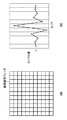
上述の通り、画像回復フィルタは2次元画像に適用する場合、画素に対応するタップを有する2次元フィルタとして構成され、タップ数は撮像光学系の収差特性や要求される回復精度に応じて決定することができる。図2(a)は、例として、水平及び垂直方向に11タップを有する11×11タップの2次元フィルタで構成された画像回復フィルタを模式的に示している。図2(a)では各タップの値(係数値)の記載を省略しているが、画像回復フィルタの1水平ラインのタップ係数の分布例を図2(b)に示す。画像回復フィルタのタップの値(係数値)の分布が、撮像光学系の収差によって空間的な広がりを持つ点像分布関数を、理想的には元の1点に戻す(回折の影響を無視した場合)役割を果たしている。 As described above, when applied to a two-dimensional image, the image restoration filter is configured as a two-dimensional filter having taps corresponding to pixels, and the number of taps is determined according to the aberration characteristics of the imaging optical system and the required restoration accuracy. be able to. FIG. 2A schematically shows, as an example, an image restoration filter constituted by an 11 × 11 tap two-dimensional filter having 11 taps in the horizontal and vertical directions. In FIG. 2A, the description of the value (coefficient value) of each tap is omitted, but FIG. 2B shows an example of tap coefficient distribution of one horizontal line of the image restoration filter. The point spread function, whose distribution of the tap values (coefficient values) of the image restoration filter has a spatial spread due to the aberration of the imaging optical system, is ideally restored to the original point (ignoring the effects of diffraction) If) play a role.
画像回復フィルタのタップ係数値は、画像回復処理の工程で実行される画素ごとのコンボリューション処理(畳み込み積分、積和)に用いられる。コンボリューション処理では、処理対象の画素の信号値に画像回復処理を適用するために、処理対象の画素を画像回復フィルタの中心タップと一致させる。そして、画像回復フィルタの各タップ位置において、対応する画素信号値とタップ係数値との積を求め、積の総和で処理対象の画素の信号値を置き換える。 The tap coefficient value of the image restoration filter is used for the convolution process (convolution integration, product sum) for each pixel executed in the image restoration process. In the convolution process, in order to apply the image restoration process to the signal value of the pixel to be processed, the pixel to be processed is matched with the center tap of the image restoration filter. Then, the product of the corresponding pixel signal value and the tap coefficient value is obtained at each tap position of the image restoration filter, and the signal value of the pixel to be processed is replaced with the sum of the products.
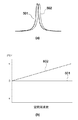
画像回復処理の実空間と周波数空間での特性を図3を用いて説明する。図3において、(a)は画像回復処理前の点像分布関数を、(b)は回復後の点像分布関数をそれぞれ示している。また、図3(c)の401は画像回復処理前のMTF、402は画像回復処理後のMTFを示し、図3(d)の403は画像回復処理前のPTF、404は画像回復処理後のPTFを示している。図3(a)からわかるように、画像回復処理前の点像分布関数は非対称な広がりを有し、この非対称性により、対応するPTFは零ではない値を有する(図3(d)403)。画像回復処理は、図3(c)の402に示すようにMTFを増幅し、図3(d)の404に示すようにPTFを零に補正するため、画像回復処理後の点像分布関数は図3(b)に示すように対称で先鋭になる。 The characteristics of the image restoration processing in the real space and the frequency space will be described with reference to FIG. 3A shows a point spread function before image restoration processing, and FIG. 3B shows a point spread function after restoration. In FIG. 3C, 401 indicates an MTF before the image recovery process, 402 indicates an MTF after the image recovery process, 403 in FIG. 3D indicates a PTF before the image recovery process, and 404 indicates after the image recovery process. PTF is shown. As can be seen from FIG. 3A, the point spread function before the image restoration processing has an asymmetric spread, and due to this asymmetry, the corresponding PTF has a non-zero value (FIG. 3D 403). . Since the image restoration process amplifies the MTF as indicated by 402 in FIG. 3C and corrects the PTF to zero as indicated by 404 in FIG. 3D, the point spread function after the image restoration process is As shown in FIG. 3B, it becomes symmetrical and sharp.
画像回復フィルタは、撮像光学系の光学伝達関数の逆関数(1/H)に基づいて設計した関数を逆フーリエ変換して得ることができる。画像回復フィルタには上述のウィナーフィルタを用いることができるが、他のフィルタを用いてもよい。ウィナーフィルタを用いる場合、光学伝達関数の逆関数を逆フーリエ変換することで、コンボリューション処理に用いる実空間の画像回復フィルタを作成することができる。 The image restoration filter can be obtained by inverse Fourier transform of a function designed based on the inverse function (1 / H) of the optical transfer function of the imaging optical system. As the image restoration filter, the above-described Wiener filter can be used, but other filters may be used. When the Wiener filter is used, a real space image restoration filter used for the convolution process can be created by performing an inverse Fourier transform on the inverse function of the optical transfer function.
次に、倍率色収差を考慮した画像回復フィルタの生成について説明する。図4(a)の502は、501の結像位置を基準として平行移動した位置に同形状の点像分布関数として結像した2つの色成分を表している。このときのPTFを図4(b)に示す。図4(b)の601、602は図4(a)の501、502と対応しており、602は位相が傾きをもった直線となっている。画像回復フィルタは、このような直線的なPTFも図3(d)の403のような非直線のPTFも、もととなる光学伝達関数に含まれているため図4(b)の601のように補正することができる。 Next, generation of an image restoration filter taking magnification chromatic aberration into consideration will be described. Reference numeral 502 in FIG. 4A represents two color components imaged as a point spread function having the same shape at a position translated from the imaging position 501 as a reference. The PTF at this time is shown in FIG. 601 and 602 in FIG. 4B correspond to 501 and 502 in FIG. 4A, and 602 is a straight line whose phase is inclined. The image restoration filter includes both such a linear PTF and a non-linear PTF such as 403 in FIG. 3D in the original optical transfer function. Can be corrected as follows.
また、予めPTFから直線成分を除去した光学伝達関数をもとに画像回復フィルタを生成することで、平行移動としての倍率色収差の成分を補正しない画像回復フィルタを生成することができる。一方、実空間で倍率色収差成分を除去する場合、図4(a)の502を501の位置に平行移動して差異を低減した点像分布関数を生成し、フーリエ変換することで、同様に倍率色収差の成分を除去した光学伝達関数を生成することができる。実際には501と502の点像分布関数の形状は異なるため、例えば重心を一致させる方法や501と502の差分の二乗平均を最小化するなどして両者を位置合わせすることができる。この光学伝達関数をもとに画像回復フィルタを生成することで、平行移動としての倍率色収差の成分を補正しない画像回復フィルタを生成することができる。 Further, by generating the image restoration filter based on the optical transfer function obtained by removing the linear component from the PTF in advance, it is possible to generate an image restoration filter that does not correct the lateral chromatic aberration component as the parallel movement. On the other hand, when removing the lateral chromatic aberration component in real space, a point spread function in which the difference is reduced by translating 502 in FIG. An optical transfer function from which the chromatic aberration component is removed can be generated. Actually, since the shape of the point spread function of 501 and 502 is different, both can be aligned by, for example, a method of matching the centroids or minimizing the root mean square of the difference between 501 and 502. By generating an image restoration filter based on this optical transfer function, an image restoration filter that does not correct the component of lateral chromatic aberration as a translation can be generated.
倍率色収差の成分を補正しない画像回復フィルタを適用することで、倍率色収差を画像回復処理と独立して処理することが可能になる。つまり、色成分ごとの非対称収差の補正および先鋭化と、倍率色収差の平行移動の成分である色ズレの補正とを分離して処理することが可能になる。 By applying an image restoration filter that does not correct the lateral chromatic aberration component, it is possible to process lateral chromatic aberration independently of the image restoration process. That is, the correction and sharpening of the asymmetric aberration for each color component and the correction of the color misregistration that is the component of the parallel movement of the magnification chromatic aberration can be processed separately.
なお、光学伝達関数は同一の撮像状態(ズーム位置や絞りの開口径)であっても撮像光学系の像高(画像の位置)に応じて変化するので、画像回復フィルタは像高に応じて変更して使用することが望ましい。
以上が、画像回復処理の概要である。
Since the optical transfer function changes according to the image height (image position) of the image pickup optical system even in the same image pickup state (zoom position or aperture diameter of the stop), the image restoration filter corresponds to the image height. It is desirable to change and use it.
The above is the outline of the image restoration process.
(倍率色収差の検出と補正)
倍率色収差の補正量は、上述のようにPTFの直線成分や点像分布関数の形状など、撮像光学系の設計値から算出することができる。
(Detection and correction of lateral chromatic aberration)
The correction amount of the lateral chromatic aberration can be calculated from the design values of the imaging optical system such as the linear component of the PTF and the shape of the point spread function as described above.
しかし、撮像光学系の製造ばらつきや撮像時の光源分光の変動により倍率色収差の画像上での現れ方が変化する場合があり、このような変化に対応する方法として画像から倍率色収差を検出する方法がある。画像から倍率色収差を検出して補正する方法に関して図5を用いて説明する。後述するように、本実施形態に係る撮像装置(図1)においては、画像処理部104の有する画像回復処理部111が以下の処理を実行することができるが、ここでは一般的な手順として説明する。
However, there are cases in which the appearance of lateral chromatic aberration on an image changes due to manufacturing variations in the imaging optical system and fluctuations in the light source spectrum at the time of imaging. A method for detecting lateral chromatic aberration from an image as a method for dealing with such a change. There is. A method for detecting and correcting lateral chromatic aberration from an image will be described with reference to FIG. As will be described later, in the imaging apparatus according to the present embodiment (FIG. 1), the image
まず、S201で撮像画像を入力画像として取得する。
次に、S202では、倍率色収差による色ズレが顕著に現れるエッジ部分を画像から検出する。エッジの検出にはY(輝度)プレーンを使用する。光学中心からの動径方向に大きく画素値の変化するエッジに限定して検出することにより、精度の高い色ズレ量取得が可能になる。また、Yプレーンにおいて、倍率色収差による色ズレはにじみとなって現れるので、画素値の単調増加もしくは単調減少が複数画素連続するような、ある程度幅のあるエッジを検出するのが良い。
First, in S201, a captured image is acquired as an input image.
Next, in S202, an edge portion in which a color shift due to lateral chromatic aberration appears noticeably is detected from the image. A Y (luminance) plane is used for edge detection. By detecting only an edge where the pixel value changes greatly in the radial direction from the optical center, it is possible to obtain a highly accurate color misregistration amount. Further, since the color shift due to the chromatic aberration of magnification appears on the Y plane, it is preferable to detect an edge having a certain width such that the pixel value monotonously increases or decreases continuously.
次に、S203では、S202で検出された各エッジにおいて色ズレ量を取得する。ここで扱う色ズレの方向は、光学中心と各エッジの位置関係により上/下方向、左/右方向、右斜め上/左斜め下方向、左斜め上/右斜め下方向の何れかを適用することで処理の簡略化を図る。各エッジにおける色ズレ量の取得には、色成分間の相関を用いる。例えば、色成分間の差分絶対値の和を判定して色ズレ量を取得することができる。Gプレーンに対しRプレーン(もしくはBプレーン)を色ズレ方向に移動させながら、検出されたエッジ付近の画素において、色成分間の差分絶対値和が最小となる場所を探索する。ここで検出された差分絶対値和が最小となった位置と、移動前の位置とから、Gプレーンに対するRプレーン(もしくはBプレーン)の色ズレ量を取得することができる。 Next, in S203, a color misregistration amount is acquired at each edge detected in S202. Depending on the positional relationship between the optical center and each edge, the color misregistration handled here can be any of up / down, left / right, right up / down left, left up / down right This simplifies the process. The correlation between the color components is used to obtain the color misregistration amount at each edge. For example, the amount of color misregistration can be acquired by determining the sum of absolute differences between color components. While moving the R plane (or B plane) with respect to the G plane in the direction of color misregistration, a search is made for a location where the sum of absolute differences between color components is minimized in pixels near the detected edge. The color shift amount of the R plane (or B plane) with respect to the G plane can be acquired from the position where the sum of absolute differences detected here is minimized and the position before the movement.
色ズレ量は、Gプレーンに対しRプレーン(もしくはBプレーン)が光学中心方向へずれている場合に負の値とし、Gプレーンに対しRプレーン(もしくはBプレーン)が光学中心とは逆方向へずれている場合に正の値とする。 The amount of color misregistration is a negative value when the R plane (or B plane) is displaced toward the optical center with respect to the G plane, and the R plane (or B plane) is opposite to the optical center with respect to the G plane. A positive value is assumed when there is a deviation.
S204では、S202で検出された各エッジの像高と、S203で取得した各エッジの色ズレ量から、像高と色ズレの関係を求めることで補正データを作成する。
ここでいう像高とは、光学中心に相当する画素(以降、単に光学中心という)からの距離である。
In S204, correction data is created by obtaining the relationship between the image height and the color shift from the image height of each edge detected in S202 and the color shift amount of each edge acquired in S203.
The image height here is a distance from a pixel corresponding to the optical center (hereinafter simply referred to as the optical center).
以下、補正データの作成手順について具体的に説明する。
(1)S202で検出されたエッジの像高をL、S203で取得された色ズレ量をDとした場合、下記のように像高に対する色ズレ率Mを求める。
M=D/L ・・・(式9)
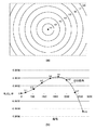
(2)図6(a)に示すように画像を像高に応じた複数の領域(ここではh1〜h8)に分割し、エッジが属する領域を選別する。
(3)画像内で検出された各エッジについて(1)(2)を行い、像高に応じて分割した領域ごとに色ズレ率Mを集計し、各領域での色ズレ率Mの平均値を各領域の色ズレ率として求める。
(4)図6(b)に示すように、像高と色ズレ率とから、像高lと色ズレ率Mとの関係を表す高次の多項近似式F(l)を算出し、これを補正データとする。図6(b)は以下の式10のように3次の多項式により補正データを算出した例である。なお式10においてa、b、cは係数を示している。
M=F(l)=al3 +bl2 +cl ・・・(式10)
The correction data creation procedure will be specifically described below.
(1) When the image height of the edge detected in S202 is L and the color shift amount acquired in S203 is D, the color shift rate M with respect to the image height is obtained as follows.
M = D / L (Formula 9)
(2) As shown in FIG. 6A, the image is divided into a plurality of regions (here, h1 to h8) according to the image height, and the region to which the edge belongs is selected.
(3) Perform (1) and (2) for each edge detected in the image, total the color misregistration ratio M for each area divided according to the image height, and average the color misregistration ratio M in each area Is obtained as the color misregistration ratio of each region.
(4) As shown in FIG. 6 (b), a higher-order polynomial approximate expression F (l) representing the relationship between the image height l and the color shift rate M is calculated from the image height and the color shift rate, Is the correction data. FIG. 6B shows an example in which correction data is calculated by a third-order polynomial as shown in Equation 10 below. In Equation 10, a, b, and c indicate coefficients.
M = F (l) = al 3 + bl 2 + cl (Equation 10)
なお、エッジの検出と色ズレ量取得は、画像内の全エッジに対して行っても良い。しかし、像高に応じて分割した各領域で、ある閾値以上の数の色ズレ率が集計された段階でエッジ検出と色ズレ量取得を終了するなど、信頼度を保ちながら処理の効率化を図ることもできる。 Note that edge detection and color shift amount acquisition may be performed for all edges in the image. However, in each area divided according to the image height, edge detection and color shift amount acquisition are completed when the number of color shift ratios equal to or greater than a certain threshold is tabulated, improving processing efficiency while maintaining reliability. You can also plan.
また、像高に応じて分割した複数の領域のうち、該当するエッジが見つかった領域のみを高次の多項近似式算出に使用することで、該当するエッジが見つからない領域があった場合でも補正データの作成が可能となる。 Moreover, even if there is a region where the corresponding edge is not found by using only the region where the corresponding edge is found among the multiple regions divided according to the image height, it is used for calculating the higher-order polynomial approximation. Data can be created.
次に、S205では、S204で作成された補正データを使用して色ズレを補正する。補正は対象色成分の画素位置をシフトすることで行い、具体的には例えば以下に示す方法で補正することができる。 In step S205, the color misregistration is corrected using the correction data created in step S204. The correction is performed by shifting the pixel position of the target color component. Specifically, for example, the correction can be performed by the following method.
まず、補正したいプレーン(Rプレーン、Bプレーン)の画素(X,Y)において、画素(X,Y)の像高Lと、補正データとから、画素(X,Y)における色ズレ率Mを求める。なお、光学中心に対応する画素が(0,0)の座標系とする。
M=F(L) ・・・(式11)
First, in the pixel (X, Y) of the plane (R plane, B plane) to be corrected, the color misregistration rate M in the pixel (X, Y) is calculated from the image height L of the pixel (X, Y) and the correction data. Ask. It is assumed that the pixel corresponding to the optical center is a coordinate system of (0, 0).
M = F (L) (Formula 11)
次に色ズレ補正により生成する画素の座標(X1,Y1)を求める。
X1=M×X ・・・(式12)
Y1=M×Y ・・・(式13)
Next, the coordinates (X1, Y1) of the pixel generated by the color misregistration correction are obtained.
X1 = M × X (Formula 12)
Y1 = M × Y (Formula 13)
補正したいプレーンにおいて上記座標(X1,Y1)に相当する画素値を、一般的な補間処理により生成し、画素(X,Y)の画素値とする。これらを全画素について行うことで、色ズレ補正を行う。
以上が、画像から倍率色収差補正データを作成し、補正するまでの処理概要である。
A pixel value corresponding to the coordinates (X1, Y1) in the plane to be corrected is generated by a general interpolation process, and is set as the pixel value of the pixel (X, Y). By performing these operations for all pixels, color misregistration correction is performed.
The above is the outline of the process from creating and correcting magnification chromatic aberration correction data from an image.
(撮像装置の構成)
図1は、本発明の実施形態にかかる画像処理装置の一例としての撮像装置の構成例を示すブロック図である。本実施形態では撮像光学系および撮像素子を有する撮像装置に本発明を適用した例を説明するが、本発明において撮像光学系や撮像素子といった撮像画像を生成するための構成要素は必須でない。
(Configuration of imaging device)
FIG. 1 is a block diagram illustrating a configuration example of an imaging apparatus as an example of an image processing apparatus according to an embodiment of the present invention. In this embodiment, an example in which the present invention is applied to an imaging apparatus having an imaging optical system and an imaging element will be described. However, in the present invention, components for generating a captured image such as an imaging optical system and an imaging element are not essential.
不図示の被写体の光学像を撮像光学系101で撮像素子102に結像する。撮像素子102で結像光が電気信号に変換され、A/Dコンバータ103でデジタル信号に変換されて、画像処理部104に入力される。画像処理部104は画像回復処理部111と、画像回復処理以外の画像処理を行う、他の画像処理部112から構成される。画像回復処理部111は、まず、状態検知部107から撮像装置の撮像状態の情報を得る。状態検知部107は撮像装置の撮像状態の情報をシステムコントローラ110から直接得ても良いし、例えば撮像光学系101に関する撮像状態の情報は撮像光学系制御部106から得てもよい。
An optical image of a subject (not shown) is formed on the
次に画像回復処理部111は、撮像状態に応じた画像回復フィルタを例えば記憶部108から選択し、画像回復処理部111は画像処理部104に入力された画像に対して倍率色収差補正処理および画像回復フィルタ適用処理を行う。画像回復処理の詳細については後述する。記憶部108で保持するデータは画像回復フィルタではなく、画像回復フィルタを生成するために必要な情報(例えば点像分布関数や光学伝達関数に関する情報)でもよい。この場合、画像回復処理部111は撮像状態に応じた点像分布関数又は光学伝達関数に関する情報を記憶部108から選択して撮像状態に応じた画像回復フィルタを生成し、この画像回復フィルタを用いて画像回復処理を行う。また、他の画像処理部112は画像回復処理後の画像に対し、ガンマ補正やカラーバランス調整など、所定の画像処理を行ないJPEG等の画像ファイルを生成する。
Next, the image
画像処理部104で処理された出力画像は、システムコントローラ110が画像記録媒体109に所定のフォーマットで保存する。また、表示部105には、画像回復処理後の画像に表示用の所定の処理を行った画像を表示しても良いし、画像回復処理を行わない、又は簡易的な回復処理を行った画像を表示しても良い。
The output image processed by the
一連の制御はシステムコントローラ110で行われ、撮像光学系101の機械的な駆動(絞り101a、フォーカスレンズ101b、光学ズームの駆動など)はシステムコントローラ110の指示により撮像光学系制御部106で行う。システムコントローラ110は例えばCPUやMPUのようなプログラマブルなコントローラであり、記憶部108に記憶されたプログラムを実行することで撮像装置の全体的な動作を実現する。なお、画像処理部104はハードウェアで実現してもよいが、少なくとも一部をシステムコントローラ110がソフトウェア的に実現することも可能である。
A series of control is performed by the
絞り101aは、Fナンバーの撮像状態設定として開口径が制御される。フォーカスレンズ101bは、被写体距離に応じてピント調整を行うために不図示のオートフォーカス(AF)機構や手動のマニュアルフォーカス機構によりレンズの位置が制御される。撮像光学系101にはローパスフィルタや赤外線カットフィルタ等の光学素子を入れても構わない。ただし、ローパスフィルタ等の光学伝達関数の特性に影響を与える素子を用いる場合には、画像回復フィルタを作成する時点でその光学素子による光学伝達関数の変化を考慮する。赤外カットフィルタにおいても、分光波長の点像分布関数の積分値であるRGBチャンネルの各点像分布関数、特にRチャンネルの点像分布関数に影響するため、画像回復フィルタを作成する時点で赤外カットフィルタによる点像分布関数の変化を考慮する。
また、撮像光学系101は撮像装置の一部として図示しているが、レンズ交換式カメラのような交換可能な構成であっても良い。
The aperture of the diaphragm 101a is controlled as an F number imaging state setting. The
Further, although the imaging
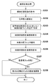
図7に画像回復処理部111での画像回復処理を説明するためのフローチャートを示す。
S301で画像回復処理部111は、状態検知部107から実際の撮像状態の情報を取得する。撮像状態とは、例えばズーム位置、絞り径、被写体距離等の撮像条件である。なお、これら撮像状態の情報は、画像ファイルのヘッダ部分などに書き込まれていることが多く、撮像済みの画像に対して画像回復処理を行う場合には、画像ファイルから取得してもよい。
FIG. 7 is a flowchart for explaining the image restoration processing in the image
In step S <b> 301, the image
S302で第1の倍率色収差補正手段としての画像回復処理部111は、倍率色収差の補正を行う。ここで行う倍率色収差の補正は上述の通り画素位置をシフトすることによって行うものであり、光学系の諸収差を補正する画像回復フィルタは適用しない。倍率色収差の補正量は、撮像光学系の設計値から算出したものを使用してもよいし、上述したように画像から倍率色収差を検出して補正量を決定してもよい。
In step S302, the image
S303で画像回復処理部111は、撮像条件に適した画像回復フィルタを選択する。このとき、選択された画像回復フィルタを必要に応じて補正しても構わない。これは、予め記憶部108に用意しておく画像回復フィルタのデータ数を低減するために、離散的な撮像状態のデータを用意しておいて、画像回復処理を実行する際に、実際の撮像状態に応じて画像回復フィルタを補正することである。また、画像回復フィルタの選択ではなく、画像回復フィルタを生成するために必要な光学伝達関数に関する情報から、撮像状態に応じた画像回復フィルタを生成してもよい。
In step S303, the image
また、本実施形態で用いる画像回復フィルタは、倍率色収差補正のための平行移動成分が除去されている。つまり、画像回復フィルタは倍率色収差補正成分を含んでおらず、収差の非対称性および広がりを補正して画像の先鋭化を行うが、倍率色収差の平行移動成分に関しては補正しない。上述の通り、このような画像回復フィルタを用いることにより、倍率色収差を画像回復処理と独立して処理することが可能になる。つまり、色成分ごとの非対称収差の補正および先鋭化と、倍率色収差の平行移動の成分である色ズレの補正とを分離して処理することが可能になる。 In addition, the image restoration filter used in the present embodiment is free from the translational component for correcting the lateral chromatic aberration. That is, the image restoration filter does not include the magnification chromatic aberration correction component, and corrects the asymmetry and spread of the aberration to sharpen the image, but does not correct the translation component of the magnification chromatic aberration. As described above, by using such an image restoration filter, it is possible to process lateral chromatic aberration independently of the image restoration process. That is, the correction and sharpening of the asymmetric aberration for each color component and the correction of the color misregistration that is the component of the parallel movement of the magnification chromatic aberration can be processed separately.
S304で第1の取得手段としての画像回復処理部111は、S302によって倍率色収差が補正された画像の色に関する特徴量の一例として、各画素における色差情報を取得する。ここでは、入力画像はRGB成分から構成され、色差を基準色Gに対する信号値の差分と定義する。従って、色差は以下の式により計算される。ここで、R1、G1、B1は、画像回復処理前のRGBの各信号値、(x,y)は画像上の座標値、C1r、C1bは、以下の式で定義されるR成分、B成分のG成分に対する色差である。
C1r(x,y)=R1(x,y)− G1(x,y) ・・・(式14)
C1b(x,y)=B1(x,y)− G1(x,y) ・・・(式15)
In S304, the image
C1r (x, y) = R1 (x, y) −G1 (x, y) (Expression 14)
C1b (x, y) = B1 (x, y) −G1 (x, y) (Equation 15)
なお、ここで、入力画像が例えばベイヤ配列の原色カラーフィルタを持つ撮像素子によって撮像された所謂RAW画像である場合、各画素はR,G,B成分のうち1つの値しか有していない。そのため、R画素又はB画素におけるG成分の値をG画素の値を適応補間して生成することにより、C1r及びC1bを求める。
一方、既に色補間処理済みで、各画素がRGB成分の値を有している場合には、各画素においてC1r及びC1bを求める。また、各画素がRGBの成分の値を有している場合には、各画素においてRGBの成分の値からY(輝度)の成分の値を求め、R成分、B成分の輝度成分に対する色差をC1r及びC1bとして求めるようにしてもよい。
Here, when the input image is a so-called RAW image captured by an image sensor having a primary color filter with a Bayer array, for example, each pixel has only one value of R, G, and B components. Therefore, C1r and C1b are obtained by generating the G component value in the R pixel or B pixel by adaptively interpolating the G pixel value.
On the other hand, when color interpolation processing has already been performed and each pixel has a RGB component value, C1r and C1b are obtained for each pixel. Further, when each pixel has RGB component values, the Y (luminance) component value is obtained from the RGB component values in each pixel, and the color difference between the R component and B component luminance components is calculated. You may make it obtain | require as C1r and C1b.
次にS305で画像回復処理部111は、S303で選択もしくは生成した画像回復フィルタを用いて、入力画像の各画素に対して上述したコンボリューション処理を行う。これにより、撮像光学系101の収差による点像分布関数の非対称性を補正し、画像のぼけ成分を除去もしくは低減することができる。
In step S305, the image
次のS306で第2の取得手段としての画像回復処理部111は、S305での画像回復処理後の画像の色に関する特徴量の一例として、各画素についてS304と同様に色差情報を取得する。ここで、R2、G2、B2は、画像回復処理後のRGBの各信号値、(x,y)は画像上の座標値、C2r、C2bは、以下の式で定義されるR成分、B成分のG成分に対する色差である。
C2r(x,y)=R2(x,y)− G2(x,y) ・・・(式16)
C2b(x,y)=B2(x,y)− G2(x,y) ・・・(式17)
In the next step S306, the image
C2r (x, y) = R2 (x, y) −G2 (x, y) (Expression 16)
C2b (x, y) = B2 (x, y) −G2 (x, y) (Expression 17)
なお、ここでも、C1r及びC1bを求める場合と同様、入力画像が色補間前のRAW画像である場合、R画素又はB画素におけるG成分の値をG画素の値を適応補間して生成することにより、C2r及びC2bを求める。
一方、既に色補間処理済みで、各画素がRGB成分の値を有している場合には、各画素においてC2r及びC2bを求める。
Here, as in the case of obtaining C1r and C1b, when the input image is a RAW image before color interpolation, the value of the G component in the R pixel or B pixel is generated by adaptively interpolating the value of the G pixel. To obtain C2r and C2b.
On the other hand, when color interpolation processing has already been performed and each pixel has a RGB component value, C2r and C2b are obtained for each pixel.
次にS307で画素値補正手段としての画像回復処理部111は、S304とS306で取得した、画像回復処理前後の各画素の色差情報C1r、C1b、C2r、C2bに基づき、色付き抑制のための画素値調整が必要か否かを決定する。この決定は、以下に示すように、色差が増大しているか否か、色差の符号が反転しているか否かに基づいて行うことができる。
Next, in step S307, the image
画像回復処理部111は、RGBの画素のうちR画素とB画素(又は、各画素におけるR成分とB成分)に対してそれぞれ以下の判定を行い、いずれかを満たす場合はその色成分の画素に対し、色付き抑制のための画素値調整が必要と決定する。
・Rに対する判定
判定条件1:
C1r(x,y)とC2r(x,y)が同符号、且つ|C1r(x,y)| < |C2r(x,y)|
判定条件2:
C1r(x,y)とC2r(x,y)が異符号
・Bに対する判定
判定条件1:
C1b(x,y)とC2b(x,y)が同符号、且つ|C1b(x,y)| < |C2b(x,y)|
判定条件2:
C1b(x,y)とC2b(x,y)が異符号
The image
-Judgment criteria for R 1:
C1r (x, y) and C2r (x, y) have the same sign, and | C1r (x, y) | <| C2r (x, y) |
Judgment condition 2:
C1r (x, y) and C2r (x, y) are different codes / B
C1b (x, y) and C2b (x, y) is the same sign, and | C1 b (x, y) | <| C2 b (x, y) |
Judgment condition 2:
C1b (x, y) and C2b (x, y) are different signs
この判定結果により、画素値調整が必要と決定された画素について、画素値補正手段としての画像回復処理部111はS308において色付き抑制のための画素値調整を適用する。画素値調整は例えば以下に示すように、色差が増大した場合は画像回復前の色差を使用し、色差の符号が反転した場合は色差を0とするものであってよい。
・Rに対する画素値調整
判定条件1を満たす場合(色差増大);
R2(x,y)= G2(x,y)+ C1r(x,y) ・・・(式18)
判定条件2を満たす場合(色差反転):
R2(x,y)= G2(x,y) ・・・(式19)
・Bに対する画素値調整
判定条件1を満たす場合(色差増大):
B2(x,y)= G2(x,y)+ C1b(x,y) ・・・(式20)
判定条件2を満たす場合(色差反転):
B2(x,y)= G2(x,y) ・・・(式21)
Based on the determination result, the image
When the pixel value
R2 (x, y) = G2 (x, y) + C1r (x, y) (Equation 18)
When judgment condition 2 is satisfied (color difference inversion):
R2 (x, y) = G2 (x, y) (Equation 19)
When the pixel value
B2 (x, y) = G2 (x, y) + C1 b (x, y) (Equation 20)
When judgment condition 2 is satisfied (color difference inversion):
B2 (x, y) = G2 (x, y) (Expression 21)
このように、図7のフローチャートに従った処理により、画像処理部104(画像回復処理部111)における画像回復処理が実行される。なお、撮像光学系101の光学伝達関数は1つの撮像状態においても撮像光学系の画角(像高)に応じて変化するので、ここで説明した画像回復処理を、像高に応じたて分割した領域(図6のh1〜h8)ごとに変更して行うことが望ましい。具体的には、画像回復フィルタを画像上にコンボリューション処理をしながら走査させ、領域毎にフィルタを順次変更すれば良い。すなわちS303の処理を各対象画素に対して実行する。
As described above, the image recovery processing in the image processing unit 104 (image recovery processing unit 111) is executed by the processing according to the flowchart of FIG. Since the optical transfer function of the imaging
なお、本実施形態では理解及び説明を容易にするため、画像回復フィルタの適用=画像回復処理として説明したが、画像回復処理の一部として、他の補正処理、例えば歪曲補正処理や周辺光量補正処理やノイズ低減処理等を含めてもよい。 In this embodiment, in order to facilitate understanding and explanation, application of the image restoration filter is described as image restoration processing. However, as part of the image restoration processing, other correction processing such as distortion correction processing and peripheral light amount correction is performed. Processing, noise reduction processing, and the like may be included.
ここで、S302、S304、S305、S306、S308で行なわれる倍率色収差補正、画像回復処理前後の色差情報取得、画像回復フィルタ適用の作用および効果の例を図9及び図10を用いて説明する。 Here, examples of operations and effects of correcting the chromatic aberration of magnification performed in S302, S304, S305, S306, and S308, obtaining color difference information before and after the image restoration process, and applying the image restoration filter will be described with reference to FIGS.
図9(a)〜(c)は、図8に示したような、周辺部に点光源が存在する被写界を撮像した入力における、点光源とその近傍の水平方向における画素値の例を示す模式図である。図9(a)〜(c)はいずれも上段にR成分とG成分の画素値を、下段には上段で示したR成分とG成分の差分、つまり色差を示している。 FIGS. 9A to 9C show examples of the pixel values in the horizontal direction of the point light source and the vicinity thereof in the input obtained by imaging the object scene where the point light source exists in the periphery as shown in FIG. It is a schematic diagram shown. 9A to 9C show the pixel values of the R component and the G component in the upper stage, and the difference between the R component and the G component shown in the upper stage, that is, the color difference in the lower stage.
図9(b)は、非合焦時の状態を示している。合焦時の状態を示す図9(a)と比べると、倍率色収差による色ズレは同様に発生しているが、G成分、R成分ともにぼけ量が大きく、またG成分とR成分は同じぼけ方をしている。倍率色収差補正後はR成分とG成分の位置が揃い、G成分とR成分のぼけ方が同じであるため、この段階で色にじみは発生していない。画像回復フィルタ適用後は、G成分、R成分ともにぼけが低減されているが、G成分とR成分のぼけの残り方が異なるため、色にじみが発生している。この色にじみが本実施形態において抑制の対象となる色付きである。 FIG. 9B shows a state when the lens is out of focus. Compared to FIG. 9A showing the state at the time of focusing, color deviation due to chromatic aberration of magnification occurs in the same manner, but the blur amount is large for both the G component and the R component, and the G component and the R component are the same blur. I'm doing better. After correcting the lateral chromatic aberration, the positions of the R component and the G component are aligned, and the blurring of the G component and the R component is the same, so no color blur occurs at this stage. After application of the image restoration filter, the blur is reduced for both the G component and the R component, but color blurring occurs because the remaining blur of the G component and the R component is different. This color blur is colored which is the object of suppression in this embodiment.
図9(b)に対応する画像回復フィルタ適用前後の色差情報の関係を図10(b)に示す。画像回復フィルタの適用前である倍率色収差補正後の色差は全領域で0となっているが、画像回復フィルタ適用後はエッジ部分で色差が発生している。従って、S307における判定処理では色差増大により画素値調整が必要と決定され、S308で画像回復処理部111によって色付き抑制のための画素値調整が適用される。S308での画素値調整処理では、画像回復フィルタの適用前の色差である倍率色収差補正後の色差が使用されるため、画素値調整後の色差は全領域で0となり、色付きが適切に抑制された画像が得られる。
FIG. 10B shows the relationship between the color difference information before and after applying the image restoration filter corresponding to FIG. The color difference after correcting the chromatic aberration of magnification before application of the image restoration filter is 0 in all regions, but after the application of the image restoration filter, a color difference occurs at the edge portion. Accordingly, in the determination process in S307, it is determined that pixel value adjustment is necessary due to an increase in color difference, and in S308, pixel value adjustment for suppressing coloring is applied by the image
このように、本実施形態では、非合焦時部分に対する画像回復フィルタの適用によって発生する色付きを効果的に抑制することができる。図9(a)で示した合焦時と図9(b)で示した非合焦時のそれぞれで、画像回復フィルタ適用前後のG成分とR成分のぼけ方の違いについて図11を用いて説明する。図11(a)〜(d)は撮像光学系101のMTFと画像回復フィルタ適用後のMTFの空間周波数特性を示す模式図である。また、図11(e)は画像回復フィルタによるMTFの増減率(回復ゲイン)を示す模式図である。
Thus, in the present embodiment, it is possible to effectively suppress coloring that occurs due to the application of the image restoration filter to the out-of-focus portion. FIG. 11 shows the difference in blurring between the G component and the R component before and after the application of the image restoration filter in the in-focus state shown in FIG. 9A and in the out-of-focus state shown in FIG. 9B. explain. 11A to 11D are schematic diagrams illustrating the spatial frequency characteristics of the MTF of the imaging
図11(a)は合焦時の撮像光学系101のMTFであり、R成分はG成分よりも劣化している。従って図9(a)の入力画像ではG成分とR成分のぼけ方が異なり、点光源部分の画素値の変化はR成分の方がG成分よりも広がった状態になっている。
FIG. 11A shows the MTF of the imaging
図11(b)は合焦時の画像回復フィルタ適用後のMTFであり、G成分とR成分ともにMTFが適切に補正され、G成分とR成分は一致している。これは図11(a)のMTFに図11(e)に示す回復ゲインが乗算された結果である。画像回復フィルタは合焦物体に最適な画像回復処理が行なえるように設計されているため、合焦時は適切な画像回復処理がされる。従って図9(a)の画像回復フィルタ適用後ではG成分とR成分のぼけが適切に除去され、色にじみも除去されている。 FIG. 11B shows the MTF after applying the image restoration filter at the time of focusing. Both the G component and the R component are corrected appropriately, and the G component and the R component match. This is a result of multiplying the MTF of FIG. 11A by the recovery gain shown in FIG. Since the image restoration filter is designed so that an optimum image restoration process can be performed on the in-focus object, an appropriate image restoration process is performed at the time of focusing. Therefore, after applying the image restoration filter of FIG. 9A, the blur of the G component and the R component is appropriately removed, and the color blur is also removed.
一方、図11(c)は非合焦時の撮像光学系101のMTFであり、図11(a)の合焦時と比較するとG成分もR成分も劣化した状態で一致している。従って図9(b)の入力画像ではG成分とR成分のぼけ方が一致しているが図9(a)で示した合焦時よりぼけが大きくなっている状態である。
On the other hand, FIG. 11C shows the MTF of the imaging
図11(d)は非合焦時の画像回復フィルタ適用後のMTFであり、G成分とR成分ともにMTFが補正されているが、G成分はR成分よりも劣化した状態になっている。これは図11(c)のMTFに図11(e)に示す回復ゲインが乗算された結果である。画像回復フィルタは合焦物体に最適な画像回復処理が行なえるように設計されているため、非合焦時は期待した画像回復結果にならない場合がある。従って、図9(b)の画像回復フィルタ適用後ではG成分とR成分のぼけが低減しているが、G成分の方がR成分よりも広がった状態になっている。 FIG. 11D shows the MTF after application of the image restoration filter in the out-of-focus state. Both the G component and the R component are corrected for the MTF, but the G component is in a state of being deteriorated more than the R component. This is a result of multiplying the MTF of FIG. 11C by the recovery gain shown in FIG. Since the image restoration filter is designed so that an optimum image restoration process can be performed on the in-focus object, the expected image restoration result may not be obtained when the image is out of focus. Therefore, the blur of the G component and the R component is reduced after the application of the image restoration filter of FIG. 9B, but the G component is more spread than the R component.
本実施形態と異なり、画像回復フィルタに倍率色収差補正成分を含めた場合の例を図9(c)に示す。
図9(c)は、図9(b)と同様の非合焦時において、倍率色収差補正成分を含めた画像回復フィルタを適用した場合の例を示している。入力画像は図9(b)と同じであり、また倍率色収差補正を行わないが、画像回復フィルタで倍率色収差補正も同時に行うため、画像回復フィルタ適用後の画像も図9(b)と同じである。
Unlike this embodiment, FIG. 9C shows an example in which a magnification chromatic aberration correction component is included in the image restoration filter.
FIG. 9C shows an example in which an image restoration filter including a magnification chromatic aberration correction component is applied in the out-of-focus state similar to FIG. 9B. The input image is the same as in FIG. 9B, and the chromatic aberration of magnification is not corrected. However, since the chromatic aberration of magnification is also corrected by the image recovery filter, the image after application of the image recovery filter is the same as in FIG. is there.
画像回復フィルタ適用前後の色差情報の関係を図10(c)に示す。画像回復フィルタの適用前の入力画像の色差は色ズレにより左側のエッジ部分で正の値、右側のエッジ部分で負の値として存在する。また、画像回復フィルタ適用後は両エッジ部分で負の値の色差が発生している。従って、S307における判定処理では、左側のエッジ部では色差反転しているとの判定により画素値調整が必要と決定され、S308で色付き抑制のための画素値調整が行なわれるので色付きが抑制される。しかし、右側のエッジは色差の増大も反転もないことから、画素値調整は不要と決定され、S308での画素値調整は行われない。そのため、右側のエッジでは色付きが抑制されないまま画像回復処理結果として出力される。
このように、画像回復フィルタに倍率色収差補正成分を含めた場合には画像回復フィルタの適用によって生じた色付きが十分に抑制されず、画質が劣化する。
FIG. 10C shows the relationship between the color difference information before and after applying the image restoration filter. The color difference of the input image before application of the image restoration filter exists as a positive value at the left edge portion and as a negative value at the right edge portion due to color misregistration. Further, after application of the image restoration filter, a negative color difference occurs at both edge portions. Accordingly, in the determination process in S307, it is determined that the pixel value adjustment is necessary by determining that the color difference is inverted at the left edge portion, and the pixel value adjustment for suppressing coloring is performed in S308, so that coloring is suppressed. . However, since the right edge does not increase or invert the color difference, it is determined that the pixel value adjustment is unnecessary, and the pixel value adjustment in S308 is not performed. For this reason, the right edge is output as an image restoration processing result without being colored.
As described above, when a magnification chromatic aberration correction component is included in the image restoration filter, coloring caused by the application of the image restoration filter is not sufficiently suppressed, and the image quality is deteriorated.
以上説明したように、本実施形態によれば、撮像光学系の収差を補正するための画像回復フィルタとして、倍率色収差補正を行わない画像回復フィルタを用いるとともに、倍率色収差は画像回復フィルタを適用する前に、画像回復フィルタとは別の方法で補正する。そのため、実際の撮像状態での収差の状態と、画像回復フィルタが想定している収差の状態が異なるときに発生する、画像回復フィルタに起因する色付きを、倍率色収差に起因する色付きと分離して補正することが可能になり、色付きを効果的に抑制可能となる。 As described above, according to the present embodiment, an image restoration filter that does not perform magnification chromatic aberration correction is used as an image restoration filter for correcting aberrations of the imaging optical system, and an image restoration filter is applied to magnification chromatic aberration. Before, correction is performed by a method different from that for the image restoration filter. Therefore, the coloring caused by the image restoration filter, which occurs when the aberration state in the actual imaging state is different from the aberration state assumed by the image restoration filter, is separated from the coloring caused by the chromatic aberration of magnification. It becomes possible to correct, and coloring can be effectively suppressed.
つまり、倍率色収差の色ズレによる色付きと、ぼけの除去時に発生する色付きとを切り分けることができ、ぼけの除去時に発生する色付きのみを抑制することが可能になる。このように、本実施形態によれば、画像回復処理全体として色付きを抑えた画像回復処理が可能となる。 That is, it is possible to separate the coloring due to the color shift of the chromatic aberration of magnification and the coloring generated when removing the blur, and it is possible to suppress only the coloring generated when removing the blur. As described above, according to the present embodiment, it is possible to perform an image restoration process in which coloring is suppressed as the entire image restoration process.
(第2の実施形態)
次に、本発明の第2の実施形態について説明する。なお、本実施形態も第1の実施形態対と同様、図1に示した撮像装置に適用した場合について説明する。第1の実施形態とは画像処理部104(画像回復処理部111)における画像回復処理のみ異なるため、図12を用いて本実施形態における画像回復処理について説明する。
(Second Embodiment)
Next, a second embodiment of the present invention will be described. Note that, similarly to the first embodiment pair, the present embodiment will be described when applied to the imaging apparatus shown in FIG. Since only the image restoration process in the image processing unit 104 (image restoration processing unit 111) is different from the first embodiment, the image restoration process in the present embodiment will be described with reference to FIG.
なお、図12におけるS401からS405までの処理は、図7のS301からS305までの処理と同様であるため、説明は割愛する。本実施形態では、S405で画像回復フィルタを適用した後に、S406で画像から倍率色収差を検出して生成した補正量を使用した倍率色収差の補正を行うことを特徴とする。 Note that the processing from S401 to S405 in FIG. 12 is the same as the processing from S301 to S305 in FIG. The present embodiment is characterized in that, after applying the image restoration filter in S405, the magnification chromatic aberration is corrected using the correction amount generated by detecting the magnification chromatic aberration from the image in S406.
図13及び図14は、本実施形態においてS402、S404、S405、S406、S407、S408で行なわれる倍率色収差補正、画像回復処理前後の色差情報取得、画像回復フィルタ適用の作用及び効果の例を示す模式図である。 FIGS. 13 and 14 show examples of operations and effects of correcting the chromatic aberration of magnification performed in S402, S404, S405, S406, S407, and S408, obtaining color difference information before and after image restoration processing, and applying an image restoration filter in this embodiment. It is a schematic diagram.
図13(a)〜(d)は、図8に示したような、周辺部に点光源が存在する被写界を撮像した入力における、点光源とその近傍のメリジオナル方向(画像中心から放射方向)における画素値の例を示す模式図である。図13(a)〜(d)はいずれも上段にR成分とG成分の画素値を、下段には上段で示したR成分とG成分の差分、つまり色差を示している。図9とは着目している画素の方向が異なるため、非対称収差となり、左右のエッジでぼけ方が異なっている。 FIGS. 13A to 13D show a point light source and its meridional direction (radiation direction from the center of the image) in an input obtained by capturing an image of a scene in which a point light source exists in the periphery as shown in FIG. It is a schematic diagram which shows the example of the pixel value in). 13A to 13D show the pixel values of the R component and the G component in the upper stage, and the difference between the R component and the G component shown in the upper stage, that is, the color difference, in the lower stage. Since the pixel direction of interest is different from that in FIG. 9, the asymmetrical aberration occurs, and the left and right edges are blurred.
倍率色収差を補正しない画像回復フィルタを適用した後に、S406で画像から倍率色収差を検出して補正することの効果について図13(a)を用いて説明する。図13(a)は、合焦時の状態を示している。入力画像には倍率色収差によりG成分とR成分の色ズレが発生し、さらにG成分とR成分のぼけ方が異なっており、左右のエッジの収差が異なるためにぼけ方が異なっている。 The effect of detecting and correcting lateral chromatic aberration from an image in S406 after applying an image restoration filter that does not correct lateral chromatic aberration will be described with reference to FIG. FIG. 13A shows a state at the time of focusing. In the input image, a color shift between the G component and the R component occurs due to the chromatic aberration of magnification. Further, the blurring of the G component and the R component is different, and the blurring is different because the aberrations of the left and right edges are different.
画像回復フィルタ適用前に行うS402での倍率色収差補正の結果を、図13(a)の、”倍率色収差補正後1”で示している。S402の倍率色収差補正では、左右のエッジの収差の状態が異なったまま、色ズレができるだけ目立たないような倍率色収差補正を行う。倍率色収差の補正量は、撮像光学系101の設計値から算出したものを使用してもよいし、画像から倍率色収差を検出して補正量を決定してもよい。
The result of the magnification chromatic aberration correction in S402 performed before application of the image restoration filter is shown as “after magnification
画像回復フィルタの適用により、G成分、R成分のエッジは非対称収差が補正され且つ先鋭化されているが、G成分、R成分間の色ズレが残留している。この、残留している色ズレの原因は、撮像光学系101の製造上のばらつきや、光源分光の変動などにより、画像撮像時の収差の状態と、画像回復フィルタが対象としている収差の状態とが異なることが挙げられる。また、画像回復フィルタ適用前に行うS402での倍率色収差補正において、画像から倍率色収差を検出して補正量を決定する場合、非対称性の残留したエッジで倍率色収差量の検出を行っている。そのため、画像回復処理後のエッジの状態に適切な倍率色収差の補正量と異なる補正量が得られる場合があり、その場合には色ズレが残留する。
By applying the image restoration filter, the edges of the G component and the R component are corrected for asymmetrical aberrations and sharpened, but a color shift between the G component and the R component remains. The cause of the remaining color misregistration is due to variations in manufacturing of the imaging
本実施形態はこのような理由によって画像回復フィルタの適用後に残留する色ズレに対処する。S406において第2の倍率色収差補正手段としての画像回復処理部111は、画像回復フィルタ適用後の画像から倍率色収差を検出して補正を行う。S406での倍率色収差補正処理後の状態を図13(a)の倍率色収差補正後2で示している。倍率色収差補正後2では残留した色ズレが適切に補正された状態であり、入力画像に対してはエッジは非対称収差が補正され且つ先鋭化されG成分とR成分が一致することで色にじみも除去されている。
For this reason, the present embodiment deals with color misregistration remaining after application of the image restoration filter. In S406, the image
S407において画像回復処理部111は、S406での倍率色収差補正処理後の画像の色に関する特徴量の一例として、各画素についてS306と同様に色差情報を取得する。
次に行なわれるS408からS409の処理は、第1の実施形態で説明した図7のS307からS308の処理と同様であるため、説明は割愛する。
In step S407, the image
The process of S409 from S40 8 which is performed, since the S30 7 7 described in the first embodiment is similar to the processing in S308, description thereof is omitted.
図13(a)に示した合焦時に、S404、S407で取得された色差情報を図14(a)に示す。この場合、画像回復フィルタの適用前の”倍率色収差補正後1”での色差はエッジ部分で値を持っているが、画像回復フィルタの適用後の”倍率色収差補正後2”では全領域で0となっている。従って、S408における判定処理では、色付き抑制のための画素値調整は不要と判断され、倍率色収差補正後2の画像がそのまま画像回復処理結果となる。
FIG. 14A shows the color difference information acquired in S404 and S407 at the time of focusing shown in FIG. In this case, the color difference at “after magnification
図13(a)と同じ入力画像に対し、本実施形態と異なり画像回復フィルタ適用後にS406の倍率色収差補正を行なわない場合の例を図13(b)に示す。この場合、画像回復フィルタ適用後の色ズレが残留している状態でS407の色差情報取得処理が行われる。図14(b)に示すように、画像回復処理前後で左側のエッジでは色差の反転、右側のエッジでは色差の増大がそれぞれ発生しているため、いずれもS409で色付き抑制のための画素値調整が行なわれる。この場合の出力画像は図13(b)の”画素値調整後”の状態である。S409における色付き抑制処理によって色付きは抑制されているが、S406の倍率色収差補正を行なった場合の図12(a)と比べると、色付きが残留していることがわかる。このように、画像回復フィルタ適用後、色付き抑制処理の要否判定前の画像で倍率色収差を検出し、補正を行うことで、色付きをより適切に抑制することができる。 FIG. 13B shows an example in which the magnification chromatic aberration correction in S406 is not performed on the same input image as FIG. 13A after the image restoration filter is applied unlike the present embodiment. In this case, the color difference information acquisition process of S407 is performed in a state where the color shift after application of the image restoration filter remains. As shown in FIG. 14B, since the color difference is inverted at the left edge and the color difference is increased at the right edge before and after the image restoration process, the pixel value adjustment for suppressing coloring is performed in S409. Is done. The output image in this case is in the “after pixel value adjustment” state of FIG. Although coloring is suppressed by the coloring suppression processing in S409, it can be seen that coloring remains as compared with FIG. 12A when the magnification chromatic aberration correction of S406 is performed. Thus, coloring can be suppressed more appropriately by detecting magnification chromatic aberration in the image after applying the image restoration filter and before determining whether or not coloring suppression processing is necessary, and performing correction.
以上、本発明の第2の実施形態について説明した。このように、画像回復フィルタを適用した後に、画像から倍率色収差を検出して補正する場合でも本発明は有効である。 The second embodiment of the present invention has been described above. As described above, the present invention is effective even when the lateral chromatic aberration is detected and corrected from the image after the image restoration filter is applied.
図13(c)に、図13(a)に対応する非合焦時の状態を示す。入力画像には倍率色収差によりG成分とR成分の色ズレが発生し、さらにG成分とR成分のぼけ方は同じであるが、左右のエッジの収差が異なるために左右のエッジでぼけ方が異なっている状態である。S402で倍率色収差補正した後の”倍率色収差補正後1”では、R成分とG成分の位置が揃い、G成分とR成分のぼけ方が同じであるため、この段階で色にじみは発生していない。 FIG. 13C shows a non-focus state corresponding to FIG. In the input image, the G component and the R component are misaligned due to the chromatic aberration of magnification, and the blurring of the G component and the R component is the same, but the left and right edges are blurred due to different aberrations of the left and right edges. It is in a different state. In “1 after magnification chromatic aberration correction” after the magnification chromatic aberration correction in S402, the positions of the R component and the G component are aligned, and the blurring of the G component and the R component is the same. Absent.
画像回復フィルタ適用後は、G成分、R成分ともにぼけが低減されているが、G成分とR成分のぼけの残り方が異なるために色にじみが発生している。この色にじみは左右のエッジの状態が異なり、色ズレとして扱うことができる。S406において、画像回復フィルタ適用後の画像から倍率色収差を検出し、補正した結果を示す”倍率色収差補正後2”では、左右のエッジの色にじみ方が同じになっている。この場合の画像回復処理前後の色差情報の関係を図14(c)に示す。画像回復フィルタの適用前の”倍率色収差補正後1”での色差は全領域で0となっているが、画像回復フィルタの適用後の”倍率色収差補正後2”はエッジ部分で色差が発生している。従って、S408における判定処理では色付き抑制のための画素値調整が必要と判定され、S409で色付き抑制のための画素値調整が行なわれる。S409では、画像回復フィルタの適用前の”倍率色収差補正後1”の色差が使用されるため、画素値調整後の色差は全領域で0となり、色差が適切に抑制された画像が画像回復処理結果として得られる。
After application of the image restoration filter, the blur is reduced for both the G component and the R component, but color blur occurs because the remaining blur of the G component and the R component is different. This color blur has different left and right edge states and can be treated as a color shift. In S406, the chromatic aberration of magnification is detected from the image after the application of the image restoration filter and “after chromatic aberration of magnification correction 2” indicating the result of correction is applied, the left and right edges are smeared in the same way. FIG. 14C shows the relationship between color difference information before and after the image restoration process in this case. The color difference at “after correction of chromatic aberration of
本実施形態と異なり、画像回復フィルタに倍率色収差補正成分を含めた場合の例を図13(d)に示す。
図13(d)において、入力画像は図13(c)と同じである。S402での倍率色収差補正を行わずに画像回復フィルタで倍率色収差補正も同時に行うため、画像回復フィルタ適用後の画像と、画像回復フィルタ適用後の画像から倍率色収差を検出して補正した”倍率色収差補正後2”の画像は、図13(c)と同様である。この場合の画像回復処理前後の色差情報の関係を図14(d)に示す。左右のエッジとも一部で色差の反転があるため、S408における判定処理では色付き抑制のための画素値調整が必要と判定され、S409で色付き抑制のための画素値調整が行なわれる。この場合の出力画像は図13(d)の”画素値調整後”の状態である。色付き抑制処理によって色付きは抑制されているが、本実施形態による図13(c)と比べると色付きが残っていることが確認される。
Unlike this embodiment, FIG. 13D shows an example in which a magnification chromatic aberration correction component is included in the image restoration filter.
In FIG. 13 (d), the input image is the same as in FIG. 13 (c). Since the magnification chromatic aberration correction is also performed simultaneously with the image restoration filter without performing the magnification chromatic aberration correction in S402, the magnification chromatic aberration is detected and corrected from the image after application of the image restoration filter and the image after application of the image restoration filter. The corrected 2 ″ image is the same as in FIG. FIG. 14D shows the relationship between the color difference information before and after the image restoration process in this case. Since the left and right edges have some color difference inversions, it is determined that the pixel value adjustment for suppressing coloring is necessary in the determination processing in S408, and the pixel value adjustment for suppressing coloring is performed in S409. The output image in this case is in the “after pixel value adjustment” state of FIG. Although coloring is suppressed by the coloring suppression processing, it is confirmed that coloring remains compared to FIG. 13C according to the present embodiment.
以上説明したように、本実施形態によれば、倍率色収差を補正しない画像回復フィルタ適用後、色付き抑制のための画素値調整の有無を判定する前に、画像回復フィルタ適用後の画像から倍率色収差を検出して補正する。これにより、一層良好な色付き抑制効果を実現することが可能になる。 As described above, according to the present embodiment, after applying the image restoration filter that does not correct the lateral chromatic aberration, before determining whether or not to adjust the pixel value for suppressing coloring, the lateral chromatic aberration from the image after applying the image restoration filter. Is detected and corrected. Thereby, it becomes possible to realize a better coloring suppression effect.
(その他の実施形態)
上述の実施形態においては、画像回復処理前後における画像の色に関する特徴量として、色差を用いた場合を説明した。しかし、色差に限らず、画像回復フィルタの適用によって生じた色付きを補正するために用いることが可能な任意の色に関する特徴量を用いることができる。例えば、画像回復処理前後における画像にて、Gプレーンに対しRプレーン(もしくはBプレーン)をメリジオナル方向に移動させながら、Yプレーンで検出されたエッジ付近の画素において、色成分間の差分絶対値和が最小となる場所を探索する。ここで検出された差分絶対値和が最小となった位置と、移動前の位置とから、Gプレーンに対するRプレーン(もしくはBプレーン)の色ズレ方向と色ズレ量を取得し、この色ズレ方向と色ズレ量を色に関する特徴量とすることができる。画像回復処理前後における画像の色ズレ方向が反転していれば、色付き抑制のための画素値調整を行い、色ズレ方向が反転していなくとも画像回復処理後の色ズレ量ほうが大きいのであれば、色付き抑制のための画素値調整を行うようにすればよい。
(Other embodiments)
In the above-described embodiment, the case where the color difference is used as the feature amount related to the color of the image before and after the image restoration processing has been described. However, not only the color difference but also a feature amount related to an arbitrary color that can be used to correct coloring caused by application of the image restoration filter can be used. For example, in the image before and after the image restoration process, the difference absolute value sum between color components is detected in pixels near the edge detected in the Y plane while moving the R plane (or B plane) in the meridional direction with respect to the G plane. Search for a location where is minimal. The color shift direction and color shift amount of the R plane (or B plane) with respect to the G plane are acquired from the position where the sum of absolute differences detected here is the minimum and the position before the movement, and this color shift direction The amount of color misregistration can be used as a feature amount related to color. If the color misregistration direction of the image before and after the image restoration processing is reversed, the pixel value adjustment for suppressing coloring is performed, and if the amount of color misregistration after the image restoration processing is larger even if the color misregistration direction is not reversed Then, pixel value adjustment for suppressing coloring may be performed.
また、本発明は、以下の処理を実行することによっても実現される。即ち、上述した実施形態の機能を実現するソフトウェア(プログラム)を、ネットワーク又は各種記憶媒体を介してシステム或いは装置に供給し、そのシステム或いは装置のコンピュータ(またはCPUやMPU等)がプログラムを読み出して実行する処理である。 The present invention can also be realized by executing the following processing. That is, software (program) that realizes the functions of the above-described embodiments is supplied to a system or apparatus via a network or various storage media, and a computer (or CPU, MPU, or the like) of the system or apparatus reads the program. It is a process to be executed.
Claims (12)
前記画像に対して前記撮像光学系の倍率色収差の補正を行う第1の倍率色収差補正手段と、
前記倍率色収差が補正された画像について、色に関する特徴量を取得する第1の取得手段と、
前記撮像光学系の収差に基づいた画像回復フィルタを前記倍率色収差が補正された画像に適用する画像回復処理手段と、
前記画像回復フィルタが適用された画像に対し、前記色に関する特徴量を取得する第2の取得手段と、
前記第1の取得手段と前記第2の取得手段が取得した前記色に関する特徴量の変化に応じて、前記画像回復フィルタが適用された画像の画素値を補正する画素値補正手段とを有し、
前記画像回復フィルタは、倍率色収差の補正を行わないフィルタであることを特徴とする画像処理装置。 An image processing device for recovering deterioration in image quality due to aberration of an imaging optical system of the imaging device in an image captured by the imaging device,
First magnification chromatic aberration correction means for correcting magnification chromatic aberration of the imaging optical system for the image;
A first acquisition unit configured to acquire a color-related feature amount for an image in which the lateral chromatic aberration is corrected;
Image restoration processing means for applying an image restoration filter based on the aberration of the imaging optical system to the image in which the lateral chromatic aberration is corrected;
Second acquisition means for acquiring a feature amount related to the color for an image to which the image restoration filter is applied;
In accordance with a change in the characteristic quantity relating to the color of the first acquisition means and the second acquisition means has acquired, have a pixel value correcting means for correcting the pixel value of the image by the image restoration filter applied ,
The image restoration filter, the image processing apparatus according to claim filters der Rukoto is not corrected for chromatic aberration of magnification.
前記第2の取得手段が、前記第2の倍率色収差補正手段によって倍率色収差が補正された画像に対して前記色に関する特徴量を取得することを特徴とする請求項1乃至請求項3のいずれか1項に記載の画像処理装置。 Furthermore, it has a second magnification chromatic aberration correction means for detecting and correcting magnification chromatic aberration from the image to which the image restoration filter is applied,
Said second acquisition means, any of claims 1 to 3, characterized in that to obtain the feature quantity relating to said color to an image magnification chromatic aberration is corrected by said second magnification chromatic aberration correction unit The image processing apparatus according to item 1.
前記光学像を撮像する撮像素子と、
請求項1乃至請求項9のいずれか1項に記載の画像処理装置とを有することを特徴とする撮像装置。 An imaging optical system that forms an optical image of the subject;
An image sensor that captures the optical image;
Imaging apparatus characterized by comprising an image processing apparatus according to any one of claims 1 to 9.
前記画像処理装置の倍率色収差補正手段が、前記画像に対して前記撮像光学系の倍率色収差の補正を行う工程と、
前記画像処理装置の第1の取得手段が、前記倍率色収差が補正された画像について、色に関する特徴量を取得する第1の取得工程と、
前記画像処理装置の画像回復処理手段が、前記撮像光学系の収差に基づいた画像回復フィルタを前記倍率色収差が補正された画像に適用する工程と、
前記画像処理装置の第2の取得手段が、前記画像回復フィルタが適用された画像に対し、前記色に関する特徴量を取得する第2の取得工程と、
前記画像処理装置の前記第1の取得工程と前記第2の取得工程で取得された前記色に関する特徴量の変化に応じて、画素値補正手段が、前記画像回復フィルタが適用された画像の画素値を補正する工程とを有し、
前記画像回復フィルタは、倍率色収差の補正を行わないフィルタであることを特徴とする画像処理方法。 An image processing method executed by an image processing apparatus for recovering image quality degradation due to aberration of an imaging optical system of the imaging apparatus in an image captured by an imaging apparatus,
The magnification chromatic aberration correcting means of the image processing apparatus corrects the magnification chromatic aberration of the imaging optical system for the image;
A first acquisition step in which a first acquisition unit of the image processing apparatus acquires a color-related feature amount for an image in which the lateral chromatic aberration is corrected;
An image restoration processing means of the image processing apparatus applying an image restoration filter based on the aberration of the imaging optical system to the image in which the lateral chromatic aberration is corrected;
A second acquisition step in which a second acquisition unit of the image processing apparatus acquires a feature amount related to the color for an image to which the image restoration filter is applied;
The pixel value correcting means is a pixel of the image to which the image restoration filter is applied in accordance with a change in the feature amount related to the color acquired in the first acquisition step and the second acquisition step of the image processing apparatus. have a and the step of correcting the value,
The image restoration filter, the image processing method comprising filter der Rukoto is not corrected for chromatic aberration of magnification.
Priority Applications (5)
| Application Number | Priority Date | Filing Date | Title |
|---|---|---|---|
| JP2011189325A JP5868076B2 (en) | 2011-08-31 | 2011-08-31 | Image processing apparatus and image processing method |
| US13/591,467 US9167216B2 (en) | 2011-08-31 | 2012-08-22 | Image processing apparatus, image capture apparatus and image processing method |
| RU2012137082/07A RU2523028C2 (en) | 2011-08-31 | 2012-08-30 | Image processing device, image capturing device and image processing method |
| EP12182462.7A EP2566162B1 (en) | 2011-08-31 | 2012-08-30 | Image processing apparatus and method |
| CN201210320880.1A CN102970547B (en) | 2011-08-31 | 2012-08-31 | Image processing apparatus, image capture apparatus and image processing method |
Applications Claiming Priority (1)
| Application Number | Priority Date | Filing Date | Title |
|---|---|---|---|
| JP2011189325A JP5868076B2 (en) | 2011-08-31 | 2011-08-31 | Image processing apparatus and image processing method |
Publications (3)
| Publication Number | Publication Date |
|---|---|
| JP2013051598A JP2013051598A (en) | 2013-03-14 |
| JP2013051598A5 JP2013051598A5 (en) | 2014-10-16 |
| JP5868076B2 true JP5868076B2 (en) | 2016-02-24 |
Family
ID=46754341
Family Applications (1)
| Application Number | Title | Priority Date | Filing Date |
|---|---|---|---|
| JP2011189325A Active JP5868076B2 (en) | 2011-08-31 | 2011-08-31 | Image processing apparatus and image processing method |
Country Status (5)
| Country | Link |
|---|---|
| US (1) | US9167216B2 (en) |
| EP (1) | EP2566162B1 (en) |
| JP (1) | JP5868076B2 (en) |
| CN (1) | CN102970547B (en) |
| RU (1) | RU2523028C2 (en) |
Families Citing this family (25)
| Publication number | Priority date | Publication date | Assignee | Title |
|---|---|---|---|---|
| EP2951987A4 (en) * | 2013-02-01 | 2016-08-10 | Canon Kk | Image pickup apparatus, image processing apparatus, image processing method, and non-transitory computer-readable storage medium |
| US9674431B2 (en) | 2013-02-01 | 2017-06-06 | Canon Kabushiki Kaisha | Image pickup apparatus, image processing apparatus, image processing method, and non-transitory computer-readable storage medium |
| CN104969545B (en) * | 2013-02-05 | 2018-03-20 | 富士胶片株式会社 | Image processing apparatus, camera device, image processing method and program |
| JP6083897B2 (en) * | 2013-02-28 | 2017-02-22 | 株式会社 日立産業制御ソリューションズ | Imaging apparatus and image signal processing apparatus |
| US9443322B2 (en) * | 2013-09-09 | 2016-09-13 | Mediatek Singapore Pte. Ltd. | Method and associated apparatus for correcting color artifact of image |
| JP2015070529A (en) * | 2013-09-30 | 2015-04-13 | 株式会社リコー | Image processing device, imaging device, and image processing method |
| JP6415108B2 (en) * | 2014-05-22 | 2018-10-31 | キヤノン株式会社 | Image processing method, image processing apparatus, imaging apparatus, image processing program, and storage medium |
| JP5950949B2 (en) * | 2014-02-06 | 2016-07-13 | キヤノン株式会社 | Image processing apparatus, image processing method, and program |
| JP6272112B2 (en) * | 2014-03-31 | 2018-01-31 | キヤノン株式会社 | Distance detection device, imaging device, distance detection method, and parallax amount detection device |
| WO2015151590A1 (en) * | 2014-03-31 | 2015-10-08 | 富士フイルム株式会社 | Image processing device, imaging device, image processing method, and image processing program |
| JP6042032B2 (en) * | 2014-03-31 | 2016-12-14 | 富士フイルム株式会社 | Image processing apparatus, photographing apparatus, image processing method, and image processing program |
| JP6452389B2 (en) * | 2014-11-10 | 2019-01-16 | キヤノン株式会社 | Image processing apparatus and image processing method |
| JP6486076B2 (en) * | 2014-11-10 | 2019-03-20 | キヤノン株式会社 | Image processing apparatus and image processing method |
| CN104601971B (en) * | 2014-12-31 | 2019-06-14 | 小米科技有限责任公司 | Color adjustment method and device |
| JP6587402B2 (en) * | 2015-03-23 | 2019-10-09 | キヤノン株式会社 | Imaging apparatus, control method thereof, and program |
| JP6512893B2 (en) * | 2015-03-26 | 2019-05-15 | キヤノン株式会社 | IMAGE PROCESSING APPARATUS, IMAGING APPARATUS, IMAGE PROCESSING METHOD, AND COMPUTER PROGRAM |
| JP6525718B2 (en) | 2015-05-11 | 2019-06-05 | キヤノン株式会社 | Image processing apparatus, control method therefor, and control program |
| CN107615760B (en) * | 2015-05-20 | 2021-03-12 | 索尼公司 | Image processing apparatus, image processing method, imaging element, and imaging apparatus |
| EP3184990B1 (en) * | 2015-12-22 | 2019-11-06 | X-Rite Switzerland GmbH | Sparkle measurement |
| JP6578960B2 (en) * | 2016-01-21 | 2019-09-25 | オムロン株式会社 | IMAGING DEVICE, IMAGING METHOD, IMAGING PROGRAM, AND RECORDING MEDIUM CONTAINING THE IMAGING PROGRAM |
| KR102406215B1 (en) | 2016-02-17 | 2022-06-08 | 삼성전자주식회사 | Methods of correcting color fringe and processing image data using the same |
| CN107786858B (en) * | 2016-08-25 | 2019-07-26 | 北京展讯高科通信技术有限公司 | A kind of method, apparatus and electronic equipment inhibiting false colour based on spatial frequency |
| US10726814B2 (en) * | 2017-01-27 | 2020-07-28 | Canon Kabushiki Kaisha | Image display apparatus, image processing apparatus, image display method, image processing method, and storage medium |
| CN110915204B (en) * | 2017-07-21 | 2022-07-26 | 索尼公司 | Image processing apparatus, image processing method, storage medium, and imaging apparatus |
| CN109151281A (en) * | 2018-09-26 | 2019-01-04 | 中国计量大学 | A kind of pixel aperture offset camera obtaining depth information |
Family Cites Families (24)
| Publication number | Priority date | Publication date | Assignee | Title |
|---|---|---|---|---|
| US4663655A (en) * | 1985-08-05 | 1987-05-05 | Polaroid Corporation | Method and apparatus for reconstructing missing color samples |
| US4774565A (en) * | 1987-08-24 | 1988-09-27 | Polaroid Corporation | Method and apparatus for reconstructing missing color samples |
| JP4076242B2 (en) * | 1995-12-26 | 2008-04-16 | オリンパス株式会社 | Electronic imaging device |
| JPH09222560A (en) * | 1996-02-19 | 1997-08-26 | Olympus Optical Co Ltd | Image forming lens |
| JP3532368B2 (en) | 1996-12-10 | 2004-05-31 | 富士写真フイルム株式会社 | Endoscope |
| US7053908B2 (en) * | 2001-04-12 | 2006-05-30 | Polaroid Corporation | Method and apparatus for sensing and interpolating color image data |
| JP3947969B2 (en) | 2002-05-15 | 2007-07-25 | ソニー株式会社 | Image processing apparatus, image processing method, recording medium, and program |
| JP4010254B2 (en) * | 2003-02-06 | 2007-11-21 | ソニー株式会社 | Image recording / reproducing apparatus, image photographing apparatus, and chromatic aberration correction method |
| US8339462B2 (en) | 2008-01-28 | 2012-12-25 | DigitalOptics Corporation Europe Limited | Methods and apparatuses for addressing chromatic abberations and purple fringing |
| EP3258687A1 (en) | 2005-03-04 | 2017-12-20 | Nikon Corporation | Image processor correcting color misregistration, image processing method, and electronic camera |
| US7920200B2 (en) * | 2005-06-07 | 2011-04-05 | Olympus Corporation | Image pickup device with two cylindrical lenses |
| JP5222472B2 (en) | 2006-07-14 | 2013-06-26 | イーストマン コダック カンパニー | Image processing apparatus, image restoration method, and program |
| US7918555B2 (en) * | 2006-09-25 | 2011-04-05 | Ophthonix, Inc. | Methods and lenses for correction of chromatic aberration |
| JP5045421B2 (en) | 2007-12-21 | 2012-10-10 | ソニー株式会社 | Imaging apparatus, color noise reduction method, and color noise reduction program |
| JP4911628B2 (en) | 2008-01-28 | 2012-04-04 | 株式会社リコー | Image processing method, image processing apparatus, and image pickup apparatus |
| JP5078147B2 (en) | 2008-03-04 | 2012-11-21 | 株式会社リコー | Image processing apparatus and image pickup apparatus |
| JP4891301B2 (en) * | 2008-09-30 | 2012-03-07 | キヤノン株式会社 | Image processing method, image processing apparatus, and imaging apparatus |
| JP4986965B2 (en) * | 2008-09-30 | 2012-07-25 | キヤノン株式会社 | Image processing method, image processing apparatus, image processing program, and imaging apparatus |
| JP4942216B2 (en) * | 2008-09-30 | 2012-05-30 | キヤノン株式会社 | Image processing method, image processing apparatus, imaging apparatus, and program |
| JP5248980B2 (en) | 2008-10-27 | 2013-07-31 | キヤノン株式会社 | Imaging apparatus, control method thereof, and program |
| JP5523017B2 (en) * | 2009-08-20 | 2014-06-18 | キヤノン株式会社 | Image processing apparatus and image processing method |
| JP5441652B2 (en) * | 2009-12-09 | 2014-03-12 | キヤノン株式会社 | Image processing method, image processing apparatus, imaging apparatus, and image processing program |
| CN102714737B (en) * | 2009-12-17 | 2015-12-02 | 佳能株式会社 | The image capture apparatus of image processing equipment and use image processing equipment |
| JP2011215707A (en) * | 2010-03-31 | 2011-10-27 | Canon Inc | Image processing apparatus, imaging apparatus, image processing method, and program |
-
2011
- 2011-08-31 JP JP2011189325A patent/JP5868076B2/en active Active
-
2012
- 2012-08-22 US US13/591,467 patent/US9167216B2/en active Active
- 2012-08-30 EP EP12182462.7A patent/EP2566162B1/en active Active
- 2012-08-30 RU RU2012137082/07A patent/RU2523028C2/en active
- 2012-08-31 CN CN201210320880.1A patent/CN102970547B/en active Active
Also Published As
| Publication number | Publication date |
|---|---|
| CN102970547B (en) | 2015-03-11 |
| JP2013051598A (en) | 2013-03-14 |
| EP2566162B1 (en) | 2014-04-30 |
| CN102970547A (en) | 2013-03-13 |
| EP2566162A2 (en) | 2013-03-06 |
| US9167216B2 (en) | 2015-10-20 |
| RU2012137082A (en) | 2014-03-10 |
| RU2523028C2 (en) | 2014-07-20 |
| EP2566162A3 (en) | 2013-04-10 |
| US20130050540A1 (en) | 2013-02-28 |
Similar Documents
| Publication | Publication Date | Title |
|---|---|---|
| JP5868076B2 (en) | Image processing apparatus and image processing method | |
| JP5818586B2 (en) | Image processing apparatus and image processing method | |
| JP5409589B2 (en) | Image processing method, image processing program, image processing apparatus, and imaging apparatus | |
| JP4942216B2 (en) | Image processing method, image processing apparatus, imaging apparatus, and program | |
| JP6327922B2 (en) | Image processing apparatus, image processing method, and program | |
| JP5409829B2 (en) | Image processing apparatus, imaging apparatus, image processing method, and program | |
| JP5264968B2 (en) | Image processing apparatus, image processing method, imaging apparatus, and image processing program | |
| EP2536126B1 (en) | Image processing apparatus, image processing method, and program | |
| JP2010086138A (en) | Image processing method, image processing apparatus, and image pickup apparatus | |
| JP2016213702A (en) | Image processing system, control method thereof, and control program | |
| JP2011215707A (en) | Image processing apparatus, imaging apparatus, image processing method, and program | |
| JP5344648B2 (en) | Image processing method, image processing apparatus, imaging apparatus, and image processing program | |
| JP4891301B2 (en) | Image processing method, image processing apparatus, and imaging apparatus | |
| JP5653464B2 (en) | Imaging apparatus, image processing apparatus, image processing method, image processing program, and storage medium | |
| JP5268533B2 (en) | Image processing method, image processing apparatus, imaging apparatus, and image processing program | |
| JP5425135B2 (en) | Image processing method, image processing apparatus, imaging apparatus, and image processing program | |
| JP5645981B2 (en) | Imaging apparatus, image processing apparatus, image processing method, image processing program, and storage medium | |
| JP5425136B2 (en) | Image processing method, image processing apparatus, imaging apparatus, and image processing program | |
| JP2018107541A (en) | Image processing apparatus, imaging device, image processing method, and image processing program | |
| JP2023119413A (en) | Image processing apparatus and method, imaging apparatus, program, and storage medium | |
| WO2011121761A1 (en) | Image processing apparatus and image capturing apparatus using same | |
| JP2022161527A (en) | Image processing method, image processing apparatus, imaging device, and program | |
| JP5197839B2 (en) | Image processing method, image processing apparatus, imaging apparatus, and program | |
| JP2016194879A (en) | Image processing method, image processor, and imaging apparatus |
Legal Events
| Date | Code | Title | Description |
|---|---|---|---|
| A521 | Request for written amendment filed |
Free format text: JAPANESE INTERMEDIATE CODE: A523 Effective date: 20140829 |
|
| A621 | Written request for application examination |
Free format text: JAPANESE INTERMEDIATE CODE: A621 Effective date: 20140829 |
|
| A977 | Report on retrieval |
Free format text: JAPANESE INTERMEDIATE CODE: A971007 Effective date: 20150511 |
|
| A131 | Notification of reasons for refusal |
Free format text: JAPANESE INTERMEDIATE CODE: A131 Effective date: 20150518 |
|
| A521 | Request for written amendment filed |
Free format text: JAPANESE INTERMEDIATE CODE: A523 Effective date: 20150713 |
|
| TRDD | Decision of grant or rejection written | ||
| A01 | Written decision to grant a patent or to grant a registration (utility model) |
Free format text: JAPANESE INTERMEDIATE CODE: A01 Effective date: 20151207 |
|
| A61 | First payment of annual fees (during grant procedure) |
Free format text: JAPANESE INTERMEDIATE CODE: A61 Effective date: 20160105 |
|
| R151 | Written notification of patent or utility model registration |
Ref document number: 5868076 Country of ref document: JP Free format text: JAPANESE INTERMEDIATE CODE: R151 |