JP5817678B2 - Cell balance device and cell balance method - Google Patents
Cell balance device and cell balance method Download PDFInfo
- Publication number
- JP5817678B2 JP5817678B2 JP2012181591A JP2012181591A JP5817678B2 JP 5817678 B2 JP5817678 B2 JP 5817678B2 JP 2012181591 A JP2012181591 A JP 2012181591A JP 2012181591 A JP2012181591 A JP 2012181591A JP 5817678 B2 JP5817678 B2 JP 5817678B2
- Authority
- JP
- Japan
- Prior art keywords
- cell
- cells
- average voltage
- group
- switch element
- Prior art date
- Legal status (The legal status is an assumption and is not a legal conclusion. Google has not performed a legal analysis and makes no representation as to the accuracy of the status listed.)
- Expired - Fee Related
Links
Images


Classifications
-
- H—ELECTRICITY
- H02—GENERATION; CONVERSION OR DISTRIBUTION OF ELECTRIC POWER
- H02J—CIRCUIT ARRANGEMENTS OR SYSTEMS FOR SUPPLYING OR DISTRIBUTING ELECTRIC POWER; SYSTEMS FOR STORING ELECTRIC ENERGY
- H02J7/00—Circuit arrangements for charging or depolarising batteries or for supplying loads from batteries
- H02J7/0013—Circuit arrangements for charging or depolarising batteries or for supplying loads from batteries acting upon several batteries simultaneously or sequentially
- H02J7/0014—Circuits for equalisation of charge between batteries
- H02J7/0016—Circuits for equalisation of charge between batteries using shunting, discharge or bypass circuits
-
- H—ELECTRICITY
- H02—GENERATION; CONVERSION OR DISTRIBUTION OF ELECTRIC POWER
- H02J—CIRCUIT ARRANGEMENTS OR SYSTEMS FOR SUPPLYING OR DISTRIBUTING ELECTRIC POWER; SYSTEMS FOR STORING ELECTRIC ENERGY
- H02J7/00—Circuit arrangements for charging or depolarising batteries or for supplying loads from batteries
- H02J7/0013—Circuit arrangements for charging or depolarising batteries or for supplying loads from batteries acting upon several batteries simultaneously or sequentially
- H02J7/0014—Circuits for equalisation of charge between batteries
Description
本発明は、直列接続された複数個の蓄電素子(以下「セル」という)の電圧を均等化させるセルバランス装置及びセルバランス方法に関する。 The present invention relates to a cell balance device and a cell balance method for equalizing voltages of a plurality of power storage elements (hereinafter referred to as “cells”) connected in series.
複数個のセルを直列接続したバッテリでは、電力の有効利用や長寿命化を図るために各セルの電圧を均等化するセルバランスが行われる。セルバランスを行うために、各セルと並列に抵抗を接続し、該抵抗を介して高電圧のセルを放電させる手法があるが、この手法は、抵抗で放電電流を消費させることによる電流損失が大きくなるという問題がある。 In a battery in which a plurality of cells are connected in series, cell balancing is performed to equalize the voltage of each cell in order to effectively use power and extend the life. In order to perform cell balancing, there is a technique in which a resistor is connected in parallel with each cell, and a high-voltage cell is discharged through the resistor. However, this technique has a current loss due to consumption of the discharge current by the resistor. There is a problem of growing.
そこで、複数個のセルの各電圧を低損失で均等化させるセルバランス回路として、抵抗を用いることなく、スイッチ素子とインダクタとを用いた回路が知られている(例えば、特許文献1等参照)。 Therefore, a circuit using a switch element and an inductor without using a resistor is known as a cell balance circuit that equalizes each voltage of a plurality of cells with low loss (see, for example, Patent Document 1). .
図5は、スイッチ素子とインダクタとを用いてセルバランスを行う回路の一例を示している。図5において、Ce1,Ce2,Ce3,Ce4,Ce5はセル、L12,L23,L34,L45はインダクタ、Sw12,Sw21,Sw23,Sw32,Sw34,Sw43,Sw45,Sw54はスイッチ素子、D21,D12,D32,D23,D43,D34,D54,D45はスイッチ素子に逆並列に接続されたダイオードである。 FIG. 5 shows an example of a circuit that performs cell balance using a switch element and an inductor. In FIG. 5, Ce1, Ce2, Ce3, Ce4, and Ce5 are cells, L12, L23, L34, and L45 are inductors, Sw12, Sw21, Sw23, Sw32, Sw34, Sw43, Sw45, and Sw54 are switch elements, and D21, D12, and D32. , D23, D43, D34, D54, and D45 are diodes connected in antiparallel to the switch elements.
図5に示すように、5個の同一容量のセルCe1〜Ce5を直列に接続し、この直列回路の各セルCe1〜Ce5と並列にスイッチ素子Sw12〜Sw54が接続される。即ち、セルCe1にはスイッチ素子Sw12が、セルCe2にはスイッチ素子Sw21,Sw23が、セルCe3にはスイッチ素子Sw32,Sw34が、セルCe4にはスイッチ素子Sw43,Sw45が、セルCe5にはスイッチ素子Sw54が、それぞれ並列に接続される。 As shown in FIG. 5, five cells Ce1 to Ce5 having the same capacity are connected in series, and switch elements Sw12 to Sw54 are connected in parallel with the cells Ce1 to Ce5 of this series circuit. That is, the switch element Sw12 is provided in the cell Ce1, the switch elements Sw21 and Sw23 are provided in the cell Ce2, the switch elements Sw32 and Sw34 are provided in the cell Ce3, the switch elements Sw43 and Sw45 are provided in the cell Ce4, and the switch elements are provided in the cell Ce5. Sw54 is connected in parallel.
そして、インダクタL12は一端がセルCe1,Ce2の接続点に接続され、他端がスイッチ素子Sw12,Sw21の接続点に接続される。インダクタL23は一端がセルCe2,Ce3の接続点に接続され、他端がスイッチ素子Sw23,Sw32の接続点に接続される。インダクタL34は一端がセルCe3,Ce4の接続点に接続され、他端がスイッチ素子Sw34,Sw43の接続点に接続される。インダクタL45は一端がセルCe4,Ce5の接続点に接続され、他端がスイッチ素子Sw45,Sw54の接続点に接続される。 The inductor L12 has one end connected to a connection point between the cells Ce1 and Ce2, and the other end connected to a connection point between the switch elements Sw12 and Sw21. One end of the inductor L23 is connected to a connection point between the cells Ce2 and Ce3, and the other end is connected to a connection point between the switch elements Sw23 and Sw32. One end of the inductor L34 is connected to a connection point between the cells Ce3 and Ce4, and the other end is connected to a connection point between the switch elements Sw34 and Sw43. The inductor L45 has one end connected to a connection point between the cells Ce4 and Ce5 and the other end connected to a connection point between the switch elements Sw45 and Sw54.
このようなセルバランス回路において、隣接する2個ずつのセルCe1とCe2、Ce2とCe3、Ce3とCe4、Ce4とCe5をそれぞれ1組とし、各組内のセル同士で電荷を移動し合うための4組のスイッチングコンバータSC12,SC23,SC34,SC45が構成される。これら4組のスイッチングコンバータSC12,SC23,SC34,SC45に対して、それぞれ、各組内の2個のセルの電圧を比較し、電圧が高い方のセルに並列接続されたスイッチ素子を導通状態(オン)にし、電圧が低い方のセルに並列接続されたスイッチ素子を遮断状態(オフ)にし、各組ごとにセルの電圧が均等となるように制御する。 In such a cell balance circuit, two adjacent cells Ce1 and Ce2, Ce2 and Ce3, Ce3 and Ce4, and Ce4 and Ce5 are each set to transfer charges between cells in each set. Four sets of switching converters SC12, SC23, SC34, and SC45 are configured. For these four sets of switching converters SC12, SC23, SC34, and SC45, the voltages of two cells in each set are compared, and the switch elements connected in parallel to the higher voltage cell are in a conductive state ( The switch elements connected in parallel to the cell with the lower voltage are turned off (off), and control is performed so that the cell voltages are equal for each group.
例えば、セルCe1とセルCe2の組において、セルCe1の電圧がセルCe2の電圧より高いとすると、スイッチ素子Sw12をオンにし、スイッチSw21をオフにする。スイッチ素子Sw12がオンになると、セルCe1→スイッチ素子Sw12→インダクタL12→セルCe1の閉ループが形成され、セルCe1からインダクタL12に電気エネルギーが移行する。 For example, in the set of the cell Ce1 and the cell Ce2, if the voltage of the cell Ce1 is higher than the voltage of the cell Ce2, the switch element Sw12 is turned on and the switch Sw21 is turned off. When the switch element Sw12 is turned on, a closed loop of the cell Ce1 → switch element Sw12 → inductor L12 → cell Ce1 is formed, and electric energy is transferred from the cell Ce1 to the inductor L12.
その後、スイッチ素子Sw12をオフにし、スイッチSw21をオンにすると、インダクタL12に移行された電気エネルギーは、ダイオードD12を通した閉回路によりセルCe2に移行する。このような動作により、高電圧のセルCe1から低電圧のセルCe2に電荷が移動し、セルCe1の電圧とセルCe2の電圧とを均等化することができる。 Thereafter, when the switch element Sw12 is turned off and the switch Sw21 is turned on, the electric energy transferred to the inductor L12 is transferred to the cell Ce2 by a closed circuit through the diode D12. By such an operation, charges move from the high voltage cell Ce1 to the low voltage cell Ce2, and the voltage of the cell Ce1 and the voltage of the cell Ce2 can be equalized.
逆に、セルCe1とセルCe2との組において、セルCe2の電圧が高く、セルCe1の電圧が低い場合には、スイッチ素子Sw21をオンにし、スイッチ素子Sw12をオフにする。すると、セルCe2→インダクタL12→スイッチ素子Sw21→セルCe2の閉ループが形成され、セルCe2からインダクタL12に電気エネルギーが移行する。 On the contrary, in the set of the cell Ce1 and the cell Ce2, when the voltage of the cell Ce2 is high and the voltage of the cell Ce1 is low, the switch element Sw21 is turned on and the switch element Sw12 is turned off. Then, a closed loop of the cell Ce2 → the inductor L12 → the switch element Sw21 → the cell Ce2 is formed, and electric energy is transferred from the cell Ce2 to the inductor L12.
その後、スイッチ素子Sw21をオフにし、スイッチSw12をオンにすると、インダクタL12に移行した電気エネルギーは、ダイオードD21を通した閉回路によりセルCe1に移行し、セルCe2からセルCe1に電荷が移動し、セルCe1の電圧とセルCe2の電圧とを均等化することができる。 Thereafter, when the switch element Sw21 is turned off and the switch Sw12 is turned on, the electric energy transferred to the inductor L12 is transferred to the cell Ce1 by the closed circuit through the diode D21, and the charge is transferred from the cell Ce2 to the cell Ce1. The voltage of the cell Ce1 and the voltage of the cell Ce2 can be equalized.
隣接するセルCe2とセルCe3との組、セルCe3とセルCe4との組、及びセルCe4とセルCe5との組においても、それぞれ上述の動作と同様に、各組ごとに2個のセルの電圧を均等化させ、抵抗による電流消費を伴うことなく、直列列接続された各セルの電圧が等しくなるようセルバランスを行うことができる。 In the pair of adjacent cells Ce2 and Ce3, the pair of cell Ce3 and cell Ce4, and the pair of cell Ce4 and cell Ce5, the voltage of two cells for each pair is the same as described above. The cells can be balanced so that the voltages of the cells connected in series are equal without any current consumption due to resistance.
多数(3個以上)のセルが直列接続されたバッテリに対して、スイッチングコンバータによる従来のセルバランスは、隣接する2つのセル同士で電圧を比較し、その比較結果により電荷移動の方向を決定し、それによってスイッチングコンバータの駆動・停止を行うものである。そのため、周辺のセルの電圧変動の影響を逐一受け、隣接セルで電圧の高低が反転を繰り返したり、電荷の無駄な往復移動を繰り返したりするなど、全体として効率良く電荷移動が行われず、セルバランスに多くの時間を要するものとなっていた。上記課題に鑑み、本発明は、セルバランスの動作効率を向上させ、セルバランスに要する時間の短縮化を図ることができるセルバランス装置及びセルバランス方法を提供する。 For a battery in which a large number (three or more) of cells are connected in series, the conventional cell balance using a switching converter compares voltages between two adjacent cells and determines the direction of charge transfer based on the comparison result. Thereby, the switching converter is driven and stopped. Therefore, it is affected by the voltage fluctuations of the surrounding cells one by one, and the voltage level in the adjacent cells repeatedly inverts and the charge reciprocates repeatedly. It took a lot of time. In view of the above problems, the present invention provides a cell balance device and a cell balance method that can improve the operation efficiency of cell balance and can reduce the time required for cell balance.
本発明に係るセルバランス装置は、直列接続された少なくとも3個の蓄電素子(セル)
に対し、隣接するセルの接続点にインダクタの一端を接続し、該インダクタの他端を、該
隣接するセルの他端にそれぞれスイッチ素子を介して接続し、該スイッチ素子のオン/オ
フ制御により、隣接するセル間で電荷を移動させ、各セルの電圧を均等化するセルバラン
ス装置において、前記直列接続された複数のセルを、該直列接続の列順を維持したまま、順次、2つのグループに分けて、各グループ内のセルの平均電圧を計算する平均電圧計算手段と、前記平均電圧計算手段で計算した2つのグループの平均電圧同士を比較する平均電圧比較手段と、前記平均電圧比較手段の比較結果を基に、前記平均電圧の高いグループの境界に位置するセルから、前記平均電圧の低いグループの境界に位置する隣接セルへ、電荷を移動させるよう、前記スイッチ素子のオン/オフ制御を行うオン/オフ制御手段と、を備えたものである。
The cell balance device according to the present invention includes at least three power storage elements (cells) connected in series.
On the other hand, one end of the inductor is connected to the connection point of the adjacent cell, the other end of the inductor is connected to the other end of the adjacent cell via a switch element, and the switch element is turned on / off by control. In the cell balance apparatus that moves electric charge between adjacent cells and equalizes the voltage of each cell, the plurality of cells connected in series are sequentially divided into two groups while maintaining the column order of the series connection. An average voltage calculating means for calculating an average voltage of cells in each group, an average voltage comparing means for comparing average voltages of two groups calculated by the average voltage calculating means, and the average voltage comparing means Based on the comparison result, the charge is transferred from the cell located at the boundary of the high average voltage group to the adjacent cell located at the boundary of the low average voltage group. And on / off control means for performing on / off control of the switch elements, those having a.
このような構成により、駆動するスイッチングコンバータのインダクタを境にして、全セルを2つのグループに分け、該2つのグループの平均電圧を比較して電荷の移動方向を決定するため、セルバランスのための電荷の移動方向が、バッテリ全体におけるセル電圧の偏りに基づいて一意に決定され、セルバランスのための電荷の移動量を最少に抑えることができる。 With this configuration, all cells are divided into two groups with the inductor of the switching converter to be driven as a boundary, and the average voltage of the two groups is compared to determine the charge transfer direction. The direction of charge movement is uniquely determined based on the cell voltage bias in the entire battery, and the amount of charge movement for cell balancing can be minimized.
本発明によれば、セルバランスのための電荷の移動方向が、周辺のセルの電圧変動に影響されることなく、一意に決定されるため、隣接セルで電荷の無駄な往復移動を繰り返すことがなく、電荷の移動量を最少に抑え、効率良くセルバランスを行うことができ、セル電圧の均等化効率の向上及びセルバランスに要する時間の短縮化が可能となる。 According to the present invention, the charge movement direction for cell balancing is uniquely determined without being affected by voltage fluctuations in the surrounding cells, so that it is possible to repeat wasteful reciprocation of charges in adjacent cells. Therefore, the amount of charge transfer can be minimized and cell balancing can be performed efficiently, and the cell voltage equalization efficiency can be improved and the time required for cell balancing can be shortened.
以下、図面を参照して実施の形態について詳細に説明する。以下の実施の形態で、5個の直列接続のセルに対するセルバランスの動作例について説明するが、本発明は、これに限定されるものではなく、少なくとも3個以上の直列接続セルに対するセルバランスに適用可能である。 Hereinafter, embodiments will be described in detail with reference to the drawings. In the following embodiment, an example of cell balance operation for five series-connected cells will be described. However, the present invention is not limited to this, and the cell balance for at least three series-connected cells is not limited thereto. Applicable.
図1はセルバランス装置の構成例を示す。図1において、各スイッチングコンバータSC12,SC23,SC34,SC45の構成及びその動作は、図5を参照して説明した構成及び動作と同様であるので重複した説明は省略する。 FIG. 1 shows a configuration example of a cell balance device. In FIG. 1, the configuration and operation of each switching converter SC12, SC23, SC34, and SC45 are the same as the configuration and operation described with reference to FIG.
本発明によるセルバランス装置は、駆動するスイッチングコンバータのインダクタを境にして、全セルを2つのグループに分け、該2つのグループの平均電圧を比較して電荷の移動方向を決定し、該移動方向に電荷を移動させるために、2グループの平均電圧計算部1−1と、2グループの平均電圧比較部1−2と、スイッチ素子オン/オフ制御部1−3、制御部1−4とを備える。 The cell balance device according to the present invention divides all the cells into two groups with the inductor of the switching converter to be driven as a boundary, compares the average voltages of the two groups, determines the charge movement direction, and moves the movement direction. 2 groups of average voltage calculation unit 1-1, two groups of average voltage comparison unit 1-2, switch element on / off control unit 1-3, and control unit 1-4. Prepare.
2グループの平均電圧計算部1−1は、各セルCe1,Ce2,Ce3,Ce4,Ce5の電圧測定手段(図示省略)から各セルCe1,Ce2,Ce3,Ce4,Ce5のセル電圧を入力する。2グループの平均電圧計算部1−1は、直列接続された少なくとも3個のセルを、該直列接続の列順を維持したまま、順次、2つのグループに分け、各グループ内のセルの平均電圧を計算する。 The two groups of average voltage calculators 1-1 receive the cell voltages of the cells Ce1, Ce2, Ce3, Ce4, and Ce5 from voltage measuring means (not shown) of the cells Ce1, Ce2, Ce3, Ce4, and Ce5. The average voltage calculation unit 1-1 of two groups sequentially divides at least three cells connected in series into two groups while maintaining the column order of the series connection, and the average voltage of the cells in each group Calculate
2グループの平均電圧比較部1−2は、2グループの平均電圧計算部1−1で計算した2つのグループの平均電圧を比較する。スイッチ素子オン/オフ制御部1−3は、2グループの平均電圧比較部1−2の比較結果を基に、平均電圧の高いグループの境界に位置するセルから、平均電圧の低いグループの境界に位置する隣接セルへ、電荷を移動させるよう、スイッチ素子のオン/オフ制御を行う。 The average voltage comparison unit 1-2 of two groups compares the average voltages of the two groups calculated by the average voltage calculation unit 1-1 of two groups. Based on the comparison result of the two groups of average voltage comparison units 1-2, the switch element on / off control unit 1-3 moves from the cell located at the boundary of the group having a high average voltage to the boundary of the group having a low average voltage. On / off control of the switch element is performed so as to move the charge to the adjacent cell located.
また、2グループの平均電圧計算部1−1は、直列接続された少なくとも3個のセルを、該直列接続の順番を維持したまま、順次、2つのグループに分け、一方のグループのセルの平均電圧と全セルの平均電圧とを計算する構成とし、また、2グループの平均電圧比較部1−2は、一方のグループの平均電圧と全セルの平均電圧とを比較する構成としてもよい。 Further, the average voltage calculation unit 1-1 of two groups divides at least three cells connected in series into two groups sequentially while maintaining the order of the series connection, and the average of the cells of one group The voltage and the average voltage of all cells may be calculated, and the two groups of average voltage comparators 1-2 may be configured to compare the average voltage of one group with the average voltage of all cells.
その場合、スイッチ素子オン/オフ制御部1−3は、一方のグループの平均電圧が全セルの平均電圧より高いときには、一方のグループの境界に位置するセルから、他方のグループの境界に位置する隣接セルへ電荷を移動させ、該一方のグループの平均電圧が全セルの平均電圧より低いときには、該一方のグループの境界に位置するセルへ、他方のグループの境界に位置する隣接セルから電荷を移動させるよう、スイッチ素子のオン/オフ制御を行う。 In that case, when the average voltage of one group is higher than the average voltage of all the cells, the switch element on / off control unit 1-3 is positioned at the boundary of the other group from the cell positioned at the boundary of the one group. When charge is transferred to an adjacent cell and the average voltage of the one group is lower than the average voltage of all the cells, the charge is transferred from the adjacent cell located at the boundary of the other group to the cell located at the boundary of the other group. On / off control of the switch element is performed so that the switch element is moved.
制御部1−4は、上述した各機能部1−1〜1−3の動作を制御し、スイッチ素子オン/オフ制御部1−3に対して、それぞれのグループの境界に位置する隣接セルの電荷移動のためのスイッチ素子のオン/オフ制御のタイミングを制御する。 The control unit 1-4 controls the operation of each of the function units 1-1 to 1-3 described above, and the switch element on / off control unit 1-3 has an adjacent cell located at the boundary of each group. The timing of on / off control of the switch element for charge transfer is controlled.
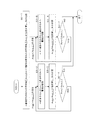
図2はセルCe1〜セルCe5を2グループに分けたとき、グループ毎のセルの平均電圧の一例を示している。このグループ分けは、直列接続された5個のセルCe1〜Ce5を、該直列接続の列順を維持したまま、順々に、2つのグループに分ける。そして、各グループ内のセルの平均電圧を計算する。ここで、セル全体の平均電圧を基準電圧0Vとし、セルCe1は−1V、セルCe2は−2V、セルCe3は+1V、セルCe4は+3V、セルCe5は−1Vであったとする。 FIG. 2 shows an example of the average voltage of the cells for each group when the cells Ce1 to Ce5 are divided into two groups. In this grouping, the five cells Ce1 to Ce5 connected in series are sequentially divided into two groups while maintaining the column order of the series connection. Then, the average voltage of the cells in each group is calculated. Here, it is assumed that the average voltage of the entire cell is 0 V, the cell Ce1 is −1 V, the cell Ce2 is −2 V, the cell Ce3 is +1 V, the cell Ce4 is +3 V, and the cell Ce5 is −1 V.
図2の(a)は、セルCe1のみのグループと、セルCe2〜セルCe5のグループとに分けたとき、セルCe1のみのグループの平均電圧−1V、セルCe2〜セルCe5のグループの平均電圧+0.25Vと計算された例を示している。(この場合、グループの境界はセルCe1とセルCe2との間である。セルCe1とセルCe2はグループの境界に位置するセルであり、また、2グループの境界に位置する隣接セルでもある。)
図2の(b)は、セルCe1〜セルCe2のグループと、セルCe3〜セルCe5のグループとに分けたとき、セルCe1〜セルCe2のグループの平均電圧−1.5V、セルCe3〜セルCe5のグループの平均電圧+1Vと計算された例を示している。(この場合、グループの境界はセルCe2とセルCe3との間である。セルCe2とセルCe3はグループの境界に位置するセルであり、また、2グループの境界に位置する隣接セルでもある。)
図2の(c)は、セルCe1〜セルCe3のグループと、セルCe4〜セルCe5のグループとに分けたとき、セルCe1〜セルCe3のグループの平均電圧−0.67V、セルCe4〜セルCe5のグループの平均電圧+1Vと計算された例を示している。
FIG. 2 (a) shows that when divided into the group of only the cell Ce1 and the group of the cells Ce2 to Ce5, the average voltage of the group of only the cell Ce1 is −1V, and the average voltage of the group of the cells Ce2 to Ce5 is +0. An example calculated as .25V is shown. (In this case, the group boundary is between the cell Ce1 and the cell Ce2. The cell Ce1 and the cell Ce2 are cells located at the boundary of the group, and are also adjacent cells located at the boundary of the two groups.)
(B) of FIG. 2 shows that when the cell Ce1 to the cell Ce2 are divided into the group of the cell Ce3 to the cell Ce5, the group Ce1 to the cell Ce2 has an average voltage −1.5 V, the cell Ce3 to the cell Ce5. In the example shown in FIG. (In this case, the group boundary is between the cell Ce2 and the cell Ce3. The cell Ce2 and the cell Ce3 are cells located at the boundary of the group, and are also adjacent cells located at the boundary of the two groups.)
FIG. 2 (c) shows that when the cell Ce1 to the cell Ce3 are divided into the group of the cell Ce4 to the cell Ce5, the average voltage −0.67V of the cell Ce1 to the cell Ce3, the cell Ce4 to the cell Ce5. In the example shown in FIG.
図2の(d)は、セルCe1〜セルCe4のグループと、セルCe5のみのグループとに分けたとき、セルCe1〜セルCe4のグループの平均電圧+0.25V、セルCe5のみのグループの平均電圧−1Vと計算された例を示している。 FIG. 2 (d) shows the average voltage of the cell Ce1 to cell Ce4 group + 0.25V and the average voltage of the cell Ce5 group when the cell Ce1 to cell Ce4 group and the cell Ce5 only group are divided. An example calculated as −1V is shown.
セルCe1とセルCe2との間には、スイッチングコンバータSC12が介在し、セルCe2とセルCe3との間には、スイッチングコンバータSC23が介在し、セルCe3とセルCe4との間には、スイッチングコンバータSC34が介在し、セルCe4とセルCe5との間には、スイッチングコンバータSC45が介在する。 A switching converter SC12 is interposed between the cell Ce1 and the cell Ce2, a switching converter SC23 is interposed between the cell Ce2 and the cell Ce3, and a switching converter SC34 is interposed between the cell Ce3 and the cell Ce4. And a switching converter SC45 is interposed between the cell Ce4 and the cell Ce5.
ここで、一例としてスイッチングコンバータSC23に注目すると、図2の(b)に示すように、セルCe1とセルCe2の平均電圧−1.5Vと、セルCe3〜セルCe5の平均電圧+1Vとを比較し、平均電圧の低い方のグループのセルCe2(平均電圧の低いグループの境界に位置する隣接セル)へ、平均電圧の高い方のグループのセルCe3(平均電圧の高いグループの境界に位置するセル)から電流をスイッチングコンバータSC23により流す。 Here, focusing on the switching converter SC23 as an example, as shown in FIG. 2 (b), the average voltage -1.5V of the cells Ce1 and Ce2 is compared with the average voltage + 1V of the cells Ce3 to Ce5. , Cell Ce2 of the group with the lower average voltage (adjacent cell located at the boundary of the group with the lower average voltage), cell Ce3 of the group with the higher average voltage (cell located at the boundary of the group with the higher average voltage) Current is passed through the switching converter SC23.
スイッチングコンバータSC23による電流の流出/流入は、セルCe1とセルCと2の平均電圧がセルCe3〜セルCe5の平均電圧と等しくなったとき又はそれを超えたときに停止する。あるいは、セルCe1とセルCe2の平均電圧又はセルCe3〜セルCe5の平均電圧の何れかが、セル全体の平均電圧と、所定の閾値の以下の差となったときに停止する構成としてもよい。 The outflow / inflow of current by the switching converter SC23 stops when the average voltage of the cells Ce1, C2 and 2 becomes equal to or exceeds the average voltage of the cells Ce3 to Ce5. Or it is good also as a structure which stops, when either the average voltage of the cell Ce1 and the cell Ce2 or the average voltage of the cell Ce3-cell Ce5 becomes the difference below the predetermined threshold value with the average voltage of the whole cell.
同様に、その他のスイッチングコンバータSC12,SC34,SC45についても、両側のグループのセルの平均電圧を基に電荷の移動方向を決定する。各スイッチングコンバータSC12,SC23,SC34,SC45は、同時に又は並行して各スイッチ素子を駆動する構成とすることができる。 Similarly, with respect to the other switching converters SC12, SC34, and SC45, the charge moving direction is determined based on the average voltage of the cells in the groups on both sides. Each switching converter SC12, SC23, SC34, SC45 can be configured to drive each switch element simultaneously or in parallel.
このとき、各スイッチングコンバータの動作は、他のスイッチングコンバータの動作による影響を受けない。何故なら、例えばスイッチングコンバータSC23に着目すると、スイッチングコンバータSC23の動作は、セルCe2とセルCe3との間だけの電荷移動であり、この電荷移動によって、他のグループ分けによるグループの平均電圧は変化しないからである。 At this time, the operation of each switching converter is not affected by the operation of other switching converters. This is because, for example, when attention is paid to the switching converter SC23, the operation of the switching converter SC23 is charge transfer only between the cell Ce2 and the cell Ce3, and the average voltage of the group due to other grouping does not change by this charge transfer. Because.
即ち、セルCe2とセルCe3との間の電荷移動だけでは、図2の(a)のグループ分けによるセルCe2〜Ce5のグループでは、同一グループ内のセル間での電荷移動となるため、セルCe2〜Ce5のグループの平均電圧に変化は生じない。同様に、図2の(c)のグループ分けによるセルCe1〜Ce3のグループでも、同一グループ内のセル間での電荷移動となるため、セルCe1〜Ce3のグループの平均電圧に変化は生じない。また、図2の(d)のグループ分けによるセルCe1〜Ce4のグループでも、同一グループ内のセル間での電荷移動となるため、セルCe1〜Ce4のグループの平均電圧に変化は生じない。 That is, only the charge transfer between the cell Ce2 and the cell Ce3 causes the charge transfer between the cells in the same group in the group of the cells Ce2 to Ce5 by the grouping of FIG. No change occurs in the average voltage of the group of ~ Ce5. Similarly, even in the group of cells Ce1 to Ce3 by the grouping in FIG. 2C, charge transfer is performed between cells in the same group, so that the average voltage of the group of cells Ce1 to Ce3 does not change. Further, even in the group of the cells Ce1 to Ce4 by the grouping of FIG. 2D, charge transfer is performed between cells in the same group, so that the average voltage of the group of the cells Ce1 to Ce4 does not change.
また、他のスイッチングコンバータSC12、SC34、SC45による電荷移動も、スイッチングコンバータSC23の動作に影響を与えない。即ち、スイッチングコンバータSC12による電荷移動は、セルCe1とセルCe2との間だけの電荷移動であり、スイッチングコンバータSC34による電荷移動は、セルCe3とセルCe4との間だけの電荷移動であり、スイッチングコンバータSC45による電荷移動は、セルCe4とセルCe5との間だけの電荷移動であるため、セルCe1とセルCe2のグループと、セル3〜セル5のグループの各平均電圧に影響を与えない。 Further, the charge transfer caused by the other switching converters SC12, SC34, SC45 does not affect the operation of the switching converter SC23. That is, the charge transfer by the switching converter SC12 is only charge transfer between the cell Ce1 and the cell Ce2, and the charge transfer by the switching converter SC34 is only charge transfer between the cell Ce3 and the cell Ce4. Since the charge transfer by SC45 is a charge transfer only between the cells Ce4 and Ce5, it does not affect the average voltages of the groups of the cells Ce1 and Ce2 and the groups of the cells 3 to 5.
従って、スイッチングコンバータSC12、SC23、SC34、SC45を、独立に駆動することができ、制御部1−4は、各スイッチングコンバータSC12、SC23、SC34、SC45を同時に又は並行して駆動することにより、セルバランスの動作時間を短縮することが可能となる。 Therefore, the switching converters SC12, SC23, SC34, and SC45 can be driven independently, and the control unit 1-4 drives the switching converters SC12, SC23, SC34, and SC45 simultaneously or in parallel, thereby It is possible to shorten the balance operation time.
図3は、本発明によるセルバランス方法の第1の実施例のフローを示す。図3は、直列接続されたセルのm番目とm+1番目の列順の隣接セルに対する電荷移動の動作例を示している。なお、セルの全個数はn個であるとする。第1の実施例では、まず、第1番目から第m番目までのセルのグループの平均電圧Avmと、m+1番目からn番目までのセルのグループの平均電圧Avm+1とを計算し、AvmとAvm+1との大小比較を行う(S3−1)。 FIG. 3 shows the flow of the first embodiment of the cell balance method according to the present invention. FIG. 3 shows an operation example of charge transfer with respect to adjacent cells in the m-th and m + 1-th column order of cells connected in series. It is assumed that the total number of cells is n. In the first embodiment, firstly, the average voltage Av m groups of cells from the first to the m-th and the average voltage Av m + 1 of the group of cells from m + 1 th to n-th calculated, Av m And Av m + 1 are compared (S3-1).
比較の結果、AvmがAvm+1より大きい場合、m番目のセルからm+1番目のセルへ電荷を移動させるよう、スイッチ素子のON/OFF制御を行う(S3−2)。そして、電荷移動後のAvmとAvm+1とを計算し、その大小比較を行う(S3−3)。AvmがAvm+1よりなお大きい場合(S3−4YES)、再び、m番目のセルからm+1番目のセルへ電荷を移動させるよう、スイッチ素子のON/OFF制御を行い(S3−2)。AvmがAvm+1より小さいかAvm+1と等しくなった場合(S3−4NO)、動作を終了する。 If Av m is larger than Av m + 1 as a result of the comparison, ON / OFF control of the switch element is performed so as to move the charge from the m-th cell to the m + 1-th cell (S3-2). Then, Av m and Av m + 1 after the charge transfer are calculated, and the magnitudes are compared (S3-3). When Av m is still larger than Av m + 1 (YES in S3-4), ON / OFF control of the switch element is performed again so as to move the charge from the mth cell to the m + 1st cell (S3-2). If Av m is equal to Av m + 1 less than or Av m + 1 (S3-4NO), the operation ends.
また、比較の結果、AvmがAvm+1より小さい場合、m+1番目のセルからm番目のセルへ電荷を移動させるよう、スイッチ素子のON/OFF制御を行う(S3−5)。そして、電荷移動後のAvmとAvm+1とを計算し、その大小比較を行う(S3−6)。AvmがAvm+1よりなお小さい場合(S3−7YES)、再び、m+1番目のセルからm番目のセルへ電荷を移動させるよう、スイッチ素子のON/OFF制御を行い(S3−6)。AvmがAvm+1より大きいかAvm+1と等しくなった場合(S3−7NO)、動作を終了する。 If the comparison result shows that Av m is smaller than Av m + 1 , the switch element is turned on / off so that the charge is transferred from the m + 1 th cell to the m th cell (S3-5). Then, Av m and Av m + 1 after the charge transfer are calculated, and the magnitude comparison is performed (S3-6). When Av m is still smaller than Av m + 1 (YES in S3-7), ON / OFF control of the switch element is performed again so as to move the charge from the m + 1st cell to the mth cell (S3-6). If Av m is equal to Av m + 1 greater than or Av m + 1 (S3-7NO), the operation ends.
図4は、本発明によるセルバランス方法の第2の実施例のフローを示す。図4も同様に、直列接続されたセルのm番目とm+1番目の列順の隣接セルに対する電荷移動の動作例を示し、セルの全個数はn個であるとする。第2の実施例では、2つに分けたグループの一方のみのセルの平均電圧と、セル全体の平均電圧を計算し、その大小比較により電荷の移動方向を決定するものである。 FIG. 4 shows the flow of a second embodiment of the cell balance method according to the present invention. Similarly, FIG. 4 shows an example of the charge transfer operation for the m-th and m + 1-th adjacent columns of cells connected in series, and the total number of cells is n. In the second embodiment, the average voltage of only one cell in the group divided into two and the average voltage of the whole cell are calculated, and the charge movement direction is determined by comparing the magnitudes.
セル間の電荷の移動ではセル全体の平均電圧は変化しないので、セル全体の平均電圧は1回計算すればよい。そして、2つに分けたグループの平均電圧は、一方のグループの平均電圧が他方のグループの平均電圧より低ければ、必ず、該一方のグループの平均電圧はセル全体の平均電圧より低く、該他方のグループの平均電圧はセル全体の平均電圧より高くなる。 Since the average voltage of the whole cell does not change in the movement of charge between cells, the average voltage of the whole cell may be calculated once. The average voltage of the two divided groups is always lower than the average voltage of the whole cell if the average voltage of one group is lower than the average voltage of the other group. The average voltage of this group is higher than the average voltage of the entire cell.
従って、両グループの平均電圧を比較する第1の実施例に代えて、一方のグループの平均電圧とセル全体の平均電圧とを比較して電荷の移動方向を決定することができ、グループの平均電圧の計算処理を1グループのみとすることにより、計算の処理負担を軽減することが可能となる。第2の実施例は、このような動作原理に基づくものである。 Therefore, instead of the first embodiment in which the average voltages of both groups are compared, the charge transfer direction can be determined by comparing the average voltage of one group with the average voltage of the entire cell. By limiting the voltage calculation processing to only one group, it is possible to reduce the calculation processing load. The second embodiment is based on such an operation principle.
図4を参照して第2の実施例の動作フローを説明する。まず、n個の全セルの平均電圧Avnを計算する(S4−1)。次に、第1番目から第m番目までのセルのグループの平均電圧Avmを計算し、AvmとAvnとの大小比較を行う(S4−2)。 The operation flow of the second embodiment will be described with reference to FIG. First, an average voltage Av n of all n cells is calculated (S4-1). Next, the average voltage Av m of the first to m-th cell groups is calculated, and Av m and Av n are compared in magnitude (S4-2).
比較の結果、AvmがAvnより大きい場合、m番目のセルからm+1番目のセルへ電荷を移動させるよう、スイッチ素子のON/OFF制御を行う(S4−3)。そして、電荷移動後のAvmを計算し、Avnと大小比較を行う(S4−4)。AvmがAvnよりなお大きい場合(S4−5YES)、再び、m番目のセルからm+1番目のセルへ電荷を移動させるよう、スイッチ素子のON/OFF制御を行い(S4−3)。AvmがAvnより小さいかAvnと等しくなった場合(S4−5NO)、動作を終了する。 If Av m is larger than Av n as a result of the comparison, ON / OFF control of the switch element is performed so as to move the charge from the mth cell to the m + 1st cell (S4-3). Then, Av m after the charge transfer is calculated, and the magnitude is compared with Av n (S4-4). When Av m is still larger than Av n (S4-5 YES), the switch element is turned ON / OFF again to move the charge from the mth cell to the m + 1st cell (S4-3). If Av m is equal to Av n less than or Av n (S4-5NO), the operation ends.
また、比較の結果、AvmがAvnより小さい場合、m+1番目のセルからm番目のセルへ電荷を移動させるよう、スイッチ素子のON/OFF制御を行う(S4−6)。そして、電荷移動後のAvmを計算し、Avnと大小比較を行う(S4−7)。AvmがAvnよりなお小さい場合(S4−8YES)、再び、m+1番目のセルからm番目のセルへ電荷を移動させるよう、スイッチ素子のON/OFF制御を行い(S4−6)、AvmがAvnより大きいかAvnと等しくなった場合(S4−8NO)、動作を終了する。 On the other hand, if Av m is smaller than Av n as a result of the comparison, ON / OFF control of the switch element is performed so as to move the charge from the (m + 1) th cell to the mth cell (S4-6). Then, Av m after the charge transfer is calculated, and the magnitude is compared with Av n (S4-7). When Av m is still smaller than Av n (S4-8 YES), ON / OFF control of the switch element is performed again so as to move the charge from the (m + 1) th cell to the mth cell (S4-6), and Av m If a is equal to the Av n greater than or Av n (S4-8NO), the operation ends.
以上説明した2つのグループ分けによる、グループの境界位置の隣接セル間での電荷移動によるセルバランスは、それぞれのグループ分けのグループ境界位置の隣接セル間で、同時に実施してもよく、また、時系列的に順々に行ってもよい。なお、本発明は、以上に述べた実施の形態に限定されるものではなく、本発明の要旨を逸脱しない範囲内で種々の構成または実施形態を取ることができる。 The cell balance by the charge transfer between the adjacent cells at the group boundary position by the two grouping described above may be performed simultaneously between the adjacent cells at the group boundary position of each grouping. You may go sequentially in sequence. The present invention is not limited to the above-described embodiment, and various configurations or embodiments can be taken without departing from the gist of the present invention.
1−1 平均電圧計算部
1−2 2グループの平均電圧比較部
1−3 スイッチ素子オン/オフ制御部
1−4 制御部
Ce1,Ce2,Ce3,Ce4,Ce5 セル
L12,L23,L34,L45 インダクタ
Sw12,Sw21,Sw23,Sw32,Sw34,Sw43,Sw45,Sw54 スイッチ素子
D21,D12,D32,D23,D43,D34,D54,D45 ダイオード
SC12,SC23,SC34,SC45 スイッチングコンバータ
1-1 Average Voltage Calculation Unit 1-2 Two Group Average Voltage Comparison Unit 1-3 Switch Element On / Off Control Unit 1-4 Control Unit Ce1, Ce2, Ce3, Ce4, Ce5 Cell L12, L23, L34, L45 Inductor Sw12, Sw21, Sw23, Sw32, Sw34, Sw43, Sw45, Sw54 Switch elements D21, D12, D32, D23, D43, D34, D54, D45 Diodes SC12, SC23, SC34, SC45 Switching converter
Claims (6)
ルの接続点にインダクタの一端を接続し、該インダクタの他端を、該隣接するセルの他端
にそれぞれスイッチ素子を介して接続し、該スイッチ素子のオン/オフ制御により、隣接
するセル間で電荷を移動させ、各セルの電圧を均等化するセルバランス装置において、
前記直列接続された複数のセルを、該直列接続の列順を維持したまま、順次、2つのグループに分けて、各グループ内のセルの平均電圧を計算する平均電圧計算手段と、
前記平均電圧計算手段で計算した2つのグループの平均電圧同士を比較する平均電圧比
較手段と、
前記平均電圧比較手段の比較結果を基に、前記平均電圧の高いグループの境界に位置す
るセルから、前記平均電圧の低いグループの境界に位置する隣接セルへ、電荷を移動させ
るよう、前記スイッチ素子のオン/オフ制御を行うオン/オフ制御手段と、
を備えたことを特徴とするセルバランス装置。 One end of an inductor is connected to a connection point of adjacent cells with respect to at least three power storage elements (hereinafter referred to as “cells”) connected in series, and the other end of the inductor is connected to the other end of the adjacent cell, respectively. In a cell balance device that connects via a switch element, moves charges between adjacent cells by on / off control of the switch element, and equalizes the voltage of each cell.
Average voltage calculation means for dividing the plurality of cells connected in series into two groups sequentially while maintaining the column order of the series connection, and calculating the average voltage of the cells in each group;
Average voltage comparison means for comparing the average voltages of the two groups calculated by the average voltage calculation means;
Based on the comparison result of the average voltage comparison means, the switching element moves the charge from the cell located at the boundary of the group having a high average voltage to the adjacent cell located at the boundary of the group having a low average voltage. ON / OFF control means for performing ON / OFF control of
A cell balance device comprising:
ルの接続点にインダクタの一端を接続し、該インダクタの他端を、該隣接するセルの他端
にそれぞれスイッチ素子を介して接続し、該スイッチ素子のオン/オフ制御により、隣接
するセル間で電荷を移動させ、各セルの電圧を均等化するセルバランス装置において、
前記直列接続された複数のセルを、該直列接続の列順を維持したまま、順次、2つのグループに分けて、一方のグループのセルの平均電圧と全セルの平均電圧とを計算する平均電圧計算手段と、
前記平均電圧計算手段で計算した一方のグループの平均電圧と全セルの平均電圧とを比
較する平均電圧比較手段と、
前記平均電圧比較手段の比較結果を基に、一方のグループの平均電圧が全セルの平均電
圧より高いときは、該一方のグループの境界に位置するセルから、他方のグループの境界
に位置する隣接セルへ電荷を移動させ、前記一方のグループの平均電圧が全セルの平均電
圧より低いときは、該一方のグループの境界に位置するセルへ、前記他方のグループの境
界に位置する隣接セルから電荷を移動させるよう、前記スイッチ素子のオン/オフ制御を
行うオン/オフ制御手段と、
を備えたことを特徴とするセルバランス装置。 One end of an inductor is connected to a connection point of adjacent cells with respect to at least three power storage elements (hereinafter referred to as “cells”) connected in series, and the other end of the inductor is connected to the other end of the adjacent cell, respectively. In a cell balance device that connects via a switch element, moves charges between adjacent cells by on / off control of the switch element, and equalizes the voltage of each cell.
The average voltage for calculating the average voltage of the cells in one group and the average voltage of all the cells by sequentially dividing the plurality of cells connected in series into two groups while maintaining the column order of the series connection Calculation means;
An average voltage comparison means for comparing the average voltage of one group calculated by the average voltage calculation means with the average voltage of all cells;
Based on the comparison result of the average voltage comparison means, when the average voltage of one group is higher than the average voltage of all the cells, the cell located at the boundary of the one group is adjacent to the boundary of the other group. When charge is transferred to a cell and the average voltage of the one group is lower than the average voltage of all the cells, the charge is transferred from the adjacent cell located at the boundary of the other group to the cell located at the boundary of the other group. ON / OFF control means for performing ON / OFF control of the switch element so as to move
A cell balance device comprising:
ルの接続点にインダクタの一端を接続し、該インダクタの他端を、該隣接するセルの他端
にそれぞれスイッチ素子を介して接続した回路を用い、該スイッチ素子のオン/オフ制御
により、隣接するセル間で電荷を移動させ、各セルの電圧を均等化するセルバランス方法
において、
前記直列接続された複数のセルを、該直列接続の列順を維持したまま、順次、2つのグループに分けて、各グループ内のセルの平均電圧を計算するステップと、
前記2つのグループのセルの平均電圧同士を比較するステップと、
前記比較の結果を基に、前記平均電圧の高いグループの境界に位置するセルから、前記
平均電圧の低いグループの境界に位置する隣接セルへ、電荷を移動させるよう、前記スイ
ッチ素子のオン/オフ制御を行うステップと、
を含むことを特徴とするセルバランス方法。 One end of an inductor is connected to a connection point of adjacent cells with respect to at least three power storage elements (hereinafter referred to as “cells”) connected in series, and the other end of the inductor is connected to the other end of the adjacent cell, respectively. In a cell balance method that uses a circuit connected via a switch element, moves charges between adjacent cells by on / off control of the switch element, and equalizes the voltage of each cell.
Dividing the plurality of cells connected in series into two groups sequentially while maintaining the column order of the series connection, and calculating an average voltage of the cells in each group;
Comparing the average voltages of the two groups of cells;
Based on the result of the comparison, the switch element is turned on / off so as to transfer charges from the cell located at the boundary of the group having a high average voltage to the adjacent cell located at the boundary of the group having a low average voltage. Performing the control;
A cell balance method comprising:
ルの接続点にインダクタの一端を接続し、該インダクタの他端を、該隣接するセルの他端
にそれぞれスイッチ素子を介して接続した回路を用い、該スイッチ素子のオン/オフ制御
により、隣接するセル間で電荷を移動させ、各セルの電圧を均等化するセルバランス方法
において、
前記直列接続された複数のセルを、該直列接続の列順を維持したまま、順次、2つのグループに分けて、一方のグループのセルの平均電圧と全セルの平均電圧とを計算するステップと、
前記一方のグループのセルの平均電圧と前記全セルの平均電圧とを比較するステップと
、
前記比較の結果を基に、前記一方のグループの平均電圧が前記全セルの平均電圧より高
いときは、該一方のグループの境界に位置するセルから、他方のグループの境界に位置す
る隣接セルへ電荷を移動させ、前記一方のグループの平均電圧が全セルの平均電圧より低
いときは、該一方のグループの境界に位置するセルへ、前記他方のグループの境界に位置
する隣接セルから電荷を移動させるよう、前記スイッチ素子のオン/オフ制御を行うステ
ップと、
を含むことを特徴とするセルバランス方法。 One end of an inductor is connected to a connection point of adjacent cells with respect to at least three power storage elements (hereinafter referred to as “cells”) connected in series, and the other end of the inductor is connected to the other end of the adjacent cell, respectively. In a cell balance method that uses a circuit connected via a switch element, moves charges between adjacent cells by on / off control of the switch element, and equalizes the voltage of each cell.
Dividing the plurality of cells connected in series into two groups sequentially while maintaining the column order of the series connection, and calculating an average voltage of cells of one group and an average voltage of all cells; ,
Comparing the average voltage of the one group of cells with the average voltage of all the cells;
Based on the result of the comparison, when the average voltage of the one group is higher than the average voltage of all the cells, from the cell located at the boundary of the one group to the adjacent cell located at the boundary of the other group When charge is transferred and the average voltage of the one group is lower than the average voltage of all cells, the charge is transferred from the adjacent cell located at the boundary of the other group to the cell located at the boundary of the other group. Performing an on / off control of the switch element so that
A cell balance method comprising:
Priority Applications (5)
| Application Number | Priority Date | Filing Date | Title |
|---|---|---|---|
| JP2012181591A JP5817678B2 (en) | 2012-08-20 | 2012-08-20 | Cell balance device and cell balance method |
| EP13830364.9A EP2887495A4 (en) | 2012-08-20 | 2013-08-12 | Cell balancing device and cell balancing method |
| PCT/JP2013/071806 WO2014030569A1 (en) | 2012-08-20 | 2013-08-12 | Cell balancing device and cell balancing method |
| CN201380040340.0A CN104508940A (en) | 2012-08-20 | 2013-08-12 | Cell balancing device and cell balancing method |
| US14/412,075 US20150171643A1 (en) | 2012-08-20 | 2013-08-12 | Cell balance apparatus and cell balance method |
Applications Claiming Priority (1)
| Application Number | Priority Date | Filing Date | Title |
|---|---|---|---|
| JP2012181591A JP5817678B2 (en) | 2012-08-20 | 2012-08-20 | Cell balance device and cell balance method |
Publications (3)
| Publication Number | Publication Date |
|---|---|
| JP2014039435A JP2014039435A (en) | 2014-02-27 |
| JP2014039435A5 JP2014039435A5 (en) | 2015-01-15 |
| JP5817678B2 true JP5817678B2 (en) | 2015-11-18 |
Family
ID=50149878
Family Applications (1)
| Application Number | Title | Priority Date | Filing Date |
|---|---|---|---|
| JP2012181591A Expired - Fee Related JP5817678B2 (en) | 2012-08-20 | 2012-08-20 | Cell balance device and cell balance method |
Country Status (5)
| Country | Link |
|---|---|
| US (1) | US20150171643A1 (en) |
| EP (1) | EP2887495A4 (en) |
| JP (1) | JP5817678B2 (en) |
| CN (1) | CN104508940A (en) |
| WO (1) | WO2014030569A1 (en) |
Families Citing this family (4)
| Publication number | Priority date | Publication date | Assignee | Title |
|---|---|---|---|---|
| DE112014001885T5 (en) * | 2013-04-09 | 2016-01-21 | Evtd Inc. | Voltage compensation device and electrical storage system |
| JP6133110B2 (en) * | 2013-04-09 | 2017-05-24 | Evtd株式会社 | Balance correction device and power storage system |
| JP6234049B2 (en) * | 2013-04-09 | 2017-11-22 | NExT−e Solutions株式会社 | Balance correction device and power storage system |
| EP4094978A1 (en) * | 2016-12-12 | 2022-11-30 | Honeywell International Inc. | Adaptive balancing for battery management |
Family Cites Families (8)
| Publication number | Priority date | Publication date | Assignee | Title |
|---|---|---|---|---|
| US5479083A (en) * | 1993-06-21 | 1995-12-26 | Ast Research, Inc. | Non-dissipative battery charger equalizer |
| US6150795A (en) * | 1999-11-05 | 2000-11-21 | Power Designers, Llc | Modular battery charge equalizers and method of control |
| JP4590379B2 (en) * | 2006-08-01 | 2010-12-01 | Fdk株式会社 | System for charging / discharging multiple series storage cells |
| KR101220339B1 (en) * | 2007-10-16 | 2013-01-09 | 한국과학기술원 | Automatic Charge Equalization Method and Apparatus for Series Connected Battery String |
| JP2010220373A (en) | 2009-03-17 | 2010-09-30 | Fuji Electric Systems Co Ltd | Balancing circuit of energy storage element |
| JP5197891B2 (en) * | 2011-05-24 | 2013-05-15 | パナソニック株式会社 | Power storage device, portable device and electric vehicle |
| EP2541728A2 (en) * | 2011-06-30 | 2013-01-02 | Kabushiki Kaisha Toyota Jidoshokki | Cell balancing device |
| JP5482809B2 (en) * | 2012-01-31 | 2014-05-07 | 株式会社豊田自動織機 | Equalization equipment |
-
2012
- 2012-08-20 JP JP2012181591A patent/JP5817678B2/en not_active Expired - Fee Related
-
2013
- 2013-08-12 CN CN201380040340.0A patent/CN104508940A/en active Pending
- 2013-08-12 EP EP13830364.9A patent/EP2887495A4/en not_active Withdrawn
- 2013-08-12 US US14/412,075 patent/US20150171643A1/en not_active Abandoned
- 2013-08-12 WO PCT/JP2013/071806 patent/WO2014030569A1/en active Application Filing
Also Published As
| Publication number | Publication date |
|---|---|
| US20150171643A1 (en) | 2015-06-18 |
| EP2887495A4 (en) | 2016-01-13 |
| JP2014039435A (en) | 2014-02-27 |
| WO2014030569A1 (en) | 2014-02-27 |
| EP2887495A1 (en) | 2015-06-24 |
| CN104508940A (en) | 2015-04-08 |
Similar Documents
| Publication | Publication Date | Title |
|---|---|---|
| US11196264B2 (en) | Modular energy storage direct converter system | |
| KR102176586B1 (en) | Balancing apparatus for balancing cells included in battery, and battery module | |
| JP5817678B2 (en) | Cell balance device and cell balance method | |
| JP6465358B2 (en) | Voltage equalization circuit system | |
| KR101942970B1 (en) | Balancing method and battery system | |
| CN102882242B (en) | Circuit for charging and discharging balance of storage battery pack | |
| US9356467B2 (en) | Charge balancing circuit for series connected chains of charge storage elements | |
| KR101632694B1 (en) | Battery cell voltage balancing apparatus and method | |
| JP2011055649A5 (en) | ||
| CN102623768B (en) | Multi-battery charging method and device and handheld mobile terminal | |
| CN102142691B (en) | For the circuit using together with energy converter | |
| RU2015117057A (en) | MULTI-LEVEL POWER CONVERTER | |
| JP2015508275A5 (en) | ||
| RU2011124556A (en) | METHOD FOR CHARGING A LITHIUM-ION BATTERY BATTERY FROM n SEQUENTLY CONNECTED BATTERIES WITH CONNECTORS TO THEM THROUGH BALANCING RESISTORS SWITCHES | |
| CN108493968B (en) | Flywheel energy storage array and energy balance control method thereof | |
| JP5609476B2 (en) | Secondary battery charge / discharge device and power storage system | |
| JP2014039435A5 (en) | ||
| CN105490329A (en) | Series-wound battery pack equalization circuit based on inductor charge/discharge energy transfer | |
| Kanta et al. | Design of a bi-directional DC-DC 4 phase interleave converter for PV applications | |
| JP2013078194A (en) | Power supply system | |
| JP2016046836A (en) | Non-insulated cell balance circuit | |
| CN108551180A (en) | Battery equalization method and balanced device | |
| RU2662151C1 (en) | Device for direct control of the moment of a synchronous engine | |
| CN203734331U (en) | Series-connected battery pack equalization device based on bidirectional direct-current converters | |
| RU2505914C2 (en) | Dc voltage converter |
Legal Events
| Date | Code | Title | Description |
|---|---|---|---|
| A521 | Request for written amendment filed |
Free format text: JAPANESE INTERMEDIATE CODE: A523 Effective date: 20141106 |
|
| A621 | Written request for application examination |
Free format text: JAPANESE INTERMEDIATE CODE: A621 Effective date: 20141106 |
|
| A521 | Request for written amendment filed |
Free format text: JAPANESE INTERMEDIATE CODE: A523 Effective date: 20141126 |
|
| TRDD | Decision of grant or rejection written | ||
| A01 | Written decision to grant a patent or to grant a registration (utility model) |
Free format text: JAPANESE INTERMEDIATE CODE: A01 Effective date: 20150901 |
|
| A61 | First payment of annual fees (during grant procedure) |
Free format text: JAPANESE INTERMEDIATE CODE: A61 Effective date: 20150914 |
|
| R151 | Written notification of patent or utility model registration |
Ref document number: 5817678 Country of ref document: JP Free format text: JAPANESE INTERMEDIATE CODE: R151 |
|
| LAPS | Cancellation because of no payment of annual fees |