JP5816191B2 - Drive assembly for drug delivery device and drug delivery device - Google Patents
Drive assembly for drug delivery device and drug delivery device Download PDFInfo
- Publication number
- JP5816191B2 JP5816191B2 JP2012542483A JP2012542483A JP5816191B2 JP 5816191 B2 JP5816191 B2 JP 5816191B2 JP 2012542483 A JP2012542483 A JP 2012542483A JP 2012542483 A JP2012542483 A JP 2012542483A JP 5816191 B2 JP5816191 B2 JP 5816191B2
- Authority
- JP
- Japan
- Prior art keywords
- drive assembly
- housing
- drive member
- piston rod
- section
- Prior art date
- Legal status (The legal status is an assumption and is not a legal conclusion. Google has not performed a legal analysis and makes no representation as to the accuracy of the status listed.)
- Expired - Fee Related
Links
Images


Classifications
-
- A—HUMAN NECESSITIES
- A61—MEDICAL OR VETERINARY SCIENCE; HYGIENE
- A61M—DEVICES FOR INTRODUCING MEDIA INTO, OR ONTO, THE BODY; DEVICES FOR TRANSDUCING BODY MEDIA OR FOR TAKING MEDIA FROM THE BODY; DEVICES FOR PRODUCING OR ENDING SLEEP OR STUPOR
- A61M5/00—Devices for bringing media into the body in a subcutaneous, intra-vascular or intramuscular way; Accessories therefor, e.g. filling or cleaning devices, arm-rests
- A61M5/178—Syringes
- A61M5/31—Details
- A61M5/315—Pistons; Piston-rods; Guiding, blocking or restricting the movement of the rod or piston; Appliances on the rod for facilitating dosing ; Dosing mechanisms
- A61M5/31533—Dosing mechanisms, i.e. setting a dose
- A61M5/31545—Setting modes for dosing
- A61M5/31548—Mechanically operated dose setting member
- A61M5/3156—Mechanically operated dose setting member using volume steps only adjustable in discrete intervals, i.e. individually distinct intervals
-
- A—HUMAN NECESSITIES
- A61—MEDICAL OR VETERINARY SCIENCE; HYGIENE
- A61M—DEVICES FOR INTRODUCING MEDIA INTO, OR ONTO, THE BODY; DEVICES FOR TRANSDUCING BODY MEDIA OR FOR TAKING MEDIA FROM THE BODY; DEVICES FOR PRODUCING OR ENDING SLEEP OR STUPOR
- A61M5/00—Devices for bringing media into the body in a subcutaneous, intra-vascular or intramuscular way; Accessories therefor, e.g. filling or cleaning devices, arm-rests
- A61M5/178—Syringes
- A61M5/31—Details
- A61M5/315—Pistons; Piston-rods; Guiding, blocking or restricting the movement of the rod or piston; Appliances on the rod for facilitating dosing ; Dosing mechanisms
- A61M5/31565—Administration mechanisms, i.e. constructional features, modes of administering a dose
- A61M5/3159—Dose expelling manners
- A61M5/31593—Multi-dose, i.e. individually set dose repeatedly administered from the same medicament reservoir
-
- A—HUMAN NECESSITIES
- A61—MEDICAL OR VETERINARY SCIENCE; HYGIENE
- A61M—DEVICES FOR INTRODUCING MEDIA INTO, OR ONTO, THE BODY; DEVICES FOR TRANSDUCING BODY MEDIA OR FOR TAKING MEDIA FROM THE BODY; DEVICES FOR PRODUCING OR ENDING SLEEP OR STUPOR
- A61M5/00—Devices for bringing media into the body in a subcutaneous, intra-vascular or intramuscular way; Accessories therefor, e.g. filling or cleaning devices, arm-rests
- A61M5/178—Syringes
- A61M5/31—Details
- A61M2005/3103—Leak prevention means for distal end of syringes, i.e. syringe end for mounting a needle
-
- A—HUMAN NECESSITIES
- A61—MEDICAL OR VETERINARY SCIENCE; HYGIENE
- A61M—DEVICES FOR INTRODUCING MEDIA INTO, OR ONTO, THE BODY; DEVICES FOR TRANSDUCING BODY MEDIA OR FOR TAKING MEDIA FROM THE BODY; DEVICES FOR PRODUCING OR ENDING SLEEP OR STUPOR
- A61M5/00—Devices for bringing media into the body in a subcutaneous, intra-vascular or intramuscular way; Accessories therefor, e.g. filling or cleaning devices, arm-rests
- A61M5/178—Syringes
- A61M5/31—Details
- A61M2005/3125—Details specific display means, e.g. to indicate dose setting
- A61M2005/3126—Specific display means related to dosing
-
- A—HUMAN NECESSITIES
- A61—MEDICAL OR VETERINARY SCIENCE; HYGIENE
- A61M—DEVICES FOR INTRODUCING MEDIA INTO, OR ONTO, THE BODY; DEVICES FOR TRANSDUCING BODY MEDIA OR FOR TAKING MEDIA FROM THE BODY; DEVICES FOR PRODUCING OR ENDING SLEEP OR STUPOR
- A61M5/00—Devices for bringing media into the body in a subcutaneous, intra-vascular or intramuscular way; Accessories therefor, e.g. filling or cleaning devices, arm-rests
- A61M5/178—Syringes
- A61M5/24—Ampoule syringes, i.e. syringes with needle for use in combination with replaceable ampoules or carpules, e.g. automatic
-
- A—HUMAN NECESSITIES
- A61—MEDICAL OR VETERINARY SCIENCE; HYGIENE
- A61M—DEVICES FOR INTRODUCING MEDIA INTO, OR ONTO, THE BODY; DEVICES FOR TRANSDUCING BODY MEDIA OR FOR TAKING MEDIA FROM THE BODY; DEVICES FOR PRODUCING OR ENDING SLEEP OR STUPOR
- A61M5/00—Devices for bringing media into the body in a subcutaneous, intra-vascular or intramuscular way; Accessories therefor, e.g. filling or cleaning devices, arm-rests
- A61M5/178—Syringes
- A61M5/31—Details
- A61M5/315—Pistons; Piston-rods; Guiding, blocking or restricting the movement of the rod or piston; Appliances on the rod for facilitating dosing ; Dosing mechanisms
- A61M5/31533—Dosing mechanisms, i.e. setting a dose
- A61M5/31545—Setting modes for dosing
- A61M5/31548—Mechanically operated dose setting member
- A61M5/31555—Mechanically operated dose setting member by purely axial movement of dose setting member, e.g. during setting or filling of a syringe
-
- A—HUMAN NECESSITIES
- A61—MEDICAL OR VETERINARY SCIENCE; HYGIENE
- A61M—DEVICES FOR INTRODUCING MEDIA INTO, OR ONTO, THE BODY; DEVICES FOR TRANSDUCING BODY MEDIA OR FOR TAKING MEDIA FROM THE BODY; DEVICES FOR PRODUCING OR ENDING SLEEP OR STUPOR
- A61M5/00—Devices for bringing media into the body in a subcutaneous, intra-vascular or intramuscular way; Accessories therefor, e.g. filling or cleaning devices, arm-rests
- A61M5/178—Syringes
- A61M5/31—Details
- A61M5/315—Pistons; Piston-rods; Guiding, blocking or restricting the movement of the rod or piston; Appliances on the rod for facilitating dosing ; Dosing mechanisms
- A61M5/31565—Administration mechanisms, i.e. constructional features, modes of administering a dose
- A61M5/31576—Constructional features or modes of drive mechanisms for piston rods
- A61M5/31583—Constructional features or modes of drive mechanisms for piston rods based on rotational translation, i.e. movement of piston rod is caused by relative rotation between the user activated actuator and the piston rod
- A61M5/31585—Constructional features or modes of drive mechanisms for piston rods based on rotational translation, i.e. movement of piston rod is caused by relative rotation between the user activated actuator and the piston rod performed by axially moving actuator, e.g. an injection button
-
- A—HUMAN NECESSITIES
- A61—MEDICAL OR VETERINARY SCIENCE; HYGIENE
- A61M—DEVICES FOR INTRODUCING MEDIA INTO, OR ONTO, THE BODY; DEVICES FOR TRANSDUCING BODY MEDIA OR FOR TAKING MEDIA FROM THE BODY; DEVICES FOR PRODUCING OR ENDING SLEEP OR STUPOR
- A61M5/00—Devices for bringing media into the body in a subcutaneous, intra-vascular or intramuscular way; Accessories therefor, e.g. filling or cleaning devices, arm-rests
- A61M5/48—Devices for bringing media into the body in a subcutaneous, intra-vascular or intramuscular way; Accessories therefor, e.g. filling or cleaning devices, arm-rests having means for varying, regulating, indicating or limiting injection pressure
- A61M5/482—Varying injection pressure, e.g. by varying speed of injection
Description
本発明は、薬物送達デバイスに好適な駆動アセンブリ及び薬物送達デバイスに関する。 The present invention relates to a drive assembly and a drug delivery device suitable for a drug delivery device.
当該薬物送達デバイスは、正式な医学訓練のない使用者が薬物又は薬物の正確なそして事前に定義された用量を投与するのに必要な場合に適用し得る。特に、当該デバイスは、薬物が短期又は長期間にわたって定期的又は非定期的ベースで投与される場合に適用し得る。 The drug delivery device may be applied when a user without formal medical training needs to administer a drug or an accurate and predefined dose of a drug. In particular, the device may be applied when the drug is administered on a regular or non-regular basis over a short or long period.
特許文献1は自動注射デバイスを開示している。さらなる注射デバイスは、US2006/229570A1、WO2009/136209A1、WO00/62847A1、US4475905A、及びUS5256152Aからも知られている。 Patent Document 1 discloses an automatic injection device. Further injection devices are also known from US 2006/229570 A1, WO 2009/136209 A1, WO 00/62847 A1, US 4475905 A, and US 5256152A.
本発明の目的は改良操作性を備えた駆動アセンブリを提供することである。本発明の更なる目的は、使い易いそして薬物の正確な送達が可能な薬物送達デバイスを提供することである。 It is an object of the present invention to provide a drive assembly with improved operability. It is a further object of the present invention to provide a drug delivery device that is easy to use and capable of accurate drug delivery.
本目的は、請求項1に記載の駆動アセンブリ及び請求項14に記載の薬物送達デバイスによって達成される。有利な実施態様は従属クレームの対象である。
This object is achieved by a drive assembly according to claim 1 and a drug delivery device according to
第1の態様によれば、薬物送達デバイスに好適な駆動アセンブリはハウジングを含む。ハウジングは近位端及び遠位端を含む。縦軸は近位端と遠位端の間に伸びる。駆動アセンブリは更に駆動部材(回転スリーブ)を含む。駆動アセンブリはピストンロッドを含む。ピストンロッドはハウジングに対して軸方向に可動である。ピストンロッドは案内トラックを有する。駆動部材は案内トラックに配列される案内ピースを含む。案内トラックは縦軸に対して斜めの少なくとも1つのセクションを含み、案内ピースが傾斜セクションの遠位ファイナルエリアと傾斜セクションの近位ファイナルエリアの間で傾斜セクションと協動するとき、案内ピースとピストンロッドの間の回転運動中に、単回プリセット用量を投薬するようにハウジングに対するピストンロッドの変位を規定する。少なくとも1つの傾斜セクションのピッチは、傾斜セクションの遠位ファイナルエリアから傾斜セクションの近位ファイナルエリアまで変化し、好ましくは減少する。 According to a first aspect, a drive assembly suitable for a drug delivery device includes a housing. The housing includes a proximal end and a distal end. The longitudinal axis extends between the proximal and distal ends. The drive assembly further includes a drive member (rotating sleeve). The drive assembly includes a piston rod. The piston rod is movable in the axial direction with respect to the housing. The piston rod has a guide track. The drive member includes a guide piece arranged on a guide track. The guide track includes at least one section oblique to the longitudinal axis, and when the guide piece cooperates with the inclined section between the distal final area of the inclined section and the proximal final area of the inclined section, the guide piece and the piston Define the displacement of the piston rod relative to the housing to dispense a single preset dose during the rotational movement between the rods. The pitch of the at least one inclined section varies from the distal final area of the inclined section to the proximal final area of the inclined section and is preferably reduced.
傾斜セクションにおける案内ピースの相対運動は傾斜セクションにおける案内ピースの動きであってよい。更なる実施態様では、案内ピースは固定されてよく、そして傾斜セクションを備えたピストンロッドはスライディングピースに比例して動く。 The relative movement of the guide piece in the inclined section may be the movement of the guide piece in the inclined section. In a further embodiment, the guide piece may be fixed and the piston rod with the inclined section moves in proportion to the sliding piece.
傾斜セクションの部材のピッチは、2点が傾斜セクションのこの部分の始め及び終わりを形成する、傾斜セクション上の2点の間で周方向の距離に対する軸方向距離の比であってよい。傾斜セクションの各々の部分はごく小さくてよい。 The pitch of the members of the inclined section may be the ratio of the axial distance to the circumferential distance between the two points on the inclined section, where the two points form the beginning and end of this portion of the inclined section. Each part of the inclined section may be very small.
傾斜セクションのピッチは、傾斜セクションの遠位ファイナルエリアから近位ファイナルエリアまで変化する。傾斜セクションのピッチは、傾斜セクションのサブセクションで変化し、好ましくは減少してよい。好ましくは、傾斜セクションのピッチは、傾斜セクションの遠位ファイナルエリアから近位ファイナルエリアまで連続的に減少する。更なる実施態様では、傾斜セクションのピッチは、遠位ファイナルエリアと近位ファイナルエリアの間の制限エリアにおいて減少してよく、そして傾斜セクションの追加エリアにおいて一定であってよい。 The pitch of the inclined section varies from the distal final area to the proximal final area of the inclined section. The pitch of the inclined section varies in the subsections of the inclined section and may preferably decrease. Preferably, the pitch of the inclined section decreases continuously from the distal final area of the inclined section to the proximal final area. In a further embodiment, the pitch of the sloped section may be reduced in a restricted area between the distal final area and the proximal final area, and may be constant in the additional area of the sloped section.
本駆動アセンブリの利点は、注射の速度が本傾斜セクションで案内ピースの移動中に減少することである。その結果として、薬物の注射用量は用量送達段階の終わりに減少する。薬物の分散期間は、薬物の注射用量が用量送達段階の終わりに減少するために減少する。従って、薬物送達デバイスが薬物の送達中に使用者の生物学的組織に有効に残る時間として注射時間は小さく保たれてよい。更に、用量送達段階の終わりには、栓の圧縮を小さく保つことができる。従って、注射ストレス(injection stress)は用量送達段階の終わりには小さく保つことができ、そして薬物送達デバイスからの薬物の漏出は防止され得る。 An advantage of the present drive assembly is that the speed of injection is reduced during the movement of the guide piece in the inclined section. As a result, the injected dose of drug is reduced at the end of the dose delivery phase. The dispersion period of the drug is reduced because the injected dose of drug is reduced at the end of the dose delivery phase. Thus, the injection time may be kept small as the time that the drug delivery device remains effective in the user's biological tissue during drug delivery. Furthermore, at the end of the dose delivery phase, the compression of the stopper can be kept small. Thus, the injection stress can be kept small at the end of the dose delivery phase and drug leakage from the drug delivery device can be prevented.
有利な実施態様では、案内トラックは、縦軸に対して垂直であって、そして垂直セクションにおける案内ピースの相対運動中に薬物の用量を設定又は選択するように設計される少なくとも1つのさらなるセクションを含む。 In an advantageous embodiment, the guide track comprises at least one further section which is perpendicular to the longitudinal axis and which is designed to set or select the dose of the drug during the relative movement of the guide piece in the vertical section. Including.
これには、用量送達段階に先立って薬物の用量を設定又は選択する段階が行い得るという利点がある。設定段階中のピストンロッドの意図していない動きは防止し得る。 This has the advantage that a step of setting or selecting a dose of the drug can be performed prior to the dose delivery step. Unintentional movement of the piston rod during the setting phase can be prevented.
更なる有利な実施態様では、案内トラックは複数の傾斜セクション及び垂直セクションを含む。垂直セクションの各々は、案内トラックが連続線を形成するように2つの傾斜セクションの間に配置される。 In a further advantageous embodiment, the guide track comprises a plurality of inclined sections and vertical sections. Each of the vertical sections is arranged between two inclined sections so that the guide track forms a continuous line.
これには、多数回投与適用が薬物送達デバイスによって可能であるという利点がある。 This has the advantage that multiple dose applications are possible with drug delivery devices.
更なる有利な実施態様では、傾斜セクションは、ハウジングに対して駆動部材の動きを、例えば傾斜セクションにおいて案内ピースとピストンロッドの間の機械的相互作用により、軸方向運動に変換するように設計される。 In a further advantageous embodiment, the inclined section is designed to convert the movement of the drive member relative to the housing into axial movement, for example by mechanical interaction between the guide piece and the piston rod in the inclined section. The
更なる有利な実施態様では、垂直セクションはピストンロッドの軸方向運動を防止するように設計される。 In a further advantageous embodiment, the vertical section is designed to prevent axial movement of the piston rod.
更なる有利な実施態様では、さらなる駆動部材はハウジングに対して可動である。さらなる駆動部材は駆動アセンブリの一部であってよい。駆動部材はさらなる駆動部材と機械的協動を、例えば係合している。駆動部材は、さらなる駆動部材が駆動部材に対して変位するとき、ハウジングに対して可動である。付勢部材は、傾斜セクションの近位ファイナルエリアにおける傾斜セクションに対する案内ピースの動き中に軸方向においてさらなる駆動部材に力を及ぼすように設計される。 In a further advantageous embodiment, the further drive member is movable relative to the housing. The further drive member may be part of the drive assembly. The drive member is in mechanical engagement with a further drive member, for example. The drive member is movable relative to the housing when the further drive member is displaced relative to the drive member. The biasing member is designed to exert a force on the further drive member in the axial direction during movement of the guide piece relative to the inclined section in the proximal final area of the inclined section.
これには、案内トラックの傾斜セクションの減少ピッチのために、用量送達段階の終わりに用量ボタン/さらなる駆動部材の高速度をもたらすことができる低射出力が、付勢部材によって補正され得るという利点がある。その結果として、効果的な射出力は1つの用量送達段階中に一定に維持され得る。その結果として、使用者は用量送達段階中更に癒されるように感じる。 This has the advantage that, due to the reduced pitch of the inclined section of the guide track, the low power output which can result in a high speed of the dose button / further drive member at the end of the dose delivery phase can be corrected by the biasing member There is. As a result, the effective firing power can be kept constant during one dose delivery phase. As a result, the user feels more healed during the dose delivery phase.
更なる有利な実施態様では、付勢部材は圧縮バネを含む。 In a further advantageous embodiment, the biasing member comprises a compression spring.
これには、付勢部材の単純形が使用し得るという利点がある。 This has the advantage that a simple form of the biasing member can be used.
更なる実施態様によれば、さらなる駆動部材はハウジングに対して軸方向に可動である。駆動部材は、さらなる駆動部材が回転スリーブに対して軸方向に変位するとき、ハウジングに対して回転可能であるようにさらなる駆動部材と機械的協動関係にある回転スリーブである。 According to a further embodiment, the further drive member is axially movable relative to the housing. The drive member is a rotating sleeve that is in mechanical cooperation with the further drive member such that it can rotate relative to the housing when the additional drive member is axially displaced relative to the rotary sleeve.
回転スリーブは、さらなる駆動部材がさらなる駆動部材及び回転スリーブの機械的相互作用により遠位方向に又は近位方向に変位するとき、ハウジングに対して回転可能なように配置される。好ましくは、さらなる駆動部材は軸方向に案内される。例えば使用者によりさらなる駆動部材に加えられる軸力は、ハウジングに対して回転スリーブの回転運動に変換される。この力は、回転スリーブが第1の方向に回転しているときは、ハウジングに対してピストンロッドの遠位方向運動に変換し得る。 The rotating sleeve is arranged to be rotatable relative to the housing when the additional drive member is displaced distally or proximally by mechanical interaction of the additional drive member and the rotary sleeve. Preferably, the further drive member is guided axially. For example, the axial force applied by the user to the further drive member is converted into a rotational movement of the rotary sleeve relative to the housing. This force can be translated into distal movement of the piston rod relative to the housing when the rotating sleeve is rotating in the first direction.
これには、さらなる駆動部材に及ぼす軸力のハウジングに対する回転スリーブの回転運動への単純変換が可能であるという利点がある。更に、さらなる駆動部材の軸方向運動は非常に精密にコントロールし得る。従って、薬物の正確な投与が容易である。更に、その動作中に必要なさらなる駆動部材の回転運動がないことから、これは薬物送達デバイスの使用者にとって非常に便利になり得る。 This has the advantage that a simple conversion of the axial force acting on the further drive member into the rotational movement of the rotary sleeve relative to the housing is possible. Furthermore, the axial movement of the further drive member can be controlled very precisely. Therefore, accurate administration of the drug is easy. Furthermore, this can be very convenient for the user of the drug delivery device, since there is no further rotational movement of the drive member required during its operation.
更なる実施態様によれば、回転スリーブが例えば薬物の用量を送達するためにハウジングに対して第1の方向に回転するとき、ピストンロッドはハウジングに対して遠位方向に可動であるように回転スリーブと機械的協動、例えば係合している。ピストンロッドは、回転スリーブが例えば薬物の用量を設定又は選択するために第1の方向と反対に第2の方向で回転するとき、ハウジングに対して軸方向で静止しているか又は本質的に静止しているように回転スリーブと機械的協動関係にある。 According to a further embodiment, when the rotating sleeve rotates in a first direction relative to the housing, for example to deliver a dose of drug, the piston rod rotates so as to be movable in the distal direction relative to the housing. In mechanical cooperation with the sleeve, for example in engagement. The piston rod is stationary or essentially stationary relative to the housing when the rotating sleeve rotates in a second direction, eg opposite to the first direction, for example to set or select a dose of drug. As shown, it is in mechanical cooperation with the rotating sleeve.
ピストンロッドは、回転スリーブが第1の方向に回転しているとき、ハウジングに対して遠位方向に可動であり、そして回転スリーブが第1の方向と反対にハウジングに対して第2の方向で回転しているとき、ハウジングに対して軸方向で静止している。 The piston rod is movable distally with respect to the housing when the rotating sleeve is rotating in the first direction, and the rotating sleeve is in the second direction with respect to the housing opposite to the first direction. When rotating, it is stationary axially relative to the housing.
本駆動部材の利点は、ハウジングに対するピストンロッドの軸方向運動のために、回転スリーブに対してピストンロッドの非常に高い機械的安定性を達成することができる点である。その結果として、駆動アセンブリの非常に高い機械的安定性が達成され得る。 An advantage of the present drive member is that very high mechanical stability of the piston rod with respect to the rotating sleeve can be achieved due to the axial movement of the piston rod relative to the housing. As a result, a very high mechanical stability of the drive assembly can be achieved.
更なる実施態様によれば、傾斜セクションは、第1の方向における回転スリーブの回転運動をピストンロッドの軸方向運動に変換するように設計される。 According to a further embodiment, the inclined section is designed to convert the rotational movement of the rotating sleeve in the first direction into the axial movement of the piston rod.
更なる実施態様によれば、垂直セクションは、回転スリーブの回転運動を制限する縦軸に垂直な伸長を有する。 According to a further embodiment, the vertical section has an extension perpendicular to the longitudinal axis that limits the rotational movement of the rotating sleeve.
更なる実施態様によれば、案内トラック及び案内ピースはスロット付き案内として協動するように設計される。 According to a further embodiment, the guide track and the guide piece are designed to cooperate as a slotted guide.
これには、案内トラック及び案内ピースが、回転スリーブに対してピストンロッドの優れた案内を可能にするスロット付き案内として協動するように簡単に設計することができるという利点がある。 This has the advantage that the guide track and the guide piece can be simply designed to cooperate as a slotted guide allowing an excellent guide of the piston rod relative to the rotating sleeve.
更なる実施態様によれば、案内トラックはピストンロッドの外面にジグザグ様の線を形成する。ジグザグ様の線は軸方向に伸びる。 According to a further embodiment, the guide track forms a zigzag-like line on the outer surface of the piston rod. The zigzag line extends in the axial direction.
第2の態様によれば、薬物送達デバイスは第1の態様による駆動アセンブリを含む。薬物送達デバイスは薬物含有カートリッジを含む。薬物含有カートリッジは薬物を投薬するようにピストンロッドに連結される。 According to a second aspect, the drug delivery device includes a drive assembly according to the first aspect. The drug delivery device includes a drug-containing cartridge. The drug-containing cartridge is connected to the piston rod to dispense the drug.
薬物(medication)と薬物(drug)は、この文脈においては等価表現として使われる。 Medication and drug are used as equivalent expressions in this context.
本明細書で使用する用語「薬物」又は「薬物」は、好ましくは少なくとも1つの薬学的に活性な化合物を含む医薬製剤を意味し、
ここで一実施態様において、薬学的に活性な化合物は、最大で1500Daまでの分子量を有し、及び/又は、ペプチド、蛋白質、多糖類、ワクチン、DNA、RNA、抗体、酵素、抗体、ホルモン、若しくはオリゴヌクレオチド、又は上記の薬学的に活性な化合物の混合物であり、
ここで更なる実施態様において、薬学的に活性な化合物は、糖尿病、又は糖尿病性網膜症などの糖尿病関連の合併症、深部静脈又は肺血栓塞栓症などの血栓塞栓症、急性冠症候群(ACS)、狭心症、心筋梗塞、癌、黄斑変性症、炎症、枯草熱、アテローム性動脈硬化症、及び/又は、関節リウマチの治療、及び/又は、予防に有用であり、
ここで更なる実施態様において、薬学的に活性な化合物は、糖尿病、又は糖尿病性網膜症などの糖尿病に関連する合併症の治療、及び/又は、予防のための、少なくとも1つのペプチドを含み、
ここで更なる実施態様において、薬学的に活性な化合物は、少なくとも1つのヒトインスリン、又はヒトインスリン類似体若しくは誘導体、グルカゴン様ペプチド(GLP−1)、又はその類似体若しくは誘導体、又はエキセンジン−3又はエキセンジン−4、若しくはエキセンジン−3又はエキセンジン−4の類似体若しくは誘導体を含む。
The term “drug” or “drug” as used herein preferably means a pharmaceutical formulation comprising at least one pharmaceutically active compound,
Here, in one embodiment, the pharmaceutically active compound has a molecular weight of up to 1500 Da and / or a peptide, protein, polysaccharide, vaccine, DNA, RNA, antibody, enzyme, antibody, hormone, Or an oligonucleotide, or a mixture of the above pharmaceutically active compounds,
In a further embodiment herein, the pharmaceutically active compound is diabetes or a diabetes-related complication such as diabetic retinopathy, thromboembolism such as deep vein or pulmonary thromboembolism, acute coronary syndrome (ACS) Useful for the treatment and / or prevention of angina pectoris, myocardial infarction, cancer, macular degeneration, inflammation, hay fever, atherosclerosis, and / or rheumatoid arthritis,
In a further embodiment herein, the pharmaceutically active compound comprises at least one peptide for the treatment and / or prevention of diabetes or complications associated with diabetes such as diabetic retinopathy,
In a further embodiment herein, the pharmaceutically active compound is at least one human insulin, or a human insulin analog or derivative, glucagon-like peptide (GLP-1), or an analog or derivative thereof, or exendin-3 Or exendin-4 or an analog or derivative of exendin-3 or exendin-4.
インスリン類似体は、例えば、Gly(A21)、Arg(B31)、Arg(B32)ヒトインスリン;Lys(B3)、Glu(B29)ヒトインスリン;Lys(B28)、Pro(B29)ヒトインスリン;Asp(B28)ヒトインスリン;ヒトインスリンであり、ここで、B28位におけるプロリンは、Asp、Lys、Leu、Val又はAlaで代替され、そして、B28位において、Lysは、Proで代替されてもよく;Ala(B26)ヒトインスリン;Des(B28−B30)ヒトインスリン;Des(B27)ヒトインスリン、及びDes(B30)ヒトインスリンである。 Insulin analogues include, for example, Gly (A21), Arg (B31), Arg (B32) human insulin; Lys (B3), Glu (B29) human insulin; Lys (B28), Pro (B29) human insulin; B28) Human insulin; human insulin, wherein proline at position B28 is replaced with Asp, Lys, Leu, Val or Ala, and at position B28, Lys may be replaced with Pro; Ala (B26) human insulin; Des (B28-B30) human insulin; Des (B27) human insulin, and Des (B30) human insulin.
インスリン誘導体は、例えば、B29−N−ミリストイル−des(B30)ヒトインスリン;B29−N−パルミトイル−des(B30)ヒトインスリン;B29−N−ミリストイルヒトインスリン;B29−N−パルミトイル ヒトインスリン;B28−N−ミリストイルLysB28ProB29ヒトインスリン;B28−N−パルミトイル−LysB28ProB29ヒトインスリン;B30−N−ミリストイル−ThrB29LysB30ヒトインスリン;B30−N−パルミトイル−ThrB29LysB30ヒトインスリン;B29−N−(N−パルミトイル−γ−グルタミル)−des(B30)ヒトインスリン;B29−N−(N−リトコリル−γ−グルタミル)−des(B30)ヒトインスリン;B29−N−(ω−カルボキシヘプタデカノイル)−des(B30)ヒトインスリン、及びB29−N−(ω−カルボキシヘプタデカノイル)ヒトインスリンである。 Insulin derivatives include, for example, B29-N-myristoyl-des (B30) human insulin; B29-N-palmitoyl-des (B30) human insulin; B29-N-myristoyl human insulin; B29-N-palmitoyl human insulin; B28- N-myristoyl LysB28ProB29 human insulin; B28-N-palmitoyl-LysB28ProB29 human insulin; B30-N-myristoyl-ThrB29LysB30 human insulin; B30-N-palmitoyl-ThrB29LysB30 human insulin; B29-N- (N-palmitoyl) -Des (B30) human insulin; B29-N- (N-ritocryl-γ-glutamyl) -des (B30) human insulin; B29-N- (ω-ca Ruboxyheptadecanoyl) -des (B30) human insulin and B29-N- (ω-carboxyheptadecanoyl) human insulin.
エキセンジン−4は、例えば、エキセンジン−4(1−39)、H−His−Gly−Glu−Gly−Thr−Phe−Thr−Ser−Asp−Leu−Ser−Lys−Gln−Met−Glu−Glu−Glu−Ala−Val−Arg−Leu−Phe−Ile−Glu−Trp−Leu−Lys−Asn−Gly−Gly−Pro−Ser−Ser−Gly−Ala−Pro−Pro−Pro−Ser−NH2配列のペプチドを意味する。 Exendin-4 is, for example, exendin-4 (1-39), H-His-Gly-Glu-Gly-Thr-Phe-Thr-Ser-Asp-Leu-Ser-Lys-Gln-Met-Glu-Glu- Glu-Ala-Val-Arg-Leu-Phe-Ile-Glu-Trp-Leu-Lys-Asn-Gly-Gly-Pro-Ser-Ser-Gly-Ala-Pro-Pro-Pro-Ser-NH 2 sequence Means peptide.
エキセンジン−4誘導体は、例えば、以下の化合物リスト:
H−(Lys)4−desPro36,desPro37エキセンジン−4(1−39)−NH2;
H−(Lys)5−desPro36,desPro37エキセンジン−4(1−39)−NH2;
desPro36[Asp28]エキセンジン−4(1−39);
desPro36[IsoAsp28]エキセンジン−4(1−39);
desPro36[Met(O)14,Asp28]エキセンジン−4(1−39);
desPro36[Met(O)14,IsoAsp28]エキセンジン−4(1−39);
desPro36[Trp(O2)25,Asp28]エキセンジン−4(1−39);
desPro36[Trp(O2)25,IsoAsp28]エキセンジン−4(1−39);
desPro36[Met(O)14Trp(O2)25,Asp28]エキセンジン−4(1−39);
desPro36[Met(O)14Trp(O2)25,IsoAsp28]エキセンジン−4(1−39);又は
desPro36[Asp28]エキセンジン−4(1−39);
desPro36[IsoAsp28]エキセンジン−4(1−39);
desPro36[Met(O)14,Asp28]エキセンジン−4(1−39);
desPro36[Met(O)14,IsoAsp28]エキセンジン−(1−39);
desPro36[Trp(O2)25,Asp28]エキセンジン−4(1−39);
desPro36[Trp(O2)25,IsoAsp28]エキセンジン−4(1−39);
desPro36[Met(O)14,Trp(O2)25,Asp28]エキセンジン−4(1−39);
desPro36[Met(O)14,Trp(O2)25,IsoAsp28]エキセンジン−4(1−39);
ここで、基−Lys6−NH2は、エキセンジン−4誘導体のC−末端と連結してもよく;
Exendin-4 derivatives include, for example, the following compound list:
H- (Lys) 4-desPro36, desPro37 exendin -4 (1-39) -NH 2;
H- (Lys) 5-desPro36, desPro37 exendin-4 (1-39) -NH 2 ;
desPro36 [Asp28] exendin-4 (1-39);
desPro36 [IsoAsp28] exendin-4 (1-39);
desPro36 [Met (O) 14, Asp28] exendin-4 (1-39);
desPro36 [Met (O) 14, IsoAsp28] exendin-4 (1-39);
desPro36 [Trp (O2) 25, Asp28] exendin-4 (1-39);
desPro36 [Trp (O2) 25, IsoAsp28] exendin-4 (1-39);
desPro36 [Met (O) 14Trp (O2) 25, Asp28] exendin-4 (1-39);
desPro36 [Met (O) 14Trp (O2) 25, IsoAsp28] Exendin-4 (1-39); or desPro36 [Asp28] Exendin-4 (1-39);
desPro36 [IsoAsp28] exendin-4 (1-39);
desPro36 [Met (O) 14, Asp28] exendin-4 (1-39);
desPro36 [Met (O) 14, IsoAsp28] Exendin- (1-39);
desPro36 [Trp (O2) 25, Asp28] exendin-4 (1-39);
desPro36 [Trp (O2) 25, IsoAsp28] exendin-4 (1-39);
desPro36 [Met (O) 14, Trp (O2) 25, Asp28] exendin-4 (1-39);
desPro36 [Met (O) 14, Trp (O2) 25, IsoAsp28] Exendin-4 (1-39);
Here, group -Lys6-NH 2 may be linked to the C- terminus of exendin-4 derivatives;
又は以下の配列のエキセンジン−4誘導体:
H−(Lys)6−desPro36[Asp28]エキセンジン−4(1−39)−Lys6−NH2;
desAsp28,Pro36,Pro37,Pro38エキセンジン−4(1−39)−NH2;
H−(Lys)6−desPro36,Pro38[Asp28]エキセンジン−4(1−39)−NH2;
H−Asn−(Glu)5desPro36,Pro37,Pro38[Asp28]エキセンジン−4(1−39)−NH2;
desPro36,Pro37,Pro38[Asp28]エキセンジン−4(1−39)−(Lys)6−NH2;
H−(Lys)6−desPro36,Pro37,Pro38[Asp28]エキセンジン−4(1−39)−(Lys)6−NH2;
H−Asn−(Glu)5−desPro36,Pro37,Pro38[Asp28]エキセンジン−4(1−39)−(Lys)6−NH2;
H−(Lys)6−desPro36[Trp(O2)25,Asp28]エキセンジン−4(1−39)−Lys6−NH2;
H−desAsp28 Pro36,Pro37,Pro38[Trp(O2)25]エキセンジン−4(1−39)−NH2;
H−(Lys)6−desPro36,Pro37,Pro38[Trp(O2)25,Asp28]エキセンジン−4(1−39)−NH2;
H−Asn−(Glu)5−desPro36,Pro37,Pro38[Trp(O2)25,Asp28]エキセンジン−4(1−39)−NH2;
desPro36,Pro37,Pro38[Trp(O2)25,Asp28]エキセンジン−4(1−39)−(Lys)6−NH2;
H−(Lys)6−des Pro36,Pro37,Pro38[Trp(O2)25,Asp28]エキセンジン−4(1−39)−(Lys)6−NH2;
H−Asn−(Glu)5−desPro36,Pro37,Pro38[Trp(O2)25,Asp28]エキセンジン−4(1−39)−(Lys)6−NH2;
H−(Lys)6−desPro36[Met(O)14,Asp28]エキセンジン−4(1−39)−Lys6−NH2;
desMet(O)14,Asp28,Pro36,Pro37,Pro38 エキセンジン−4(1−39)−NH2;
H−(Lys)6−desPro36,Pro37,Pro38[Met(O)14,Asp28]エキセンジン−4(1−39)−NH2;
H−Asn−(Glu)5−desPro36,Pro37,Pro38[Met(O)14,Asp28]エキセンジン−4(1−39)−NH2;
desPro36,Pro37,Pro38[Met(O)14,Asp28]エキセンジン−4(1−39)−(Lys)6−NH2;
H−(Lys)6−desPro36,Pro37,Pro38[Met(O)14,Asp28]エキセンジン−4(1−39)−(Lys)6−NH2;
H−Asn−(Glu)5,desPro36,Pro37,Pro38[Met(O)14,Asp28]エキセンジン−4(1−39)−(Lys)6−NH2;
H−Lys6−desPro36[Met(O)14,Trp(O2)25, Asp28]エキセンジン−4(1−39)−Lys6−NH2;
H−desAsp28,Pro36,Pro37,Pro38[Met(O)14,Trp(O2)25]エキセンジン−4(1−39)−NH2;
H−(Lys)6−des Pro36,Pro37,Pro38[Met(O)14,Asp28]エキセンジン−4(1−39)−NH2;
H−Asn−(Glu)5−desPro36,Pro37,Pro38[Met(O)14,Trp(O2)25,Asp28]エキセンジン−4(1−39)−NH2;
desPro36,Pro37,Pro38[Met(O)14,Trp(O2)25,Asp28]エキセンジン−4(1−39)−(Lys)6−NH2;
H−(Lys)6−desPro36,Pro37,Pro38[Met(O)14,Trp(O2)25,Asp28]エキセンジン−4(S1−39)−(Lys)6−NH2;
H−Asn−(Glu)5−desPro36,Pro37,Pro38 [Met(O)14,Trp(O2)25,Asp28]エキセンジン−4(1−39)−(Lys)6−NH2;
又は前述のいずれかのエキセンジン−4誘導体の薬学的に許容可能な塩若しくは溶媒和物;
から選択される。
Or an exendin-4 derivative of the following sequence:
H- (Lys) 6-desPro36 [Asp28] Exendin-4 (1-39) -Lys6-NH 2 ;
desAsp28, Pro36, Pro37, Pro38 Exendin-4 (1-39) -NH 2 ;
H- (Lys) 6-desPro36, Pro38 [Asp28] exendin-4 (1-39) -NH 2 ;
H-Asn- (Glu) 5desPro36, Pro37, Pro38 [Asp28] Exendin-4 (1-39) -NH 2 ;
desPro36, Pro37, Pro38 [Asp28] Exendin -4 (1-39) - (Lys) 6-NH 2;
H- (Lys) 6-desPro36, Pro37, Pro38 [Asp28] Exendin -4 (1-39) - (Lys) 6-NH 2;
H-Asn- (Glu) 5-desPro36, Pro37, Pro38 [Asp28] Exendin-4 (1-39)-(Lys) 6-NH 2 ;
H- (Lys) 6-desPro36 [ Trp (O2) 25, Asp28] Exendin -4 (1-39) -Lys6-NH 2 ;
H-desAsp28 Pro36, Pro37, Pro38 [Trp (O2) 25] Exendin -4 (1-39) -NH 2;
H- (Lys) 6-desPro36, Pro37, Pro38 [Trp (O2) 25, Asp28] Exendin -4 (1-39) -NH 2;
H-Asn- (Glu) 5- desPro36, Pro37, Pro38 [Trp (O2) 25, Asp28] Exendin -4 (1-39) -NH 2;
desPro36, Pro37, Pro38 [Trp ( O2) 25, Asp28] Exendin -4 (1-39) - (Lys) 6-NH 2;
H- (Lys) 6-des Pro36 , Pro37, Pro38 [Trp (O2) 25, Asp28] Exendin -4 (1-39) - (Lys) 6-NH 2;
H-Asn- (Glu) 5- desPro36, Pro37, Pro38 [Trp (O2) 25, Asp28] Exendin -4 (1-39) - (Lys) 6-NH 2;
H- (Lys) 6-desPro36 [Met (O) 14, Asp28] exendin-4 (1-39) -Lys6-NH 2 ;
desMet (O) 14, Asp28, Pro36, Pro37, Pro38 Exendin-4 (1-39) -NH 2 ;
H- (Lys) 6-desPro36, Pro37, Pro38 [Met (O) 14, Asp28] exendin-4 (1-39) -NH 2 ;
H-Asn- (Glu) 5-desPro36, Pro37, Pro38 [Met (O) 14, Asp28] exendin-4 (1-39) -NH 2 ;
desPro36, Pro37, Pro38 [Met (O) 14, Asp28] exendin-4 (1-39)-(Lys) 6-NH 2 ;
H- (Lys) 6-desPro36, Pro37, Pro38 [Met (O) 14, Asp28] exendin-4 (1-39)-(Lys) 6-NH 2 ;
H-Asn- (Glu) 5, desPro36, Pro37, Pro38 [Met (O) 14, Asp28] Exendin -4 (1-39) - (Lys) 6-NH 2;
H-Lys6-desPro36 [Met ( O) 14, Trp (O2) 25, Asp28] Exendin -4 (1-39) -Lys6-NH 2 ;
H-desAsp28, Pro36, Pro37, Pro38 [Met (O) 14, Trp (O2) 25] Exendin -4 (1-39) -NH 2;
H- (Lys) 6-des Pro36 , Pro37, Pro38 [Met (O) 14, Asp28] Exendin -4 (1-39) -NH 2;
H-Asn- (Glu) 5- desPro36, Pro37, Pro38 [Met (O) 14, Trp (O2) 25, Asp28] Exendin -4 (1-39) -NH 2;
desPro36, Pro37, Pro38 [Met ( O) 14, Trp (O2) 25, Asp28] Exendin -4 (1-39) - (Lys) 6-NH 2;
H- (Lys) 6-desPro36, Pro37, Pro38 [Met (O) 14, Trp (O2) 25, Asp28] Exendin -4 (S1-39) - (Lys) 6-NH 2;
H-Asn- (Glu) 5- desPro36, Pro37, Pro38 [Met (O) 14, Trp (O2) 25, Asp28] Exendin -4 (1-39) - (Lys) 6-NH 2;
Or a pharmaceutically acceptable salt or solvate of any of the foregoing exendin-4 derivatives;
Selected from.
ホルモンは、例えば、ゴナドトロピン(ホリトロピン、ルトロピン、コリオンゴナドトロピン、メノトロピン)、ソマトロピン (ソマトロピン)、デスモプレッシン、テルリプレッシン、ゴナドレリン、トリプトレリン、ロイプロレリン、ブセレリン、ナファレリン、ゴセレリンなどのRote Liste、2008年版、50章に表示されている脳下垂体ホルモン又は視床下部ホルモン又は規制活性ペプチド及びそれらの拮抗剤である。 Hormones are, for example, Rote Liste, 2008 edition of 50, such as gonadotropin (holitropin, lutropin, corion gonadotropin, menotropin), somatropin (somatropin), desmopressin, telluripressin, gonadorelin, triptorelin, leuprorelin, buserelin, nafarelin, goserelin. Pituitary hormones or hypothalamic hormones or regulatory active peptides and their antagonists.
多糖類としては、例えば、ヒアルロン酸、ヘパリン、低分子量ヘパリン、又は超低分子量ヘパリン、若しくはその誘導体などのグルコアミノグリカン、又はスルホン化された、例えば、上記多糖類のポリスルホン化形体、及び/又は、薬学的に許容可能なその塩がある。ポリスルホン化低分子量ヘパリンの薬学的に許容可能な塩の例としては、エノキサパリンナトリウム塩がある。 Polysaccharides include, for example, glucoaminoglycans such as hyaluronic acid, heparin, low molecular weight heparin, or ultra low molecular weight heparin, or derivatives thereof, or sulfonated, eg, polysulfonated forms of the above polysaccharides, and / or Pharmaceutically acceptable salts thereof. An example of a pharmaceutically acceptable salt of polysulfonated low molecular weight heparin is enoxaparin sodium salt.
薬学的に許容可能な塩は、例えば、酸付加塩及び塩基塩がある。酸付加塩としては、例えば、HCl又はHBr塩がある。塩基塩は、例えば、アルカリ又はアルカリ土類金属、例えば、Na+、又は、K+、又は、Ca2+から選択されるカチオン、又は、アンモニウムイオンN+(R1)(R2)(R3)(R4)を有する塩であり、ここで、R1〜R4は互いに独立に、水素;場合により置換されるC1−C6アルキル基;場合により置換されるC2−C6アルケニル基;場合により置換されるC6−C10アリール基、又は場合により置換されるC6−C10ヘテロアリール基である。薬学的に許容される塩の更なる例は、“Remington's Pharmaceutical Sciences”17編、Alfonso R.Gennaro(編集),Mark
Publishing社,Easton, Pa., U.S.A.,1985 及び Encyclopedia of Pharmaceutical Technologyに記載されている。
Pharmaceutically acceptable salts include, for example, acid addition salts and base salts. Examples of acid addition salts include HCl or HBr salts. The base salt is, for example, a cation selected from an alkali or alkaline earth metal, such as Na + , K + , or Ca 2+ , or an ammonium ion N + (R1) (R2) (R3) ( R4), wherein R1 to R4, independently of one another, are hydrogen; an optionally substituted C1-C6 alkyl group; an optionally substituted C2-C6 alkenyl group; an optionally substituted C6- A C10 aryl group or an optionally substituted C6-C10 heteroaryl group. Additional examples of pharmaceutically acceptable salts can be found in “Remington's Pharmaceutical Sciences”, 17th edition, Alfonso R. Gennaro (Editor), Mark.
Publishing, Easton, Pa., USA, 1985 and Encyclopedia of Pharmaceutical Technology.
薬学的に許容可能な溶媒和物としては、例えば、水和物がある。 Examples of pharmaceutically acceptable solvates include hydrates.
本発明の代表的実施態様が概略図を用いて下記で説明される。これらは次のとおりである: Exemplary embodiments of the present invention are described below using schematic diagrams. These are as follows:
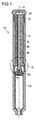
図1、2及び6は、駆動アセンブリを備えた薬物送達デバイス100を示す。好ましくは、薬物送達デバイス100は薬物を注射し得るペン型薬物送達デバイスである。好ましくは、薬物送達デバイス100は固定用量デバイス、特に固定、非使用者変動、例えば一定用量を投薬するデバイスである。薬物送達デバイス100はカートリッジホルダ102に配置される薬物含有カートリッジ101を含む。カートリッジ101は薬物103を保持する。薬物送達デバイス100はニードルデバイス104を更に含む。ニードルデバイス104はカートリッジホルダ102の遠位端に配置され、好ましくはそれに固定される。薬物103はニードルデバイス104を通して投薬され得る。薬物103は、インスリン、成長ホルモン、低分子量ヘパリン、及び/又はそれらのアナログ及び/又は誘導体を含んでよい。薬物103は流体であってよい。
1, 2 and 6 show a
栓105はカートリッジ101の内部に配置される。栓105はカートリッジ101の内部で変位することができる。カートリッジ101に対して遠位方向における栓105の変位は薬物の投薬をもたらす。栓105の動きはピストンロッド50により作動する。ピストンロッドはベアリング70を介して栓105に作用する。好ましくは、ベアリング70はなしで済ませてもよい。
The
薬物含有カートリッジ101の近位端に、駆動アセンブリが配置される。薬物含有カートリッジ101は、好ましくはハウジング10の遠位端でハウジング10に固定される。
A drive assembly is disposed at the proximal end of the drug-containing
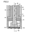
駆動アセンブリはハウジング10を含む。更に駆動アセンブリは駆動部材40及びさらなる駆動部材20を含む。好ましくは、駆動部材40は回転スリーブである。更に、駆動アセンブリはピストンロッド50を含む。加えて、駆動アセンブリは、さらなる駆動部材20とハウジング10の間に配置される付勢部材60を含む。付勢部材60は、薬物の送達中に軸方向においてさらなる駆動部材20に力を加えてよい。好ましくは、付勢部材60は圧縮バネを含む。図5の実施態様で見られるように、駆動アセンブリは、さらなる駆動部材20の望ましくない軸方向運動を防止するために、好ましくはさらなる駆動部材20とハウジング10との間に配置されるスナップイン部材61を含んでよい。
The drive assembly includes a
好ましくは、ハウジング10は近位端11と遠位端12の間で伸びる。ハウジング10は中空シリンダー形状を有してよい。好ましくは、ハウジング10は第1のセクション14及び第2のセクション16を含む。第1のセクション14はスリーブ様の形状を有する。第2のセクション16はディスク様の形状を有する。第2のセクション16は第1のセクション14に固定して連結される。
Preferably, the
ハウジング10は遠位端12に配置される連結手段を含んでよい。遠位端12での連結手段はハウジング10をカートリッジホルダ102と連結するためであってよい。カートリッジホルダ102は第2のセクション16と相互作用する。第2のセクション16は、カートリッジホルダ102の特定位置を得るためにカートリッジホルダ102に対する中間エレメントとして作用する。
The
縦軸Aは近位端11と遠位端12の間で伸びる。縦軸Aは基本的にハウジング10の中心を通して伸びる。ハウジング10の表面は基本的に縦軸Aに沿って伸びる。ハウジング10は、例えば薬物の投薬又は残存用量の数を示し得る表示部を備えるための開口部を含んでよい。
The longitudinal axis A extends between the
さらなる駆動部材20は好ましくは軸方向に伸びている内側ねじ山21を含む(図2)。さらなる駆動部材20の内側ねじ山21は、縦軸A又は縦軸Aと平行な軸であるこの経路の中心軸でラセン経路を従動する。他の実施態様では、回転スリーブはさらなる駆動部材20の係合デバイスと係合する外側ねじ山を有する。さらなる駆動部材20はハウジング10に対して軸方向に変位可能で、それによりねじ山21を介する回転スリーブの回転運動を可能にする。好ましくは回転スリーブに対してさらなる駆動部材20のいずれの軸方向運動も回転スリーブの回転運動に変換される。
The
さらなる駆動部材20は好ましくはハウジング10にスプライン結合される。さらなる駆動部材20は好ましくは軸方向に伸びている少なくとも1つの溝を含む。溝はハウジング10と例えばタブ(tab)と係合している。タブはハウジング10の部材であり、又はハウジング10にロックされる。ハウジング10と係合している溝は、ハウジング10に対して相対的なさらなる駆動部材20の軸方向運動を確実にし得る。他の実施態様では、ハウジング10は溝を含み、そしてさらなる駆動部材20は溝と係合しているタブを有する。
The
さらなる駆動部材20は、好ましくはさらなる駆動部材20を追加エレメントと連結するための連結手段を含む。例えば、用量ボタン24はさらなる駆動部材20に連結される。用量ボタン24は、さらなる駆動部材20に対して遠位又は近位方向において用量ボタン24に加えられる力を伝達し得る。用量ボタン24は、薬物の用量を投与するためにハウジング10に対して遠位方向に押し込まれてよい。用量ボタン24は、薬物の用量を設定するためにハウジング10に対して近位方向に引っ張られてよい。特に、用量ボタン24は付勢部材60の支持により近位方向に引っ張られてよい。別の実施態様では、薬物の用量を投与するための力は直接さらなる駆動部材20に加えられる。本実施態様では、別々の用量ボタン24は必要ではない。その力は使用者により用量ボタン24に手動で加えられる力であってよい。
The
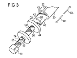
回転スリーブは外面42を有する。外面42は、軸方向に伸びる係合デバイス43を含み、そしてさらなる駆動部材20のねじ山21と係合している。ねじ山21及び係合デバイス43は、回転スリーブの回転運動へさらなる駆動部材20の軸方向運動の変換を可能にする。回転スリーブの回転運動は、第1の方向D1で又は第1の方向D1に対して反時計回りの第2の方向D2で行うことができる(図3)。特に、第1の方向D1における回転スリーブの回転運動は、さらなる駆動部材20の遠位方向運動であるハウジング10に対して遠位方向D3におけるさらなる駆動部材20の動きによって達成することができる。従って、第2の方向D2における回転スリーブの回転運動は、近位方向D4においてハウジング10に対するさらなる駆動部材20の軸方向近位運動によって達成することができる。
The rotating sleeve has an
回転スリーブは更に、半径方向に伸びる突出部44、例えば半径方向に外向きのフランジを含む。突出部44はハウジング10の第1のセクション14と第2のセクション16の間に配置されるので(図3参照)、ハウジング10に対する回転スリーブの軸方向運動を防止し得る。従って、回転スリーブは第1の方向D1及び第2の方向D2においてだけ回転運動を行う。
The rotating sleeve further includes a
駆動部材40は、半径方向に、特にハウジング10の縦軸Aに向いて駆動部材40の内面から突出する案内ピース45を有する。案内ピース45はピストンロッド50と係合している。
The
ピストンロッド50は外面52を有する。案内トラック53はピストンロッド50の外面52に配置される。好ましくは、駆動部材40の案内ピース45は案内トラック53に配置される。好ましくは、案内ピース45は案内トラック53において可動である。案内ピース45及び案内トラック53の係合は駆動部材40とピストンロッド50の間のしっかりしたスロット付き結合を可能にする。
The
好ましくは、案内ピース45は図4及び4Aに示すように円正方形セクションを有する。これは案内トラック53において案内ピース45の滑らかで安定した動きを可能にする。
Preferably, the
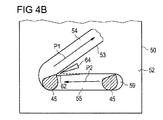
図4は、詳細図においてピストンロッド50の案内トラック53を示す。案内ピース45及び案内トラック53は係合される。案内トラック53は曲がってよいピストンロッド50の外面52に伸びる。回転スリーブ及びピストンロッド50の機能を説明するために、案内トラック53の経路が図4の平面図で示される。案内トラック53は、ピストンロッド50が遠位方向に動くとき、案内ピース45に沿って動き得る。
FIG. 4 shows the
特に、図4、4A及び4Bにおいて見られるように、案内トラック53は好ましくは、ピストンロッド50の外面52上にジグザグ様の線のように形成される。好ましくは、ジグザグ様の線は、特に案内トラック53の範囲の主方向が関係している所まで軸方向に伸びている。
In particular, as seen in FIGS. 4, 4A and 4B, the
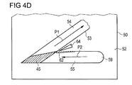
案内トラック53は連続セグメントを有する。案内トラック53の連続セグメントの各々は傾斜セクション54を含む。更に、案内トラック53の連続セグメントの各々は、垂直セクション55を含む。傾斜セクション54の1つ及び垂直セクション55の1つの連続セグメントの各々は、「V」のように形成される。「V」のように形成されるこれらの連続セグメントの一個が図4B、4C及び4Dに示される。
The
垂直セクション55は、縦軸Aに対して便宜的に垂直に又は本質的に垂直に伸びて、そして用量設定セクションとして作用している。案内ピース45は用量設定中に垂直セクション55に移動する。
The
傾斜セクション54は縦軸Aに対して斜めに伸び、用量投薬セクションとして作用している。セグメントのセクション55が軸Aに対して斜めになっている場合、そのセグメントのセクション54は好ましくは軸Aに対して更に斜めである。しかしながら、セクション55は軸Aに対して垂直に伸びることが好ましい。案内ピース45は用量投薬中に傾斜セクション54に移動する。傾斜セクション54は第1の経路P1を画成し、そして垂直セクション55は第2の経路P2を画成する。第1の経路P1及び第2の経路P2は案内ピース45を案内するように設計される。一般的に、傾斜セクション54及び垂直セクション55は案内トラック53に沿って交互に配列され、それにより案内トラック53に対してジグザグの線を形成する。
The
傾斜セクション54は遠位ファイナルエリア56及び近位ファイナルエリア58を有する。傾斜セクション54のピッチのコースは、それが遠位ファイナルエリア56から近位ファイナルエリア58まで減少することになる。それは傾斜セクション54が図4における表示に対して凹面関数を形成することを意味する。好ましくは、傾斜セクション54のピッチは、遠位ファイナルエリア56から近位ファイナルエリア58まで連続的に減少することである。更なる実施態様では、傾斜セクション54のピッチは、遠位ファイナルエリア56と近位ファイナルエリア58との間で制限エリアを減少し得る。
The
好ましくは、ピストンロッド50はハウジング10にスプライン結合される。これは回転なしに軸方向においてピストンロッド50の正確な動きを容易にする。
Preferably, the
図4Aの実施態様では、端面59は図4Aに対して一番上の第2のセクション54の近位端に直接配置される。これは最後の許容用量が投薬された直後に、ピストンロッド50の追加設定動作を早くも防止することを可能にする。図4の実施態様では、後続の用量設定動作が許容され、一方で実施する必要がある後続の用量投薬動作は防止される。
In the embodiment of FIG. 4A, the
図4B及び4Cの実施態様では、案内ピース45はその近位端に傾斜切削を備えた半円正方形セクションを有する。傾斜切削の角度は図4B及び4Cで異なる。傾斜切削は案内トラック53における案内ピース45の滑らかで安定した動きを許容する。
In the embodiment of FIGS. 4B and 4C, the
図4Dの実施態様では、案内ピース45は半円正方形セクションを有する。案内ピース45のこの形状は案内トラック53における案内ピース45の安定した動きを許容する。
In the embodiment of FIG. 4D, the
更に、図4B、4C及び4Dの実施態様では、案内トラック53の第1のセクション55は、垂直セクション55の近位壁から伸びる楔形の突起部62を有する。突起部62は弾性変形可能である。突起部62は断面、特に垂直セクション55の軸方向伸長を減少させる。垂直セクション55は図4B、4C及び4Dの図で右から左の方向に先細りになってよい。突起部62は案内ピース45と機械的協動関係にある。特に楔形の突起部62と組み合わせた図4B、4C及び4Dの案内ピース45の形状は、案内トラック53において案内ピース45の予期せぬ後退を防止し得る。この理由は、案内ピース45が垂直セクション55から傾斜セクション54までのその動作中に突起部62を通過した後に、その上部右エッジを有する案内ピース45の形状及び突起部62の形状は、案内ピース45が傾斜セクション54へスナップし、そしてそれ故傾斜セクション54から垂直セクション55まで戻る案内ピース45の動きを防止する結果になるからである。
Further, in the embodiment of FIGS. 4B, 4C and 4D, the
加えて又は代わりに、図4B、4C及び4Dの実施態様では、凹部64は突起部62に隣接して垂直セクション55と傾斜セクション54の間に配置される。案内ピース45が垂直セクション55から傾斜セクション54までその動作中に突起部62を通過する場合、凹部64は突起部62の可撓性を増加させる。その結果として、垂直セクション55から傾斜セクション54までの案内ピース45の確実な通過が、傾斜セクション54から垂直セクション55まで戻る案内ピース45の動きの阻止を妨害せずに可能である。
In addition or alternatively, in the embodiment of FIGS. 4B, 4C, and 4D, the
下記において、図4の実施態様に記載の駆動アセンブリ及び薬物送達デバイスの機能は詳細に記載される: In the following, the functions of the drive assembly and drug delivery device described in the embodiment of FIG. 4 will be described in detail:
用量ボタン24の作動、好ましくはハウジング10に対して用量ボタン24の手動で作動する動きは、駆動アセンブリの一部であるさらなる駆動部材20の直線変位をもたらす。さらなる駆動部材20は遠位方向に、例えば遠位端12、及びニードルデバイス104に向いてそれぞれ直線的に変位する。さらなる駆動部材20の直線変位は、第1又は第2の方向D1、D2の1つに回転スリーブの回転運動及びピストンロッド50の対応の変位をもたらす。
Actuation of the
用量の設定中に、使用者はスナップインエレメントを除去し、そしてさらなる駆動部材20を近位方向D4に引っ張る。この動きは付勢部材60により支持され得る。ハウジング10に対して近位方向D4におけるさらなる駆動部材20の動きは、第2の方向D2における回転スリーブの回転運動と相関するので、回転スリーブの案内ピース45は、先行傾斜セクション54の近位ファイナルエリア58から後続傾斜セクション54の遠位ファイナルエリア56まで第2の経路P2上で案内トラック53の垂直セクション55に沿って進む(travel)。案内ピース45の動きは案内トラック53を制限している2つの壁により限定される。案内トラック53の本セグメントの垂直セクション55と傾斜セクション54の間で遠位ファイナルエリア56の近くに又はその中において、案内ピース45が案内トラック53の壁、例えば案内トラック53の左の壁と接触するようになるまで、案内ピース45は第2の経路P2に沿って進む。ピストンロッド50は、用量設定工程中にハウジング10に対して軸方向に動くことができない。後続傾斜セクション54の遠位ファイナルエリア56における第2の経路P2の終わりに、用量設定工程は完了する。
During dose setting, the user removes the snap-in element and pulls the
用量を投薬するために、使用者は遠位方向D3において薬物送達デバイス100のさら
なる駆動部材20を押す。遠位方向D3におけるさらなる駆動部材20の動きは、スナップインエレメント61が図5に示されるようにハウジング10と係合するようになるとき終了する。ハウジング10に対する遠位方向D3におけるさらなる駆動部材20の動きは、第1の方向D1における回転スリーブの回転運動と相関するので、回転スリーブの案内ピース45は、遠位ファイナルエリア56から近位ファイナルエリア58まで傾斜セクション54の第1の経路P1に従動する。案内ピース45の動きは案内トラック53を制限している2つの壁によって再度限定される。案内ピース45はここで案内トラック53の壁右と協動する。従って、案内ピース45が、本セグメントの傾斜セクション54と案内トラック53の後続セグメントの垂直セクション55の間で近位ファイナルエリア58に到達するまで、案内ピース45は第1の経路P1に沿って進む。
To dispense the dose, the user pushes the
この動きの間に、ピストンロッド50は、傾斜セクション54の壁と相互作用する案内ピース45のために遠位方向に動く。それにより、薬物103は薬物含有カートリッジ101から投薬し得る。傾斜セクション54のピッチは本傾斜セクション54の遠位ファイナルエリア56から近位ファイナルエリア58まで減少するので、注射の速度は本傾斜セクション54で案内ピース45の移動中に減少する。これにより、用量送達段階の終わりには注射ストレスは減少する。注射された用量の薬物が用量送達段階の終わりに減少するために、薬物の分散期間は減少する。このように、薬物送達デバイスが薬物の投与中に使用者の生物学的組織に残る時間は小さく保たれてよい。更に、用量送達段階の終わりには薬物送達デバイスからの薬物の漏出は防止され得る。用量送達段階中の注射の速度減少のために、射出力が同時に減少し得る。付勢部材60は、さらなる駆動部材20に対して力を及ぼすので、射出力の減少は付勢部材60によって補正され、効果的な射出力は一定に維持され得る。
During this movement, the
前述のように用量を設定及び投薬するサイクルが行われた後、使用者は連続的な工程で前述のように用量を設定し投薬する前述の工程を行ってよい。ここで、回転スリーブの案内ピース45は、傾斜セクション54の1つ及び垂直セクション55の1つを備えた連続セグメントにより案内される。このように、薬物の複数回用量が投薬され得る。
After the dose setting and dosing cycle is performed as described above, the user may perform the aforementioned steps of setting and administering the dose as described above in a continuous process. Here, the
参照番号
10 ハウジング
11 近位端
12 遠位端
14 10の第1のセクション
16 10の第2のセクション
20 さらなる駆動部材
21 ねじ山
24 ボタン
40 駆動部材(回転スリーブ)
42 外面
43 係合デバイス
44 突出部
45 案内ピース
50 ピストンロッド
52 外面
53 案内トラック
54 53の傾斜セクション
55 53の垂直セクション
56 遠位ファイナルエリア
58 近位ファイナルエリア
60 付勢部材
61 スナップイン部材
62 突起部
70 ベアリング
100 薬物送達デバイス
102 薬物含有カートリッジ
103 薬物
104 ニードルデバイス
105 栓
A 縦軸
D1 第1の方向
D2 第2の方向
D3 遠位方向
D4 近位方向
P1, P11 第1の経路
P2, P12 第2の経路
42
A Vertical axis D1 First direction D2 Second direction D3 Distal direction D4 Proximal direction P1, P11 First path P2, P12 Second path
Claims (15)
−駆動部材(40)、及び
−ピストンロッド(50)を含んでなる、薬物送達デバイス(100)用の駆動アセンブリであって、
ピストンロッド(50)はハウジング(10)に対して軸方向に可動であり、ここでピストンロッド(50)は案内トラック(53)を含み、駆動部材(40)は、案内トラック(53)に配列される案内ピース(45)を含み、案内トラック(53)は、縦軸(A)に対して傾斜し、案内ピース(45)が傾斜セクション(54)の遠位ファイナルエリア(56)と傾斜セクション(54)の近位ファイナルエリア(58)との間で傾斜セクション(54)と協動するとき、案内ピース(45)とピストンロッド(50)の間の相対運動中に、薬物の単回プリセット用量を投薬するようにハウジングに対するピストンロッドの変位を規定する少なくとも1つのセクション(54)を含み、そして
少なくとも1つの傾斜セクション(54)のピッチは、遠位ファイナルエリア(56)から近位ファイナルエリア(58)まで変化することを特徴とする、薬物送達デバイス(100)用の駆動アセンブリ。 A housing (10) with a proximal end (11) and a distal end (12) and a longitudinal axis (A) extending between the proximal end (11) and the distal end (12);
A drive assembly for a drug delivery device (100) comprising a drive member (40), and a piston rod (50) comprising:
The piston rod (50) is axially movable relative to the housing (10), wherein the piston rod (50) includes a guide track (53) and the drive member (40) is arranged in the guide track (53). The guide track (53) is inclined with respect to the longitudinal axis (A), the guide piece (45) being inclined to the distal final area (56) and the inclined section of the inclined section (54). A single preset of drug during relative movement between the guide piece (45) and the piston rod (50) when cooperating with the inclined section (54) between the proximal final area (58) of (54) Including at least one section (54) defining displacement of the piston rod relative to the housing to dispense a dose, and of at least one inclined section (54) Drive assembly for drug delivery device (100), characterized in that the pitch varies from the distal final area (56) to the proximal final area (58).
Applications Claiming Priority (3)
| Application Number | Priority Date | Filing Date | Title |
|---|---|---|---|
| EP09178215.1 | 2009-12-07 | ||
| EP09178215 | 2009-12-07 | ||
| PCT/EP2010/068916 WO2011069936A1 (en) | 2009-12-07 | 2010-12-06 | Drive assembly for a drug delivery device and drug delivery device |
Publications (3)
| Publication Number | Publication Date |
|---|---|
| JP2013512744A JP2013512744A (en) | 2013-04-18 |
| JP2013512744A5 JP2013512744A5 (en) | 2014-01-23 |
| JP5816191B2 true JP5816191B2 (en) | 2015-11-18 |
Family
ID=42455318
Family Applications (1)
| Application Number | Title | Priority Date | Filing Date |
|---|---|---|---|
| JP2012542483A Expired - Fee Related JP5816191B2 (en) | 2009-12-07 | 2010-12-06 | Drive assembly for drug delivery device and drug delivery device |
Country Status (11)
| Country | Link |
|---|---|
| US (1) | US9022993B2 (en) |
| EP (1) | EP2509663B1 (en) |
| JP (1) | JP5816191B2 (en) |
| CN (1) | CN102695532B (en) |
| AU (1) | AU2010330033B2 (en) |
| BR (1) | BR112012013767A2 (en) |
| CA (1) | CA2779389A1 (en) |
| DK (1) | DK2509663T3 (en) |
| HK (1) | HK1176898A1 (en) |
| IL (1) | IL220169A (en) |
| WO (1) | WO2011069936A1 (en) |
Families Citing this family (26)
| Publication number | Priority date | Publication date | Assignee | Title |
|---|---|---|---|---|
| ES2314182T3 (en) | 2002-02-11 | 2009-03-16 | Antares Pharma, Inc. | INTRADERMIC INJECTOR. |
| EP1850892B2 (en) | 2005-01-24 | 2023-04-19 | Antares Pharma, Inc. | Prefilled needle assisted syringe jet injector |
| WO2007131013A1 (en) | 2006-05-03 | 2007-11-15 | Antares Pharma, Inc. | Two-stage reconstituting injector |
| US9144648B2 (en) | 2006-05-03 | 2015-09-29 | Antares Pharma, Inc. | Injector with adjustable dosing |
| WO2009114542A1 (en) | 2008-03-10 | 2009-09-17 | Antares Pharma, Inc. | Injector safety device |
| EP2318075B1 (en) | 2008-08-05 | 2019-05-22 | Antares Pharma, Inc. | Multiple dosage injector |
| EP2408493A1 (en) | 2009-03-20 | 2012-01-25 | Antares Pharma, Inc. | Hazardous agent injection system |
| JP5752693B2 (en) * | 2009-09-30 | 2015-07-22 | サノフィ−アベンティス・ドイチュラント・ゲゼルシャフト・ミット・ベシュレンクテル・ハフツング | Assembly and piston rod for a drug delivery device |
| EP2399635A1 (en) | 2010-06-28 | 2011-12-28 | Sanofi-Aventis Deutschland GmbH | Auto-injector |
| WO2012050511A1 (en) * | 2010-10-11 | 2012-04-19 | Shl Group Ab | Medicament delivery device |
| USRE48593E1 (en) | 2010-12-21 | 2021-06-15 | Sanofi-Aventis Deutschland Gmbh | Auto-injector |
| EP2468333A1 (en) | 2010-12-21 | 2012-06-27 | Sanofi-Aventis Deutschland GmbH | Auto-injector |
| RU2603289C2 (en) * | 2011-06-17 | 2016-11-27 | Санофи-Авентис Дойчланд Гмбх | Drug delivery device for introduction of preset drug dose |
| US9220660B2 (en) | 2011-07-15 | 2015-12-29 | Antares Pharma, Inc. | Liquid-transfer adapter beveled spike |
| US8496619B2 (en) | 2011-07-15 | 2013-07-30 | Antares Pharma, Inc. | Injection device with cammed ram assembly |
| US8834449B2 (en) | 2012-01-23 | 2014-09-16 | Ikomed Technologies, Inc. | Mixing syringe |
| US9751056B2 (en) | 2012-01-23 | 2017-09-05 | Merit Medical Systems, Inc. | Mixing syringe |
| PT2822618T (en) | 2012-03-06 | 2024-03-04 | Antares Pharma Inc | Prefilled syringe with breakaway force feature |
| JP6457383B2 (en) | 2012-04-06 | 2019-01-23 | アンタレス・ファーマ・インコーポレーテッド | Needle-assisted jet injection of testosterone composition |
| WO2013169804A1 (en) | 2012-05-07 | 2013-11-14 | Antares Pharma, Inc. | Needle assisted jet injection device having reduced trigger force |
| ES2763633T3 (en) | 2013-02-11 | 2020-05-29 | Antares Pharma Inc | Needle assisted jet injection device having reduced firing force |
| ES2742046T3 (en) | 2013-03-11 | 2020-02-12 | Antares Pharma Inc | Dose injector with pinion system |
| WO2014165136A1 (en) | 2013-03-12 | 2014-10-09 | Antares Pharma, Inc. | Constant volume prefilled syringes and kits thereof |
| EP2823841A1 (en) | 2013-07-09 | 2015-01-14 | Sanofi-Aventis Deutschland GmbH | Autoinjector |
| EP2923714A1 (en) | 2014-03-28 | 2015-09-30 | Sanofi-Aventis Deutschland GmbH | Autoinjector triggered by skin contact |
| US11577028B2 (en) * | 2021-01-20 | 2023-02-14 | Becton, Dickinson And Company | Syringe with a bidirectional plunger advancing mechanism for a micro-dosing syringe pump |
Family Cites Families (8)
| Publication number | Priority date | Publication date | Assignee | Title |
|---|---|---|---|---|
| US4475905A (en) * | 1982-09-30 | 1984-10-09 | Himmelstrup Anders B | Injection device |
| US5256152A (en) * | 1991-10-29 | 1993-10-26 | Marks Lloyd A | Safety needle and method of using same |
| GB9300567D0 (en) * | 1993-01-12 | 1993-03-03 | Owen Mumford Ltd | Improvements relating to devices for generating intermittent motion |
| DE19822031C2 (en) | 1998-05-15 | 2000-03-23 | Disetronic Licensing Ag | Auto injection device |
| SE9901366D0 (en) * | 1999-04-16 | 1999-04-16 | Pharmacia & Upjohn Ab | Injector device and method for its operation |
| US9486581B2 (en) * | 2002-09-11 | 2016-11-08 | Becton, Dickinson And Company | Injector device with force lock-out and injection rate limiting mechanisms |
| WO2009080775A1 (en) * | 2007-12-20 | 2009-07-02 | Novo Nordisk A/S | Injection device for delivering a fixed dose of liquid drug |
| GB0808389D0 (en) | 2008-05-09 | 2008-06-18 | Owen Mumford Ltd | Electrically actuated injector |
-
2010
- 2010-12-06 BR BR112012013767A patent/BR112012013767A2/en not_active IP Right Cessation
- 2010-12-06 CA CA2779389A patent/CA2779389A1/en not_active Abandoned
- 2010-12-06 DK DK10800903.6T patent/DK2509663T3/en active
- 2010-12-06 CN CN201080060957.5A patent/CN102695532B/en not_active Expired - Fee Related
- 2010-12-06 EP EP10800903.6A patent/EP2509663B1/en active Active
- 2010-12-06 JP JP2012542483A patent/JP5816191B2/en not_active Expired - Fee Related
- 2010-12-06 US US13/509,602 patent/US9022993B2/en active Active
- 2010-12-06 AU AU2010330033A patent/AU2010330033B2/en not_active Ceased
- 2010-12-06 WO PCT/EP2010/068916 patent/WO2011069936A1/en active Application Filing
-
2012
- 2012-06-04 IL IL220169A patent/IL220169A/en not_active IP Right Cessation
-
2013
- 2013-04-15 HK HK13104516.2A patent/HK1176898A1/en not_active IP Right Cessation
Also Published As
| Publication number | Publication date |
|---|---|
| DK2509663T3 (en) | 2015-04-27 |
| IL220169A (en) | 2014-06-30 |
| CN102695532A (en) | 2012-09-26 |
| CA2779389A1 (en) | 2011-06-16 |
| JP2013512744A (en) | 2013-04-18 |
| IL220169A0 (en) | 2012-07-31 |
| EP2509663A1 (en) | 2012-10-17 |
| CN102695532B (en) | 2015-02-18 |
| AU2010330033B2 (en) | 2014-10-23 |
| HK1176898A1 (en) | 2013-08-09 |
| US9022993B2 (en) | 2015-05-05 |
| US20130018327A1 (en) | 2013-01-17 |
| EP2509663B1 (en) | 2015-01-21 |
| WO2011069936A1 (en) | 2011-06-16 |
| BR112012013767A2 (en) | 2016-04-26 |
| AU2010330033A1 (en) | 2012-06-21 |
Similar Documents
| Publication | Publication Date | Title |
|---|---|---|
| JP5816191B2 (en) | Drive assembly for drug delivery device and drug delivery device | |
| JP5830027B2 (en) | Drive assembly for drug delivery device and drug delivery device | |
| JP5752693B2 (en) | Assembly and piston rod for a drug delivery device | |
| JP5851402B2 (en) | Drive mechanism for drug delivery device and drug delivery device | |
| JP5775534B2 (en) | Assembly for drug delivery device and drug delivery device | |
| JP5722332B2 (en) | Drive mechanism for a drug delivery device | |
| JP5668058B2 (en) | Assembly for drug delivery device and drug delivery device | |
| JP6076534B2 (en) | Drive assembly, drive component and drug delivery device | |
| JP2013505094A (en) | Assembly and indicator for a drug delivery device | |
| JP2012532722A (en) | Drive assembly for pen-type syringe and pen-type syringe with drive assembly | |
| JP5749724B2 (en) | Drug delivery device assembly | |
| JP6012608B2 (en) | Drive mechanism for drug delivery device and drug delivery device | |
| JP5886748B2 (en) | Assembly of drug delivery device | |
| JP6042338B2 (en) | Drive mechanism for drug delivery device and drug delivery device | |
| JP6042339B2 (en) | Drive mechanism for drug delivery device and drug delivery device |
Legal Events
| Date | Code | Title | Description |
|---|---|---|---|
| A521 | Request for written amendment filed |
Free format text: JAPANESE INTERMEDIATE CODE: A523 Effective date: 20131127 |
|
| A621 | Written request for application examination |
Free format text: JAPANESE INTERMEDIATE CODE: A621 Effective date: 20131127 |
|
| A977 | Report on retrieval |
Free format text: JAPANESE INTERMEDIATE CODE: A971007 Effective date: 20140829 |
|
| A131 | Notification of reasons for refusal |
Free format text: JAPANESE INTERMEDIATE CODE: A131 Effective date: 20140902 |
|
| A131 | Notification of reasons for refusal |
Free format text: JAPANESE INTERMEDIATE CODE: A131 Effective date: 20150519 |
|
| A521 | Request for written amendment filed |
Free format text: JAPANESE INTERMEDIATE CODE: A523 Effective date: 20150814 |
|
| TRDD | Decision of grant or rejection written | ||
| A01 | Written decision to grant a patent or to grant a registration (utility model) |
Free format text: JAPANESE INTERMEDIATE CODE: A01 Effective date: 20150908 |
|
| A61 | First payment of annual fees (during grant procedure) |
Free format text: JAPANESE INTERMEDIATE CODE: A61 Effective date: 20150925 |
|
| R150 | Certificate of patent or registration of utility model |
Ref document number: 5816191 Country of ref document: JP Free format text: JAPANESE INTERMEDIATE CODE: R150 |
|
| LAPS | Cancellation because of no payment of annual fees |