JP5815975B2 - Database apparatus and database reorganization method - Google Patents
Database apparatus and database reorganization method Download PDFInfo
- Publication number
- JP5815975B2 JP5815975B2 JP2011091583A JP2011091583A JP5815975B2 JP 5815975 B2 JP5815975 B2 JP 5815975B2 JP 2011091583 A JP2011091583 A JP 2011091583A JP 2011091583 A JP2011091583 A JP 2011091583A JP 5815975 B2 JP5815975 B2 JP 5815975B2
- Authority
- JP
- Japan
- Prior art keywords
- update
- database
- storage unit
- copy
- update log
- Prior art date
- Legal status (The legal status is an assumption and is not a legal conclusion. Google has not performed a legal analysis and makes no representation as to the accuracy of the status listed.)
- Active
Links
Images


Landscapes
- Information Retrieval, Db Structures And Fs Structures Therefor (AREA)
Description
本発明の実施形態は、データベース装置およびデータベース再編成方法に関する。 Embodiments described herein relate generally to a database apparatus and a database reorganization method.
記憶装置により構成されるデータベース(DB)は、データの更新と削除が繰り返されることにより、断片化した未使用領域が生まれ処理効率が低下してしまう場合がある。この場合、レコードと未使用領域の順番、配置を変更する(再編成する)ことにより、データベースの処理効率を回復させることができる。また、再編成は、断片化したデータベース(オリジナルDB)の内容を他のボリュームにコピーしてコピーDBを作成し、このコピーDBを利用して行ってもよい。 In a database (DB) configured by a storage device, repeated update and deletion of data may result in a fragmented unused area and lower processing efficiency. In this case, the database processing efficiency can be recovered by changing (reorganizing) the order and arrangement of records and unused areas. Further, the reorganization may be performed by copying the contents of the fragmented database (original DB) to another volume to create a copy DB and using this copy DB.
コピーDBを利用する場合、オリジナルDBとコピーDBとの内容を一致させることが重要である。オリジナルDBとコピーDBとの内容を一致させるためには、たとえばオリジナルDBからコピーDBへデータをコピーし、コピーDBの再編成が終了した後、コピー開始からオリジナルDBに対する更新禁止までの期間にオリジナルDBに対して行われた更新処理を更新ログファイルに記録された更新ログをもとにコピーDBに再現する(同期する)方法が考えられる。 When using the copy DB, it is important to match the contents of the original DB and the copy DB. In order to make the contents of the original DB and the copy DB coincide with each other, for example, data is copied from the original DB to the copy DB. A method of reproducing (synchronizing) the update process performed on the DB in the copy DB based on the update log recorded in the update log file is conceivable.
しかし、オリジナルDBとコピーDBとの内容を一致させるためには、コピー、再編成および同期からなる一連の処理(以下、再編成処理という)の全ての期間または一部の期間において、オリジナルDBに対する更新を禁止してオリジナルDBのデータ内容を凍結させ、この更新禁止期間内に内容の一致を図ることが多い。この場合、更新禁止期間が長いと、各種アプリケーションプログラムは、データの更新や参照などのデータベースアクセスを妨害される期間が長くなってしまい、利便性が悪くなってしまう。 However, in order to make the contents of the original DB and the copy DB coincide with each other, in the entire period or a part of a series of processes including copy, reorganization, and synchronization (hereinafter referred to as reorganization process), In many cases, updating is prohibited to freeze the data contents of the original DB, and the contents are matched within the update prohibition period. In this case, if the update prohibition period is long, various application programs have a longer period during which database access such as data update or reference is obstructed, resulting in poor convenience.
また、オリジナルDBとコピーDBとの内容を一致させるためにコピー中に並行して同期を行うと、コピー処理と同期処理とでコピーDB内データのWRITEロックを取り合ってしまう場合があり、この場合も各種アプリケーションプログラムはデータベースアクセスを妨害されてしまい、利便性が悪くなってしまう。 In addition, if synchronization is performed in parallel during copying in order to make the contents of the original DB and the copy DB coincide with each other, the WRITE lock of the data in the copy DB may be held between the copy process and the synchronization process. However, various application programs are prevented from accessing the database, and the convenience is deteriorated.
本発明の一実施形態に係るデータベース装置は、上述した課題を解決するために、コピー
部と、進捗情報記憶部と、アクセス先決定部と、初期同期部と、最終同期部と、再編成部
と、を備える。コピー部は、第1のボリュームに格納された元データベースのデータをコ
ピーして第2のボリュームにコピーデータベースを作成する。進捗情報記憶部は、コピー
、再編成および同期からなる一連の処理の進捗状況を示す状態フラグを記憶する。アクセ
ス先決定部は、状態フラグがコピー中もしくはコピー後の同期中を示す値であると、元デ
ータベースをアプリケーションプログラムのアクセス先とし、アプリケーションプログラ
ムにより元データベースのデータのうちコピー中またはコピー済みのデータが更新される
ごとに、更新後の値の情報および更新されたデータを識別するための情報を含む更新ログ
を更新ログ記憶部に記憶させる。また、アクセス先決定部は、状態フラグが再編成中もし
くは再編成後の同期中を示す値であると、コピーデータベースをアプリケーションプログ
ラムのアクセス先とし、アプリケーションプログラムによりコピーデータベースのデータ
が更新されるごとに、更新ログを更新ログ記憶部に記憶させる。また、アクセス先決定部
は、状態フラグがアプリケーションプログラムのアクセス先を元データベースに切り替え
中であると示す値であると、元データベースをアプリケーションプログラムのアクセス先
とし、状態フラグを通常状態を示す値とする。
初期同期部は、コピー部によるコピーデータベースの作成が終わり、かつ更新ログ記憶部
に記憶された更新ログの数が閾値より多いと、元データベースの排他ロックを取得せず、
アプリケーションプログラムによる元データベースのデータの更新が許可され更新に応じ
たアクセス先決定部による更新ログの生成が継続されたまま、更新ログ記憶部に記憶され
た更新ログを1つずつコピーデータベースに適用するとともに適用した更新ログを更新ロ
グ記憶部から削除する処理を更新ログ記憶部に記憶された更新ログの数が閾値以下となる
まで繰り返す。また、初期同期部は、元データベースの再編成が終わり、かつ更新ログ記
憶部に記憶された更新ログの数が閾値より多いと、コピーデータベースの排他ロックを取
得せずに更新ログ記憶部に記憶された更新ログを1つずつ元データベースに適用するとと
もに適用後の更新ログを更新ログ記憶部から削除する処理を更新ログ記憶部に記憶された
更新ログの数が閾値以下となるまで繰り返す。最終同期部は、コピー部によるコピーデー
タベースの作成が終わり、かつ更新ログ記憶部に記憶された更新ログの数が閾値以下であ
ると、元データベースの排他ロックを取得して元データベースのデータに対する更新およ
び参照を禁止し、更新ログ記憶部に記憶された更新ログを1つずつコピーデータベースに
適用するとともに適用後の更新ログを更新ログ記憶部から削除し、更新ログ記憶部に記憶
された更新ログの数がゼロになると、元データベースの排他ロックを開放することにより
、元データベースとコピー部により作成されたコピーデータベースとを同期するとともに
、状態フラグを、アプリケーションプログラムのアクセス先をコピーデータベースに切り
替え中であると示す値に更新する。また、最終同期部は、元データベースの再編成が終わ
り、かつ更新ログ記憶部に記憶された更新ログの数が閾値以下であると、コピーデータベ
ースの排他ロックを取得して更新ログ記憶部に記憶された更新ログを1つずつ元データベ
ースに適用するとともに適用後の更新ログを更新ログ記憶部から削除し、更新ログ記憶部
に記憶された更新ログの数がゼロになると、コピーデータベースの排他ロックを開放する
ことにより、コピーデータベースと再編成部により再編成された元データベースとを同期
するとともに、状態フラグを、アプリケーションプログラムのアクセス先を元データベー
スに切り替え中であると示す値に更新する。再編成部は、元データベースとコピー部によ
り作成されたコピーデータベースとが最終同期部により同期され、アクセス先決定部によ
り状態フラグに基づいてアプリケーションプログラムのアクセス先がコピーデータベース
に切り替えられるとともに状態フラグが再編成中もしくは再編成後の同期中を示す値に更
新されると、元データベースを再編成する。
In order to solve the above-described problem, a database device according to an embodiment of the present invention includes a copy unit, a progress information storage unit, an access destination determination unit, an initial synchronization unit, a final synchronization unit, and a reorganization unit. And comprising. The copy unit copies the original database data stored in the first volume to create a copy database in the second volume. The progress information storage unit stores a status flag indicating a progress status of a series of processes including copying, reorganization, and synchronization. If the status flag is a value indicating that the status flag is being copied or being synchronized after copying, the access destination determination unit sets the original database as the access destination of the application program, and the application program copies data that has been copied or has been copied. Each time is updated, an update log including information on the updated value and information for identifying the updated data is stored in the update log storage unit. In addition, the access destination determination unit sets the copy database as the access destination of the application program and updates the copy database data by the application program when the status flag is a value indicating that the reorganization or the synchronization after the reorganization is in progress. The update log is stored in the update log storage unit. Further, when the status flag is a value indicating that the access destination of the application program is being switched to the original database, the access destination determination unit sets the original database as the access destination of the application program and sets the status flag as a value indicating the normal state. To do.
When the initial synchronization unit finishes creating the copy database by the copy unit and the number of update logs stored in the update log storage unit is larger than the threshold, the initial synchronization unit does not acquire the exclusive lock of the original database,
The update log stored in the update log storage unit is applied to the copy database one by one while the update of the original database is permitted by the application program and the update log generation by the access destination determination unit corresponding to the update is continued. The process of deleting the applied update log from the update log storage unit is repeated until the number of update logs stored in the update log storage unit is equal to or less than the threshold. In addition, when the reorganization of the original database is completed and the number of update logs stored in the update log storage unit is larger than the threshold, the initial synchronization unit stores the copy database in the update log storage unit without acquiring an exclusive lock. The applied update logs are applied to the original database one by one and the process of deleting the applied update logs from the update log storage unit is repeated until the number of update logs stored in the update log storage unit is equal to or less than the threshold. The final synchronization unit acquires an exclusive lock of the original database and updates the data of the original database when the creation of the copy database by the copy unit is finished and the number of update logs stored in the update log storage unit is less than or equal to the threshold value The update log stored in the update log storage unit is prohibited, the reference is prohibited, the update logs stored in the update log storage unit are applied to the copy database one by one and the applied update log is deleted from the update log storage unit. When the number of files reaches zero, the original database and the copy database created by the copy unit are synchronized by releasing the exclusive lock on the original database, and the status flag is being switched to the copy database for the application program access destination. The value is updated to indicate that it is. The final synchronization unit acquires an exclusive lock of the copy database and stores it in the update log storage unit when the reorganization of the original database is completed and the number of update logs stored in the update log storage unit is equal to or less than the threshold value. The applied update logs are applied to the original database one by one and the applied update logs are deleted from the update log storage unit. When the number of update logs stored in the update log storage unit becomes zero, the exclusive lock of the copy database Is released, the copy database and the original database reorganized by the reorganization unit are synchronized, and the status flag is updated to a value indicating that the access destination of the application program is being switched to the original database. Reorganizing unit includes a copy database created by the source database and the copy unit is synchronized by the last synchronization unit, the state flag with the access destination of the application program based on the state flag by access destination determining unit is switched to the copy database Is updated to a value indicating that reorganization or synchronization after reorganization is performed, the original database is reorganized.
本発明に係るデータベース装置およびデータベース再編成方法の実施の形態について、添付図面を参照して説明する。 Embodiments of a database apparatus and a database reorganization method according to the present invention will be described with reference to the accompanying drawings.
(第1の実施形態)
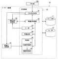
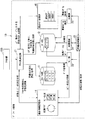
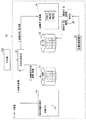
図1は、本発明の第1実施形態に係るデータベース装置10の一例を示す全体構成図である。また、図2は、本発明の第1実施形態に係るデータベース装置10により実行される再編成処理全体における各構成要件間の関係を簡単に示す説明図である。
(First embodiment)
FIG. 1 is an overall configuration diagram showing an example of a
本実施形態では、オリジナルデータベース(以下、オリジナルDBという)がコピーデータベース(以下、コピーDBという)にコピーされ、コピー開始後にオリジナルDBになされた更新内容をコピーDBに適用して互いを同期した後、コピーDBが再編成される場合の例について説明する。 In the present embodiment, after an original database (hereinafter referred to as an original DB) is copied to a copy database (hereinafter referred to as a copy DB), the updated contents made in the original DB after the start of copying are applied to the copy DB and synchronized with each other. An example when the copy DB is reorganized will be described.
データベース装置10は、図1に示すように、第1のボリュームに格納されたオリジナルDB11、第2のボリュームに格納されたコピーDB12、再編成処理を制御する主制御部13、進捗情報記憶部14、および更新ログ記憶部15を有する。
As shown in FIG. 1, the
主制御部13のCPUは、ROMをはじめとする記憶媒体に記憶された再編成処理プログラムおよびこのプログラムの実行のために必要なデータをRAMへロードし、このプログラムに従って、アプリケーションプログラムによるデータベースアクセスに対する妨害を低減しつつ確実にデータベースの再編成処理を行う処理を実行する。
The CPU of the
主制御部13のRAMは、CPUが実行するプログラムおよびデータを一時的に格納するワークエリアを提供する。
The RAM of the
主制御部13のROMをはじめとする記憶媒体は、再編成処理プログラムや、これらのプログラムを実行するために必要な各種データを記憶する。
The storage medium such as the ROM of the
なお、ROMをはじめとする記憶媒体は、磁気的もしくは光学的記録媒体または半導体メモリなどの、CPUにより読み取り可能な記録媒体を含んだ構成を有し、これら記憶媒体内のプログラムおよびデータの一部または全部は電子ネットワークを介してダウンロードされるように構成してもよい。また、進捗情報記憶部14および更新ログ記憶部15は、主制御部13のRAMやROMの一部領域に設けられてもよい。
A storage medium such as a ROM has a configuration including a recording medium readable by a CPU, such as a magnetic or optical recording medium or a semiconductor memory, and a part of programs and data in the storage medium. Or you may comprise so that all may be downloaded via an electronic network. Further, the progress
図1に示すように、主制御部13のCPUは、再編成処理プログラムによって、少なくともアクセス先決定部21、再編成制御部22、コピー部23、再編成部24および同期部25として機能する。この各部21〜25は、RAMの所要のワークエリアをデータの一時的な格納場所として利用する。
As shown in FIG. 1, the CPU of the
アクセス先決定部21は、各種アプリケーションプログラムのデータベースアクセス要求を行う機能実現部としてのアクセス部100からデータの更新要求および参照要求を受けると、進捗情報記憶部14に記憶された状態フラグおよびコピー状況の情報を取得し、この状態フラグおよびコピー状況に応じてアクセス部100のアクセス先をオリジナルDB11およびコピーDB12のいずれか一方に決定する。また、アクセス先決定部21は、再編成処理の最後にアクセス先を切り替える際に、状態フラグを変更する。
When the access
また、アクセス先決定部21は、オリジナルDB11のデータのうちコピー中またはコピー済みのデータが更新されるごとに、更新後の値の情報および更新されたデータを識別するための情報を含む更新ログを更新ログ記憶部15に記憶させる。更新ログとしては、更新後の値と更新されたデータを識別するための情報が内容とされればよく、これらを直接に示す情報やSQL文などを用いることができる。
The access
なお、SQL文を用いる場合は、SQL文に第3のデータベースの情報が含まれていないことが好ましい。たとえば第3のデータベースのデータの値を参照するようになっているSQL文など、SQL文に第3のデータベースの情報が含まれている場合、オリジナルDB11の更新時点とコピーDB12への更新ログ適用時点とで第3のデータベースが変化してしまっている可能性があり、オリジナルDB11で行われた更新をコピーDB12で再現することが難しくなるためである。
In addition, when using a SQL sentence, it is preferable that the information of a 3rd database is not contained in a SQL sentence. For example, when the SQL statement includes the information of the third database, such as an SQL statement that refers to the value of the data in the third database, the update point of the
また、データを識別するための情報は、データを特定できる情報であって、テーブル内の位置情報などの物理的な位置情報に限られず、論理アドレスを用いてもよいし、各データにIDが付与されている場合はこのIDを用いてもよい。 The information for identifying the data is information that can identify the data, and is not limited to physical position information such as position information in the table. A logical address may be used, and each data has an ID. If given, this ID may be used.
なお、以下の説明では、コピー中およびコピー済みを総称して「コピー済み」といい、「コピー済み」にはコピーが開始され現在コピー中である状態が含まれるものとする。 In the following description, copying and copying are collectively referred to as “copied”, and “copied” includes a state where copying is started and currently being copied.
再編成制御部22は、アクセス先決定部21、コピー部23、再編成部24および同期部25を制御することにより再編成処理を制御し、進捗情報記憶部14に記憶された状態フラグを更新および取得する。
The
コピー部23は、再編成制御部22により制御され、オリジナルDB11のデータをページごとにコピーしてコピーDB12を作成する。コピー部23は、コピーを開始したページについて、進捗情報記憶部14に記憶されたコピー状況を、未コピーを示す情報からコピー済みを示す情報に更新する。
The
再編成部24は、再編成制御部22により制御され、オリジナルDB11とコピーDB12とが同期部25の最終同期部32により同期されると、オリジナルDB11とコピーDB12とのいずれかを再編成する。本実施形態では、再編成部24がコピーDB12を再編成する場合の例について説明する。
The
同期部25は、初期同期部31および最終同期部32を有する。
The
初期同期部31は、再編成制御部22により制御され、コピー部23によるコピーDB12の作成が終わり、かつ更新ログ記憶部15に記憶された更新ログの数が閾値より多いと、オリジナルDB11の排他ロックを取得せず、更新ログ記憶部15に記憶された更新ログを1つずつコピーDB12に適用するとともに、適用した更新ログを更新ログ記憶部15から削除する。この処理は、更新ログ記憶部15に記憶された更新ログの数が閾値以下となるまで繰り返される。ここで、排他ロックとは、更新アクセスおよび参照アクセスを禁止するロックである。
The
また、初期同期部31は、再編成部24によるコピーDB12の再編成が終わり、かつ更新ログ記憶部15に記憶された更新ログの数が閾値より多いときも同様に、オリジナルDB11の排他ロックを取得せず、更新ログ記憶部15に記憶された更新ログを1つずつコピーDB12に適用するとともに、適用した更新ログを更新ログ記憶部15から削除する。この処理は、更新ログ記憶部15に記憶された更新ログの数が閾値以下となるまで繰り返される。排他ロックが取得されていないため、初期同期部31の処理中は、アクセス部100によるオリジナルDBのデータの更新が許可され、更新に応じたアクセス先決定部21による更新ログの生成は継続される。すなわち、最終同期部32が排他ロックを取得するまでは、初期同期部31の処理中を含め、更新ログ記憶部15に新たな更新ログが追記され続ける。
Similarly, when the reorganization of the
最終同期部32は、再編成制御部22により制御され、コピー部23によるコピーDB12の作成が終わり、かつ更新ログ記憶部15に記憶された更新ログの数が閾値以下であると、オリジナルDB11の排他ロックを取得してオリジナルDB11のデータに対する更新および参照を禁止し、更新ログ記憶部15に記憶された更新ログを1つずつコピーDB12に適用するとともに、適用した更新ログを更新ログ記憶部15から削除する。そして、更新ログ記憶部15に記憶された更新ログの数がゼロになると、最終同期部32は、オリジナルDB11の排他ロックを開放する。この結果、オリジナルDB11とコピーDB12とのコピー後の同期が終了する。
The
また、最終同期部32は、再編成部24によるコピーDB12の再編成が終わり、かつ更新ログ記憶部15に記憶された更新ログの数が閾値以下であるときも同様に、オリジナルDB11の排他ロックを取得してオリジナルDB11のデータに対する更新および参照を禁止し、更新ログ記憶部15に記憶された更新ログを1つずつコピーDB12に適用するとともに、適用した更新ログを更新ログ記憶部15から削除する。そして、更新ログ記憶部15に記憶された更新ログの数がゼロになると、最終同期部32は、オリジナルDB11の排他ロックを開放する。この結果、オリジナルDB11とコピーDB12との再編成後の同期が終了する。
Similarly, when the reorganization of the
なお、初期同期部31が用いる閾値は、ゼロであってもよい。この場合、最終同期部32は、更新ログ記憶部15に記憶された更新ログがゼロになるまで初期同期部31が更新ログを適用した後、最終同期部32がオリジナルDB11の排他ロックを取得するまでの間に、新たに更新ログ記憶部15に追記された更新ログのみを適用することになる。
Note that the threshold used by the
次に、本実施形態に係るデータベース装置10の動作の一例について説明する。
Next, an example of the operation of the
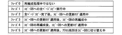
図3は、第1実施形態に係る再編成処理を進捗に応じて複数の処理フェーズに分類する一例を示す説明図である。また、図4は、第1実施形態に係る再編成処理における処理フェーズ、状態フラグ、アクセス先決定部21の動作および再編成制御部22の動作の関係を示す説明図である。
FIG. 3 is an explanatory diagram illustrating an example of classifying the reorganization process according to the first embodiment into a plurality of process phases according to progress. FIG. 4 is an explanatory diagram showing the relationship among the processing phase, status flag, operation of the access
図3および図4に示すように、本実施形態に係る再編成処理は6つのフェーズに分類される。フェーズ0は、再編成処理中ではなく、通常の起動状態である。オリジナルDB11からコピーDB12へページごとのコピーがコピー部23により実行されている期間はフェーズ1に分類される。全ページのコピーが一通り完了した後、同期部25によりコピーDB12に対してフェーズ1開始以降に生成された更新ログが適用されている期間はフェーズ2に分類される。コピーDB12に更新ログが適用された後、再編成部24によりコピーDB12が再編成されている期間はフェーズ3に分類される。コピーDB12が再編成された後、同期部25によりコピーDB12に対してフェーズ3開始以降に生成された更新ログが適用されている期間はフェーズ4に分類される。コピーDB12に更新ログが適用された後、アクセス先決定部21によりアクセス先がコピーDB12へ切り替えられる期間はフェーズ5に分類される。
As shown in FIGS. 3 and 4, the reorganization processing according to the present embodiment is classified into six phases. Phase 0 is not a reorganization process but is a normal activation state. The period during which copying for each page from the
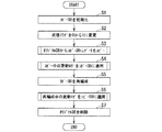
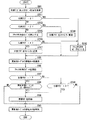
図5は、図1に示すデータベース装置10の主制御部13により、コピーDB12を再編成する場合においてアプリケーションプログラムによるデータベースアクセスに対する妨害を低減しつつ確実にデータベースの再編成処理を行う際の手順を示すフローチャートである。図5において、Sに数字を付した符号は、フローチャートの各ステップを示す。
FIG. 5 shows a procedure for reliably performing database reorganization processing while reducing interference with database access by an application program when the
この手順は、再編成処理の開始指示があった時点でスタートとなる。なお、再編成処理の開始指示は、データベースユーザによって図示しない入力部を介して与えられてもよいし、あらかじめ設定された所定の時間や所定の周期で自動的に与えられてもよい。 This procedure starts when there is an instruction to start the reorganization process. The reorganization process start instruction may be given by the database user via an input unit (not shown), or may be automatically given at a predetermined time or a predetermined cycle.
まず、ステップS1において、コピー部23は、コピーDB12を初期化する。
First, in step S1, the
次に、ステップS2において、再編成制御部22は、進捗情報記憶部14に記憶された状態フラグを0から1に更新する。すなわち、処理フェーズは0から1に移行する。
Next, in step S2, the
次に、ステップS3において、コピー部23は、オリジナルDB11からコピーDB12にページごとにデータをコピーする。このコピーの間、オリジナルDB11に対する更新アクセスは禁止されず、更新ログが更新ログ記憶部15に追記されていく。
Next, in step S3, the
次に、ステップS4において、同期部25は、ステップS3の間にオリジナルDB11に対して行われた更新をコピーDB12に適用してオリジナルDB11とコピーDB12との同期を行う。また、同期部25は、この同期処理の間に行われた更新についてもコピーDB12に適用し、オリジナルDB11とコピーDB12との同期を行う。
Next, in step S4, the
次に、ステップS5において、再編成部24は、コピーDB12を再編成する。この再編成の間にも、オリジナルDB11に対する更新アクセスは禁止されず、更新ログが更新ログ記憶部15に追記されていく。
Next, in step S5, the
次に、ステップS6において、同期部25は、ステップS5の間にオリジナルDB11に対して行われた更新をコピーDB12に適用してオリジナルDB11とコピーDB12との同期を行う。また、同期部25は、この同期処理の間に行われた更新についてもコピーDB12に適用し、オリジナルDB11とコピーDB12との同期を行う。そして、アクセス先決定部21は、アクセス部100のアクセス先をオリジナルDB11からコピーDB12に変更する。
Next, in step S6, the
次に、ステップS7において、再編成制御部22は、コピー部23を介してオリジナルDB11を削除する。この結果、これ以降はコピーDB12がオリジナルのデータベースとして機能する。
Next, in step S <b> 7, the
以上の手順により、コピーDB12を再編成する場合においてアプリケーションプログラムによるデータベースアクセスに対する妨害を低減しつつ確実にデータベースの再編成処理を行うことができる。
According to the above procedure, when the
続いて、オリジナルDB11からコピーDB12にページごとにデータをコピーする際の手順を説明する。
Next, a procedure for copying data for each page from the
図6は、図5のステップS3で主制御部13により実行されるコピーの手順を示すサブルーチンフローチャートである。図6において、Sに数字を付した符号は、フローチャートの各ステップを示す。また、図7は、図6の手順で実行されるコピーの様子を説明するための簡略的なブロック図である。
FIG. 6 is a subroutine flowchart showing the copy procedure executed by the
この手順は、図5のステップS2で処理フェーズが0から1に移行した時点でスタートとなる。 This procedure starts when the processing phase shifts from 0 to 1 in step S2 of FIG.
ステップS31において、コピー部23は、これからコピーしようとしているページが属するテーブル(コピー対象テーブル)の共有ロックを獲得する。共有ロックは、更新アクセスを禁止する一方、参照アクセスを許可するロックである。
In step S31, the
次に、コピー部23は、オリジナルDB11から単位ページ量のデータを取得し(ステップS32)、進捗情報記憶部14に対して書込みを行い取得したページのコピー状況をコピー済みに更新して(ステップS33)、コピー対象テーブルの共有ロックを開放する(ステップS34)。
Next, the
次に、コピー部23は、取得したデータをコピーDB12にコピーし(ステップS35)、オリジナルDB11の全てのページがコピーされたか否かを判定する(ステップS36)。全てのページがコピーされた場合、処理フェーズは1から2に移行し、図5のステップS4に進む。なお、このとき状態フラグは1のままである(図4参照)。一方、未コピーのページがある場合、ステップS31に戻り、引き続き未コピーページのコピーを行う。
Next, the
以上の手順により、オリジナルDB11からコピーDB12にページごとにデータをコピーすることができる。
With the above procedure, data can be copied for each page from the
続いて、コピー後にコピーDB12に更新ログを適用してオリジナルDB11とコピーDB12との同期を行う際の手順を説明する。
Next, a procedure for synchronizing the
図8は、図5のステップS4で主制御部13により実行されるコピー後の同期の手順を示すサブルーチンフローチャートである。図8において、Sに数字を付した符号は、フローチャートの各ステップを示す。また、図9は、図8の手順で実行されるコピー後の同期の様子を説明するための簡略的なブロック図である。
FIG. 8 is a subroutine flowchart showing the post-copying synchronization procedure executed by the
この手順は、図5のステップS3(図6のステップS36のYES)で処理フェーズが1から2に移行した時点でスタートとなる。 This procedure starts when the processing phase shifts from 1 to 2 in step S3 in FIG. 5 (YES in step S36 in FIG. 6).
ステップS41において、同期部25の初期同期部31は、更新ログ記憶部15を検索し、更新ログ記憶部15に記憶された更新ログの数が閾値以下であるか否かを判定する。たとえば、閾値がゼロである場合は、初期同期部31は、更新ログ記憶部15に記憶された更新ログの数がゼロ以下か、すなわちゼロであるか否かを判定する。
In step S41, the
閾値より多い場合は(ステップS41のNO)、初期同期部31は、更新ログ記憶部15から更新ログを1つ取得し(ステップS42)、取得した更新ログをコピーDB12に適用して(ステップS43)、ステップS41に戻る。
When the number is larger than the threshold (NO in step S41), the
一方、閾値以下である場合は(ステップS41のYES)、最終同期部32は、まず、オリジナルDB11の排他ロックを取得してから(ステップS44)、更新ログ記憶部15を検索し、更新ログ記憶部15に記憶された更新ログの数がゼロであるか否かを判定する(ステップS45)。なお、ステップS41において閾値がゼロである場合でも、ステップS41で更新ログ数がゼロであると判定した後にステップS44で最終同期部32がオリジナルDB11の排他ロックを取得するまでの間に新たな更新ログが追記される場合があることに注意する。
On the other hand, if it is equal to or less than the threshold (YES in step S41), the
更新ログ数がゼロでない場合は(ステップS45のNO)、最終同期部32は、更新ログ記憶部15から更新ログを1つ取得し(ステップS46)、取得した更新ログをコピーDB12に適用して(ステップS47)、ステップS45に戻る。
If the number of update logs is not zero (NO in step S45), the
一方、更新ログ数がゼロである場合は(ステップS45のYES)、最終同期部32は、進捗情報記憶部14に記憶された状態フラグを1から2に更新する(ステップS48)。すなわち、処理フェーズは2から3に移行する。そして、最終同期部32は、オリジナルDB11の排他ロックを開放する(ステップS49)。なお、ステップS48とステップS49とは実行順序が逆であってもよい。
On the other hand, when the number of update logs is zero (YES in step S45), the
以上の手順により、アプリケーションプログラムのデータベースアクセスの妨害を低減しつつコピー後にコピーDB12に更新ログを適用してオリジナルDB11とコピーDB12との同期を行うことができる。
According to the above procedure, the
図10は、図5のステップS5で実行される再編成の様子を説明するための簡略的なブロック図である。図5のステップS5は、図5のステップS4(図8のステップS48)で状態フラグが1から2に更新される(処理フェーズが2から3に移行する)と実行される。再編成部24は、再編成制御部22に制御されて、コピー後にオリジナルDB11と同期されたコピーDB12を再編成する。コピーDB12が再編成されると、処理フェーズは3から4に移行する。
FIG. 10 is a simplified block diagram for explaining the state of reorganization executed in step S5 of FIG. Step S5 in FIG. 5 is executed when the status flag is updated from 1 to 2 (the processing phase shifts from 2 to 3) in step S4 in FIG. 5 (step S48 in FIG. 8). The
続いて、再編成後にコピーDB12に更新ログを適用してオリジナルDB11とコピーDB12との同期を行う際の手順を説明する。
Next, a procedure for synchronizing the
図11は、図5のステップS6で主制御部13により実行される再編成後の同期の手順を示すサブルーチンフローチャートである。図11において、Sに数字を付した符号は、フローチャートの各ステップを示す。なお、図8と同等のステップには同一符号を付し、重複する説明を省略する。
FIG. 11 is a subroutine flowchart showing a synchronization procedure after reorganization executed by the
また、図12は、図11の手順で実行される再編成後の同期の様子を説明するための簡略的なブロック図である。 FIG. 12 is a simplified block diagram for explaining the state of synchronization after reorganization executed in the procedure of FIG.
この手順は、図5のステップS5で処理フェーズが3から4に移行した時点でスタートとなる。 This procedure starts when the processing phase shifts from 3 to 4 in step S5 of FIG.
ステップS45で更新ログ数がゼロであると判定すると、最終同期部32は、進捗情報記憶部14に記憶された状態フラグを2から3に更新する(ステップS51)。すなわち、処理フェーズは4から5に移行する。
If it is determined in step S45 that the number of update logs is zero, the
図11に示す手順により、アプリケーションプログラムのデータベースアクセスの妨害を低減しつつ再編成後にコピーDB12に更新ログを適用してオリジナルDB11とコピーDB12との同期を行うことができる。
According to the procedure shown in FIG. 11, the
図13は、図5のステップS6で再編成後の同期が行われた後、アクセス部100のアクセス先がオリジナルDB11からコピーDB12に変更される様子を説明するための簡略的なブロック図である。
FIG. 13 is a simplified block diagram for explaining how the access destination of the
図5のステップS6(図11に示す手順)を実行することにより、コピーDB12は、オリジナルDB11と同一のデータを格納しつつこれらのデータが再編成された状態となっている。したがって、再編成後の同期後は、コピーDB12をアクセス部100のアクセス先とするとよい。そこで、アクセス先決定部21は、図5のステップS6(図11のステップS51)で状態フラグが2から3に更新されたことを受け、アクセス部100のアクセス先をコピーDB12に切り替える(図4、図10参照)。
By executing step S6 of FIG. 5 (procedure shown in FIG. 11), the
図14は、第1実施形態におけるアクセス部100から更新要求を受けたアクセス先決定部21の処理手順を示すフローチャートである。図14において、Sに数字を付した符号は、フローチャートの各ステップを示す。
FIG. 14 is a flowchart illustrating a processing procedure of the access
この手順は、アクセス先決定部21がアクセス部100からデータの更新要求を受けた時点でスタートとなる。なお、この手順はゼロを含む全ての状態フラグ値に対応するものである。
This procedure starts when the access
まず、アクセス先決定部21は、状態フラグおよびコピー状況を取得し(ステップS81)、状態フラグが3であるか否かを判定する(ステップS82)。状態フラグが3である場合は、アクセス先決定部21は、ステップS83でアクセス部100のアクセス先をコピーDB12に切り替えて(図4、図10参照)、進捗情報記憶部14に記憶された状態フラグを3から0に更新して(ステップS84)、ステップS85に進む。この結果、処理フェーズは0となり、再編成処理中ではなく、通常の起動状態となる。
First, the access
他方、ステップS81で状態フラグが3でないと判定した場合もステップS85に進み、アクセス先決定部21は、更新先テーブルの排他ロックを獲得し(ステップS85)、アクセス先DBのデータを更新する(ステップS86)。
On the other hand, if it is determined in step S81 that the status flag is not 3, the process proceeds to step S85, where the access
次に、ステップS87において、アクセス先決定部21は、状態フラグが1であるか否かを判定する。
Next, in step S87, the access
状態フラグが1(再編成処理のコピー中またはコピー後の同期中)である場合は、アクセス先決定部21は、コピー状況にもとづいて更新対象ページがコピー済みであるか否かを判定する(ステップS88)。なお、コピー済みにはコピー中が含まれる。コピー済みページが更新された場合は(ステップS88のYES)、更新ログ記憶部15に更新ログを記憶させて(ステップS89)、更新先テーブルの排他ロックを開放し(ステップS90)、一連の手順は終了となる。未コピーのページが更新された場合は(ステップS88のNO)、更新ログを生成することなく更新先テーブルの排他ロックを開放し(ステップS90)、一連の手順は終了となる。
When the status flag is 1 (during the reorganization process being copied or being synchronized after copying), the access
他方、状態フラグが1(再編成処理のコピー中またはコピー後の同期中)でない場合は(ステップS87のNO)、ステップS91において、アクセス先決定部21は、状態フラグが2であるか否かを判定する。状態フラグが2(再編成処理の再編成中または再編成後の同期中)である場合は、更新ログを生成すべくステップS89に進む。一方、状態フラグが2でない場合、すなわち状態フラグが0である場合は、更新ログを生成することなく更新先テーブルの排他ロックを開放し(ステップS90)、一連の手順は終了となる。
On the other hand, if the status flag is not 1 (during the reorganization process copying or synchronization after copying ) (NO in step S87), in step S91, the access
図15は、第1実施形態におけるアクセス部100から参照要求を受けたアクセス先決定部21の処理手順を示すフローチャートである。図15において、Sに数字を付した符号は、フローチャートの各ステップを示す。図14と同等のステップには同一符号を付し、重複する説明を省略する。
FIG. 15 is a flowchart illustrating a processing procedure of the access
この手順は、アクセス先決定部21がアクセス部100からデータの参照要求を受けた時点でスタートとなる。なお、この手順はゼロを含む全ての状態フラグ値に対応するものである。
This procedure starts when the access
ステップS101において、アクセス先決定部21は、参照先テーブルの共有ロックを取得する。そして、アクセス部100に対してアクセス先DBのデータを参照させ(ステップS102)、参照先テーブルの共有ロックを開放する(ステップS103)。
In step S101, the access
本実施形態に係るデータベース装置10の同期部25は、コピー部23によるコピーDB12の作成が終わるまで更新ログを適用しない。また、再編成部24による再編成が終わるまで更新ログを適用しない。コピー中および再編成中における更新内容は、コピーDB12に対しては同時には反映されず一旦更新ログとして記憶され、コピーの終了を待って同期部25により適用される。また、コピーの終了後および再編成の終了後、更新ログ適用中(同期中)に行われる更新についても、一旦更新ログとして記憶され、この更新ログが同期部25により適用されてコピーDB12に更新内容が反映される。
The
このため、コピー処理と同期処理とでコピーDB12のデータの排他ロック(WRITEロック)を取り合ってしまうことがない。したがって、ロックの粒度によらず、排他ロック(WRITEロック)取得待ちによる更新処理の速度低下を防ぐことができる。
For this reason, an exclusive lock (WRITE lock) of data in the
また、コピー中においては、アクセス部100の更新アクセスを禁止しない。また、同期中においては、アクセス部100の更新アクセスは、最終同期部32の動作中を除き許可される。すなわち、同期中は、コピー後および再編成後に更新ログを適用する際に、更新ログ記憶部15に記憶された更新ログの数が閾値以下となるまではオリジナルDB11への変更が禁止されない。このため、オリジナルDB11への変更が禁止される期間を、最終同期部32により最終的な同期が行われる間のみとすることができる。したがって、各種アプリケーションプログラムがデータベースアクセスを妨害される期間を非常に短くすることができる。
In addition, update access of the
次に、本発明に係るデータベース装置及びデータベース再編成方法の第2実施形態について説明する。 Next, a second embodiment of the database apparatus and database reorganization method according to the present invention will be described.
この第2実施形態に示すデータベース装置10Aは、オリジナルDB11が再編成される点で第1実施形態に示すデータベース装置10と異なる。他の構成および作用については図1に示すデータベース装置10と実質的に異ならないため、同じ構成には同一符号を付して説明を省略する。
The
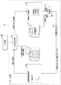
図16は、本発明の第2実施形態に係るデータベース装置10Aにより実行される再編成処理全体における各構成要件間の関係を簡単に示す説明図である。図16に示すように、本実施形態では、再編成部24は、コピーDB12ではなくオリジナルDB11を再編成する。
FIG. 16 is an explanatory diagram simply showing the relationship between the constituent elements in the entire reorganization process executed by the
次に、本実施形態に係るデータベース装置10Aの動作の一例について説明する。
Next, an example of the operation of the
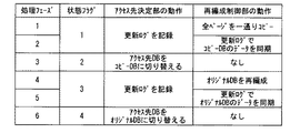
図17は、第2実施形態に係る再編成処理を進捗に応じて複数の処理フェーズに分類する一例を示す説明図である。また、図18は、第2実施形態に係る再編成処理における処理フェーズ、状態フラグ、アクセス先決定部21の動作および再編成制御部22の動作の関係を示す説明図である。
FIG. 17 is an explanatory diagram illustrating an example of classifying the reorganization process according to the second embodiment into a plurality of process phases according to progress. FIG. 18 is an explanatory diagram showing the relationship among the processing phase, the status flag, the operation of the access
図17および図18に示すように、本実施形態に係る再編成処理は7つのフェーズに分類される。第1実施形態におけるフェーズ2とフェーズ3の間に新たなフェーズおよび状態フラグが設けられた点が第1実施形態に係る再編成処理と異なる。フェーズ0、1および2は第1実施形態に係る再編成処理と同一であるため、説明を省略する。
As shown in FIGS. 17 and 18, the reorganization processing according to the present embodiment is classified into seven phases. The difference from the reorganization processing according to the first embodiment is that a new phase and state flag are provided between
コピーDB12に更新ログが適用された後、アクセス先決定部21によりアクセス先がコピーDB12へ切り替えられる期間はフェーズ3に分類される。コピーDB12にアクセス先が切り替えられた後、再編成部24によりオリジナルDB11が再編成されている期間はフェーズ4に分類される。オリジナルDB11が再編成された後、同期部25によりオリジナルDB11に対してフェーズ4開始以降に生成された更新ログが適用されている期間はフェーズ5に分類される。オリジナルDB11に更新ログが適用された後、アクセス先決定部21によりアクセス先がオリジナルDB11へ切り替えられる期間はフェーズ6に分類される。
After the update log is applied to the
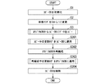
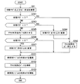
図19は、第2実施形態に係るデータベース装置10Aの主制御部13により、オリジナルDBを再編成する場合においてアプリケーションプログラムによるデータベースアクセスに対する妨害を低減しつつ確実にデータベースの再編成処理を行う際の手順を示すフローチャートである。図19において、Sに数字を付した符号は、フローチャートの各ステップを示す。図5と同等のステップには同一符号を付し、重複する説明を省略する。
FIG. 19 shows a case where the
この手順は、再編成処理の開始指示があった時点でスタートとなる。なお、再編成処理の開始指示は、データベースユーザによって図示しない入力部を介して与えられてもよいし、あらかじめ設定された所定の時間や所定の周期で自動的に与えられてもよい。 This procedure starts when there is an instruction to start the reorganization process. The reorganization process start instruction may be given by the database user via an input unit (not shown), or may be automatically given at a predetermined time or a predetermined cycle.
コピー部23によるコピーが終了すると、ステップS201において、同期部25は、ステップS3の間にオリジナルDB11に対して行われた更新をコピーDB12に適用してオリジナルDB11とコピーDB12との同期を行う。また、同期部25は、この同期処理の間に行われた更新についてもコピーDB12に適用し、オリジナルDB11とコピーDB12との同期を行う。
When copying by the
なお、ステップS201の処理は図5のステップS4とほぼ同一であり、詳細な手順も図8に示す手順とほぼ同一であり、図8のステップS48で移行する状態フラグ2(処理フェーズ3)が意味するところのみが異なり、アクセス先決定部21は、アクセス部100のアクセス先をオリジナルDB11からコピーDB12に変更する(図18参照)。なお、状態フラグは、アクセス先の切り替えが終わった時点でアクセス先決定部21により2から3に更新されても(処理フェーズが3から4に移行しても)よいし、アクセス部100による更新アクセスまたは参照アクセスがあるとアクセス先決定部21により2から3に更新されても(処理フェーズが3から4に移行しても)よい。
The process in step S201 is almost the same as step S4 in FIG. 5, the detailed procedure is almost the same as the procedure shown in FIG. 8, and the status flag 2 (processing phase 3) to be shifted in step S48 in FIG. The access
次に、ステップS202において、再編成部24は、オリジナルDB11を再編成する。この再編成の間、コピーDB12に対する更新アクセスは禁止されず、更新ログが更新ログ記憶部15に追記されていく。再編成されると、処理フェーズは4から5に移行する。
Next, in step S202, the
次に、ステップS203において、同期部25は、ステップS202の間にコピーDB12に対して行われた更新をオリジナルDB11に適用してオリジナルDB11とコピーDB12との同期を行う。また、同期部25は、この同期処理の間にコピーDB12に対して行われた更新についてもオリジナルDB11に適用し、オリジナルDB11とコピーDB12との同期を行う。同期されると、最終同期部32により状態フラグが3から4に更新される(処理フェーズが5から6に移行する)。そして、アクセス先決定部21は、アクセス部100のアクセス先をコピーDB12からオリジナルDB11に変更する。
Next, in step S203, the
次に、ステップS204において、再編成制御部22は、コピー部23を介してコピーDB12を削除する。
Next, in step S <b> 204, the
以上の手順により、オリジナルDB11を再編成する場合においても、アプリケーションプログラムによるデータベースアクセスに対する妨害を低減しつつ確実にデータベースの再編成処理を行うことができる。
According to the above procedure, even when the
続いて、オリジナルDB11の再編成後にオリジナルDB11に更新ログを適用してオリジナルDB11とコピーDB12との同期を行う際の手順を説明する。
Next, a procedure for synchronizing the
図20は、図19のステップS203で主制御部13により実行される再編成後の同期の手順を示すサブルーチンフローチャートである。図20において、Sに数字を付した符号は、フローチャートの各ステップを示す。なお、図11と同等のステップには同一符号を付し、重複する説明を省略する。
FIG. 20 is a subroutine flowchart showing a synchronization procedure after reorganization executed by the
この手順は、図19のステップS202で処理フェーズが4から5に移行した時点でスタートとなる。 This procedure starts when the processing phase shifts from 4 to 5 in step S202 of FIG.
更新ログ記憶部15に記憶された更新ログの数が閾値以下であると(ステップS41のYES)、初期同期部31は、更新ログ記憶部15から更新ログを1つ取得し(ステップS42)、取得した更新ログをオリジナルDB11に適用して(ステップS241)、ステップS41に戻る。
When the number of update logs stored in the update
一方、閾値以下である場合は(ステップS41のYES)、最終同期部32は、コピーDB12の排他ロックを取得する(ステップS242)。
On the other hand, if it is equal to or less than the threshold (YES in step S41), the
そして、更新ログ数がゼロでない場合は(ステップS45のNO)、最終同期部32は、更新ログ記憶部15から更新ログを1つ取得し(ステップS46)、取得した更新ログをオリジナルDB11に適用して(ステップS243)、ステップS45に戻る。
If the number of update logs is not zero (NO in step S45), the
一方、更新ログ数がゼロである場合は(ステップS45のYES)、最終同期部32は、進捗情報記憶部14に記憶された状態フラグを3から4に更新する(ステップS244)。すなわち、処理フェーズは5から6に移行する。そして、最終同期部32は、コピーDB12の排他ロックを開放する(ステップS245)。
On the other hand, when the number of update logs is zero (YES in step S45), the
以上の手順により、アプリケーションプログラムのデータベースアクセスの妨害を低減しつつ、オリジナルDB11の再編成後にオリジナルDB11に更新ログを適用してオリジナルDB11とコピーDB12との同期を行うことができる。
With the above procedure, it is possible to synchronize the
図21は、第2実施形態におけるアクセス部100から更新要求を受けたアクセス先決定部21の処理手順を示すフローチャートである。図21において、Sに数字を付した符号は、フローチャートの各ステップを示す。なお、図14と同等のステップには同一符号を付し、重複する説明を省略する。
FIG. 21 is a flowchart illustrating a processing procedure of the access
この手順は、アクセス先決定部21がアクセス部100からデータの更新要求を受けた時点でスタートとなる。なお、この手順はゼロを含む全ての状態フラグ値に対応するものである。
This procedure starts when the access
まず、アクセス先決定部21は、状態フラグおよびコピー状況を取得し(ステップS81)、状態フラグが3であるか否かを判定する(ステップS281)。状態フラグが3であればアクセス先決定部21はアクセス先をコピーDB12とする(ステップS282)。
First, the access
一方、状態フラグが3でない場合(ステップS281のNO)は、アクセス先決定部21は、状態フラグが2であるか否かを判定する(ステップS283)。状態フラグが2である場合は、アクセス先決定部21は、進捗情報記憶部14に記憶された状態フラグを2から3に更新して(ステップS284)アクセス先をコピーDB12とする(ステップS282)。
On the other hand, when the status flag is not 3 (NO in step S281), the access
状態フラグが2でも3でもない場合(ステップS283のNO)、アクセス先決定部21は、アクセス先をオリジナルDB11とし(ステップS285)、状態フラグが4であるか否かを判定し(ステップS286)、状態フラグが4である場合は、進捗情報記憶部14に記憶された状態フラグを4から0に更新する(ステップS287)。
If the status flag is neither 2 nor 3 (NO in step S283), the access
また、ステップS86でアクセス先のDBが更新され、ステップS87で状態フラグが1ではないと判定されると、アクセス先決定部21は、状態フラグが3であるか否かを判定する(ステップS288)。状態フラグが3である場合は、アクセス先決定部21は、更新ログ記憶部15に更新ログを記憶させて(ステップS89)、更新先テーブルの排他ロックを開放し(ステップS90)、一連の手順は終了となる。一方、状態フラグが3でない場合は、アクセス先決定部21は、更新ログを生成することなく更新先テーブルの排他ロックを開放し(ステップS90)、一連の手順は終了となる。
When the access destination DB is updated in step S86 and the status flag is determined not to be 1 in step S87, the access
図22は、第2実施形態におけるアクセス部100から参照要求を受けたアクセス先決定部21の処理手順を示すフローチャートである。図22において、Sに数字を付した符号は、フローチャートの各ステップを示す。図22に示す手順は、図15と図21に示したステップと同等のステップにより構成されるため、説明を省略する。
FIG. 22 is a flowchart illustrating a processing procedure of the access
本実施形態に係るデータベース装置10Aによっても、第1実施形態に係るデータベース装置10と同様の作用効果を奏する。また、本実施形態に係るデータベース装置10Aによれば、オリジナルDB11を再編成することができるため、一連の再編成処理の前後でオリジナルDB11をアクセス先とすることができる。
The
なお、本発明のいくつかの実施形態を説明したが、これらの実施形態は、例として提示したものであり、発明の範囲を限定することは意図していない。これら新規な実施形態は、その他の様々な形態で実施されることが可能であり、発明の要旨を逸脱しない範囲で、種々の省略、置き換え、変更を行うことができる。これら実施形態やその変形は、発明の範囲や要旨に含まれるとともに、特許請求の範囲に記載された発明とその均等の範囲に含まれる。 In addition, although some embodiment of this invention was described, these embodiment is shown as an example and is not intending limiting the range of invention. These novel embodiments can be implemented in various other forms, and various omissions, replacements, and changes can be made without departing from the scope of the invention. These embodiments and modifications thereof are included in the scope and gist of the invention, and are included in the invention described in the claims and the equivalents thereof.
たとえば、本実施形態では、再編成処理の対象をデータベース単位としたが、テーブル単位など他の単位としてもよい。 For example, in this embodiment, the target of the reorganization process is a database unit, but other units such as a table unit may be used.
また、本発明の実施形態では、フローチャートの各ステップは、記載された順序に沿って時系列的に行われる処理の例を示したが、必ずしも時系列的に処理されなくとも、並列的あるいは個別実行される処理をも含むものである。 Further, in the embodiment of the present invention, each step of the flowchart shows an example of processing that is performed in time series in the order described. The process to be executed is also included.
10 データベース装置
11 オリジナルDB
12 コピーDB
13 主制御部
14 進捗情報記憶部
15 更新ログ記憶部
21 アクセス先決定部
22 再編成制御部
23 コピー部
24 再編成部
25 同期部
31 初期同期部
32 最終同期部
10
12 Copy DB
13
Claims (3)
コピーデータベースを作成するコピー部と、
コピー、再編成および同期からなる一連の処理の進捗状況を示す状態フラグを記憶する
進捗情報記憶部と、
前記状態フラグがコピー中もしくはコピー後の同期中を示す値であると、前記元データベ
ースをアプリケーションプログラムのアクセス先とし、前記アプリケーションプログラム
により前記元データベースのデータのうちコピー中またはコピー済みのデータが更新され
るごとに、更新後の値の情報および更新されたデータを識別するための情報を含む更新ロ
グを更新ログ記憶部に記憶させ、前記状態フラグが再編成中もしくは再編成後の同期中を
示す値であると、前記コピーデータベースを前記アプリケーションプログラムのアクセス
先とし、前記アプリケーションプログラムにより前記コピーデータベースのデータが更新
されるごとに、前記更新ログを前記更新ログ記憶部に記憶させるアクセス先決定部と、
前記コピー部による前記コピーデータベースの作成が終わり、かつ前記更新ログ記憶部
に記憶された前記更新ログの数が閾値より多いと、前記元データベースの排他ロックを取
得せず、前記アプリケーションプログラムによる前記元データベースのデータの更新が許
可され更新に応じた前記アクセス先決定部による前記更新ログの生成が継続されたまま、
前記更新ログ記憶部に記憶された前記更新ログを1つずつ前記コピーデータベースに適用
するとともに適用した前記更新ログを前記更新ログ記憶部から削除する処理を前記更新ロ
グ記憶部に記憶された前記更新ログの数が閾値以下となるまで繰り返す初期同期部と、
前記コピー部による前記コピーデータベースの作成が終わり、かつ前記更新ログ記憶部
に記憶された前記更新ログの数が閾値以下であると、前記元データベースの排他ロックを
取得して前記元データベースのデータに対する更新および参照を禁止し、前記更新ログ記
憶部に記憶された前記更新ログを1つずつ前記コピーデータベースに適用するとともに適
用した前記更新ログを前記更新ログ記憶部から削除し、前記更新ログ記憶部に記憶された
前記更新ログの数がゼロになると、前記元データベースの前記排他ロックを開放すること
により、前記元データベースと前記コピー部により作成された前記コピーデータベースと
を同期するとともに、前記状態フラグを、前記アプリケーションプログラムのアクセス先
を前記コピーデータベースに切り替え中であると示す値に更新する最終同期部と、
前記元データベースと前記コピー部により作成された前記コピーデータベースとが前記
最終同期部により同期され、前記アクセス先決定部により前記状態フラグに基づいて前記
アプリケーションプログラムのアクセス先が前記コピーデータベースに切り替えられると
ともに前記状態フラグが再編成中もしくは再編成後の同期中を示す値に更新されると、前
記元データベースを再編成する再編成部と、
を備え、
前記初期同期部はさらに、
前記再編成部による前記元データベースの再編成が終わり、かつ前記更新ログ記憶部に
記憶された前記更新ログの数が閾値より多いと、前記コピーデータベースの排他ロックを
取得せずに前記更新ログ記憶部に記憶された前記更新ログを1つずつ前記元データベース
に適用するとともに適用後の前記更新ログを前記更新ログ記憶部から削除する処理を前記
更新ログ記憶部に記憶された前記更新ログの数が閾値以下となるまで繰り返し、
前記最終同期部はさらに、
前記再編成部による前記元データベースの再編成が終わり、かつ前記更新ログ記憶部に
記憶された前記更新ログの数が閾値以下であると、前記コピーデータベースの排他ロック
を取得して前記更新ログ記憶部に記憶された前記更新ログを1つずつ前記元データベース
に適用するとともに適用後の前記更新ログを前記更新ログ記憶部から削除し、前記更新ロ
グ記憶部に記憶された前記更新ログの数がゼロになると、前記コピーデータベースの前記
排他ロックを開放することにより、前記コピーデータベースと前記再編成部により再編成
された前記元データベースとを同期するとともに、前記状態フラグを、前記アプリケーシ
ョンプログラムのアクセス先を前記元データベースに切り替え中であると示す値に更新し
、
前記アクセス先決定部はさらに、
前記状態フラグが前記アプリケーションプログラムのアクセス先を前記元データベースに
切り替え中であると示す値であると、前記元データベースを前記アプリケーションプログ
ラムのアクセス先とし、前記状態フラグを通常状態を示す値とする、
データベース装置。 A copy unit that copies the data of the original database stored in the first volume and creates a copy database in the second volume;
A progress information storage unit that stores a status flag indicating a progress status of a series of processes including copying, reorganization, and synchronization;
If the status flag is a value indicating that copying is in progress or being synchronized after copying, the original database is used as an access destination of the application program, and the data being copied or copied among the data of the original database is updated by the application program Each time an update log including updated value information and information for identifying updated data is stored in the update log storage unit, the status flag indicates whether reorganization or synchronization after reorganization is in progress. An access destination determination unit that stores the update log in the update log storage unit each time data in the copy database is updated by the application program. When,
When the creation of the copy database by the copy unit is finished and the number of the update logs stored in the update log storage unit is larger than a threshold, an exclusive lock of the original database is not acquired, and the original by the application program is acquired. While updating of the data in the database is permitted and the generation of the update log by the access destination determination unit according to the update is continued,
The update stored in the update log storage unit is applied to the copy database one by one with the update log stored in the update log storage unit and the applied update log is deleted from the update log storage unit. An initial synchronization unit that repeats until the number of logs falls below a threshold;
When the creation of the copy database by the copy unit is finished and the number of the update logs stored in the update log storage unit is less than or equal to a threshold, an exclusive lock of the original database is acquired and the data of the original database is Update and reference are prohibited, the update logs stored in the update log storage unit are applied to the copy database one by one, and the applied update log is deleted from the update log storage unit, and the update log storage unit When the number of the update logs stored in the database becomes zero, the exclusive lock of the original database is released to synchronize the original database with the copy database created by the copy unit, and the status flag Switch the access destination of the application program to the copy database. And final synchronization unit for updating the value indicated as being in place,
Wherein said copy database created by the copy unit to the original database is synchronized by the last synchronization unit, the access destination of the application program based on the state flag by said access destination determining section is switched to the copy database And when the status flag is updated to a value indicating reorganization or synchronization after reorganization, a reorganization unit reorganizing the original database;
With
The initial synchronization unit further includes:
When reorganization of the original database by the reorganization unit is completed and the number of update logs stored in the update log storage unit is greater than a threshold, the update log storage is not performed without acquiring an exclusive lock of the copy database. The number of the update logs stored in the update log storage unit for applying the update logs stored in the storage unit to the original database one by one and deleting the applied update log from the update log storage unit Repeat until is below the threshold,
The final synchronization unit further includes
When the reorganization of the original database by the reorganization unit is finished and the number of the update logs stored in the update log storage unit is less than or equal to a threshold, an exclusive lock of the copy database is acquired and the update log storage The update logs stored in the storage unit are applied to the original database one by one and the applied update logs are deleted from the update log storage unit, and the number of the update logs stored in the update log storage unit is When zero, the copy database and the original database reorganized by the reorganization unit are synchronized by releasing the exclusive lock of the copy database, and the status flag is set to the access destination of the application program. To a value indicating that switching to the original database is in progress,
The access destination determination unit further includes
When the status flag is a value indicating that the access destination of the application program is being switched to the original database, the original database is the access destination of the application program, and the status flag is a value indicating a normal state.
Database device.
請求項1に記載のデータベース装置。 The threshold is zero;
The database device according to claim 1.
コピーデータベースを作成するステップと、
コピー、再編成および同期からなる一連の処理の進捗状況を示す状態フラグを進捗情報
記憶部に記憶させるステップと、
前記状態フラグがコピー中もしくはコピー後の同期中を示す値であると、前記元データベ
ースをアプリケーションプログラムのアクセス先とし、アプリケーションプログラムによ
り前記元データベースのデータのうちコピー中またはコピー済みのデータが更新されるご
とに、更新後の値の情報および更新されたデータを識別するための情報を含む更新ログを
更新ログ記憶部に記憶させるステップと、
前記状態フラグが再編成中もしくは再編成後の同期中を示す値であると、前記コピーデー
タベースをアプリケーションプログラムのアクセス先とし、前記アプリケーションプログ
ラムにより前記コピーデータベースのデータが更新されるごとに、前記更新ログを前記更
新ログ記憶部に記憶させるステップと、
前記コピーデータベースの作成が終わり、かつ前記更新ログ記憶部に記憶された前記更
新ログの数が閾値より多いと、前記元データベースの排他ロックを取得せず、前記アプリ
ケーションプログラムによる前記元データベースのデータの更新が許可され更新に応じた
前記更新ログの生成が継続されたまま、前記更新ログ記憶部に記憶された前記更新ログを
1つずつ前記コピーデータベースに適用するとともに適用した前記更新ログを前記更新ロ
グ記憶部から削除する処理を前記更新ログ記憶部に記憶された前記更新ログの数が閾値以
下となるまで繰り返すステップと、
前記コピーデータベースの作成が終わり、かつ前記更新ログ記憶部に記憶された前記更新
ログの数が閾値以下であると、前記元データベースの排他ロックを取得して前記元データ
ベースのデータに対する更新および参照を禁止し、前記更新ログ記憶部に記憶された前記
更新ログを1つずつ前記コピーデータベースに適用するとともに適用した前記更新ログを
前記更新ログ記憶部から削除する処理を前記更新ログ記憶部に記憶された前記更新ログの
数がゼロになるまで繰り返すステップと、
前記更新ログ記憶部に記憶された前記更新ログの数がゼロになると、前記元データベース
の前記排他ロックを開放するとともに、前記状態フラグを、前記アプリケーションプログ
ラムのアクセス先を前記コピーデータベースに切り替え中であると示す値に更新するステ
ップと、
前記更新された状態フラグに基づいて前記アプリケーションプログラムのアクセス先が前
記コピーデータベースに切り替えられるステップと、
前記状態フラグが再編成中もしくは再編成後の同期中を示す値に更新されるステップと、
前記元データベースを再編成するステップと、
前記元データベースの再編成が終わり、かつ前記更新ログ記憶部に記憶された前記更新
ログの数が閾値より多いと、前記コピーデータベースの排他ロックを取得せずに前記更新
ログ記憶部に記憶された前記更新ログを1つずつ前記元データベースに適用するとともに
適用した前記更新ログを前記更新ログ記憶部から削除する処理を前記更新ログ記憶部に記
憶された前記更新ログの数が閾値以下となるまで繰り返すステップと、
前記元データベースの再編成が終わり、かつ前記更新ログ記憶部に記憶された前記更新ロ
グの数が閾値以下であると、前記コピーデータベースの排他ロックを取得して前記更新ロ
グ記憶部に記憶された前記更新ログを1つずつ前記元データベースに適用するとともに適
用後の前記更新ログを前記更新ログ記憶部から削除する処理を前記更新ログ記憶部に記憶
された前記更新ログの数がゼロになるまで繰り返すステップと、
前記更新ログ記憶部に記憶された前記更新ログの数がゼロになると、前記コピーデータベ
ースの前記排他ロックを開放するとともに、前記状態フラグを、前記アプリケーションプ
ログラムのアクセス先を前記元データベースに切り替え中であると示す値に更新するステ
ップと、
前記再編成された元データベースをアプリケーションプログラムのアクセス先とするス
テップと、
前記状態フラグを通常状態を示す値とするステップと、
を有するデータベース再編成方法。 Copying the original database data stored in the first volume to create a copy database in the second volume;
Storing a status flag indicating a progress status of a series of processes including copying, reorganization, and synchronization in a progress information storage unit;
When the status flag is a value indicating that copying is in progress or synchronization after copying, the original database is used as the access destination of the application program, and the data copied or copied among the data of the original database is updated by the application program. in Rugoto, the update log includes information for identifying the information and updated data of the updated values
Further comprising the steps of storing the new log storage unit,
When the status flag is a value indicating that reorganization or synchronization is occurring after reorganization, the copy database is set as an access destination of the application program, and the update is performed each time the copy database data is updated by the application program. Storing a log in the update log storage unit;
When the creation of the copy database is completed and the number of update logs stored in the update log storage unit is greater than a threshold value, the exclusive lock of the original database is not acquired, and the data of the original database by the application program is not acquired. update is permitted according to the update
Processing for deleting remain generated before Symbol update log is continued, the update log of applying well as applied to the update log storage unit to said stored one by one update log the copy database from the update log storage unit Repeating until the number of the update logs stored in the update log storage unit is equal to or less than a threshold value;
When creation of the copy database is completed and the number of the update logs stored in the update log storage unit is equal to or less than a threshold value, an exclusive lock of the original database is acquired to update and reference the data of the original database. The update log storage unit stores a process for prohibiting and applying the update log stored in the update log storage unit to the copy database one by one and deleting the applied update log from the update log storage unit. Repeating until the number of update logs reaches zero,
When the number of the update logs stored in the update log storage unit becomes zero, the exclusive lock of the original database is released, and the status flag is being switched to the copy database as the access destination of the application program Updating to a value indicating that there is,
A step of switching the access destination of the application program to the copy database based on the updated status flag;
The status flag is updated to a value indicating reorganization or synchronization after reorganization;
Reorganizing the original database;
When the reorganization of the original database is completed and the number of the update logs stored in the update log storage unit is larger than a threshold, the copy database is stored in the update log storage unit without acquiring an exclusive lock. The process of applying the update log to the original database one by one and deleting the applied update log from the update log storage unit until the number of the update logs stored in the update log storage unit falls below a threshold value Repeating steps,
When the reorganization of the original database is completed and the number of the update logs stored in the update log storage unit is equal to or less than a threshold, an exclusive lock of the copy database is acquired and stored in the update log storage unit A process of applying the update logs to the original database one by one and deleting the applied update logs from the update log storage unit until the number of update logs stored in the update log storage unit becomes zero Repeating steps,
When the number of update logs stored in the update log storage unit becomes zero, the exclusive lock of the copy database is released, and the status flag is being switched to the original database as the access destination of the application program Updating to a value indicating that there is,
Making the reorganized original database an access destination of an application program;
Setting the state flag to a value indicating a normal state;
A database reorganization method.
Priority Applications (1)
| Application Number | Priority Date | Filing Date | Title |
|---|---|---|---|
| JP2011091583A JP5815975B2 (en) | 2011-04-15 | 2011-04-15 | Database apparatus and database reorganization method |
Applications Claiming Priority (1)
| Application Number | Priority Date | Filing Date | Title |
|---|---|---|---|
| JP2011091583A JP5815975B2 (en) | 2011-04-15 | 2011-04-15 | Database apparatus and database reorganization method |
Publications (3)
| Publication Number | Publication Date |
|---|---|
| JP2012226453A JP2012226453A (en) | 2012-11-15 |
| JP2012226453A5 JP2012226453A5 (en) | 2014-05-15 |
| JP5815975B2 true JP5815975B2 (en) | 2015-11-17 |
Family
ID=47276571
Family Applications (1)
| Application Number | Title | Priority Date | Filing Date |
|---|---|---|---|
| JP2011091583A Active JP5815975B2 (en) | 2011-04-15 | 2011-04-15 | Database apparatus and database reorganization method |
Country Status (1)
| Country | Link |
|---|---|
| JP (1) | JP5815975B2 (en) |
Families Citing this family (4)
| Publication number | Priority date | Publication date | Assignee | Title |
|---|---|---|---|---|
| KR102024719B1 (en) * | 2016-11-15 | 2019-09-25 | 한양대학교 산학협력단 | Method and apparatus for journaling of file-based database |
| KR101996895B1 (en) * | 2016-11-15 | 2019-07-08 | 한양대학교 산학협력단 | Method and apparatus for database recovery |
| KR102111555B1 (en) * | 2016-11-15 | 2020-05-18 | 한양대학교 산학협력단 | Method and apparatus for journaling of file-based database which is used by one application |
| JP7120985B2 (en) * | 2019-12-16 | 2022-08-17 | ヤフー株式会社 | Database management system, database management method, and program |
Family Cites Families (11)
| Publication number | Priority date | Publication date | Assignee | Title |
|---|---|---|---|---|
| JPH0667944A (en) * | 1992-08-24 | 1994-03-11 | Hitachi Ltd | Database management system |
| JPH0675840A (en) * | 1992-08-26 | 1994-03-18 | Hitachi Ltd | Database maintenance system |
| JPH06250901A (en) * | 1993-02-25 | 1994-09-09 | Nippon Telegr & Teleph Corp <Ntt> | Data base maintenance method |
| JPH0877050A (en) * | 1994-09-02 | 1996-03-22 | Nippon Telegr & Teleph Corp <Ntt> | Device and method for reconstituting data base |
| JP2003099306A (en) * | 2001-09-25 | 2003-04-04 | Hitachi Ltd | Computer system, and backup method in the computer system |
| JP2004139217A (en) * | 2002-10-16 | 2004-05-13 | Hewlett Packard Co <Hp> | Migration method for database |
| JP2004199264A (en) * | 2002-12-17 | 2004-07-15 | Hitachi Ltd | Data base processing method and device for its implementation and its processing program |
| JP2004318288A (en) * | 2003-04-11 | 2004-11-11 | Hitachi Ltd | Method and device for processing data and its processing program |
| JP4266786B2 (en) * | 2003-11-19 | 2009-05-20 | 株式会社日立製作所 | Information processing system and information processing apparatus |
| JP4683546B2 (en) * | 2005-07-15 | 2011-05-18 | 国立大学法人 東京大学 | Database reorganization method and database reorganization system |
| JP5000359B2 (en) * | 2007-04-04 | 2012-08-15 | 株式会社リコー | Information management system and information management method |
-
2011
- 2011-04-15 JP JP2011091583A patent/JP5815975B2/en active Active
Also Published As
| Publication number | Publication date |
|---|---|
| JP2012226453A (en) | 2012-11-15 |
Similar Documents
| Publication | Publication Date | Title |
|---|---|---|
| JP6309103B2 (en) | Snapshot and clone replication | |
| EP3518459B1 (en) | Object signatures in object stores | |
| KR101573965B1 (en) | Atomic multiple modification of data in a distributed storage system | |
| CN105528368B (en) | A kind of database migration method and device | |
| JPH04233639A (en) | File controlling method and system | |
| JP5815975B2 (en) | Database apparatus and database reorganization method | |
| US20200004852A1 (en) | Large content file optimization | |
| CN107391669A (en) | A kind of multi version file management method and device based on file system | |
| CN105469001B (en) | Disk data protection method and device | |
| JP4755244B2 (en) | Information generation method, information generation program, and information generation apparatus | |
| EP2669806B1 (en) | Storage system | |
| CN109753381B (en) | Continuous data protection method based on object storage | |
| US20090112951A1 (en) | Apparatus and method of managing files and memory device | |
| JP2008090378A (en) | Hybrid file system, operating system, cache control method, and recording medium | |
| KR20100089387A (en) | Method and apparatus for data security, and recording medium storing program to implement the method | |
| US10157106B1 (en) | Method controlling backup data by using snapshot type image table | |
| JP5740196B2 (en) | Database apparatus and database reorganization method | |
| JP2016189104A (en) | File management device, storage device, file management method, and program | |
| JP2005316708A (en) | Hierarchical storage device, its restoring method and restoration program | |
| TWI740429B (en) | Method and system for managing backup data | |
| JP4826610B2 (en) | Image processing apparatus and image erasing program | |
| JP3957464B2 (en) | Data update device | |
| JP2007272675A (en) | Snapshot creation device, method and program | |
| CN112711439A (en) | Automatic updating method for converting ASIC codes into FPGA codes | |
| JP2008123104A (en) | Data-access device |
Legal Events
| Date | Code | Title | Description |
|---|---|---|---|
| A521 | Written amendment |
Free format text: JAPANESE INTERMEDIATE CODE: A523 Effective date: 20140402 |
|
| A621 | Written request for application examination |
Free format text: JAPANESE INTERMEDIATE CODE: A621 Effective date: 20140402 |
|
| A977 | Report on retrieval |
Free format text: JAPANESE INTERMEDIATE CODE: A971007 Effective date: 20141113 |
|
| A131 | Notification of reasons for refusal |
Free format text: JAPANESE INTERMEDIATE CODE: A131 Effective date: 20141118 |
|
| A521 | Written amendment |
Free format text: JAPANESE INTERMEDIATE CODE: A523 Effective date: 20150119 |
|
| A02 | Decision of refusal |
Free format text: JAPANESE INTERMEDIATE CODE: A02 Effective date: 20150331 |
|
| A521 | Written amendment |
Free format text: JAPANESE INTERMEDIATE CODE: A523 Effective date: 20150630 |
|
| A911 | Transfer to examiner for re-examination before appeal (zenchi) |
Free format text: JAPANESE INTERMEDIATE CODE: A911 Effective date: 20150707 |
|
| A131 | Notification of reasons for refusal |
Free format text: JAPANESE INTERMEDIATE CODE: A131 Effective date: 20150731 |
|
| A521 | Written amendment |
Free format text: JAPANESE INTERMEDIATE CODE: A523 Effective date: 20150810 |
|
| TRDD | Decision of grant or rejection written | ||
| A01 | Written decision to grant a patent or to grant a registration (utility model) |
Free format text: JAPANESE INTERMEDIATE CODE: A01 Effective date: 20150828 |
|
| A61 | First payment of annual fees (during grant procedure) |
Free format text: JAPANESE INTERMEDIATE CODE: A61 Effective date: 20150925 |
|
| R151 | Written notification of patent or utility model registration |
Ref document number: 5815975 Country of ref document: JP Free format text: JAPANESE INTERMEDIATE CODE: R151 |