JP5813644B2 - Guide wire - Google Patents
Guide wire Download PDFInfo
- Publication number
- JP5813644B2 JP5813644B2 JP2012531201A JP2012531201A JP5813644B2 JP 5813644 B2 JP5813644 B2 JP 5813644B2 JP 2012531201 A JP2012531201 A JP 2012531201A JP 2012531201 A JP2012531201 A JP 2012531201A JP 5813644 B2 JP5813644 B2 JP 5813644B2
- Authority
- JP
- Japan
- Prior art keywords
- wire
- wire coil
- coil
- hollow shaft
- fluid
- Prior art date
- Legal status (The legal status is an assumption and is not a legal conclusion. Google has not performed a legal analysis and makes no representation as to the accuracy of the status listed.)
- Active
Links
Images


Classifications
-
- A—HUMAN NECESSITIES
- A61—MEDICAL OR VETERINARY SCIENCE; HYGIENE
- A61M—DEVICES FOR INTRODUCING MEDIA INTO, OR ONTO, THE BODY; DEVICES FOR TRANSDUCING BODY MEDIA OR FOR TAKING MEDIA FROM THE BODY; DEVICES FOR PRODUCING OR ENDING SLEEP OR STUPOR
- A61M25/00—Catheters; Hollow probes
- A61M25/01—Introducing, guiding, advancing, emplacing or holding catheters
- A61M25/09—Guide wires
- A61M2025/09058—Basic structures of guide wires
- A61M2025/09083—Basic structures of guide wires having a coil around a core
-
- A—HUMAN NECESSITIES
- A61—MEDICAL OR VETERINARY SCIENCE; HYGIENE
- A61M—DEVICES FOR INTRODUCING MEDIA INTO, OR ONTO, THE BODY; DEVICES FOR TRANSDUCING BODY MEDIA OR FOR TAKING MEDIA FROM THE BODY; DEVICES FOR PRODUCING OR ENDING SLEEP OR STUPOR
- A61M25/00—Catheters; Hollow probes
- A61M25/01—Introducing, guiding, advancing, emplacing or holding catheters
- A61M25/09—Guide wires
- A61M2025/091—Guide wires having a lumen for drug delivery or suction
-
- A—HUMAN NECESSITIES
- A61—MEDICAL OR VETERINARY SCIENCE; HYGIENE
- A61M—DEVICES FOR INTRODUCING MEDIA INTO, OR ONTO, THE BODY; DEVICES FOR TRANSDUCING BODY MEDIA OR FOR TAKING MEDIA FROM THE BODY; DEVICES FOR PRODUCING OR ENDING SLEEP OR STUPOR
- A61M25/00—Catheters; Hollow probes
- A61M25/01—Introducing, guiding, advancing, emplacing or holding catheters
- A61M25/09—Guide wires
- A61M2025/09175—Guide wires having specific characteristics at the distal tip
-
- A—HUMAN NECESSITIES
- A61—MEDICAL OR VETERINARY SCIENCE; HYGIENE
- A61M—DEVICES FOR INTRODUCING MEDIA INTO, OR ONTO, THE BODY; DEVICES FOR TRANSDUCING BODY MEDIA OR FOR TAKING MEDIA FROM THE BODY; DEVICES FOR PRODUCING OR ENDING SLEEP OR STUPOR
- A61M25/00—Catheters; Hollow probes
- A61M25/01—Introducing, guiding, advancing, emplacing or holding catheters
- A61M25/09—Guide wires
- A61M25/09016—Guide wires with mandrils
- A61M25/09033—Guide wires with mandrils with fixed mandrils, e.g. mandrils fixed to tip; Tensionable wires
Description
本発明は、ヒトおよび/または動物の中空器官、特に血管において流体を導入および/または除去するように構成された、カテーテル用のガイドワイヤに関する。前記ガイドワイヤは、流体を送出および/または回収するための管腔を有する長尺の中空シャフトと、前記中空シャフトの遠位端部に同軸上に装着された可撓性ワイヤコイルの形態の挿入補助具と、を備え、ガイドワイヤ先端部が遠位端部に配置され、ガイドワイヤの可撓性を制御するために芯ワイヤが中空シャフトの管腔内に配置され、前記芯ワイヤは、管腔の外に長手方向におよびワイヤコイルを貫通してガイドワイヤ先端部まで延在する。さらに、本発明は、血管および/または腫瘍の診断処置および/または治療処置のための方法と、ヒトおよび/または動物の身体に対する診断および/または治療を目的とするガイドワイヤの使用と、に関する。 The present invention relates to a guide wire for a catheter configured to introduce and / or remove fluid in human and / or animal hollow organs, particularly blood vessels. The guidewire is inserted in the form of a long hollow shaft having a lumen for delivering and / or collecting fluid, and a flexible wire coil coaxially mounted at the distal end of the hollow shaft. And a guide wire tip is disposed at the distal end, and a core wire is disposed within the lumen of the hollow shaft to control the flexibility of the guide wire, the core wire comprising a tube It extends longitudinally out of the cavity and through the wire coil to the guidewire tip. Furthermore, the invention relates to a method for the diagnostic and / or therapeutic treatment of blood vessels and / or tumors and the use of a guide wire for diagnostic and / or therapeutic purposes on the human and / or animal body.
ガイドワイヤは通常、ヒトおよび/または動物の中空器官内にカテーテルを挿入する補助具としての役割を果たす。ガイドワイヤは、カテーテルを挿入する前に中空器官内に押し入れられかつ所望の箇所に位置決めされる。これを行うために、ガイドワイヤは、例えば狭くかつ著しく湾曲した血管の経路に沿って進めるように、遠位端部にて十分な可撓性を有しかつ薄いものでなければならない。しかしながら、それと同時に、ガイドワイヤは、近位端部の方向から前方に確実に押し入れることができるように十分な剛性をも有さなければならない。 Guidewires usually serve as an aid to insert a catheter into the hollow organ of humans and / or animals. The guidewire is pushed into the hollow organ and positioned at the desired location prior to inserting the catheter. In order to do this, the guidewire must be sufficiently flexible and thin at the distal end, for example, to advance along a narrow and highly curved vessel path. At the same time, however, the guidewire must also be sufficiently rigid so that it can be pushed forward in the direction of the proximal end.
例えば液体を導入および/または除去するために使用されるとともに、中空器官内において圧力測定プローブとして機能する中空ガイドワイヤもまた知られている。この種のガイドワイヤは、例えば、その近位部分において、ガイドワイヤ先端部を有する比較的可撓性の螺旋ばねを遠位端部に有する中空鋼チューブを有する。ガイドワイヤの剛性を制御するために、芯ワイヤが、例えば前記鋼チューブの遠位端部上に取り付けられる。前記芯ワイヤは、螺旋ばねを貫通してガイドワイヤ先端部まで延在する。さらに、螺旋ばねの近位端部の区域において、芯ワイヤは、ガイドワイヤの所定のスライドを可能にするために、前記螺旋ばねの近位端部の区域にその全周にわたり完全に溶接される。 Hollow guidewires are also known that are used, for example, to introduce and / or remove liquids and function as pressure measuring probes within hollow organs. This type of guidewire has, for example, a hollow steel tube with a relatively flexible helical spring at its distal end with a guidewire tip at its proximal portion. In order to control the stiffness of the guide wire, a core wire is mounted on the distal end of the steel tube, for example. The core wire extends through the spiral spring to the tip of the guide wire. Furthermore, in the area of the proximal end of the helical spring, the core wire is completely welded to the area of the proximal end of the helical spring in its entire circumference in order to allow a predetermined slide of the guide wire. .
前記ガイドワイヤを介して流体を送出および/または回収するために、1つまたは複数の側方開口が、ワイヤコイルの後の鋼チューブ中に形成される。このようにすることで、流体が、中空ガイドワイヤおよび側方開口を介して中空器官内に送出され得る、または、流体が、側方開口およびガイドワイヤを介して中空器官から除去される。圧力測定プローブとして使用される中空ガイドワイヤは、例えば特許文献1(サイメッド・ライフ・システムズ・インコーポレーテッド社)などに記載されている。 One or more side openings are formed in the steel tube after the wire coil to deliver and / or collect fluid through the guidewire. In this way, fluid can be delivered into the hollow organ via the hollow guidewire and side opening, or fluid can be removed from the hollow organ via the side opening and guidewire. A hollow guide wire used as a pressure measuring probe is described in, for example, Patent Document 1 (Cymed Life Systems Inc.).
注入用の偏向自在なガイドワイヤが、特許文献2(ジョンソン・エンド・ジョンソン社)より知られている。前記可動端部は、ワイヤコイルにより形成される。注入液体をワイヤコイルの区域内に送るために、ガイドワイヤは、独立した注入チューブを収容する。前記注入チューブは、近位端部からワイヤコイルの区域内に延在し、前記区域において、治療液体が、ワイヤコイルの巻線同士の間の隙間を介してガイドワイヤから流出することが可能となる。ワイヤコイルは、プラスチックから作製された内方ジャケットと外方ジャケットとの間に収容される。この場合の欠点は、別個の注入チューブが、ガイドワイヤ内に収容されなければならない点、およびコイル区域における液体の放出を制御することができない点である。 A deflectable guide wire for injection is known from Patent Document 2 (Johnson & Johnson). The movable end is formed by a wire coil. In order to deliver the infusion liquid into the area of the wire coil, the guide wire contains a separate infusion tube. The infusion tube extends from the proximal end into the area of the wire coil, where treatment liquid can flow out of the guide wire through the gap between the windings of the wire coil. Become. The wire coil is housed between an inner jacket and an outer jacket made from plastic. The disadvantage in this case is that a separate infusion tube must be accommodated in the guide wire and the discharge of liquid in the coil area cannot be controlled.
特許文献3(インターベンショナル・イノベーションズ社)は、遠位部分が近位部分よりも小さな直径を有するガイドワイヤを開示している。タングステンまたは白金から作製される開口ワイヤコイルが、ガイドワイヤの遠位部分上に固定されることにより、ガイドワイヤの遠位先端部が組織を保護するために比較的軟質になる。中空ワイヤの遠位端部からワイヤコイル内に突出するロッド要素が、液体交換用の溝を備える。前記開口ワイヤコイルは、溝がガイドワイヤから現れるその正確な位置だけで、液体の放出が可能となるようなものであり、液体の輸送には適さない。 U.S. Patent No. 6,057,031 (Intervention Innovations) discloses a guidewire having a distal portion with a smaller diameter than the proximal portion. An open wire coil made from tungsten or platinum is secured on the distal portion of the guidewire, thereby making the distal tip of the guidewire relatively soft to protect the tissue. A rod element protruding into the wire coil from the distal end of the hollow wire comprises a groove for liquid exchange. The open wire coil is such that the liquid can be discharged only at the exact position where the groove emerges from the guide wire and is not suitable for liquid transport.
特許文献4(コーディス・コーポレイション社)は、液体の輸送システムを有する別のガイドワイヤを開示している。ワイヤコイルが、芯ワイヤ上に巻き付けられ、プラスチックジャケットが、ワイヤコイルの外側に取り付けられる。液体は、コイルの合間の螺旋状ライン構成部分内を進められる。液体は、前記プラスチックエンクロージャの端部にて出ることが可能である。欠点は、螺旋状ライン構成部分内で液体を案内することによって、チャネルが非常に長くかつ狭いものとなり、それに応じて流動抵抗が高くなる点である。 U.S. Patent No. 6,057,028 (Cordis Corporation) discloses another guidewire having a liquid transport system. A wire coil is wrapped around the core wire and a plastic jacket is attached to the outside of the wire coil. The liquid is advanced in a helical line component between the coils. Liquid can exit at the end of the plastic enclosure. The disadvantage is that by guiding the liquid in the helical line component, the channel becomes very long and narrow and the flow resistance increases accordingly.
特許文献5(レイクリージョンマニュファクチュアリング社)は、外方螺旋ばねおよび内方螺旋ばねから構成され、これらのばねの中央に芯ワイヤが配置された、ガイドワイヤを提案している。外方螺旋ばねは、螺旋ラインとして形状設定され、相互に平行に延在し相互に連結される4つのコイルワイヤから構成される、リボン構造を有する。内方螺旋ばねは、単一のワイヤにより形成され、隣接し合う巻線同士の間には間隔が存在する。これらのコイルは、ガイドワイヤがトルクを伝達することが可能となるように、対向し合う方向に巻かれている。螺旋ばねの主要部分は、ガイドワイヤの最大制御を実現するように緊密に巻かれる。螺旋ワイヤは、遠位端部では間隔を有して巻かれ、巻線同士間の間隔は、注入開口としての役割を果たす。膜が、内方コイルの内面上に、または内方コイルと外方コイルとの間に設けられて、芯ワイヤがさらに中に配置される中央管腔を、流入液体のためのチャネルとして用いることが可能となる。 Patent Document 5 (Lake Region Manufacturing Co., Ltd.) proposes a guide wire which is composed of an outer spiral spring and an inner spiral spring, and a core wire is arranged at the center of these springs. The outer spiral spring is shaped as a spiral line and has a ribbon structure composed of four coil wires extending parallel to each other and connected to each other. The inner spiral spring is formed by a single wire, and there is a gap between adjacent windings. These coils are wound in opposite directions so that the guide wire can transmit torque. The main part of the spiral spring is tightly wound to achieve maximum control of the guide wire. The spiral wire is wound at a distance at the distal end, and the spacing between the windings serves as an injection opening. Using a central lumen in which the membrane is provided on the inner surface of the inner coil or between the inner and outer coils and in which the core wire is further disposed as a channel for the incoming liquid Is possible.
しかしながら、現在知られている、流体を送出および/または回収する中空ガイドワイヤは、完全に満足のゆくものではない。 However, currently known hollow guidewires for delivering and / or recovering fluid are not completely satisfactory.
したがって、流体を送出および/または回収するための、改良されたおよび容易に挿入可能なガイドワイヤが依然として必要とされている。 Accordingly, there remains a need for an improved and easily insertable guidewire for delivering and / or retrieving fluid.
本発明の目的は、冒頭で述べた技術分野に属し、ヒトおよび/または動物の中空器官における流体のより正確な送出および/または除去を可能にする、容易に挿入可能なガイドワイヤを提供することである。 The object of the present invention is to provide an easily insertable guidewire that belongs to the technical field mentioned at the outset and allows for more accurate delivery and / or removal of fluids in the hollow organs of humans and / or animals. It is.
前記目的は、請求項1において規定される特徴により達成される。本発明によれば、近位方向においてガイドワイヤ先端部に隣接するワイヤコイルの遠位内方区域が、芯ワイヤに沿って形成される流体チャネルを介して中空シャフトの管腔と連通し、さらに、導入および/または除去すべき流体のための少なくとも1つの外方向に開いた貫通開口を有する。
The object is achieved by the features defined in
ここでは、ワイヤコイルは、特に、長手方向軸を中心として螺旋状に巻かれたワイヤにより形成された中空円筒状構造体として理解すべきである。ワイヤコイルは、特に、例えば白金などの金属ワイヤから形成される。しかしながら、ワイヤコイルのワイヤは、必ずしも金属から作製されなければならないわけではない。さらに、原則として、プラスチックから作製されるワイヤを用意することも考えられる。 Here, a wire coil is to be understood in particular as a hollow cylindrical structure formed by a wire wound helically around a longitudinal axis. The wire coil is formed in particular from a metal wire such as platinum, for example. However, the wire of the wire coil does not necessarily have to be made from metal. Furthermore, in principle, it is also conceivable to prepare a wire made of plastic.
芯ワイヤは、特に、例えば鋼などの金属から作製される。しかしながら、原則として、例えば高強度プラスチックおよび/または複合材料などの他の材料を、芯ワイヤに対して使用することも可能である。 The core wire is made in particular from a metal such as, for example, steel. However, in principle, other materials can also be used for the core wire, for example high strength plastics and / or composite materials.
本発明による貫通開口が、ガイドワイヤ先端部に隣接するワイヤコイルの遠位内方区域中に配置されるため、前記貫通開口は、ガイドワイヤ先端部の直近の区域に位置する。したがって、遠位内方区域と中空シャフトの管腔との間の流体チャネルと組み合わせることにより、流体を、ガイドワイヤからガイドワイヤ先端部の区域内に直に位置する中空器官内に導入することが可能となり、および/またはその中空器官から除去することが可能となる。ワイヤコイルの遠位内方区域の前記少なくとも1つの開口は、好ましくは、近位方向においてガイドワイヤ先端部に直に隣接する。 Since the through opening according to the invention is arranged in the distal inner section of the wire coil adjacent to the guide wire tip, the through opening is located in the area proximate to the guide wire tip. Thus, in combination with a fluid channel between the distal inner section and the lumen of the hollow shaft, fluid can be introduced from the guidewire into the hollow organ located directly in the section of the guidewire tip. And / or can be removed from the hollow organ. Said at least one opening in the distal inner section of the wire coil is preferably immediately adjacent to the guidewire tip in the proximal direction.
中空器官内におけるガイドワイヤ先端部の位置は、例えばX線などを使用する公知の撮像法などにより概して比較的正確に決定することが可能であるため、少なくとも1つの貫通開口がガイドワイヤ先端部に対して近傍に位置することにより、さらに、前記少なくとも1つの貫通開口の位置を非常に正確に決定することも可能となる。したがって、特に、貫通開口が近位方向においてワイヤコイルの後に配置される公知のガイドワイヤと比較した場合に、本発明によるガイドワイヤ中の貫通開口の位置は、より正確に決定され得る。 The position of the guidewire tip within the hollow organ can be determined relatively accurately, for example by known imaging methods using, for example, X-rays, so that at least one through-opening is at the guidewire tip. By being located in the vicinity, it is also possible to determine the position of the at least one through opening very accurately. Thus, the position of the through opening in the guide wire according to the invention can be determined more precisely, especially when compared to known guide wires in which the through opening is arranged after the wire coil in the proximal direction.
管腔からワイヤコイルを貫通してガイドワイヤ先端部まで延在する芯ワイヤにより、ガイドワイヤの遠位区域における弾性もまた、非常に正確に調節することが可能となり、これは、さらに、中空器官内におけるガイドワイヤの挿入性および制御性を向上させる。具体的には、例えば、中空シャフトとワイヤコイルとの間の移行区域における弾性の急激な変化を、例えば挿入時のガイドワイヤの捩れを抑制する芯ワイヤによって補償することが可能となる。同様に、通常は超弾性のワイヤコイルの弾性を、芯ワイヤにより低下させかつ特定の要件に適合させることが可能である。したがって、特に、とりわけ空間を節約する特に小さなワイヤ径を有するワイヤコイルを使用することが可能となる。したがって、ガイドワイヤまたはガイドワイヤ先端部は、中空器官内の所望の箇所に対してより的確に目標とされ、かつより正確なやり方で移動または操作され得る。したがって、示したように、本発明による貫通開口の配置と組み合わせることにより、ヒトおよび/または動物の中空器官において流体を導入および/または除去する精度を驚くべき度合いまで高めることが可能となる。 The core wire that extends from the lumen through the wire coil to the guide wire tip also allows the elasticity in the distal section of the guide wire to be adjusted very accurately, which further includes the hollow organ Improves guide wire insertion and control. Specifically, for example, a sudden change in elasticity in the transition area between the hollow shaft and the wire coil can be compensated by a core wire that suppresses twisting of the guide wire during insertion, for example. Similarly, the elasticity of normally superelastic wire coils can be reduced by core wires and adapted to specific requirements. It is thus possible in particular to use wire coils having a particularly small wire diameter, which saves space, among other things. Thus, the guidewire or guidewire tip can be more accurately targeted to a desired location within the hollow organ and moved or manipulated in a more accurate manner. Thus, as indicated, in combination with the arrangement of through-openings according to the present invention, the accuracy of introducing and / or removing fluids in human and / or animal hollow organs can be increased to a surprising degree.
さらに、本発明による解決手段により、管腔とワイヤコイルの遠位内方区域との間の流体チャネルが管腔およびワイヤコイル内の全体に延在することが可能となるため、空間を節約しかつコンパクトな構造が可能となる。好ましくは、空間が、中空シャフトの管腔内においておよび/またはワイヤコイルの内方区域内において、芯ワイヤに沿って形成される。前記空間は、流体チャネルとしての役割を果たす。特に有利な実施形態においては、中空シャフトは、その遠位端部に、ワイヤコイルの近位端部の前方開口と連通する前方開口を有する。中空シャフト上およびワイヤコイル上の2つの前方開口の断面表面積は、有利には、前記区域における芯ワイヤの断面表面積よりも大きい。このようにすることで、流体の通過を可能にする空間が、芯ワイヤに沿って残される。 Furthermore, the solution according to the invention allows the fluid channel between the lumen and the distal inner section of the wire coil to extend throughout the lumen and the wire coil, thus saving space. In addition, a compact structure is possible. Preferably, a space is formed along the core wire in the lumen of the hollow shaft and / or in the inner section of the wire coil. The space serves as a fluid channel. In a particularly advantageous embodiment, the hollow shaft has a forward opening at its distal end that communicates with the forward opening of the proximal end of the wire coil. The cross-sectional surface area of the two front openings on the hollow shaft and on the wire coil is advantageously greater than the cross-sectional surface area of the core wire in said area. In this way, a space that allows the passage of fluid is left along the core wire.
この種の構造において、本発明によるガイドワイヤは、全長にわたり実質的に一定であるか、またはガイドワイヤ先端部に向けて連続的に漸減してガイドワイヤの挿入性を高める、断面表面積を有するように構成することが可能である。 In this type of construction, the guidewire according to the present invention appears to be substantially constant over its entire length or has a cross-sectional surface area that continuously decreases toward the guidewire tip to increase the insertability of the guidewire. It is possible to configure.
中空シャフトの遠位端部およびワイヤコイルの近位端部は、例えば、相互に溶接される、および/または相互に接着結合される。特に、ワイヤコイルの近位端部は、その面で、中空シャフトの遠位端部に接する。しかしながら、ワイヤコイルの近位端部が中空シャフトの遠位端部を囲むように、中空シャフトの遠位端部に対してワイヤコイルの近位端部を押し付けることもまた可能である。ワイヤコイルの近位端部が中空シャフトの遠位端部内に押し込まれる構成もまた、有利である。この場合には、中空シャフトの遠位端部は、ワイヤコイルの近位端部を囲む。 The distal end of the hollow shaft and the proximal end of the wire coil are, for example, welded together and / or adhesively bonded together. In particular, the proximal end of the wire coil touches the distal end of the hollow shaft on its face. However, it is also possible to press the proximal end of the wire coil against the distal end of the hollow shaft so that the proximal end of the wire coil surrounds the distal end of the hollow shaft. An arrangement in which the proximal end of the wire coil is pushed into the distal end of the hollow shaft is also advantageous. In this case, the distal end of the hollow shaft surrounds the proximal end of the wire coil.
概して、本発明によるガイドワイヤは、ヒトおよび/または動物の中空器官内に容易に挿入可能なものであるとともに、さらにヒトおよび/または動物の中空器官内の所定の箇所にて高い精度で的確な目標に流体を導入および/または除去することを可能にする。 In general, the guidewire according to the present invention can be easily inserted into human and / or animal hollow organs, and can also be accurately and precisely located at predetermined points in human and / or animal hollow organs. Allows fluid to be introduced and / or removed from the target.
好ましくは、ワイヤコイルと芯ワイヤとの間の流体透過性連結部が、ワイヤコイルが芯ワイヤに対して機械的に固定されかつワイヤコイルの遠位内方区域が流体透過性連結部から近位方向に位置するワイヤコイルの近位内方区域と連通するように、ワイヤコイルの近位端部の区域に存在する。このようにすることで、ガイドワイヤの横軸方向可撓性の大幅な低下を伴わずに長手方向におけるワイヤコイルの圧縮および/または拡張がほぼ完全に防止されるため、特に、中空器官内においてガイドワイヤの依然として比較的高い精度でのスライドが可能となる。それにもかかわらず、ワイヤコイルと芯ワイヤとの間の連結部が、特に流体透過性であることにより、前記連結部の近位に位置する近位内方区域は、連結部の遠位に位置するワイヤコイルの遠位内方区域と依然として連通する。このようにすることで、芯ワイヤとワイヤコイルとの間の安定的な機械的連結によっても、ワイヤコイルを貫通して長手方向に延在する流体チャネルを容易に得ることが可能となる。 Preferably, the fluid permeable connection between the wire coil and the core wire is such that the wire coil is mechanically secured to the core wire and the distal inner section of the wire coil is proximal from the fluid permeable connection. Located in the area of the proximal end of the wire coil so as to communicate with the proximal inner area of the wire coil located in the direction. In this way, wire coil compression and / or expansion in the longitudinal direction is almost completely prevented without a significant reduction in the transverse flexibility of the guide wire, especially in hollow organs. The guide wire can still be slid with relatively high accuracy. Nevertheless, because the connection between the wire coil and the core wire is particularly fluid permeable, the proximal inner section located proximal to the connection is located distal to the connection. Still in communication with the distal inner section of the wire coil. By doing so, it is possible to easily obtain a fluid channel that extends through the wire coil in the longitudinal direction even by a stable mechanical connection between the core wire and the wire coil.
例えば非常に長いワイヤコイルの場合など、必要に応じて、複数の流体透過性連結部をワイヤコイルと芯ワイヤとの間において長手方向に互いに離間させて配置することが可能である。しかしながら、原則として、流体透過性連結部を省くことも考えられる。しかしながら、中空器官が非常に狭く、ガイドワイヤの移動時に高い度合いの抵抗を生じさせる場合には、ワイヤコイルが移動時に強く圧縮および/または拡張される可能性があるため、流体透過性連結部を省くことが時として不利となる場合がある。 For example, in the case of a very long wire coil, it is possible to arrange a plurality of fluid permeable connecting portions spaced apart from each other in the longitudinal direction between the wire coil and the core wire, if necessary. However, in principle it is also conceivable to omit the fluid permeable connection. However, if the hollow organ is very narrow and causes a high degree of resistance when moving the guidewire, the fluid permeable connection can be made because the wire coil can be strongly compressed and / or expanded during movement. Omitting can sometimes be a disadvantage.
原則的には、流体透過性連結部は、ワイヤコイルの長手方向中心軸に対して非対称的および/または一方に偏倚するように構成された、ワイヤコイルと芯ワイヤとの間で一体的に結合された連結部として、特にはんだ付けされた連結部として存在する。これは、流体透過性連結部の区域において、芯ワイヤに隣接するチャネル状通路を、送出および回収すべき流体の通過が自在な状態に留めるという効果を有する。さらに、このように構成された流体透過性連結部において、追加的な要素は一切必要なく、これにより、とりわけ必要な空間量が減少し、かつこれに応じたよりコンパクトなガイドワイヤの構造が可能となる。 In principle, the fluid permeable connection is integrally coupled between the wire coil and the core wire, which is configured to be asymmetric and / or biased to one side with respect to the longitudinal central axis of the wire coil As a connected part, it exists as a particularly soldered connection part. This has the effect that in the area of the fluid permeable connection, the channel-like passage adjacent to the core wire remains free to pass the fluid to be delivered and withdrawn. In addition, no additional elements are required in the fluid-permeable connection configured in this way, which in particular reduces the amount of space required and allows a more compact guidewire structure accordingly. Become.
特に、前記一体的に結合された連結部は、はんだ付けされた連結部である。しかしながら、接着連結部および/または溶接された連結部を設けることもまた可能である。特に、複数の個別の連結ウェブが、存在してもよく、例えば芯ワイヤとワイヤコイルとの間においてラジアル方向に延在するはんだおよび/または接着剤から構成されてもよい。さらに、これらの連結ウェブは、連結ウェブ同士間の空間が流体のための通路を形成することにより、流体透過性連結部を形成する。 In particular, the integrally connected connecting part is a soldered connecting part. However, it is also possible to provide an adhesive connection and / or a welded connection. In particular, a plurality of individual connecting webs may be present, for example composed of solder and / or adhesive extending in the radial direction between the core wire and the wire coil. Furthermore, these connection webs form a fluid-permeable connection part by the space between connection webs forming the channel | path for fluid.
別の好ましい実施形態において、流体透過性連結部は、一体的に結合された連結部として、特にはんだ付けされた連結部として構成され、芯ワイヤに対して平行に延在するとともに一体的に結合された連結部の中に埋め込まれるチューブが、送出および/または回収すべき流体のためのチャネル状通路として存在する。前記一体的に結合された連結部は、例えばはんだ付けされた連結部および/または接着連結部などとして構成することが可能である。前記チューブにより、流体透過性連結部は、一方においては、比較的正確に規定された貫通開口を有する。他方においては、チューブを、一体的に結合される連結部の中に比較的容易に埋め込むことが可能であり、これによりガイドワイヤの製造が容易化されることが判明している。この場合、前記チューブに沿って位置する芯ワイヤは、その全長にわたって、一体結合により、ワイヤコイルに連結させることが可能となり、これは、芯ワイヤを一方の側でワイヤコイルに連結させるよりも通常は容易である。さらに、芯ワイヤとワイヤコイルとの間に、より安定的な連結が形成される。 In another preferred embodiment, the fluid permeable connection is configured as an integrally connected connection, in particular as a soldered connection, extending parallel to and integrally connected to the core wire. Tubes embedded in the connected connections exist as channel-like passages for the fluid to be delivered and / or collected. The integrally connected connecting portion can be configured as, for example, a soldered connecting portion and / or an adhesive connecting portion. By means of the tube, the fluid-permeable connection part has, on the one hand, a through opening that is defined relatively accurately. On the other hand, it has been found that it is possible to embed the tube relatively easily in a joint that is joined together, which facilitates the manufacture of the guide wire. In this case, the core wire located along the tube can be connected to the wire coil by integral connection over its entire length, which is usually more than connecting the core wire to the wire coil on one side. Is easy. Furthermore, a more stable connection is formed between the core wire and the wire coil.
芯ワイヤは、有利には、ワイヤコイルの近位端部から近位方向に距離を置いて管腔に固定され、特に、管腔の長手方向軸に対して偏心的に配置される。このようにすることで、芯ワイヤは、ワイヤコイルの近位端部からワイヤコイル全体を貫通して遠位端部またはガイドワイヤ先端部まで延在する。この種の構成は、中空シャフトとワイヤコイルとの間において通常見受けられる弾性の急激な変化が前記芯ワイヤにより最適に補償され得るため、特に有利であることが判明している。さらに、管腔の境界表面に接した状態の芯ワイヤの偏心構成により、ガイドワイヤの製造が容易化される。芯ワイヤおよび中空シャフト、およびさらには管腔の境界表面が、例えば金属などの同様の材料から作製される場合には、芯ワイヤは、例えば管腔の境界表面上に直接的に溶接され得る。 The core wire is advantageously fixed in the lumen at a distance in the proximal direction from the proximal end of the wire coil, and in particular arranged eccentrically with respect to the longitudinal axis of the lumen. In this way, the core wire extends from the proximal end of the wire coil through the entire wire coil to the distal end or guidewire tip. This type of arrangement has been found to be particularly advantageous since the sudden changes in elasticity normally found between the hollow shaft and the wire coil can be optimally compensated by the core wire. Further, the guide wire can be easily manufactured by the eccentric configuration of the core wire in contact with the boundary surface of the lumen. If the core wire and hollow shaft, and even the lumen boundary surface are made of similar materials, such as metal, the core wire can be welded directly onto the lumen boundary surface, for example.
しかしながら、ワイヤコイル内に突出する中空シャフトを設けること、及び遠位方向において芯ワイヤをワイヤコイルの近位端部から離間させて配置することも、また可能である。これは、特定の使用については時として有利となる場合があるが、その場合には、中空シャフトとワイヤコイルとの間において、比較的大きな弾性変化が生じるおそれがある。 However, it is also possible to provide a hollow shaft that projects into the wire coil and to place the core wire in the distal direction away from the proximal end of the wire coil. This can sometimes be advantageous for certain uses, in which case a relatively large change in elasticity may occur between the hollow shaft and the wire coil.
管腔および/またはワイヤコイルは、好ましくは、円形断面区域を有し、特に、芯ワイヤの最大外径は、管腔の最小内径よりも小さく、および/またはワイヤコイルの最小内径よりも小さい。特に好ましくは、管腔の最小内径および/またはワイヤコイルの最小内径は、ワイヤコイルの区域における芯ワイヤの外径の3〜4倍である。これにより、空間が、管腔内および/またはワイヤコイル内において、芯ワイヤの全長にわたり芯ワイヤに沿って残される。前記空間は、送出および/または回収すべき流体のための、(ガイドワイヤの長手方向軸に対して平行に延在する)流体チャネルとしての役割を果たすことが可能である。これは、流体チャネルの構成に対する非常に簡単な手段に相当するとともに、製造技術の観点からも有利である。さらに、これにより、非常にコンパクトなガイドワイヤの構成が可能となり、さらにこれにより、中空器官内におけるガイドワイヤの挿入性および正確な動きが高められる。 The lumen and / or wire coil preferably has a circular cross-sectional area, in particular the maximum outer diameter of the core wire is smaller than the minimum inner diameter of the lumen and / or smaller than the minimum inner diameter of the wire coil. Particularly preferably, the minimum inner diameter of the lumen and / or the minimum inner diameter of the wire coil is 3 to 4 times the outer diameter of the core wire in the area of the wire coil. This leaves space along the core wire for the entire length of the core wire in the lumen and / or in the wire coil. The space can serve as a fluid channel (extending parallel to the longitudinal axis of the guide wire) for the fluid to be delivered and / or collected. This represents a very simple means for the construction of the fluid channel and is also advantageous from a manufacturing technology point of view. Furthermore, this allows for a very compact guidewire configuration, which further enhances the insertability and precise movement of the guidewire within the hollow organ.
しかしながら、この種の構成は、絶対的に必須であるわけではない。原則として、芯ワイヤは、管腔および/またはワイヤコイルを完全に満たすこともまた可能である。特に、芯ワイヤの内部に、例えば送出および/または回収すべき流体を管腔とワイヤコイルの遠位内方区域との間で運ぶことを可能にする通路チャネルを構成することなどが可能である。適切であるとみなされる場合には、同様に、少なくとも1つの他の長手方向に延在する管腔を、送出および/または回収すべき流体が通過する流体チャネルとしての役割を果たすように、中空シャフト内におよび/または中空シャフトの外側に、構成することが可能である。 However, this type of configuration is not absolutely essential. In principle, the core wire can also completely fill the lumen and / or wire coil. In particular, it is possible to configure a channel inside the core wire, for example allowing passage of the fluid to be delivered and / or collected between the lumen and the distal inner section of the wire coil, etc. . Where deemed appropriate, similarly, at least one other longitudinally extending lumen is hollowed to serve as a fluid channel through which fluid to be delivered and / or collected passes. It can be configured in the shaft and / or outside the hollow shaft.
芯ワイヤ、中空シャフト、管腔、および/またはワイヤコイルは、必ずしも円形断面を有していない。例えば、適切な場合には、ガイドワイヤの前記要素が、楕円形断面を有することもまた可能である。これらの場合において、直径は、特に、ガイドワイヤの長手方向に対して垂直な横軸方向における各要素の最大のものとして理解すべきである。 Core wires, hollow shafts, lumens, and / or wire coils do not necessarily have a circular cross section. For example, where appropriate, it is also possible for the element of the guidewire to have an elliptical cross section. In these cases, the diameter should be understood as the largest of each element, in particular in the transverse direction perpendicular to the longitudinal direction of the guide wire.
少なくとも1つの開口を形成するために、ワイヤコイルのうちの少なくとも2つの隣接し合う巻線が、好ましくは、接触することなく配置され、および/または、互いから離間される。この場合に、有利には、これら少なくとも2つの隣接し合う巻線の間には、ワイヤコイルのワイヤ径の0.1〜0.5倍に相当する間隔が存在する。特に、この種の開口は、ワイヤコイルから側方にすなわち横軸方向に開口する。特にワイヤコイルが円形ワイヤから作製される場合には、開口は、実質的に全体的にエッジを有さない。これにより、中空器官内における開口の噛込みおよび/または突刺しの危険性が最小限となるため、特に中空器官内におけるガイドワイヤの良好な挿入性および位置決め性(positionability)が保証される。さらに、開口のサイズまたは表面積を、開口を形成する隣接し合う巻線同士間の間隔により、および/または離間される巻線の個数により、容易に調節することが可能となる。このようにすることで、開口を、非常に多様な要件に対して広範囲にわたり適合させることが可能となる。さらに、開口のための追加的な要素を配置する必要がないため、ガイドワイヤは、非常にコンパクトにすることが可能となる。特に、開口の隣接し合う巻線同士間にワイヤ径の0.1〜0.5倍の間隔があることにより、多様な金属製ワイヤ材料から作製されるワイヤコイルの適切な弾性との組合せにおいて、十分な透過性が確保される。開口を形成するために、ワイヤコイルは、所望の箇所にて軟引き(soft-drawn)されてもよい。 To form at least one opening, at least two adjacent windings of the wire coils are preferably arranged without contact and / or spaced from each other. In this case, advantageously, there is an interval between these at least two adjacent windings that corresponds to 0.1 to 0.5 times the wire diameter of the wire coil. In particular, this type of opening opens laterally from the wire coil, i.e. in the transverse direction. In particular when the wire coil is made from a circular wire, the opening has substantially no edges. This minimizes the risk of biting and / or piercing the opening in the hollow organ, thus ensuring good insertability and positionability of the guide wire, especially in the hollow organ. Furthermore, the size or surface area of the opening can be easily adjusted by the spacing between adjacent windings forming the opening and / or by the number of windings spaced. In this way it is possible to adapt the opening over a wide range to a very wide variety of requirements. Furthermore, the guide wire can be very compact, since there is no need to arrange additional elements for the openings. In particular, the spacing between adjacent windings in the opening is 0.1 to 0.5 times the wire diameter, allowing sufficient transmission in combination with the appropriate elasticity of wire coils made from a variety of metallic wire materials. Sex is secured. To form the opening, the wire coil may be soft-drawn at a desired location.
しかしながら、ワイヤコイルの隣接し合う巻線間の開口に加えて、またはその代わりに、原則的には、例えば、ガイドワイヤ先端部中に開口を設けることもまた可能である。この開口は、例えばガイドワイヤ先端部を通して長手方向に延在するボアとすることが可能である。このようにすることで、流体を、ガイドワイヤ先端部の直前において遠位方向に送出および/または回収することが可能となり、これは、特定の要件にとっては有利である場合がある。 However, in addition to or instead of the opening between adjacent windings of the wire coil, it is also possible in principle to provide an opening, for example, in the guide wire tip. This opening may be, for example, a bore extending longitudinally through the guidewire tip. In this way, fluid can be delivered and / or withdrawn distally just before the guidewire tip, which may be advantageous for certain requirements.
さらに、特定の用途については、および/または特定のワイヤ材料の場合には、隣接し合う巻線間の間隔が、ワイヤコイルのワイヤ径の、0.1倍未満とすることが可能であり、または0.5倍よりも大とすることが可能である。 Furthermore, for certain applications and / or for certain wire materials, the spacing between adjacent windings can be less than 0.1 times the wire diameter of the wire coil, or 0.5 It can be larger than twice.
別の好ましい実施形態において、ワイヤコイルの少なくとも1つの液密部分が形成されるように、ワイヤコイルのうちの複数の他の隣接する巻線同士が、互いに接した状態で構成される。したがって、前記少なくとも1つの開口との組合せにおいて、送出および/または回収すべき流体のための出口および/または入口を、ワイヤコイルの正確に規定された箇所に設けることが可能となる。このようにすることで、実質的に中空器官内の正確に特定された位置の一点にて、流体の送出および/または回収を行うことが可能となる。したがって、例えば単一のワイヤから構成され得る単一ワイヤコイルを用いて、(ジャケットまたは管として膜を追加的に設ける必要なしに)流体を搬送し、さらに各開口を介して流体を除去または導入することが可能となる。 In another preferred embodiment, a plurality of other adjacent windings of the wire coil are configured in contact with each other such that at least one liquid tight portion of the wire coil is formed. Thus, in combination with the at least one opening, it is possible to provide outlets and / or inlets for the fluid to be delivered and / or collected at precisely defined locations of the wire coil. In this way, fluid can be delivered and / or collected at a point that is substantially accurately located within the hollow organ. Thus, for example, using a single wire coil, which can be composed of a single wire, conveys the fluid (without the need to additionally provide a membrane as a jacket or tube) and further removes or introduces fluid through each opening It becomes possible to do.
しかしながら、流体が、例えばワイヤコイルの遠位内方区域全体にわたり、またはさらにワイヤコイルの全長にわたり送出および/または回収され得るように、ワイヤコイルのうちの複数のまたは全ての巻線が離間されることもまた可能である。このようなワイヤコイルの構成は、特に、大きな表面積にわたって薬物を投与する場合に有利となり得る。当然ながら、離間された巻線同士間の部分がより長いことが、全長に沿って分配される流体の放出または取込みには繋がらない点に留意されたい。 However, multiple or all windings of the wire coil are spaced so that fluid can be delivered and / or recovered, for example, over the entire distal inner section of the wire coil, or even over the entire length of the wire coil. It is also possible. Such a wire coil configuration can be particularly advantageous when administering a drug over a large surface area. Of course, it should be noted that the longer portion between the spaced apart windings does not lead to the release or uptake of fluid distributed along the entire length.
さらに、互いに接した状態の巻線のみから構成されるワイヤコイルを用意することが、原則的には可能であり、場合によっては特定の使用にとって有利となる。この場合には、上記において既に説明したように、少なくとも1つの開口は、例えばガイドワイヤ先端部中に形成することが可能である。 Furthermore, it is possible in principle to provide a wire coil consisting only of windings in contact with each other, which may be advantageous for certain uses. In this case, as already described above, at least one opening can be formed, for example, in the tip of the guide wire.
特に好ましい一実施形態においては、複数の開口および複数の液密部分が、ワイヤコイル中に存在し、これらは、好ましくは、交互に連続的に配置されるとともに、特にワイヤコイルの全長に沿って一定間隔で配置される。個々の開口は、特に、実質的に同一サイズのものである。このようにすることで、流体を、複数の離間された箇所において同時に局所的に送出および/または回収することが可能となる。特に、これにより、流体の送出時に正確な投与が可能となる。 In a particularly preferred embodiment, a plurality of openings and a plurality of liquid-tight portions are present in the wire coil, which are preferably arranged alternately in succession and in particular along the entire length of the wire coil. Arranged at regular intervals. The individual openings are in particular substantially the same size. In this way, fluid can be delivered and / or collected locally at a plurality of spaced locations simultaneously. In particular, this allows for accurate dosing when the fluid is delivered.
しかしながら、原則として、開口は、特定の使用にとって適切である場合には、一定でない間隔で存在することも可能である。 However, in principle, the apertures can be present at non-constant intervals if appropriate for the particular use.
ワイヤコイルの液密部分は、好ましくは放射線不透過性である。これを目的として、ワイヤコイルは、好ましくは白金ワイヤから作製される。前記ワイヤ径は、特に少なくとも25μmであり、好ましくは45〜55μmである。このようにすることで、液密部分、すなわち互いに接した状態の巻線を含むワイヤコイルの部分が、X線を用いた通常使用される撮像法において放射線不透過となるとともに、直接的に視覚化することが可能となる。この場合には、ガイドワイヤ上の追加的なX線マーカを省くことが可能となる。したがって、ワイヤコイルの位置を非常に正確に決定することが可能となる。 The liquid tight portion of the wire coil is preferably radiopaque. For this purpose, the wire coil is preferably made from platinum wire. The wire diameter is in particular at least 25 μm, preferably 45 to 55 μm. In this way, the liquid-tight part, that is, the part of the wire coil that includes the windings in contact with each other, becomes radiopaque in a commonly used imaging method using X-rays and is directly visible. Can be realized. In this case, an additional X-ray marker on the guide wire can be omitted. Therefore, the position of the wire coil can be determined very accurately.
離間された巻線により形成されるワイヤコイルの開口は、好ましくは放射線透過性である。これは、特に少なくとも2つの隣接し合う巻線同士の間の間隔が、ワイヤコイルのワイヤ径の0.1〜0.5倍である場合に、実現することが可能となる。これにより、ワイヤコイル中の開口の直接的な視覚化が可能となり、その結果として、流体の送出および/または回収の精度がさらに高まる。複数の放射線透過性開口が、一定の間隔で配置され、ワイヤコイルの放射線不透過性部分が、それらの間に位置する場合には、ガイドワイヤの位置または中空器官の経路を3次元で厳密に決定することが可能となる。 The opening of the wire coil formed by the spaced windings is preferably radiolucent. This can be achieved especially when the distance between at least two adjacent windings is 0.1 to 0.5 times the wire diameter of the wire coil. This allows direct visualization of the opening in the wire coil, and as a result, the accuracy of fluid delivery and / or recovery is further increased. If multiple radiolucent apertures are placed at regular intervals and the radiopaque portion of the wire coil is located between them, the guidewire location or hollow organ path is strictly in three dimensions It becomes possible to decide.
しかしながら、原則として、ワイヤコイルの液密部分が、放射線透過性であることも可能であり、および/または開口が、放射線不透過性であることも可能である。これらの場合において、望ましい場合には、例えば金属リングなどの追加的なX線マーカをガイドワイヤ上に配置することなども可能である。 However, in principle, the liquid-tight part of the wire coil can also be radiolucent and / or the aperture can be radiopaque. In these cases, if desired, an additional X-ray marker, such as a metal ring, can be placed on the guide wire, for example.
さらに、ワイヤコイルの弾性が、好ましくは、中空シャフトの弾性よりも高い。特に、ワイヤコイルの弾性率は、中空シャフトの弾性率未満である。これにより、ガイドワイヤの遠位部分が、遠位方向においてその遠位部分の後方に位置するガイドワイヤの区域よりも弾性がより高くなる。これにより、ガイドワイヤの比較的高い弾性の遠位部分が、例えば血管などの、ある場合においては非常に分岐するとともに湾曲した中空器官の中で、比較的良好に操作され得ると同時に、後方部分が、ガイドワイヤ内に押し入れるのに十分な剛性を有する。したがって、全般的には、ガイドワイヤの挿入性および位置決め性が向上する。遠位区域における弾性の調節は、上記において説明したように、芯ワイヤを介して行われる。 Furthermore, the elasticity of the wire coil is preferably higher than the elasticity of the hollow shaft. In particular, the elastic modulus of the wire coil is less than the elastic modulus of the hollow shaft. This makes the distal portion of the guidewire more elastic than the area of the guidewire that is located behind the distal portion in the distal direction. This allows the relatively elastic, distal portion of the guidewire to be relatively well manipulated in some highly branched and curved hollow organs, such as blood vessels, while at the same time the posterior portion Is sufficiently rigid to be pushed into the guidewire. Therefore, generally, the insertion property and positioning property of the guide wire are improved. The adjustment of elasticity in the distal section is done via the core wire as described above.
しかしながら、原則として、芯ワイヤおよび中空シャフトの弾性は、特定の使用に適する場合には、例えば同一であることもまた可能である。 However, in principle, the elasticity of the core wire and the hollow shaft can also be the same, for example, if it is suitable for a particular use.
特に好ましくは、中空シャフトは、鋼チューブの形態で存在し、ワイヤコイルは、特に白金ワイヤから作製される。この種の組合せは、正確な位置決めと組み合わされる良好な挿入性の点において、特に適切であることが判明している。さらに、前記鋼および白金は、この文脈(context)において対象の非常に多くの重要な流体に対して非常に高い度合いで化学的に不活性である。 Particularly preferably, the hollow shaft is present in the form of a steel tube and the wire coil is made in particular from platinum wire. This type of combination has been found to be particularly suitable in terms of good insertability combined with precise positioning. Furthermore, the steel and platinum are chemically inert to a very high degree against the very many important fluids of interest in this context.
しかしながら、原則として、中空シャフトおよび/またはワイヤコイルに対して他の材料を使用することもまた可能である。特に、中空シャフトは、例えばプラスチックチューブから作製することが可能である。 However, in principle it is also possible to use other materials for the hollow shaft and / or wire coil. In particular, the hollow shaft can be made, for example, from a plastic tube.
さらに、中空シャフトが2パートまたは3以上のパートで構成されることが有利である。この場合に、中空シャフトの近位部分は、好ましくは、中空シャフトの遠位部分よりも低い弾性を有する。近位部分の弾性率は、特に、中空シャフトの遠位部分の弾性率よりも高い。さらに、中空シャフトの遠位部分が、ワイヤコイルよりも低い可撓性を有することが好ましい。特に、中空シャフトの遠位部分の弾性率は、ワイヤコイルの弾性率よりも高い。有利には、2パートまたは3以上のパートから構成される中空シャフトの外径が、中空シャフトの全長にわたって実質的に一定である。それに応じて、有利には、2パートまたは3以上のパートから構成される中空シャフトの内径が、中空シャフトの全長にわたって実質的に一定である。 Furthermore, it is advantageous that the hollow shaft is composed of two parts or more than two parts. In this case, the proximal portion of the hollow shaft preferably has a lower elasticity than the distal portion of the hollow shaft. The elastic modulus of the proximal part is in particular higher than that of the distal part of the hollow shaft. Furthermore, it is preferred that the distal portion of the hollow shaft has a lower flexibility than the wire coil. In particular, the elastic modulus of the distal portion of the hollow shaft is higher than that of the wire coil. Advantageously, the outer diameter of the hollow shaft composed of two parts or more than two parts is substantially constant over the entire length of the hollow shaft. Accordingly, advantageously, the inner diameter of a hollow shaft composed of two parts or more than two parts is substantially constant over the entire length of the hollow shaft.
この種のガイドワイヤは、特に、ガイドワイヤ先端部に向けて漸増する弾性を有する。中空シャフトが2つのパートまたは3つ以上のパートから構成されることにより、長手方向における弾性の漸増が、1パート中空シャフトの場合よりも長い区域に及ぶことが可能となる。したがって、中空器官内におけるガイドワイヤの挿入性および位置決め性をさらに高めることが可能となる。 This type of guide wire has an elasticity that increases gradually toward the distal end of the guide wire. By constructing the hollow shaft in two parts or more than two parts, it is possible for the incremental increase in elasticity in the longitudinal direction to cover a longer area than in the case of a one-part hollow shaft. Therefore, it becomes possible to further enhance the insertion property and positioning property of the guide wire in the hollow organ.
2パートまたは3以上のパートから構成される中空シャフトにおいて、芯ワイヤは、好ましくは、中空シャフトの近位部分に取り付けられ、芯ワイヤは、特に中空シャフトの遠位端部およびワイヤコイルを貫通してガイドワイヤ先端部まで延在する。これにより、長手方向におけるガイドワイヤの弾性の漸増が、特に正確に制御され得るようになり、かつ中空シャフトおよびワイヤコイルの種々の区域間の移行部での弾性の急激な変化が、必要に応じて補償され得る。 In a hollow shaft consisting of two parts or more than three parts, the core wire is preferably attached to the proximal portion of the hollow shaft, the core wire passing in particular through the distal end of the hollow shaft and the wire coil. Extend to the tip of the guide wire. This allows the gradual increase in the elasticity of the guide wire in the longitudinal direction to be controlled particularly accurately and abrupt changes in elasticity at the transitions between the various sections of the hollow shaft and wire coil can be Can be compensated.
しかしながら、原則的には、1パート中空シャフトを使用することも可能である。さらに、例えば遠位部分および近位部分において実質的に同一の弾性を有する、2パートまたは3以上のパートから構成される中空シャフトを用意することも可能である。望ましい場合には、これらの場合において、例えば芯ワイヤを介して弾性を制御することが可能である。同様に、中空シャフトの外径および/または内径は、例えば遠位方向に漸減するように構成することが可能である。 However, in principle it is also possible to use a one-part hollow shaft. It is also possible to provide a hollow shaft composed of two parts or more than two parts, for example having substantially the same elasticity in the distal and proximal parts. If desired, in these cases it is possible to control the elasticity, for example via a core wire. Similarly, the outer diameter and / or inner diameter of the hollow shaft can be configured to taper, for example, in the distal direction.
好ましくはガイドワイヤの可撓性が、芯ワイヤの近位端部からガイドワイヤ先端部に向けて連続的に漸減するように、芯ワイヤの直径が、芯ワイヤの近位端部から芯ワイヤの遠位端部に向けて漸減することが、特に好ましい。特に、これは、中空シャフトが1パート、2パート、または3以上のパートのいずれから構成されるかとは無関係である。 Preferably, the diameter of the core wire is reduced from the proximal end of the core wire to the core wire so that the flexibility of the guide wire continuously decreases from the proximal end of the core wire toward the guide wire tip. It is particularly preferred to taper towards the distal end. In particular, this is independent of whether the hollow shaft is composed of one part, two parts, or more than two parts.
しかしながら、適切である場合には、芯ワイヤは、別様に構成することも可能である。 However, if appropriate, the core wire can be configured differently.
好ましい一変形形態において、近位部分は、金属チューブ、特に鋼チューブから構成され、および/または、遠位部分は、プラスチックチューブ、特にポリイミドチューブから構成される。この種の組合せは、正確な位置決め性に加えて良好な挿入性の点で、特に有利であることが判明している。さらに、前記材料は、この文脈において対象の非常に多くの重要な流体に対して非常に高い度合いで化学的に不活性である。 In a preferred variant, the proximal part is composed of a metal tube, in particular a steel tube, and / or the distal part is composed of a plastic tube, in particular a polyimide tube. This type of combination has been found to be particularly advantageous in terms of good insertability in addition to accurate positioning. Furthermore, the material is chemically inert to a very high degree against the very many important fluids of interest in this context.
しかしながら、特定の使用について、中空シャフトの他の材料または構造が、有利となる場合もある。 However, for certain uses, other materials or structures of the hollow shaft may be advantageous.
好ましくは、これら複数のパートが、同一の外径を有する。すなわち、移行部に段差が存在しない。したがって、この別の設計方法によれば、近位部分(例えば鋼チューブ)および遠位部分(例えば別個のワイヤコイル)およびそれらを連結する中間チューブ(プラスチックチューブ)が、同一の外径を有する。有利には、内径もまた、実質的に同一のサイズである。さらに、説明した前記変形形態においてはいずれの場合においても、ガイドワイヤの管状部分が同一の外径を有する3つの部分のみから構成されるとともに、追加の膜(エンベロープ)を含まないことが、特に有利である。 Preferably, the plurality of parts have the same outer diameter. That is, there is no step at the transition portion. Thus, according to this alternative design method, the proximal portion (eg, steel tube) and the distal portion (eg, separate wire coils) and the intermediate tube (plastic tube) connecting them have the same outer diameter. Advantageously, the inner diameter is also substantially the same size. Further, in any of the above-described modifications, the tubular portion of the guide wire is composed of only three portions having the same outer diameter, and does not include an additional membrane (envelope). It is advantageous.
したがって、特に好ましい一実施形態は、ワイヤコイルが単一ワイヤから構成される点、ワイヤコイルの区域が追加の膜を含まない点、および厳密に3つの異なる管状部分が実質的に同一の外径を有する点を特徴とする。 Thus, one particularly preferred embodiment is that the wire coil is composed of a single wire, that the area of the wire coil does not contain additional membranes, and that exactly three different tubular portions have substantially the same outer diameter. It is characterized by having
さらに、芯ワイヤを囲みかつ中空シャフトの遠位端部から突出する中空円筒状の管状スタブが、ワイヤコイルの内部に部分的に延在することが有利となり得る。管状スタブの遠位端部は、近位方向においてワイヤコイルの遠位端部から離間される。このようにすることで、ワイヤコイルは、中空シャフトへの移行部にて追加的に支持され得る。これにより、特に、連結部の安定性が高められるとともに、移行部での弾性の変化が低下する。管状スタブの遠位端部が、ガイドワイヤ先端部から離間されて配置されることにより、ガイドワイヤ先端部の直後のワイヤコイル中に側方に形成された開口を介して流体を送出および回収することもまた可能となる。管状スタブが、ガイドワイヤ先端部まで延在する場合、流体は、例えばガイドワイヤ先端部中に長手方向に形成された開口を介して、送出および/または回収することが可能となる。 In addition, it may be advantageous that a hollow cylindrical tubular stub surrounding the core wire and projecting from the distal end of the hollow shaft extends partially into the interior of the wire coil. The distal end of the tubular stub is spaced from the distal end of the wire coil in the proximal direction. In this way, the wire coil can be additionally supported at the transition to the hollow shaft. Thereby, in particular, the stability of the connecting portion is enhanced, and the change in elasticity at the transition portion is reduced. The distal end of the tubular stub is positioned away from the guidewire tip so that fluid is delivered and collected through an opening formed laterally in the wire coil immediately after the guidewire tip. It is also possible. If the tubular stub extends to the guidewire tip, fluid can be delivered and / or collected, for example, through an opening formed longitudinally in the guidewire tip.
しかしながら、この種のスタブは、絶対的に必須であるわけではなく、したがって省くまたは修正することもまた可能である。 However, this type of stub is not absolutely essential and can therefore be omitted or modified.
好ましくは、管状スタブの外径が、ワイヤコイルの内径とほぼ一致する。ワイヤコイルの最適な支持は、このようにして実現される。さらに、好ましくは、管状スタブの内径が、管状スタブの区域における芯ワイヤの外径よりも大きい。このようにして、空間が、芯ワイヤに沿って残されるとともに、送出および/または回収すべき流体を通過させるための流体チャネルとしての役割を果たす。これは、特にコンパクトであり、かつ製造技術の観点からも有利な解決策である。 Preferably, the outer diameter of the tubular stub substantially matches the inner diameter of the wire coil. Optimal support for the wire coil is thus achieved. Furthermore, preferably the inner diameter of the tubular stub is larger than the outer diameter of the core wire in the area of the tubular stub. In this way, space is left along the core wire and serves as a fluid channel for passing fluid to be delivered and / or collected. This is a particularly compact and advantageous solution from the point of view of manufacturing technology.
しかしながら、特に、上記の直径から逸脱することも考えられる。管状スタブの選択内径が、この区域における芯ワイヤの外径とほぼ一致する場合には、流体チャネルは、上記において既に説明したように、例えば芯ワイヤ内および/または管状スタブに沿った別個の流体チャネル内などに形成することが可能である。 In particular, however, it is conceivable to deviate from the above mentioned diameter. If the selected inner diameter of the tubular stub substantially matches the outer diameter of the core wire in this area, the fluid channel can be a separate fluid, for example in the core wire and / or along the tubular stub, as already described above. It can be formed in a channel or the like.
管状スタブは、より好ましくは内側において、流体透過性連結部を介して芯ワイヤに連結されるとともに、外側では他の連結部を介してワイヤコイルに連結される。このようにすることで、ワイヤコイルの長手方向における圧縮および/または拡張がほぼ完全に防止されるため、中空器官内における、さらにより正確なガイドワイヤの移動が、特に可能となる。すでに上述したように、流体透過性連結部は、非対称的および/または一方に偏倚して構成された、管状スタブとコイルワイヤとの間において一体的に結合された連結部であることが可能であり、特にはんだ付けされた連結部であることが可能である。同様に、流体透過性連結部内に追加のチューブを埋め込むことが可能である。このようにすることで、流体透過性連結部の区域において、芯ワイヤに接するチャネル状通路が、送出および/または回収すべき流体が通過自在となる状態に留まる。管状スタブとワイヤコイルとの間の他の連結部が、例えば一体的に結合された連結部、特に溶接された連結部、接着連結部、および/またははんだ付けされた連結部として存在することも可能である。 More preferably, the tubular stub is connected to the core wire on the inner side via a fluid-permeable connecting portion and connected to the wire coil on the outer side via another connecting portion. In this way, even more accurate guidewire movement within the hollow organ is particularly possible, since compression and / or expansion in the longitudinal direction of the wire coil is almost completely prevented. As already mentioned above, the fluid permeable connection can be an asymmetric and / or biased connection integrally connected between the tubular stub and the coil wire. Yes, in particular it can be a soldered connection. Similarly, additional tubes can be embedded within the fluid permeable connection. In this way, in the area of the fluid permeable connection, the channel-like passage in contact with the core wire remains in a state in which the fluid to be delivered and / or recovered can pass. Other connections between the tubular stub and the wire coil may exist, for example, as integrally connected connections, in particular as welded connections, adhesive connections, and / or soldered connections. Is possible.
しかしながら、この種の流体透過性連結部および/または他の連結部を省くこともまた可能である。 However, it is also possible to omit this type of fluid permeable connection and / or other connections.
ガイドワイヤのガイドワイヤ先端部は、特にワイヤコイルの遠位端部上の丸められた付属品として存在する。半球状付属品が、ガイドワイヤ先端部として特に適することが判明している。ガイドワイヤ先端部としてのこの種の付属品は、特に非外傷的なものである。例えば、ガイドワイヤ先端部は、プラスチック材料から作製される。 The guidewire tip of the guidewire exists as a rolled accessory, particularly on the distal end of the wire coil. A hemispherical accessory has been found to be particularly suitable as a guidewire tip. This type of accessory as a guidewire tip is particularly atraumatic. For example, the guidewire tip is made from a plastic material.
しかしながら、特定の使用にとって必要または有利と見なされる場合には、他の形状のガイドワイヤ先端部もまた可能である。ガイドワイヤ先端部は、必ずしも独立した部分および/または付属品として存在しなくてもよい。場合によっては、ワイヤコイルの遠位端部がガイドワイヤ先端部として構成されることが、特定の使用にとって有利となる場合もある。この場合には、ガイドワイヤ先端部およびワイヤコイルは、例えば単一部材として構成することが可能である。 However, other shapes of guidewire tips are also possible if deemed necessary or advantageous for a particular use. The guidewire tip does not necessarily exist as an independent part and / or accessory. In some cases, it may be advantageous for certain uses that the distal end of the wire coil be configured as a guidewire tip. In this case, the guide wire tip and the wire coil can be configured as a single member, for example.
本発明によるガイドワイヤは、特に、ヒトおよび/または動物に対する診断および/または治療を目的として使用することが可能である。具体的には、本発明によるガイドワイヤは、例えば、末梢動脈閉塞疾患もしくは冠状動脈性心疾患の治療のため、血管の再開通のため、劣化したバイパス血管の流動性改善治療のため、腫瘍の薬物療法のため、および/またはヒトおよびまた動物の身体の中空器官内における圧力測定のためなどに、使用することが可能である。しかしながら、他の使用もまた可能である。 The guidewire according to the invention can be used in particular for diagnostic and / or therapeutic purposes on humans and / or animals. Specifically, the guidewire according to the present invention is used for the treatment of peripheral arterial occlusion disease or coronary heart disease, for the reopening of blood vessels, for the treatment of improved fluidity of deteriorated bypass vessels, It can be used for drug therapy and / or for pressure measurements in hollow organs of the human and also animal bodies. However, other uses are also possible.
本発明の他の一態様は、血管および/または腫瘍の診断処置および/または治療処置のための方法に関する。この方法において、本発明によるガイドワイヤの遠位部分が、血管内に挿入され、ガイドワイヤ先端部が、血管におけるおよび腫瘍の区域における治療すべき個所に位置決めされ、次いで流体活性物質が、中空シャフトの管腔およびガイドワイヤの少なくとも1つの開口を介して、治療すべき血管および/または腫瘍内へと導入される。 Another aspect of the invention relates to a method for diagnostic and / or therapeutic treatment of blood vessels and / or tumors. In this method, the distal portion of a guide wire according to the present invention is inserted into a blood vessel, the guide wire tip is positioned at a location to be treated in the blood vessel and in the area of the tumor, and then the fluid active material is passed through the hollow shaft. Into the blood vessel to be treated and / or into the tumor via at least one opening in the lumen and the guide wire.
流体活性物質の放出は、数秒間または数時間の期間にわたり行うことが可能であり、臨床的適応に主に左右される。流速、したがってさらには物質の放出量は、ガイドワイヤの近位端部にて流体活性物質に対して印加される圧力に、および投与される流体活性物質の物質特性に主に左右される。 The release of the fluid active substance can take place over a period of seconds or hours and depends mainly on the clinical indication. The flow rate, and thus also the amount of substance released, depends mainly on the pressure applied to the fluid active substance at the proximal end of the guidewire and on the substance properties of the fluid active substance to be administered.
本発明によるガイドワイヤの正確な位置決め性により、血管および/または腫瘍内への本発明によるガイドワイヤの挿入、ならびに局所的なおよび/または一点における流体活性物質の投与が、大きなおよび非常に正確に予測可能な効果を有することが可能となる。 Due to the precise positioning of the guidewire according to the present invention, the insertion of the guidewire according to the present invention into blood vessels and / or tumors and the administration of fluid active substances locally and / or at one point is large and very accurate. It is possible to have a predictable effect.
流体活性物質は、例えば撮像処置のための造影剤、血栓溶解物質、および/または抗血小板作用、塞栓作用、中毒作用、および/または抗増殖作用を有する物質などである。 Examples of the fluid active substance include a contrast agent for imaging treatment, a thrombolytic substance, and / or a substance having an antiplatelet action, an embolism action, an addiction action, and / or an antiproliferative action.
血栓溶解物質の代表例は、例えば、(アルテプラーゼ)rt-PA、メタライズ(Metalyse)(登録商標)、ストレプトキナーゼ、および/またはウロキナーゼなどである。さらに、流体活性物質として適するものは、例えば抗血小板作用および抗血漿作用(anti-plasma effect)を有する物質の組合せなどである。この場合に、特に、アスピリン、クロピドグレル、エフィエント(Effient)(登録商標)、またはGPIIb/IIIA拮抗物質群を使用することが可能である。抗増殖作用を有する物質としては、例えばパクリタキセル、タクロリムス、シロリムス、および/またはエベロリムスを使用することが可能である。しかしながら、治療方法によっては、他の活性物質を使用することも可能である。 Typical examples of the thrombolytic substance include (alteplase) rt-PA, metallized (registered trademark), streptokinase, and / or urokinase. Further suitable as fluid active substances are, for example, combinations of substances having antiplatelet and anti-plasma effects. In this case, it is possible in particular to use aspirin, clopidogrel, Effient®, or GPIIb / IIIA antagonist group. As the substance having an antiproliferative action, for example, paclitaxel, tacrolimus, sirolimus, and / or everolimus can be used. However, depending on the method of treatment, other active substances can be used.
梗塞の急性期における血管の再開通の際に、非再灌流現象が虚血後にしばしば生じる。この現象は、主に末梢血栓塞栓症および/または血栓性末梢血管閉塞症により引き起こされる。全身性血栓溶解療法は、血塊が、血栓溶解物質が届かないものであるか、または古いために破壊することが不可能な古い血塊であることにより、血塊を破壊することが場合によっては不可能となる。本発明によるガイドワイヤをこのような血管の末梢部内に挿入すること、ならびに例えば(アルテプラーゼ)rt-PA、メタライズ(Metalyse)(登録商標)、ストレプトキナーゼ、および/またはウロキナーゼなどの血栓溶解物質を局所的に投与することにより、本発明によるガイドワイヤの少なくとも1つの開口が血栓性構造の直近に位置することによって、血栓溶解作用を高めることが可能となる。さらに、抗血小板作用および抗血漿作用を有する物質の組合せにより、順行性流のさらなる向上を期待することも可能となる。これらには、特に、アスピリン、クロピドグレル、エフィエント(Effient)(登録商標)、またはGPIIb/IIIa拮抗物質群が含まれる。 During revascularization of blood vessels in the acute phase of infarction, non-reperfusion phenomena often occur after ischemia. This phenomenon is mainly caused by peripheral thromboembolism and / or thrombotic peripheral vascular occlusion. Systemic thrombolytic therapy is not possible in some cases due to the clot being old clot that is out of reach of the thrombolytic substance or cannot be destroyed because it is old It becomes. Inserting a guide wire according to the present invention into the peripheral part of such a blood vessel and locally thrombolytic substances such as (alteplase) rt-PA, Metallyse®, streptokinase and / or urokinase Administration, it is possible to enhance the thrombolytic action by positioning at least one opening of the guide wire according to the invention in the immediate vicinity of the thrombotic structure. Furthermore, it is possible to expect further improvement in antegrade flow by the combination of substances having antiplatelet action and antiplasma action. These include in particular the aspirin, clopidogrel, Effient®, or GPIIb / IIIa antagonist group.
同様に、延長血管突起(extended vessel process)に沿って動脈硬化性の変化を示す劣化したバイパス血管が、血塊により塞がれ、同様に非再灌流現象の傾向を有する。この場合にも、本発明によるガイドワイヤの挿入、および抗血漿作用または抗血小板作用を有する物質の放出により、可能な限りの流れの改善をもたらすことが可能となる。 Similarly, degraded bypass vessels that exhibit arteriosclerotic changes along an extended vessel process are plugged by blood clots and have a similar tendency to non-reperfusion. In this case as well, the insertion of the guide wire according to the invention and the release of substances with anti-plasma or anti-platelet action can provide as much flow improvement as possible.
末梢動脈閉塞疾患もしくは冠状動脈性心疾患を伴うびまん性血管症状を有する患者は、現行の介入技術では、ある限度までの治療が可能であるに過ぎない。この場合に、本発明によるガイドワイヤを挿入することにより、およびパクリタキセル、タクロリムス、シロリムス、および/またはエベロリムスなどの抗増殖性物質を放出することにより、管腔幅に対する効果を実現可能であることを期待することができる。 Patients with diffuse vascular symptoms with peripheral arterial occlusion or coronary heart disease can only be treated to a certain limit with current interventional techniques. In this case, the effect on the lumen width can be realized by inserting a guide wire according to the present invention and releasing antiproliferative substances such as paclitaxel, tacrolimus, sirolimus and / or everolimus. You can expect.
明確に規定された血液供給を有するとともに除去することの不可能な、または患者を高い外科的リスクにさらすことによってか、もしくは患者の他の健康状態に大きな被害をもたらすことによってしか除去することが可能でない特定の腫瘍が、本発明によるガイドワイヤを血管内挿入することにより、薬物で治療することが可能となる。この場合に使用し得る物質は、塞栓性、中毒性、および抗増殖性のものである。 Has a well-defined blood supply and cannot be removed, or can only be removed by exposing the patient to high surgical risks or causing significant damage to the patient's other health conditions Certain tumors that are not possible can be treated with drugs by inserting a guidewire according to the invention into the blood vessel. Substances that can be used in this case are embolic, toxic and antiproliferative.
本発明の他の有利な実施形態および特徴の組合せは、以下の詳細な説明および特許請求項の全体から得られる。 Other advantageous embodiments and feature combinations of the invention can be derived from the following detailed description and the entire patent claims.
以下の図面は、例示の実施形態を説明するために使用される。 The following drawings are used to illustrate exemplary embodiments.
原則として、図面中の同一の部分には、同一の参照符号が付されている。 In principle, identical parts in the drawings are provided with identical reference numerals.
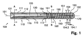
図1〜図3は、本発明による第1のガイドワイヤ100を示す。図1は、第1のガイドワイヤ100の長手方向中心軸101に沿った長手方向断面を示す。ガイドワイヤ100は、2パートの中空シャフト110を備え、前記中空シャフト110の近位部分111は、例えば中空の円筒状鋼チューブから作製されるのに対し、遠位部分115は、近位部分111に対して同軸上に配置される中空の円筒状ポリイミドチューブから作製される。中空シャフト110の近位部分111の横断面が、図2に示される。前記材料選択により、中空シャフト110の遠位部分115の弾性は、近位部分111の弾性よりも高い。
1 to 3 show a
近位部分111の遠位端部112は、内径が一定のまま遠位方向にテーパ状をなす一方で、遠位部分115の近位端部116は、近位部分111の遠位端部112に対して相補的な態様で、外径が一定のまま近位方向に円錐状に広がる。2つの部分111,115の内径同士およびさらに外径同士は、一定の直径120.1を有する連続円形円筒状管腔120が中空シャフト110中に存在するように、実質的に同一のサイズである。
The
遠位部分115の遠位端部117から、同軸上に配置された中空円筒状ワイヤコイル150が、中空シャフト110から離れるように遠位方向に延在する。ワイヤコイル150の近位端部152は、圧接により遠位部分115の遠位端部117に固定される。ワイヤコイルは、例えば約50μmのワイヤ直径を有する白金ワイヤから作製される。ワイヤコイル150の横断面が、図3に示される。ワイヤコイル150の可撓性は、中空シャフト110の遠位部分115の可撓性よりも高い。
From the
プラスチックから作製され非外傷的に丸められた半球状の付属品の形態のガイドワイヤ先端部170が、ワイヤコイルの遠位端部153上に取り付けられる。ガイドワイヤ先端部170は、例えば圧接により、ワイヤコイル150に連結することが可能である。
A
ガイドワイヤ先端部170の後に近位方向に直に連続して配置される、ワイヤコイル150の第1の巻線と第2の巻線との間、およびワイヤコイル150の第2の巻線と第3の巻線との間は、ガイドワイヤ先端部の区域において流体透過貫通開口154がワイヤコイル150中に存在するように、離間される。第1の巻線と第2の巻線との間の第1の間隔154.1、および第2の巻線と第3の巻線との間の第2の間隔154.2は、いずれの場合でも、ワイヤコイル150のワイヤ直径の0.3倍にほぼ相当する。
Between the first and second windings of the
貫通開口154は、近位方向においてガイドワイヤ先端部170に隣接するワイヤコイル150の遠位内方区域151に直に通じている。したがって、換言すれば、ワイヤコイル150の遠位内方区域151は、導入および/または除去されるべき流体のための、外方向に開いた貫通開口154を有する。ワイヤコイル150の他の巻線同士は、互いに直に接した状態で構成されるとともに、ワイヤコイル150の液密/放射線不透過性部分155を形成する。
The through
ワイヤコイル150の内径150.1は、全長にわたり実質的に一定であり、かつ中空シャフト110の内径と、または中空円筒状管腔120の直径とほぼ一致する。
The inner diameter 150.1 of the
中空シャフト110の近位部分111においては、芯ワイヤ130の近位端部131が、管腔120の境界表面上に、または中空シャフト110の内部にさらに溶接される。芯ワイヤ130の近位端部131は、中空シャフト110内において偏心的に配置される。芯ワイヤ130は、遠位部分115およびワイヤコイル150を貫通してガイドワイヤ先端部170まで延在する。芯ワイヤ130の遠位端部132は、例えば圧接により、ガイドワイヤ先端部170に連結される。
In the
芯ワイヤ130は、例えば鋼から作製され、かつ近位端部131から遠位端部132にかけて漸減する外径を有する。芯ワイヤ130の近位端部131での近位外径130.1は、ワイヤコイル150の区域における芯ワイヤの遠位外径130.2よりも大きい。ガイドワイヤ100の可撓性は、芯ワイヤ130の近位端部131からガイドワイヤ先端部170に向けて実質的に連続的に低下する。
The
芯ワイヤ130の外径130.1,130.2は、例外なく、管腔120の直径120.1よりも小さく、かつワイヤコイル150の内径150.1よりも小さい。
The outer diameters 130.1 and 130.2 of the
ワイヤコイル150の近位部分において、芯ワイヤ130は、流体透過性連結部160を介してワイヤコイル150に連結される。前記流体透過性連結部160は、例えばはんだ付けされた連結部の形態の一体的に接合された連結部である。流体透過性連結部160は、流体透過性連結部160の区域において、芯ワイヤ130に沿うチャネル状通路161を、送出および回収すべき流体の通過が自在な状態に留めるように、ガイドワイヤ100の長手方向中心軸101に対して非対称的および/または一方に偏倚するように構成される。したがって、ワイヤコイル150の遠位内方区域151は、チャネル状通路161を介して、ワイヤコイル150の近位内方区域156と連通する。横断面において、流体透過性連結部は、ワイヤコイル150の内方区域の断面範囲の約40%を占める。ワイヤコイル150の内径150.1は、流体透過性連結部160の区域において、この区域の芯ワイヤ130の近位外径130.1の約3.5倍の大きさである。
In the proximal portion of the
したがって、第1のガイドワイヤ100の管腔120は、芯ワイヤ130に沿って形成されたチャネル状通路161を介して、ワイヤコイル150の遠位内方区域151と連通し、さらに前記遠位内方区域151は、流体を送出および/または回収するための、外部方向への貫通開口154を有する。
Thus, the
図4は、長手方向中心軸201に沿った長手方向断面において、本発明による第2のガイドワイヤ200を示す。図5は、第2のガイドワイヤの流体透過性連結部260の区域の横断面を示す。
FIG. 4 shows a
第2のガイドワイヤ200は、管腔220を有する中空シャフト210を同様に有し、第2のガイドワイヤ200の中空シャフト210および管腔220は、第1のガイドワイヤ100の中空シャフト100および管腔120と実質的に同一である。同様に、第2のガイドワイヤ200は、ガイドワイヤ先端部270および芯ワイヤ230により、中空シャフト210上に固定されたワイヤコイル250を有する。ワイヤコイル250、ガイドワイヤ先端部270、および芯ワイヤ230は、第1のガイドワイヤ100の対応する部分とやはり実質的に同一である。さらに、第2のガイドワイヤ200の前記部分は、第1のガイドワイヤ100の対応する部分と同様に構成され、かつ同様に相互に固定される。したがって、第2のガイドワイヤ200のワイヤコイル250は、送出および/または回収すべき流体のための、ガイドワイヤ先端部270の直後に構成される貫通開口254をやはり有する。
The
しかしながら、第1のガイドワイヤ100とは対照的に、第2のガイドワイヤ200は、流体透過性連結部260を有し、該流体透過性連結部260は、その中に埋め込まれるとともに、送出および/または回収すべき流体のためのチャネル状通路として芯ワイヤに対して平行に延在するチューブ261と一体的に接合された連結部として構成される、流体透過性連結部260を有する。チューブ261は、例えばはんだ材料内に一体的に接合された態様で全長にわたって埋め込まれるとともに、ワイヤコイル250に連結される。
However, in contrast to the
したがって、第2のガイドワイヤ200の管腔220は、前記チューブ261を介して、ワイヤコイル250の遠位内方区域251と連通する。前記チューブ261は、チャネル状通路としての役割を果たし、芯ワイヤ230に沿って配置される。遠位内方区域251は、流体を送出および/または回収するための貫通開口254をやはり有する。
Accordingly, the
図6は、長手方向中心軸301に沿った長手方向断面において、本発明による第3のガイドワイヤ300を示す。
FIG. 6 shows a
第3のガイドワイヤ300は、管腔320を有する中空シャフト310を同様に有し、第3のガイドワイヤ300の中空シャフト310および管腔320は、第1のガイドワイヤ100の中空シャフト110および管腔120と実質的に同一である。同様に、第3のガイドワイヤ300は、ガイドワイヤ先端部370および芯ワイヤ330により、中空シャフト310に固定されたワイヤコイル350を有する。ワイヤコイル350は、同様に、例えば約50μmの直径を有する白金ワイヤから作製される。
The
しかしながら、第1のガイドワイヤ100とは対照的に、ワイヤコイル350は、互いに離間された複数の貫通開口354a,354b,354c,354dを有する。近位方向においてガイドワイヤ先端部370の直後に位置するワイヤコイル350の第1の巻線および第2の巻線は、ガイドワイヤ先端部370の区域において第1の流体透過性/放射線透過性貫通開口354aがワイヤコイル350中に存在するように、相互に離間される。
However, in contrast to the
第1の液密/放射線不透過性部分355aが、遠位方向において、第1の流体透過性貫通開口354aに隣接する。第1の液密部分355aは、例えばワイヤコイル350のうちの互いに直に接した状態の4つの巻線によって形成される。
A first liquid tight /
近位方向において、第1の液密部分355aの後には、第2の流体透過性/放射線透過性貫通開口354bが続く。該第2の流体透過性/放射線透過性貫通開口354bは、ワイヤコイル350のうちの2つの離間された巻線によって形成される。近位方向において、第2の流体透過性/放射線透過性貫通開口354bの後には、ワイヤコイル350の第2の液密/放射線不透過性部分355bが続く。第1の液密区域355aと同様に、第2の液密区域355bもまた、例えばワイヤコイル350のうちの互いに直に接した状態の4つの巻線によって形成される。
In the proximal direction, the first fluid-
近位方向において、第2の液密部分355bの後には、第3の流体透過性/放射線透過性貫通開口354cが続く。前記第3の流体透過性/放射線透過性貫通開口354cは、ワイヤコイル350の2つの離間された巻線によってやはり形成される。近位方向において、前記第3の貫通開口の後には、第3の液密/放射線不透過性部分355cが続く。前記第3の液密/放射線不透過性部分355cは、同様に、ワイヤコイル350のうちの互いに直に接した状態の4つの巻線によって形成される。
In the proximal direction, the second fluid
近位方向において、第3の液密部分355cの後には、ワイヤコイル350の2つの離間された巻線によってやはり形成される、第4の流体透過性/放射線透過性貫通開口354dが続く。
In the proximal direction, the third fluid-
前記第4の流体透過性貫通開口354dは、近位方向において、ワイヤコイルのうちの互いに直に接した状態の4つの巻線により形成される、ワイヤコイル350の第4の液密/放射線不透過性部分355dによって隣接される。
The fourth fluid permeable through-
近位方向において、ワイヤコイルの近位端部352を形成するワイヤコイル350の最後のワイヤ巻線は、中空シャフト310の遠位端部317に溶接される。
In the proximal direction, the last wire winding of the
したがって、ワイヤコイル350の全長にわたり、複数の流体透過性/放射線透過性貫通開口354a,354b,354c,354dが、規則的に互いに離間されるとともに、複数の液密/放射線不透過性部分355a,355b,355c,355dによって分離される。離間された貫通開口354a,354b,354c,354dはそれぞれ、例えば、長手方向中心軸301に対して平行な方向において測定した場合に、ワイヤコイル350のワイヤ直径の約0.5倍となる幅を有する。
Thus, over the entire length of the
第4の液密部分355dの区域において、中空シャフト310から突出しかつワイヤコイル350を貫通してガイドワイヤ先端部まで延在する芯ワイヤ370が、流体透過性連結部360を介して、ワイヤコイル350に連結される。流体透過性連結部360は、第1のガイドワイヤ100の流体透過性連結部160と実質的に同一の構成を有するとともに、例えばはんだ付けされた連結部の形態で一体的に接合された連結部として存在する。したがって、流体透過性連結部360は、流体透過性連結部360の区域において、芯ワイヤ330に沿うチャネル状通路361を、送出および回収すべき流体の通過が自在な状態に留めるように、第3のガイドワイヤ300の長手方向中心軸301に対して非対称的および/または一方に偏倚するように構成される。横断面において、流体透過性連結部は、ワイヤコイル350の内方区域の断面範囲の約40%を占める。ワイヤコイル350の内径は、流体透過性連結部360の区域において、前記区域の芯ワイヤ330の外径の約3.5倍の大きさである。
In the area of the fourth liquid-
したがって、第3のガイドワイヤ300の管腔320は、芯ワイヤ330に沿って形成されるチャネル状通路361を介して、ワイヤコイル350の遠位内方広域351と連通する。遠位内方区域351は、流体を送出および/または回収するための4つの貫通開口354a,354b,354c,354dをやはり有する。
Accordingly, the
図7および図8は、長手方向軸401に沿った長手方向断面において、および横断面において、本発明による第4のガイドワイヤ400を示す。第4のガイドワイヤ400の中空シャフト410、ワイヤコイル450、ガイドワイヤ先端部470、および芯ワイヤ430は、第1のガイドワイヤ100の対応する部分と実質的に同一である。したがって、ワイヤコイル450は流体透過性貫通開口454を有し、該流体透過性貫通開口454は近位方向においてガイドワイヤ先端部470の直後に配置され、かつ前記流体透過性貫通開口454はワイヤコイルの3つの離間された巻線により形成されるとともにワイヤコイルの遠位内方区域451と連通する。第4のワイヤコイル450の貫通開口454は、第1のガイドワイヤ100の貫通開口151と実質的に一致する。
7 and 8 show a
しかしながら、第1のガイドワイヤ100とは対照的に、第4のガイドワイヤ400は、第4のガイドワイヤ400の長手方向中心軸401に対して同軸方向において、中空シャフト410からワイヤコイル450の内方区域内に突出する中空円筒状チューブの形態の管状スタブ480をさらに有する。管状スタブ480の近位端部481は、例えば接着剤結合および/または溶接により、中空シャフト410の遠位端部417に固定される。管状スタブ480の外径は、中空シャフト410の内径およびワイヤコイル450の内径と実質的に一致する。
However, in contrast to the
管状スタブ480の近位部分は、例えば接着連結により、ワイヤコイル450の近位部分に連結される。
The proximal portion of the
管状スタブ480の遠位端部は、貫通開口454が管状スタブ480により覆われず、したがって通過自在の状態に留められるように、遠位方向において貫通開口454の直前に配置される。
The distal end of the
第4のガイドワイヤ400の芯ワイヤ430は、管状スタブ480を貫通して延在する。管状スタブ480の内径は、例外なく、この区域における芯ワイヤ430の外径よりも大きい。したがって、送出および回収すべき流体が通過し得るチャネル状通路461が、芯ワイヤ430に沿った管状スタブ480内において通過自在な状態に留められる。
The
したがって、管状スタブ480内に存在する前記チャネル状通路461により、第4のガイドワイヤ400の管腔420は、ワイヤコイル450の遠位内方区域451と連通する。前記遠位内方区域451は、流体を送出および/または回収する流体透過性貫通開口454をやはり有する。
Thus, the
図9は、血管500内に押し入れられた後の図1〜図3の第1のガイドワイヤ100を示す図である。ガイドワイヤ先端部170は、例えば薬物によって治療すべき血管500内の狭まった位置501の直ぐ前に位置する。体外に位置する(および図9に図示されない)ガイドワイヤ100の近位端部の区域において、投与すべき薬物502を、管腔120内に導入することが可能であるとともに、ガイドワイヤ先端部170の直ぐ後に位置する貫通開口154を介して血管500内に送給することが可能である。貫通開口154が、ガイドワイヤ先端部170の区域の直後に位置するため、投与すべき薬物は、治療すべき狭窄部501の区域内に比較的正確に進む。
FIG. 9 shows the
上述の実施形態は、例示的な例のみとして理解すべきであり、これらの例は、本発明の文脈(context)の範囲内において任意の所望の形態で修正することが可能である。 The above-described embodiments should be understood as illustrative examples only, and these examples can be modified in any desired form within the context of the present invention.
したがって、ガイドワイヤ100,200,300,400の全てにおいて、例えば、2パートの中空シャフト110,210,310,410を、1パートの中空シャフトと置き換えることが可能である。これらは、例えば鋼チューブの形態などで存在することが可能である。この場合には、ワイヤコイルは、例えば中空シャフトの前面上に溶接され得る。さらに、当然ながら、3つ、4つ、または5つ以上の独立した副次的部分を有するマルチパートの中空シャフトを使用することも可能である。これらのシャフトが、1パート、2パート、または3以上のパートのいずれであるかにかかわらず、中空シャフト110,210,310,410は、特に挿入性を向上させるために、例えば遠位方向にテーパ状となるように構成することも可能である。
Accordingly, in all of the
中空シャフト110の近位部分111の遠位端部区域112および/または遠位部分115の近位端部区域116もまた、別様に構成および/または連結することが可能である。例えば、2つの部分111,115が、いずれの場合においても長手方向中心軸101に対して直角に位置する環状前面を介して、当接状態で一体的に接合され、接着剤結合および/または溶接され得る。
The
同様に、ガイドワイヤ先端部170,270,370,470は、別様に構成することもまた可能であり、例えば特定用途向けに適合化することが可能である。
Similarly, the
流体透過性連結部160,260,360に加えて、芯ワイヤ130,230,330とワイヤコイル150,250,350との間に他の連結部を形成することも可能である。しかしながら、原則的には、流体透過性連結部160,260,360を完全に省くこともまた可能である。同様に、第4のガイドワイヤ400において、例えばワイヤコイルの安定性をさらに高めるためなどに、追加の流体透過性連結部を、芯ワイヤと管状スタブ480との間に形成することが可能である。
In addition to the fluid permeable connecting
第2のガイドワイヤ200の流体透過性連結部260において、例えば流体透過性断面表面積を拡大するためなどに、チューブ261に加えて他のチューブがあってもよい。
There may be other tubes in addition to the
さらに、原則的には、適切である場合には、ワイヤコイル150,250,350,450を、ガイドワイヤ先端部に向けて遠位方向にテーパ状に構成することもまた可能である。ある状況においては、これは、ガイドワイヤの挿入性を高め得る。 Furthermore, in principle, it is also possible, if appropriate, to configure the wire coils 150, 250, 350, 450 to taper distally towards the guide wire tip. In some situations, this may increase the insertability of the guidewire.
第3のガイドワイヤ300において、さらに、ワイヤコイル450の4つの貫通開口354a,354b,354c,354dよりも多数のまたは少数の貫通開口を設けることもまた可能である。したがって、例えば、ワイヤコイルの全長にわたり流体が送出および/または回収され得るように、ワイヤコイル450の全ての巻線が離間されることが考えられる。これに対応する構成は、最初の2つのガイドワイヤ100,200のワイヤコイル150,250においても可能である。
In the
第1のガイドワイヤ100において、芯ワイヤ130の近位端部131は、原則的には、中空シャフト110の遠位部分115に取り付けることもまた可能である。さらに、芯ワイヤ130は、例えば弾性の急激な変化を補償するためなどに、段階的に漸減および/または漸増する外径を有する区域を有することも可能である。しかしながら、原則的には、芯ワイヤは、全長にわたり一定の外径を有することも可能である。
In the
特定の使用にとって有利である場合には、ガイドワイヤ100,200,300,400の全てを、例えば楕円形断面などを有するように構成することもまた可能である。
If advantageous for a particular use, it is also possible to configure all of the
さらに、適切であることが明らかな場合には、中空シャフト110,210,310,410自体の上に追加の貫通開口を設けることもまた可能である。
In addition, it may also be possible to provide additional through-openings on the
結論として、ヒトおよび/または動物の中空器官内への容易な挿入が可能であり、かつさらにはヒトおよび/または動物の中空器官内の所定の箇所にて高い精度および目標設定で流体を導入および/または除去することが可能となる、新規のガイドワイヤが作製されたと言える。 In conclusion, it allows easy insertion into human and / or animal hollow organs, and even introduces fluids with high precision and targeting at predetermined locations within human and / or animal hollow organs. It can be said that a new guide wire has been created that can be removed.
100 第1のガイドワイヤ
101 長手方向中心軸
131 芯ワイヤ130の近位端部
111 中空シャフト110の近位部分
112 近位部分111の遠位端部
120 連続円形円筒状管腔
130 芯ワイヤ
156 ワイヤコイル150の近位内方区域
161 チャネル状通路
155 液密/放射線不透過性部分
151 ワイヤコイル150の遠位内方区域
154 流体透過貫通開口
153 ワイヤコイルの遠位端部
132 芯ワイヤ130の遠位端部
170 ガイドワイヤ先端部
154.1 第1の間隔
154.2 第2の間隔
150 ワイヤコイル
160 流体透過性連結部
152 ワイヤコイル150の近位端部
117 遠位部分115の遠位端部
115 中空シャフト110の遠位部分
116 遠位部分115の近位端部
110 2 パート中空シャフト
130.1 芯ワイヤ130の近位端部131の近位外径
120.1 管腔120の直径
150.1 ワイヤコイル150の内径
130.1 芯ワイヤ130の外径
130.2 芯ワイヤの遠位外径
200 第2のガイドワイヤ
201 長手方向中心軸
220 管腔
230 芯ワイヤ
261 チューブ
250 ワイヤコイル
251 ワイヤコイル250の遠位内方区域
254 貫通開口
270 ガイドワイヤ先端部
260 流体透過性連結部
210 中空シャフト
300 第3のガイドワイヤ
301 長手方向中心軸
320 管腔
330 芯ワイヤ
361 チャネル状通路
355a 第1の液密/放射線不透過性部分
355b 第2の液密/放射線不透過性部分
355c 第3の液密/放射線不透過性部分
355d 第4の液密/放射線不透過性部分
354a 第1の流体透過性/放射線透過性貫通開口
354b 第2の流体透過性/放射線透過性貫通開口
354c 第3の流体透過性/放射線透過性貫通開口
354d 第4の流体透過性/放射線透過性貫通開口
370 ガイドワイヤ先端部
351 ワイヤコイル350の遠位内方広域
350 ワイヤコイル
360 流体透過性連結部
352 ワイヤコイルの近位端部
317 中空シャフト310の遠位端部
310 中空シャフト
400 第4のガイドワイヤ
401 長手方向中心軸
420 管腔
430 芯ワイヤ
481 管状スタブ480の近位端部
461 チャネル状通路
480 管状スタブ
482 管状スタブ480の遠位端部
454 流体透過性貫通開口
470 ガイドワイヤ先端部
453 ワイヤコイル450の遠位端部
451 ワイヤコイル450の遠位内方区域
450 ワイヤコイル
417 中空シャフト410の遠位端部
410 中空シャフト
500 血管
501 血管500内の狭まった位置、治療すべき狭窄部
502 薬物
100 First guide wire
101 Longitudinal central axis
131 Proximal end of
111 Proximal part of
112 Distal end of
120 continuous circular cylindrical lumen
130 core wire
156 Proximal inward section of
161 Channel passage
155 Liquid-tight / radiopaque parts
151 Distal inner region of
154 Fluid-permeable through-opening
153 Wire coil distal end
132 Distal end of
170 Guide wire tip
154.1 First interval
154.2 Second interval
150 wire coil
160 Fluid permeable connection
152 Proximal end of
117 Distal end of
115 Distal part of
116 Proximal end of
110 2-part hollow shaft
130.1 Proximal outer diameter of
120.1 Diameter of
150.1 Inside diameter of
130.1 Outer diameter of
130.2 Distal outer diameter of core wire
200 Second guidewire
201 Longitudinal central axis
220 lumen
230 core wire
261 tubes
250 wire coil
251 Distal inner section of
254 Through-opening
270 Guide wire tip
260 Fluid permeable connection
210 hollow shaft
300 Third guidewire
301 Longitudinal central axis
320 lumens
330 core wire
361 channel passage
355a First liquid-tight / radiopaque part
355b Second liquid-tight / radiopaque part
355c 3rd liquid tight / radiopaque part
355d 4th liquid tight / radiopaque part
354a 1st fluid permeable / radioactive through aperture
354b Second fluid permeable / radioactive through aperture
354c Third fluid permeable / radioactive through aperture
354d 4th fluid permeable / radioactive through aperture
370 Guide wire tip
351 Distal inner area of
350 wire coil
360 Fluid permeable connection
352 Proximal end of wire coil
317 Distal end of
310 hollow shaft
400 4th guidewire
401 Longitudinal central axis
420 lumen
430 core wire
481 Proximal end of
461 Channel passage
480 Tubular stub
482 Distal end of
454 Fluid permeable through opening
470 Guidewire tip
453 Distal end of
451 Distal inner area of
450 wire coil
417 Distal end of
410 hollow shaft
500 blood vessels
501 Narrow position in
502 drugs
Claims (19)
a) 前記流体を送出および/または回収するための管腔(120)を有する長尺の中空シャフト(110)と、
b) 前記中空シャフト(110)の遠位端部(117)に同軸上に装着された可撓性のワイヤコイル(150)の形態の挿入補助具であって、ガイドワイヤ先端部(170)が、前記ワイヤコイルの遠位端部(153)に配置された、挿入補助具と、
c) 前記ガイドワイヤ(100)の可撓性を制御するために、前記中空シャフト(110)の前記管腔(120)内に配置された芯ワイヤ(130)であって、前記管腔(120)の外に長手方向におよび前記ワイヤコイル(150)を貫通して前記ガイドワイヤ先端部(170)まで延在する、芯ワイヤ(130)と、
d) 近位方向において前記ガイドワイヤ先端部(170)に隣接する前記ワイヤコイル(150)の遠位内方区域(151)であって、前記芯ワイヤ(130)に沿って形成される流体チャネル(151,161,155)を介して、前記中空シャフト(110)の前記管腔(120)と連通する、前記ワイヤコイル(150)の遠位内方区域(151)と、を備え、
e) 導入および/または除去すべき前記流体のための少なくとも1つの外方向に開いた貫通開口(154)を有し、
f) 少なくとも1つの貫通開口(154)を形成するために、ワイヤコイル(150)の少なくとも2つの隣接し合う巻線同士が間隔をおいて配置され、
g) 前記芯ワイヤ(450)を囲みかつ前記中空シャフト(410)の遠位端部(417)から突出する中空円筒状の管状スタブ(480)が、前記ワイヤコイル(450)の内部に部分的に延在することを特徴とするガイドワイヤ。 A guidewire (100) for a catheter configured to introduce and / or remove fluid in human and / or animal hollow organs, particularly blood vessels,
a) an elongated hollow shaft (110) having a lumen (120) for delivering and / or collecting said fluid;
b) An insertion aid in the form of a flexible wire coil (150) coaxially mounted on the distal end (117) of the hollow shaft (110), the guide wire tip (170) being An insertion aid disposed at the distal end (153) of the wire coil;
c) a core wire (130) disposed within the lumen (120) of the hollow shaft (110) to control the flexibility of the guidewire (100), wherein the lumen (120 A core wire (130) extending longitudinally and through the wire coil (150) to the guidewire tip (170);
d) A fluid channel formed along the core wire (130) in the distal inner section (151) of the wire coil (150) adjacent the guidewire tip (170) in the proximal direction. A distal inner section (151) of the wire coil (150) in communication with the lumen (120) of the hollow shaft (110) via (151, 161, 155);
e) having at least one outwardly open through opening (154) for said fluid to be introduced and / or removed;
f) at least two adjacent windings of the wire coil (150) are spaced apart to form at least one through-opening (154);
g) A hollow cylindrical tubular stub (480) that surrounds the core wire (450) and protrudes from the distal end (417) of the hollow shaft (410) is partially within the wire coil (450). A guide wire that extends into the guide.
Applications Claiming Priority (3)
| Application Number | Priority Date | Filing Date | Title |
|---|---|---|---|
| CH1506/09 | 2009-09-30 | ||
| CH01506/09A CH701913A1 (en) | 2009-09-30 | 2009-09-30 | Guidewire. |
| PCT/CH2010/000234 WO2011038522A1 (en) | 2009-09-30 | 2010-09-29 | Guide wire |
Related Child Applications (2)
| Application Number | Title | Priority Date | Filing Date |
|---|---|---|---|
| JP2015182785A Division JP2016027874A (en) | 2009-09-30 | 2015-09-16 | Guide wire |
| JP2015182786A Division JP2016027875A (en) | 2009-09-30 | 2015-09-16 | Guide wire |
Publications (3)
| Publication Number | Publication Date |
|---|---|
| JP2013505799A JP2013505799A (en) | 2013-02-21 |
| JP2013505799A5 JP2013505799A5 (en) | 2013-11-14 |
| JP5813644B2 true JP5813644B2 (en) | 2015-11-17 |
Family
ID=41571523
Family Applications (3)
| Application Number | Title | Priority Date | Filing Date |
|---|---|---|---|
| JP2012531201A Active JP5813644B2 (en) | 2009-09-30 | 2010-09-29 | Guide wire |
| JP2015182786A Pending JP2016027875A (en) | 2009-09-30 | 2015-09-16 | Guide wire |
| JP2015182785A Pending JP2016027874A (en) | 2009-09-30 | 2015-09-16 | Guide wire |
Family Applications After (2)
| Application Number | Title | Priority Date | Filing Date |
|---|---|---|---|
| JP2015182786A Pending JP2016027875A (en) | 2009-09-30 | 2015-09-16 | Guide wire |
| JP2015182785A Pending JP2016027874A (en) | 2009-09-30 | 2015-09-16 | Guide wire |
Country Status (6)
| Country | Link |
|---|---|
| US (1) | US9138565B2 (en) |
| EP (3) | EP2796161B1 (en) |
| JP (3) | JP5813644B2 (en) |
| CA (1) | CA2775946C (en) |
| CH (1) | CH701913A1 (en) |
| WO (1) | WO2011038522A1 (en) |
Families Citing this family (9)
| Publication number | Priority date | Publication date | Assignee | Title |
|---|---|---|---|---|
| US7942847B2 (en) | 2005-12-16 | 2011-05-17 | Interface Associates, Inc. | Multi-layer balloons for medical applications and methods for manufacturing the same |
| US9821141B2 (en) * | 2012-07-26 | 2017-11-21 | Twin Star Medical, Inc. | Macroporous catheter |
| EP2967614B1 (en) | 2013-03-15 | 2016-11-30 | National University of Ireland Galway | A device suitable for removing matter from inside the lumen and the wall of a body lumen |
| CN105246536B (en) * | 2013-04-05 | 2018-09-21 | J·J·加尔加诺 | Conduit tube component with segmented systems stabilisation |
| EP3419513B1 (en) * | 2016-02-26 | 2021-12-29 | Cavis Technologies AB | Pressure catheter and guide wire assembly |
| DE102016009871A1 (en) | 2016-08-12 | 2018-02-15 | Häberle Laser- und Feinwerktechnik GmbH & Co. KG | Guidewire for use in tubular medical probes, in particular for nutritional therapy |
| SE1750993A1 (en) | 2017-08-15 | 2019-02-16 | Cavis Tech Ab | Pressure catheter and guide wire assembly |
| CN113164661A (en) * | 2018-08-14 | 2021-07-23 | Nxt生物医疗有限责任公司 | Systems and methods for treatment via body drainage or injection |
| US11684759B2 (en) * | 2020-01-22 | 2023-06-27 | Abbott Cardiovascular Systems Inc. | Guidewire having varying diameters and method of making |
Family Cites Families (18)
| Publication number | Priority date | Publication date | Assignee | Title |
|---|---|---|---|---|
| ES2000247A4 (en) * | 1986-05-23 | 1988-02-01 | Sarcem Sa | CATHETER-GUIDE |
| US5050606A (en) * | 1987-09-30 | 1991-09-24 | Advanced Cardiovascular Systems, Inc. | Method for measuring pressure within a patient's coronary artery |
| US4964409A (en) | 1989-05-11 | 1990-10-23 | Advanced Cardiovascular Systems, Inc. | Flexible hollow guiding member with means for fluid communication therethrough |
| EP0313836A3 (en) | 1987-09-30 | 1991-01-23 | Advanced Cardiovascular Systems, Inc. | Pressure monitoring guidewire |
| US4953553A (en) | 1989-05-11 | 1990-09-04 | Advanced Cardiovascular Systems, Inc. | Pressure monitoring guidewire with a flexible distal portion |
| US4940062A (en) * | 1988-05-26 | 1990-07-10 | Advanced Cardiovascular Systems, Inc. | Guiding member with deflectable tip |
| US5211636A (en) * | 1990-10-31 | 1993-05-18 | Lake Region Manufacturing Co., Inc. | Steerable infusion guide wire |
| AU2643392A (en) * | 1991-09-05 | 1993-04-05 | Mayo Foundation For Medical Education And Research | Flexible tubular device for use in medical applications |
| US5322508A (en) * | 1993-04-08 | 1994-06-21 | Cordis Corporation | Guidewire fluid delivery system and method of use |
| US5554114A (en) * | 1994-10-20 | 1996-09-10 | Micro Therapeutics, Inc. | Infusion device with preformed shape |
| US5776100A (en) * | 1995-09-27 | 1998-07-07 | Interventional Innovations Corporation | Nickel titanium guide wires for occlusion and drug delivery |
| US5797876A (en) | 1995-11-27 | 1998-08-25 | Therox, Inc. | High pressure perfusion device |
| US5957899A (en) | 1995-11-27 | 1999-09-28 | Therox, Inc. | High pressure transluminal fluid delivery device |
| US5860938A (en) | 1996-03-07 | 1999-01-19 | Scimed Life Systems, Inc. | Medical pressure sensing guide wire |
| US6488637B1 (en) * | 1996-04-30 | 2002-12-03 | Target Therapeutics, Inc. | Composite endovascular guidewire |
| WO2001054761A2 (en) * | 2000-01-28 | 2001-08-02 | William Cook, Europe Aps | Endovascular medical device with plurality of wires |
| JP2002233574A (en) | 2001-02-09 | 2002-08-20 | Hanako Medical Kk | Guide wire with marker at end portion |
| US20070213689A1 (en) * | 2002-03-22 | 2007-09-13 | Grewe David D | Deflectable tip infusion guidewire |
-
2009
- 2009-09-30 CH CH01506/09A patent/CH701913A1/en not_active Application Discontinuation
-
2010
- 2010-09-29 EP EP14001969.6A patent/EP2796161B1/en active Active
- 2010-09-29 EP EP14001967.0A patent/EP2783722B1/en active Active
- 2010-09-29 WO PCT/CH2010/000234 patent/WO2011038522A1/en active Application Filing
- 2010-09-29 CA CA2775946A patent/CA2775946C/en active Active
- 2010-09-29 JP JP2012531201A patent/JP5813644B2/en active Active
- 2010-09-29 EP EP10760900.0A patent/EP2482910B1/en active Active
- 2010-09-29 US US13/499,213 patent/US9138565B2/en active Active
-
2015
- 2015-09-16 JP JP2015182786A patent/JP2016027875A/en active Pending
- 2015-09-16 JP JP2015182785A patent/JP2016027874A/en active Pending
Also Published As
| Publication number | Publication date |
|---|---|
| EP2482910B1 (en) | 2020-07-08 |
| JP2016027874A (en) | 2016-02-25 |
| US20120238872A1 (en) | 2012-09-20 |
| EP2783722A1 (en) | 2014-10-01 |
| EP2783722B1 (en) | 2019-01-16 |
| WO2011038522A1 (en) | 2011-04-07 |
| CA2775946A1 (en) | 2011-04-07 |
| CH701913A1 (en) | 2011-03-31 |
| US9138565B2 (en) | 2015-09-22 |
| EP2796161A1 (en) | 2014-10-29 |
| EP2482910A1 (en) | 2012-08-08 |
| JP2013505799A (en) | 2013-02-21 |
| JP2016027875A (en) | 2016-02-25 |
| CA2775946C (en) | 2017-11-07 |
| EP2796161B1 (en) | 2022-10-19 |
Similar Documents
| Publication | Publication Date | Title |
|---|---|---|
| JP5813644B2 (en) | Guide wire | |
| JP6840705B2 (en) | Tilted grid and method of manufacturing tilted grid | |
| JP6419773B2 (en) | Boosting catheter and related systems and methods | |
| US8197442B2 (en) | Interventional medical device system having a slotted section and radiopaque marker and method of making the same | |
| JP4308007B2 (en) | Intravascular microcatheter having a proximal shaft comprising a hypotube with a transition section | |
| JP5381703B2 (en) | Thrombus aspiration catheter | |
| CA2228346C (en) | Guidewire having a distal tip that can change its shape within a vessel | |
| ES2807348T3 (en) | Balloon catheter and support shaft for it | |
| JP2018140190A (en) | Low profile occlusion catheter | |
| JP2021184830A (en) | Radial and trans-endocardial delivery catheter | |
| EP0823261A2 (en) | Guidewire having a distal tip that can change its shape within a vessel | |
| JP2004516049A (en) | Guidewire with marker section for length evaluation | |
| KR20130061740A (en) | Distal access aspiration guide catheter | |
| JP2012228296A (en) | Catheter | |
| WO2006090707A1 (en) | Catheter | |
| JP2006271955A (en) | Guide wire | |
| JP2023517575A (en) | Neurovascular catheter with enhanced flexibility | |
| WO2014103599A1 (en) | Catheter | |
| JP2012223207A (en) | Balloon catheter | |
| JP4790366B2 (en) | Extracorporeal circulation catheter | |
| WO2005087303A1 (en) | Guidewire with hollow distal section | |
| JP2016506286A (en) | Coronary guidewire | |
| US20220152351A1 (en) | Catheter | |
| JP2015156959A (en) | Long medical instrument | |
| JP4752738B2 (en) | Medical catheter |
Legal Events
| Date | Code | Title | Description |
|---|---|---|---|
| A711 | Notification of change in applicant |
Free format text: JAPANESE INTERMEDIATE CODE: A711 Effective date: 20130111 |
|
| A521 | Request for written amendment filed |
Free format text: JAPANESE INTERMEDIATE CODE: A523 Effective date: 20130927 |
|
| A621 | Written request for application examination |
Free format text: JAPANESE INTERMEDIATE CODE: A621 Effective date: 20130927 |
|
| A977 | Report on retrieval |
Free format text: JAPANESE INTERMEDIATE CODE: A971007 Effective date: 20140728 |
|
| A131 | Notification of reasons for refusal |
Free format text: JAPANESE INTERMEDIATE CODE: A131 Effective date: 20140804 |
|
| A601 | Written request for extension of time |
Free format text: JAPANESE INTERMEDIATE CODE: A601 Effective date: 20141016 |
|
| A521 | Request for written amendment filed |
Free format text: JAPANESE INTERMEDIATE CODE: A523 Effective date: 20150204 |
|
| TRDD | Decision of grant or rejection written | ||
| A01 | Written decision to grant a patent or to grant a registration (utility model) |
Free format text: JAPANESE INTERMEDIATE CODE: A01 Effective date: 20150817 |
|
| A61 | First payment of annual fees (during grant procedure) |
Free format text: JAPANESE INTERMEDIATE CODE: A61 Effective date: 20150916 |
|
| R150 | Certificate of patent or registration of utility model |
Ref document number: 5813644 Country of ref document: JP Free format text: JAPANESE INTERMEDIATE CODE: R150 |
|
| S531 | Written request for registration of change of domicile |
Free format text: JAPANESE INTERMEDIATE CODE: R313531 |
|
| S533 | Written request for registration of change of name |
Free format text: JAPANESE INTERMEDIATE CODE: R313533 |
|
| R350 | Written notification of registration of transfer |
Free format text: JAPANESE INTERMEDIATE CODE: R350 |
|
| R250 | Receipt of annual fees |
Free format text: JAPANESE INTERMEDIATE CODE: R250 |
|
| R250 | Receipt of annual fees |
Free format text: JAPANESE INTERMEDIATE CODE: R250 |
|
| R250 | Receipt of annual fees |
Free format text: JAPANESE INTERMEDIATE CODE: R250 |
|
| R250 | Receipt of annual fees |
Free format text: JAPANESE INTERMEDIATE CODE: R250 |
|
| R250 | Receipt of annual fees |
Free format text: JAPANESE INTERMEDIATE CODE: R250 |
|
| R250 | Receipt of annual fees |
Free format text: JAPANESE INTERMEDIATE CODE: R250 |