JP5812876B2 - RFID tag - Google Patents
RFID tag Download PDFInfo
- Publication number
- JP5812876B2 JP5812876B2 JP2012004577A JP2012004577A JP5812876B2 JP 5812876 B2 JP5812876 B2 JP 5812876B2 JP 2012004577 A JP2012004577 A JP 2012004577A JP 2012004577 A JP2012004577 A JP 2012004577A JP 5812876 B2 JP5812876 B2 JP 5812876B2
- Authority
- JP
- Japan
- Prior art keywords
- tag
- rfid
- hole
- base material
- inlet
- Prior art date
- Legal status (The legal status is an assumption and is not a legal conclusion. Google has not performed a legal analysis and makes no representation as to the accuracy of the status listed.)
- Active
Links
Images


Description
本発明はRFID(Radio Frequency Identification;無線自動認識)タグにかかるもので、とくに金属製品に取り付けるためのRFIDタグに関するものである。 The present invention relates to an RFID (Radio Frequency Identification) tag, and more particularly to an RFID tag to be attached to a metal product.
従来から、ICチップおよびRFIDアンテナを有して無線によりデータの書込みおよび読取りを行うことができるRFIDインレットを備えたRFIDタグを各種物品に取り付け、これら物品ついての各種データの読み書きを行って、必要なデータ管理など諸々の分野に利用している。 Conventionally, an RFID tag equipped with an RFID inlet that has an IC chip and an RFID antenna and can wirelessly write and read data is attached to various items, and various data about these items are read and written. It is used in various fields such as data management.
しかして、上記物品が金属製である場合には、上記RFIDタグが物品に近接しすぎた状態で取り付けられると、データ通信に支障が生じやすいという問題がある。
この問題を解消するために、上記RFIDインレットの保持部分を折曲げ部において折り曲げることにより他の部分から離反させ、金属表面から旗のように起立させるようにしたRFIDタグがある。
Therefore, when the article is made of metal, if the RFID tag is attached in a state where it is too close to the article, there is a problem that data communication is likely to be hindered.
In order to solve this problem, there is an RFID tag in which a holding portion of the RFID inlet is bent at a bent portion so that the RFID inlet is separated from other portions to stand like a flag from a metal surface.
しかしながら、このようなRFIDタグは、紙製であるとともに、折曲げ部が固定されていないために安定性がなく、その起立状態が不安定で、RFIDタグの取付け条件によってデータ通信性能に差が出てしまうとともに、長期間の使用および耐環境性に問題がある。
さらに、RFIDタグを金属製品に取り付けるために両面テープなどを用いているために、両面テープで固定困難な表面を有する製品の場合には使用することができないという問題がある。
However, such an RFID tag is made of paper and is not stable because the bent portion is not fixed, its standing state is unstable, and there is a difference in data communication performance depending on the mounting condition of the RFID tag. It has a problem in long-term use and environmental resistance.
Furthermore, since a double-sided tape or the like is used to attach the RFID tag to a metal product, there is a problem that the product cannot be used in the case of a product having a surface that is difficult to fix with the double-sided tape.
本発明は以上のような諸問題にかんがみなされたもので、RFIDタグを取り付ける物品が金属製であっても、データ通信に支障がないようにしたRFIDタグを提供することを課題とする。 The present invention has been considered in view of the above problems, and an object of the present invention is to provide an RFID tag that does not hinder data communication even if an article to which the RFID tag is attached is made of metal.
また本発明は、物品に対してRFIDインレットを起立離間した状態に安定して保持可能なRFIDタグを提供することを課題とする。 Another object of the present invention is to provide an RFID tag that can stably hold an RFID inlet in an upright state with respect to an article.
また本発明は、長期間の使用にあたっても、RFIDタグの起立状態を安定性良好に維持可能であるとともに耐環境性に優れたRFIDタグを提供することを課題とする。 Another object of the present invention is to provide an RFID tag that can maintain the standing state of the RFID tag with good stability and has excellent environmental resistance even when used for a long period of time.
また本発明は、RFIDタグの屈曲部に安定性を持たせることができるRFIDタグを提供することを課題とする。 Moreover, this invention makes it a subject to provide the RFID tag which can give stability to the bending part of an RFID tag.
また本発明は、廉価に生産可能なRFIDタグを提供することを課題とする。 Another object of the present invention is to provide an RFID tag that can be produced at low cost.
すなわち本発明は、RFIDタグの取付け固定に紐状の結束バンドを用いること、この結束バンドのヘッド部にRFIDタグを当接させることによりRFIDタグを屈曲させて、金属製品その他の取付け製品の表面から起立可能とすることに着目したもので、本発明は、タグ基材と、このタグ基材に装備するとともにICチップおよびRFIDアンテナを有して無線によるデータ通信が可能なRFIDインレットと、を有するRFIDタグであって、上記タグ基材は、単層の基材からこれを構成するとともに、上記タグ基材に上記RFIDインレットを取り付け、上記タグ基材には、ストラップ状のバンド本体、このバンド本体の一方端部に形成したヘッド部およびこのバンド本体の他方端部に形成したテール部を有するとともに、このテール部を上記ヘッド部の貫通係合孔に挿通係合して当該RFIDタグを物品に取り付け可能な結束バンドを挿通する貫通孔を形成してあり、この貫通孔は、この結束バンドの上記ヘッド部より小さくこれを形成し、上記タグ基材は、この貫通孔を境にして、上記物品に対して上記RFIDインレットを起立させるための起立用基部領域と、上記RFIDインレットを備えるとともにこの起立用基部領域から起立可能なインレット保持領域と、にこれを画成していることを特徴とするRFIDタグである。 That is, the present invention uses a string-like binding band for mounting and fixing an RFID tag, and bends the RFID tag by bringing the RFID tag into contact with the head portion of the binding band, so that the surface of a metal product or other mounting product is used. In the present invention, a tag base material and an RFID inlet equipped with the tag base material and having an IC chip and an RFID antenna and capable of wireless data communication are provided. The RFID tag has a single-layer base material, and the RFID base material is attached to the tag base material. The tag base material has a strap-shaped band main body, The head has a head formed at one end of the band body and a tail formed at the other end of the band body. A through hole is formed through which a binding band capable of attaching the RFID tag to an article is inserted by being inserted into and engaged with a through engagement hole of the head portion, and the through hole is formed by the head portion of the binding band. The tag base is formed smaller, and the tag base includes a standing base region for raising the RFID inlet with respect to the article with the through hole as a boundary, and the standing base with the RFID inlet. The RFID tag is characterized by defining an inlet holding region that can stand up from the region.
上記貫通孔は、上記タグ基材の厚さ方向の第1の貫通孔と、この第1の貫通孔に縦方向に並列して異なる位置に形成した上記タグ基材の厚さ方向の第2の貫通孔と、からなることができる。 The through hole includes a first through hole in the thickness direction of the tag base material and a second in the thickness direction of the tag base material formed at a different position in parallel with the first through hole in the vertical direction. Through-holes.
上記タグ基材は、上記貫通孔の部分において屈曲可能であることができる。 The tag base material can be bent at the portion of the through hole.
上記結束バンドの上記ヘッド部に上記タグ基材が乗り上げることにより、上記RFIDインレットが上記物品から離反可能であることができる。 When the tag base material rides on the head portion of the binding band, the RFID inlet can be separated from the article.
上記結束バンドの上記テール部が、上記RFIDインレットを上記物品から離反する方向に上記タグ基材を付勢可能であることができる。 The tail portion of the binding band may be able to bias the tag base material in a direction in which the RFID inlet is separated from the article.
上記貫通孔は、上記タグ基材において互いに横方向に並列して少なくともその複数個を形成していることができる。 In the tag base material, at least a plurality of the through holes may be formed in parallel with each other in the lateral direction.
上記タグ基材は、軟質材料あるいは硬質材料のいずれかを選択可能である。 As the tag base material, either a soft material or a hard material can be selected.
本発明によるRFIDタグにおいては、タグ基材に貫通孔を形成しておき、この貫通孔を境にしてタグ基材のいずれか一方の領域(インレット保持領域)にRFIDインレットを設け、結束バンドをこの貫通孔に挿通してこの結束バンドを用いてRFIDタグを物品に取り付けることにより、タグ基材(RFIDインレット)を物品の表面から起立した姿勢を保持可能としたので、物品が金属製の場合であっても、RFIDインレットが物品の表面から離間した状態を安定して確実に保持可能であり、長期間にわたってデータ通信機能を維持可能で、耐環境性も良好なRFIDタグとすることができる。
さらに、タグ基材を単層の基材により構成するようにしたので、この基材の材料を任意に選択することによってタグ基材に必要な弾性および柔軟性さらには耐環境性を安価に付与可能であり、タグ基材および貫通孔の打抜き工程も低コストで実行可能である。
In the RFID tag according to the present invention, a through hole is formed in the tag base material, an RFID inlet is provided in any one region (inlet holding region) of the tag base material with this through hole as a boundary, and a binding band is formed. When the article is made of metal because the tag base (RFID inlet) can be held upright from the surface of the article by attaching the RFID tag to the article using this binding band through the through-hole. Even so, it is possible to stably and reliably hold the RFID inlet separated from the surface of the article, maintain the data communication function for a long period of time, and make the RFID tag excellent in environmental resistance. .
Furthermore, since the tag base material is composed of a single layer base material, the elasticity, flexibility, and environmental resistance required for the tag base material can be provided at a low cost by selecting the material of this base material arbitrarily. It is possible to perform the punching process of the tag base material and the through hole at a low cost.
本発明は、結束バンドをタグ基材の貫通孔に挿通して金属製品その他の物品にRFIDタグを取り付けるようにしたので、RFIDインレットを物品の表面から離間した状態で長期にわたって安定かつ確実に取り付けておくことができ、そのデータ通信機能を保障可能なRFIDタグを実現した。 In the present invention, since the RFID band is attached to the metal product or other article by inserting the binding band through the through hole of the tag base material, the RFID inlet is stably and reliably attached over a long period of time while being separated from the surface of the article. The RFID tag that can guarantee the data communication function is realized.
つぎに本発明の第1の実施例によるRFIDタグ1を図1ないし図8にもとづき説明する。
図1は、RFIDタグ1の平面図、図2は、図1のII−II線断面図、図3は、図1のIII−III線断面図であって、RFIDタグ1は、タグ基材2と、RFIDインレット3と、を有する。
Next, an RFID tag 1 according to a first embodiment of the present invention will be described with reference to FIGS.
1 is a plan view of the RFID tag 1, FIG. 2 is a cross-sectional view taken along the line II-II of FIG. 1, FIG. 3 is a cross-sectional view taken along the line III-III of FIG. 2 and the
タグ基材2は、所定の柔軟性ないし弾性、および剛性を有する、たとえば合成樹脂製のシート基材であって、その内部にRFIDインレット3を備えている。
The
RFIDインレット3は、たとえばポリエチレンテレフタレートないしその積層フィルムなどによるインレット基材4と、ICチップ5およびRFIDアンテナ6と、を有して無線によるデータ通信が可能である。
RFIDインレット3は、たとえばUHF帯(300MHz〜3GHz(好ましくは860〜960MHz、さらに具体的には、433MHz、900MHz、915〜928MHz、950〜958MHz)やマイクロ波(1〜30GHz、具体的には2.45GHz)、HF帯(3MHz〜30MHz(好ましくは13.56MHz))あるいは135kHz以下など、その他、所定の周波数帯の電波および電磁的作用などにより、RFIDアンテナ6を介してICチップ5に必要なデータの無線による読み取りおよび書き込み(データ通信)を行う。
ただし、それぞれの使用電波に応じてICチップ5およびRFIDアンテナ6の具体的構成を適正なものとしている。
とくにUHF帯(たとえば、860〜960MHz)レベルの波長を有する電波を使用するものでは、その通信距離が通常は5〜10m程度であり、各種の分野における応用が期待されている。
The
The
However, the specific configurations of the
In particular, in the case of using a radio wave having a wavelength in the UHF band (for example, 860 to 960 MHz), the communication distance is usually about 5 to 10 m, and applications in various fields are expected.
タグ基材2には、RFIDインレット3の領域を避けた位置に、結束バンド7(図5および図6、後述)を挿通するための貫通孔8を形成してある。
貫通孔8は、タグ基材2の厚さ方向に貫通して形成した、開口形状が細長矩形状(図1参照)の第1の貫通孔8Aと、この第1の貫通孔8Aに縦方向に並列して異なる位置に形成したタグ基材2の厚さ方向の、同様に細長矩形状の第2の貫通孔8Bと、からなる。なお、第1の貫通孔8Aおよび第2の貫通孔8Bは、上記結束バンド7のテール部17およびバンド本体15が挿通可能であれば、スリット状にこれを形成することもできる。
タグ基材2は、貫通孔8(第1の貫通孔8A)を境にして、物品に対してRFIDインレット3を起立離反させるための起立用基部領域2Aと、RFIDインレット3を備えるとともにこの起立用基部領域2Aから起立可能なインレット保持領域2Bと、にこれを画成している。
In the
The
The
さらに、タグ基材2は、所定の柔軟性ないし弾性および剛性を有するため、貫通孔8(第1の貫通孔8A)の部分、具体的には第1の貫通孔8Aの開口長さ方向に沿った屈曲部9において屈曲可能である。
なお、この屈曲性を確保するために、必要に応じて、第1の貫通孔8Aの横方向部分に屈曲部9に沿ってあらかじめ切れ目あるいは折れ線10(図1中、仮想線)を形成しておいてもよい。
図1に示すように、起立用基部領域2Aは、屈曲部9より図中、下方に位置する領域であり、インレット保持領域2Bは、屈曲部9より上方に位置する領域である。
Furthermore, since the
In order to ensure this flexibility, a cut line or a broken line 10 (imaginary line in FIG. 1) is formed in advance along the bent portion 9 in the lateral direction portion of the first through
As shown in FIG. 1, the standing
図2および図3に示すRFIDタグ1(タグ基材2)の断面構造は、単層構造であって、タグ基材2のいずれか一方の面(図示の例では裏面)に接着剤11などによってRFIDインレット3を取り付けている。
図4は、RFIDタグ1の、図3と同様の分解断面図であって、タグ基材2は、単層の基材たとえば、軟質材料として、軟質塩化ビニール材その他任意のものを採用することにより、RFIDタグ1としての柔軟性ないし弾性を確保するとともに比較的廉価に製造可能である。もちろん、PETのような硬質材料を採用することにより必要な剛性を確保することもできる。
The cross-sectional structure of the RFID tag 1 (tag base material 2) shown in FIG. 2 and FIG. 3 is a single-layer structure, and the adhesive 11 or the like is attached to any one surface (the back surface in the illustrated example) of the
FIG. 4 is an exploded cross-sectional view of the RFID tag 1 similar to that of FIG. 3, and the
なお図4に仮想線で示すように、RFIDインレット3を被覆するようにラベル12を貼り付けて、RFIDインレット3を保護するとともに、RFIDインレット3が保持する管理情報に関するバーコードその他によるデータをラベル12上に表示しておくことができる。
また、ラベル12の代わりに保護フィルム13をRFIDインレット3に積層被覆することもできるし、ラベル12をタグ基材2の表面側に貼り付けることもできる。
さらに、RFIDインレット3にラベル12を積層した構成の、いわゆるRFIDラベルを帯状の台紙に仮着してプリンター(ともに図示せず)に装填し、必要に応じて可変情報をラベル12上に印字可能とするとともに、印字したRFIDラベルをタグ基材2に貼り付けるように構成することもできる。また、プリンターで印字する際に、ICチップ5にデータを書き込んでもよい。
As shown by a virtual line in FIG. 4, a
Further, instead of the
Furthermore, a so-called RFID label constructed by laminating a
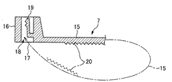
図5は、結束バンド7の側面図、図6は、結束バンド7の要部拡大断面図であって、結束バンド7としては、一般に入手可能であって、たとえばナイロンなどによりこれを構成しているもので、所定の長さを有するストラップ状のバンド本体15と、このバンド本体15の一方端部に形成した膨出形状のヘッド部16と、このバンド本体15の他方端部に形成したテーパー状のテール部17と、を有する。
FIG. 5 is a side view of the
とくに図6に示すように、ヘッド部16には、貫通係合孔18を形成し、貫通係合孔18内に固定用弾性係合突起19を形成している。
In particular, as shown in FIG. 6, a through
バンド本体15の一方の面には、固定用弾性係合突起19に係合して結束バンド7全体を任意の円周長さのリング状に締め付けて固定可能とするための凹凸形状の帯状係合部20を形成してある。
また、テール部17の一方の面には、このテール部17をつまみやすくするための凹凸部21を形成してある。
したがって、テール部17をまずRFIDタグ1の第1の貫通孔8Aさらに第2の貫通孔8Bに挿通するとともに、ヘッド部16の貫通係合孔18に挿通し、固定用弾性係合突起19に帯状係合部20の任意の部位を係合して、バンド本体15を所定の円周長さのリング状とすることにより、RFIDタグ1を物品(金属製品M、図7、後述)に取り付け可能である。
On one surface of the band
Further, an
Therefore, the
ただし、前記貫通孔8(第1の貫通孔8A、第2の貫通孔8B、図1、図3)は、結束バンド7のヘッド部16より小さくこれを形成することが必要である。
However, the through hole 8 (the first through
こうした構成のRFIDタグ1において、結束バンド7を用いてRFIDタグ1を任意の物品(たとえば金属製品M)に取り付けることができる。
すなわち、図7は、結束バンド7を用いてRFIDタグ1を任意の金属製品Mに取り付ける状態の途中を示す側面図、図8は、結束バンド7を用いてRFIDタグ1を金属製品Mに取り付けた状態を示す側面図である。
図7に示すように、結束バンド7をそのテール部17からタグ基材2の貫通孔8(まず第1の貫通孔8A、ついで第2の貫通孔8B)に挿通した状態で、バンド本体15を金属製品Mに掛け回し、テール部17をヘッド部16の貫通係合孔18に挿通してゆく。
In the RFID tag 1 having such a configuration, the RFID tag 1 can be attached to an arbitrary article (for example, the metal product M) using the
That is, FIG. 7 is a side view showing a state in which the RFID tag 1 is attached to an arbitrary metal product M using the
As shown in FIG. 7, the band
ついで図8に示すように、テール部17をヘッド部16に対してさらに引き出すように引っ張り、リング状となったバンド本体15により金属製品Mを締め付けるとともに、結束バンド7のヘッド部16にタグ基材2を乗り上げさせることによって、第1の貫通孔8Aと第2の貫通孔8Bとの間に位置する起立用基部領域2Aが金属製品Mの外表面に密着するとともに、インレット保持領域2Bが屈曲部9の部分で屈曲して金属製品Mから起立する状態となるので、インレット保持領域2B内にあるRFIDインレット3が金属製品Mから離反するように、RFIDタグ1を金属製品Mに取り付けることができる。したがって、RFIDインレット3が金属製品Mから離間した状態を保つため、データ通信機能を維持可能である。
Next, as shown in FIG. 8, the
ただし、ヘッド部16における固定用弾性係合突起19および凹凸形状の帯状係合部20の互いの係合状態が保持されているため、結束バンド7のヘッド部16にタグ基材2が乗り上げた状態を固定されることになり、RFIDインレット3が金属製品Mから離反した状態を安定して確実に実現可能である。
However, since the engagement state of the fixing
また、バンド本体16ないしテール部17には所定の剛性があるため、結束バンド7のテール部17が、インレット保持領域2B(RFIDインレット3)を金属製品Mからさらに離反する方向にタグ基材2(インレット保持領域2B)を付勢することができるので、ヘッド部16によるインレット保持領域2Bの起立姿勢を補助的に維持可能である。
なお、テール部17が長すぎる場合には、必要に応じてその先端部分を切り離すこともできる。
Further, since the band
In addition, when the
なお本発明においては、貫通孔8の第2の貫通孔8Bに結束バンド7(テール部17)を挿通することなく、第1の貫通孔8Aのみに挿通して、上述と同様にして金属製品MにRFIDタグ1を取り付けることもできる。
In the present invention, the metal product is inserted in the same way as described above by inserting only the first through
さらに、貫通孔8として第1の貫通孔8Aのみを形成しておくこともできる。
すなわち、図9は、本発明の第2の実施例によるRFIDタグ30の平面図であって、RFIDタグ30においては、タグ基材2に単一の貫通孔8(たとえば第1の貫通孔8A)のみを形成してある。
その他の構造については、第1の実施例によるRFIDタグ1と事実上同一であるので、同一部分に同一符号を付して、その詳述はこれを省略する。
Furthermore, only the first through
That is, FIG. 9 is a plan view of an
Since the other structure is practically the same as the RFID tag 1 according to the first embodiment, the same parts are denoted by the same reference numerals, and detailed description thereof is omitted.
こうした構成のRFIDタグ30においても、RFIDタグ1(第1の実施例、図1)と同様に、結束バンド7を用いてRFIDタグ30を任意の金属製品Mに取り付けることができる。
すなわち、図10は、結束バンド7を用いてRFIDタグ30を金属製品Mに取り付けた状態を示す側面図である。
結束バンド7をそのテール部17からタグ基材2の貫通孔8(第1の貫通孔8A)に挿通した状態で、バンド本体15を金属製品Mに掛け回し、テール部17をヘッド部16の貫通係合孔18に挿通してゆき、図10に示すように、テール部17をヘッド部16に対してさらに引き出すように引っ張り、リング状となったバンド本体15により金属製品Mを締め付けるとともに、結束バンド7のヘッド部16にタグ基材2を乗り上げさせることにより、起立用基部領域2Aが金属製品Mの外表面に密着するとともに、インレット保持領域2Bが屈曲部9の部分で屈曲して金属製品Mから起立する状態となるので、RFIDインレット3が金属製品Mから離反するようにRFIDタグ30を金属製品Mに取り付けることができる。
Also in the
That is, FIG. 10 is a side view showing a state where the
In a state where the
ただし、図7および図8にもとづいて既述したと同様に、ヘッド部16における固定用弾性係合突起19および凹凸形状の帯状係合部20の互いの係合状態が保持されているため、結束バンド7のヘッド部16にタグ基材2が乗り上げた状態を固定されることになり、RFIDインレット3が金属製品Mから離反した状態を安定して確実に実現可能である。この場合、厚さ方向貫通孔8Aは、結束バンド7のバンド本体15の断面に近いサイズとし、ゆるみにくくしておくことが望ましい。
However, as already described with reference to FIGS. 7 and 8, since the engagement state of the fixing
また同様に、バンド本体16ないしテール部17には所定の剛性があるため、結束バンド7のテール部17が、インレット保持領域2B(RFIDインレット3)を金属製品Mからさらに離反する方向にタグ基材2を付勢することができるので、ヘッド部16によるインレット保持領域2Bの起立姿勢を補助的に維持可能である。
Similarly, since the
本発明において、タグ基材2の形状はもちろん、貫通孔8の形状や向き、および位置や数は、RFIDインレット3のRFIDアンテナ6の大きさないし広さ、金属製品Mの形状や大きさ、結束バンド7の種類などに応じて任意に設計可能である。
たとえば図11は、本発明の第3の実施例によるRFIDタグ40の平面図であって、RFIDタグ40において、貫通孔8(第1の貫通孔8Aおよび第2の貫通孔8B)は、タグ基材2において前記屈曲部9に沿って互いに横方向に並列して少なくともその複数個(図示の例では、二個)を形成しているものである。
他の構成については、既述のRFIDタグ1(第1の実施例、図1)と事実上同一である。
In the present invention, the shape, orientation, position, and number of the through
For example, FIG. 11 is a plan view of an
Other configurations are substantially the same as the RFID tag 1 described above (first embodiment, FIG. 1).
こうした構成のRFIDタグ40においても、それぞれの貫通孔8に結束バンド7を挿通係合することができ、RFIDタグ40(とくにそのRFIDアンテナ6)が横方向に広がる大きさを有していても、必要な金属製品Mに安定して確実に取り付けるとともに、インレット保持領域2B(RFIDインレット3)を金属製品Mから離反した状態で起立させておくことができ、通信距離を延ばすことも可能である。
Even in the
1 RFIDタグ(第1の実施例、図1)
2 タグ基材
2A タグ基材2の起立用基部領域
2B タグ基材2のインレット保持領域
3 RFIDインレット
4 インレット基材
5 ICチップ
6 RFIDアンテナ
7 結束バンド(図5、図6)
8 貫通孔
8A 貫通孔8の第1の貫通孔
8B 貫通孔8の第2の貫通孔
9 屈曲部(図1、図9、図11)
10 切れ目あるいは折れ線
11 接着剤(図4)
12 ラベル
13 保護フィルム
15 結束バンド7のバンド本体
16 結束バンド7のヘッド部
17 結束バンド7のテール部
18 貫通係合孔
19 固定用弾性係合突起
20 帯状係合部
21 凹凸部
30 RFIDタグ(第2の実施例、図9)
40 RFIDタグ(第3の実施例、図11)
M 金属製品(物品、図7、図8、図10)
1 RFID tag (first embodiment, FIG. 1)
2
8 Through-
10 Cut or broken
DESCRIPTION OF
40 RFID tag (third embodiment, FIG. 11)
M metal products (articles, FIGS. 7, 8, and 10)
Claims (6)
このタグ基材に装備するとともにICチップおよびRFIDアンテナを有して無線によるデータ通信が可能なRFIDインレットと、を有するRFIDタグであって、
前記タグ基材は、単層の基材からこれを構成するとともに、
前記タグ基材に前記RFIDインレットを取り付け、
前記タグ基材には、ストラップ状のバンド本体、このバンド本体の一方端部に形成したヘッド部およびこのバンド本体の他方端部に形成したテール部を有するとともに、このテール部を前記ヘッド部の貫通係合孔に挿通係合して当該RFIDタグを物品に取り付け可能な結束バンドを挿通する貫通孔を形成してあり、
この貫通孔は、この結束バンドの前記ヘッド部より小さくこれを形成し、
前記タグ基材は、この貫通孔を境にして、
前記物品に対して前記RFIDインレットを起立させるための起立用基部領域と、
前記RFIDインレットを備えるとともにこの起立用基部領域から起立可能なインレット保持領域と、にこれを画成していることを特徴とするRFIDタグ。 A tag substrate;
An RFID tag equipped with the tag base and having an IC chip and an RFID antenna and capable of wireless data communication,
The tag base material is composed of a single layer base material,
Attaching the RFID inlet to the tag base material,
The tag base member has a strap-shaped band main body, a head portion formed at one end of the band main body, and a tail portion formed at the other end of the band main body. A through-hole is formed through which a binding band that can be attached to the article is inserted and engaged with the through-engagement hole.
This through hole forms this smaller than the head part of this binding band,
The tag base material, with this through hole as a boundary,
Standing base region for raising the RFID inlet with respect to the article;
An RFID tag comprising the RFID inlet and defining an inlet holding region capable of rising from the standing base region.
Priority Applications (1)
| Application Number | Priority Date | Filing Date | Title |
|---|---|---|---|
| JP2012004577A JP5812876B2 (en) | 2012-01-13 | 2012-01-13 | RFID tag |
Applications Claiming Priority (1)
| Application Number | Priority Date | Filing Date | Title |
|---|---|---|---|
| JP2012004577A JP5812876B2 (en) | 2012-01-13 | 2012-01-13 | RFID tag |
Publications (2)
| Publication Number | Publication Date |
|---|---|
| JP2013143117A JP2013143117A (en) | 2013-07-22 |
| JP5812876B2 true JP5812876B2 (en) | 2015-11-17 |
Family
ID=49039634
Family Applications (1)
| Application Number | Title | Priority Date | Filing Date |
|---|---|---|---|
| JP2012004577A Active JP5812876B2 (en) | 2012-01-13 | 2012-01-13 | RFID tag |
Country Status (1)
| Country | Link |
|---|---|
| JP (1) | JP5812876B2 (en) |
Families Citing this family (1)
| Publication number | Priority date | Publication date | Assignee | Title |
|---|---|---|---|---|
| JP5868759B2 (en) * | 2012-03-29 | 2016-02-24 | サトーホールディングス株式会社 | RFID tag and method of attaching the same |
-
2012
- 2012-01-13 JP JP2012004577A patent/JP5812876B2/en active Active
Also Published As
| Publication number | Publication date |
|---|---|
| JP2013143117A (en) | 2013-07-22 |
Similar Documents
| Publication | Publication Date | Title |
|---|---|---|
| JP5904798B2 (en) | RFID tag and method of attaching the same | |
| JP4913529B2 (en) | RFID media | |
| EP2754100B1 (en) | Rfid device with elongated structure | |
| US10733495B2 (en) | Wearable RFID device | |
| JP2019016330A (en) | Rfid tag label and rfid tag label continuous body | |
| JP2010128517A (en) | Ic tag label | |
| JP5812876B2 (en) | RFID tag | |
| KR101262527B1 (en) | Radio tag and method for manufacturing radio tag | |
| JP5868759B2 (en) | RFID tag and method of attaching the same | |
| JP5812875B2 (en) | RFID tag and method of attaching the same | |
| US20200175347A1 (en) | Multi-configuration label | |
| JP5351580B2 (en) | RFID tag for luggage and method for attaching the same | |
| JP2005339013A (en) | Rfid tag | |
| JP5257018B2 (en) | IC tag | |
| KR20220098033A (en) | Antenna for Smart Consumables/Identifier Labels and Smart Consumables/Identifier Labels | |
| JP2014112132A (en) | Ic tag having binding band | |
| JP6513543B2 (en) | RFID tag and method of attaching the same | |
| JP2007102047A (en) | Tag for commodity management | |
| JP2007079831A (en) | Attachment structure of ic tag and label with ic tag | |
| JP2009271741A (en) | Tag holder | |
| JP2018106576A (en) | IC tag holder | |
| KR100802503B1 (en) | Radio frequency identification tag for extending to a various sides | |
| JP5171562B2 (en) | RFID label sheet and RFID label | |
| JP2009110342A (en) | Ic tag holder and ic tag device | |
| JP2012234309A (en) | L-shaped ic tag for book |
Legal Events
| Date | Code | Title | Description |
|---|---|---|---|
| A711 | Notification of change in applicant |
Free format text: JAPANESE INTERMEDIATE CODE: A712 Effective date: 20130418 |
|
| A621 | Written request for application examination |
Free format text: JAPANESE INTERMEDIATE CODE: A621 Effective date: 20150108 |
|
| A977 | Report on retrieval |
Free format text: JAPANESE INTERMEDIATE CODE: A971007 Effective date: 20150909 |
|
| TRDD | Decision of grant or rejection written | ||
| A01 | Written decision to grant a patent or to grant a registration (utility model) |
Free format text: JAPANESE INTERMEDIATE CODE: A01 Effective date: 20150915 |
|
| A61 | First payment of annual fees (during grant procedure) |
Free format text: JAPANESE INTERMEDIATE CODE: A61 Effective date: 20150915 |
|
| R150 | Certificate of patent or registration of utility model |
Ref document number: 5812876 Country of ref document: JP Free format text: JAPANESE INTERMEDIATE CODE: R150 |
|
| R250 | Receipt of annual fees |
Free format text: JAPANESE INTERMEDIATE CODE: R250 |
|
| R250 | Receipt of annual fees |
Free format text: JAPANESE INTERMEDIATE CODE: R250 |
|
| R250 | Receipt of annual fees |
Free format text: JAPANESE INTERMEDIATE CODE: R250 |
|
| R250 | Receipt of annual fees |
Free format text: JAPANESE INTERMEDIATE CODE: R250 |
|
| R250 | Receipt of annual fees |
Free format text: JAPANESE INTERMEDIATE CODE: R250 |
|
| R250 | Receipt of annual fees |
Free format text: JAPANESE INTERMEDIATE CODE: R250 |