JP5811363B2 - Rotating electrical machine control device and electric power steering device using the same - Google Patents
Rotating electrical machine control device and electric power steering device using the same Download PDFInfo
- Publication number
- JP5811363B2 JP5811363B2 JP2013050422A JP2013050422A JP5811363B2 JP 5811363 B2 JP5811363 B2 JP 5811363B2 JP 2013050422 A JP2013050422 A JP 2013050422A JP 2013050422 A JP2013050422 A JP 2013050422A JP 5811363 B2 JP5811363 B2 JP 5811363B2
- Authority
- JP
- Japan
- Prior art keywords
- command value
- current
- power supply
- rotating electrical
- electrical machine
- Prior art date
- Legal status (The legal status is an assumption and is not a legal conclusion. Google has not performed a legal analysis and makes no representation as to the accuracy of the status listed.)
- Expired - Fee Related
Links
- 238000001514 detection method Methods 0.000 claims description 24
- 238000004804 winding Methods 0.000 claims description 3
- 238000006243 chemical reaction Methods 0.000 description 8
- 230000007613 environmental effect Effects 0.000 description 7
- 230000006378 damage Effects 0.000 description 3
- 230000020169 heat generation Effects 0.000 description 3
- 206010037660 Pyrexia Diseases 0.000 description 2
- 238000010586 diagram Methods 0.000 description 2
- 230000005669 field effect Effects 0.000 description 2
- 238000006073 displacement reaction Methods 0.000 description 1
- 238000000034 method Methods 0.000 description 1
- 239000004065 semiconductor Substances 0.000 description 1
Images
Classifications
-
- H—ELECTRICITY
- H02—GENERATION; CONVERSION OR DISTRIBUTION OF ELECTRIC POWER
- H02P—CONTROL OR REGULATION OF ELECTRIC MOTORS, ELECTRIC GENERATORS OR DYNAMO-ELECTRIC CONVERTERS; CONTROLLING TRANSFORMERS, REACTORS OR CHOKE COILS
- H02P6/00—Arrangements for controlling synchronous motors or other dynamo-electric motors using electronic commutation dependent on the rotor position; Electronic commutators therefor
- H02P6/28—Arrangements for controlling current
-
- B—PERFORMING OPERATIONS; TRANSPORTING
- B62—LAND VEHICLES FOR TRAVELLING OTHERWISE THAN ON RAILS
- B62D—MOTOR VEHICLES; TRAILERS
- B62D5/00—Power-assisted or power-driven steering
- B62D5/04—Power-assisted or power-driven steering electrical, e.g. using an electric servo-motor connected to, or forming part of, the steering gear
- B62D5/0457—Power-assisted or power-driven steering electrical, e.g. using an electric servo-motor connected to, or forming part of, the steering gear characterised by control features of the drive means as such
- B62D5/046—Controlling the motor
-
- B—PERFORMING OPERATIONS; TRANSPORTING
- B62—LAND VEHICLES FOR TRAVELLING OTHERWISE THAN ON RAILS
- B62D—MOTOR VEHICLES; TRAILERS
- B62D5/00—Power-assisted or power-driven steering
- B62D5/04—Power-assisted or power-driven steering electrical, e.g. using an electric servo-motor connected to, or forming part of, the steering gear
- B62D5/0457—Power-assisted or power-driven steering electrical, e.g. using an electric servo-motor connected to, or forming part of, the steering gear characterised by control features of the drive means as such
- B62D5/0481—Power-assisted or power-driven steering electrical, e.g. using an electric servo-motor connected to, or forming part of, the steering gear characterised by control features of the drive means as such monitoring the steering system, e.g. failures
-
- H—ELECTRICITY
- H02—GENERATION; CONVERSION OR DISTRIBUTION OF ELECTRIC POWER
- H02P—CONTROL OR REGULATION OF ELECTRIC MOTORS, ELECTRIC GENERATORS OR DYNAMO-ELECTRIC CONVERTERS; CONTROLLING TRANSFORMERS, REACTORS OR CHOKE COILS
- H02P29/00—Arrangements for regulating or controlling electric motors, appropriate for both AC and DC motors
- H02P29/02—Providing protection against overload without automatic interruption of supply
- H02P29/032—Preventing damage to the motor, e.g. setting individual current limits for different drive conditions
Description
本発明は、回転電機の駆動を制御する回転電機制御装置、および、これを用いた電動パワーステアリング装置に関する。 The present invention relates to a rotating electrical machine control device that controls driving of a rotating electrical machine, and an electric power steering device using the same.
従来、電源からインバータ部に流れる電源電流を制限しつつ回転電機の駆動を制御する回転電機制御装置が知られている。例えば特許文献1に記載された回転電機制御装置では、電源電流を制限することにより、給電経路上の発熱やインバータ部のスイッチング素子の破壊を抑制している。また、特許文献1の回転電機制御装置は、車両の電動パワーステアリングシステムの回転電機の制御装置として適用され、当該回転電機が過大な電流を消費することによる車両他システムへの影響を抑制している。
2. Description of the Related Art Conventionally, a rotating electrical machine control device that controls driving of a rotating electrical machine while limiting a power supply current flowing from a power source to an inverter unit is known. For example, in the rotating electrical machine control device described in
特許文献1の回転電機制御装置では、電源電流を制限するにあたり、モータ電圧制限指令値を算出している。当該モータ電圧制限指令値は、回転電機のトルク定数およびモータ抵抗を用いて算出される。ところで、トルク定数やモータ抵抗は、回転電機の個体差や環境温度等によりばらつきがある。よって、モータ電圧制限指令値に誤差が生じるおそれがある。モータ電圧制限指令値に誤差が生じると、電源電流の過剰な制限によって回転電機に出力不足が生じたり、電源電流の制限不足によって過大な電源電流が流れたりするおそれがある。
In the rotating electrical machine control device of
本発明は、上述の問題に鑑みてなされたものであり、その目的は、電源電流を安定して制限しつつ回転電機の駆動を制御可能な回転電機制御装置を提供することにある。 The present invention has been made in view of the above-described problems, and an object of the present invention is to provide a rotating electrical machine control device capable of controlling the driving of a rotating electrical machine while stably limiting a power supply current.
本発明は、電源からの電力により駆動する回転電機を制御する回転電機制御装置であって、インバータ部と電源電圧検出手段とモータ電流検出手段と制御部とを備えている。
インバータ部は、電源からの電力を変換し回転電機に供給する。電源電圧検出手段は、電源からインバータ部に印加される電圧である電源電圧を検出する。モータ電流検出手段は、インバータ部から回転電機に流れる電流であるモータ電流を検出する。制御部は、インバータ部の作動を制御することにより回転電機の駆動を制御する。
The present invention is a rotating electrical machine control device that controls a rotating electrical machine driven by electric power from a power supply, and includes an inverter unit, a power supply voltage detection unit, a motor current detection unit, and a control unit.
The inverter unit converts electric power from the power source and supplies it to the rotating electrical machine. The power supply voltage detection means detects a power supply voltage that is a voltage applied from the power supply to the inverter unit. The motor current detection means detects a motor current that is a current flowing from the inverter unit to the rotating electrical machine. The control unit controls the driving of the rotating electrical machine by controlling the operation of the inverter unit.
そして、本発明では、制御部は、電圧指令値算出手段、インバータ電力推定手段、電源電流推定手段、目標電源電流決定手段、制限ゲイン決定手段、制限後電圧指令値算出手段および電流制限手段を有している。電圧指令値算出手段は、回転電機を駆動するためにインバータ部から回転電機に流すべき電流の指令値である電流指令値、および、モータ電流検出手段により検出したモータ電流に基づき、回転電機を駆動するためにインバータ部から回転電機に印加すべき電圧の指令値である電圧指令値を算出する。インバータ電力推定手段は、モータ電流検出手段により検出したモータ電流に基づき、インバータ部から回転電機に供給される電力であるインバータ電力を推定する。 In the present invention, the control unit includes voltage command value calculation means, inverter power estimation means, power supply current estimation means, target power supply current determination means, limit gain determination means, post-limit voltage command value calculation means, and current limit means. doing. The voltage command value calculating means drives the rotating electrical machine based on a current command value that is a current command value to be passed from the inverter unit to the rotating electrical machine to drive the rotating electrical machine and the motor current detected by the motor current detecting means. Therefore, a voltage command value that is a command value of a voltage to be applied from the inverter unit to the rotating electrical machine is calculated. The inverter power estimation means estimates inverter power, which is power supplied from the inverter unit to the rotating electrical machine, based on the motor current detected by the motor current detection means.
電源電流推定手段は、インバータ電力推定手段により推定したインバータ電力、および、電源電圧検出手段により検出した電源電圧に基づき、電源からインバータ部に流れる電流である電源電流を推定する。目標電源電流決定手段は、電源電流の目標値である目標電源電流を決定する。制限ゲイン決定手段は、制限ゲインを決定する。詳細には、制限ゲイン決定手段は、電源電流推定手段により推定した電源電流、目標電源電流決定手段により決定した目標電源電流、および、前回決定された制限ゲインに基づき、今回の制限ゲインを決定する。
The power supply current estimation means estimates a power supply current that is a current flowing from the power supply to the inverter unit based on the inverter power estimated by the inverter power estimation means and the power supply voltage detected by the power supply voltage detection means. The target power supply current determining means determines a target power supply current that is a target value of the power supply current. Limiting the gain determination means determines the limit gain. Specifically, the limit gain determining means determines the current limit gain based on the power supply current estimated by the power supply current estimating means, the target power supply current determined by the target power supply current determining means, and the previously determined limit gain. .
制限後電圧指令値算出手段は、電圧指令値算出手段により算出した電圧指令値、および、制限ゲイン決定手段により決定した制限ゲインに基づき、制限後の電圧指令値である制限後電圧指令値を算出する。電流制限手段は、制限後電圧指令値算出手段により算出した制限後電圧指令値に対応する指令値をインバータ部に出力することにより電源電流を制限可能である。これにより、給電経路上の発熱やインバータ部の破壊を抑制することができる。 The post-limit voltage command value calculation means calculates a post-limit voltage command value that is a post-limitation voltage command value based on the voltage command value calculated by the voltage command value calculation means and the limit gain determined by the limit gain determination means. To do. The current limiting unit can limit the power supply current by outputting a command value corresponding to the post-restriction voltage command value calculated by the post-restriction voltage command value calculation unit to the inverter unit. Thereby, the heat_generation | fever on an electric power feeding path | route and destruction of an inverter part can be suppressed.
このように、本発明では、電源電流を制限するための制限ゲインを決定するにあたりトルク定数やモータ抵抗等、回転電機毎あるいは環境温度等によりばらつきのある値を必要とせず、電源電圧やモータ電流の検出値、および、制御部で推定、決定または算出した値に基づき制限ゲインを決定する。これにより、回転電機の個体差および環境温度等の制限ゲインへの影響を無くすことができる。その結果、電源電流の過剰な制限によって回転電機に出力不足が生じる、または、電源電流の制限不足によって過大な電源電流が流れるといった問題を解決することができる。したがって、本発明では、電源電流を安定して制限しつつ回転電機の駆動を制御することができる。 As described above, in the present invention, when determining the limiting gain for limiting the power supply current, the torque constant, the motor resistance, and the like, such as a value that varies depending on the rotating electric machine or the environmental temperature, are not required, and the power supply voltage and the motor current are not required. The limit gain is determined based on the detected value and the value estimated, determined or calculated by the control unit. Thereby, it is possible to eliminate the influence on the limiting gain such as the individual difference of the rotating electric machine and the environmental temperature. As a result, it is possible to solve the problem that the rotating electric machine has insufficient output due to excessive limitation of the power supply current, or excessive power supply current flows due to insufficient limitation of the power supply current. Therefore, in the present invention, it is possible to control the driving of the rotating electrical machine while stably limiting the power supply current.
以下、本発明による回転電機制御装置を図面に基づいて説明する。なお、複数の実施形態において、実質的に同一の構成には同一の符号を付して説明を省略する。
(第1実施形態)
Hereinafter, a rotating electrical machine control apparatus according to the present invention will be described with reference to the drawings. Note that, in a plurality of embodiments, substantially the same configuration is denoted by the same reference numeral, and description thereof is omitted.
(First embodiment)
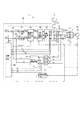
本発明の第1実施形態による回転電機制御装置を図1に示す。回転電機制御装置1は、回転電機としてのモータ10を駆動制御するものである。回転電機制御装置1は、モータ10とともに、例えば車両のステアリング操作をアシストするための電動パワーステアリング装置に採用される。
A rotating electrical machine control apparatus according to a first embodiment of the present invention is shown in FIG. The rotating electrical
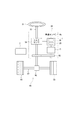
図2は、電動パワーステアリング装置99を備えたステアリングシステム90の全体構成を示すものである。電動パワーステアリング装置99には、ハンドル91に接続されたステアリングシャフト92にトルクセンサ94が設けられている。トルクセンサ94は、運転者からハンドル91を経由してステアリングシャフト92に入力される操舵トルクを検出する。
FIG. 2 shows an overall configuration of a
ステアリングシャフト92の先端にはピニオンギア96が設けられており、ピニオンギア96はラック軸97に噛み合っている。ラック軸97の両端には、タイロッド等を介して一対の車輪98が回転可能に連結されている。
これにより、運転者がハンドル91を回転させると、ハンドル91に接続されたステアリングシャフト92が回転し、ステアリングシャフト92の回転運動は、ピニオンギア96によってラック軸97の直線運動に変換され、ラック軸97の直線運動変位に応じた角度について一対の車輪98が操舵される。
A
As a result, when the driver rotates the
電動パワーステアリング装置99は、操舵アシストトルクを発生するモータ10、当該モータ10を駆動制御する回転電機制御装置1、モータ10の回転を減速してステアリングシャフト92に伝える減速ギア93等を備える。モータ10は、減速ギア93を正逆回転させる。電動パワーステアリング装置99は、上述のトルクセンサ94、および、車速を検出する車速センサ95を含む。
この構成により、電動パワーステアリング装置99は、ハンドル91の操舵を補助するための操舵アシストトルクをモータ10から発生し、ステアリングシャフト92に伝達する。
The electric
With this configuration, the electric
モータ10は、三相ブラシレスモータであり、電源としてのバッテリ2の電力により駆動する。モータ10は、図示しないロータおよびステータを有している。ロータは、円板状の部材であり、その表面または内部に永久磁石が貼り付けられ、磁極を有している。ロータは、ステータの内側に収容されるとともに、回転可能に支持されている。ステータは、径内方向へ所定角度毎に突出する突出部を有し、この突出部に図1に示す巻線としてのコイル11、コイル12およびコイル13が巻回されている。コイル11、コイル12およびコイル13は、それぞれ、モータ10のU相、V相およびW相に対応している。また、モータ10には、ロータの回転位置θを検出する位置センサ14が設けられている。
The
回転電機制御装置1は、図1に示すように、インバータ部20、電源電圧検出手段としての電圧センサ3、モータ電流検出手段としての電流センサ4、5、6、および、制御部30等を備えている。
インバータ部20は、3相インバータであり、6つのスイッチング素子21を有している。本実施形態では、スイッチング素子21は、電界効果トランジスタの一種であるMOSFET(metal-oxide-semiconductor field-effect transistor)である。2つのスイッチング素子21は、1つのスイッチング素子対(アーム)を構成している。3つのスイッチング素子対は、それぞれ、モータ10のコイル11、コイル12およびコイル13に接続されている。また、3つのスイッチング素子対には、バッテリ2が接続されている。インバータ部20は、後述する制御部30によりスイッチング素子21の作動が制御され、バッテリ2からの電力を変換しモータ10に供給する。
As shown in FIG. 1, the rotating electrical
The
電圧センサ3は、バッテリ2とインバータ部20との間に設けられ、バッテリ2からインバータ部20に印加される電圧である電源電圧Vinを検出可能である。
電流センサ4、5、6は、本実施形態では、例えばシャント抵抗であり、それぞれ、スイッチング素子対とコイル11との間、スイッチング素子対とコイル12との間、スイッチング素子対とコイル13との間に設けられている。インバータ部20からモータ10に電流が流れるとき、電流センサ4、5、6には、それぞれ、コイル11に流れる電流であるU相電流Iu、コイル12に流れる電流であるV相電流Iv、コイル13に流れる電流であるW相電流Iwが流れる。これにより、電流センサ4、5、6は、それぞれ、モータ電流としてのU相電流Iu、V相電流Iv、W相電流Iwを検出可能である。
The
In the present embodiment, the
制御部30は、回転電機制御装置1全体の制御を司るものであって、図示しないマイクロコンピュータ、レジスタ、駆動回路等で構成される。
制御部30は、物理的な構成部位としてA/D変換器7、8、9を有し、ソフトウェア的な構成部位として回転角速度算出部31、3相/2相座標変換部32、減算器41、42、PI制御部43、44、制限後電圧指令値算出部45、2相/3相座標変換部46、PWM制御器47、制限ゲイン決定部50を有している。
The
The
A/D変換器7、8、9には、それぞれ、電流センサ4、5、6からの出力値、すなわち、U相電流Iu、V相電流Iv、W相電流Iwのアナログ値が入力される。A/D変換器7、8、9は、それぞれ、U相電流Iu、V相電流Iv、W相電流Iwのアナログ値をデジタル値に変換し出力する。
回転角速度算出部31は、位置センサ14により検出した回転位置θに基づき、モータ10の回転角速度ωを算出する。
A /
The rotational angular
制御部30は、回転角速度算出部31により算出したモータ10の回転角速度ω、トルクセンサ94により検出した操舵トルク、および、車速センサ95により検出した車速に基づき、q軸電流指令値Iq*およびd軸電流指令値Id*を算出する。
3相/2相座標変換部32は、A/D変換器7、8、9によりデジタル値に変換されたU相電流Iu、V相電流Iv、W相電流Iwを、位置センサ14により検出した回転位置θに基づき、3相交流座標からd−q座標のq軸電流検出値Iqおよびd軸電流検出値Idに変換する。
Based on the rotational angular velocity ω of the
The three-phase / two-phase coordinate
減算器41は、入力されたq軸電流指令値Iq*とq軸電流検出値Iqとの差分であるq軸電流偏差ΔIqをPI制御部43に出力する。減算器42は、入力されたd軸電流指令値Id*とd軸電流検出値Idとの差分であるd軸電流偏差ΔIdをPI制御部44に出力する。
The
PI制御部43は、減算器41から入力されたq軸電流偏差ΔIqに基づき、q軸電流指令値Iq*に、実電流であるq軸電流検出値Iqを追従させるためのフィードバック制御を行う。具体的には、PI制御部43は、q軸電流偏差ΔIqに所定のPIゲインを乗ずることにより、モータ10を駆動するためにインバータ部20からモータ10に印加すべきq軸電圧の指令値であるq軸電圧指令値Vq*を算出し、制限後電圧指令値算出部45に出力する。
Based on the q-axis current deviation ΔIq input from the
PI制御部44は、減算器42から入力されたd軸電流偏差ΔIdに基づき、d軸電流指令値Id*に、実電流であるd軸電流検出値Idを追従させるためのフィードバック制御を行う。具体的には、PI制御部44は、d軸電流偏差ΔIdに所定のPIゲインを乗ずることにより、モータ10を駆動するためにインバータ部20からモータ10に印加すべきd軸電圧の指令値であるd軸電圧指令値Vd*を算出し、制限後電圧指令値算出部45に出力する。
ここで、減算器41、42、PI制御部43、44は、特許請求の範囲における「電圧指令値算出手段」に対応している。
Based on the d-axis current deviation ΔId input from the
Here, the
制限後電圧指令値算出部45は、PI制御部43から入力されたq軸電圧指令値Vq*、および、後述する制限ゲインGlimitに基づき、制限後のq軸電圧指令値である制限後q軸電圧指令値Vq**を算出し、2相/3相座標変換部46に出力する。具体的には、q軸電圧指令値Vq*に制限ゲインGlimitを乗ずることにより制限後q軸電圧指令値Vq**を算出する。すなわち、Vq**は、下記式(1)により算出される。
Vq**=Vq*×Glimit ・・・式(1)
The post-limit voltage command
Vq ** = Vq ** × Glimit Expression (1)
また、制限後電圧指令値算出部45は、PI制御部44から入力されたd軸電圧指令値Vd*、および、制限ゲインGlimitに基づき、制限後のd軸電圧指令値である制限後d軸電圧指令値Vd**を算出し、2相/3相座標変換部46に出力する。具体的には、d軸電圧指令値Vd*に制限ゲインGlimitを乗ずることにより制限後d軸電圧指令値Vd**を算出する。すなわち、Vd**は、下記式(2)により算出される。
Vd**=Vd*×Glimit ・・・式(2)
ここで、制限後電圧指令値算出部45は、特許請求の範囲における「制限後電圧指令値算出手段」に対応している。
Further, the post-restriction voltage command
Vd ** = Vd ** × Glimit Expression (2)
Here, the post-restriction voltage command
2相/3相座標変換部46は、制限後電圧指令値算出部45から入力された制限後q軸電圧指令値Vq**および制限後d軸電圧指令値Vd**を、位置センサ14により検出した回転位置θに基づき、3相の電圧指令値であるU相電圧指令値Vu*、V相電圧指令値Vv*、W相電圧指令値Vw*に変換し、PWM制御器47に出力する。
The two-phase / three-phase coordinate
PWM制御器47は、2相/3相座標変換部46から入力されたU相電圧指令値Vu*、V相電圧指令値Vv*、W相電圧指令値Vw*に基づき、各相のスイッチング素子21のオン期間のデューティ比に対応するU相デューティ指令値Du、V相デューティ指令値Dv、W相デューティ指令値Dwを算出し、インバータ部20に出力する。
ここで、PWM制御器47は、特許請求の範囲における「デューティ指令値算出手段」として機能する。
The
Here, the
インバータ部20は、PWM制御器47から入力されたU相デューティ指令値Du、V相デューティ指令値Dv、W相デューティ指令値Dwに基づき、各相のスイッチング素子21をオンオフ制御することにより、U相デューティ指令値Du、V相デューティ指令値Dv、W相デューティ指令値Dwに対応する電圧をコイル11、コイル12、コイル13に印加する。これにより、バッテリ2からインバータ部20を経由してモータ10に電流(モータ電流)が流れる。その結果、モータ10が回転し、モータ10から操舵アシストトルクが出力される。
このように、PWM制御器47は、インバータ部20を経由してモータ10をPWM(パルス幅変調)制御する。
The
Thus, the
次に、制限ゲイン決定部50による制限ゲインGlimitの決定の仕方について説明する。
制限ゲイン決定部50は、以下の一連のステップ1〜4を経ることにより制限ゲインGlimitを決定する。なお、制限ゲイン決定部50は、一連のステップ1〜4を所定の周期で繰り返し実行し、都度、制限ゲインGlimitを決定する。
Next, how the limit
The limit
(ステップ1)
制限ゲイン決定部50は、電流センサ4、5、6により検出したU相電流Iu、V相電流Iv、W相電流Iw(A/D変換器7、8、9によりデジタル値に変換したU相電流Iu、V相電流Iv、W相電流Iw)に基づき、インバータ部20からモータ10に供給される電力であるインバータ電力Pinvを推定する。より具体的には、制限ゲイン決定部50は、電圧センサ3により検出した電源電圧Vin、PWM制御器47により算出したU相デューティ指令値Du、V相デューティ指令値Dv、W相デューティ指令値Dw、および、A/D変換器7、8、9によりデジタル値に変換したU相電流Iu、V相電流Iv、W相電流Iwに基づき、インバータ電力Pinvを推定する。制限ゲイン決定部50は、下記式(3)によりインバータ電力Pinvを推定(算出)する。
Pinv=Vin×(Du/100)×Iu+Vin×(Dv/100)×Iv+Vin×(Dw/100)×Iw ・・・式(3)
ここで、制限ゲイン決定部50は、特許請求の範囲における「インバータ電力推定手段」として機能する。
(Step 1)
The limiting
Pinv = Vin × (Du / 100) × Iu + Vin × (Dv / 100) × Iv + Vin × (Dw / 100) × Iw Expression (3)
Here, the limit
(ステップ2)
制限ゲイン決定部50は、ステップ1で推定したインバータ電力Pinv、および、電圧センサ3により検出した電源電圧Vinに基づき、バッテリ2からインバータ部20に流れる電流である電源電流Iinを推定する。制限ゲイン決定部50は、下記式(4)により電源電流Iinを推定(算出)する。
Iin=Pinv/Vin ・・・式(4)
ここで、制限ゲイン決定部50は、特許請求の範囲における「電源電流推定手段」として機能する。
(Step 2)
Based on the inverter power Pinv estimated in
Iin = Pinv / Vin (4)
Here, the limiting
(ステップ3)
制限ゲイン決定部50は、電源電流Iinの目標値である目標電源電流Iin*を決定する。本実施形態では、制限ゲイン決定部50は、目標電源電流Iin*を任意の所定値(A)に決定(設定)する。ここで、制限ゲイン決定部50は、特許請求の範囲における「目標電源電流決定手段」として機能する。
(Step 3)
Limiting
(ステップ4)
制限ゲイン決定部50は、ステップ2で推定した電源電流Iin、および、ステップ3で決定した目標電源電流Iin*に基づき、制限ゲインGlimitを決定する。より具体的には、制限ゲイン決定部50は、前回のステップ4で決定した制限ゲインGlimit(n−1)、電源電流Iin、および、目標電源電流Iin*に基づき、制限ゲインGlimitを決定する。制限ゲイン決定部50は、下記式(5)により制限ゲインGlimitを決定(算出)する。
Glimit(n)=Glimit(n−1)×Iin*/Iin ・・・式(5)
式(5)において、Glimit(n)は今回値、Glimit(n−1)は前回値を表す。ここで、制限ゲイン決定部50は、特許請求の範囲における「制限ゲイン決定手段」として機能する。また、Glimit(n)は、最大で1となる様にガード処置を行う。
(Step 4)
Limiting
Glimit (n) = Glimit (n−1) × Iin * / Iin (5)
In Equation (5), Glimit (n) represents the current value, and Glimit (n−1) represents the previous value. Here, the limit
以上が、制限ゲイン決定部50による制限ゲインGlimitの決定の仕方である。制限ゲイン決定部50は、ステップ1〜4を実行することにより制限ゲインGlimitを決定すると、決定した制限ゲインGlimitを制限後電圧指令値算出部45に出力する。
制限後電圧指令値算出部45は、上述のように、入力されたq軸電圧指令値Vq*、d軸電圧指令値Vd*および制限ゲインGlimitに基づき、制限後q軸電圧指令値Vq**および制限後d軸電圧指令値Vd**を算出し、2相/3相座標変換部46に出力する。
The above is how the limit
As described above, the post-limit voltage command
2相/3相座標変換部46は、入力された制限後q軸電圧指令値Vq**および制限後d軸電圧指令値Vd**をU相電圧指令値Vu*、V相電圧指令値Vv*、W相電圧指令値Vw*に変換し、PWM制御器47に出力する。
PWM制御器47は、入力されたU相電圧指令値Vu*、V相電圧指令値Vv*、W相電圧指令値Vw*に基づき、U相デューティ指令値Du、V相デューティ指令値Dv、W相デューティ指令値Dwを算出し、インバータ部20に出力する。
The 2-phase / 3-phase coordinate
The
インバータ部20は、入力されたU相デューティ指令値Du、V相デューティ指令値Dv、W相デューティ指令値Dwに基づき、U相デューティ指令値Du、V相デューティ指令値Dv、W相デューティ指令値Dwに対応する電圧をコイル11、コイル12、コイル13に印加する。これにより、バッテリ2からインバータ部20を経由してモータ10に電流(モータ電流)が流れる。このときバッテリ2からインバータ部20に流れる電源電流Iinは、制限ゲインGlimit(制限後q軸電圧指令値Vq**および制限後d軸電圧指令値Vd**)に基づき、制限されている。これにより、給電経路上の発熱やインバータ部20のスイッチング素子21の破壊を抑制することができる。ここで、2相/3相座標変換部46およびPWM制御器47は、特許請求の範囲における「電流制限手段」として機能する。
Based on the input U-phase duty command value Du, V-phase duty command value Dv, and W-phase duty command value Dw, the
以上説明したように、本実施形態では、電源電流Iinを制限するための制限ゲインGlimitを決定するにあたりトルク定数(Kt)やモータ抵抗(R)等、モータ10毎あるいは環境温度等によりばらつきのある値を必要とせず、電源電圧Vinやモータ電流Iu、Iv、Iwの検出値、および、制御部30で推定、決定または算出した値に基づき制限ゲインGlimitを決定する。これにより、モータ10の個体差および環境温度等の制限ゲインGlimitへの影響を無くすことができる。その結果、電源電流Iinの過剰な制限によってモータ10に出力不足が生じる、または、電源電流Iinの制限不足によって過大な電源電流Iinが流れるといった問題を解決することができる。したがって、本実施形態では、電源電流Iinを安定して制限しつつモータ10の駆動を制御することができる。
As described above, in the present embodiment, when determining the limiting gain Glimit for limiting the power supply current Iin, there are variations depending on the
また、本実施形態では、モータ10は、複数の相(U相、V相、W相)に対応するコイル11、コイル12、コイル13を有している。インバータ部20は、コイル11、コイル12、コイル13に対応するスイッチング素子21を有している。制御部30は、「デューティ指令値算出手段」として機能することにより、各相のスイッチング素子21のオン期間のデューティ比に対応するデューティ指令値Du、Dv、Dwを算出する。そして、制御部30は、「インバータ電力推定手段」として機能することにより、電圧センサ3により検出した電源電圧Vin、算出した各相のデューティ指令値Du、Dv、Dw、および、電流センサ4、5、6により検出したモータ電流Iu、Iv、Iwに基づき、インバータ電力Pinvを推定する。これは、インバータ電力Pinvの推定の仕方の一例を示すものである。
In the present embodiment, the
また、本実施形態では、制御部30は、「制限後電圧指令値算出手段」として機能することにより、q軸電圧指令値Vq*およびd軸電圧指令値Vd*のそれぞれについて制限後q軸電圧指令値Vq**および制限後d軸電圧指令値Vd**を算出する。これにより、電源電流Iinのうちq軸成分およびd軸成分の両方を制限することができる。
Further, in the present embodiment, the
また、本実施形態では、制御部30は、「インバータ電力推定手段」、「電源電流推定手段」、「目標電源電流決定手段」、「制限ゲイン決定手段」、「制限後電圧指令値算出手段」、「電流制限手段」としての処理を所定の周期で繰り返し実行することにより、バッテリ2からインバータ部20に流れる電源電流Iinを所定の周期で制限する。電動パワーステアリング装置99では、運転者のハンドル91の操作によってはモータ10に大電流が急激に流れる場合がある。本実施形態による回転電機制御装置1では、比較的短い周期で制限ゲインGlimitを決定し電源電流Iinを制限するため、インバータ部20に流れる電源電流Iinを制限しつつ電動パワーステアリング装置99のモータ10の駆動を制御するのに好適である。
Further, in the present embodiment, the
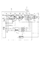
(第2実施形態)
本発明の第2実施形態による回転電機制御装置を図3に示す。第2実施形態は、物理的な構成は第1実施形態と同様であるものの、制限ゲインGlimitの決定の仕方等が第1実施形態と異なる。
(Second Embodiment)
A rotating electrical machine control apparatus according to a second embodiment of the present invention is shown in FIG. The second embodiment is similar in physical configuration to the first embodiment, but differs from the first embodiment in how to determine the limiting gain Glimit.
第2実施形態では、制限ゲイン決定部50は、以下の一連のステップ1〜4を経ることにより制限ゲインGlimitを決定する。なお、本実施形態においても、制限ゲイン決定部50は、一連のステップ1〜4を所定の周期で繰り返し実行し、都度、制限ゲインGlimitを決定する。
In the second embodiment, the limit
(ステップ1)
制限ゲイン決定部50は、電流センサ4、5、6により検出したU相電流Iu、V相電流Iv、W相電流Iw(A/D変換器7、8、9によりデジタル値に変換したU相電流Iu、V相電流Iv、W相電流Iw)に基づき、インバータ部20からモータ10に供給される電力であるインバータ電力Pinvを推定する。より具体的には、制限ゲイン決定部50は、PI制御部43およびPI制御部44により算出されたq軸電圧指令値Vq*およびd軸電圧指令値Vd*、ならびに、3相/2相座標変換部32によりU相電流Iu、V相電流Iv、W相電流Iwから変換されたq軸電流検出値Iqおよびd軸電流検出値Idに基づき、インバータ電力Pinvを推定する。制限ゲイン決定部50は、下記式(6)によりインバータ電力Pinvを推定(算出)する。
Pinv=Vq*×Iq+Vd*×Id ・・・式(6)
ここで、制限ゲイン決定部50は、特許請求の範囲における「インバータ電力推定手段」として機能する。
(Step 1)
The limiting
Pinv = Vq * × Iq + Vd * × Id (6)
Here, the limit
(ステップ2)
制限ゲイン決定部50は、ステップ1で推定したインバータ電力Pinv、および、電圧センサ3により検出した電源電圧Vinに基づき、バッテリ2からインバータ部20に流れる電流である電源電流Iinを推定する。制限ゲイン決定部50は、下記式(7)により電源電流Iinを推定(算出)する。
Iin=Pinv/Vin ・・・式(7)
ここで、制限ゲイン決定部50は、特許請求の範囲における「電源電流推定手段」として機能する。
(Step 2)
Based on the inverter power Pinv estimated in
Iin = Pinv / Vin (7)
Here, the limiting
(ステップ3)
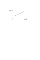
制限ゲイン決定部50は、電源電流Iinの目標値である目標電源電流Iin*を決定する。本実施形態では、制限ゲイン決定部50は、例えば図4に示すマップMに基づき目標電源電流Iin*を決定する。ここで、マップMは電源電圧Vinと目標電源電流Iin*との対応を示すものであり、電源電圧Vin(V)が大きくなるほど目標電源電流Iin*(A)も大きな値が決定(設定)される。ここで、制限ゲイン決定部50は、特許請求の範囲における「目標電源電流決定手段」として機能する。
(Step 3)
Limiting
(ステップ4)
制限ゲイン決定部50は、ステップ2で推定した電源電流Iin、および、ステップ3で決定した目標電源電流Iin*に基づき、制限ゲインGlimitを決定する。より具体的には、制限ゲイン決定部50は、前回のステップ4で決定した制限ゲインGlimit(n−1)、電源電流Iin、および、目標電源電流Iin*に基づき算出した値を、ローパスフィルタ(LPF)を通過させることにより制限ゲインGlimitを決定する。制限ゲイン決定部50は、下記式(8)により制限ゲインGlimitを決定(算出)する。
Glimit(n)=LPF(Glimit(n−1)×Iin*/Iin) ・・・式(8)
また、Glimit(n)は、最大で1となる様にガード処置を行う。ここで、制限ゲイン決定部50は、特許請求の範囲における「制限ゲイン決定手段」として機能する。
(Step 4)
Limiting
Glimit (n) = LPF (Glimit (n−1) × Iin * / Iin) (8)
Further, the guard treatment is performed so that Glimit (n) becomes 1 at the maximum. Here, the limit
以上が、第2実施形態の制限ゲイン決定部50による制限ゲインGlimitの決定の仕方である。制限ゲイン決定部50は、ステップ1〜4を実行することにより制限ゲインGlimitを決定すると、決定した制限ゲインGlimitを制限後電圧指令値算出部45に出力する。
The above is how to determine the limiting gain Glimit by the limiting
制限後電圧指令値算出部45は、入力されたq軸電圧指令値Vq*、d軸電圧指令値Vd*および制限ゲインGlimitに基づき、制限後q軸電圧指令値Vq**および制限後d軸電圧指令値Vd**を算出し、2相/3相座標変換部46に出力する。ここで、本実施形態では、制限後電圧指令値算出部45は、下記式(9)、式(10)によりVq**およびVd**を算出する。
Vq**=Vq* ・・・式(9)
Vd**=Vd*×Glimit ・・・式(10)
The post-restriction voltage command
Vq ** = Vq * (9)
Vd ** = Vd ** × Glimit Expression (10)
このように、本実施形態では、q軸電圧指令値Vq*をそのまま制限後q軸電圧指令値Vq**とし、d軸電圧指令値Vd*に制限ゲインGlimitを乗じたものを制限後d軸電圧指令値Vd**とする。すなわち、d軸電圧についてのみ制限後の電圧指令値(制限後d軸電圧指令値Vd**)を算出する。これにより、電源電流Iinのうちd軸成分のみが制限される。 Thus, in this embodiment, the q-axis voltage command value Vq * is directly used as the restricted q-axis voltage command value Vq **, and the d-axis voltage command value Vd * multiplied by the restriction gain Glimit is used as the d-axis after restriction. The voltage command value is Vd **. That is, a voltage command value after restriction (after d-axis voltage command value Vd **) is calculated only for the d-axis voltage. As a result, only the d-axis component of the power supply current Iin is limited.
以上説明したように、本実施形態では、電源電流Iinを制限するための制限ゲインGlimitを決定するにあたりトルク定数(Kt)やモータ抵抗(R)等、モータ10毎あるいは環境温度等によりばらつきのある値を必要とせず、電源電圧Vinやモータ電流Iu、Iv、Iwの検出値、および、制御部30で推定、決定または算出した値に基づき制限ゲインGlimitを決定する。これにより、モータ10の個体差および環境温度等の制限ゲインGlimitへの影響を無くすことができる。したがって、本実施形態では、第1実施形態と同様、電源電流Iinを安定して制限しつつモータ10の駆動を制御することができる。
As described above, in the present embodiment, when determining the limiting gain Glimit for limiting the power supply current Iin, there are variations depending on the
また、本実施形態では、制御部30は、「インバータ電力推定手段」として機能することにより、算出したq軸電圧指令値Vq*およびd軸電圧指令値Vd*、ならびに、電流センサ4、5、6により検出したモータ電流Iu、Iv、Iw(q軸電流検出値Iqおよびd軸電流検出値Id)に基づき、インバータ電力Pinvを推定する。これは、インバータ電力Pinvの推定の仕方の一例を示すものである。
In the present embodiment, the
また、本実施形態では、制御部30は、「目標電源電流決定手段」として機能することにより、電源電圧Vinと目標電源電流Iin*との対応を示すマップMに基づき、目標電源電流Iin*を決定する。本実施形態では、マップMに基づき、電源電圧Vin(V)が大きくなるほど目標電源電流Iin*(A)も大きな値が決定(設定)される。これにより、電源電圧Vinが大きいときほど電源電流Iinの制限を緩くするというように、電源電圧Vinに応じて電源電流Iinの制限の程度を変更することができる。
Further, in the present embodiment, the
また、本実施形態では、制御部30は、「制限ゲイン決定手段」として機能するとき、入力信号の所定の帯域を制限するフィルタであるローパスフィルタを通過した値を制限ゲインGlimitとして決定する。これにより、電源電流Iinを制限する際のハンチングを抑制することができる。
In the present embodiment, when the
また、本実施形態では、制御部30は、「制限後電圧指令値算出手段」として機能することにより、d軸電圧指令値Vd*について制限後d軸電圧指令値Vd**を算出する。これにより、電源電流Iinのうちd軸成分のみが制限される。よって、本実施形態は、モータ10の回転に寄与するd軸電流を制限するため、モータ10のトルクを重視する場合に好適である。
In the present embodiment, the
(他の実施形態)
本発明の他の実施形態では、阻害要因がない限り、上述の実施形態の一部の構成同士を組み合わせてもよい。例えば第1実施形態において、マップに基づき目標電源電流を決定したり、フィルタを通過した値を制限ゲインとして決定したりといった具合である。
(Other embodiments)
In other embodiment of this invention, as long as there is no obstruction factor, you may combine the one part structures of the above-mentioned embodiment. For example, in the first embodiment, a target power supply current is determined based on a map, or a value that has passed through a filter is determined as a limiting gain.
また、本発明の他の実施形態では、マップに限らず、計算式に基づき目標電源電流を決定することとしてもよい。
また、本発明の他の実施形態では、q軸電圧指令値についてのみ制限後の電圧指令値(制限後q軸電流指令値)を算出することとしてもよい。この場合、電源電流のうちq軸成分のみが制限される。よって、この実施形態は、回転電機のトルクに寄与するq軸電流を制限するため、回転電機の回転を重視する場合に好適である。
In another embodiment of the present invention, the target power supply current may be determined based on a calculation formula without being limited to the map.
In another embodiment of the present invention, a restricted voltage command value (a restricted q-axis current command value) may be calculated only for the q-axis voltage command value. In this case, only the q-axis component of the power supply current is limited. Therefore, this embodiment is suitable when importance is placed on the rotation of the rotating electrical machine because the q-axis current that contributes to the torque of the rotating electrical machine is limited.
また、本発明の他の実施形態では、回転電機は、3相以外の多相回転電機であってもよい。
本発明による回転電機制御装置は、電動パワーステアリング装置の回転電機に限らず、他の装置等に用いられる回転電機の制御装置として適用することができる。
このように、本発明は、上記実施形態に限定されるものではなく、その要旨を逸脱しない範囲で種々の形態で実施可能である。
In another embodiment of the present invention, the rotating electrical machine may be a multi-phase rotating electrical machine other than three-phase.
The rotating electrical machine control device according to the present invention is not limited to the rotating electrical machine of the electric power steering device, and can be applied as a control device for a rotating electrical machine used for other devices.
Thus, the present invention is not limited to the above-described embodiment, and can be implemented in various forms without departing from the gist thereof.
1 ・・・回転電機制御装置
2 ・・・バッテリ(電源)
3 ・・・電圧センサ(電源電圧検出手段)
4、5、6 ・・・電流センサ(モータ電流検出手段)
10 ・・・モータ(回転電機)
20 ・・・インバータ部
30 ・・・制御部
41、42 ・・・減算器(電圧指令値算出手段)
43、44 ・・・PI制御部(電圧指令値算出手段)
45 ・・・制限後電圧指令値算出部(制限後電圧指令値算出手段)
46 ・・・2相/3相座標変換部(電流制限手段)
47 ・・・PWM制御器(電流制限手段)
50 ・・・制限ゲイン決定部(インバータ電力推定手段、電源電流推定手段、目標電源電流決定手段、制限ゲイン決定手段)
DESCRIPTION OF
3 ... Voltage sensor (power supply voltage detection means)
4, 5, 6 ... current sensor (motor current detection means)
10 ... Motor (rotary electric machine)
20 ...
43, 44 ... PI controller (voltage command value calculation means)
45 ... Voltage command value calculation unit after limitation (voltage command value calculation means after limitation)
46 ... 2-phase / 3-phase coordinate converter (current limiting means)
47 ・ ・ ・ PWM controller (current limiting means)
50: Limit gain determining unit (inverter power estimating means, power supply current estimating means, target power supply current determining means, limit gain determining means)
Claims (8)
前記電源からの電力を変換し前記回転電機に供給するインバータ部(20)と、
前記電源から前記インバータ部に印加される電圧である電源電圧を検出する電源電圧検出手段(3)と、
前記インバータ部から前記回転電機に流れる電流であるモータ電流を検出するモータ電流検出手段(4、5、6)と、
前記インバータ部の作動を制御することにより前記回転電機の駆動を制御する制御部(30)と、を備え、
前記制御部は、
前記回転電機を駆動するために前記インバータ部から前記回転電機に流すべき電流の指令値である電流指令値、および、前記モータ電流検出手段により検出した前記モータ電流に基づき、前記回転電機を駆動するために前記インバータ部から前記回転電機に印加すべき電圧の指令値である電圧指令値を算出する電圧指令値算出手段(41、42、43、44)、
前記モータ電流検出手段により検出した前記モータ電流に基づき、前記インバータ部から前記回転電機に供給される電力であるインバータ電力を推定するインバータ電力推定手段(50)、
前記インバータ電力推定手段により推定した前記インバータ電力、および、前記電源電圧検出手段により検出した前記電源電圧に基づき、前記電源から前記インバータ部に流れる電流である電源電流を推定する電源電流推定手段(50)、
前記電源電流の目標値である目標電源電流を決定する目標電源電流決定手段(50)、
制限ゲインを決定する制限ゲイン決定手段(50)、
前記電圧指令値算出手段により算出した前記電圧指令値、および、前記制限ゲイン決定手段により決定した前記制限ゲインに基づき、制限後の前記電圧指令値である制限後電圧指令値を算出する制限後電圧指令値算出手段(45)、および、
前記制限後電圧指令値算出手段により算出した前記制限後電圧指令値に対応する指令値を前記インバータ部に出力することにより前記電源電流を制限可能な電流制限手段(46、47)を有し、
前記制限ゲイン決定手段は、前記電源電流推定手段により推定した前記電源電流、前記目標電源電流決定手段により決定した前記目標電源電流、および、前回決定された制限ゲインに基づき、今回の制限ゲインを決定することを特徴とする回転電機制御装置。 A rotating electrical machine control device (1) for controlling a rotating electrical machine (10) driven by electric power from a power source (2),
An inverter unit (20) for converting electric power from the power source and supplying the electric power to the rotating electrical machine;
Power supply voltage detection means (3) for detecting a power supply voltage that is a voltage applied to the inverter unit from the power supply;
Motor current detection means (4, 5, 6) for detecting a motor current which is a current flowing from the inverter unit to the rotating electrical machine;
A control unit (30) for controlling the drive of the rotating electrical machine by controlling the operation of the inverter unit,
The controller is
The rotating electrical machine is driven based on a current command value that is a command value of a current that should be passed from the inverter unit to the rotating electrical machine to drive the rotating electrical machine, and the motor current detected by the motor current detecting means. Voltage command value calculating means (41, 42, 43, 44) for calculating a voltage command value that is a command value of a voltage to be applied from the inverter unit to the rotating electrical machine,
Inverter power estimation means (50) for estimating inverter power, which is power supplied from the inverter unit to the rotating electrical machine, based on the motor current detected by the motor current detection means;
Based on the inverter power estimated by the inverter power estimating means and the power supply voltage detected by the power supply voltage detecting means, a power supply current estimating means (50) for estimating a power supply current flowing from the power supply to the inverter unit. ),
Target power source current determining means (50) for determining a target power source current which is a target value of the power source current;
Limiting gain determining means for determining a limit gain (50),
Based on the voltage command value calculated by the voltage command value calculation means and the limit gain determined by the limit gain determination means, a post-restriction voltage that calculates a post-restriction voltage command value that is the voltage command value after restriction Command value calculation means (45), and
Possess the limiting current limiting means supply current (46, 47) by outputting a command value corresponding to the restriction after the voltage command value calculated by the post-restriction voltage command value calculating means to the inverter section,
The limit gain determining means determines a current limit gain based on the power supply current estimated by the power supply current estimating means, the target power supply current determined by the target power supply current determining means, and the previously determined limit gain. A rotating electrical machine control device.
前記インバータ部は、前記巻線の各相に対応するスイッチング素子(21)を有し、
前記制御部は、各相の前記スイッチング素子のオン期間のデューティ比に対応するデューティ指令値を算出するデューティ指令値算出手段(47)を有し、
前記インバータ電力推定手段は、前記電源電圧検出手段により検出した前記電源電圧、前記デューティ指令値算出手段により算出した各相の前記デューティ指令値、および、前記モータ電流検出手段により検出した前記モータ電流に基づき、前記インバータ電力を推定することを特徴とする請求項1に記載の回転電機制御装置。 The rotating electrical machine has windings (11, 12, 13) corresponding to a plurality of phases,
The inverter unit includes a switching element (21) corresponding to each phase of the winding,
The control unit includes duty command value calculation means (47) for calculating a duty command value corresponding to a duty ratio of an ON period of the switching element of each phase,
The inverter power estimation means is configured to calculate the power supply voltage detected by the power supply voltage detection means, the duty command value of each phase calculated by the duty command value calculation means, and the motor current detected by the motor current detection means. The rotating electrical machine control device according to claim 1, wherein the inverter power is estimated based on the inverter power.
運転者の操舵を補助するためのアシストトルクを発生する前記回転電機と、
を備える電動パワーステアリング装置(99)。 The rotating electrical machine control device according to any one of claims 1 to 7,
The rotating electrical machine that generates an assist torque for assisting a driver's steering;
An electric power steering device (99) comprising:
Priority Applications (4)
| Application Number | Priority Date | Filing Date | Title |
|---|---|---|---|
| JP2013050422A JP5811363B2 (en) | 2013-03-13 | 2013-03-13 | Rotating electrical machine control device and electric power steering device using the same |
| US14/182,309 US9407177B2 (en) | 2013-03-13 | 2014-02-18 | Rotating electric machine control device and electric power steering apparatus |
| DE102014103064.8A DE102014103064B4 (en) | 2013-03-13 | 2014-03-07 | Rotating electric machine control device and electric power steering device |
| CN201410089678.1A CN104052344B (en) | 2013-03-13 | 2014-03-12 | Rotary electric machine controller and electric power steering apparatus |
Applications Claiming Priority (1)
| Application Number | Priority Date | Filing Date | Title |
|---|---|---|---|
| JP2013050422A JP5811363B2 (en) | 2013-03-13 | 2013-03-13 | Rotating electrical machine control device and electric power steering device using the same |
Publications (2)
| Publication Number | Publication Date |
|---|---|
| JP2014180070A JP2014180070A (en) | 2014-09-25 |
| JP5811363B2 true JP5811363B2 (en) | 2015-11-11 |
Family
ID=51419077
Family Applications (1)
| Application Number | Title | Priority Date | Filing Date |
|---|---|---|---|
| JP2013050422A Expired - Fee Related JP5811363B2 (en) | 2013-03-13 | 2013-03-13 | Rotating electrical machine control device and electric power steering device using the same |
Country Status (4)
| Country | Link |
|---|---|
| US (1) | US9407177B2 (en) |
| JP (1) | JP5811363B2 (en) |
| CN (1) | CN104052344B (en) |
| DE (1) | DE102014103064B4 (en) |
Cited By (1)
| Publication number | Priority date | Publication date | Assignee | Title |
|---|---|---|---|---|
| US11088532B2 (en) | 2019-04-02 | 2021-08-10 | Denso Corporation | Control device |
Families Citing this family (13)
| Publication number | Priority date | Publication date | Assignee | Title |
|---|---|---|---|---|
| GB201308249D0 (en) * | 2013-05-08 | 2013-06-12 | Trw Ltd | Method of controlling a motor of an electric power assisted steering system |
| JP6260502B2 (en) * | 2014-09-16 | 2018-01-17 | 株式会社デンソー | Motor control device |
| JP6428248B2 (en) * | 2014-12-22 | 2018-11-28 | 株式会社デンソー | Motor control device |
| JP6436005B2 (en) * | 2015-07-02 | 2018-12-12 | 株式会社デンソー | Rotating electrical machine control device |
| JP6376067B2 (en) * | 2015-07-27 | 2018-08-22 | 株式会社デンソー | Control device and electric power steering device using the same |
| US9634603B2 (en) * | 2015-08-24 | 2017-04-25 | Hamilton Sundstrand Corporation | Power limiting for motor current controllers |
| DE102016202410A1 (en) * | 2016-02-17 | 2017-08-17 | Zf Friedrichshafen Ag | Method and arrangement for monitoring a PSM machine |
| US10843793B2 (en) | 2017-05-31 | 2020-11-24 | Simmonds Precision Products, Inc. | Electronic braking arrangements |
| US10330070B2 (en) * | 2017-11-14 | 2019-06-25 | Gm Global Technology Operations Llc. | Method and apparatus for operating a starter for an internal combustion engine |
| JP7047686B2 (en) * | 2018-09-18 | 2022-04-05 | 株式会社デンソー | Motor drive and steering system |
| WO2020079899A1 (en) * | 2018-10-19 | 2020-04-23 | 日本精工株式会社 | Motor control device, electric actuator product, and electric power steering device |
| DE102019129509A1 (en) * | 2018-11-01 | 2020-05-07 | Steering Solutions Ip Holding Corporation | ACTIVE CONTROL OF POWER SUPPLY DYNAMICS FOR SYNCHRONOUS MOTOR DRIVES |
| CN113834195B (en) * | 2021-09-06 | 2022-09-30 | 重庆美的制冷设备有限公司 | Household appliance and motor control method, device and storage medium thereof |
Family Cites Families (18)
| Publication number | Priority date | Publication date | Assignee | Title |
|---|---|---|---|---|
| CN1190964C (en) * | 2000-02-14 | 2005-02-23 | 夏普公司 | Tuner of cable modem |
| JP4131079B2 (en) * | 2000-07-12 | 2008-08-13 | 株式会社安川電機 | Inverter device and current limiting method thereof |
| DE10219826A1 (en) | 2002-05-03 | 2003-11-20 | Bosch Gmbh Robert | Process and device for the field orientation control of a permanent magnet excited synchronous electric motor for a motor vehicle has rotation speed limiters |
| US6963182B2 (en) | 2002-11-29 | 2005-11-08 | Toyoda Koki Kabushiki Kaisha | Motor control device and motor control method |
| EP1480330A3 (en) * | 2003-05-22 | 2007-09-26 | Jtekt Corporation | Apparatus and method for controlling a motor |
| JP5124954B2 (en) * | 2006-02-13 | 2013-01-23 | 株式会社日立製作所 | AC motor system, control method of AC motor system, and power conversion apparatus related thereto |
| JP5024827B2 (en) * | 2006-09-27 | 2012-09-12 | 東芝キヤリア株式会社 | Inverter device |
| JP2009046005A (en) * | 2007-08-20 | 2009-03-05 | Jtekt Corp | Electric power steering device |
| JP5109554B2 (en) * | 2007-09-26 | 2012-12-26 | 株式会社ジェイテクト | Motor control device and electric power steering device |
| JP5224032B2 (en) | 2008-01-25 | 2013-07-03 | 株式会社ジェイテクト | Steering control device |
| DE102008019570A1 (en) | 2008-04-18 | 2009-10-29 | GM Global Technology Operations, Inc., Detroit | Control architecture for multi-phase alternating current motor, has converter of polar- into Cartesian coordinates producing blocked d-axis synchronous frame command voltage and blocked q-axis synchronous frame command voltage |
| JP4794603B2 (en) * | 2008-06-04 | 2011-10-19 | 三菱電機株式会社 | Brushless motor control device |
| JP4671000B1 (en) * | 2009-09-28 | 2011-04-13 | ダイキン工業株式会社 | Phase current detection device and power conversion device using the same |
| JP5351002B2 (en) * | 2009-12-10 | 2013-11-27 | 三菱電機株式会社 | Motor control device |
| TWI383565B (en) * | 2009-12-31 | 2013-01-21 | Chung Hsin Elec & Mach Mfg | Linear modulated voltage transformer circuitry |
| AT511283B1 (en) * | 2011-03-21 | 2013-01-15 | Seibt Kristl & Co Gmbh | DEVICE AND METHOD FOR CORRECTING LINEAR FLOW OF A THREE-PHASE MACHINE |
| KR101562418B1 (en) * | 2011-07-05 | 2015-10-22 | 엘에스산전 주식회사 | Apparatus for operating interior permanent magnet synchronous machine |
| JP5373863B2 (en) * | 2011-08-04 | 2013-12-18 | シャープ株式会社 | Synchronous motor drive device and equipment having refrigeration cycle provided with the same |
-
2013
- 2013-03-13 JP JP2013050422A patent/JP5811363B2/en not_active Expired - Fee Related
-
2014
- 2014-02-18 US US14/182,309 patent/US9407177B2/en active Active
- 2014-03-07 DE DE102014103064.8A patent/DE102014103064B4/en active Active
- 2014-03-12 CN CN201410089678.1A patent/CN104052344B/en active Active
Cited By (1)
| Publication number | Priority date | Publication date | Assignee | Title |
|---|---|---|---|---|
| US11088532B2 (en) | 2019-04-02 | 2021-08-10 | Denso Corporation | Control device |
Also Published As
| Publication number | Publication date |
|---|---|
| DE102014103064B4 (en) | 2023-04-13 |
| CN104052344A (en) | 2014-09-17 |
| US20140265954A1 (en) | 2014-09-18 |
| JP2014180070A (en) | 2014-09-25 |
| DE102014103064A1 (en) | 2014-09-18 |
| CN104052344B (en) | 2017-11-10 |
| US9407177B2 (en) | 2016-08-02 |
Similar Documents
| Publication | Publication Date | Title |
|---|---|---|
| JP5811363B2 (en) | Rotating electrical machine control device and electric power steering device using the same | |
| JP6287756B2 (en) | Motor control device | |
| JP6358104B2 (en) | Rotating electrical machine control device | |
| JP5622053B2 (en) | Control device for multi-phase rotating machine and electric power steering device using the same | |
| JP5641335B2 (en) | Power converter | |
| JP5803422B2 (en) | Motor control device and electric power steering device | |
| JP2009183063A (en) | Motor controller and vehicular steering system | |
| JP2009165259A (en) | Motor controller and electric power steering system | |
| JP3674919B2 (en) | Electric power steering apparatus and control method thereof | |
| JP2009247181A (en) | Motor control device and electric power steering device | |
| JP2009038921A (en) | Sensorless controller for brushless motor | |
| JP2010011543A (en) | Motor controller | |
| JP5267848B2 (en) | Motor control device | |
| JP5376213B2 (en) | Motor control device | |
| JP4628833B2 (en) | Electric power steering device | |
| JP2015116021A (en) | Control device for permanent magnet synchronous motor | |
| JP2007116769A (en) | Motor controller/driver for turbocharger with motor | |
| JP2009136034A (en) | Motor control device | |
| JP2015033265A (en) | Motor control method, motor control apparatus and electric power steering apparatus | |
| JP5595436B2 (en) | Motor control device | |
| JP2014124023A (en) | Motor controller | |
| JP2014139039A (en) | Electric power steering device | |
| JP2014023331A (en) | Rotary electric machine control device, and electric power steering device using the same | |
| JP2008155683A (en) | Electric power steering device | |
| JP2000217384A (en) | Controller of position-sensorless motor |
Legal Events
| Date | Code | Title | Description |
|---|---|---|---|
| A621 | Written request for application examination |
Free format text: JAPANESE INTERMEDIATE CODE: A621 Effective date: 20140617 |
|
| A977 | Report on retrieval |
Free format text: JAPANESE INTERMEDIATE CODE: A971007 Effective date: 20150127 |
|
| A131 | Notification of reasons for refusal |
Free format text: JAPANESE INTERMEDIATE CODE: A131 Effective date: 20150129 |
|
| A521 | Request for written amendment filed |
Free format text: JAPANESE INTERMEDIATE CODE: A523 Effective date: 20150318 |
|
| TRDD | Decision of grant or rejection written | ||
| A01 | Written decision to grant a patent or to grant a registration (utility model) |
Free format text: JAPANESE INTERMEDIATE CODE: A01 Effective date: 20150819 |
|
| A61 | First payment of annual fees (during grant procedure) |
Free format text: JAPANESE INTERMEDIATE CODE: A61 Effective date: 20150901 |
|
| R151 | Written notification of patent or utility model registration |
Ref document number: 5811363 Country of ref document: JP Free format text: JAPANESE INTERMEDIATE CODE: R151 |
|
| R250 | Receipt of annual fees |
Free format text: JAPANESE INTERMEDIATE CODE: R250 |
|
| R250 | Receipt of annual fees |
Free format text: JAPANESE INTERMEDIATE CODE: R250 |
|
| LAPS | Cancellation because of no payment of annual fees |