JP5809450B2 - Optical apparatus and control method thereof - Google Patents
Optical apparatus and control method thereof Download PDFInfo
- Publication number
- JP5809450B2 JP5809450B2 JP2011120989A JP2011120989A JP5809450B2 JP 5809450 B2 JP5809450 B2 JP 5809450B2 JP 2011120989 A JP2011120989 A JP 2011120989A JP 2011120989 A JP2011120989 A JP 2011120989A JP 5809450 B2 JP5809450 B2 JP 5809450B2
- Authority
- JP
- Japan
- Prior art keywords
- correction
- signal
- posture
- unit
- detection
- Prior art date
- Legal status (The legal status is an assumption and is not a legal conclusion. Google has not performed a legal analysis and makes no representation as to the accuracy of the status listed.)
- Expired - Fee Related
Links
Images


Description
本発明は、画像ブレを補正する機能を有する光学機器およびその制御方法に関するものである。 The present invention relates to an optical apparatus having a function of correcting image blur and a control method thereof.
従来、光学機器の振れを検出して、この振れに起因する画像ブレを補正するように移動可能な補正部材(補正レンズ及びその保持部材)を駆動する振れ補正装置を備えた光学機器が知られている。補正部材の駆動では、補正部材の現在位置が補正部材位置信号として検出され、これがフィードバックされて補正位置制御信号に反映させるフィードバック制御が行われる。一般にフィードバック制御では、PID制御と呼ばれる制御方法が用いられる。 2. Description of the Related Art Conventionally, an optical apparatus having a shake correction device that detects a shake of an optical apparatus and drives a correction member (a correction lens and its holding member) that can be moved so as to correct image blur caused by the shake is known. ing. In the driving of the correction member, the current position of the correction member is detected as a correction member position signal, and feedback control is performed in which this is fed back and reflected in the correction position control signal. In general, feedback control uses a control method called PID control.
そして、画像ブレ補正制御が行われる光学機器において上記画像ブレ補正に用いるPID制御の積分補償値に基づいて姿勢検知するものとして、特許文献1が知られている。
上述のPWM方式を用いたHブリッジによる補正部材の駆動においては、Hブリッジ回路の特性に伴う図7(a)に示すようなスイッチング遅れ、デッドタイムが一般的に存在する場合が多い。図7(b)は、横軸に補正部材への指令信号をPWM方式の信号に変換した際のPWM値、縦軸に駆動コイル(VCM)に流れる電流値をとり、それらの関係を示している。PWM値は、Duty比を9ビットで表現しており、PWM値256がDuty比50%となり、駆動コイルに流れる電流が理論的に0になる値を示している。また、図7は補正部材の位置制御をフィードバック制御により行っている場合の図ではなく、オープン制御により単にPWM設定値と駆動コイルに流れる電流量との関係をプロットした図である。そのため、理論的にはPWMの設定値と駆動コイルに流れる電流量が全領域で比例関係にあるはずであるが、実際には、スイッチング遅れによる影響から、Duty比が0%および100%に近い領域にて電流量が理論値に比べて少なくなる非線形領域が存在する。これは図7(a)で示すように、スイッチング特性により、スイッチングOFF時に駆動コイルに印加される電圧が下がりきる前に次のスイッチングONのタイミングが来るためである。また、Duty比0%、100%の点ではそもそもスイッチングが発生しないためこのような理論値とのずれは発生しない。
In the driving of the correction member by the H bridge using the above-described PWM method, a switching delay and a dead time as shown in FIG. In FIG. 7B, the horizontal axis represents the PWM value when the command signal to the correction member is converted into a PWM signal, and the vertical axis represents the current value flowing through the drive coil (VCM), and the relationship is shown. Yes. The PWM value expresses the duty ratio with 9 bits, the
大きな手振れ角を補正する場合、メカ端付近まで補正部材を駆動させることが必要となり、PWM値も上記した非線形領域であるDuty比0%もしくは100%付近まで使用する必要がある。この非線形領域では、電流量が理論値に比べて少ないため、駆動トルク不足となり、不足分のトルクを補うためにPID制御におけるI制御の積分値が大きくなってしまう。 When correcting a large camera shake angle, it is necessary to drive the correction member to the vicinity of the mechanical end, and it is also necessary to use the PWM value to near 0% or 100% of the duty ratio which is the above-described nonlinear region. In this non-linear region, since the amount of current is smaller than the theoretical value, the driving torque is insufficient, and the integral value of the I control in the PID control is increased to compensate for the insufficient torque.
特許文献1に開示されているような従来の光学機器では、この非線形領域で補正部材を制御する場合には、姿勢検知を誤判定してしまうといった問題があった。
The conventional optical apparatus disclosed in
本発明は上述した課題に鑑みてなされたものであり、その目的は、振れ補正の駆動に関する信号で姿勢検知を行う光学機器において、より大きな手振れ角度を実現しつつ、姿勢検知の精度の低下を抑制することである。 The present invention has been made in view of the above-described problems, and an object of the present invention is to reduce posture detection accuracy while realizing a larger camera shake angle in an optical device that performs posture detection using a signal relating to shake correction driving. It is to suppress.
本発明に係わる光学機器は、光学機器の姿勢を検知する姿勢検知手段に用いる信号を信号補正手段にて補正する機能を備えた光学機器であって、前記光学機器の振れを検出する振れ検出手段と、撮影画像のブレを補正するための補正部材の位置を検出する位置検出手段と、前記振れ検出手段と前記位置検出手段の検出結果に応じて、前記補正部材の、撮影画像のブレを補正するための駆動量を演算する演算手段と、を有し、前記演算手段は、前記振れ検出手段と前記位置検出手段の検出結果に対して積分制御を実行することで前記駆動量を演算し、前記姿勢検知手段は、前記積分制御にて得られる信号を抽出し、該抽出された積分制御にて得られる信号を用いて前記光学機器の姿勢を検知し、前記信号補正手段は、前記駆動量の大きさが所定値以上となる場合に、前記抽出された積分制御にて得られる信号を補正することを特徴とする。 An optical apparatus according to the present invention is an optical apparatus having a function of correcting a signal used in an attitude detection unit that detects an attitude of the optical apparatus by a signal correction unit, and the shake detection unit detects a shake of the optical apparatus. And a position detection means for detecting the position of the correction member for correcting the blur of the photographed image, and the blur of the photographed image of the correction member is corrected according to the detection results of the shake detection means and the position detection means. Calculating means for calculating a driving amount for performing, the calculating means calculates the driving amount by executing integral control on detection results of the shake detecting means and the position detecting means, The attitude detection means extracts a signal obtained by the integration control, detects an attitude of the optical device using the extracted signal obtained by the integration control, and the signal correction means Is the size of If the above and correcting the signal obtained by the extracted integral control.
本発明によれば、振れ補正の駆動に関する信号で姿勢検知を行う光学機器において、より大きな手振れ角度を実現しつつ、姿勢検知の精度の低下を抑制することが可能となる。 ADVANTAGE OF THE INVENTION According to this invention, in the optical apparatus which performs attitude | position detection with the signal regarding the drive of shake correction, it becomes possible to suppress the fall of the precision of attitude | position detection, implement | achieving a bigger camera shake angle.
以下、本発明の実施形態について、図面を参照して詳細に説明する。 Hereinafter, embodiments of the present invention will be described in detail with reference to the drawings.
(第1の実施形態)
図1は、本発明の光学機器の第1の実施形態の構成を示すブロック図である。この光学機器は、主に静止画像の撮影を行うためのデジタルカメラであり、補正レンズを駆動することで画像ブレを補正する機能を有する。
(First embodiment)
FIG. 1 is a block diagram showing the configuration of the first embodiment of the optical apparatus of the present invention. This optical apparatus is a digital camera mainly for taking still images, and has a function of correcting image blur by driving a correction lens.
図1において、101はズームユニットであり、変倍を行うズームレンズを含む。102はズーム駆動制御部であり、ズームユニット101を駆動制御する。103は光軸に垂直な方向に位置を変更することが可能な補正レンズ(ISユニット)である。この補正レンズ103を駆動することにより撮影画像のブレを補正する。104は補正レンズ駆動制御部(IS駆動制御部)であり、補正レンズ(補正部材)103を駆動制御する。また、演算処理部のメインクロック周期及び演算サンプリング周期も制御する。
In FIG. 1,
105は絞り・シャッタユニットである。106は絞り・シャッタ駆動制御部であり、絞り・シャッタユニット105を駆動制御する。107はフォーカスユニットであり、ピント調節を行うレンズを含む。108はフォーカス駆動制御部であり、フォーカスユニット107を駆動制御する。
109は撮像部であり、各レンズ群により結像された被写体像を電気信号に変換する。110は撮像信号処理部であり、撮像部109から出力された電気信号を映像信号に変換処理する。111は映像信号処理部であり、撮像信号処理部110から出力された映像信号を用途に応じて加工する。112は表示部であり、映像信号処理部111から出力された信号に基づいて、必要に応じて画像表示を行う。113は電源部であり、システム全体に用途に応じて電源を供給する。114は外部入出力端子部であり、外部との間で通信信号及び映像信号を入出力する。115はシステムを操作するための操作部である。116は記憶部であり、映像情報など様々なデータを記憶する。117は姿勢情報制御部であり、光学機器の姿勢判定をして姿勢情報を提供する。118はシステム全体を制御する制御部である。
An
次に、上記構成を持つ光学機器の概略動作について説明する。操作部115には、押し込み量に応じて第1スイッチ(SW1)および第2スイッチ(SW2)が順にオンするように構成されたシャッタレリーズボタンが含まれる。シャッタレリーズボタンが約半分押し込まれたときにスイッチSW1がオンし、シャッタレリーズボタンが最後まで押し込まれたときにスイッチSW2がオンする構造となっている。スイッチSW1がオンされると、フォーカス駆動制御部108がフォーカスユニット107を駆動してピント調節を行うとともに、絞り・シャッタ駆動制御部106が絞り・シャッタユニット105を駆動して適正な露光量に設定する。スイッチSW2がオンされると、撮像部109に露光された光像から得られた画像データが記憶部116に記憶される。
Next, a schematic operation of the optical apparatus having the above configuration will be described. The
操作部115には、振れ補正(防振)モードを選択可能にする防振スイッチが含まれる。防振スイッチにより振れ補正モードが選択されると、制御部118が補正レンズ駆動制御部104に防振動作を指示し、これを受けた補正レンズ駆動制御部104が防振オフの指示がなされるまで防振動作を行う。また、操作部115には、静止画撮影モードと動画撮影モードとのうちの一方を選択可能にする撮影モード選択スイッチが含まれており、それぞれの撮影モードにおいて各アクチュエータの動作条件を変更することができる。また、操作部115には再生モードを選択出来る再生モード選択スイッチも含まれており、再生モード時には防振動作を停止する。
The
操作部115には、またズーム変倍の指示を行う変倍スイッチが含まれる。変倍スイッチによりズーム変倍の指示があると、制御部118を介して指示を受けたズーム駆動制御部102がズームユニット101を駆動して、指示されたズーム位置にズームユニット101を移動させる。それとともに、撮像部109から送られて各信号処理部(110,111)にて処理された画像情報に基づいて、フォーカス駆動制御部108がフォーカスユニット107を駆動してピント調節を行う。姿勢情報制御部117からの姿勢情報により映像信号処理部111からの画像データの姿勢が決定され、表示部112の画像表示の向きが決定される。
The
図2は、補正レンズ駆動制御部104の構成を示すブロック図である。201はピッチ方向のセンサ部(例えば角速度センサ)であり、通常姿勢(画像フレームの長さ方向が水平方向とほぼ一致する姿勢)における光学機器の垂直方向(ピッチ方向)の振動を検出する。202はヨー方向のセンサ部(例えば角速度センサ)であり、通常姿勢における光学機器の水平方向(ヨー方向)の振動を検出する。203,204はそれぞれピッチ方向、ヨー方向の防振制御部であり、状況に応じて防振制御、補正レンズ位置制御を行う。
FIG. 2 is a block diagram illustrating a configuration of the correction lens
205,206はそれぞれPID部であり、ピッチ方向、ヨー方向それぞれの補正位置制御信号と補正レンズ103の位置を示す位置信号とから制御量を求め、位置指令信号を生成する。207,208はそれぞれドライブ(駆動)部であり、PID部205,206から送られた位置指令信号に基づき、補正レンズ103を駆動する。209,210はそれぞれホール素子であり、補正レンズ103のピッチ方向、ヨー方向の位置を検出する。211は光学機器の姿勢を検出する姿勢検出部である。
次に、図2に示す補正レンズ駆動制御部104による補正レンズ103の位置制御について説明する。補正レンズ103の位置制御では、ピッチ方向のセンサ部201、ヨー方向のセンサ部202からの光学機器のピッチ方向、ヨー方向の振れを表す振れ信号(角速度信号)に基づいて、それぞれの方向に補正レンズ103を駆動させる。補正レンズ103には磁石が具備されており、この磁石の磁場をホール素子209,210で検出し、補正レンズ103の位置を示す位置信号がPID部205,206へそれぞれ送られる。すなわち、ホール素子209,210は、補正レンズ103の位置検出を行い、検出結果である位置信号をPID部205,206に出力する。PID部205,206は、これらの位置信号が、防振制御部203,204から送られてくる補正位置制御信号にそれぞれ収束するようなフィードバック制御を行う。
Next, position control of the
なお、ホール素子209,210から出力される位置信号には個体ばらつきがあるため、所定の補正位置制御信号に対して、補正レンズ103が所定の位置に移動するように、ホール素子209,210の出力調整を行う必要がある。このとき、PID部205,206では、P制御(比例制御)とI制御(積分制御)とD制御(微分制御)とを用いたPID制御を行う。なお、PID制御は、フィードバック制御の一種であり、出力値と目標値との偏差、その積分値、および微分値の3つの要素によって入力値の制御を行う制御である。PID制御のうち、偏差に比例して入力値を変化させる動作を比例動作あるいはP動作という。また、偏差の積分値に比例して入力値を変化させる動作を積分動作あるいはI動作といい、偏差の微分値に比例して入力値を変化させる動作を微分動作あるいはD動作という。また、PID部205で用いられる積分補償値を抽出し姿勢検出が行われる。またI制御を行わないPD制御では補正レンズの目標位置とホール素子によって検出された検出位置との差分量(偏差量)により姿勢検出が行われる。
Since the position signals output from the
防振制御部203,204は、ピッチ方向のセンサ部201、ヨー方向のセンサ部202からの振れ情報に基づき、画像ブレを補正する方向に補正レンズ103の位置を移動させるようにする補正位置制御信号をそれぞれ出力する。これによって、光学機器に手振れなどが発生しても、画像ブレを防止できる。防振制御部203に入力された角速度信号は、フィルタ処理等を施されて、補正位置制御信号としてPID部205へ入力される。
The
図3の分解斜視図を参照して、前述の振れ補正機構について説明する。301は振れ補正機構の基台であるベース部材でありシャッタ機構、NDフィルタ機構も同時に固定保持している。ベース部材301には一体的に図示の2つのフォロワピン302が設けられ、また不図示の可動フォロワピンが備えられている。そして、ベース部材301の径方向外側にある不図示のカム筒の3本のカム溝に嵌合してカム溝に沿って光軸方向に進退するようになっている。なお、この振れ補正機構についての詳細な構成については省略する。
The aforementioned shake correction mechanism will be described with reference to the exploded perspective view of FIG.
103は前述の補正レンズであり補正レンズホルダ316に不図示のカシメ爪によって一体的に保持されている。303は補正レンズを通過する光束を制限する開口部を備えたレンズカバーであり、側面に伸びた3カ所の腕部304それぞれに開口305が設けられている。そして、補正レンズホルダ316の側面3カ所に設けられた引掛爪315と嵌合することにより補正レンズホルダ316に一体的に保持される。補正レンズホルダ316にはマグネット312、313が一体的に保持されている。補正レンズホルダ316は3つの転動ボール307を介してベース部材301に圧接されており、転動ボールが転がることにより補正レンズホルダ316は光軸に垂直な面内で自由に移動することが可能になっている。
この方式であれば、ガイドバーでガイドする方式に比べてより微小な振幅で、より高周期の振動を実現できる効果があり、高画素化するデジタルカメラにおいても良好な補正を行うことが可能になる。 This method has the effect of realizing a higher period of vibration with a smaller amplitude than the method of guiding with a guide bar, and it is possible to perform a good correction even in a digital camera with a high pixel count. Become.
314は補正レンズホルダ316をベース部材301に向かって付勢するスラストスプリング、317,318は補正レンズホルダ316の回転を防ぐためのラジアルスプリングである。スラストスプリング314は引っ張りスプリングであり補正レンズホルダ316の引掛爪315に一端が係合し、他端はベース部材301の不図示の引掛爪に係合していて付勢力を与えている。
308,309は駆動コイル(VCM)、310、311は駆動コイルを保持する樹脂製のボビンであり先端に金属製のピンが一体的に構成され、駆動コイルの端部が絡げられている。この金属ピンに後述のFPCの導通パターンを半田することで制御回路から電力を供給している。324は駆動コイル308,309に電力を供給するためのフレキシブル基板(以降FPC)であり、ランド325において金属ピンを介して駆動コイル308,309が半田で電気的に接続されている。
また209,210は磁界の変化を検出するためのホール素子であり、マグネット312,313に近接して配置されてマグネットの移動に伴う磁界の変化を検出して移動量を算出する。ホール素子もまたFPCに実装されておりFPCによって電力が供給されている。327はシャッタ及びNDフィルタ駆動部に電力を供給するためのFPCである。320はFPC324,327を固定するためのFPCホルダであり、円柱の突起321にFPC324,327の穴が圧入されてFPCは位置決めされ固定されている。
図4は、PID制御を行うPID部205の構成と姿勢検出情報補正手段を示すブロック図である。なお、PID部206も同一の構成を有しており、その説明は省略する。
FIG. 4 is a block diagram showing the configuration of the
図4において、401は積分補償器(Ki)、402は比例補償器(Kp)、403は微分補償器(Kd)である。406は積分補償値読み出し部である。積分補償値読み出し部406には積分補償器(Ki)401の出力値である積分補償値が入力され、PID制御時の姿勢判定に用いられる。これは、比例補償器402のみでは定常的に偏差にオフセット成分が乗るため、積分補償器401によりオフセット成分をゼロに漸近させる制御を行う。撮像装置の姿勢が変化した場合、即ち補正レンズ103に加わる重力の方向が変化した場合、前記オフセット成分は補正レンズ103の実位置と同様に、姿勢変化に応じた変動を示す。また、補正レンズ103の応答性を高めるために偏差に対して微分制御部603を行う。そして、積分補償器401、比例補償器402、微分補償器403の結果を足し合わせ、ドライブ部207は出力され、補正レンズ103を駆動する。
In FIG. 4, 401 is an integral compensator (Ki), 402 is a proportional compensator (Kp), and 403 is a differential compensator (Kd).
PID部205、206で生成された信号のうち、積分補償器401の出力を取り出し、取り出した積分値を撮像装置の姿勢判定に利用する方法を説明する。ホール素子209および210によって検出される補正レンズ103の位置は、補正レンズ103の自重により、防振制御部203からの目標値に対して重力方向に偏差が生じる。例えばカメラが正位置の場合、重力による影響で補正レンズ103は自重によりピッチ方向下向きに偏差が生じる。PID制御では偏差を補正するようにPID制御の積分補償値が作用するので、ピッチ方向及びヨー方向で積分補償値読み出し部406からその値を読み出すことにより補正レンズ103が重力を受けている方向が分かるので姿勢判定が出来る。
A method of taking out the output of the
図5に各姿勢における補正レンズ位置と積分補償値の関係を示す。図5(a)は光学機器の姿勢が正位置および逆位置のときの補正レンズ位置と積分補償値の関係を示している。補正レンズに加わる外力が重力外乱のみとした理想的な状態では、補正レンズ位置と積分補償値とは比例関係にある。また姿勢が変わると比例関係が変わらないままオフセットが生じる状態となる。ここで姿勢が変わるとオフセットは変化するが比例関係の傾きは一定である。この姿勢差によるPitch軸、Yaw軸それぞれについての積分補償値のオフセットの変化を利用して姿勢検出を行う。しかし、実際には、図5(a)の点線のように、補正レンズ位置をメカ端付近まで駆動した際には、弾性体の反力による外乱が生じ、重力外乱と弾性体の反力による外乱が同一方向に加わる場合において、より多くの駆動トルクが必要となる。それによって、PWMのDuty比が0%あるいは100%に近い領域を使用することになり、先に述べた理由から積分補償値が理論値に比べ大きな値となる。この補正レンズ位置と積分補償値とが比例関係にある領域(補正レンズ位置)を比例領域、比例関係にない領域を比例領域外とする。 FIG. 5 shows the relationship between the correction lens position and the integral compensation value in each posture. FIG. 5A shows the relationship between the correction lens position and the integral compensation value when the posture of the optical apparatus is the normal position and the reverse position. In an ideal state where the external force applied to the correction lens is only a gravitational disturbance, the correction lens position and the integral compensation value are in a proportional relationship. Further, when the posture changes, an offset occurs while the proportional relationship remains unchanged. Here, when the posture changes, the offset changes, but the slope of the proportional relationship is constant. Posture detection is performed using the change in the offset of the integral compensation value for each of the Pitch axis and the Yaw axis due to this posture difference. However, actually, when the correction lens position is driven to the vicinity of the mechanical end as shown by the dotted line in FIG. 5A, a disturbance due to the reaction force of the elastic body is generated, and due to the gravity disturbance and the reaction force of the elastic body. When the disturbance is applied in the same direction, more driving torque is required. As a result, a region where the PWM duty ratio is 0% or close to 100% is used, and the integral compensation value is larger than the theoretical value for the reason described above. A region where the correction lens position and the integral compensation value are in a proportional relationship (correction lens position) is a proportional region, and a region that is not in a proportional relationship is out of the proportional region.
図5(b)は、各姿勢におけるPitch/Yaw軸の積分補償値の変化をプロットしたものである。補正レンズ103に加わる外乱が理想的な重力外乱のみである場合には、補正レンズ103の中心位置がどこにあろうと、姿勢変化に対する積分補償値の変化は同じように円形状になる。しかし実際には、図5(b)で示すように、補正レンズ103がメカ端付近にある場合に姿勢変化による積分補償値の軌跡が円ではなく、片方向のみ伸びた形状になってしまい、姿勢検知の誤検出の原因となってしまう。
FIG. 5B is a plot of changes in the integral compensation value of the Pitch / Yaw axis in each posture. When the disturbance applied to the
これらの不具合を解消するために、図4の説明に戻り、姿勢検出情報補正部711(信号補正部)が設けられている。ドライブ部207から出力された駆動制御信号をPWM値に変換した値から、ノイズを除去するためのノイズ除去部704は、高周波数のノイズを除去するために周波数帯域を制限するローパスフィルタあるいは、平均化手段を持つ。温度検出部703は、可動部の温度変動を検出する。補正量決定部702は、温度検出部703とノイズ除去部704から出力される駆動信号の両方あるいは片方の情報から、姿勢検出情報の補正量を決定する。補正量決定部702は、温度変動により補正量が変化することを考慮して、複数のテーブルあるいは計算式を持っており、温度情報によって使用する補正テーブルを切り替える。
In order to eliminate these problems, returning to the description of FIG. 4, an attitude detection information correction unit 711 (signal correction unit) is provided. A
また補正量は、図7(b)で示すようなPWM値と駆動コイル(VCM)308,309に流れる電流を測定することで算出することができ、温度変化による補正量の変化量も測定により求める。PWMの設定値に対する電流損失分を測定しフィードバック制御時にこれを補うための積分補償値がどの程度増加するかを換算し、PWMに対する補正量をテーブルあるいは、2次関数などで近似して持つ。705は減算器であり、補正量決定部702から算出された補正量を、積分補償値読み出し部406から出力される信号から減算する。補正された姿勢検出情報は姿勢検出部211に入力される。
Further, the correction amount can be calculated by measuring the PWM value and the current flowing through the drive coils (VCM) 308 and 309 as shown in FIG. 7B, and the change amount of the correction amount due to the temperature change is also measured. Ask. The amount of current loss with respect to the set value of PWM is measured, the degree of increase in the integral compensation value for compensating this is converted during feedback control, and the correction amount for PWM is approximated by a table or a quadratic function. A
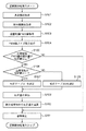
以上のような構成の光学機器における姿勢検出情報の補正方法について図6のフローチャートを用いて説明する。なお本フローチャートは、温度変化に対して2パターンの補正テーブルを持つ場合についてのものであるが、本発明はこれに限定されるものではなく、さらに多くのテーブルもしくは補正計算式を持つ(複数記憶している)場合に対しても同様に適用可能である。 A method for correcting posture detection information in the optical apparatus having the above-described configuration will be described with reference to the flowchart of FIG. Although this flowchart is for the case of having two patterns of correction tables for temperature changes, the present invention is not limited to this, and has more tables or correction calculation formulas (multiple storage formulas). The same applies to the case of
姿勢検知のスタートは一定周期、例えば40msecおきに実行される。姿勢検知処理がスタートするとまずステップS101にて、光学機器の温度情報の取得が実行される。次に、ステップS102にて補正レンズの位置制御にかかわる積分補償値の取得が実行される。次にステップS103にて位置制御にかかわる制御量をPWMに変換した値が取得される。補正レンズの位置制御は常にフィードバック制御をおこなっているため、リアルタイムにPWM値が変化する。そのため、このPWM値をそのまま姿勢検知情報の補正に使用した場合、高周波なノイズ成分によって姿勢判定が頻繁に切り替わってしまう恐れがある。そのため、ステップS104にて、取得したPWM値にローパスフィルタあるいは平均化処理を行うことで、ノイズの除去を行う。 The start of posture detection is executed at a constant cycle, for example, every 40 msec. When the attitude detection process is started, first, temperature information of the optical device is acquired in step S101. Next, in step S102, an integral compensation value related to the position control of the correction lens is acquired. In step S103, a value obtained by converting a control amount related to position control into PWM is acquired. Since the position control of the correction lens is always feedback control, the PWM value changes in real time. Therefore, when this PWM value is used as it is for correcting posture detection information, posture determination may be frequently switched by a high-frequency noise component. Therefore, in step S104, noise is removed by performing a low-pass filter or an averaging process on the acquired PWM value.
次にステップS105にてS104で算出したPWM値が規定値以上かどうか、即ち補正レンズ103の位置が比例領域か比例領域外であるかを判定する。規定値は、図7(b)の測定から算出した補正テーブルにより決定され、理論値と実際の電流が一致する領域と電流値が非線形となる領域の切り替わりのPWM値を設定する。S105にてS104で算出したPWM値が規定値以上でない場合には、PWM値と電流値が非線形な領域を使用していないことから、姿勢判定に用いる積分補償値を補正する必要はなくステップS111に進み、従来通り姿勢検知の判定を行う。
Next, in step S105, it is determined whether the PWM value calculated in S104 is equal to or greater than a specified value, that is, whether the position of the
S105にてS104で算出したPWM値が規定値以上の場合はステップS106に進み、光学機器の温度に応じて補正テーブルの設定を変更する。このとき、光学機器の温度が規定値以上であれば、ステップS107にて補正テーブル1を設定し、規定値以下ならステップS108にて補正テーブル2を設定する。設定された補正テーブルによってステップS109にて補正量を算出し、ステップS110にて姿勢検出のための積分補償値から補正量を減算して、ステップS111の姿勢判定を行い、姿勢検知処理を終了する。 If the PWM value calculated in S104 is greater than or equal to the specified value in S105, the process proceeds to step S106, and the correction table setting is changed according to the temperature of the optical device. At this time, if the temperature of the optical device is equal to or higher than the specified value, the correction table 1 is set in step S107. In step S109, the correction amount is calculated based on the set correction table. In step S110, the correction amount is subtracted from the integral compensation value for posture detection. The posture determination in step S111 is performed, and the posture detection processing is terminated. .
(第2の実施形態)
実施形態1においては、S105にてS104で算出したPWM値が規定値以上の場合はステップS106に進み、光学機器の温度に応じて補正テーブルの設定を変更した。しかしながら、本実施形態においては、補正レンズ103の位置が比例領域であるか否かの積分補償値の閾値がROMに記憶されているものとする。そして、閾値以上となる複数点でのシフトレンズ位置とその位置に応じた積分補償器401の理論値を記憶しておく。そして、S105にて補正レンズ103の位置が比例領域を外れる場合は、補正レンズ位置に応じた積分補償器401の理論値を読み出す。この理論値は1つの値でも良いし、温度の関数であっても良い。さらに、一つの位置で複数の温度に応じて理論値が記憶されていても良い。
(Second Embodiment)
In the first embodiment, when the PWM value calculated in S104 in S105 is equal to or larger than the specified value, the process proceeds to Step S106, and the setting of the correction table is changed according to the temperature of the optical device. However, in this embodiment, it is assumed that the integral compensation value threshold value indicating whether or not the position of the
(その他の実施形態)
上述した実施形態においては、補正レンズ103の位置が比例領域でない場合は、補正値を温度によって補正したり、理論値に置き換えたりした。しかしながら、補正レンズ103の位置が比例領域でない場合、単に姿勢判定を行わずに前回の姿勢を保持したままでも良い。
(Other embodiments)
In the above-described embodiment, when the position of the
以上の実施形態によれば、振れ補正の駆動に関する信号で姿勢検知を行う光学機器において、より大きな手振れ角度を実現するために補正レンズを大きなストロークで駆動した場合でも、正確な姿勢検知を行うことが可能となる。 According to the above embodiment, in an optical device that performs posture detection using a signal related to shake correction driving, accurate posture detection can be performed even when the correction lens is driven with a large stroke in order to achieve a larger camera shake angle. Is possible.
上述した実施形態では、主に静止画像の撮影を行うためのデジタルカメラだけでなく、デジタルビデオカメラ、一眼レフカメラの交換レンズ、撮影機能付きの電子機器などにも利用可能である。 The above-described embodiments can be used not only for digital cameras for mainly taking still images, but also for digital video cameras, interchangeable lenses for single-lens reflex cameras, electronic devices with a shooting function, and the like.
Claims (9)
前記光学機器の振れを検出する振れ検出手段と、
撮影画像のブレを補正するための補正部材の位置を検出する位置検出手段と、
前記振れ検出手段と前記位置検出手段の検出結果に応じて、前記補正部材の、撮影画像のブレを補正するための駆動量を演算する演算手段と、を有し、
前記演算手段は、前記振れ検出手段と前記位置検出手段の検出結果に対して積分制御を実行することで前記駆動量を演算し、
前記姿勢検知手段は、前記積分制御にて得られる信号を抽出し、該抽出された積分制御にて得られる信号を用いて前記光学機器の姿勢を検知し、
前記信号補正手段は、前記駆動量の大きさが所定値以上となる場合に、前記抽出された積分制御にて得られる信号を補正することを特徴とする光学機器。 An optical device having a function of correcting a signal used by the posture detection unit for detecting the posture of the optical device by a signal correction unit,
Shake detection means for detecting shake of the optical instrument;
Position detecting means for detecting the position of a correction member for correcting blurring of a captured image;
Calculating means for calculating a driving amount of the correction member for correcting blurring of a captured image in accordance with detection results of the shake detection means and the position detection means;
The calculation means calculates the drive amount by executing integral control on the detection results of the shake detection means and the position detection means,
The posture detection means extracts a signal obtained by the integration control, detects a posture of the optical device using a signal obtained by the extracted integration control,
The optical apparatus according to claim 1, wherein the signal correction unit corrects the signal obtained by the extracted integration control when the magnitude of the driving amount is equal to or greater than a predetermined value.
前記光学機器の振れを検出する振れ検出工程と、
撮影画像のブレを補正するための補正部材の位置を検出する位置検出工程と、
前記振れ検出工程と前記位置検出工程での検出結果に応じて、前記補正部材の、撮影画像のブレを補正するための駆動量を演算する演算工程と、を有し、
前記演算工程では、前記振れ検出工程と前記位置検出工程での検出結果に対して積分制御を実行することで前記駆動量を演算し、
前記姿勢検知工程では、前記積分制御にて得られる信号を抽出し、該抽出された積分制御にて得られる信号を用いて前記光学機器の姿勢を検知し、
前記信号補正工程では、前記駆動量の大きさが所定値以上となる場合に、前記抽出された積分制御にて得られる信号を補正することを特徴とする光学機器の制御方法。 A control method of an optical device having a function of correcting a signal used in a posture detection step of detecting a posture of the optical device in a signal correction step,
A shake detection step of detecting shake of the optical instrument;
A position detecting step for detecting a position of a correction member for correcting blurring of a captured image;
A calculation step of calculating a driving amount for correcting blurring of a captured image of the correction member according to detection results in the shake detection step and the position detection step;
In the calculation step, the driving amount is calculated by executing integration control on the detection results in the shake detection step and the position detection step,
In the posture detection step, a signal obtained by the integration control is extracted, and a posture of the optical apparatus is detected using a signal obtained by the extracted integration control,
In the signal correction step, when the magnitude of the drive amount is equal to or greater than a predetermined value, a signal obtained by the extracted integral control is corrected.
Priority Applications (1)
| Application Number | Priority Date | Filing Date | Title |
|---|---|---|---|
| JP2011120989A JP5809450B2 (en) | 2011-05-30 | 2011-05-30 | Optical apparatus and control method thereof |
Applications Claiming Priority (1)
| Application Number | Priority Date | Filing Date | Title |
|---|---|---|---|
| JP2011120989A JP5809450B2 (en) | 2011-05-30 | 2011-05-30 | Optical apparatus and control method thereof |
Publications (3)
| Publication Number | Publication Date |
|---|---|
| JP2012247709A JP2012247709A (en) | 2012-12-13 |
| JP2012247709A5 JP2012247709A5 (en) | 2014-07-03 |
| JP5809450B2 true JP5809450B2 (en) | 2015-11-10 |
Family
ID=47468179
Family Applications (1)
| Application Number | Title | Priority Date | Filing Date |
|---|---|---|---|
| JP2011120989A Expired - Fee Related JP5809450B2 (en) | 2011-05-30 | 2011-05-30 | Optical apparatus and control method thereof |
Country Status (1)
| Country | Link |
|---|---|
| JP (1) | JP5809450B2 (en) |
Families Citing this family (4)
| Publication number | Priority date | Publication date | Assignee | Title |
|---|---|---|---|---|
| US9291876B2 (en) | 2013-05-29 | 2016-03-22 | Allegro Microsystems, Llc | System and method for controlling a motor |
| JP6458374B2 (en) * | 2014-07-02 | 2019-01-30 | リコーイメージング株式会社 | Imaging apparatus, imaging method, drive control apparatus, and drive control method |
| JP6525652B2 (en) * | 2015-03-18 | 2019-06-05 | キヤノン株式会社 | Image blurring correction apparatus, optical apparatus, imaging apparatus and control method |
| JP6590541B2 (en) * | 2015-06-11 | 2019-10-16 | オリンパス株式会社 | Blur correction device |
Family Cites Families (2)
| Publication number | Priority date | Publication date | Assignee | Title |
|---|---|---|---|---|
| JP2003177442A (en) * | 2001-12-07 | 2003-06-27 | Nikon Corp | Lens driver and method of adjusting lens driver |
| JP5305970B2 (en) * | 2009-02-17 | 2013-10-02 | キヤノン株式会社 | Image blur correction apparatus, optical apparatus including the same, imaging apparatus, and image blur correction apparatus control method and program |
-
2011
- 2011-05-30 JP JP2011120989A patent/JP5809450B2/en not_active Expired - Fee Related
Also Published As
| Publication number | Publication date |
|---|---|
| JP2012247709A (en) | 2012-12-13 |
Similar Documents
| Publication | Publication Date | Title |
|---|---|---|
| JP5868042B2 (en) | Anti-shake control device, imaging device, and control method for anti-shake control device | |
| JP6045154B2 (en) | Image blur correction apparatus, optical apparatus including the same, image pickup apparatus, and image blur correction apparatus control method | |
| US9325885B2 (en) | Image stabilization apparatus and control method therefor | |
| US11523059B2 (en) | Image stabilization apparatus, image stabilization control method, and computer-readable storage medium | |
| US8190009B2 (en) | Optical apparatus and control method thereof, and image pickup apparatus | |
| US9513492B2 (en) | Shake correction apparatus and control method | |
| JP2013130720A (en) | Vibration control device, control method thereof and imaging device | |
| JP6513903B2 (en) | Camera module, position control method of optical element thereof and portable device | |
| JP5809450B2 (en) | Optical apparatus and control method thereof | |
| US9398220B2 (en) | Shake correction apparatus and image pickup apparatus thereof, and optical device mountable on image pickup apparatus | |
| US9563068B2 (en) | Image shake correction device, control method thereof, and image pickup apparatus | |
| JP2009147675A (en) | Imaging apparatus | |
| JP6274558B2 (en) | Shake correction device, shake correction method and program, and imaging device | |
| JP2013003168A (en) | Vibration-proof control device, vibration-proof control method, imaging apparatus and control method thereof | |
| JP6395401B2 (en) | Image shake correction apparatus, control method therefor, optical apparatus, and imaging apparatus | |
| JP2017044878A (en) | Image-capturing device and control method therefor | |
| JP5053920B2 (en) | Image shake correction apparatus, optical apparatus including the same, imaging apparatus, and image shake correction apparatus control method | |
| JP2014092756A (en) | Image shake correcting device, optical equipment comprising the same, imaging device, and control method of image shake correcting device | |
| JP5744495B2 (en) | Optical apparatus and control method thereof | |
| JP5053693B2 (en) | Image blur correction apparatus or optical apparatus and image pickup apparatus including the same | |
| US10989894B2 (en) | Lens driving apparatus, control method therefor, storage medium storing control program therefor, and image pickup apparatus | |
| JP5967885B2 (en) | Optical apparatus, imaging apparatus including the same, and control method of optical apparatus | |
| JP2016008995A (en) | Lens barrel and imaging device | |
| JP6592289B2 (en) | Imaging apparatus, control method therefor, program, and storage medium | |
| JP2015161692A (en) | Electronic device, and optical apparatus |
Legal Events
| Date | Code | Title | Description |
|---|---|---|---|
| A521 | Request for written amendment filed |
Free format text: JAPANESE INTERMEDIATE CODE: A523 Effective date: 20140519 |
|
| A621 | Written request for application examination |
Free format text: JAPANESE INTERMEDIATE CODE: A621 Effective date: 20140519 |
|
| A977 | Report on retrieval |
Free format text: JAPANESE INTERMEDIATE CODE: A971007 Effective date: 20150226 |
|
| A131 | Notification of reasons for refusal |
Free format text: JAPANESE INTERMEDIATE CODE: A131 Effective date: 20150327 |
|
| A521 | Request for written amendment filed |
Free format text: JAPANESE INTERMEDIATE CODE: A523 Effective date: 20150526 |
|
| A131 | Notification of reasons for refusal |
Free format text: JAPANESE INTERMEDIATE CODE: A131 Effective date: 20150626 |
|
| A521 | Request for written amendment filed |
Free format text: JAPANESE INTERMEDIATE CODE: A523 Effective date: 20150713 |
|
| TRDD | Decision of grant or rejection written | ||
| A01 | Written decision to grant a patent or to grant a registration (utility model) |
Free format text: JAPANESE INTERMEDIATE CODE: A01 Effective date: 20150814 |
|
| A61 | First payment of annual fees (during grant procedure) |
Free format text: JAPANESE INTERMEDIATE CODE: A61 Effective date: 20150911 |
|
| R151 | Written notification of patent or utility model registration |
Ref document number: 5809450 Country of ref document: JP Free format text: JAPANESE INTERMEDIATE CODE: R151 |
|
| LAPS | Cancellation because of no payment of annual fees |