JP5809445B2 - Laser processing apparatus and method - Google Patents
Laser processing apparatus and method Download PDFInfo
- Publication number
- JP5809445B2 JP5809445B2 JP2011114374A JP2011114374A JP5809445B2 JP 5809445 B2 JP5809445 B2 JP 5809445B2 JP 2011114374 A JP2011114374 A JP 2011114374A JP 2011114374 A JP2011114374 A JP 2011114374A JP 5809445 B2 JP5809445 B2 JP 5809445B2
- Authority
- JP
- Japan
- Prior art keywords
- liquid
- gas
- processing
- laser
- containing liquid
- Prior art date
- Legal status (The legal status is an assumption and is not a legal conclusion. Google has not performed a legal analysis and makes no representation as to the accuracy of the status listed.)
- Expired - Fee Related
Links
Images


Description
本発明は、液中の被処理物にレーザ光を照射して該被処理物を処理するレーザ処理装置及び方法に関する。 The present invention relates to a laser processing apparatus and method for processing a processing object by irradiating the processing object in a liquid with a laser beam.
従来、特許文献1に記載されるレーザ光によるエッチング方法が知られている。このエッチングでは、純水中に置いた被加工物の加工箇所に気泡発生用レーザ光を照射して当該加工箇所を覆う気泡を形成し、この状態で、被加工物の前記加工箇所に加工用レーザ光を照射してエッチングを施している。このようなエッチング方法(処理方法)によれば、気泡発生用レーザ光によって加工箇所に形成された気泡が、加工用レーザ光によるエッチング加工に伴う残渣を当該加工箇所から分離させて浮上する。その結果、レーザエッチングに伴う被加工物の残渣による加工精度の低下を防止することができるようになる。
Conventionally, the etching method by the laser beam described in
また、特許文献2に記載される金属物体のレーザピーニング処理方法が知られている。この種のレーザピーニング処理方法では、水中に置かれた被処理物(金属物体)の表面に、高いピークパワー密度をもつパルスレーザビームが照射される。そして、このパルスレーザビームの照射により発生するプラズマの膨張反力により、被処理物に残留圧縮応力が付与される。 Moreover, the laser peening processing method of the metal object described in patent document 2 is known. In this type of laser peening treatment method, a surface of a workpiece (metal object) placed in water is irradiated with a pulsed laser beam having a high peak power density. Residual compressive stress is applied to the object to be processed by the expansion reaction force of the plasma generated by the irradiation of the pulse laser beam.
しかしながら、上述したようなレーザを用いて被処理物の表面を処理する技術では、前者の場合(エッチング方法)、被加工物における加工箇所近傍の純水を気泡発生用レーザ光の加熱によって気化させて気泡を形成させているので、多くの気泡を発生させるのに限界があり、効率的な残渣除去が難しい。また、後者の場合(レーザピーニング処理方法)では、残留圧縮応力を付与することにより被処理物の表面を改質することができるものの、その改質効果は限定的なものである。 However, in the technique of processing the surface of the workpiece using the laser as described above, in the former case (etching method), pure water in the vicinity of the processing portion of the workpiece is vaporized by heating the bubble generating laser beam. Since bubbles are formed, there is a limit to generating many bubbles, and it is difficult to efficiently remove residues. In the latter case (laser peening treatment method), the surface of the object to be treated can be modified by applying a residual compressive stress, but the modification effect is limited.
本発明は、このような事情に鑑みてなされたもので、レーザを用いて被処理物に対するより効果的な処理が可能となるレーザ処理装置及び方法を提供するものである。 The present invention has been made in view of such circumstances, and provides a laser processing apparatus and method capable of performing more effective processing on an object to be processed using a laser.
本発明に係るレーザ処理装置は、処理槽内において、液体の存在のもとで被処理物にレーザビームを照射して当該被処理物を処理するレーザ処理装置であって、気体供給機構と、液体中に前記気体供給機構からの気体の微細気泡を発生させて微細気泡含有液を生成する微細気泡含有液生成機構と、前記処理槽内において、少なくとも前記被処理物の処理すべき部位を前記微細気泡含有液生成機構からの微細気泡含有液が満たされた状態を形成する処理状態形成機構とを有し、前記微細気泡含有液生成機構は、前記レーザビームの波長と同程度のサイズ、あるいはそれより小さいサイズの微細気泡を最も多く含有する前記微細気泡含有液を生成し、前記微細気泡含有液が満たされた状態の前記被処理物の処理すべき部位に前記レーザビームを照射する構成となる。 A laser processing apparatus according to the present invention is a laser processing apparatus for processing a processing object by irradiating the processing object with a laser beam in the presence of a liquid in a processing tank, and a gas supply mechanism; wherein a gas microbubble-containing liquid generating mechanism for generating a fine-bubble-containing liquid by generating fine bubbles from the gas supply mechanism into the liquid, in the processing bath, the portion to be processed of at least the object to be processed A processing state forming mechanism that forms a state in which the microbubble-containing liquid from the microbubble-containing liquid generation mechanism is filled, and the microbubble-containing liquid generation mechanism has the same size as the wavelength of the laser beam, or generating said fine-bubble-containing liquid most containing fine bubbles of less than the size, the laser beam irradiation at the site said to be processed of the object in a state in which the fine-bubble-containing liquid is satisfied Configuration and made to be.
また、本発明に係るレーザ処理方法は、処理槽内において、液体の存在のもとで被処理物にレーザビームを照射して当該被処理物の表面を処理するレーザ処理方法であって、液体中に気体供給機構からの気体の微細気泡を発生させて微細気泡含有液を生成する微細気泡含有液生成ステップと、前記処理槽内において、少なくとも前記被処理物の処理すべき部位に前記微細気泡含有液生成機構からの微細気泡含有液が満たされた状態を形成する処理状態形成ステップと、前記微細気泡含有液が満たされた状態の前記被処理物の処理すべき部位に前記レーザビームを照射するレーザビーム照射ステップとを有し、前記微細気泡含有液生成ステップは、前記レーザビームの波長と同程度のサイズ、あるいはそれより小さいサイズの微細気泡を最も多く含有する前記微細気泡含有液を生成する構成となる。 The laser processing method according to the present invention is a laser processing method for processing a surface of an object to be processed by irradiating the object to be processed with a laser beam in the presence of the liquid in the processing tank. a gas microbubble-containing liquid generating step of generating a fine-bubble-containing liquid by generating fine bubbles from the gas supply mechanism in, in the processing bath, the fine bubbles at the site to be treated in at least the object to be processed A processing state forming step for forming a state filled with the fine bubble-containing liquid from the contained liquid generation mechanism, and irradiating the portion to be processed of the object to be processed in the state filled with the fine bubble-containing liquid with the laser beam have a laser beam irradiation step of the fine-bubble-containing liquid generating step, most multi microbubbles of the laser beam with a wavelength of about the same size or smaller than, The arrangement for generating the fine-bubble-containing liquid containing.
本発明に係るレーザ処理装置及び方法によれば、被処理物に対するより効果的な処理ができるようになる。 According to the laser processing apparatus and method of the present invention, more effective processing can be performed on an object to be processed.
以下、本発明の実施の形態について図面を用いて説明する。 Hereinafter, embodiments of the present invention will be described with reference to the drawings.
本発明の第1の実施の形態に係るレーザ処理装置は、図1に示すように構成される。このレーザ処理装置は、例えば、半導体ウェーハの表面に孔や溝を形成する等の加工を行うレーザ加工装置として機能する。 The laser processing apparatus according to the first embodiment of the present invention is configured as shown in FIG. This laser processing apparatus functions as, for example, a laser processing apparatus that performs processing such as forming holes and grooves on the surface of a semiconductor wafer.
図1において、このレーザ加工装置(レーザ処理装置)は、処理槽11、レーザユニット20、光学系ユニット21(レンズ等を含む)及び制御ユニット40を備えている。処理槽11内には、支持台12が設けられ、加工の対象となる半導体ウェーハ100(被処理物)が支持台12上に載置、固定される。処理槽11内には後述するように生成される微細気泡含有液W(気体含有液)が満たされ、支持台12に載置された半導体ウェーハ100が微細気泡含有液Wに浸っている。レーザユニット20として、例えば、約1μmの波長のレーザビームを出力するYAGレーザが用いられる。なお、後述するように、レーザビームの波長に応じて前記微細気泡含有液Wに含有される気泡のサイズが決められる。制御ユニット40の制御のもとレーザユニット20から出力されるレーザビームが光学系ユニット21を介して処理槽11内の支持台12に載置、固定された半導体ウェーハ100の加工すべき部位にフォーカスされた状態で照射されるようになっている。内部に支持台12の設けられた処理槽11は、制御ユニット40の制御に従って駆動される移動機構13によって2次元的に移動可能となっている。移動機構13による処理槽11の移動によって、支持台12に載置、固定された半導体ウェーハ100におけるレーザユニット20からのレーザビームの照射位置、即ち、加工位置を変えることができる。
In FIG. 1, the laser processing apparatus (laser processing apparatus) includes a
このレーザ加工装置は、更に、気体供給機構を備えるとともに、液体(純水)に前記気体供給機構からの気体の微細気泡を発生させて微細気泡含有液Wを生成する機構(微細気泡含有液生成機構(気体含有液生成機構))、及び該微細気泡含有液Wを処理槽11内の半導体ウェーハ100が浸るように当該処理槽11に供給するための機構(第1供給機構(処理状態形成機構))を備えている。それらの機構は、次のように構成されている。
This laser processing apparatus further includes a gas supply mechanism and a mechanism for generating fine bubble-containing liquid W by generating fine bubbles of gas from the gas supply mechanism in liquid (pure water) (fine bubble-containing liquid generation) Mechanism (gas-containing liquid generating mechanism)) and a mechanism (first supply mechanism (processing state forming mechanism) for supplying the microbubble-containing liquid W to the
処理槽11から延びる送通管15aがポンプ32の吸引口に接続され、その送通管15aにフィルタ31が設けられている。ポンプ32の排出口から延びる送通管15bが加圧槽36に接続され、その送通管15bに冷却機33が設けられている。送通管15bの冷却機33と加圧槽36との間には、気体供給器34(気体供給機構)から延びる送通管16が結合され、気体供給器34からの気体(空気、酸素、窒素、二酸化炭素等)が送通管16を通して送通管15bに供給されるようになっている。送通管16には開閉弁35が設けられており、開閉弁35の開閉によって気体供給器34からの気体の送通管15bへの供給、遮断の切換えが可能となる。加圧槽36から延びる送通管15cが処理槽11に至っており、その送通管15cに気泡発生ユニット38及び気泡弁別器39が設けられている。
A
ポンプ32の動作により処理槽11から吸引されて送通管15a、15bを流れる液体W(当初純水:処理槽内液)がフィルタ31及び冷却機33を通って加圧槽36に供給される。送通管15bを冷却機33から加圧槽36に流れる液体Wに気体供給器34から送通管16を通して供給される気体が混ぜられる。そして、その気体の混ぜられた液体Wは、ポンプ32の動作によって送通管15bを通して加圧槽36に圧送され、加圧槽36内に一時的に溜められる。加圧槽36では、前記気体の混ぜられた液体Wが加圧され、その液体W中に気体が溶融して、液体W中における気体の溶存濃度が上昇し、例えば、大気圧下に対して過飽和あるいはそれに近い状態となった気体溶存液が生成される。なお、加圧槽36内の圧力は、圧力調整器37によって調整可能となっている。
The liquid W (initially pure water: liquid in the processing tank) that is sucked from the
加圧槽36内に貯留された気体溶存液が加圧された状態を維持しつつ送通管15cを通って気泡発生ユニット38に供給される。気泡発生ユニット38は、複数のオリフィスを有しており、加圧状態の気体溶存液が複数のオリフィスを通過する際の圧力開放によって、液体(純水)中に微細気泡(バブルの大きさに応じて、例えば、マイクロバブル、マイクロナノバブル、ナノバブル等と呼ばれる)が発生する。気泡弁別器39は、気泡発生ユニット38からの微細気泡を含む液体Wに対してフィルタ処理、あるいは、遠心分離等の処理を施すことによって、レーザユニット20から照射されるレーザビームの波長(約1μm)と同程度のサイズ、あるいはそれより小さいサイズの微細気泡をそれより大きいサイズの微細気泡から弁別し、その弁別により得られたより小さいサイズの微細気泡を最も多く含有する液体(純水)、微細気泡含有液Wを排出する。この気泡弁別器39から排出される微細気泡含有液Wは、気泡によって白濁してレーザビームが透過しなかったり散乱したりして当該レーザビームの透過が妨げられることのない程度の透明度合いとなるような微細なサイズの気泡を含有するもので、好ましくは、前述したように、レーザビームの波長と同程度あるいはそれより小さいサイズの気泡、例えば、マイクロナノバブルやナノバブルを含有する。気泡弁別器39から排出される微細気泡含有液Wが、送通管15cを通して処理槽11に供給され、支持台12に載置、固定された半導体ウェーハ100全体を浸す。そして、ポンプ32によって処理槽11から吸引される微細気泡含有液Wが処理槽内液として送通管15a、15b、15cを流れる過程で、その処理槽内液が気体供給器34からの気体供給を受けて加圧槽36、気泡発生ユニット38及び気泡弁別器39を通って新たな微細気泡含有液として処理槽11に戻される。
The gas dissolved liquid stored in the pressurizing
なお、上述したレーザ加工装置において、加圧槽36、気泡発生ユニット38及び気泡弁別器39を用いて微細気泡含有液Wを生成する機構が前記微細気泡含有液生成機構(気体含有液生成機構)に相当する。また、気泡弁別器39から送通管15cを通して処理槽11内に置かれた半導体ウェーハ100が浸るように前記微細気泡含有液Wを処理槽11内に供給する機構が前記第1供給機構(処理状態形成機構)に相当する。
In the laser processing apparatus described above, the mechanism for generating the fine bubble-containing liquid W using the pressurizing
上述したようにして微細気泡含有液Wに浸った状態で処理槽11内に置かれた半導体ウェーハ100の表面の加工すべき部位に対してレーザユニット20からのレーザビームが照射される。その際、レーザビームのエネルギーによりそのレーザビームの照射された部位の加工(例えば、孔、溝等の形成加工)がなされるとともに、微細気泡含有液Wの多数の微細気泡(マイクロナノバブル、ナノバブル等)がそれより大きく浮上し易い多量の気泡として急速に顕在化する。そのため、その多量の気泡とともに前記加工により生じた残渣(加工クズ)が半導体ウェーハ100の表面から除去されるようになる。更に、元から微細気泡含有液W中に含まれていた微細な気泡が、溝等の加工部位中に入り込んで加工クズを吸着してその加工部位から排出することによって、その加工部位における残渣の盛り上がり(いわゆる、デブリ)を防ぐことができる。
As described above, the laser beam from the
このようにレーザビームのエネルギーにより半導体ウェーハ100の表面の処理すべき部位の加工がなされるとともにその部位から生じ得る残渣が多量の気泡によって除去され得るようになるので、半導体ウェーハ100に対してより効果的な加工ができるようになる。例えば、上述したように、孔や溝の加工において、その孔や溝の縁に発生し易い、いわゆる、デブリを極力少なくすることができる。
In this way, processing of a portion to be processed on the surface of the
なお、レーザ加工に際して、処理槽11内の微細気泡含有液W中に浮遊する加工クズが送通管15aに吸引されたとしても、その加工クズは、フィルタ31にて除去されるので、加工クズによってポンプ32や冷却機33が悪影響を受けることを防止することができる。また、送通管15bを通る液体Wが冷却機33によって冷却されるので、レーザビームのエネルギーによって加熱される処理槽11内の微細気泡含有液Wの温度が上昇することを極力抑えて微細気泡含有液Wの温度を安定化させることができる。従って、微細気泡含有液Wが循環供給されて再度加圧槽36に気体を溶融させる際に、温度が上昇することによって溶融させられる気体の量が減少してしまうことを防ぐことができる。
In addition, even when the processing waste floating in the fine bubble-containing liquid W in the
前述したレーザ加工装置では、半導体ウェーハ100のレーザ加工の行われる処理槽11内の微細気泡含有液Wをポンプ32が吸引することにより得られる処理槽内液に気体供給器34からの気体を加えて新たに生成される微細気泡含有液が処理槽11に戻されるようにしているが、処理槽11の微細気泡含有液Wを処理槽内液として得る機構や、その得られた処理槽内液に気体を加えて生成される新たな微細気泡含有液を処理槽11に戻す機構は、上述したものに限定されない。例えば、処理槽11からポンプ32を用いることなく落下する微細気泡含有液を処理槽内液として回収し、その回収した処理槽内液に気体を供給して生成される新たな微細気泡含有液を処理槽11に戻すような機構であってもよい。
In the laser processing apparatus described above, the gas from the
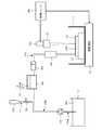
本発明の第2の実施の形態に係るレーザ処理装置は、図2に示すように構成される。このレーザ処理装置も第1の実施の形態の場合(図1参照)と同様に、半導体ウェーハの表面に孔や溝を形成する等の加工を行うレーザ加工装置として機能する。この第2の実施の形態に係るレーザ処理装置(レーザ加工装置)は、微細気泡含有液Wが処理槽11内に置かれた半導体ウェーハ100(被処理物)の表面に膜状に供給されることを特徴としている。なお、図2において、図1に示す部分と同じ部分については同一の参照番号が付されている。
The laser processing apparatus according to the second embodiment of the present invention is configured as shown in FIG. This laser processing apparatus also functions as a laser processing apparatus that performs processing such as forming holes and grooves on the surface of the semiconductor wafer, as in the case of the first embodiment (see FIG. 1). In the laser processing apparatus (laser processing apparatus) according to the second embodiment, the fine bubble-containing liquid W is supplied in the form of a film onto the surface of the semiconductor wafer 100 (object to be processed) placed in the
図2において、このレーザ加工装置では、第1の実施の形態の場合(図1参照)と同様に、制御ユニット40の制御に従って駆動される移動機構13によって2次元的に移動可能な処理槽11内に設けられた支持台12に加工の対象となる半導体ウェーハ100が載置、固定され、その半導体ウェーハ100の表面の加工すべき部位に制御ユニット40の制御のもとレーザユニット20から出射されるレーザビームが光学系ユニット21を通して照射されるようになっている。
In FIG. 2, in this laser processing apparatus, similarly to the case of the first embodiment (see FIG. 1), the
貯液槽14には液体(純水)Woが溜められており、ポンプ32の動作によって貯液槽14から吸引される液体Woが送通管15d、15bを通して加圧槽36に供給される。気体供給器34からの気体が送通管16を通して送通管15bを流れる液体Woに供給され、その気体が混ざった液体Woがポンプ32の動作によって加圧槽36に圧送される。加圧槽36での加圧によって液中の気体が溶解して生成される気体溶存液が送通管15cを流れる過程で、第1の実施の形態の場合(図1参照)と同様に、気泡発生ユニット38及び気泡弁別器39によってレーザビームの波長(例えば、1μm程度)と同程度あるはそれより小さい微細気泡を最も多く含む液体、微細気泡含有液Wが生成される。この場合も、第1の実施の形態の場合と同様に、気泡弁別器39から排出される微細気泡含有液Wは、気泡によって白濁してレーザビームが透過しなかったり散乱したりして当該レーザビームの透過が妨げられることのない程度の透明度合いとなるような微細なサイズの気泡を含有するもので、好ましくは、前述したように、レーザビームの波長と同程度あるいはそれより小さいサイズの気泡、例えば、マイクロナノバブルやナノバブルを含有する。そして、その微細気泡含有液Wが送通管15cから半導体ウェーハ100の表面に供給され、半導体ウェーハ100の表面に微細気泡含有液Wの液膜が形成される。
Liquid (pure water) Wo is stored in the
この第2の実施の形態に係るレーザ処理装置(レーザ加工装置)では、第1の実施の形態の場合(図1参照)と同様に加圧槽36、気泡発生ユニット38及び気泡弁別器39を用いて微細気泡含有液Wを生成する機構が本発明における微細気泡含有液生成機構(気体含有液生成機構)に相当する。また、気泡弁別器39から送通管15cを通して半導体ウェーハ100の表面に前記微細気泡含有液Wを供給する機構が本発明における第2供給機構(処理状態形成機構)に相当する。
In the laser processing apparatus (laser processing apparatus) according to the second embodiment, as in the case of the first embodiment (see FIG. 1), the pressurizing
この第2の実施の形態に係るレーザ処理装置(レーザ加工装置)もまた、第1の実施の形態の場合と同様に、レーザユニット20から照射されるレーザビームのエネルギーにより半導体ウェーハ100の表面の処理すべき部位の加工がなされるとともにその部位から生じ得る残渣が多量にかつ急速に顕在化される気泡によって除去され得るようになるので、半導体ウェーハ100に対するより効果的な加工ができるようになる。更に、元から微細気泡含有液W中に含まれていた微細な気泡が、溝等の加工部位中に入り込んで加工クズを吸着してその加工部位から排出することによって、その加工部位における残渣の盛り上がり(いわゆる、デブリ)を防ぐことができる。更に、半導体ウェーハ100の表面に供給される微細気泡含有液Wがその表面から流れ出して、レーザビームが照射される加工部位に常に新しい微細気泡含有液Wが満たされた状態になるので、気泡の効果を継続的に発揮させることができるとともに、その気泡とともにその加工部位から除去される残渣が半導体ウェーハ100の表面の他の部分に再付着することが防止される。
In the laser processing apparatus (laser processing apparatus) according to the second embodiment, the surface of the
本発明の第3の実施の形態に係るレーザ処理装置は、図3に示すように構成される。このレーザ処理装置も第1の実施の形態の場合(図1参照)及び第2の実施の形態の場合(図2参照)と同様に、半導体ウェーハの表面に孔や溝を形成する等の加工を行うレーザ加工装置として機能する。この第3の実施の形態に係るレーザ処理装置(レーザ加工装置)は、微細気泡含有液Wに代えて処理槽11に気体が高濃度にて溶解した気体溶存液が供給されることを特徴としている。なお、図3において、図1に示す部分と同じ部分については同一の参照符号が付されている。
The laser processing apparatus according to the third embodiment of the present invention is configured as shown in FIG. In this laser processing apparatus, as in the case of the first embodiment (see FIG. 1) and the case of the second embodiment (see FIG. 2), processing such as forming holes and grooves on the surface of the semiconductor wafer. It functions as a laser processing apparatus that performs the above. The laser processing apparatus (laser processing apparatus) according to the third embodiment is characterized in that a gas-dissolved liquid in which a gas is dissolved at a high concentration is supplied to the
図3において、図1に示す第1の実施の形態の場合(図1参照)と同様に、ポンプ32の動作により処理槽11から吸引されて送通管15a、15bを流れる液体(当初純水:処理槽内液)がフィルタ31及び冷却機33を通って加圧槽36に供給され、その過程で、送通管15bを流れる液体に気体供給器34からの気体が混ぜられる。そして、加圧槽36において、前記気体の混ぜられた液体が加圧され、その液体中に気体が溶融して、液体中の気体の溶存濃度が上昇し、例えば、大気圧下に対して過飽和あるいはそれに近い状態となった気体溶存液Wが生成される。加圧槽36からの気体溶存液Wが送通管15cを通して処理槽11に供給され、支持台12に載置、固定された半導体ウェーハ100全体を浸す。そして、ポンプ32によって処理槽11から吸引される気体溶存液Wが処理槽内液として送通管15a、15b、15cを流れる過程で、その処理槽内液が気体供給器34からの気体供給を受けて加圧槽36を通って新たな気体溶存液として処理槽11に戻される。
In FIG. 3, as in the case of the first embodiment shown in FIG. 1 (see FIG. 1), the liquid (initial pure water) that is sucked from the
この第3の実施の形態に係るレーザ処理装置(レーザ加工装置)では、加圧槽36を用いて気体溶存液を生成する機構が本発明における気体溶存液生成機構(気体含有液生成機構)に相当し、加圧槽36から送通管15cを通して処理槽11内に置かれた半導体ウェーハ100が浸るように前記気体溶存液を処理槽11内に供給する機構が本発明における第1供給機構(処理状態形成機構)に相当する。
In the laser processing apparatus (laser processing apparatus) according to the third embodiment, a mechanism for generating a gas-dissolved liquid using the pressurizing
上述したようにして気体溶存液Wに浸った状態で処理槽11内に置かれた半導体ウェーハ100の表面の加工すべき部位に対してレーザユニット20からのレーザビームが光学系ユニット21を介して照射される。その際、レーザビームのエネルギーによってそのレーザビームの照射された部位の加工がなされるとともに、そのレーザビームのエネルギーによって気体溶存液W内の溶存気体が浮上し易い多量の気泡として急速に顕在化する。そのため、その多量の気泡とともに前記加工により生じた残渣(加工クズ)が半導体ウェーハ100の表面から除去されるようになる。
As described above, the laser beam from the
この第3の実施の形態に係るレーザ処理装置(レーザ加工装置)によっても、第1の実施の形態の場合(図1参照)及び第2の実施の形態の場合(図2参照)と同様に、レーザビームによって加工される部位の周囲で発生する気泡によって半導体ウェーハ100に対してより効果的な加工ができるようになる。
Also by the laser processing apparatus (laser processing apparatus) according to the third embodiment, similarly to the case of the first embodiment (see FIG. 1) and the case of the second embodiment (see FIG. 2). The
なお、前述した第1の実施の形態(図1参照)、第2の実施の形態(図2参照)及び第3の実施の形態(図3参照)において、処理槽11が移動機構13によって移動される構成であったが、支持台12が処理槽11内において移動可能となる構成であっても、また、レーザユニット20及び光学系ユニット21が移動可能となる構成であってもよい。更に、レーザユニット20からのレーザビームが通過する光学系がレーザビームの進行方向を変えることにより当該レーザビームが半導体ウェーハ100(被処理物)を走査するように構成することもできる。例えば、2つのミラー(X・Y軸)を設けることによってレーザビームを二次元的に走査させることができる。このようにレーザビームを光学系によって走査させる場合、レーザユニット20や半導体ウェーハ(被処理物)を支持する部材を動かすことなく、光学系(例えば、ミラー)の調整によって半導体ウェーハ100のレーザビームによる走査が可能になる。
In the first embodiment (see FIG. 1), the second embodiment (see FIG. 2), and the third embodiment (see FIG. 3), the
また、第2の実施の形態(図2参照)では、半導体ウェーハ100の表面全体に微細気泡含有液W(気体含有液)の液膜が形成されるものであったが、半導体ウェーハ100の表面の少なくともレーザビームによって加工(処理)される部位に微細気泡含有液Wの液膜が形成されていればよい。また、第2の実施の形態(図2参照)において、微細気泡含有液Wに代えて、気体溶存液Wを半導体ウェーハ100(被処理物)の表面に供給するようにしてもよい。
In the second embodiment (see FIG. 2), the liquid film of the fine bubble-containing liquid W (gas-containing liquid) is formed on the entire surface of the
更に、前述した第3の実施の形態(図3参照)において、処理槽11を密閉構造にして、加圧槽36からの気体溶存液Wが加圧された状態を維持しつつ処理槽11に供給されるようにすることもできる。このようにすることで、高い気体溶存量を維持することができる。
Furthermore, in the third embodiment described above (see FIG. 3), the
本発明の第4の実施の形態に係るレーザ処理装置は、図4に示すように構成される。このレーザ処理装置は、例えば、金属体(被処理物)の表面にレーザビームを照射して金属体の表面部分に衝撃波を発生させて当該金属体の表面部分を改質(残留応力の除去、硬化等)させるレーザピーニング装置として機能する。 The laser processing apparatus according to the fourth embodiment of the present invention is configured as shown in FIG. This laser processing apparatus, for example, irradiates a surface of a metal body (object to be processed) with a laser beam to generate a shock wave on the surface of the metal body to modify the surface of the metal body (removal of residual stress, It functions as a laser peening apparatus for curing.
図4において、このレーザピーニング装置(レーザ処理装置)は、処理槽17、レーザユニット20、光学系ユニット21(レンズ等を含む)及び制御ユニット40を備えている。処理槽17は密閉された構造となっており、その内部に移動機構18、及びその移動機構18によって2次元的に移動可能となる支持台12が設けられ、ピーニングの対象となる金属体200(被処理物)が支持台12上に載置、固定されている。処理槽17内には後述するように生成される微細気泡含有液W(気体含有液)が満たされ、支持台12に載置された金属体200が微細気泡含有液Wに浸っている。処理槽17の上面に透明な窓17aが設けられており、制御ユニット40の制御のもとレーザユニット20(例えば、YAGレーザ)から出力されるレーザビームが光学系ユニット21及び窓17aを介して処理槽17内の支持台12に載置、固定された金属体200のピーニングすべき部位201にフォーカスされた状態で照射されるようになっている。制御ユニット40の制御に従って駆動される移動機構18による支持台12の移動によって、支持台12に載置、固定された金属体200におけるレーザユニット20からのレーザビームの照射位置、即ち、ピーニング位置を変えることができる。
In FIG. 4, the laser peening apparatus (laser processing apparatus) includes a
このレーザピーニング装置も、前述したレーザ加工装置(図1参照)と同様に、気体供給機構を備えるとともに、液体(純水)に前記気体供給機構からの気体の微細気泡を発生させて微細気泡含有液Wを生成する機構(微細気泡含有液生成機構(気体含有液生成機構))、及び該微細気泡含有液Wを処理槽17内の金属体200が浸るように当該処理槽11に供給するための機構(第1供給機構(処理状態形成機構))を備えている。それらの機構は、次のように構成されている。
This laser peening apparatus also includes a gas supply mechanism, as well as the laser processing apparatus (see FIG. 1) described above, and generates fine bubbles of gas from the gas supply mechanism in a liquid (pure water) to contain fine bubbles. A mechanism for generating the liquid W (fine bubble-containing liquid generation mechanism (gas-containing liquid generation mechanism)) and supplying the fine bubble-containing liquid W to the
液体(純水)Woを溜めた貯液槽14から延びる送通管15dがポンプ32の吸引口に接続され、ポンプ32の排出口から延びる送通管15bが加圧槽36に接続されている。送通管15bには、気体供給器34(気体供給機構)から延びる送通管16が結合され、気体供給器34からの気体(空気、酸素、窒素、二酸化炭素等)が送通管16を通して送通管15bに供給されるようになっている。送通管16には開閉弁35が設けられており、開閉弁35の開閉によって気体供給器34からの気体の送通管15bへの供給、遮断の切換えが可能となる。加圧槽36から延びる送通管15cが処理槽17に接続されており、その送通管15cに気泡発生ユニット38及び気泡弁別器39が設けられている。
A
ポンプ32の動作により貯液槽14から吸引されて送通管15d、15bを流れる液体Woに気体供給器34から送通管16を通して供給される気体が混ぜられる。そして、その気体の混ぜられた液体Woは、ポンプ32の動作によって送通管15bを通して加圧槽36に圧送される。加圧槽36での加圧作用によって液体Woに気体が溶融して、液体Woの気体の溶存濃度が上昇し、例えば、大気圧下に対して過飽和あるいはそれに近い状態となった気体溶存液が生成される。なお、加圧槽36の圧力は、圧力調整器37によって調整可能となっている。
The gas supplied from the
加圧槽36内に貯留された気体溶存液が加圧された状態を維持しつつ送通管15cを通して気泡発生ユニット38に供給される。気泡発生ユニット38は、複数のオリフィスを有しており、加圧状態の気体溶存液が複数のオリフィスを通過する際の圧力開放によって、液体(純水)Wo中に微細気泡が発生する。気泡弁別器39は、気泡発生ユニット38からの微細気泡を含む液体Wに対してフィルタ処理、あるいは、遠心分離等の処理を施すことによって、レーザユニット20から照射されるレーザビームの波長(約1μm)と同程度のサイズ、あるいはそれより小さいサイズの微細気泡をそれより大きいサイズの微細気泡から弁別し、その弁別により得られたより小さいサイズの微細気泡を含有する液体(純水)、微細気泡含有液Wを排出する。気泡弁別器39から排出される微細気泡含有液Wが、送通管15cを通して処理槽17に供給され、支持台12に載置、固定された金属体200全体を浸す。この場合も、第1の実施の形態及び第2の実施の形態の場合と同様に、気泡弁別器39から排出される微細気泡含有液Wは、気泡によって白濁してレーザビームが透過しなかったり散乱したりして当該レーザビームの透過が妨げられることのない程度の透明度合いとなるような微細なサイズの気泡を含有するもので、好ましくは、前述したように、レーザビームの波長と同程度あるいはそれより小さいサイズの気泡、例えば、マイクロナノバブルやナノバブルを最も多く含有する。
The gas dissolved liquid stored in the pressurizing
なお、上述したレーザピーニング装置において、加圧槽36、気泡発生ユニット38及び気泡弁別器39を用いて微細気泡含有液Wを生成する機構が本発明における微細気泡含有液生成機構(気体含有液生成機構)に相当する。また、気泡弁別器39から送通管15cを通して処理槽17内に置かれた金属体200が浸るように前記微細気泡含有液Wを処理槽17内に供給する機構が本発明における第1供給機構(処理状態形成機構)に相当する。
In the laser peening apparatus described above, the mechanism for generating the fine bubble-containing liquid W using the
上述したようにして微細気泡含有液Wに浸った状態で処理槽17内に置かれた金属体200の表面のピーニングすべき部位201に対してレーザユニット20からの高エネルギーのレーザビームが照射される。そのレーザビームにより金属体200の照射部位201や液体が気化したり、液体中に含まれる微細気泡が大量の気泡となって急速に顕在化したりプラズマ化したりすることによって、急激に発生した気体やプラズマによる衝撃波によって金属体200の照射部位201の改質がなされる(所謂、ピーニング)。これとともに、このとき生じたプラズマ中に含まれる元素(気体の元素、液体の元素、金属体200の元素)の全て、またはいずれかが反応することで新たな物質が形成され得る。その新たな物質が、例えば、液体W中や金属体200のピーニングされる部位201の表面に生成され得る。
As described above, a high-energy laser beam from the
例えば、金属体200を構成する亜鉛(Zn)と微細気泡含有液W中の酸素(O2)が反応して、酸化亜鉛(ZnO)が生成され得る(2Zn+O2=2ZnO)。この酸化亜鉛(ZnO)は透明電導膜を形成する材料として用いることができ、これをピーニング処理の副産物として生産し得ることは画期的なことである。
For example, zinc (Zn) constituting the
このように、第4の実施の形態に係るピーニング装置によれば、レーザビームにより発生するプラズマによる衝撃波によって金属体200の照射部位201の改質がなされるとともに、そのとき生じたプラズマ中に含まれる元素の全て、またはいずれかが反応することで新たな物質が形成され得るので、金属体200の照射部位201の改質自体が効果的になされ得るほか、更にその照射部位201の改質を越えた複数の元素の反応に基づく効果的な処理が可能となる。
As described above, according to the peening apparatus according to the fourth embodiment, the
本発明の第5の実施の形態に係るレーザ処理装置は、図5に示すように構成される。このレーザ処理装置も第4の実施の形態の場合(図4参照)と同様に、金属体(被処理物)の表面にレーザビームを照射して金属体の表面部分に衝撃波を発生させて当該金属体の表面部分を改質させるレーザピーニング装置として機能する。この第5の実施の形態に係るレーザ処理装置(ピーニング装置)は、微細気泡含有液Wに代えて処理槽17に気体の溶解した気体溶存液が供給されることを特徴としている。なお、図5において、図4に示す部分と同じ部分については同一の参照符号が付されている。
The laser processing apparatus according to the fifth embodiment of the present invention is configured as shown in FIG. Similarly to the case of the fourth embodiment (see FIG. 4), this laser processing apparatus also generates a shock wave on the surface of the metal body by irradiating the surface of the metal body with the laser beam. It functions as a laser peening apparatus for modifying the surface portion of the metal body. The laser processing apparatus (peening apparatus) according to the fifth embodiment is characterized in that a gas-dissolved liquid in which a gas is dissolved is supplied to the
図5において、第4の実施の形態の場合(図4参照)と同様に、密閉された処理槽17内に制御ユニット40の制御に従って駆動される移動機構18によって2次元的に移動可能な支持台12に金属材200が載置、固定され、その金属材200の表面のピーニングすべき部位201に制御ユニット40の制御のもとレーザユニット20から出力されるレーザビームが光学系ユニット21及び処理槽17の上面に設けられた透明の窓17aを通して照射されるようになっている。密閉された構造の処理槽17には、送通管15eによって加圧器50が接続されている。加圧器50によって内部が加圧される処理槽17の圧力は圧力調整器19によって調整できる。なお、圧力調整器19を省くこともできる。
In FIG. 5, as in the case of the fourth embodiment (see FIG. 4), the support is movable in a two-dimensional manner by a moving
また、図4に示す第4の実施の形態の場合と同様に、ポンプ32の動作により貯液槽14から吸引されて送通管15d、15bを流れる液体(純水)Woが加圧槽36に供給される過程で、送通管15bを流れる液体Woに気体供給器34からの気体が混ぜられる。そして、加圧槽36において、前記気体の混ぜられた液体が加圧され、その液体中に気体が溶融し、液体中の気体の溶存濃度が上昇し、例えば、大気圧下に対して過飽和あるいはそれに近い状態となった気体溶存液Wが生成される。加圧槽36からの気体溶存液Wが送通管15cを通して処理槽17に供給され、支持台12に載置、固定された金属体200全体を浸す。
Similarly to the case of the fourth embodiment shown in FIG. 4, the liquid (pure water) Wo that is sucked from the
なお、上述したレーザピーニング装置において、加圧槽36を用いて気体溶存液Wを生成する機構が本発明における気体溶存液生成機構(気体含有液生成機構)に相当する。また、加圧槽36から送通管15cを通して処理槽17内に置かれた金属体200が浸るように前記気体溶存液Wを処理槽17内に供給する機構が本発明における第1供給機構(処理状態形成機構)に相当する。
In the laser peening apparatus described above, the mechanism for generating the gas dissolved liquid W using the pressurizing
上述したように処理槽17に満たされた気体溶存液Wは、加圧器50による加圧によって高い気体の溶存濃度が維持される。このように高い気体の溶存濃度の維持された気体溶存液Wに浸った状態で処理槽17内に置かれた金属体200の表面のピーニングすべき部位201に対してレーザユニット20からの高エネルギーのレーザビームが光学系ユニット21を介して照射される。そのレーザビームにより金属体200の照射部位201や液体が気化したり、液体中に溶存した気体が大量の気泡となって急速に顕在化したりプラズマ化したりすることによって、急激に発生した気体やプラズマによる衝撃波によって金属体200の照射部位201の改質がなされる(所謂、ピーニング)。これとともに、このとき生じたプラズマ中に含まれる元素(気体の元素、液体の元素、金属体200の元素)の全て、またはいずれかが反応することで新たな物質が形成され得る。その新たな物質が、例えば、液体W中や金属体200のピーニングされる部位201の表面に生成され得る。そのため、金属体200の照射部位201の改質自体が効果的になされ得るほか、更にその表面改質を越えた複数の元素の反応に基づく効果的な処理が可能となる。
As described above, the gas dissolved liquid W filled in the
本発明の第6の実施の形態に係るレーザ処理装置は、図6に示すように構成される。このレーザ処理装置も第4の実施の形態の場合(図4参照)及び第5の実施の形態の場合(図5参照)と同様に、金属体(被処理物)の表面にレーザビームを照射して金属体の表面部分に衝撃波を発生させて当該金属体の表面部分を改質させるレーザピーニング装置として機能する。この第6の実施の形態に係るレーザ処理装置(ピーニング装置)は、複数種の気体のうちの少なくとも一種を液体に溶解すべき気体として選択することができることを特徴としている。なお、図6において、図5に示す部分と同じ部分については、同一の参照符号が付されている。 The laser processing apparatus according to the sixth embodiment of the present invention is configured as shown in FIG. Similarly to the case of the fourth embodiment (see FIG. 4) and the case of the fifth embodiment (see FIG. 5), this laser processing apparatus also irradiates the surface of the metal body (object to be processed) with a laser beam. Thus, it functions as a laser peening apparatus for generating a shock wave on the surface portion of the metal body to modify the surface portion of the metal body. The laser processing apparatus (peening apparatus) according to the sixth embodiment is characterized in that at least one of a plurality of gases can be selected as a gas to be dissolved in a liquid. In FIG. 6, the same parts as those shown in FIG.
図6において、このレーザピーニング装置は、第1の気体(例えば、酸素)を供給する第1気体供給器34aと、第1気体供給器34aから供給される気体と異なる、第2の気体(例えば、窒素)を供給する第2気体供給器34bとを有している。貯液槽14からの液体(純水)Woが流れる送通管15bに接続された送通管16cが2つの分岐管16a、16bに分岐している。送通管16cには開閉弁35cが、一方の分岐管16aには開閉弁35aが、他方の分岐管16bには開閉弁35bが、それぞれ設けられている。第1気体供給器34aからの第1の気体が分岐管16a及び送通管16cを通して送通管15bを流れる液体Woに供給可能となっている。また、第2気体供給器34bからの第2の気体が分岐管16b及び送通管16cを通して送通管15bを流れる液体Woに供給可能となっている。
In FIG. 6, this laser peening apparatus includes a first
なお、図6に示すレーザピーニング装置の他の構成については、図5に示すものと同じである。また、この場合、第5の実施の形態の場合(図5参照)と同様に、加圧槽36を用いて気体溶存液Wを生成する機構が本発明における気体溶存液生成機構(気体含有液生成機構)に相当し、加圧槽36から送通管15cを通して処理槽17内に置かれた金属体200が浸るように前記気体溶存液Wを処理槽17内に供給する機構が本発明における第1供給機構(処理状態形成機構)に相当する。
The other configuration of the laser peening apparatus shown in FIG. 6 is the same as that shown in FIG. In this case, as in the case of the fifth embodiment (see FIG. 5), the mechanism for generating the gas-dissolved liquid W using the pressurizing
このようなレーザピーニング装置では、第1の気体(例えば、酸素)の溶存液を利用する場合、第1気体供給器34aに接続された分岐管16aの開閉弁35aと送通管16cの開閉弁35cとが開放されるとともに、第2気体供給器34bに接続された分岐管16bの開閉弁35bが閉鎖される。これにより、貯液槽14からの液体Woに第1の気体が混ぜられ、その第1の気体の混ざった液体が加圧槽36にて加圧される。そして、加圧槽36にて生成される第1の気体が高濃度にて溶解した液体、第1の気体溶存液(例えば、酸素溶存液)Wが加圧槽36から処理槽17に供給される。
In such a laser peening apparatus, when a dissolved liquid of the first gas (for example, oxygen) is used, the on-off
この場合、処理槽17に置かれた金属体200の高エネルギーのレーザビームの照射される部位201のピーニングが、その周囲の多量の第1の気体がレーザビームによって急速に顕在化した気泡が存在する環境のもとでなされる。その際、第1の気体(気泡の元素)と液体の元素、あるいは、金属体200の元素との反応によって新たな物質(例えば、酸化物)が、その金属体200の前記部位201の表面に形成され、あるいは、液体W中に生成され得る。
In this case, the peening of the
また、第2の気体(例えば、窒素)の溶存液を利用する場合、第2の気体を供給する第2気体供給器34bに接続された分岐管16bの開閉弁35bと送通管16cの開閉弁35cとが開放されるとともに、第1気体供給器34aに接続された分岐管16aが閉鎖される。これにより、貯液槽14からの液体Woに第2の気体が混ぜられ、その第2の気体の混ざった液体が加圧槽36にて加圧される。そして、加圧槽36にて生成される第2の気体が高濃度にて溶解した液体、第2の気体溶存液(例えば、窒素溶存液)Wが加圧槽36から処理槽17に供給される。
Further, when using a dissolved liquid of the second gas (for example, nitrogen), the open /
この場合、処理槽17に置かれた金属体200の高エネルギーのレーザビームの照射される部位201のピーニングが、その周囲の多量の第2の気体がレーザビームによって急速に顕在化した気泡が存在する環境のもとでなされる。その際、第2の気体と液体や金属体200の元素との反応によって新たな物質が生成され得る。
In this case, the peening of the
上述したようなレーザピーニング装置(図6参照)によれば、第5の実施の形態の場合(図5参照)と同様に、気泡の存在のもとに金属体200のレーザビームの照射される部位201の効果的なピーニングが可能になるとともに、複数の元素の反応により生成され得る新たな物質を、供給する気体を切換えることにより種々変えることができるようになる。
According to the laser peening apparatus as described above (see FIG. 6), similarly to the case of the fifth embodiment (see FIG. 5), the laser beam of the
なお、切換え供給可能な気体は、2種に限らず、3種以上の気体(例えば、酸素、オゾン、窒素、水素、二酸化炭素、不活性ガス等)を切換え供給することも可能である。また、利用される気体は一種に限らず、二種以上であってもよい。図6に示すレーザピーニング装置では、開閉弁35a、35b及び35cを開放することにより、第1の気体と第2の気体の双方が貯液槽14からの液体Woに混ぜられ、その液体Wが加圧槽36により加圧されることにより、第1の気体及び第2の気体の双方が高い濃度で溶解した気体溶存液が生成される。そして、処理槽17では、第1の気体及び第2の気体の双方が高い濃度で溶解した気体溶存液Wの存在のもと、前述したような金属体200に対するレーザピーニングの処理がなされる。この場合、気体溶存液Wに含まれる2種の気体の元素相互やそれらの元素と他の元素との反応が期待でき、それらの反応によって新たな物質が生成され得る。
The gas that can be switched and supplied is not limited to two, and three or more gases (for example, oxygen, ozone, nitrogen, hydrogen, carbon dioxide, inert gas, etc.) can be switched and supplied. Moreover, the gas used is not limited to one type, but may be two or more types. In the laser peening apparatus shown in FIG. 6, both the first gas and the second gas are mixed with the liquid Wo from the
本発明の第7の実施の形態に係るレーザ処理装置は、図7に示すように構成される。このレーザ処理装置も第4の実施の形態の場合(図4参照)、第5の実施の形態の場合(図5参照)及び第6の実施の形態の場合(図6参照)と同様に、金属体(被処理物)の表面にレーザビームを照射して金属体の表面部分に衝撃波を発生させて当該金属体の表面部分を改質させるレーザピーニング装置として機能する。この第7の実施の形態に係るレーザ処理装置(ピーニング装置)は、ピーニングに際して得られた新たな物質を回収する機能を有していることを特徴とする。なお、図7において、図5に示す部分と同じ部分については、同一の参照符号が付されている。 The laser processing apparatus according to the seventh embodiment of the present invention is configured as shown in FIG. This laser processing apparatus is also similar to the case of the fourth embodiment (see FIG. 4), the case of the fifth embodiment (see FIG. 5) and the case of the sixth embodiment (see FIG. 6). It functions as a laser peening apparatus that irradiates the surface of a metal body (object to be processed) with a laser beam to generate a shock wave on the surface portion of the metal body to modify the surface portion of the metal body. The laser processing apparatus (peening apparatus) according to the seventh embodiment has a function of collecting a new substance obtained at the time of peening. In FIG. 7, the same parts as those shown in FIG.
図7において、密閉された構造の処理槽17には、送通管15fによって生成物質回収装置60が接続されている。生成物質回収装置60は、処理槽17内の液体Wを吸引して、その液体W中から浮遊する物質を抽出、回収する。送通管15fには開閉弁61が設けられている。
In FIG. 7, a generated
なお、図7に示すレーザピーニング装置の他の構成については、図5に示すものと同じである。また、この場合、第5の実施の形態の場合(図5参照)と同様に、加圧槽36を用いて気体溶存液Wを生成する機構が本発明における気体溶存液生成機構(気体含有液生成機構)に相当し、加圧槽36から送通管15cを通して処理槽17内に置かれた金属体200が浸るように前記気体溶存液Wを処理槽17内に供給する機構が本発明における第1供給機構(処理状態形成機構)に相当し、また、処理槽17に接続される送通管15f及び生成物質回収装置60が本発明における生成物質回収機構に相当する。
The other configuration of the laser peening apparatus shown in FIG. 7 is the same as that shown in FIG. In this case, as in the case of the fifth embodiment (see FIG. 5), the mechanism for generating the gas-dissolved liquid W using the pressurizing
このようなレーザピーニング装置では、処理槽17と生成物質回収装置60とを結ぶ送通管15fに設けられた開閉弁61が閉じられた状態で、処理槽17に置かれた金属体200の高エネルギーのレーザビームの照射される部位201のピーニングが、その周囲に多量の気体含有液Wから顕在化された多数の気泡が存在する環境のもとでなされる。その際、気体の元素(気泡の元素)と液体の元素、あるいは、気体の元素と金属体200の元素との反応によって新たな物質(例えば、酸化物)が、その金属体200の前記部位201の表面に形成され、あるいは、液体W中に生成され得る。
In such a laser peening apparatus, the height of the
そして、ピーニングが終了した後に、開閉弁61が開放され、生成物回収装置60の吸引作用によって処理槽17内の液体Wが送通管15fを通して生成物回収装置60内に取り込まれる。そして、生成物回収装置60では、取り込んだ液体Wに浮遊する前記反応によって生成された物質が液体Wから分離されて回収される。
After the peening is completed, the on-off
上述したようなレーザピーニング装置(図7参照)によれば、第5の実施の形態の場合(図5参照)と同様に、気泡の存在のもとに金属体200のレーザビームの照射される部位201の効果的なピーニングが可能になるとともに、新たな物質が液中に形成され、あるいは、ピーニングされる部位201の表面に形成される。そして、更に、液中に形成された新たな物質を生成物回収装置60によって効率的に回収することができる。
According to the laser peening apparatus as described above (see FIG. 7), similarly to the case of the fifth embodiment (see FIG. 5), the laser beam of the
なお、第6の実施の形態(図6参照)及び第7の実施の形態(図7参照)において、処理槽17内には、気体溶存液に代えて、第4の実施の形態の場合(図4参照)と同様に、微細気泡含有液を供給するようにしてもよい。
In addition, in 6th Embodiment (refer FIG. 6) and 7th Embodiment (refer FIG. 7), it replaces with gas dissolved liquid in the
また、前述した第4の実施の形態乃至第7の実施の形態(図4乃至図7参照)において、気体を溶解させる液体は、純水であったが、これに限られず、他の種類の液体、例えば、イオンや化学物質の溶存した水、油、有機溶液(アルコール等)であってもよい。この場合、その液体を構成する元素に依存した新規な物質を生成することができるようになる。 In the fourth to seventh embodiments (see FIGS. 4 to 7) described above, the liquid for dissolving the gas is pure water. It may be a liquid, for example, water, oil or organic solution (alcohol or the like) in which ions or chemical substances are dissolved. In this case, it becomes possible to generate a new substance depending on the elements constituting the liquid.
前述した第4の実施の形態乃至第7の実施の形態(図4乃至図7参照)において、被処理物である金属体200は、微細気泡含有液や気体溶存液に全体的に浸っていなくても、例えば、図2に示す第2の実施の形態の場合のように、ピーニングすべき部位201(照射部位)が微細気泡含有液や気体溶存液にて覆われていればよい。
In the above-described fourth to seventh embodiments (see FIGS. 4 to 7), the
また、第1の実施の形態乃至第7の実施の形態(図1乃至図7参照)において、被処理物(半導体ウェーハ100、金属体200)のレーザビームの照射部位の広さは、光学系21によりレーザスポットのサイズを調整することにより処理の目的にあったものにすることができる。例えば、広い範囲の加工やピーニングを行う場合には、レーザスポットのサイズを大きく調整し、微細な穴開け加工等の場合には、レーザスポットのサイズを小さく調整することができる。
Further, in the first to seventh embodiments (see FIGS. 1 to 7), the width of the laser beam irradiation portion of the object to be processed (
更に、図1乃至図3に示すレーザ加工装置における処理槽11は上方が開放するものであったが、図4乃至図7に示すレーザピーニング装置における処理槽17と同様に、密閉された構造でレーザビームが透過する透明な窓が設けられるものであってもよい。また、逆に、図4乃至図7に示すレーザピーニング装置における処理槽17は、図1乃至図3に示すレーザ加工装置における処理槽11と同様に、上方が開放するものであってもよい。
Furthermore, although the
また、第1の実施の形態乃至第5の実施の形態及び第7の実施の形態(図1乃至図5及び図7参照)において、第6の実施の形態と同様に、複数種の気体から選択される少なくとも一種を含む気体含有液(微小気泡含有液、気体溶存液)を生成し、被処理物(半導体ウェーハ100、金属体200)をその気体含有液の存在のもとに、レーザビームによって処理(加工、ピーニング)するようにすることもできる。
Further, in the first to fifth embodiments and the seventh embodiment (see FIGS. 1 to 5 and 7), as in the sixth embodiment, a plurality of kinds of gases are used. A gas-containing liquid (a microbubble-containing liquid or a gas-dissolved liquid) containing at least one selected is generated, and the object to be processed (
また、図中において、処理槽11、17に供給される液体は、処理槽11、17の端から供給されているが、加工点近くに向けて供給するようにしてもよい。このようにすることによって、液体がすばやく置換され、処理効率が向上する。また、供給する口は、移動するように構成されていてもよい。こうすることによって、満遍なく、微細気泡含有液あるいは気体溶存液を処理槽全体に供給することができ、被処理物が均一に処理できる。
In the drawing, the liquid supplied to the
気泡弁別器39は、気泡発生ユニット38からの微細気泡を含む液体Wに対してフィルタ処理、あるいは、遠心分離等の処理を施すことによって、レーザユニット20から照射されるレーザビームの波長(約1μm)と同程度のサイズ、あるいはそれより小さいサイズの微細気泡をそれより大きいサイズの微細気泡から弁別するとしているが、これに限られず、一定時間、タンク等に溜めおき、マイクロナノバブル、ナノバブル以上のサイズの気泡が浮上するのを待って、処理槽11、17に供給する構成を有するものであってもよい。
The
11、17 処理槽
12 支持台
13、18 移動機構
14 貯液槽
15a、15b、15c、15d、15e、15f 送通管
16 送通管
19 圧力調整器
20 レーザユニット
21 光学系ユニット
31 フィルタ
32 ポンプ
33 冷却機
34 気体供給器
35 開閉弁
36 加圧槽
37 圧力調整器
38 気体発生ユニット
39 気体弁別器
40 制御ユニット
50 加圧器
60 生成物回収器
DESCRIPTION OF
Claims (4)
気体供給機構と、
液体中に前記気体供給機構からの気体の微細気泡を発生させて微細気泡含有液を生成する微細気泡含有液生成機構と、
前記処理槽内において、少なくとも前記被処理物の処理すべき部位を前記微細気泡含有液生成機構からの微細気泡含有液が満たされた状態を形成する処理状態形成機構とを有し、
前記微細気泡含有液生成機構は、前記レーザビームの波長と同程度のサイズ、あるいはそれより小さいサイズの微細気泡を最も多く含有する前記微細気泡含有液を生成し、
前記微細気泡含有液が満たされた状態の前記被処理物の処理すべき部位に前記レーザビームを照射するレーザ処理装置。 In a processing tank, a laser processing apparatus for processing a target object by irradiating the target object with a laser beam in the presence of a liquid,
A gas supply mechanism;
A fine bubble-containing liquid generating mechanism for generating a fine bubble-containing liquid by generating gas fine bubbles from the gas supply mechanism in the liquid;
A treatment state forming mechanism for forming a state in which at least a portion to be processed of the workpiece is filled with the fine bubble-containing liquid from the fine bubble-containing liquid generation mechanism in the treatment tank;
The fine bubble-containing liquid generating mechanism generates the fine bubble-containing liquid containing the largest number of fine bubbles having the same size as the wavelength of the laser beam or smaller.
The laser processing apparatus which irradiates the laser beam to the site | part which should process the said to-be-processed object of the state with which the said microbubble containing liquid was satisfy | filled.
液体中に気体供給機構からの気体の微細気泡を発生させて微細気泡含有液を生成する微細気泡含有液生成ステップと、
前記処理槽内において、少なくとも前記被処理物の処理すべき部位に前記微細気泡含有液生成機構からの微細気泡含有液が満たされた状態を形成する処理状態形成ステップと、
前記微細気泡含有液が満たされた状態の前記被処理物の処理すべき部位に前記レーザビームを照射するレーザビーム照射ステップとを有し、
前記微細気泡含有液生成ステップは、前記レーザビームの波長と同程度のサイズ、あるいはそれより小さいサイズの微細気泡を最も多く含有する前記微細気泡含有液を生成するレーザ処理方法。 In a processing tank, a laser processing method for processing a surface of a processing object by irradiating the processing object with a laser beam in the presence of a liquid,
A fine bubble-containing liquid generating step for generating fine bubble-containing liquid by generating fine bubbles of gas from the gas supply mechanism in the liquid; and
In the processing tank, a processing state forming step of forming a state in which at least a portion to be processed of the workpiece is filled with the fine bubble-containing liquid from the fine bubble-containing liquid generation mechanism;
A laser beam irradiation step of irradiating the laser beam to a site to be processed of the object to be processed in a state where the fine bubble-containing liquid is filled,
The fine bubble-containing liquid producing step is a laser processing method for producing the fine bubble-containing liquid containing the largest number of fine bubbles having a size comparable to or smaller than the wavelength of the laser beam.
Priority Applications (1)
| Application Number | Priority Date | Filing Date | Title |
|---|---|---|---|
| JP2011114374A JP5809445B2 (en) | 2011-05-23 | 2011-05-23 | Laser processing apparatus and method |
Applications Claiming Priority (1)
| Application Number | Priority Date | Filing Date | Title |
|---|---|---|---|
| JP2011114374A JP5809445B2 (en) | 2011-05-23 | 2011-05-23 | Laser processing apparatus and method |
Related Child Applications (1)
| Application Number | Title | Priority Date | Filing Date |
|---|---|---|---|
| JP2015179649A Division JP5992081B2 (en) | 2015-09-11 | 2015-09-11 | Laser processing equipment |
Publications (3)
| Publication Number | Publication Date |
|---|---|
| JP2012240099A JP2012240099A (en) | 2012-12-10 |
| JP2012240099A5 JP2012240099A5 (en) | 2014-07-03 |
| JP5809445B2 true JP5809445B2 (en) | 2015-11-10 |
Family
ID=47462340
Family Applications (1)
| Application Number | Title | Priority Date | Filing Date |
|---|---|---|---|
| JP2011114374A Expired - Fee Related JP5809445B2 (en) | 2011-05-23 | 2011-05-23 | Laser processing apparatus and method |
Country Status (1)
| Country | Link |
|---|---|
| JP (1) | JP5809445B2 (en) |
Families Citing this family (4)
| Publication number | Priority date | Publication date | Assignee | Title |
|---|---|---|---|---|
| JP6125261B2 (en) | 2013-02-12 | 2017-05-10 | 三菱重工業株式会社 | Water jet peening compressive residual stress test method |
| JP5997804B1 (en) * | 2015-06-03 | 2016-09-28 | 株式会社Ihi | Surface treatment equipment |
| JP6571711B2 (en) | 2017-04-03 | 2019-09-04 | ファナック株式会社 | Laser equipment |
| JP7165079B2 (en) * | 2019-03-12 | 2022-11-02 | 日本タングステン株式会社 | MACHINING COOLANT SUPPLY MECHANISM AND MACHING COOLANT SUPPLY METHOD |
Family Cites Families (5)
| Publication number | Priority date | Publication date | Assignee | Title |
|---|---|---|---|---|
| US5057184A (en) * | 1990-04-06 | 1991-10-15 | International Business Machines Corporation | Laser etching of materials in liquids |
| JPH06333910A (en) * | 1993-05-27 | 1994-12-02 | Nippondenso Co Ltd | Laser etching method |
| JPH11145108A (en) * | 1997-11-05 | 1999-05-28 | Denso Corp | Method and device of fine work device |
| JP2005324238A (en) * | 2004-05-17 | 2005-11-24 | Toyota Motor Corp | Method and apparatus for laser beam machining |
| JP2011088799A (en) * | 2009-10-26 | 2011-05-06 | Mitsubishi Electric Corp | Method of manufacturing semiconductor device and laser machining device |
-
2011
- 2011-05-23 JP JP2011114374A patent/JP5809445B2/en not_active Expired - Fee Related
Also Published As
| Publication number | Publication date |
|---|---|
| JP2012240099A (en) | 2012-12-10 |
Similar Documents
| Publication | Publication Date | Title |
|---|---|---|
| JP5992081B2 (en) | Laser processing equipment | |
| JP5809445B2 (en) | Laser processing apparatus and method | |
| EP1834708A2 (en) | Substrate cleaning method, substrate cleaning system and program storage medium | |
| JP2006520534A (en) | Laser processing using activity support gas | |
| JP2011040747A (en) | Gas-assisted laser ablation | |
| JP2003246638A (en) | Glass structure and method of manufacturing the same | |
| JP5017882B2 (en) | Hybrid laser processing method | |
| JPWO2007063987A1 (en) | Processing and cleaning method and apparatus using ultrapure water plasma bubbles | |
| JP2010256274A (en) | Decontamination device and method of decomtaminating radioactive material | |
| TW201922396A (en) | Laser processing apparatus | |
| JP2010120038A (en) | Laser beam machining apparatus and method | |
| KR102051183B1 (en) | Apparatus and method of treating with laser beam | |
| JP2007253120A (en) | Ultrasonic cleaning method | |
| TW201914721A (en) | Laser processing apparatus | |
| JP2006218544A (en) | Hybrid machining device and method | |
| AU759331B2 (en) | Foam control | |
| CN108620737A (en) | The method that laser direct-writing glass surface prepares optical microstructures | |
| CN110587147A (en) | Laser processing apparatus | |
| JP2009136912A (en) | Method and apparatus for processing of transparent material | |
| JP5089313B2 (en) | Substrate processing apparatus and processing method | |
| JP3492032B2 (en) | Laser marking method and apparatus | |
| JP2020189263A (en) | Apparatus and method for generating nanoparticles | |
| JP6612015B2 (en) | Substrate processing apparatus and substrate processing method | |
| JP6863880B2 (en) | Metal nanocolloid generation method and metal nanocolloid generation device | |
| Jiao et al. | Statistical analysis of femtosecond pulses laser on hole drilling of silicon wafer |
Legal Events
| Date | Code | Title | Description |
|---|---|---|---|
| A521 | Written amendment |
Free format text: JAPANESE INTERMEDIATE CODE: A523 Effective date: 20140515 |
|
| A621 | Written request for application examination |
Free format text: JAPANESE INTERMEDIATE CODE: A621 Effective date: 20140515 |
|
| A977 | Report on retrieval |
Free format text: JAPANESE INTERMEDIATE CODE: A971007 Effective date: 20150227 |
|
| A131 | Notification of reasons for refusal |
Free format text: JAPANESE INTERMEDIATE CODE: A131 Effective date: 20150325 |
|
| A521 | Written amendment |
Free format text: JAPANESE INTERMEDIATE CODE: A523 Effective date: 20150518 |
|
| TRDD | Decision of grant or rejection written | ||
| A01 | Written decision to grant a patent or to grant a registration (utility model) |
Free format text: JAPANESE INTERMEDIATE CODE: A01 Effective date: 20150826 |
|
| A61 | First payment of annual fees (during grant procedure) |
Free format text: JAPANESE INTERMEDIATE CODE: A61 Effective date: 20150911 |
|
| R150 | Certificate of patent or registration of utility model |
Ref document number: 5809445 Country of ref document: JP Free format text: JAPANESE INTERMEDIATE CODE: R150 |
|
| LAPS | Cancellation because of no payment of annual fees |