JP5808237B2 - Connector and drive mechanism - Google Patents
Connector and drive mechanism Download PDFInfo
- Publication number
- JP5808237B2 JP5808237B2 JP2011270265A JP2011270265A JP5808237B2 JP 5808237 B2 JP5808237 B2 JP 5808237B2 JP 2011270265 A JP2011270265 A JP 2011270265A JP 2011270265 A JP2011270265 A JP 2011270265A JP 5808237 B2 JP5808237 B2 JP 5808237B2
- Authority
- JP
- Japan
- Prior art keywords
- axis
- rod
- cylindrical portion
- connector
- cylindrical
- Prior art date
- Legal status (The legal status is an assumption and is not a legal conclusion. Google has not performed a legal analysis and makes no representation as to the accuracy of the status listed.)
- Expired - Fee Related
Links
Images




Landscapes
- Mutual Connection Of Rods And Tubes (AREA)
- Joining Of Building Structures In Genera (AREA)
Description
本発明は、棒体を接続する接続具及びこれを用いた駆動機構に関するものである。 The present invention relates to a connector for connecting rods and a drive mechanism using the same.
従来、棒体同士を接続する接続具として、下記の特許文献1又は特許文献2に記載されたような接続具がある。これらの接続具は、第1の棒体を保持する保持部と、当該第1の棒体に直交する第2の棒体を保持する保持部とを有し、第1の棒体と第2の棒体とをT字形に接続するものである。
Conventionally, there exists a connection tool as described in the following
この種の接続具にあっては、第1及び第2の棒体からの荷重による変形を規制するために、また、荷重によって容易に破損しないようにするために、所定の剛性と強度とが要求される。その一方で、安易に剛性と強度とを追求すれば、接続具の重量が大きくなってしまうが、この種の接続具においては軽量化が特に望まれる用途もあり得る。 In this type of connector, in order to restrict deformation due to the load from the first and second rods and not to be easily damaged by the load, predetermined rigidity and strength are required. Required. On the other hand, if the rigidity and strength are easily pursued, the weight of the connecting device will increase, but this type of connecting device may have applications in which weight reduction is particularly desired.
そこで、本発明は、極端に重量を増加させることなく剛性と強度とを確保し易い接続具及びこれを用いた駆動機構を提供することを目的とする。 Therefore, an object of the present invention is to provide a connector that can easily ensure rigidity and strength without extremely increasing the weight, and a drive mechanism using the connector.
本発明の接続具は、第1の棒体と第2の棒体とを接続する接続具であって、第1の軸線上に延在する第1の棒体が挿入される第1の筒部と、第1の軸線に交差する第2の軸線上に延在する第2の棒体が、一端面を第1の棒体の外側面に向けた状態で挿入される第2の筒部と、第1の筒部の外側面から第2の筒部の端部まで延び、第1の筒部と第2の筒部とを連結する連結部と、を備え、連結部には、第1の軸線の方向に貫通する貫通穴が形成されていると共に、貫通穴を複数の領域に仕切るように当該貫通穴の貫通方向に延び略平板状をなす補強リブが形成されており、第1及び第2の軸線の双方を含む平面に投射した形状においては、連結部の幅は、第1の筒部に近い位置ほど広く、第1の軸線に直交する平面に投射した形状においては、連結部の最大幅は第2の筒部の幅よりも大きく、連結部の最大幅が現れる位置は第1の筒部よりも第2の筒部に近く、補強リブは、貫通穴の内側面のうち第2の軸線が通過する位置から、連結部の最大幅が現れる部分と第1の筒部の内側面とを結ぶ最短の線分の略中央の位置に向けて、略直線状に延びている。 The connection tool of the present invention is a connection tool for connecting a first rod body and a second rod body, and the first tube into which the first rod body extending on the first axis is inserted. And a second cylindrical portion in which a second rod extending on a second axis that intersects the first axis is inserted with one end surface facing the outer surface of the first rod And a connecting portion that extends from the outer surface of the first tube portion to the end portion of the second tube portion and connects the first tube portion and the second tube portion. A through hole penetrating in the direction of one axis is formed, and a reinforcing rib having a substantially flat plate shape is formed extending in the through direction of the through hole so as to partition the through hole into a plurality of regions. In the shape projected on the plane including both the second axis and the width of the connecting portion is wider as the position is closer to the first cylindrical portion, and in the shape projected on the plane orthogonal to the first axis, The maximum width of the connecting portion is larger than the width of the second cylindrical portion, the position where the maximum width of the connecting portion appears is closer to the second cylindrical portion than the first cylindrical portion, and the reinforcing rib is the inner surface of the through hole. From the position through which the second axis passes, extending substantially linearly toward the position of the center of the shortest line segment connecting the portion where the maximum width of the connecting portion appears and the inner surface of the first cylindrical portion. ing.
本発明の接続具では、第1の筒部の外側面と、第2の筒部と連結部との接続部と、の間の距離が、第1の筒部の外径の0.7〜1.5倍であることが好ましい。 In the connection tool of the present invention, the distance between the outer surface of the first tube portion and the connection portion between the second tube portion and the connecting portion is 0.7 to 0.7 of the outer diameter of the first tube portion. It is preferably 1.5 times.
第1の軸線に直交する平面に投射した形状における連結部の最大幅が、第2の筒部の外径の1.1〜1.7倍であることが好ましい。 It is preferable that the maximum width of the connecting portion in the shape projected onto the plane orthogonal to the first axis is 1.1 to 1.7 times the outer diameter of the second cylindrical portion.
本発明の接続具は、第1の棒体を第1の筒部内で第1の軸周りに回転させる用途、又は第1の棒体を中心にして第1の軸周りに回転する用途に用いられることが好ましい。 The connection tool of the present invention is used for an application in which the first rod body is rotated around the first axis in the first cylindrical portion, or an application in which the first rod body is rotated around the first axis around the first rod body. It is preferred that
本発明の接続具は、第1の筒部は第1の軸線を筒軸とする円筒形状をなし、第1の棒体は第1の筒部の内側面に摺接する円柱面を外側面として有していることが好ましい。 In the connector according to the present invention, the first cylindrical portion has a cylindrical shape with the first axis as the cylindrical axis, and the first rod body has a cylindrical surface slidably in contact with the inner surface of the first cylindrical portion as an outer surface. It is preferable to have.
本発明の駆動機構は、上記何れかの接続具と、接続具の第1の筒部に挿入され、外側面を第1の筒部の内側面に摺動させる第1の棒体と、を備え、第1の棒体は、第1の筒部内で第1の軸周りに回転し、第1の筒部の内側面と第1の棒体の外側面との動摩擦係数が、JIS K7125試験で測定した場合に、0.5以下である。 The drive mechanism of the present invention includes any one of the above-described connecting devices, and a first rod body that is inserted into the first tube portion of the connecting device and slides the outer surface to the inner surface of the first tube portion. The first rod body rotates around the first axis in the first tube portion, and the dynamic friction coefficient between the inner surface of the first tube portion and the outer surface of the first rod portion is JIS K7125 test. Is 0.5 or less.
本発明の駆動機構は、上記何れかの接続具と、接続具の第1の筒部に挿入され、外側面を第1の筒部の内側面に摺動させる第1の棒体と、を備え、接続具は、第1の棒体を中心にして第1の軸周りに回転し、第1の筒部の内側面と第1の棒体の外側面との動摩擦係数が、JIS K7125試験で測定した場合に、0.5以下である。 The drive mechanism of the present invention includes any one of the above-described connecting devices, and a first rod body that is inserted into the first tube portion of the connecting device and slides the outer surface to the inner surface of the first tube portion. The connecting tool rotates around the first axis around the first rod, and the dynamic friction coefficient between the inner surface of the first tube and the outer surface of the first rod is JIS K7125 test. Is 0.5 or less.
本発明によれば、極端に重量を増加させることなく剛性と強度とを確保し易い接続具及びこれを用いた駆動機構を提供することができる。 ADVANTAGE OF THE INVENTION According to this invention, the connection tool which can ensure rigidity and intensity | strength without increasing a weight extremely, and a drive mechanism using the same can be provided.
以下、図面を参照しつつ本発明に係る接続具及び駆動機構の実施形態について詳細に説明する。 Hereinafter, embodiments of a connector and a drive mechanism according to the present invention will be described in detail with reference to the drawings.
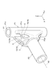
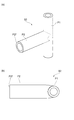
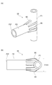
図1〜図5には、本発明の接続具の一実施形態である接続具1を示す。図1〜図5に示すようにXYZ座標系を設定し、各部位の位置関係の説明にX,Y,Zを用いる場合がある。なお、各図は接続具1の形状の一例を示すものであり、接続具1の形状を限定するものではない。
1 to 5 show a
接続具1は、第1棒体(第1の棒体)B1と第2棒体(第2の棒体)B2とを保持して両者を接続する接続具である。第1棒体B1は、Z軸に平行な仮想の第1軸線(第1の軸線)A1上に延在し、第2棒体B2はX軸に平行な仮想の第2軸線(第2の軸線)A2上に延在している。
The
接続具1は、第1軸線A1を筒軸とする円筒状の第1円筒部(第1の筒部)P1を備えている。更に、接続具1は、第2軸線A2を筒軸とする円筒状の第2円筒部(第2の筒部)P2を備えている。第1円筒部には第1棒体B1が挿入され、第2円筒部には、第2棒体B2が挿入される。第1棒体B1及び第2棒体B2が接続具1に保持された状態においては、第2棒体B2の一端面B2aが第1棒体B1の外側面B1bに向けられるように配置され、第1棒体B1と第2棒体B2とがT字に配置される。
The
なお、図2に示されるように、本実施形態では、第1棒体B1及び第2棒体B2がともに断面円形をなし、第1棒体B1の外径は第1円筒部P1の内径にほぼ等しく、第2棒体B2の外径は第2円筒部P2の内径にほぼ等しいものとする。また、第1棒体B1の直径は、第2棒体B2の直径の0.5〜2倍が望ましい。第1棒体B1及び第2棒体B2は、中実の棒であってもよく、中空のパイプであってもよい。 As shown in FIG. 2, in the present embodiment, both the first rod B1 and the second rod B2 have a circular cross section, and the outer diameter of the first rod B1 is equal to the inner diameter of the first cylindrical portion P1. The outer diameter of the second rod body B2 is substantially equal to the inner diameter of the second cylindrical portion P2. The diameter of the first rod B1 is preferably 0.5 to 2 times the diameter of the second rod B2. The first rod B1 and the second rod B2 may be solid rods or hollow pipes.
第1棒体B1は、カシメや接着等により第1円筒部P1に固定されてもよく、Z方向への並進移動や第1軸線A1周りの回転が可能であってもよい。第2棒体B2は、カシメや接着等により第2円筒部P2に固定されてもよく、X方向への並進移動や第2軸線A2周りの回転が可能であってもよい。 The first rod B1 may be fixed to the first cylindrical portion P1 by caulking or adhesion, etc., it may be capable of rotation around the translational movement and the first axis A1 in the Z direction. The second rod body B2 may be fixed to the second cylindrical portion P2 by caulking or adhesion, etc., we may be capable of rotation of translational movement and the second around the axis A2 in the X-direction.
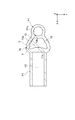
接続具1は、第1円筒部P1と第2円筒部P2とを連結する連結部3を備えている。連結部3は、第1円筒部P1の外側面P1bから第2円筒部P2の端部P2aまでX方向に延びている。図3に示すように、XZ平面(第1軸線A1及び第2軸線A2の双方を含む平面)に投射した形状においては、Z方向に測った連結部3の幅3zは、第1円筒部P1に近い位置ほど広くなっている。また、図4に示すように、XY平面(第1軸線A1に直交する平面)に投射した形状においては、Y方向に測った連結部3の最大幅3ymは第2円筒部P2の幅P2yよりも大きい。また、連結部3の最大幅3ymが現れる位置(点3qの位置)は、第1円筒部P1よりも第2円筒部P2に近い。
The
連結部3には、Z方向に貫通する貫通穴10が形成されている。また、連結部3には、貫通穴10を3つの領域11,12,13に仕切る2つの補強リブ5,5が形成されている。補強リブ5,5は、Z方向に延び略平板状をなしている。
A through
上記補強リブ5,5が設けられる位置について説明する。図5は、貫通穴10内の補強リブ5,5を取り除いた状態を示す接続具1の断面図である。図4にも示されるとおり、2つの補強リブ5,5はXZ平面に対して対称に設けられるので、以下では、一方の補強リブ5についてのみ図示しながら説明し重複する説明を省略する。
The position where the reinforcing
図5に示すように、XY平面に投射した形状において、貫通穴10の内側面10b上で第2軸線A2が通過する点のうち、第2円筒部P2に近い方を点11sとする。連結部3の最大幅3ym(図4参照)が現れる部分における、連結部3の外側面上の点を点3qとする。点3qと第1円筒部P1の内側面P1cとを結ぶ最短の線分を線分13とする。線分13の略中点を点13sとする。補強リブ5は、Z方向に延びると共に、XY平面に投射した形状においては、図5に2点鎖線で示すように、点11sから点13sに向けて略直線状に延びている。
As shown in FIG. 5, in the shape projected on the XY plane, a point closer to the second cylindrical portion P2 is defined as a
また、図3に示すように、接続具1をXZ平面に投射した形状において、第1円筒部P1の外側面P1bから、第2円筒部P2の端部P2a(第2円筒部P2と連結部3との接続部)までの距離15が、第1円筒部P1の外径D1bの0.7〜1.5倍であることとしてもよい。また、図4に示すように、接続具1をXY平面に投射した形状において、連結部3の最大幅3ymが、第2円筒部P2の外径D2bの1.1〜1.7倍であることとしてもよい。
Further, as shown in FIG. 3, in the shape in which the
接続具1は、第1棒体B1を第1円筒部P1内で第1軸線A1周りに回転させる用途に用いられてもよい。このような用途の接続具1としては、図8に示す接続具1C(詳細は後述する)が例として挙げられる。接続具1は、第1棒体B1を中心にして第1軸線A1周りに回転する用途に用いられてもよい。このような用途の接続具1としては、図6及び図7に示す接続具1A,1B(詳細は後述する)が例として挙げられる。また、接続具1においては、第1円筒部P1は第1軸線A1を筒軸とする円筒形状をなし、第1棒体B1は第1円筒部P1の内側面P1cに摺接する外側面B1b(円柱面)を有していることとしてもよい。この構造の接続具1としては、図8に示す接続具1Cが例として挙げられる。
The
図6に示すスプロケット組立体120は、接続具1Aと、自転車用ペダル121と、スプロケット122と、が一体的に連結されて構成されている。ペダル121は、接続具1Aの第2円筒部P2に挿入されて固定されており、第2棒体B2に相当する。スプロケット122の中央部は、接続具1Aの第1円筒部P1の一端面に固定される。自転車の車体側に設けられた回転軸123は、第1棒体B1に相当する。軸線A1上に延びる回転軸123は、スプロケット122の中心を貫通し第1円筒部P1内に挿入されている。第1円筒部P1は、所定の軸受部材(図示せず)を介して回転軸123に軸支されている。スプロケット組立体120の全体が第1軸線1A周りに回転することで、スプロケット122に架設された自転車用チェーン(図示せず)が駆動される。
The
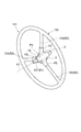
図7に示すホイール組立体131は、自転車用のホイール133と、接続具1Bと、が一体的に連結されて構成されている。接続具1Bは、第1円筒部P1と、3つの第2円筒部P2とを備えている。第2円筒部P2は、それぞれ連結部3を介して第1円筒部P1の外壁面に等間隔に接続されている。ホイール133が有する3つのスポーク135は、接続部1Bの第2円筒部P2に挿入されて固定されており、第2棒体B2に相当する。自転車の車体側に設けられた回転軸137は、第1棒体B1に相当する。軸線A1上に延びる回転軸137は、第1円筒部P1内に挿入されている。第1円筒部P1は、所定の軸受部材(図示せず)を介して回転軸137に軸支されており、ホイール組立体131全体が、第1軸線1A周りに回転する。
The
図8に示す駆動機構151は、自動車のワイパーを駆動する機構であり、本発明に係る駆動機構の一実施形態である。駆動機構151は接続具1Cを備えている。
A
接続具1Cは、図1〜図5に示す接続具1の構成に加えて、第1円筒部P1の外側面P1bに設けられた取付片7を有している。接続具1Cは取付片7をもって自動車の車体フレーム(図示せず)にボルトで固定される。図8に示すように、駆動機構151は対称に配置された2つの接続具1C、1Cを2つ備えており、接続具1C,1C同士は、自動車の車幅方向に延びる棒材104で接続されている。棒材104は第2棒体B2に相当し、棒材104の一端は、一方の接続具1Cの第2円筒部P2に挿入され固定されている。棒材104の他端は、他方の接続具1Cの第2円筒部P2に挿入され固定されている。
1 C of connection tools have the
ワイパー102の回転軸103は、第1棒体B1に相当する。回転軸103は、軸線A1上に延在しており第1円筒部P1内に挿入されている。回転軸103の上端は第1円筒部P1の上端から上方に突出しており、回転軸103の上端にはワイパー102が取り付けられている。回転軸103の外側面103bは、第1円筒部P1の内側面P1cに摺接している。外側面103bと内側面P1cとが円周方向に滑ることにより、回転軸103が接続具1Cに対して軸線A周りに回転可能である。回転軸103の下端には、径方向に延びる駆動アーム103aが取り付けられている。また、接続具1C、1C同士の間にモータ105が設置されており、モータ105は、回転アーム106を水平回転させる。回転アーム106と駆動アーム103aとは、接続アーム107で接続されている。回転アーム106がモータ105によって水平回転されると、接続アーム107を介して駆動アーム103a及び回転軸103が往復回動し、その結果、ワイパー102が往復回動する。
The
以上のとおり、駆動機構151は、接続具1Cと、接続具1Cの第1円筒部P1に挿入され、外側面103b(外側面B1b;図1参照)を第1円筒部P1の内側面P1cに摺動させる回転軸103(第1棒体B1)と、を備えており、回転軸103は、第1円筒部P1内で軸線A1周りに回転する。なお、本発明の駆動機構の他の例として、接続具1と、接続具1の第1円筒部P1に挿入され、外側面B1bを第1円筒部P1の内側面P1cに摺動させる第1棒体B1と、を備え、接続具1は、第1棒体B1を中心にして軸線A周りに回転する機構であってもよい。
As described above, the
これらのように、第1円筒部P1の内側面P1cと第1棒体B1の外側面B1bとを摺動させながら第1円筒部P1と第1棒体B1とを相対的に回転させる駆動機構においては、内側面P1cと外側面B1bとの動摩擦係数が、0.5以下であることが好ましい。この構成により、接続具1又は第1棒体B1が円滑に回転する。上記の場合の動摩擦係数とは、JIS K7125に規定された動摩擦係数測定試験で測定される動摩擦係数をいう。
As described above, the drive mechanism that relatively rotates the first cylindrical portion P1 and the first rod B1 while sliding the inner surface P1c of the first cylindrical portion P1 and the outer surface B1b of the first rod B1. The dynamic friction coefficient between the inner surface P1c and the outer surface B1b is preferably 0.5 or less. With this configuration, the
接続具1の材料としては、鉄、アルミ、チタン等の金属材料、木製材料、陶器製材料、樹脂材料が例として挙げられる。ここで、接続具1は、剛性と強度とを確保しながらも、軽量化することが望まれるので、接続具1は、樹脂材料で形成することが軽量化を図るために好ましい。樹脂材料としては、ポリアセタール、ポリエチレン、ポリプロピレン、ポリ塩化ビニル、ポリスチレン、ABS樹脂、AS樹脂、アクリル樹脂、ポリアミド、ポリカーボネート、変性ポリフェニレンエーテル、ポリブチレンテレフタレート、ポリエチレンテレフタレート、ポリスルホン、ポリフェニレンスルファイド、ポリエーテルエーテルケトン、ポリイミド、ポリエーテルイミド、フッ素樹脂、液晶ポリマー、フェノール樹脂、エポキシ樹脂、メラミン樹脂、尿素樹脂、不飽和ポリエステル樹脂、アルキド樹脂、ポリウレタンが例として挙げられる。また、接続具1を、第1円筒部P1の内側面P1c(図1)と第1棒体B1の外側面B1bとを摺動させるような用途(例えば、図8の駆動機構151)に適用する場合には、上述の樹脂材料の中でも、ポリアセタールを採用することが好ましい。ポリアセタールを材料とすれば部材表面の低摩擦化を図り易いので、内側面P1cと外側面B1bとの低摩擦化が図り易く、前述の動摩擦係数0.5以下といった条件を満足することが容易になる。
Examples of the material of the
続いて、本実施形態の接続具1による作用効果を確認すべく本発明者らが行った試験について説明する。
Then, the test which the present inventors performed in order to confirm the effect by the
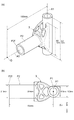
図9に示す形状をなす本実施形態の接続具1を準備した。更に比較のために、図10に示す接続具92と、図11に示す接続具93とを準備した。図10の接続具92は、第2円筒部P2の後端を第1円筒部P1の外側面に接合した構造をなす。図11の接続具93は、接続具92に加えて、第2円筒部P2の後端部に厚さ3mmの補強リブ95を放射状に8つ形成したものである。接続具1,92,93の材料として、ポリアセタール(旭化成ケミカルズ株式会社製 商品名:テナック−C3510)を用いた。
A
各接続具1,92,93に共通する寸法として、第1円筒部P1の外径を18.2mmとし、第2円筒部P2の外径を21.5mmとした。また、第1円筒部P1の長さを83mmとし、第1軸線A1から第2円筒部P2の先端面P2fまでの距離を72mmとした。第1円筒部P1及び第2円筒部P2の肉厚は3mmとした。
As dimensions common to the
図9に示すように、接続具1については、連結部3のY方向の最大幅を31mmとし、連結部3のY方向の最小幅を16.5mmとした。連結部3のうち、貫通穴10とその外側とを仕切る外壁部の肉厚は4mmとし、補強リブ5の肉厚は3mmとした。連結部3のZ方向の最大幅を60mmとした。図11に示すように、接続具93のY方向の最大幅を31mmとした。各接続具1,92,93の質量は、それぞれ、47.3g,33.5g,36.3gとなった。
As shown in FIG. 9, about the
以上のような接続具1,92,93において、それぞれ、以下の2つの試験(試験1),(試験2)を行った。試験の結果は、下表1に示す。
The following two tests (Test 1) and (Test 2) were performed on the
(試験1)図9(a)に例示するように、荷重を印加する印加点Qを第2軸線A2上に設定した。印加点Qは、第1軸線A1から100mmの距離に位置する。第1の棒体B1を固定した状態から、印加点Qに−Z方向に300Nの集中荷重を印加し、印加点Q−Z方向への最大変位量を測定し、試験後における接続具の破壊の有無を確認した。なおここでは、荷重によって接続具が塑性変形することを「破壊」とする。
(試験2)第1の棒体B1を固定した状態から、上記の印加点Qに対して軸線A2周りの30Nmの捩り荷重を印加し、第2円筒部P2の先端面P2fの最大変位量を測定し、試験後における接続具の破壊の有無を確認した。
(Test 1) As illustrated in FIG. 9A, the application point Q for applying a load was set on the second axis A2. The application point Q is located at a distance of 100 mm from the first axis A1. From a state in which the first rod B1 is fixed, a concentrated load of 300 N is applied to the application point Q in the -Z direction, the maximum displacement in the application point Q-Z direction is measured, and the connector breaks after the test. The presence or absence was confirmed. Here, “destructive” means that the connector is plastically deformed by a load.
(Test 2) From the state in which the first rod B1 is fixed, a torsional load of 30 Nm around the axis A2 is applied to the application point Q, and the maximum displacement amount of the tip surface P2f of the second cylindrical portion P2 is set. Measurements were made to confirm the presence or absence of breakage of the connector after the test.

(試験結果の考察)
接続具92,93は、試験1又は2の何れかの負荷によって破壊が生じることが判った。よって、接続具92,93を試験1及び2の負荷条件で使用するためには、各部位を肉厚にするなど、材料を増加させる必要があり、質量(重量)が増加してしまう。これに対し、接続具1は、試験1及び2において何れの負荷によっても破壊が生じず、試験1及び2の負荷条件で使用可能であることが判った。接続具1の質量は、接続具92の約1.4倍(40%増加)、接続具93の約1.3倍(約30%増加)に抑えられている。以上より、接続具1によれば、極端に質量(重量)を増加させることなく、強度を確保し易いことが確認された。
(Consideration of test results)
It was found that the
試験1による接続具92と接続具1との質量及び最大変位量を比較する。接続具1は接続具92に対して、約1.4倍の質量(40%増加)に抑えながらも、試験1による最大変位量は約1.7分の1に抑えられている。試験2による接続具92,93と接続具1との質量及び最大変位量を比較する。接続具1は接続具92に対して、約1.4倍の質量(約40%増加)に抑えながらも、試験2による最大変位量は約1.7分の1に抑えられている。また、接続具1は接続具93に対して、約1.3倍の質量(約30%増加)に抑えながらも、試験2による最大変位量は約1.6分の1に抑えられている。以上より、接続具1によれば、極端に質量(重量)を増加させることなく、剛性を確保し易いことが確認された。
The mass and maximum displacement amount of the
以上、本発明の一実施形態について説明したが、本発明は、上記実施形態に限られるものではなく、各請求項に記載した要旨を変更しない範囲で変形したものであってもよい。例えば、実施形態では、第1軸線A1と第2軸線A2とが直交しているが、本発明においては、第1の軸線と第2の軸線とは直交に限られず、互いに交差する軸線であればよい。 Although one embodiment of the present invention has been described above, the present invention is not limited to the above-described embodiment, and may be modified without changing the gist described in each claim. For example, in the embodiment, the first axis A1 and the second axis A2 are orthogonal to each other. However, in the present invention, the first axis and the second axis are not limited to orthogonal, and may be axes that intersect each other. That's fine.
1,1A,1B,1C…接続具、3…連結部、3z…連結部の幅、3ym…連結部の最大幅、5…補強リブ、10…貫通穴、11,12,13…貫通穴の領域、13…最短の線分、13s…線分の中点、103…回転軸(第1の棒体)、104…棒材(第2の棒体)、A1…第1軸線(第1の軸線)、A2…第2軸線(第2の軸線)、B1…第1棒体(第1の棒体)、B2…第2棒体(第2の棒体)、B2a…端面、B2b…外側面、P1…第1円筒部(第1の筒部)、P1b…外側面、P1c…内側面、P2…第2円筒部(第2の筒部)、P2a…端部、P2y…第2円筒部の幅。
1, 1A, 1B, 1C ... connector, 3 ... connecting portion, 3z ... width of connecting portion, 3ym ... maximum width of connecting portion, 5 ... reinforcing rib, 10 ... through hole, 11, 12, 13 ... through hole Area, 13 ... shortest line segment, 13s ... midpoint of line segment, 103 ... rotation axis (first rod), 104 ... rod (second rod), A1 ... first axis (first axis) Axis), A2 ... second axis (second axis), B1 ... first rod (first rod), B2 ... second rod (second rod), B2a ... end face, B2b ... outside Side surface, P1... First cylindrical portion (first tube portion), P1b... Outer surface, P1c... Inner surface, P2... Second cylinder portion (second tube portion), P2a. The width of the part.
Claims (7)
第1の軸線上に延在する前記第1の棒体が挿入される第1の筒部と、
前記第1の軸線に交差する第2の軸線上に延在する前記第2の棒体が、一端面を前記第1の棒体の外側面に向けた状態で挿入される第2の筒部と、
前記第1の筒部の外側面から前記第2の筒部の端部まで延び、前記第1の筒部と第2の筒部とを連結する連結部と、を備え、
前記連結部には、
前記第1の軸線の方向に貫通する貫通穴が形成されていると共に、前記貫通穴を複数の領域に仕切るように当該貫通穴の貫通方向に延び略平板状をなす補強リブが形成されており、
前記第1及び第2の軸線の双方を含む平面に投射した形状においては、
前記連結部の幅は、前記第1の筒部に近い位置ほど広く、
前記第1の軸線に直交する平面に投射した形状においては、
前記連結部の最大幅は前記第2の筒部の幅よりも大きく、前記連結部の前記最大幅が現れる位置は前記第1の筒部よりも前記第2の筒部に近く、前記補強リブは、前記貫通穴の内側面のうち前記第2の軸線が通過する位置から、前記連結部の前記最大幅が現れる部分と前記第1の筒部の内側面とを結ぶ最短の線分の略中央の位置に向けて、略直線状に延びている接続具。 A connecting tool for connecting the first rod and the second rod,
A first tube portion into which the first rod body extending on the first axis is inserted;
A second cylindrical portion in which the second rod body extending on the second axis intersecting the first axis is inserted with one end face directed to the outer surface of the first rod body When,
A connection portion extending from an outer surface of the first tube portion to an end portion of the second tube portion, and connecting the first tube portion and the second tube portion;
In the connecting part,
A through hole penetrating in the direction of the first axis is formed, and a reinforcing rib having a substantially flat plate shape is formed extending in the through direction of the through hole so as to partition the through hole into a plurality of regions. ,
In the shape projected on the plane including both the first and second axes,
The width of the connecting portion is wider as the position is closer to the first tube portion,
In the shape projected on the plane orthogonal to the first axis,
The maximum width of the connecting portion is larger than the width of the second cylindrical portion, and the position where the maximum width of the connecting portion appears is closer to the second cylindrical portion than the first cylindrical portion, and the reinforcing rib Is an abbreviation of the shortest line segment connecting the portion where the maximum width of the connecting portion appears and the inner surface of the first cylindrical portion from the position where the second axis passes through the inner surface of the through hole. A connector extending substantially in a straight line toward the center position.
前記接続具の前記第1の筒部に挿入され、外側面を前記第1の筒部の内側面に摺動させる前記第1の棒体と、を備え、
前記第1の棒体は、前記第1の筒部内で前記第1の軸周りに回転し、
前記第1の筒部の前記内側面と前記第1の棒体の前記外側面との動摩擦係数が、JISK7125試験で測定した場合に、0.5以下である駆動機構。 The connector according to any one of claims 1 to 5,
The first rod body that is inserted into the first tube portion of the connector and slides the outer surface to the inner surface of the first tube portion;
The first rod body rotates around the first axis in the first tube portion,
A drive mechanism in which a dynamic friction coefficient between the inner side surface of the first cylindrical portion and the outer side surface of the first rod is 0.5 or less when measured by a JISK7125 test.
前記接続具の前記第1の筒部に挿入され、外側面を前記第1の筒部の内側面に摺動させる前記第1の棒体と、を備え、
前記接続具は、前記第1の棒体を中心にして前記第1の軸周りに回転し、
前記第1の筒部の前記内側面と前記第1の棒体の前記外側面との動摩擦係数が、JISK7125試験で測定した場合に、0.5以下である駆動機構。 The connector according to any one of claims 1 to 5,
The first rod body that is inserted into the first tube portion of the connector and slides the outer surface to the inner surface of the first tube portion;
The connector rotates around the first axis about the first rod;
A drive mechanism in which a dynamic friction coefficient between the inner side surface of the first cylindrical portion and the outer side surface of the first rod is 0.5 or less when measured by a JISK7125 test.
Priority Applications (1)
| Application Number | Priority Date | Filing Date | Title |
|---|---|---|---|
| JP2011270265A JP5808237B2 (en) | 2011-12-09 | 2011-12-09 | Connector and drive mechanism |
Applications Claiming Priority (1)
| Application Number | Priority Date | Filing Date | Title |
|---|---|---|---|
| JP2011270265A JP5808237B2 (en) | 2011-12-09 | 2011-12-09 | Connector and drive mechanism |
Publications (3)
| Publication Number | Publication Date |
|---|---|
| JP2013122268A JP2013122268A (en) | 2013-06-20 |
| JP2013122268A5 JP2013122268A5 (en) | 2015-01-15 |
| JP5808237B2 true JP5808237B2 (en) | 2015-11-10 |
Family
ID=48774342
Family Applications (1)
| Application Number | Title | Priority Date | Filing Date |
|---|---|---|---|
| JP2011270265A Expired - Fee Related JP5808237B2 (en) | 2011-12-09 | 2011-12-09 | Connector and drive mechanism |
Country Status (1)
| Country | Link |
|---|---|
| JP (1) | JP5808237B2 (en) |
-
2011
- 2011-12-09 JP JP2011270265A patent/JP5808237B2/en not_active Expired - Fee Related
Also Published As
| Publication number | Publication date |
|---|---|
| JP2013122268A (en) | 2013-06-20 |
Similar Documents
| Publication | Publication Date | Title |
|---|---|---|
| JP5032383B2 (en) | Vehicle cooling component support device | |
| JP6112082B2 (en) | Instrument panel mounting structure | |
| JP6120048B2 (en) | Fascia coupling bracket | |
| JP2009532273A (en) | Arm for independent suspension of automobile and independent suspension for automobile having the same | |
| CN107107962B (en) | Instrument panel reinforcement | |
| US9744985B2 (en) | Rack bar unit of vehicle steering device | |
| CN103649565B (en) | Clip | |
| CN105365795B (en) | Pedal for vehicle arm | |
| JP5808237B2 (en) | Connector and drive mechanism | |
| CN103189265B (en) | Turn to supporting member | |
| CN204955975U (en) | Swing arm and car | |
| CN106275081B (en) | The support connection structure of fore sub frame and the vehicle body assemble method of fore sub frame | |
| CN113573921A (en) | Steering knuckle for vehicle | |
| CN110077450B (en) | Steering parts | |
| JP2008179258A (en) | Structure of steering support part | |
| JP5495566B2 (en) | Accelerometer and bumper cover | |
| CN103702895B (en) | There is the rack mechanism of the wheel steering system of the housing of band connecting interface | |
| JP5617657B2 (en) | Sub-frame | |
| CN115003558A (en) | support bracket | |
| CN116710347A (en) | Steering device | |
| CN103395349B (en) | Guide arm for vehicle and vehicle with same | |
| JP6719277B2 (en) | Unit frame, vehicle frame | |
| CN217917505U (en) | Suspension control arm, suspension system and vehicle | |
| JP2014065496A (en) | Sub frame | |
| CN209972579U (en) | Subframe assembly and vehicle |
Legal Events
| Date | Code | Title | Description |
|---|---|---|---|
| A521 | Request for written amendment filed |
Free format text: JAPANESE INTERMEDIATE CODE: A523 Effective date: 20141125 |
|
| A621 | Written request for application examination |
Free format text: JAPANESE INTERMEDIATE CODE: A621 Effective date: 20141125 |
|
| A977 | Report on retrieval |
Free format text: JAPANESE INTERMEDIATE CODE: A971007 Effective date: 20150807 |
|
| TRDD | Decision of grant or rejection written | ||
| A01 | Written decision to grant a patent or to grant a registration (utility model) |
Free format text: JAPANESE INTERMEDIATE CODE: A01 Effective date: 20150901 |
|
| A61 | First payment of annual fees (during grant procedure) |
Free format text: JAPANESE INTERMEDIATE CODE: A61 Effective date: 20150908 |
|
| R150 | Certificate of patent or registration of utility model |
Ref document number: 5808237 Country of ref document: JP Free format text: JAPANESE INTERMEDIATE CODE: R150 |
|
| S111 | Request for change of ownership or part of ownership |
Free format text: JAPANESE INTERMEDIATE CODE: R313111 |
|
| R350 | Written notification of registration of transfer |
Free format text: JAPANESE INTERMEDIATE CODE: R350 |
|
| S531 | Written request for registration of change of domicile |
Free format text: JAPANESE INTERMEDIATE CODE: R313531 |
|
| R350 | Written notification of registration of transfer |
Free format text: JAPANESE INTERMEDIATE CODE: R350 |
|
| LAPS | Cancellation because of no payment of annual fees |