JP5807782B2 - Exhaust gas purification catalyst - Google Patents
Exhaust gas purification catalyst Download PDFInfo
- Publication number
- JP5807782B2 JP5807782B2 JP2011288798A JP2011288798A JP5807782B2 JP 5807782 B2 JP5807782 B2 JP 5807782B2 JP 2011288798 A JP2011288798 A JP 2011288798A JP 2011288798 A JP2011288798 A JP 2011288798A JP 5807782 B2 JP5807782 B2 JP 5807782B2
- Authority
- JP
- Japan
- Prior art keywords
- upper layer
- layer
- exhaust gas
- catalyst
- lower layer
- Prior art date
- Legal status (The legal status is an assumption and is not a legal conclusion. Google has not performed a legal analysis and makes no representation as to the accuracy of the status listed.)
- Expired - Fee Related
Links
- 239000003054 catalyst Substances 0.000 title claims description 146
- 238000000746 purification Methods 0.000 title claims description 36
- 239000007789 gas Substances 0.000 claims description 88
- 239000000463 material Substances 0.000 claims description 63
- 239000002131 composite material Substances 0.000 claims description 46
- 239000000758 substrate Substances 0.000 claims description 38
- 229910052763 palladium Inorganic materials 0.000 claims description 31
- 229910052703 rhodium Inorganic materials 0.000 claims description 27
- 229910052760 oxygen Inorganic materials 0.000 claims description 24
- QVGXLLKOCUKJST-UHFFFAOYSA-N atomic oxygen Chemical compound [O] QVGXLLKOCUKJST-UHFFFAOYSA-N 0.000 claims description 23
- 239000001301 oxygen Substances 0.000 claims description 23
- 238000011144 upstream manufacturing Methods 0.000 claims description 23
- 229910000510 noble metal Inorganic materials 0.000 claims description 17
- 238000003860 storage Methods 0.000 claims description 6
- 229910021193 La 2 O 3 Inorganic materials 0.000 claims description 5
- 239000010410 layer Substances 0.000 description 266
- KDLHZDBZIXYQEI-UHFFFAOYSA-N palladium Substances [Pd] KDLHZDBZIXYQEI-UHFFFAOYSA-N 0.000 description 135
- 239000010948 rhodium Substances 0.000 description 70
- 229910018072 Al 2 O 3 Inorganic materials 0.000 description 27
- 239000002002 slurry Substances 0.000 description 27
- 239000000843 powder Substances 0.000 description 14
- 230000000694 effects Effects 0.000 description 13
- 239000000446 fuel Substances 0.000 description 13
- BASFCYQUMIYNBI-UHFFFAOYSA-N platinum Substances [Pt] BASFCYQUMIYNBI-UHFFFAOYSA-N 0.000 description 12
- 230000003197 catalytic effect Effects 0.000 description 10
- 239000004215 Carbon black (E152) Substances 0.000 description 9
- 229930195733 hydrocarbon Natural products 0.000 description 9
- 150000002430 hydrocarbons Chemical class 0.000 description 9
- 238000012360 testing method Methods 0.000 description 9
- 238000010521 absorption reaction Methods 0.000 description 8
- MCMNRKCIXSYSNV-UHFFFAOYSA-N ZrO2 Inorganic materials O=[Zr]=O MCMNRKCIXSYSNV-UHFFFAOYSA-N 0.000 description 7
- 238000005245 sintering Methods 0.000 description 7
- 238000005275 alloying Methods 0.000 description 6
- PNEYBMLMFCGWSK-UHFFFAOYSA-N aluminium oxide Inorganic materials [O-2].[O-2].[O-2].[Al+3].[Al+3] PNEYBMLMFCGWSK-UHFFFAOYSA-N 0.000 description 6
- 150000001875 compounds Chemical class 0.000 description 6
- 239000006185 dispersion Substances 0.000 description 6
- 238000000034 method Methods 0.000 description 6
- 238000002156 mixing Methods 0.000 description 6
- 229910052697 platinum Inorganic materials 0.000 description 6
- 229910052788 barium Inorganic materials 0.000 description 5
- DSAJWYNOEDNPEQ-UHFFFAOYSA-N barium atom Chemical compound [Ba] DSAJWYNOEDNPEQ-UHFFFAOYSA-N 0.000 description 5
- 239000011230 binding agent Substances 0.000 description 5
- 230000015572 biosynthetic process Effects 0.000 description 5
- 238000001035 drying Methods 0.000 description 5
- 229910052746 lanthanum Inorganic materials 0.000 description 5
- FZLIPJUXYLNCLC-UHFFFAOYSA-N lanthanum atom Chemical compound [La] FZLIPJUXYLNCLC-UHFFFAOYSA-N 0.000 description 5
- 239000010970 precious metal Substances 0.000 description 5
- 229910052761 rare earth metal Inorganic materials 0.000 description 5
- 229910001404 rare earth metal oxide Inorganic materials 0.000 description 5
- 239000000126 substance Substances 0.000 description 5
- UGFAIRIUMAVXCW-UHFFFAOYSA-N Carbon monoxide Chemical compound [O+]#[C-] UGFAIRIUMAVXCW-UHFFFAOYSA-N 0.000 description 4
- 239000007864 aqueous solution Substances 0.000 description 4
- 229910002091 carbon monoxide Inorganic materials 0.000 description 4
- CETPSERCERDGAM-UHFFFAOYSA-N ceric oxide Chemical compound O=[Ce]=O CETPSERCERDGAM-UHFFFAOYSA-N 0.000 description 4
- 229910000422 cerium(IV) oxide Inorganic materials 0.000 description 4
- 238000002485 combustion reaction Methods 0.000 description 4
- 238000000465 moulding Methods 0.000 description 4
- QTBSBXVTEAMEQO-UHFFFAOYSA-N Acetic acid Chemical compound CC(O)=O QTBSBXVTEAMEQO-UHFFFAOYSA-N 0.000 description 3
- OYPRJOBELJOOCE-UHFFFAOYSA-N Calcium Chemical compound [Ca] OYPRJOBELJOOCE-UHFFFAOYSA-N 0.000 description 3
- GRYLNZFGIOXLOG-UHFFFAOYSA-N Nitric acid Chemical compound O[N+]([O-])=O GRYLNZFGIOXLOG-UHFFFAOYSA-N 0.000 description 3
- 239000000956 alloy Substances 0.000 description 3
- 229910045601 alloy Inorganic materials 0.000 description 3
- 229910052791 calcium Inorganic materials 0.000 description 3
- 239000011575 calcium Substances 0.000 description 3
- 239000012876 carrier material Substances 0.000 description 3
- 239000011248 coating agent Substances 0.000 description 3
- 238000000576 coating method Methods 0.000 description 3
- 239000012153 distilled water Substances 0.000 description 3
- 229910052809 inorganic oxide Inorganic materials 0.000 description 3
- 239000000203 mixture Substances 0.000 description 3
- 229910017604 nitric acid Inorganic materials 0.000 description 3
- 229910052723 transition metal Inorganic materials 0.000 description 3
- XLYOFNOQVPJJNP-UHFFFAOYSA-N water Chemical compound O XLYOFNOQVPJJNP-UHFFFAOYSA-N 0.000 description 3
- 229910020203 CeO Inorganic materials 0.000 description 2
- UFHFLCQGNIYNRP-UHFFFAOYSA-N Hydrogen Chemical compound [H][H] UFHFLCQGNIYNRP-UHFFFAOYSA-N 0.000 description 2
- 229910002651 NO3 Inorganic materials 0.000 description 2
- 229910017493 Nd 2 O 3 Inorganic materials 0.000 description 2
- NHNBFGGVMKEFGY-UHFFFAOYSA-N Nitrate Chemical compound [O-][N+]([O-])=O NHNBFGGVMKEFGY-UHFFFAOYSA-N 0.000 description 2
- KJTLSVCANCCWHF-UHFFFAOYSA-N Ruthenium Chemical compound [Ru] KJTLSVCANCCWHF-UHFFFAOYSA-N 0.000 description 2
- 230000002378 acidificating effect Effects 0.000 description 2
- 239000000919 ceramic Substances 0.000 description 2
- 239000011247 coating layer Substances 0.000 description 2
- 229910052878 cordierite Inorganic materials 0.000 description 2
- JSKIRARMQDRGJZ-UHFFFAOYSA-N dimagnesium dioxido-bis[(1-oxido-3-oxo-2,4,6,8,9-pentaoxa-1,3-disila-5,7-dialuminabicyclo[3.3.1]nonan-7-yl)oxy]silane Chemical compound [Mg++].[Mg++].[O-][Si]([O-])(O[Al]1O[Al]2O[Si](=O)O[Si]([O-])(O1)O2)O[Al]1O[Al]2O[Si](=O)O[Si]([O-])(O1)O2 JSKIRARMQDRGJZ-UHFFFAOYSA-N 0.000 description 2
- 238000005516 engineering process Methods 0.000 description 2
- 238000010304 firing Methods 0.000 description 2
- 239000001257 hydrogen Substances 0.000 description 2
- 229910052739 hydrogen Inorganic materials 0.000 description 2
- 230000001771 impaired effect Effects 0.000 description 2
- 229910052741 iridium Inorganic materials 0.000 description 2
- GKOZUEZYRPOHIO-UHFFFAOYSA-N iridium atom Chemical compound [Ir] GKOZUEZYRPOHIO-UHFFFAOYSA-N 0.000 description 2
- 229910044991 metal oxide Inorganic materials 0.000 description 2
- 150000004706 metal oxides Chemical class 0.000 description 2
- 229910052762 osmium Inorganic materials 0.000 description 2
- SYQBFIAQOQZEGI-UHFFFAOYSA-N osmium atom Chemical compound [Os] SYQBFIAQOQZEGI-UHFFFAOYSA-N 0.000 description 2
- 230000003647 oxidation Effects 0.000 description 2
- 238000007254 oxidation reaction Methods 0.000 description 2
- 238000005192 partition Methods 0.000 description 2
- 231100000572 poisoning Toxicity 0.000 description 2
- 230000000607 poisoning effect Effects 0.000 description 2
- MHOVAHRLVXNVSD-UHFFFAOYSA-N rhodium atom Chemical compound [Rh] MHOVAHRLVXNVSD-UHFFFAOYSA-N 0.000 description 2
- 229910052707 ruthenium Inorganic materials 0.000 description 2
- 229920006395 saturated elastomer Polymers 0.000 description 2
- 239000006104 solid solution Substances 0.000 description 2
- 239000003381 stabilizer Substances 0.000 description 2
- 229910052779 Neodymium Inorganic materials 0.000 description 1
- 229910052777 Praseodymium Inorganic materials 0.000 description 1
- ITHZDDVSAWDQPZ-UHFFFAOYSA-L barium acetate Chemical compound [Ba+2].CC([O-])=O.CC([O-])=O ITHZDDVSAWDQPZ-UHFFFAOYSA-L 0.000 description 1
- 229910000420 cerium oxide Inorganic materials 0.000 description 1
- 238000006243 chemical reaction Methods 0.000 description 1
- 230000000593 degrading effect Effects 0.000 description 1
- 238000013461 design Methods 0.000 description 1
- 238000011161 development Methods 0.000 description 1
- 238000010586 diagram Methods 0.000 description 1
- 238000011156 evaluation Methods 0.000 description 1
- 239000006260 foam Substances 0.000 description 1
- 238000004519 manufacturing process Methods 0.000 description 1
- 238000001465 metallisation Methods 0.000 description 1
- 238000012986 modification Methods 0.000 description 1
- 230000004048 modification Effects 0.000 description 1
- TWNQGVIAIRXVLR-UHFFFAOYSA-N oxo(oxoalumanyloxy)alumane Chemical compound O=[Al]O[Al]=O TWNQGVIAIRXVLR-UHFFFAOYSA-N 0.000 description 1
- BMMGVYCKOGBVEV-UHFFFAOYSA-N oxo(oxoceriooxy)cerium Chemical compound [Ce]=O.O=[Ce]=O BMMGVYCKOGBVEV-UHFFFAOYSA-N 0.000 description 1
- RVTZCBVAJQQJTK-UHFFFAOYSA-N oxygen(2-);zirconium(4+) Chemical compound [O-2].[O-2].[Zr+4] RVTZCBVAJQQJTK-UHFFFAOYSA-N 0.000 description 1
- 150000002940 palladium Chemical class 0.000 description 1
- 239000008188 pellet Substances 0.000 description 1
- 150000003283 rhodium Chemical class 0.000 description 1
- RMAQACBXLXPBSY-UHFFFAOYSA-N silicic acid Chemical compound O[Si](O)(O)O RMAQACBXLXPBSY-UHFFFAOYSA-N 0.000 description 1
- HBMJWWWQQXIZIP-UHFFFAOYSA-N silicon carbide Chemical compound [Si+]#[C-] HBMJWWWQQXIZIP-UHFFFAOYSA-N 0.000 description 1
- 239000000243 solution Substances 0.000 description 1
- 239000010935 stainless steel Substances 0.000 description 1
- 229910001220 stainless steel Inorganic materials 0.000 description 1
- 238000000629 steam reforming Methods 0.000 description 1
- 230000001629 suppression Effects 0.000 description 1
- 229910001928 zirconium oxide Inorganic materials 0.000 description 1
Images


Classifications
-
- B—PERFORMING OPERATIONS; TRANSPORTING
- B01—PHYSICAL OR CHEMICAL PROCESSES OR APPARATUS IN GENERAL
- B01J—CHEMICAL OR PHYSICAL PROCESSES, e.g. CATALYSIS OR COLLOID CHEMISTRY; THEIR RELEVANT APPARATUS
- B01J23/00—Catalysts comprising metals or metal oxides or hydroxides, not provided for in group B01J21/00
- B01J23/38—Catalysts comprising metals or metal oxides or hydroxides, not provided for in group B01J21/00 of noble metals
- B01J23/54—Catalysts comprising metals or metal oxides or hydroxides, not provided for in group B01J21/00 of noble metals combined with metals, oxides or hydroxides provided for in groups B01J23/02 - B01J23/36
- B01J23/56—Platinum group metals
- B01J23/63—Platinum group metals with rare earths or actinides
-
- B—PERFORMING OPERATIONS; TRANSPORTING
- B01—PHYSICAL OR CHEMICAL PROCESSES OR APPARATUS IN GENERAL
- B01D—SEPARATION
- B01D53/00—Separation of gases or vapours; Recovering vapours of volatile solvents from gases; Chemical or biological purification of waste gases, e.g. engine exhaust gases, smoke, fumes, flue gases, aerosols
- B01D53/34—Chemical or biological purification of waste gases
- B01D53/92—Chemical or biological purification of waste gases of engine exhaust gases
- B01D53/94—Chemical or biological purification of waste gases of engine exhaust gases by catalytic processes
- B01D53/9445—Simultaneously removing carbon monoxide, hydrocarbons or nitrogen oxides making use of three-way catalysts [TWC] or four-way-catalysts [FWC]
- B01D53/945—Simultaneously removing carbon monoxide, hydrocarbons or nitrogen oxides making use of three-way catalysts [TWC] or four-way-catalysts [FWC] characterised by a specific catalyst
-
- B—PERFORMING OPERATIONS; TRANSPORTING
- B01—PHYSICAL OR CHEMICAL PROCESSES OR APPARATUS IN GENERAL
- B01J—CHEMICAL OR PHYSICAL PROCESSES, e.g. CATALYSIS OR COLLOID CHEMISTRY; THEIR RELEVANT APPARATUS
- B01J23/00—Catalysts comprising metals or metal oxides or hydroxides, not provided for in group B01J21/00
- B01J23/002—Mixed oxides other than spinels, e.g. perovskite
-
- B—PERFORMING OPERATIONS; TRANSPORTING
- B01—PHYSICAL OR CHEMICAL PROCESSES OR APPARATUS IN GENERAL
- B01J—CHEMICAL OR PHYSICAL PROCESSES, e.g. CATALYSIS OR COLLOID CHEMISTRY; THEIR RELEVANT APPARATUS
- B01J23/00—Catalysts comprising metals or metal oxides or hydroxides, not provided for in group B01J21/00
- B01J23/38—Catalysts comprising metals or metal oxides or hydroxides, not provided for in group B01J21/00 of noble metals
- B01J23/40—Catalysts comprising metals or metal oxides or hydroxides, not provided for in group B01J21/00 of noble metals of the platinum group metals
- B01J23/44—Palladium
-
- B—PERFORMING OPERATIONS; TRANSPORTING
- B01—PHYSICAL OR CHEMICAL PROCESSES OR APPARATUS IN GENERAL
- B01J—CHEMICAL OR PHYSICAL PROCESSES, e.g. CATALYSIS OR COLLOID CHEMISTRY; THEIR RELEVANT APPARATUS
- B01J23/00—Catalysts comprising metals or metal oxides or hydroxides, not provided for in group B01J21/00
- B01J23/38—Catalysts comprising metals or metal oxides or hydroxides, not provided for in group B01J21/00 of noble metals
- B01J23/40—Catalysts comprising metals or metal oxides or hydroxides, not provided for in group B01J21/00 of noble metals of the platinum group metals
- B01J23/46—Ruthenium, rhodium, osmium or iridium
- B01J23/464—Rhodium
-
- B—PERFORMING OPERATIONS; TRANSPORTING
- B01—PHYSICAL OR CHEMICAL PROCESSES OR APPARATUS IN GENERAL
- B01J—CHEMICAL OR PHYSICAL PROCESSES, e.g. CATALYSIS OR COLLOID CHEMISTRY; THEIR RELEVANT APPARATUS
- B01J35/00—Catalysts, in general, characterised by their form or physical properties
- B01J35/19—Catalysts containing parts with different compositions
-
- B—PERFORMING OPERATIONS; TRANSPORTING
- B01—PHYSICAL OR CHEMICAL PROCESSES OR APPARATUS IN GENERAL
- B01J—CHEMICAL OR PHYSICAL PROCESSES, e.g. CATALYSIS OR COLLOID CHEMISTRY; THEIR RELEVANT APPARATUS
- B01J37/00—Processes, in general, for preparing catalysts; Processes, in general, for activation of catalysts
- B01J37/02—Impregnation, coating or precipitation
- B01J37/0201—Impregnation
-
- B—PERFORMING OPERATIONS; TRANSPORTING
- B01—PHYSICAL OR CHEMICAL PROCESSES OR APPARATUS IN GENERAL
- B01J—CHEMICAL OR PHYSICAL PROCESSES, e.g. CATALYSIS OR COLLOID CHEMISTRY; THEIR RELEVANT APPARATUS
- B01J37/00—Processes, in general, for preparing catalysts; Processes, in general, for activation of catalysts
- B01J37/02—Impregnation, coating or precipitation
- B01J37/024—Multiple impregnation or coating
- B01J37/0244—Coatings comprising several layers
-
- B—PERFORMING OPERATIONS; TRANSPORTING
- B01—PHYSICAL OR CHEMICAL PROCESSES OR APPARATUS IN GENERAL
- B01J—CHEMICAL OR PHYSICAL PROCESSES, e.g. CATALYSIS OR COLLOID CHEMISTRY; THEIR RELEVANT APPARATUS
- B01J37/00—Processes, in general, for preparing catalysts; Processes, in general, for activation of catalysts
- B01J37/02—Impregnation, coating or precipitation
- B01J37/03—Precipitation; Co-precipitation
- B01J37/038—Precipitation; Co-precipitation to form slurries or suspensions, e.g. a washcoat
-
- B—PERFORMING OPERATIONS; TRANSPORTING
- B01—PHYSICAL OR CHEMICAL PROCESSES OR APPARATUS IN GENERAL
- B01D—SEPARATION
- B01D2255/00—Catalysts
- B01D2255/10—Noble metals or compounds thereof
- B01D2255/102—Platinum group metals
- B01D2255/1023—Palladium
-
- B—PERFORMING OPERATIONS; TRANSPORTING
- B01—PHYSICAL OR CHEMICAL PROCESSES OR APPARATUS IN GENERAL
- B01D—SEPARATION
- B01D2255/00—Catalysts
- B01D2255/10—Noble metals or compounds thereof
- B01D2255/102—Platinum group metals
- B01D2255/1025—Rhodium
-
- B—PERFORMING OPERATIONS; TRANSPORTING
- B01—PHYSICAL OR CHEMICAL PROCESSES OR APPARATUS IN GENERAL
- B01D—SEPARATION
- B01D2255/00—Catalysts
- B01D2255/20—Metals or compounds thereof
- B01D2255/206—Rare earth metals
- B01D2255/2061—Yttrium
-
- B—PERFORMING OPERATIONS; TRANSPORTING
- B01—PHYSICAL OR CHEMICAL PROCESSES OR APPARATUS IN GENERAL
- B01D—SEPARATION
- B01D2255/00—Catalysts
- B01D2255/20—Metals or compounds thereof
- B01D2255/206—Rare earth metals
- B01D2255/2065—Cerium
-
- B—PERFORMING OPERATIONS; TRANSPORTING
- B01—PHYSICAL OR CHEMICAL PROCESSES OR APPARATUS IN GENERAL
- B01D—SEPARATION
- B01D2255/00—Catalysts
- B01D2255/90—Physical characteristics of catalysts
- B01D2255/902—Multilayered catalyst
- B01D2255/9022—Two layers
-
- B—PERFORMING OPERATIONS; TRANSPORTING
- B01—PHYSICAL OR CHEMICAL PROCESSES OR APPARATUS IN GENERAL
- B01D—SEPARATION
- B01D2255/00—Catalysts
- B01D2255/90—Physical characteristics of catalysts
- B01D2255/908—O2-storage component incorporated in the catalyst
-
- B—PERFORMING OPERATIONS; TRANSPORTING
- B01—PHYSICAL OR CHEMICAL PROCESSES OR APPARATUS IN GENERAL
- B01J—CHEMICAL OR PHYSICAL PROCESSES, e.g. CATALYSIS OR COLLOID CHEMISTRY; THEIR RELEVANT APPARATUS
- B01J2523/00—Constitutive chemical elements of heterogeneous catalysts
-
- Y—GENERAL TAGGING OF NEW TECHNOLOGICAL DEVELOPMENTS; GENERAL TAGGING OF CROSS-SECTIONAL TECHNOLOGIES SPANNING OVER SEVERAL SECTIONS OF THE IPC; TECHNICAL SUBJECTS COVERED BY FORMER USPC CROSS-REFERENCE ART COLLECTIONS [XRACs] AND DIGESTS
- Y02—TECHNOLOGIES OR APPLICATIONS FOR MITIGATION OR ADAPTATION AGAINST CLIMATE CHANGE
- Y02T—CLIMATE CHANGE MITIGATION TECHNOLOGIES RELATED TO TRANSPORTATION
- Y02T10/00—Road transport of goods or passengers
- Y02T10/10—Internal combustion engine [ICE] based vehicles
- Y02T10/12—Improving ICE efficiencies
Landscapes
- Chemical & Material Sciences (AREA)
- Engineering & Computer Science (AREA)
- Materials Engineering (AREA)
- Chemical Kinetics & Catalysis (AREA)
- Organic Chemistry (AREA)
- Health & Medical Sciences (AREA)
- Combustion & Propulsion (AREA)
- Biomedical Technology (AREA)
- Environmental & Geological Engineering (AREA)
- Analytical Chemistry (AREA)
- General Chemical & Material Sciences (AREA)
- Oil, Petroleum & Natural Gas (AREA)
- Catalysts (AREA)
- Exhaust Gas Treatment By Means Of Catalyst (AREA)
Description
本発明は、内燃機関から排出される排ガスを浄化する排ガス浄化用触媒に関する。 The present invention relates to an exhaust gas purifying catalyst for purifying exhaust gas discharged from an internal combustion engine.
従来から、自動車エンジン等の内燃機関から排出される排ガスを浄化するために、Pt(白金)、Pd(パラジウム)、及びRh(ロジウム)の貴金属のうち少なくとも一種を含む三元触媒がよく用いられている(特許文献1〜3)。かかる三元触媒の一つの典型的な構成では、高耐熱性セラミックス基材の表面にアルミナからなる触媒コート層を形成し、この触媒コート層にPt、Pd、及びRhの貴金属のうち少なくとも一種を担持させている。これらの貴金属のうちPd及びPtは主として一酸化炭素(CO)及び炭化水素(HC)の浄化性能(酸化浄化能)に寄与し、Rhは主としてNOxの浄化性能(還元浄化能)に寄与する。したがって、Pd又はPtと、Rhとを併用することによって、排ガス中の有害成分を一度に効率よく浄化することができる。 Conventionally, a three-way catalyst containing at least one of noble metals of Pt (platinum), Pd (palladium), and Rh (rhodium) has been often used to purify exhaust gas discharged from an internal combustion engine such as an automobile engine. (Patent Documents 1 to 3). In one typical configuration of such a three-way catalyst, a catalyst coat layer made of alumina is formed on the surface of a high heat resistant ceramic substrate, and at least one of noble metals of Pt, Pd, and Rh is formed on the catalyst coat layer. It is supported. Among these noble metals, Pd and Pt mainly contribute to the purification performance (oxidation purification ability) of carbon monoxide (CO) and hydrocarbon (HC), and Rh mainly contributes to the purification performance (reduction purification ability) of NOx. Therefore, by using Pd or Pt and Rh in combination, harmful components in the exhaust gas can be efficiently purified at a time.
このような三元触媒を用いて効率的に排ガス中の上記成分を浄化、即ち酸化または還元によりH2O、CO2、又はN2とするためには、エンジンに供給される空気とガソリンの混合比率である空燃比が理論空燃比(ストイキ)近傍でなければならない。従来、触媒が有効に働くことができる空燃比の雰囲気変動を緩和する目的で、上記貴金属の担体としてセリア−ジルコニア複合酸化物を用いることが広く行われている。セリア−ジルコニア複合酸化物は、排ガスの空燃比がリーンであるとき(即ち酸素過剰側の雰囲気)には排ガス中の酸素を吸蔵し、排ガスの空燃比がリッチであるとき(即ち燃料過剰側の雰囲気)には吸蔵されている酸素を放出するという働きをする。これにより、排ガス中の酸素濃度が変動したときでも安定した触媒性能が得られるようになり、触媒の浄化性能が向上する。 In order to efficiently purify the above components in the exhaust gas using such a three-way catalyst, that is, to make H 2 O, CO 2 , or N 2 by oxidation or reduction, the air supplied to the engine and the gasoline The air-fuel ratio that is the mixing ratio must be close to the stoichiometric air-fuel ratio (stoichiometric). Conventionally, ceria-zirconia composite oxide has been widely used as a support for the above-mentioned noble metal for the purpose of alleviating air-fuel ratio fluctuations in which the catalyst can work effectively. The ceria-zirconia composite oxide occludes oxygen in the exhaust gas when the air-fuel ratio of the exhaust gas is lean (that is, the atmosphere on the oxygen excess side), and when the air-fuel ratio of the exhaust gas is rich (that is, on the fuel excess side). The atmosphere) works to release the stored oxygen. Thereby, even when the oxygen concentration in the exhaust gas fluctuates, stable catalyst performance can be obtained, and the purification performance of the catalyst is improved.
また、近年ではさらなる浄化性能向上のために、触媒コート層を二層構造とし、PdとRhとを分離担持させた排ガス浄化用触媒が提案されている。貴金属触媒の全てを一つの担体層に担持させるのではなく、触媒コート層を少なくとも上下二層を有する積層構造に形成し、一方の層にPdを、他方の層にRhをそれぞれ分離して担持させることにより、Rh及びPdのそれぞれに相性のよい担体を選択することが可能となる。例えばRhを担持する担体としてはZrO2が好ましい。特許文献1には、RhをZrO2に担持した上層と、PdをCeO2−ZrO2複合酸化物に担持した下層とからなる二層構造の排ガス浄化用触媒が記載されている。 In recent years, in order to further improve the purification performance, an exhaust gas purification catalyst in which the catalyst coat layer has a two-layer structure and Pd and Rh are separated and supported has been proposed. Instead of supporting all of the precious metal catalyst on one carrier layer, the catalyst coat layer is formed in a laminated structure having at least two upper and lower layers, and Pd is separated on one layer and Rh is separated on the other layer. By doing so, it becomes possible to select a carrier having good compatibility with each of Rh and Pd. For example, ZrO 2 is preferable as the carrier supporting Rh. Patent Document 1 describes an exhaust gas purification catalyst having a two-layer structure including an upper layer in which Rh is supported on ZrO 2 and a lower layer in which Pd is supported on a CeO 2 —ZrO 2 composite oxide.
上述のように、上下二層構造を有する排ガス浄化用触媒において、上層のRhを担持する担体としてはZrO2が好ましく、下層のPdを担持する担体としてはOSC能を有するCeO2−ZrO2複合酸化物が好ましいが、より高いOSC能が必要な場合は、上層のRhもCeO2−ZrO2複合酸化物に担持させる場合がある。しかし、CeO2上のRhは触媒活性がZrO2上のRhほど高くないため、RhをCeO2−ZrO2複合酸化物に担持させると、所望のNOx浄化能を発揮できない虞がある。また、近年では、製造コストの軽減や材料の安定供給を目的として、貴金属触媒の使用量を低減した低貴金属排ガス浄化用触媒の開発が進められている。しかし、かかる低貴金属排ガス浄化用触媒では、酸素吸収の仲介を担う貴金属の含有量が少ないため、OSC担体への酸素吸収効率が著しく低下してしまう。このような低貴金属化によるOSC能の低下を補うためにも、触媒全体のOSC能を効率的に向上させる技術が望まれている。 As described above, in the exhaust gas purifying catalyst having an upper and lower two-layer structure, ZrO 2 is preferable as the carrier supporting Rh in the upper layer, and CeO 2 —ZrO 2 composite having OSC ability as the carrier supporting Pd in the lower layer Although an oxide is preferable, when higher OSC ability is required, the upper layer Rh may also be supported on the CeO 2 —ZrO 2 composite oxide. However, the Rh on CeO 2 for catalytic activity is not high enough Rh on ZrO 2, when supporting the Rh in CeO 2 -ZrO 2 composite oxide, there is a possibility which can not exhibit the desired NOx purification performance. In recent years, development of a catalyst for purifying low precious metal exhaust gas in which the amount of the precious metal catalyst used is reduced has been promoted for the purpose of reducing the manufacturing cost and stably supplying the material. However, in such a low precious metal exhaust gas purification catalyst, since the content of precious metal that mediates oxygen absorption is small, the oxygen absorption efficiency to the OSC carrier is significantly reduced. In order to compensate for the decrease in OSC ability due to such low noble metalization, a technique for efficiently improving the OSC ability of the entire catalyst is desired.
本発明は、かかる事案に鑑みてなされたものであり、その主な目的は、積層構造タイプの触媒コート層を備えた排ガス浄化用触媒において、高いNOx浄化能を維持しつつ触媒全体のOSC能が効果的に高められた排ガス浄化用触媒を提供することである。 The present invention has been made in view of such a case, and a main object of the present invention is an exhaust gas purification catalyst having a laminated structure type catalyst coat layer, while maintaining a high NOx purification ability and an OSC ability of the whole catalyst. The present invention is to provide an exhaust gas purifying catalyst that is effectively enhanced.
本発明者は、OSC材に担持されたPdを下層に配置し、Rhを上層に配置した積層構造タイプの触媒コート層を備えた排ガス浄化用触媒において、下層に配置されたPdの一部を上層に移転することにより触媒全体のOSC能を向上させることに思い至り、さらに上層に配置されたPdと下層に配置されたPdとの質量比を適切に規定することによって、上層におけるRhのNOx浄化能を低下させることなく、触媒全体のOSC能を効果的に向上できることを見出し、本発明を完成した。 The inventor has arranged a part of Pd disposed in the lower layer in the exhaust gas purifying catalyst having the laminated structure type catalyst coat layer in which Pd supported on the OSC material is disposed in the lower layer and Rh is disposed in the upper layer. It was thought that the OSC ability of the whole catalyst was improved by transferring to the upper layer, and further by appropriately defining the mass ratio of Pd arranged in the upper layer and Pd arranged in the lower layer, the NOx of Rh in the upper layer The present invention was completed by finding that the OSC ability of the entire catalyst can be effectively improved without degrading the purification ability.
即ち、本発明によって提供される排ガス浄化用触媒は、基材と、該基材の表面に形成された触媒コート層とを備える排ガス浄化用触媒である。前記触媒コート層は、前記基材表面に近い方を下層とし相対的に遠い方を上層とする上下層を有する積層構造に形成されている。前記触媒コート層は、貴金属触媒としてRhとPdとを備えている。また、前記触媒コート層は、担体として酸素吸蔵能を有するOSC材を備えている。前記Rhは、前記触媒コート層の上層に配置されており、前記Pdは、前記触媒コート層の上層と下層の双方に配置されている。前記上層および下層において、前記Pdの少なくとも一部は前記OSC材に担持されている。そして、前記下層に配置されたPdに対する前記上層に配置されたPdの質量比が、0.4以下(典型的には0.01〜0.4、好ましくは0.06〜0.32)である。 That is, the exhaust gas purifying catalyst provided by the present invention is an exhaust gas purifying catalyst comprising a base material and a catalyst coat layer formed on the surface of the base material. The catalyst coat layer is formed in a laminated structure having upper and lower layers having a layer closer to the substrate surface as a lower layer and a relatively far side as an upper layer. The catalyst coat layer includes Rh and Pd as noble metal catalysts. The catalyst coat layer includes an OSC material having an oxygen storage capacity as a carrier. The Rh is disposed in the upper layer of the catalyst coat layer, and the Pd is disposed in both the upper layer and the lower layer of the catalyst coat layer. In the upper layer and the lower layer, at least a part of the Pd is supported on the OSC material. The mass ratio of Pd disposed in the upper layer to Pd disposed in the lower layer is 0.4 or less (typically 0.01 to 0.4, preferably 0.06 to 0.32). is there.
かかる構成の排ガス浄化用触媒では、OSC材に担持されたPdが上層および下層の双方に配置されている。このようにOSC材に担持されたPdを下層だけでなく、排ガスが拡散しやすい上層にも配置することにより、下層のみにPdを配置しているような従来の触媒コート層と比較して、OSC材と排ガスとの接触機会が多くなる。そのため、触媒全体のOSC能をより良く向上させることができる。 In the exhaust gas purifying catalyst having such a configuration, Pd supported on the OSC material is disposed in both the upper layer and the lower layer. In this way, by placing Pd supported on the OSC material not only on the lower layer but also on the upper layer where the exhaust gas easily diffuses, compared to a conventional catalyst coat layer in which Pd is disposed only on the lower layer, The contact opportunity between the OSC material and the exhaust gas increases. Therefore, the OSC ability of the entire catalyst can be improved better.
ここで開示される排ガス浄化用触媒としては、上層と下層とのPdの質量比(上層/下層)xが、0.01≦xを満足するものが好ましく、0.06≦xを満足するものがより好ましく、0.15≦xを満足するものがさらに好ましく、0.2≦xを満足するものが特に好ましい。その一方、上記Pdの質量比xが大きすぎると、高温時に上層でRhとPdが反応して合金化し、RhのNOx浄化能が低下する虞があるため好ましくない。RhとPdの合金化を抑制する観点からは概ねx≦0.4である。例えば0.01≦x≦0.4(好ましくは0.06≦x≦0.32)となるようなPdの質量比xで上層および下層の双方にPdを配置することが望ましい。 The exhaust gas-purifying catalyst disclosed herein preferably has an upper layer / lower layer Pd mass ratio (upper layer / lower layer) x satisfying 0.01 ≦ x and satisfying 0.06 ≦ x. Are more preferable, those satisfying 0.15 ≦ x are more preferable, and those satisfying 0.2 ≦ x are particularly preferable. On the other hand, if the mass ratio x of Pd is too large, Rh and Pd react and alloy in the upper layer at high temperatures, which is not preferable because the NOx purification ability of Rh may be reduced. From the viewpoint of suppressing alloying of Rh and Pd, x ≦ 0.4. For example, it is desirable to dispose Pd in both the upper layer and the lower layer with a mass ratio x of Pd such that 0.01 ≦ x ≦ 0.4 (preferably 0.06 ≦ x ≦ 0.32).
このことにより、下層のみにPdを配置している若しくはPdの質量比xが上記範囲を満たさないような従来の排ガス浄化用触媒と比較して、上層におけるRhの高いNOx浄化能を維持しつつ、触媒全体のOSC能を効果的に向上させることができる。したがって、本発明によると、従来に比して、NOx浄化能とOSC能とがバランスよく向上した、浄化性能に優れた最適な排ガス浄化用触媒を提供することができる。 Thus, while maintaining Pd in only the lower layer, or maintaining a high Rh NOx purification capacity in the upper layer as compared with a conventional exhaust gas purification catalyst in which the mass ratio x of Pd does not satisfy the above range. The OSC ability of the whole catalyst can be effectively improved. Therefore, according to the present invention, it is possible to provide an optimal exhaust gas purifying catalyst excellent in purifying performance in which the NOx purifying ability and the OSC ability are improved in a balanced manner as compared with the conventional art.
ここに開示される排ガス浄化用触媒の好ましい一態様では、前記上層および下層において、前記Pdの少なくとも一部を担持しているOSC材は、CeO2またはCeO2−ZrO2複合酸化物からなる。CeO2またはCeO2−ZrO2複合酸化物は高いOSC能を有しており、ここで開示される排ガス浄化用触媒に用いられるOSC材として好適である。 In a preferred aspect of the exhaust gas purifying catalyst disclosed herein, the OSC material carrying at least a part of the Pd in the upper layer and the lower layer is made of CeO 2 or CeO 2 —ZrO 2 composite oxide. CeO 2 or CeO 2 —ZrO 2 composite oxide has a high OSC ability and is suitable as an OSC material used for the exhaust gas purification catalyst disclosed herein.
ここに開示される排ガス浄化用触媒の好ましい一態様では、前記上層において、前記Rhを担持している担体は、Y2O3を含むZrO2複合酸化物からなる。ZrO2にRhを担持させることにより、高いNOx浄化能が発揮され得る。また、ZrO2にY2O3を添加することによりZrO2の耐熱性が向上し、耐久性のある排ガス浄化用触媒を得ることができる。 In a preferred aspect of the exhaust gas purifying catalyst disclosed herein, in the upper layer, the carrier supporting Rh is made of a ZrO 2 composite oxide containing Y 2 O 3 . By supporting Rh on ZrO 2 , high NOx purification ability can be exhibited. Further, it is possible to ZrO 2 Y 2 O 3 improves the heat resistance of the ZrO 2 is by adding, to obtain a catalyst for purification of exhaust gas durable.
ここに開示される排ガス浄化用触媒の好ましい一態様では、前記上層に配置されたPdに対するRhの質量比が、1.25〜5である。かかる構成によると、上層においてRhとPdとの比率が適切なバランスにあるので、RhとPdとの合金化を抑制しつつ、OSC能向上効果を確実に発揮することができる。 In a preferred embodiment of the exhaust gas-purifying catalyst disclosed herein, the mass ratio of Rh to Pd disposed in the upper layer is 1.25 to 5. According to this configuration, since the ratio of Rh and Pd is in an appropriate balance in the upper layer, the effect of improving the OSC ability can be reliably exhibited while suppressing alloying of Rh and Pd.
以下、本発明の好適な実施形態を図面に基づいて説明する。なお、本明細書において特に言及している事項以外の事柄であって本発明の実施に必要な事柄(例えば排ガス浄化用触媒の自動車における配置に関するような一般的事項)は、当該分野における従来技術に基づく当業者の設計事項として把握され得る。本発明は、本明細書に開示されている内容と当該分野における技術常識とに基づいて実施することができる。なお、以下の説明において、空燃比がリーン、ストイキおよびリッチの排ガスとは、それぞれリーン、ストイキおよびリッチの混合ガスを内燃機関にて燃焼させた際に、該内燃機関から排出される排ガスの空燃比と同等の空燃比を有する排ガスもしくは該排ガスに炭化水素を後供給した排ガスを指すものである。 DESCRIPTION OF EXEMPLARY EMBODIMENTS Hereinafter, preferred embodiments of the invention will be described with reference to the drawings. Note that matters other than the matters specifically mentioned in the present specification and necessary for the implementation of the present invention (for example, general matters relating to the arrangement of the exhaust gas purifying catalyst in an automobile) are the prior art in this field. It can be grasped as a design matter of those skilled in the art based on the above. The present invention can be carried out based on the contents disclosed in this specification and common technical knowledge in the field. In the following description, the exhaust gas having lean, stoichiometric, and rich air-fuel ratios means that the exhaust gas exhausted from the internal combustion engine when the lean, stoichiometric, and rich mixed gas is burned in the internal combustion engine, respectively. It refers to an exhaust gas having an air-fuel ratio equivalent to the fuel ratio or an exhaust gas in which hydrocarbon is post-supplied to the exhaust gas.
ここで開示される排ガス浄化用触媒は、基材と、該基材の表面に形成された多孔質担体からなる触媒コート層と、該触媒コート層の多孔質担体に担持された貴金属触媒とからなり、上記触媒コート層は積層構造に形成されている。 The exhaust gas-purifying catalyst disclosed herein includes a base material, a catalyst coat layer formed of a porous support formed on the surface of the base material, and a noble metal catalyst supported on the porous support of the catalyst coat layer. Thus, the catalyst coat layer is formed in a laminated structure.
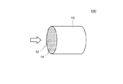
図1は排ガス浄化用触媒の一典型例の模式図である。本実施形態に係る排ガス浄化用触媒100は、複数の規則的に配列されたセル12と、該セル12を構成するリブ壁14を有するハニカム基材10を備える。なお、本明細書において「基材の体積1リットル当たり」とは、基材の純体積にセル通路の容積も含めた全体の嵩容積1L当たりをいう。以下の説明において(g/L)と記載しているものについては、基材の体積1リットルに含まれる量を示すものである。
FIG. 1 is a schematic view of a typical example of an exhaust gas purifying catalyst. The exhaust
ここで開示される排ガス浄化用触媒を構成する上記基材としては、従来のこの種の用途に用いられる種々の素材及び形態のものが使用可能である。例えば、コージェライト、炭化ケイ素(SiC)等のセラミックスまたは合金(ステンレス等)から形成されたハニカム構造を備えるハニカム基材などを好適に採用することができる。一例として外形が円筒形状であるハニカム基材であって、その筒軸方向に排ガス通路としての貫通孔(セル)が設けられ、各セルを仕切る隔壁(リブ壁)に排ガスが接触可能となっているものが挙げられる。基材の形状はハニカム形状の他にフォーム形状、ペレット形状などとすることができる。また基材全体の外形については、円筒形に代えて、楕円筒形、多角筒形を採用してもよい。 As the base material constituting the exhaust gas purifying catalyst disclosed herein, various materials and forms used for this kind of conventional applications can be used. For example, a honeycomb substrate having a honeycomb structure formed of a cordierite, ceramics such as silicon carbide (SiC), or an alloy (such as stainless steel) can be suitably used. As an example, a honeycomb base material having a cylindrical outer shape is provided with through holes (cells) as exhaust gas passages in the cylinder axis direction so that exhaust gas can contact partition walls (rib walls) that partition each cell. The thing that is. The shape of the substrate may be a foam shape, a pellet shape, etc. in addition to the honeycomb shape. Moreover, about the external shape of the whole base material, it may replace with a cylindrical shape and an elliptical cylindrical shape and a polygonal cylindrical shape may be employ | adopted.
<触媒コート層>
図2は、図1のハニカム基材10におけるリブ壁14の表面部分の構成を模式的に示す図である。リブ壁14は、基材10と、その表面に形成された二層構造の触媒コート層30を備えている。かかる二層構造の触媒コート層30は、基材10の表面に近い方を下層50とし相対的に遠い方を上層40とする上下層を有する積層構造に形成されている。ここに開示される技術では、触媒コート層30は、貴金属触媒として、RhとPdとを備えている。また、触媒コート層30は、担体として酸素吸蔵能を有するOSC材を備えている。Rhは、触媒コート層30の上層40に配置されており、Pdは、触媒コート層30の上層40と下層50の双方に配置されている。上層40および下層50において、Pdの少なくとも一部はOSC材に担持されている。
<Catalyst coat layer>
FIG. 2 is a diagram schematically showing the configuration of the surface portion of the
本発明によって提供される触媒コート層30では、OSC材に担持されたPdを下層50だけでなく、排ガスが拡散しやすい上層40にも配置する。このことにより、下層50のみにPdを配置しているような従来の触媒コート層と比較して、OSC材と排ガスとの接触機会が多くなる。そのため、触媒全体のOSC能がより良く向上させることができる。下層50に配置されたPdに対する上層40に配置されたPdの質量比(上層/下層)xとしては、0.01≦xを満足するものが好ましく、0.06≦xを満足するものがより好ましく、0.15≦xを満足するものがさらに好ましく、0.2≦xを満足するものが特に好ましい。Pdの質量比(上層/下層)が小さすぎると、上述したOSC能向上効果が不十分になることがある。
In the
その一方、上記Pdの質量比(上層/下層)xが大きすぎると、上層40において高温時にRhとPdとが部分的に反応して合金化し、RhのNOx浄化能が低下する虞があるため好ましくない。RhとPdとの合金化を抑制する観点からは、x≦0.4(例えばx≦0.32、特にはx≦0.25)を満足するものが好ましい。例えば、上記Pdの質量比(上層/下層)が、0.06以上0.32以下(特に0.15以上0.3以下)の触媒コート層30が、OSC能の向上と、Rh及びPdの合金化の抑制を両立するという観点から適当である。
On the other hand, if the Pd mass ratio (upper layer / lower layer) x is too large, Rh and Pd may partially react and alloy in the
<下層>
ここで開示される触媒コート層30を構成する下層50は、担体と、該担体に担持されている少なくともPdを含む貴金属触媒とを備えている。Pdは、主として排ガス中のHC及びCOを浄化する。
<Lower layer>
The
<下層の担体>
下層50のPdを担持する担体は、酸素吸蔵能を有するOSC材を含んでいる。かかるOSC材は、排ガスの空燃比がリーンであるとき(即ち酸素過剰側の雰囲気)には排ガス中の酸素を吸蔵し、排ガスの空燃比がリッチであるとき(即ち燃料過剰側の雰囲気)には吸蔵されている酸素を放出するという働きをする。かかるOSC材としては、例えば、酸化セリウム(セリア:CeO2)や該セリアを含む複合酸化物(例えば、セリア−ジルコニア複合酸化物(CeO2−ZrO2複合酸化物)などが挙げられる。CeO2またはCeO2−ZrO2複合酸化物を下層のPdの担体として使用することにより、下層の酸素濃度の変動が緩和され、安定した触媒性能が得られるようになる。したがって、より良好な触媒性能を確実に発揮することができる。
<Lower layer carrier>
The carrier supporting Pd of the
上述したOSC材の中でも、CeO2−ZrO2複合酸化物の使用が好ましい。CeO2にZrO2を固溶させることにより、CeO2の粒成長が抑制され、耐久後のOSC能の低下を抑制することができる。CeO2−ZrO2複合酸化物におけるCeO2とZrO2との混合割合は、CeO2/ZrO2=0.25〜0.75(好ましくは0.3〜0.6、より好ましくは0.5程度)であるとよい。CeO2/ZrO2を上記範囲にすると、Pdを含む下層50において高い触媒活性とOSC(酸素吸蔵能)を実現することができる。
Among the OSC materials described above, CeO 2 —ZrO 2 composite oxide is preferably used. By solid solution of ZrO 2 in CeO 2, grain growth of CeO 2 is suppressed, it is possible to suppress the reduction of the OSC capacity after durability. The mixing ratio of the CeO 2 and ZrO 2 in the CeO 2 -ZrO 2 composite oxide, CeO 2 / ZrO 2 = 0.25 to 0.75 (preferably 0.3 to 0.6, more preferably 0.5 Degree). When CeO 2 / ZrO 2 is in the above range, high catalytic activity and OSC (oxygen storage capacity) can be realized in the
上記CeO2−ZrO2複合酸化物は、副成分として他の化合物(典型的には無機酸化物)が混在するものであってもよい。そのような化合物としては、ランタン等の希土類元素、カルシウムなどのアルカリ土類元素、遷移金属元素などが用いられ得る。上記の中で、触媒機能を阻害せずに高温における比表面積を向上させる観点から、安定化剤としてはランタン等の希土類元素が好適に用いられる。例えば、焼結抑制等の目的で、La2O3、Y2O3、Pr6O11などの希土類酸化物を混合してもよい。上記希土類酸化物は単独酸化物として担体粉末に物理混合してもよいし、複合酸化物の一成分とすることもできる。これら副成分の含有割合(質量比)が担体全体の2%〜30%(例えば3%〜6%)であることが好ましい。副成分の含有割合が少なすぎると焼結抑制等の効果が低く、多すぎると相対的に担体中のZrO2やCeO2の量が減るため耐熱性及びOSCが低下する場合がある。 The CeO 2 —ZrO 2 composite oxide may be a mixture of other compounds (typically inorganic oxides) as subcomponents. As such a compound, a rare earth element such as lanthanum, an alkaline earth element such as calcium, a transition metal element, or the like can be used. Among these, rare earth elements such as lanthanum are preferably used as the stabilizer from the viewpoint of improving the specific surface area at high temperature without impairing the catalytic function. For example, a rare earth oxide such as La 2 O 3 , Y 2 O 3 , or Pr 6 O 11 may be mixed for the purpose of suppressing sintering. The rare earth oxide may be physically mixed with the carrier powder as a single oxide, or may be a component of a composite oxide. The content ratio (mass ratio) of these subcomponents is preferably 2% to 30% (for example, 3% to 6%) of the entire carrier. If the content ratio of the subcomponent is too small, the effect of suppressing the sintering is low, and if it is too large, the amount of ZrO 2 or CeO 2 in the support is relatively reduced, so that the heat resistance and OSC may be lowered.
ここで開示される下層50のPdを担持する担体は、OSC材以外の担体材料(非OSC材)が含まれていてもよい。かかる非OSC材としては、多孔質であり、且つ、耐熱性に優れた金属酸化物が好ましく用いられる。例えば、酸化アルミニウム(アルミナ:Al2O3)、酸化ジルコニウム(ジルコニア:ZrO2)等が挙げられる。中でもAl2O3の使用が好ましい。Al2O3は、CeO2−ZrO2複合酸化物に比べて比表面積が小さく、かつ耐久性(特に耐熱性)が高い。そのため、Al2O3にPdを担持させることにより、担体全体としての熱安定性が向上するとともに、担体全体に適量のPdを担持させることができる。Al2O3とCeO2−ZrO2複合酸化物とは、質量混合比(Al2O3:CeO2−ZrO2複合酸化物)が80:20〜20:80の範囲内で混合することが好ましい。かかる構成によると、Al2O3とCeO2−ZrO2複合酸化物との比率が適切なバランスにあるので、Al2O3とCeO2−ZrO2複合酸化物とを混合することによる効果(例えば、Al2O3が持つ大きな比表面積及び高い耐久性と、CeO2−ZrO2複合酸化物が持つ酸素吸蔵放出能を合わせ持つことができる効果)をより良く発揮することができる。
The carrier supporting Pd of the
ここで開示される下層50のPdを担持する担体には、バリウム(Ba)が添加されてもよい。下層の担体にBaを添加することにより、PdのHC被毒が抑えられ、触媒活性(特に低温活性)の向上が図られる。また、担体に対するPdの分散性が向上し、高温におけるPdの粒成長にともなうシンタリングがより良く抑えられる。ここで開示される担体としては、上記Baの添加量が、担体の全質量に対して5質量%〜10質量%を満足するものが好ましく、5質量%〜8質量%を満足するものが特に好ましい。Baの含有量を上記範囲内とすることにより、PdのHC被毒がより良く抑制され、エンジン始動直後でも高い触媒活性を発揮することができる。また、Pdのシンタリングがより良く抑制され、Pdの耐久性向上が図られる。Baの含有量が10質量%より多すぎる、または5質量%より少なすぎる場合は、上述したBa添加による触媒性能向上効果が十分に発揮されず、高い浄化性能が得られないことがある。
Barium (Ba) may be added to the carrier supporting Pd of the
<下層の貴金属触媒>
ここに開示される下層50に含有されるPd(パラジウム)は、上述したOSC材を含む担体に担持されている。Pdの担持量は特に制限されないが、下層50担体の全質量に対して0.01質量%〜1質量%の範囲(例えば0.05質量%〜0.5質量%)とすることが適当である。これより少ないと十分な触媒活性が得られず、これより多く担持させても効果が飽和するとともにコスト面で不利である。下層50の担体にPdを担持させる方法としては特に制限されない。例えば、OSC材を含む担体粉末を、パラジウム塩(例えば硝酸塩)やパラジウム錯体(例えば、テトラアンミン錯体)を含有する水溶液に含浸させた後、乾燥させ、焼成することにより調製することができる。
<Lower noble metal catalyst>
Pd (palladium) contained in the
ここで開示される下層50は、Pdの性能を損なわない程度に他の貴金属触媒を含んでいてもよい。Pd以外の貴金属触媒として、例えば、白金(Pt)、ルテニウム(Ru)、イリジウム(Ir)、オスミウム(Os)等が挙げられる。
The
下層50の成形量(コート量)は特に制限されないが、例えば、ハニカム基材10の体積1リットル当たり、40g〜200g程度であることが好ましい。下層50の成形量が少なすぎる場合は、触媒コート層としての機能が弱く担持されているPdの粒成長を招く虞がある。また、下層50の成形量が多すぎると、ハニカム基材10のセル内を排気ガスが通過する際の圧力損失の上昇を招く虞がある。
Although the molding amount (coat amount) of the
<上層>
ここで開示される触媒コート層30を構成する上層40は、担体と、該担体に担持されている少なくともRh及びPdを含む貴金属触媒とを備えている。Rhは、主として排ガス中のNOxを浄化する。
<Upper layer>
The
<上層の担体>
上層40のRhを担持する担体は、ジルコニア(ZrO2)、アルミナ(Al2O3)、これらの固溶体または複合酸化物など、従来この種の担体として用いられている物質を含有することができる。例えば、ZrO2を含む担体であることが好ましい。ZrO2に担持されたRhは、排ガス中のHCから水素改質反応によって水素を発生させる。この水素の還元力によって排ガス中のNOxがより良く浄化される。上層40のRhを担持する担体には、セリア(CeO2)が含まれていないことが好ましい。
<Upper carrier>
The carrier carrying Rh of the
上層40のRhを担持する担体は、Y2O3を含むZrO2複合酸化物であることが好ましい。ZrO2にY2O3を含有させることにより、ZrO2の耐熱性が向上し、高温耐久後の浄化性能の低下を抑制することができる。Y2O3の含有量は、Y2O3を含むZrO2複合酸化物の全質量に対して概ね5質量%〜20質量%が適当であり、好ましくは6質量%〜10質量%である。Y2O3の含有量を上記範囲にすると、Rhを含む上層40において高い触媒活性と高温耐久性を実現することができる。
The carrier supporting Rh of the
上記ZrO2複合酸化物は、副成分として他の化合物(典型的には無機酸化物)が混在するものであってもよい。そのような化合物としては、ランタン等の希土類元素、カルシウムなどのアルカリ土類元素、遷移金属元素などが用いられ得る。上記の中で、触媒機能を阻害せずに高温における比表面積を向上させる観点から、安定化剤としてはランタン等の希土類元素が好適に用いられる。例えば、焼結抑制等の目的で、La2O3、Nd2O3などの希土類酸化物を混合してもよい。上記希土類酸化物は単独酸化物として担体粉末に物理混合してもよいし、複合酸化物の一成分とすることもできる。これら副成分の含有割合(質量比)が担体全体の2質量%〜30質量%(例えば5質量%〜15質量%)であることが好ましい。副成分の含有割合が2質量%より少なすぎると焼結抑制等の効果が低く、30質量%より多すぎると相対的に担体中のZrO2の量が減るため触媒活性が低下する場合がある。 The ZrO 2 composite oxide may be a mixture of other compounds (typically inorganic oxides) as subcomponents. As such a compound, a rare earth element such as lanthanum, an alkaline earth element such as calcium, a transition metal element, or the like can be used. Among these, rare earth elements such as lanthanum are preferably used as the stabilizer from the viewpoint of improving the specific surface area at high temperature without impairing the catalytic function. For example, rare earth oxides such as La 2 O 3 and Nd 2 O 3 may be mixed for the purpose of suppressing sintering. The rare earth oxide may be physically mixed with the carrier powder as a single oxide, or may be a component of a composite oxide. The content ratio (mass ratio) of these subcomponents is preferably 2% by mass to 30% by mass (for example, 5% by mass to 15% by mass) of the entire carrier. If the content ratio of the subcomponent is less than 2% by mass, the effect of suppressing the sintering is low, and if it is more than 30% by mass, the amount of ZrO 2 in the carrier is relatively reduced, and the catalytic activity may be lowered. .
ここで開示される上層40のRhを担持する担体は、ZrO2複合酸化物以外の担体材料が含まれていてもよい。かかる担体材料としては、多孔質であり、且つ、耐熱性に優れた金属酸化物が好ましく用いられる。例えば、Al2O3の使用が好ましい。Al2O3は、ZrO2複合酸化物に比べて比表面積が小さく、かつ耐久性(特に耐熱性)が高い。そのため、Al2O3にRhを担持させることにより、担体全体としての熱安定性が向上するとともに、担体全体に適量のRhを担持させることができる。Al2O3とZrO2複合酸化物とは、質量混合比(Al2O3:ZrO2複合酸化物)が80:20〜20:80の範囲内で混合することが好ましい。
The carrier for supporting Rh of the
<上層の貴金属触媒>
ここに開示される上層40に含有されるRhは、上述したZrO2複合酸化物を含む担体に担持されている。Rhの担持量は特に制限されないが、上層のRhを担持する担体の全質量に対して0.01質量%〜1質量%の範囲(例えば0.05質量%〜0.5質量%)とすることが適当である。これより少ないと十分な触媒活性が得られず、これより多く担持させても効果が飽和するとともにコスト面で不利である。上層40の上記担体にRhを担持させる方法としては特に制限されない。例えば、ZrO2複合酸化物からなる担体粉末を、ロジウム塩(例えば硝酸塩)やロジウム錯体(例えば、テトラアンミン錯体)を含有する水溶液に含浸させた後、乾燥させ、焼成することにより調製することができる。
<Upper layer noble metal catalyst>
Rh contained in the
ここで開示される触媒コート層30の上層40は、前述のように、RhのほかにPdを含有している。上層40のPdを担持する担体としては、前記下層50のPdを担持する担体と同じものを用いることができ、CeO2−ZrO2複合酸化物等のOSC材を含む担体である。このうち、特に好適なものについては、前記下層50のPdの担体と同等であるため、その詳細な説明は省略する。
As described above, the
上層40に含まれるRhとPdとの質量比(Rh/Pd)としては、概ね1.25〜5の範囲内が適当であり、好ましくは1.25〜4であり、さらに好ましくは1.25〜3であり、特に好ましくは1.25〜2である。かかる構成によると、上層40においてRhとPdとの比率が適切なバランスにあるので、RhとPdとの合金化を抑制しつつ、OSC能向上効果を確実に発揮することができる。Pdの割合が多すぎると、RhとPdとの合金化によりRhの十分なNOx浄化効果が得られないことがあり、一方、Pdの割合が多すぎると、上述したOSC能向上効果が不十分となることがある。
The mass ratio (Rh / Pd) between Rh and Pd contained in the
ここで開示される上層40は、Rh及びPdの性能を損なわない程度に他の貴金属触媒を含んでいてもよい。Rh及びPd以外の貴金属触媒として、例えば、白金(Pt)、ルテニウム(Ru)、イリジウム(Ir)、オスミウム(Os)等が挙げられる。
The
上層40の成形量(コート量)は特に制限されないが、例えば、ハニカム基材10の体積1リットル当たり、20g〜200g程度であることが好ましい。上層40の成形量が20gよりも少なすぎる場合は、触媒コート層としての機能が弱く担持されているRh及びPdの粒成長を招く虞がある。また、上層40の成形量が200gを超えると、ハニカム基材10のセル内を排気ガスが通過する際の圧力損失の上昇を招く虞がある。
Although the molding amount (coating amount) of the
<触媒コート層の形成方法>
触媒コート層30の下層50を形成するにあたっては、担体粉末を含むスラリーを基材(例えばハニカム基材)10の表面にウォッシュコートし、それにPdを担持させてもよいし、担体粉末に予めPdを担持した触媒粉末を含むスラリーを基材10の表面にウォッシュコートしてもよい。触媒コート層30の上層40を形成するにあたっては、Rhを予め担持した担体粉末と、Pdを予め担持した担体粉末とを混合したスラリーを調製し、このスラリーを下層50の表面にウォッシュコートするとよい。
<Method for forming catalyst coat layer>
In forming the
触媒コート層30をウォッシュコートにより形成するプロセスにおいて、基材10の表面、あるいは下層50の表面にスラリーを適当に密着させるため、スラリーにはバインダーを含有させることが好ましい。バインダーとしては、例えばアルミナゾル、シリカゾル等の使用が好ましい。スラリーの粘度は、該スラリーが基材(例えばハニカム基材)のセル内へ容易に流入し得るように適宜調整するとよい。基材10の表面にウォッシュコートされたスラリーの乾燥条件は基材または担体の形状及び寸法により左右されるが、典型的には80℃〜120℃程度(例えば100℃〜110℃)で1時間〜10時間程度であり、焼成条件は約400℃〜1000℃程度(例えば500℃〜700℃)で約2時間〜4時間程度である。
In the process of forming the
なお、触媒コート層30の積層構造は、上層40として上述したようなRh及びPdを含む触媒層があり、下層50として上述したようなPdを含む触媒層があればよく、当該二つの層に加えて他の層(例えば基材に近接した別の層)を有する3層以上であってもよい。さらに、触媒コート層30は、上層40と下層50とが基材(例えばハニカム基材)10の全域にわたって上下二層構造になっている必要はなく、上層40の一部と下層50の一部とが部分的に積層されたものでもよい。例えば、図3に示すように、一方の層の端部が他方の層の端部からはみ出すように上層40と下層50とを積層してもよい。図3の例では、排ガスの流通方向において、上層40の下流側の端部40Aが下層50の下流側の端部50Aからはみ出すように積層されている。また、下層50の上流側の端部50Bが上層40の上流側の端部40Bからはみ出すように積層されている。上層40と下層50とは、基材10の全域の50%を上回る(例えば70%〜80%又はそれ以上)領域(範囲)において上下二層構造を形成していることが好ましい。
The laminated structure of the
図3に示した例では、下層50のはみ出し部分52の表面であって上層40の上流側には、前段上層60が形成されている。この実施形態では、前段上層60は、担体と、該担体に担持されている少なくともPdを含む貴金属触媒とを備えている。このように、上層40の上流側にPdを担持する前段上層60を設けることにより、排ガス中の有害物質(特にHC)を効率よく浄化することができる。すなわち、前段上層60は、HCが拡散しやすい上側(表面側)であって、しかも高温になりやすい基材10の上流側に配置されているので、Pdと排ガスとの接触機会が多くなり、また高温下において高効率で排ガスを浄化することができる。
In the example shown in FIG. 3, a front
前段上層60のPdを担持する担体は、OSC材を含んでいることが好ましい。この実施形態では、前段上層60のPdを担持する担体は、CeO2−ZrO2複合酸化物を含んでいる。CeO2−ZrO2複合酸化物は、副成分として他の化合物(典型的には無機酸化物)が混在するものであってもよい。そのような化合物としては、ランタン等の希土類元素、カルシウムなどのアルカリ土類元素、遷移金属元素などが用いられ得る。例えば、焼結抑制等の目的で、La2O3、Y2O3、Pr6O11などの希土類酸化物を混合してもよい。また、前段上層60のPdを担持する担体は、Al2O3を含んでいてもよい。さらに、前段上層60のPdを担持する担体には、バリウム(Ba)が添加されてもよい。
The carrier for supporting Pd of the upper
前段上層60は、基材10の上流側の端部10Bから下流側に向かって基材10の全長の10%〜40%(例えば15%〜25%)に当たる部分に形成されていることが好ましい。下層50は、基材10の上流側の端部10Bから下流側に向かって基材10の全長の70%〜100%(例えば85%〜95%)に当たる部分に形成されていることが好ましい。上層40は、基材10の下流側の端部10Aから上流側に向かって基材10の全長の70%〜100%(例えば75%〜85%)に当たる部分に形成されていることが好ましい。
The upstream
以下、本発明に関するいくつかの実施例につき説明するが、本発明をかかる具体例に示
すものに限定することを意図したものではない。
Several examples relating to the present invention will be described below, but the present invention is not intended to be limited to those shown in the specific examples.
本例の排ガス浄化用触媒は、図1に示すように、複数の規則的に配列されたセル12と、該セル12を構成するリブ壁14を有するハニカム基材10を備える。ハニカム基材10は、長さ105mm、容積0.875Lの円筒体であり、コージェライト製である。セル12を構成するリブ壁14の表面には、図3に示すように、触媒コート層30が形成されており、その表面の空間部にガス流路が形成されている。触媒コート層30は、下層50と、上層40と、前段上層60とから構成されている。
As shown in FIG. 1, the exhaust gas purifying catalyst of this example includes a
下層50は、Pdと、Al2O3と、CeO2−ZrO2複合酸化物と、バリウムとを含んでいる。上層40は、Rhと、Pdと、Al2O3と、ZrO2複合酸化物とを含んでいる。前段上層60は、Pdと、Al2O3と、CeO2−ZrO2複合酸化物と、バリウムとを含んでいる。
The
前段上層60は、図1及び図3に示すように、ハニカム基材の上流側の端部から下流側に向かってハニカム基材の全長の20%に当たる部分に形成されている。下層50は、ハニカム基材の上流側の端部から下流側に向かってハニカム基材の全長の90%に当たる部分に形成されている。上層40は、ハニカム基材の下流側の端部から上流側に向かってハニカム基材の全長の80%に当たる部分に形成されている。
As shown in FIGS. 1 and 3, the upstream
次に、本例の排ガス浄化用触媒の形成方法について説明する。 Next, a method for forming the exhaust gas purifying catalyst of this example will be described.
<例1>
例1では、Rhを上層に配置し、Pdを下層のみに配置した排ガス浄化用触媒を作製した。
<Example 1>
In Example 1, an exhaust gas purification catalyst in which Rh was disposed in the upper layer and Pd was disposed only in the lower layer was produced.
(1)下層の形成
0.82g/LのPdを含む硝酸系Pd薬液に、75g/Lのアルミナ(Al2O3)粉末を懸濁させて分散液を調製した。そして、該分散液に、OSC材であるCeO2−ZrO2複合酸化物の粉末(ZrO2:80wt%、Y2O3:8wt%、Nd2O3:12wt%)と、5wt%の酢酸バリウムと、5wt%のAl2O3バインダーと、蒸留水とを混合して、スラリーを得た。このスラリーを120℃の温度条件下で30分乾燥させ、更に500℃の温度条件下で2時間焼成することによって下層用触媒材料を得た。
次に、上記下層用触媒材料を酸性水溶液に分散させ、下層形成用スラリー(A)を調製した。この下層形成用スラリー(A)を用いて、ハニカム基材の上流側の一端から全長の90%に当たる部分にウォッシュコートを施し、乾燥、焼成することによって基材の表面に下層50を形成した。
(1) Formation of Lower Layer A dispersion was prepared by suspending 75 g / L of alumina (Al 2 O 3 ) powder in a nitric acid-based Pd chemical containing 0.82 g / L of Pd. In addition, CeO 2 —ZrO 2 composite oxide powder (ZrO 2 : 80 wt%, Y 2 O 3 : 8 wt%, Nd 2 O 3 : 12 wt%), which is an OSC material, and 5 wt% acetic acid were added to the dispersion. Barium, 5 wt% Al 2 O 3 binder, and distilled water were mixed to obtain a slurry. The slurry was dried at 120 ° C. for 30 minutes, and further calcined at 500 ° C. for 2 hours to obtain a lower layer catalyst material.
Next, the lower layer catalyst material was dispersed in an acidic aqueous solution to prepare a lower layer forming slurry (A). Using this lower layer forming slurry (A), a wash coat was applied to a portion corresponding to 90% of the total length from one end on the upstream side of the honeycomb substrate, and the
(2)上層の形成
0.2g/LのRhを含む硝酸系Rh薬液に、65g/LのZrO2複合酸化物の粉末(ZrO2:80wt%、Y2O3:8wt%、Nd2O3:12wt%)を懸濁させて分散液を調製した。そして、該分散液に、25g/LのAl2O3粉末と、5wt%のAl2O3バインダーと、蒸留水とを混合して、上層形成用スラリー(B)を調製した。この上層形成用スラリー(B)を用いて、ハニカム基材10の下流側の他端(下層を形成した方の端部とは逆の端部)から全長の80%に当たる部分にウォッシュコートを施し、乾燥、焼成することによって基材の表面に上層40を形成した。
(2) Formation of upper layer A 65 g / L ZrO 2 composite oxide powder (ZrO 2 : 80 wt%, Y 2 O 3 : 8 wt%, Nd 2 O was added to a nitric acid-based Rh chemical solution containing 0.2 g / L Rh. 3 : 12 wt%) was suspended to prepare a dispersion. Then, the dispersion, and Al 2 O 3 powder of 25 g / L, and 5 wt% of Al 2 O 3 binder, were mixed with distilled water to prepare a slurry for the upper layer forming (B). Using this upper layer forming slurry (B), a wash coat is applied to the portion corresponding to 80% of the total length from the other end on the downstream side of the honeycomb substrate 10 (the end opposite to the end on which the lower layer is formed). The
(3)前段上層の形成
1.0g/LのPdを含む硝酸系Pd薬液に、50g/Lのアルミナ(Al2O3)粉末を懸濁させて分散液を調製した。そして、該分散液に、OSC材であるCeO2−ZrO2複合酸化物の粉末(CeO2:60wt%、ZrO2:30wt%、La2O3:3wt%、Pr6O11:7wt%)と、5wt%の酢酸バリウムと、5wt%のAl2O3バインダーと、蒸留水とを混合して、スラリーを得た。このスラリーを120℃の温度条件下で30分乾燥させ、更に500℃の温度条件下で2時間焼成することによって前段上層用の触媒材料を得た。
次に、上記前段上層用の触媒材料を酸性水溶液に分散させ、前段上層形成用スラリー(C)を調製した。この前段上層形成用スラリー(C)を用いて、ハニカム基材の上流側の一端から全長の20%に当たる部分にウォッシュコートを施し、乾燥、焼成することによって基材の表面に前段上層60を形成した。
(3) Formation of an upper layer in the previous stage A dispersion was prepared by suspending 50 g / L of alumina (Al 2 O 3 ) powder in a nitric acid-based Pd chemical containing 1.0 g / L of Pd. In addition, CeO 2 —ZrO 2 composite oxide powder (CeO 2 : 60 wt%, ZrO 2 : 30 wt%, La 2 O 3 : 3 wt%, Pr 6 O 11 : 7 wt%) that is an OSC material is added to the dispersion. If, to obtain a 5 wt% of barium acetate, and 5 wt% of Al 2 O 3 binder, were mixed with distilled water, the slurry. This slurry was dried at 120 ° C. for 30 minutes and further calcined at 500 ° C. for 2 hours to obtain a catalyst material for the upper layer of the previous stage.
Next, the catalyst material for the upper upper layer was dispersed in an acidic aqueous solution to prepare a slurry for forming the upper upper layer (C). Using this upstream slurry for forming the upper layer (C), a portion corresponding to 20% of the entire length from one end on the upstream side of the honeycomb substrate is subjected to wash coating, and dried and fired to form the
<例2〜例5>
例2〜例5では、Rhを上層に配置し、Pdを上層および下層の双方に配置した排ガス浄化用触媒を作製した。具体的には、前述した下層形成用スラリー(A)から所量の下層用触媒材料を差し引き、その分、同量の下層用触媒材料を上層形成用スラリー(B)に混合した。前段上層形成用スラリー(C)は例1と同様に調製した。そして、上記の3種のスラリー(A)、(B)、(C)を例1と同様に基材にウォッシュコートし、乾燥、焼成することによって排ガス浄化用触媒を作製した。ここでは例2〜例5の順に、上層全体に含まれるPd量がそれぞれ0.04g、0.08g、0.16g、0.24gとなるように調整した。また、触媒全体に含まれるPd量は、0.65gで一定とした。
<Example 2 to Example 5>
In Examples 2 to 5, exhaust gas purification catalysts were prepared in which Rh was disposed in the upper layer and Pd was disposed in both the upper layer and the lower layer. Specifically, a predetermined amount of the lower layer catalyst material was subtracted from the above-described lower layer formation slurry (A), and the same amount of the lower layer catalyst material was mixed with the upper layer formation slurry (B). The slurry for forming the upper stage upper layer (C) was prepared in the same manner as in Example 1. Then, the above three types of slurries (A), (B), and (C) were wash-coated on the substrate in the same manner as in Example 1, dried and fired to produce an exhaust gas purifying catalyst. Here, in the order of Example 2 to Example 5, the amount of Pd contained in the entire upper layer was adjusted to 0.04 g, 0.08 g, 0.16 g, and 0.24 g, respectively. The amount of Pd contained in the entire catalyst was fixed at 0.65 g.
<例6>
例6では、Rhを上層に配置し、Pdを上層および下層の双方に配置した排ガス浄化用触媒を作製した。ただし、本例では上層のPdを担体に担持させずに配置した。具体的には、前述した下層形成用スラリー(A)から所量のPd(担体なし)を差し引き、その分、同量のPd(担体なし)を上層形成用スラリー(B)に混合した。前段上層形成用スラリー(C)は例1と同様に調製した。そして、上記の3種のスラリー(A)、(B)、(C)を例1と同様に基材にウォッシュコートし、乾燥、焼成することによって排ガス浄化用触媒を作製した。ここでは上層全体に含まれるPd量が0.16gとなるように調整した。
<Example 6>
In Example 6, an exhaust gas purification catalyst in which Rh was arranged in the upper layer and Pd was arranged in both the upper layer and the lower layer was produced. However, in this example, the upper Pd was disposed without being supported on the carrier. Specifically, a predetermined amount of Pd (without carrier) was subtracted from the lower layer forming slurry (A), and the same amount of Pd (without carrier) was mixed with the upper layer forming slurry (B). The slurry for forming the upper stage upper layer (C) was prepared in the same manner as in Example 1. Then, the above three types of slurries (A), (B), and (C) were wash-coated on the substrate in the same manner as in Example 1, dried and fired to produce an exhaust gas purifying catalyst. Here, the amount of Pd contained in the entire upper layer was adjusted to 0.16 g.
例1〜例6に係る排ガス浄化用触媒の上層のPd量及びAl2O3量、下層のPd量及びAl2O3量、下層のPd量に対する上層のPd量の質量比を表1に示す。 Table 1 shows the mass ratio of the upper layer Pd amount and Al 2 O 3 amount, the lower layer Pd amount and Al 2 O 3 amount, and the upper layer Pd amount to the lower layer Pd amount according to Examples 1 to 6. Show.

(4)耐久試験
上記得られた例1〜6の排ガス浄化用触媒について、耐久試験を行った。耐久試験は、各例の排ガス浄化用触媒をV型8気筒エンジンの排気系にそれぞれ設置し、V8エンジンを稼働させ、触媒床温度1000℃で50時間保持することにより行った。
(4) Durability test Durability tests were conducted on the exhaust gas purifying catalysts of Examples 1 to 6 obtained above. The endurance test was conducted by installing the exhaust gas purifying catalyst of each example in the exhaust system of a V-type 8-cylinder engine, operating the V8 engine, and maintaining the catalyst bed temperature at 1000 ° C. for 50 hours.
(5)OSC評価試験
上記耐久試験後の各例1〜6の排ガス浄化用触媒の酸素吸放出能(OSC)を評価した。具体的には、上記耐久試験後の排ガス浄化用触媒をV型8気筒エンジンから取り外し、直列4気筒エンジンの排気系に取り付けた。また、各々のサンプルの下流にO2センサを取り付けた。そして、直列4気筒エンジンに供給する混合ガスの空燃比A/Fをリッチとリーンの間で所定時間ごとに周期的に切り替えながら、O2センサの挙動遅れから各排ガス浄化用触媒の平均酸素吸放出量を算出した。結果を図4に示す。図4は、Pdの質量比(上層/下層)と酸素吸放出量との関係を示すグラフである。
(5) OSC evaluation test The oxygen absorption / release capacity (OSC) of the exhaust gas purifying catalysts of Examples 1 to 6 after the durability test was evaluated. Specifically, the exhaust gas-purifying catalyst after the durability test was removed from the V-type 8-cylinder engine and attached to the exhaust system of the in-line 4-cylinder engine. In addition, an O 2 sensor was attached downstream of each sample. Then, while periodically switching the air-fuel ratio A / F of the mixed gas supplied to the in-line four-cylinder engine between rich and lean every predetermined time, the average oxygen absorption of each exhaust gas purifying catalyst from the behavior delay of the O 2 sensor. The amount released was calculated. The results are shown in FIG. FIG. 4 is a graph showing the relationship between the mass ratio of Pd (upper layer / lower layer) and the amount of oxygen absorbed and released.
図4に示すように、Pdを上層および下層の双方に配置した例2〜例5の排ガス浄化用触媒は、Pdを下層のみに配置した例1の排ガス浄化用触媒に比べて酸素吸放出量が明らかに増大していた。また、例2〜例5の比較から、上層と下層とのPd質量比(上層/下層)が増大するに従い酸素吸放出量が増大傾向になることが分かった。ここで供試した排ガス浄化用触媒の場合、Pd質量比(上層/下層)を0.06以上にすることによって、0.5g以上という高い酸素吸放出量を実現できた。特にPd質量比(上層/下層)を0.3以上にすることによって、0.53g以上という極めて高い酸素吸放出量を実現できた。触媒のOSC能向上の観点からは、Pd質量比(上層/下層)は概ね0.06以上が適当であり、好ましくは0.15以上であり、特に好ましくは0.2以上である。なお、Pdを担体に担持させずに上層に配置した例6の排ガス浄化用触媒では、例2〜例5に比べて十分なOSC能向上効果が得られなかった。Pdは担体に担持させた状態で上層に配置することが好ましい。 As shown in FIG. 4, the exhaust gas purifying catalysts of Examples 2 to 5 in which Pd is arranged in both the upper layer and the lower layer are compared with the exhaust gas purifying catalyst of Example 1 in which Pd is arranged only in the lower layer. Clearly increased. Moreover, it was found from comparison between Examples 2 to 5 that the oxygen absorption / release amount tends to increase as the Pd mass ratio (upper layer / lower layer) between the upper layer and the lower layer increases. In the case of the exhaust gas purifying catalyst used here, by setting the Pd mass ratio (upper layer / lower layer) to 0.06 or more, a high oxygen absorption / release amount of 0.5 g or more was realized. In particular, by setting the Pd mass ratio (upper layer / lower layer) to 0.3 or more, an extremely high oxygen absorption / release amount of 0.53 g or more was realized. From the viewpoint of improving the OSC ability of the catalyst, the Pd mass ratio (upper layer / lower layer) is generally suitably 0.06 or more, preferably 0.15 or more, and particularly preferably 0.2 or more. In addition, the exhaust gas purifying catalyst of Example 6 in which Pd was not supported on the support and was disposed in the upper layer did not provide a sufficient effect of improving the OSC ability as compared with Examples 2 to 5. Pd is preferably disposed in the upper layer while being supported on a carrier.
(6)NOx浄化試験
上記耐久試験後の例1〜例6の排ガス浄化用触媒のNOx浄化能を評価した。具体的には、耐久試験後の排ガス浄化用触媒を直列4気筒エンジンの排気系に取り付け、触媒に対し入りガス温度550℃(触媒床温600℃〜630℃)で排ガスを流通させ、A/F=15.1のリーン制御を行った後、A/F=14.1のリッチ制御に切り替えた。そして、A/F=14.1のリッチ制御に切り替えてから2分後のNOx排出量を測定した。結果を図5に示す。図5は、Pd質量比(上層/下層)とNOx排出量との関係を示すグラフである。
(6) NOx purification test The NOx purification ability of the exhaust gas purification catalysts of Examples 1 to 6 after the durability test was evaluated. Specifically, the exhaust gas purifying catalyst after the endurance test is attached to the exhaust system of an in-line four-cylinder engine, and the exhaust gas is circulated at an inlet gas temperature of 550 ° C. (catalyst bed temperature of 600 ° C. to 630 ° C.). After performing lean control with F = 15.1, the control was switched to rich control with A / F = 14.1. And the NOx discharge | emission amount 2 minutes after switching to the rich control of A / F = 14.1 was measured. The results are shown in FIG. FIG. 5 is a graph showing the relationship between the Pd mass ratio (upper layer / lower layer) and NOx emission.
図5に示すように、Pd質量比(上層/下層)を0.58とした例5の排ガス浄化用触媒は、他のサンプルに比べてNOx排出量が増大した。例5の排ガス浄化用触媒では、上層においてPdとRhとが合金化したため、RhのNOx浄化能が低下したものと推測される。Rhの高いNOx浄化能を維持する観点からは、Pd質量比(上層/下層)は概ね0.4以下が適当であり、好ましくは0.32以下であり、特に好ましくは0.25以下である。NOx浄化能およびOSC能の双方を満足させる観点からは、Pd質量比(上層/下層)は概ね0.01以上0.4以下が適当であり、好ましくは0.06以上0.32以下であり、より好ましくは0.15以上0.35以下であり、特に好ましくは0.2以上0.3以下である。 As shown in FIG. 5, the exhaust gas purifying catalyst of Example 5 in which the Pd mass ratio (upper layer / lower layer) was 0.58 increased the NOx emission amount compared to the other samples. In the exhaust gas purifying catalyst of Example 5, Pd and Rh were alloyed in the upper layer, so that it is presumed that the NOx purifying ability of Rh was lowered. From the viewpoint of maintaining a high Rh NOx purification capacity, the Pd mass ratio (upper layer / lower layer) is generally about 0.4 or less, preferably 0.32 or less, and particularly preferably 0.25 or less. . From the viewpoint of satisfying both the NOx purification ability and the OSC ability, the Pd mass ratio (upper layer / lower layer) is generally about 0.01 to 0.4, preferably 0.06 to 0.32. More preferably, it is 0.15 or more and 0.35 or less, and particularly preferably 0.2 or more and 0.3 or less.
以上、本発明の具体例を詳細に説明したが、これらは例示にすぎず、請求の範囲を限定するものではない。請求の範囲に記載の技術には、以上に例示した具体例を様々に変形、変更したものが含まれる。 As mentioned above, although the specific example of this invention was demonstrated in detail, these are only illustrations and do not limit a claim. The technology described in the claims includes various modifications and changes of the specific examples illustrated above.
10 基材
12 セル
14 リブ壁
30 触媒コート層
40 上層
50 下層
60 前段上層
100 排ガス浄化用触媒
10
Claims (5)
前記触媒コート層は、前記基材表面に近い方を下層とし相対的に遠い方を上層とする上下層を有する積層構造に形成されており、
前記触媒コート層は、貴金属触媒としてRhとPdとを備えており、
前記触媒コート層は、担体として酸素吸蔵能を有するOSC材を備えており、
前記Rhは、前記触媒コート層の上層に配置されており、
前記Pdは、前記触媒コート層の上層と下層の双方に配置されており、
前記上層において、前記Rhを担持している担体は、Y2O3を含むZrO2複合酸化物からなり、
前記上層および下層において、前記Pdの少なくとも一部は前記OSC材に担持されており、
前記下層に配置されたPdに対する前記上層に配置されたPdの質量比が、0.01以上0.4以下であり、
排ガスの流通方向において、前記下層の上流側の端部が前記上層の上流側の端部からはみ出すように積層されており、
前記下層のはみ出し部分の表面であって前記上層の上流側には、前段上層が形成されており、
前記前段上層は、OSC材からなる担体と、該担体に担持されているPdとを備えており、
前記前段上層は、前記基材の上流側の端部から下流側に向かって基材の全長の10%〜40%に当たる部分に形成されている、排ガス浄化用触媒。 An exhaust gas purifying catalyst comprising a base material and a catalyst coat layer formed on the surface of the base material,
The catalyst coat layer is formed in a laminated structure having upper and lower layers having a layer closer to the substrate surface as a lower layer and a relatively far side as an upper layer,
The catalyst coat layer includes Rh and Pd as noble metal catalysts,
The catalyst coat layer includes an OSC material having an oxygen storage capacity as a carrier,
The Rh is disposed in an upper layer of the catalyst coat layer,
The Pd is disposed on both the upper layer and the lower layer of the catalyst coat layer,
In the upper layer, the carrier supporting Rh is composed of a ZrO 2 composite oxide containing Y 2 O 3 ,
In the upper layer and the lower layer, at least a part of the Pd is supported on the OSC material,
The mass ratio of Pd arranged in the upper layer to Pd arranged in the lower layer is 0.01 or more and 0.4 or less,
In the flow direction of the exhaust gas, the upstream end of the lower layer is laminated so as to protrude from the upstream end of the upper layer,
On the upstream side of the upper layer on the surface of the protruding portion of the lower layer, a previous upper layer is formed,
The former upper layer includes a carrier made of OSC material and Pd carried on the carrier,
The front-stage upper layer is an exhaust gas-purifying catalyst formed in a portion corresponding to 10% to 40% of the total length of the base material from the upstream end of the base material toward the downstream side.
前記前段上層において、前記Pdを担持しているOSC材は、La2O3およびPr6O11を含むCeO2−ZrO2複合酸化物である、請求項1〜4の何れか一つに記載の排ガス浄化用触媒。
In the upper layer, the carrier supporting Rh is a ZrO 2 composite oxide containing Y 2 O 3 and N d 2 O 3 .
5. The OSC material supporting the Pd in the upper upper layer is a CeO 2 —ZrO 2 composite oxide containing La 2 O 3 and Pr 6 O 11. Exhaust gas purification catalyst.
Priority Applications (8)
| Application Number | Priority Date | Filing Date | Title |
|---|---|---|---|
| JP2011288798A JP5807782B2 (en) | 2011-12-28 | 2011-12-28 | Exhaust gas purification catalyst |
| CN201280065163.7A CN104039426B (en) | 2011-12-28 | 2012-12-26 | Exhaust gas purification catalyst |
| EP12834572.5A EP2797678B1 (en) | 2011-12-28 | 2012-12-26 | Exhaust gas purification catalyst |
| US14/369,217 US9440223B2 (en) | 2011-12-28 | 2012-12-26 | Exhaust gas purification catalyst |
| PCT/JP2012/008343 WO2013099251A1 (en) | 2011-12-28 | 2012-12-26 | Exhaust gas purification catalyst |
| RU2014126415/04A RU2572810C1 (en) | 2011-12-28 | 2012-12-26 | Catalyst of exhaust gas purification |
| BR112014016151-8A BR112014016151B1 (en) | 2011-12-28 | 2012-12-26 | exhaust gas purification catalyst |
| ZA2014/05124A ZA201405124B (en) | 2011-12-28 | 2014-07-14 | Exhaust gas purification catalyst |
Applications Claiming Priority (1)
| Application Number | Priority Date | Filing Date | Title |
|---|---|---|---|
| JP2011288798A JP5807782B2 (en) | 2011-12-28 | 2011-12-28 | Exhaust gas purification catalyst |
Publications (3)
| Publication Number | Publication Date |
|---|---|
| JP2013136032A JP2013136032A (en) | 2013-07-11 |
| JP2013136032A5 JP2013136032A5 (en) | 2013-11-14 |
| JP5807782B2 true JP5807782B2 (en) | 2015-11-10 |
Family
ID=47915305
Family Applications (1)
| Application Number | Title | Priority Date | Filing Date |
|---|---|---|---|
| JP2011288798A Expired - Fee Related JP5807782B2 (en) | 2011-12-28 | 2011-12-28 | Exhaust gas purification catalyst |
Country Status (8)
| Country | Link |
|---|---|
| US (1) | US9440223B2 (en) |
| EP (1) | EP2797678B1 (en) |
| JP (1) | JP5807782B2 (en) |
| CN (1) | CN104039426B (en) |
| BR (1) | BR112014016151B1 (en) |
| RU (1) | RU2572810C1 (en) |
| WO (1) | WO2013099251A1 (en) |
| ZA (1) | ZA201405124B (en) |
Cited By (1)
| Publication number | Priority date | Publication date | Assignee | Title |
|---|---|---|---|---|
| WO2017095158A1 (en) * | 2015-12-02 | 2017-06-08 | 희성촉매 주식회사 | Three-way catalyst comprising pd-rh alloy |
Families Citing this family (32)
| Publication number | Priority date | Publication date | Assignee | Title |
|---|---|---|---|---|
| US9744529B2 (en) * | 2014-03-21 | 2017-08-29 | Basf Corporation | Integrated LNT-TWC catalyst |
| MX2017017147A (en) * | 2015-06-24 | 2018-03-09 | Basf Corp | Layered automotive catalyst composites. |
| JP6699113B2 (en) * | 2015-08-28 | 2020-05-27 | 三菱自動車工業株式会社 | Exhaust gas purification system for internal combustion engine and exhaust gas purification catalyst |
| JP6378222B2 (en) | 2016-02-12 | 2018-08-22 | トヨタ自動車株式会社 | Exhaust gas purification catalyst device, exhaust gas purification system, and deterioration detection method of exhaust gas purification catalyst device |
| JP6724531B2 (en) * | 2016-05-02 | 2020-07-15 | 三菱自動車工業株式会社 | Exhaust gas purification catalyst for internal combustion engine |
| EP3466541B1 (en) * | 2016-05-24 | 2020-09-16 | Cataler Corporation | Exhaust gas purifying catalyst |
| CN109310992A (en) * | 2016-06-07 | 2019-02-05 | 株式会社科特拉 | Exhaust gas purification catalyst |
| RU2019100419A (en) * | 2016-06-13 | 2020-07-14 | Басф Корпорейшн | CATALYTIC PRODUCT CONTAINING COMBINED PGM AND OSC |
| KR102427507B1 (en) * | 2016-06-17 | 2022-08-01 | 바스프 코포레이션 | Palladium Diesel Oxidation Catalyst |
| JP6604323B2 (en) | 2016-12-28 | 2019-11-13 | トヨタ自動車株式会社 | Exhaust gas purification system for internal combustion engine and method of using exhaust gas purification catalyst |
| JP6753811B2 (en) * | 2017-04-19 | 2020-09-09 | トヨタ自動車株式会社 | Exhaust gas purification catalyst |
| WO2018199248A1 (en) * | 2017-04-28 | 2018-11-01 | ユミコア日本触媒株式会社 | Exhaust gas purification catalyst and exhaust gas purification method using same |
| WO2018199249A1 (en) * | 2017-04-28 | 2018-11-01 | ユミコア日本触媒株式会社 | Exhaust gas purification catalyst and exhaust gas purification method using same |
| JP2019058876A (en) * | 2017-09-27 | 2019-04-18 | イビデン株式会社 | Honeycomb catalyst |
| JP6954796B2 (en) | 2017-10-06 | 2021-10-27 | トヨタ自動車株式会社 | Exhaust gas purification catalyst for automobiles |
| KR102474347B1 (en) * | 2017-10-26 | 2022-12-05 | 현대자동차 주식회사 | Exhaust gas purification apparatus |
| BR112020009925A2 (en) * | 2017-12-08 | 2020-11-24 | Johnson Matthey (Shanghai) Chemicals Limited | exhaust catalyst article, emission treatment system to treat a flue exhaust gas flow, and method of treating an exhaust gas from an internal combustion engine |
| JP6544881B1 (en) * | 2017-12-28 | 2019-07-17 | ユミコア日本触媒株式会社 | Phosphorus compound-containing catalyst for exhaust gas purification |
| JP7026530B2 (en) * | 2018-02-22 | 2022-02-28 | エヌ・イーケムキャット株式会社 | Three-way catalyst for exhaust gas purification |
| WO2019188620A1 (en) * | 2018-03-30 | 2019-10-03 | 三井金属鉱業株式会社 | Exhaust gas purification device |
| CN108927149A (en) * | 2018-07-24 | 2018-12-04 | 中自环保科技股份有限公司 | It is a kind of to match the LNT catalyst used and preparation method with SCR |
| JP2021531956A (en) * | 2018-07-27 | 2021-11-25 | ジョンソン、マッセイ、パブリック、リミテッド、カンパニーJohnson Matthey Public Limited Company | High dopant carrier containing improved TWC catalyst |
| RU2678766C1 (en) * | 2018-09-28 | 2019-02-01 | Андрей Александрович Нестеренко | Method of manufacturing catalysts for cleaning exhaust gases |
| WO2020153309A1 (en) * | 2019-01-22 | 2020-07-30 | 三井金属鉱業株式会社 | Catalyst for purifying exhaust gas |
| JP7195995B2 (en) * | 2019-03-27 | 2022-12-26 | 株式会社キャタラー | Exhaust gas purification catalyst |
| JP7288331B2 (en) * | 2019-03-29 | 2023-06-07 | 株式会社キャタラー | Exhaust gas purification catalyst device |
| RU2712124C1 (en) * | 2019-07-22 | 2020-01-24 | Федеральное государственное бюджетное учреждение науки Ордена Трудового Красного Знамени Институт химии силикатов им. И.В. Гребенщикова Российской академии наук (ИХС РАН) | METHOD OF PRODUCING COMPOSITE NANOCRYSTALLINE MESOPOROUS POWDERS IN A CeO2(ZrO2)-Al2O3 SYSTEM FOR THREE-WAY CATALYSTS |
| JP7386651B2 (en) * | 2019-09-02 | 2023-11-27 | 株式会社キャタラー | Exhaust gas purification catalyst |
| EP3889404A1 (en) * | 2020-03-30 | 2021-10-06 | Johnson Matthey Public Limited Company | Multi-region twc catalysts for gasoline engine exhaust gas treatments with improved h2s attenuation |
| US11788450B2 (en) * | 2020-10-30 | 2023-10-17 | Johnson Matthey Public Limited Company | TWC catalysts for gasoline engine exhaust gas treatments |
| JP7355775B2 (en) | 2021-03-05 | 2023-10-03 | トヨタ自動車株式会社 | Exhaust gas purification catalyst |
| JP2023008520A (en) * | 2021-07-06 | 2023-01-19 | トヨタ自動車株式会社 | Exhaust gas purifying catalyst |
Family Cites Families (50)
| Publication number | Priority date | Publication date | Assignee | Title |
|---|---|---|---|---|
| US4128506A (en) * | 1978-01-23 | 1978-12-05 | General Motors Corporation | Platinum-rhodium catalyst for automotive emission control |
| JP2788293B2 (en) * | 1989-07-21 | 1998-08-20 | 東京濾器株式会社 | Exhaust gas purification catalyst |
| JP3061399B2 (en) * | 1990-06-20 | 2000-07-10 | 株式会社日本触媒 | Diesel engine exhaust gas purification catalyst and purification method |
| JP3375358B2 (en) * | 1993-01-29 | 2003-02-10 | マツダ株式会社 | Exhaust gas purification catalyst |
| US5597771A (en) * | 1993-06-25 | 1997-01-28 | Engelhard Corporation | Layered catalyst composite |
| US5948723A (en) * | 1996-09-04 | 1999-09-07 | Engelhard Corporation | Layered catalyst composite |
| EP0842700B1 (en) * | 1996-11-11 | 1999-03-24 | Degussa Ag | Exhaust gas purifying catalyst with improved hydrocarbon conversion |
| US6348430B1 (en) * | 1997-06-20 | 2002-02-19 | Degussa Ag | Exhaust gas treatment catalyst for internal combustion engines with two catalytically active layers on a carrier structure |
| US6107239A (en) * | 1998-01-19 | 2000-08-22 | Luchuang Environment Protection Science Co. Ltd. | Heat resistant metallic oxide catalyst for reducing pollution emission |
| US6294140B1 (en) * | 1999-04-23 | 2001-09-25 | Degussa Ag | Layered noble metal-containing exhaust gas catalyst and its preparation |
| EP1066874B1 (en) * | 1999-07-09 | 2009-09-23 | Nissan Motor Company, Limited | Exhaust gas purifying catalyst and method of producing same |
| US6881384B1 (en) * | 1999-08-30 | 2005-04-19 | Daihatsu Motor Co., Ltd. | Catalytic converter for cleaning exhaust gas |
| US6864214B2 (en) * | 2000-09-26 | 2005-03-08 | Daihatsu Motor Co., Ltd. | Exhaust gas purifying catalyst |
| JP3845274B2 (en) * | 2001-06-26 | 2006-11-15 | ダイハツ工業株式会社 | Exhaust gas purification catalyst |
| JP3855266B2 (en) * | 2001-11-01 | 2006-12-06 | 日産自動車株式会社 | Exhaust gas purification catalyst |
| FR2862005B1 (en) * | 2003-11-06 | 2006-01-06 | Air Liquide | ADDING BLOCKING AGENT (S) IN A CERAMIC MEMBRANE TO BLOCK CRYSTALLINE GROWTH OF GRAINS DURING SINTERING IN THE ATMOSPHERE |
| JP4707672B2 (en) * | 2004-10-28 | 2011-06-22 | 株式会社キャタラー | Exhaust gas purification catalyst |
| JP4696546B2 (en) * | 2004-12-10 | 2011-06-08 | マツダ株式会社 | Exhaust gas purification catalyst |
| EP1704910B1 (en) * | 2005-03-24 | 2018-09-19 | Tokyo Roki Co., Ltd. | Exhaust gas purification catalyst |
| JP4240011B2 (en) * | 2005-06-20 | 2009-03-18 | トヨタ自動車株式会社 | Exhaust gas purification catalyst |
| JP4838258B2 (en) * | 2005-10-05 | 2011-12-14 | 株式会社キャタラー | Exhaust gas purification catalyst |
| RU2395341C1 (en) * | 2006-03-28 | 2010-07-27 | Тойота Дзидося Кабусики Кайся | Catalyst for cleaning exhaust gases, method of regenerating said catalyst, as well as device and method of cleaning exhaust gases using said catalyst |
| EP2045010B1 (en) * | 2006-06-14 | 2011-09-21 | Cataler Corporation | Exhaust gas purifying catalyst |
| JP4726713B2 (en) * | 2006-06-16 | 2011-07-20 | 株式会社豊田中央研究所 | Inorganic oxide and exhaust gas purifying catalyst using the same |
| EP2038046B1 (en) * | 2006-06-29 | 2018-04-18 | Umicore AG & Co. KG | Two-layered three-way catalyst and its use |
| JP5270075B2 (en) * | 2006-07-04 | 2013-08-21 | 株式会社キャタラー | Exhaust gas purification catalyst |
| JP2008023501A (en) * | 2006-07-25 | 2008-02-07 | Toyota Motor Corp | Catalyst for purifying exhaust gas |
| US7550124B2 (en) * | 2006-08-21 | 2009-06-23 | Basf Catalysts Llc | Layered catalyst composite |
| US7517510B2 (en) * | 2006-08-21 | 2009-04-14 | Basf Catalysts Llc | Layered catalyst composite |
| US7758834B2 (en) * | 2006-08-21 | 2010-07-20 | Basf Corporation | Layered catalyst composite |
| US8202819B2 (en) * | 2007-02-01 | 2012-06-19 | Daiichi Kigenso Kagaku Kogyo Co., Ltd. | Catalyst system to be used in automobile exhaust gas purification apparatus, exhaust gas purification apparatus using the same and exhaust gas purification method |
| DE502007005188D1 (en) | 2007-03-19 | 2010-11-11 | Umicore Ag & Co Kg | Double-layered three-way catalyst |
| JP5232401B2 (en) * | 2007-04-05 | 2013-07-10 | 株式会社キャタラー | Exhaust gas purification catalyst |
| JP4858463B2 (en) * | 2007-04-27 | 2012-01-18 | マツダ株式会社 | Exhaust gas purification catalyst and method for producing the same |
| JP5173282B2 (en) * | 2007-07-04 | 2013-04-03 | 株式会社キャタラー | Exhaust gas purification catalyst |
| DE102007046158B4 (en) * | 2007-09-27 | 2014-02-13 | Umicore Ag & Co. Kg | Use of a catalytically active particulate filter for the removal of particles from the exhaust gas of combustion engines operated with predominantly stoichiometric air / fuel mixture |
| ATE457813T1 (en) * | 2007-09-28 | 2010-03-15 | Umicore Ag & Co Kg | REMOVAL OF PARTICLES FROM THE EXHAUST GAS OF COMBUSTION ENGINES OPERATED WITH A PREMIUM STOICHIOMETRIC AIR/FUEL MIXTURE |
| JP4751916B2 (en) * | 2008-06-30 | 2011-08-17 | トヨタ自動車株式会社 | Exhaust gas purification catalyst |
| JP5065180B2 (en) | 2008-06-30 | 2012-10-31 | トヨタ自動車株式会社 | Exhaust gas purification catalyst |
| WO2010064497A1 (en) * | 2008-12-03 | 2010-06-10 | 第一稀元素化学工業株式会社 | Exhaust gas purifying catalyst, exhaust gas purifying apparatus using same, and exhaust gas purifying method |
| WO2010101219A1 (en) * | 2009-03-06 | 2010-09-10 | 株式会社アイシーティー | Catalyst for purification of exhaust gas |
| JP5544921B2 (en) * | 2009-11-18 | 2014-07-09 | トヨタ自動車株式会社 | Exhaust gas purification catalyst |
| JP5903205B2 (en) * | 2010-01-04 | 2016-04-13 | 株式会社キャタラー | Exhaust gas purification catalyst |
| JP5458973B2 (en) | 2010-03-09 | 2014-04-02 | マツダ株式会社 | Exhaust gas purification catalyst |
| JP5573710B2 (en) | 2010-07-23 | 2014-08-20 | トヨタ自動車株式会社 | Exhaust gas purification catalyst |
| US9242242B2 (en) * | 2010-09-02 | 2016-01-26 | Basf Se | Catalyst for gasoline lean burn engines with improved NO oxidation activity |
| US8950174B2 (en) * | 2010-09-02 | 2015-02-10 | Basf Se | Catalysts for gasoline lean burn engines with improved NH3-formation activity |
| US8557204B2 (en) * | 2010-11-22 | 2013-10-15 | Umicore Ag & Co. Kg | Three-way catalyst having an upstream single-layer catalyst |
| US8323599B2 (en) * | 2010-11-22 | 2012-12-04 | Umicore Ag & Co. Kg | Three-way catalyst having an upstream multi-layer catalyst |
| JP5287884B2 (en) | 2011-01-27 | 2013-09-11 | トヨタ自動車株式会社 | Exhaust gas purification catalyst |
-
2011
- 2011-12-28 JP JP2011288798A patent/JP5807782B2/en not_active Expired - Fee Related
-
2012
- 2012-12-26 BR BR112014016151-8A patent/BR112014016151B1/en not_active IP Right Cessation
- 2012-12-26 WO PCT/JP2012/008343 patent/WO2013099251A1/en active Application Filing
- 2012-12-26 CN CN201280065163.7A patent/CN104039426B/en not_active Expired - Fee Related
- 2012-12-26 US US14/369,217 patent/US9440223B2/en active Active
- 2012-12-26 RU RU2014126415/04A patent/RU2572810C1/en active
- 2012-12-26 EP EP12834572.5A patent/EP2797678B1/en not_active Not-in-force
-
2014
- 2014-07-14 ZA ZA2014/05124A patent/ZA201405124B/en unknown
Cited By (2)
| Publication number | Priority date | Publication date | Assignee | Title |
|---|---|---|---|---|
| WO2017095158A1 (en) * | 2015-12-02 | 2017-06-08 | 희성촉매 주식회사 | Three-way catalyst comprising pd-rh alloy |
| US11135572B2 (en) | 2015-12-02 | 2021-10-05 | Heesung Catalysts Corporation | Three-way catalyst comprising Pd—Rh alloy |
Also Published As
| Publication number | Publication date |
|---|---|
| CN104039426B (en) | 2016-08-24 |
| RU2572810C1 (en) | 2016-01-20 |
| EP2797678B1 (en) | 2017-11-15 |
| BR112014016151A8 (en) | 2017-07-04 |
| US20140357480A1 (en) | 2014-12-04 |
| JP2013136032A (en) | 2013-07-11 |
| EP2797678A1 (en) | 2014-11-05 |
| BR112014016151A2 (en) | 2017-06-13 |
| ZA201405124B (en) | 2015-12-23 |
| WO2013099251A1 (en) | 2013-07-04 |
| US9440223B2 (en) | 2016-09-13 |
| BR112014016151B1 (en) | 2020-12-22 |
| CN104039426A (en) | 2014-09-10 |
Similar Documents
| Publication | Publication Date | Title |
|---|---|---|
| JP5807782B2 (en) | Exhaust gas purification catalyst | |
| EP3466541B1 (en) | Exhaust gas purifying catalyst | |
| JP6460817B2 (en) | Exhaust gas purification catalyst | |
| JP7043398B2 (en) | Exhaust gas purification catalyst | |
| US10737219B2 (en) | Exhaust gas purifying catalyst | |
| JP6532823B2 (en) | Exhaust gas purification catalyst | |
| JP6545962B2 (en) | Exhaust gas purification catalyst | |
| JP2009273988A (en) | Catalyst for cleaning exhaust gas | |
| JP2012055842A (en) | Exhaust gas purifying catalyst | |
| JP6175275B2 (en) | Exhaust gas purification catalyst | |
| WO2022030240A1 (en) | Exhaust gas purification catalyst | |
| JP5328133B2 (en) | Exhaust gas purification catalyst | |
| JP2009255084A (en) | Catalyst for purifying exhaust gas |
Legal Events
| Date | Code | Title | Description |
|---|---|---|---|
| A521 | Request for written amendment filed |
Free format text: JAPANESE INTERMEDIATE CODE: A523 Effective date: 20131001 |
|
| A621 | Written request for application examination |
Free format text: JAPANESE INTERMEDIATE CODE: A621 Effective date: 20140205 |
|
| A131 | Notification of reasons for refusal |
Free format text: JAPANESE INTERMEDIATE CODE: A131 Effective date: 20150108 |
|
| A521 | Request for written amendment filed |
Free format text: JAPANESE INTERMEDIATE CODE: A523 Effective date: 20150213 |
|
| A131 | Notification of reasons for refusal |
Free format text: JAPANESE INTERMEDIATE CODE: A131 Effective date: 20150709 |
|
| A521 | Request for written amendment filed |
Free format text: JAPANESE INTERMEDIATE CODE: A523 Effective date: 20150715 |
|
| TRDD | Decision of grant or rejection written | ||
| A01 | Written decision to grant a patent or to grant a registration (utility model) |
Free format text: JAPANESE INTERMEDIATE CODE: A01 Effective date: 20150813 |
|
| A61 | First payment of annual fees (during grant procedure) |
Free format text: JAPANESE INTERMEDIATE CODE: A61 Effective date: 20150826 |
|
| R151 | Written notification of patent or utility model registration |
Ref document number: 5807782 Country of ref document: JP Free format text: JAPANESE INTERMEDIATE CODE: R151 |
|
| LAPS | Cancellation because of no payment of annual fees |