JP5805116B2 - Light source control device, control method therefor, and liquid crystal display device - Google Patents
Light source control device, control method therefor, and liquid crystal display device Download PDFInfo
- Publication number
- JP5805116B2 JP5805116B2 JP2013015635A JP2013015635A JP5805116B2 JP 5805116 B2 JP5805116 B2 JP 5805116B2 JP 2013015635 A JP2013015635 A JP 2013015635A JP 2013015635 A JP2013015635 A JP 2013015635A JP 5805116 B2 JP5805116 B2 JP 5805116B2
- Authority
- JP
- Japan
- Prior art keywords
- light source
- power consumption
- light sources
- lighting
- reference timing
- Prior art date
- Legal status (The legal status is an assumption and is not a legal conclusion. Google has not performed a legal analysis and makes no representation as to the accuracy of the status listed.)
- Expired - Fee Related
Links
Images


Classifications
-
- H—ELECTRICITY
- H05—ELECTRIC TECHNIQUES NOT OTHERWISE PROVIDED FOR
- H05B—ELECTRIC HEATING; ELECTRIC LIGHT SOURCES NOT OTHERWISE PROVIDED FOR; CIRCUIT ARRANGEMENTS FOR ELECTRIC LIGHT SOURCES, IN GENERAL
- H05B47/00—Circuit arrangements for operating light sources in general, i.e. where the type of light source is not relevant
- H05B47/10—Controlling the light source
-
- G—PHYSICS
- G09—EDUCATION; CRYPTOGRAPHY; DISPLAY; ADVERTISING; SEALS
- G09G—ARRANGEMENTS OR CIRCUITS FOR CONTROL OF INDICATING DEVICES USING STATIC MEANS TO PRESENT VARIABLE INFORMATION
- G09G3/00—Control arrangements or circuits, of interest only in connection with visual indicators other than cathode-ray tubes
- G09G3/20—Control arrangements or circuits, of interest only in connection with visual indicators other than cathode-ray tubes for presentation of an assembly of a number of characters, e.g. a page, by composing the assembly by combination of individual elements arranged in a matrix no fixed position being assigned to or needed to be assigned to the individual characters or partial characters
- G09G3/34—Control arrangements or circuits, of interest only in connection with visual indicators other than cathode-ray tubes for presentation of an assembly of a number of characters, e.g. a page, by composing the assembly by combination of individual elements arranged in a matrix no fixed position being assigned to or needed to be assigned to the individual characters or partial characters by control of light from an independent source
- G09G3/3406—Control of illumination source
- G09G3/342—Control of illumination source using several illumination sources separately controlled corresponding to different display panel areas, e.g. along one dimension such as lines
- G09G3/3426—Control of illumination source using several illumination sources separately controlled corresponding to different display panel areas, e.g. along one dimension such as lines the different display panel areas being distributed in two dimensions, e.g. matrix
-
- G—PHYSICS
- G09—EDUCATION; CRYPTOGRAPHY; DISPLAY; ADVERTISING; SEALS
- G09G—ARRANGEMENTS OR CIRCUITS FOR CONTROL OF INDICATING DEVICES USING STATIC MEANS TO PRESENT VARIABLE INFORMATION
- G09G3/00—Control arrangements or circuits, of interest only in connection with visual indicators other than cathode-ray tubes
- G09G3/20—Control arrangements or circuits, of interest only in connection with visual indicators other than cathode-ray tubes for presentation of an assembly of a number of characters, e.g. a page, by composing the assembly by combination of individual elements arranged in a matrix no fixed position being assigned to or needed to be assigned to the individual characters or partial characters
- G09G3/34—Control arrangements or circuits, of interest only in connection with visual indicators other than cathode-ray tubes for presentation of an assembly of a number of characters, e.g. a page, by composing the assembly by combination of individual elements arranged in a matrix no fixed position being assigned to or needed to be assigned to the individual characters or partial characters by control of light from an independent source
- G09G3/36—Control arrangements or circuits, of interest only in connection with visual indicators other than cathode-ray tubes for presentation of an assembly of a number of characters, e.g. a page, by composing the assembly by combination of individual elements arranged in a matrix no fixed position being assigned to or needed to be assigned to the individual characters or partial characters by control of light from an independent source using liquid crystals
-
- G—PHYSICS
- G09—EDUCATION; CRYPTOGRAPHY; DISPLAY; ADVERTISING; SEALS
- G09G—ARRANGEMENTS OR CIRCUITS FOR CONTROL OF INDICATING DEVICES USING STATIC MEANS TO PRESENT VARIABLE INFORMATION
- G09G2320/00—Control of display operating conditions
- G09G2320/06—Adjustment of display parameters
- G09G2320/0626—Adjustment of display parameters for control of overall brightness
- G09G2320/064—Adjustment of display parameters for control of overall brightness by time modulation of the brightness of the illumination source
-
- G—PHYSICS
- G09—EDUCATION; CRYPTOGRAPHY; DISPLAY; ADVERTISING; SEALS
- G09G—ARRANGEMENTS OR CIRCUITS FOR CONTROL OF INDICATING DEVICES USING STATIC MEANS TO PRESENT VARIABLE INFORMATION
- G09G2330/00—Aspects of power supply; Aspects of display protection and defect management
- G09G2330/02—Details of power systems and of start or stop of display operation
- G09G2330/025—Reduction of instantaneous peaks of current
Description
本発明は、光源制御装置およびその制御方法、液晶表示装置に関するものである。 The present invention relates to a light source control device, a control method therefor, and a liquid crystal display device.
液晶ディスプレイのコントラスト拡大のため、入力映像信号の内容に応じてバックライトの光源の輝度を画面全体あるいは部分的に可変制御する方法がある。表示パネルの表示領域に設定される複数の分割領域の各々に対応する位置の光源輝度を、分割領域に表示される画像の統計量(階調値)に応じて可変制御するバックライト制御方法は、一般的にローカルディミングと呼ばれている。ローカルディミングの制御方法には大きく分けて、暗部領域の光源輝度のみを低下させる制御方法と、暗部領域の光源輝度を低下させるとともに暗部領域の光源輝度の低下量に応じて明部領域の光源輝度を上げる制御方法がある。ここで、後者の制御方法のように暗部領域の光源輝度を低下させるとともに明部領域の光源輝度を上げる場合、光源輝度を動的に変化させることで消費電力も平均値に対して上下に時間変動する。そのため、バックライトの光源に電力を供給する電源回路の保護の観点から、光源の消費電力が電源の供給可能な電力量を超えないように制限しながら光源輝度を制御する技術が提案されている。 In order to increase the contrast of the liquid crystal display, there is a method of variably controlling the luminance of the light source of the backlight in whole or in part according to the contents of the input video signal. A backlight control method for variably controlling the light source luminance at a position corresponding to each of a plurality of divided areas set in the display area of the display panel according to a statistic (tone value) of an image displayed in the divided area is Generally called local dimming. The local dimming control method is broadly divided into a control method for reducing only the light source luminance in the dark region, and a light source luminance in the bright region according to the amount of decrease in the light source luminance in the dark region. There is a control method to raise. Here, when the light source luminance in the dark area is lowered and the light source luminance in the bright area is increased as in the latter control method, the power consumption is increased or decreased with respect to the average value by dynamically changing the light source luminance. fluctuate. Therefore, from the viewpoint of protecting the power supply circuit that supplies power to the light source of the backlight, a technique for controlling the light source brightness while limiting the power consumption of the light source so as not to exceed the amount of power that can be supplied by the power supply has been proposed. .
例えば、特許文献1では、画面全体の平均光源輝度をある規定値以下とするような輝度補正係数をフレームごとに算出し、この輝度補正係数を用いてバックライト全体の光源輝度を補正することが提案されている。特許文献1によれば、1フレームの時間平均での消費電力の抑制が可能になる。 For example, in Patent Document 1, a luminance correction coefficient is calculated for each frame so that the average light source luminance of the entire screen is not more than a predetermined value, and the light source luminance of the entire backlight is corrected using this luminance correction coefficient. Proposed. According to Patent Document 1, it is possible to suppress power consumption with a time average of one frame.
また、特許文献2では、バックライトを構成する複数の光源を一定の遅延時間おきに順次点灯させることで、瞬間的に電力負荷が集中することを抑制する技術が提案されている。特許文献2によれば、複数の光源が一定の遅延時間おきに順次点灯するので、各光源の輝度が同じ場合には1フレームの期間内の電力負荷を分散させることができる。
しかしながら、ローカルディミングにより複数の光源の輝度が独立に可変制御される場合は、特許文献2のように複数の光源を一定の遅延時間おきに順次点灯させても、1フレームの期間内でバックライトの消費電力が瞬時的に大きくなってしまう場合があった。
However, in the case where the brightness of a plurality of light sources is independently variably controlled by local dimming, even if the plurality of light sources are sequentially turned on at regular delay times as in
そこで、本発明は、ローカルディミング制御を行うバックライトの瞬時消費電力が大きくなることを抑制することができる光源制御装置を提供することを目的とする。 Accordingly, an object of the present invention is to provide a light source control device that can suppress an increase in instantaneous power consumption of a backlight that performs local dimming control.
本発明は、複数の光源に電力を供給する電源と、
前記複数の光源を所定の遅延時間おきに順次点灯させる駆動手段と、
入力される画像信号に応じて前記複数の光源の各々の輝度を決定するとともに、当該輝度に基づき、前記複数の光源の各々の1フレーム期間における点灯期間の長さを示すPWM(Pulse Width Modulation)値を決定する決定手段と、
決定されたPWM値に基づき、順次点灯される前記複数の光源の各々の点灯期間の開始又は終了の基準となる点灯基準タイミングにおける前記電源の消費電力を算出する算出手段と、
前記算出手段により算出される消費電力が所定の閾値を超える場合、順次点灯される前記複数の光源の各々の前記点灯基準タイミングにおける消費電力が前記閾値以下となるように、前記複数の光源のうちの少なくとも一部の光源の点灯期間を短くする補正を行い、前記複数の光源の各々の前記点灯基準タイミングにおいて同時点灯する光源の数を制限する補正手段と、
を備える光源制御装置である。
The present invention includes a power source for supplying power to a plurality of light sources,
Driving means for sequentially lighting the plurality of light sources at predetermined delay times;
PWM (Pulse Width Modulation) that determines the brightness of each of the plurality of light sources according to an input image signal and indicates the length of the lighting period in each frame period of the plurality of light sources based on the brightness A determination means for determining a value ;
Calculation means for calculating the power consumption of the power source at a lighting reference timing that is a reference for starting or ending the lighting period of each of the plurality of light sources that are sequentially turned on based on the determined PWM value ;
When the power consumption calculated by the calculating means exceeds a predetermined threshold , among the plurality of light sources, the power consumption at the lighting reference timing of each of the plurality of light sources that are sequentially turned on is equal to or less than the threshold value. Correcting means for shortening the lighting period of at least some of the light sources, and limiting the number of light sources that are simultaneously turned on at the lighting reference timing of each of the plurality of light sources ,
Is a light source control device.
本発明は、複数の光源を制御する光源制御装置の制御方法であって、
前記複数の光源を所定の遅延時間おきに順次点灯させる駆動工程と、
入力される画像信号に応じて前記複数の光源の各々の輝度を決定するとともに、当該輝度に基づき、前記複数の光源の各々の1フレーム期間における点灯期間の長さを示すPWM(Pulse Width Modulation)値を決定する決定工程と、
決定されたPWM値に基づき、順次点灯される前記複数の光源の各々の点灯期間の開始又は終了の基準となる点灯基準タイミングにおける、前記複数の光源に電力を供給する電源の消費電力を算出する算出工程と、
前記算出工程により算出される消費電力が所定の閾値を超える場合、順次点灯される前
記複数の光源の各々の前記点灯基準タイミングにおける消費電力が前記閾値以下となるように、前記複数の光源のうちの少なくとも一部の光源の点灯期間を短くする補正を行い、前記複数の光源の各々の前記点灯基準タイミングにおいて同時点灯する光源の数を制限する補正工程と、
を有する光源制御装置の制御方法である。
The present invention is a control method of a light source control device for controlling a plurality of light sources,
A driving step of sequentially lighting the plurality of light sources at predetermined delay times;
PWM (Pulse Width Modulation) that determines the brightness of each of the plurality of light sources according to an input image signal and indicates the length of the lighting period in each frame period of the plurality of light sources based on the brightness A determination step for determining a value ;
Based on the determined PWM value , power consumption of a power source that supplies power to the plurality of light sources at a lighting reference timing that is a reference for starting or ending each lighting period of the plurality of light sources that are sequentially turned on is calculated. A calculation process;
If power consumption calculated by the calculation step exceeds a predetermined threshold value, prior to being sequentially turned
The correction of shortening the lighting period of at least a part of the plurality of light sources so that the power consumption at the lighting reference timing of each of the plurality of light sources is equal to or less than the threshold , A correction step of limiting the number of light sources that are simultaneously turned on at each of the lighting reference timings ;
Is a control method of a light source control device having
本発明によれば、ローカルディミング制御を行うバックライトの瞬時消費電力が大きくなることを抑制することができる光源制御装置が提供される。 ADVANTAGE OF THE INVENTION According to this invention, the light source control apparatus which can suppress that the instantaneous power consumption of the backlight which performs local dimming control becomes large is provided.
(実施例1)
図1は、本発明の実施例に係るバックライトの概略構成を示すブロック図である。以下、図1(A)を参照して、本発明の第一の実施例によるバックライトの構成を説明する。本実施例のバックライトは、液晶表示装置用のバックライトとして用いることができる。従って、本実施例のバックライトと、バックライトの前面に配置され、画像信号に応じてバックライトからの光の透過率を調節することにより画像を表示する液晶表示パネルと、を備えた液晶表示装置も、本発明に含まれる。
(Example 1)
FIG. 1 is a block diagram showing a schematic configuration of a backlight according to an embodiment of the present invention. Hereinafter, the configuration of the backlight according to the first embodiment of the present invention will be described with reference to FIG. The backlight of this embodiment can be used as a backlight for a liquid crystal display device. Accordingly, a liquid crystal display comprising the backlight of this embodiment and a liquid crystal display panel that is disposed in front of the backlight and displays an image by adjusting the transmittance of light from the backlight according to an image signal. An apparatus is also included in the present invention.
図1(A)に示すバックライトは、光源部10、光源駆動回路部11、光源駆動用電源部12、映像信号入力部13、映像信号解析部14、光源駆動条件算出部15、瞬時消費電力算出部16、瞬時消費電力比較部17から構成される。
1A includes a
光源部10は、液晶表示装置の液晶パネルを後方から照射する部材であり、各々発光を独立に制御可能な複数の光源から構成される。光源としては、蛍光灯や発光ダイオード(LED)などを例示できる。本実施例では、光源部10はN個(N≧2)の光源を備えるものとする。或いは、光源部10は、発光を独立に制御可能なN個(N≧2)の光源の集合から構成されていても良い。この場合、1つの光源の集合は複数個の光源から構成され、同一の光源の集合に属する光源同士は同一の制御信号により駆動されるものとする。光源の集合を光源ブロックと称する。発光の制御単位となる光源又は光源ブロックは、液晶表示パネルの画像表示領域に設定される複数の分割領域の各々に対応するように構成される。本実施例のバックライトでは、各分割領域に表示される画像の統計量(画像レベル、階調値、ヒストグラムなど)に応じて、各分割領域に対応する光源又は光源ブロックの輝度が可変制御されるローカルディミング制御が行われる。以下、発行の制御単位となる光源又は光源ブロックを、簡単のため光源ブロックと総称する。すなわち、各光源ブロックは、一又は複数の光源から構成される。本実施例では、図1(B)に示すように、光源ブロックの数を4として説明するが、光源ブロックの数はこの限りではない。また、4分割の場合の光源ブロックによるバックライトの分割方法、すなわち液晶パネルの表示領域の分割領域による分割方法は、種々考えられ、特に限定されない。例えば、図1(C)に示すように縦3ブロック×横4ブロックのようにマトリクス分割する方法や、横方向に短冊状に4ブロックなどの分割方法が考えられる。
The
光源駆動回路部11は、光源部10を駆動する駆動回路であり、定電流回路とPWM(Pulse Width Modulation)駆動回路によって構成される。光源駆動回路部11は、光源部10に流す電流の大きさとPWM駆動のパルス幅変調によって光源部10の各光源ブロックの輝度を調整する。なお、本実施例では、説明を簡単にするため、光源ブロックの輝度はPWM値で調整するものとし、電流は輝度によらず各光源ブロックで一定とする。すなわち、本実施例では、一定期間内(PWM周期内)の光源ブロックの点灯期間と消灯期間の比率を変更することによって光源ブロックの輝度を制御する。本実施例では、光源ブロック毎に異なるPWM値を設定可能であり、これにより光源ブロック毎に独立に輝度を制御可能に構成されている。ここで、PWM値は、PWM制御におけるパルス幅変調値であり、本実施例では4096レベルで設定する。すなわち、PWM値が0の場合、光源ブロックの輝度は最小(0%),PWM値が4095の場合、光源ブロックの輝度は最大(100%)とする。また、PWM制御の1周期(PWM周期という)の長さと1フレームの期間の長さは等しいものとする。なお、これらの条件は本実施例の説明のための一例であって、PWM制御の条件はこれらに限られず、PWM周期とフレーム周期とが異なる光源制御装置にも本発明は適用可能である。光源ブロックは、PWM周期のうちPWM値に応じた長さの期間、点灯し、それ以外の期間は消灯する。PWM値が0の場合、光源ブロックはPWM周期全体に亘って消灯し、PWM値が4095の場合、光源ブロックはPWM周期全体に亘って点灯する。PWM値がそれ以外の値の場合、PWM周期の一部が点灯期間
、残りの部分が消灯期間となる。点灯期間の開始タイミングのことを本実施例では点灯基準タイミングという。n番目(n=1,2,・・・,N)の光源ブロック(以下、光源nと称することもある)の点灯基準タイミングをtnとする。PWM周期の長さをL_all(本実施例では4096)、光源nの消灯期間の長さをLn_offとする。従って、光源nの点灯期間の長さ(PWM値)Ln_onとの関係は、Ln_on=L_all−Ln_offで表される。本実施例のバックライトでは、複数の光源ブロックの点灯基準タイミングを光源ブロック毎に異ならせる。これにより、電力負荷の分散を図るが、上記のように、ローカルディミング制御により各光源ブロックの輝度が画像信号に応じて可変制御される場合、光源ブロック毎に点灯基準タイミングを異ならせるだけでは瞬時の電力負荷が大きくなってしまうことがあり得る。本実施例では、瞬時の電力負荷が所定の閾値より大きくならないように、各光源ブロックの輝度を補正することを特徴とする。詳細は後述する。
The light source
光源駆動用電源部12は、光源部10に順方向電圧を供給するための電源回路である。電源回路が生成する電圧は、光源部10の各光源ブロックの輝度やLEDの直列接続数(光源がLEDの場合)などに応じてフィードバック制御されていてもよい。
The light source driving
映像信号入力部13は、外部の映像信号出力装置(図示しない)が出力した映像信号の受信回路である。
The video
映像信号解析部14は、映像信号入力部13が受信した映像信号を解析し、解析結果に基づき光源部10の各光源ブロックの輝度を算出する。映像信号解析部14は、例えば、各光源ブロックに対応する分割領域の各画素の統計量(例えば階調値)に基づき、各光源ブロックの発光すべき輝度を算出する。映像信号の解析結果に基づく光源ブロックごとの輝度の決定方法は、一般的なローカルディミング制御で用いられる方法を用いることができるので、ここでは詳細な説明は省略する。
The video
光源駆動条件算出部15は、映像信号解析部14が算出した各光源ブロックの輝度に応じ、各光源ブロックに流す電流とPWM値を算出する。
The light source drive
瞬時消費電力算出部16は、光源駆動条件算出部15が算出した電流値とPWM値で各光源ブロックが駆動された場合の、各光源ブロックの点灯基準タイミングにおける消費電力(瞬時消費電力という)を算出する。
The instantaneous power
瞬時消費電力比較部17は、瞬時消費電力算出部16が算出した各点灯基準タイミングにおける瞬時消費電力と光源駆動用電源部12の瞬時供給可能電力を比較する。光源駆動用電源部12の瞬時供給可能電力は、光源駆動用電源部12があるタイミングに供給することができる電力量であり、光源駆動用電源部12の仕様として予め決まっている。省電力モードなど、液晶表示装置の動作モードを電力消費の観点から切り替え可能な構成の場合、瞬時供給可能電力は動作モードに応じた可変値であってもよい。
The instantaneous power
以下、図2を用いて、本発明の第一の実施例による液晶表示装置用バックライトにおいて、各光源ブロックの点灯基準タイミングにおける瞬時消費電力が光源駆動用電源部12の瞬時供給可能電力を超えないようにする処理について説明する。図2のフローチャートは、各光源ブロックの輝度補正処理を含む。
Hereinafter, in FIG. 2, in the backlight for the liquid crystal display device according to the first embodiment of the present invention, the instantaneous power consumption at the lighting reference timing of each light source block exceeds the instantaneous supplyable power of the light source driving
まず、ステップS100において、映像信号入力部13は、外部の映像信号出力装置が出力した映像信号を受信する。
First, in step S100, the video
次に、ステップS101において、映像信号解析部14は、映像信号入力部13が受信し
た映像信号を構成する各画素の階調値から、バックライトを構成するN個の光源ブロックの各々の輝度を算出する。
Next, in step S101, the video
次に、ステップS102において、光源駆動条件算出部15は、映像信号解析部14が算出したN個の光源ブロックの各々の輝度に応じ、N個の光源ブロックの各々の駆動条件(各光源ブロックに流す電流とPWM値)を算出する。
Next, in step S102, the light source drive
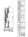
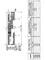
ここで、実施例1におけるステップS102での駆動条件の算出例を図3に示す。図3は、バックライトを構成するN個(本実施例ではN=4)の光源ブロック(図中、光源1、光源2、光源3、光源4と表す)の駆動条件と時間の関係を示す図である。図3の縦軸は光源番号、横軸は時間を示すものとする。本実施例でのバックライトは、光源ブロック1から光源ブロック4まで合計4個で構成されているものとする。光源ブロックの輝度を示すPWM値は1フレーム当たりの最大値(L_all)が4096であるものとする。図3の光源ブロック1を例にとると、光源ブロック1は1フレーム目から3フレーム目までPWM基準クロックの波数が3650カウントとなる時間点灯することになる。なお、図3以降の駆動条件を説明するチャート図では、横方向に延びるグラフのうちグレー部が点灯、白部が消灯を表すものとする。
Here, FIG. 3 shows a calculation example of the drive condition in step S102 in the first embodiment. FIG. 3 shows the relationship between the driving conditions and time of N light source blocks (represented as light source 1,
また、各光源ブロックは、図4(a)で示すように光源ブロック1、2,3,4の順に、遅延時間をもたせた点灯基準タイミングt1、t2、t3、t4を起点として順次点灯開始するものとする。本実施例は、点灯順序が隣接する光源ブロック同士の点灯開始タイミング(点灯基準タイミング)の間隔は、全ての光源ブロック間で等しいものとする。すなわち、遅延時間(Δt=tn+1−tn)は、PWM値で1024に相当する長さであるものとす
る。また、1フレーム期間内で最初に点灯する光源ブロック1の点灯基準タイミングは、フレーム開始タイミングと一致するものとする。なお、これらの条件は本実施例の説明のための一例であり、本発明の適用範囲をこれらの条件を満たす光源制御装置に限定するものではない。
Each light source block starts from lighting reference timings t 1 , t 2 , t 3 , and t 4 with delay times in the order of the light source blocks 1 , 2 , 3 , and 4 as shown in FIG. It is assumed that lighting starts sequentially. In this embodiment, the intervals of the lighting start timings (lighting reference timings) between the light source blocks that are adjacent in the lighting order are assumed to be equal among all the light source blocks. That is, the delay time (Δt = t n + 1 −t n ) is assumed to have a length corresponding to 1024 in terms of PWM value. In addition, the lighting reference timing of the light source block 1 that is first turned on within one frame period is assumed to coincide with the frame start timing. These conditions are merely examples for explaining the present embodiment, and the scope of the present invention is not limited to a light source control device that satisfies these conditions.
次に、ステップS103において、瞬時消費電力算出部16は、光源ブロックn(nは光源番号。n=1〜N)の点灯基準タイミングtnにおける瞬時消費電力値Pnを算出する。
Next, in step S103, the instantaneous power
ここで、前述の図4(a)のようにバックライトを構成する複数の光源ブロックが順次点灯する方式とした場合、1フレーム期間内における瞬時消費電力の最大値は、各光源ブロックの点灯基準タイミングt1からt4 のいずれかにおける瞬時消費電力に等しい。これ
は、各光源ブロックの点灯基準タイミングではいずれかの光源ブロックが必ず点灯するためである。この関係を図4(b)で示す。図4(b)は1フレーム期間を16分割し、各分割時間における瞬時消費電力をサンプリングした例である。また、図4(b)では各分割時間において一つの光源ブロックが点灯したときの消費電力への寄与分を25[W]とする。ここで1フレーム目に注目すると、1フレーム期間内における瞬時消費電力の最大値は75[W]であり、光源ブロック3の点灯基準タイミングt3と光源ブロック4の点灯基
準タイミングt4における瞬時消費電力が当該最大値と等しくなっている。このように、
瞬時消費電力の最大値を算出する場合、1フレーム期間内のすべての分割時間で瞬時消費電力をサンプリングする必要はなく、各光源ブロックの点灯基準タイミングにおける瞬時消費電力のみをサンプリングすればよいことがわかる。
Here, as shown in FIG. 4A, when the plurality of light source blocks constituting the backlight are sequentially turned on, the maximum instantaneous power consumption within one frame period is the lighting reference of each light source block. It is equal to the instantaneous power consumption at any of timings t 1 to t 4 . This is because one of the light source blocks is always turned on at the lighting reference timing of each light source block. This relationship is shown in FIG. FIG. 4B shows an example in which one frame period is divided into 16 and the instantaneous power consumption in each divided time is sampled. Further, in FIG. 4B, the contribution to power consumption when one light source block is turned on in each divided time is 25 [W]. Focusing on the first frame, the maximum value of instantaneous power consumption in one frame period is 75 [W], and the instantaneous consumption at the lighting reference timing t 3 of the light source block 3 and the lighting reference timing t 4 of the
When calculating the maximum value of instantaneous power consumption, it is not necessary to sample the instantaneous power consumption at all the divided times within one frame period, and it is only necessary to sample the instantaneous power consumption at the lighting reference timing of each light source block. Recognize.
また、図4(b)において、2フレーム目の点灯基準タイミングt1と点灯基準タイミン
グt2における瞬時消費電力に着目すると、2フレーム目の点灯基準タイミングt1では1フレーム目で点灯開始した光源ブロック3と光源ブロック4の点灯期間が継続している。また、点灯基準タイミングt2では1フレーム目で点灯開始した光源ブロック4の点灯期
間が継続している。このように、あるフレーム期間内の瞬時消費電力の最大値を算出する
場合、1フレーム前のフレームの各光源ブロックのうち少なくとも点灯期間が次のフレームまで継続する光源ブロックの輝度の情報が必要になる。そのため、前フレームの光源ブロックの輝度の情報を記憶しておく必要がある。そこで、この情報記憶を省略するため、本実施例では、隣接するフレーム間の光源ブロックの駆動条件の変化は微小であると仮定し、次のように瞬時消費電力の最大値の計算を行う。すなわち、計算対象のフレーム(現フレーム)において、点灯期間が次のフレームにまたがる光源ブロックについては、次のフレームの開始タイミング以降の点灯期間と同じ点灯期間が現フレームの開始タイミングから存在していると仮定する。図4(c)に例を示す。図4(c)では、1フレーム目の光源ブロック3、光源ブロック4の点灯期間が2フレーム目にまたがっている。従って、瞬時消費電力算出部16は、光源ブロック3、光源ブロック4については、2フレーム目に含まれている点灯期間が1フレーム目の開始タイミングにも存在しているものとして、1フレーム目の瞬時消費電力の最大値を算出する。なお、記憶容量や処理負荷に問題が無い場合は、前フレームの光源駆動条件の情報(PWM値、輝度など)を記憶しておき、この情報を用いて現フレームの瞬時消費電力の最大値の計算を行うようにしても良い。
In FIG. 4B, when attention is paid to the instantaneous power consumption at the lighting reference timing t 1 and the lighting reference timing t 2 of the second frame, the light source that starts lighting at the first frame at the lighting reference timing t 1 of the second frame. The lighting period of the
次に、ステップS104において、瞬時消費電力算出部16は、N個の瞬時消費電力値Pn(n=1〜N)から瞬時消費電力の最大値Pmaxを算出する。
Next, in step S104, the instantaneous power
次に、ステップS105において、瞬時消費電力比較部17は、瞬時消費電力算出部16が算出した瞬時消費電力の最大値Pmaxと、光源駆動用電源部12の瞬時供給可能電力Plimitとを比較する。
Next, in step S <b> 105, the instantaneous power
ステップS105において、最大瞬時消費電力Pmaxが光源駆動用電源部12の瞬時供給
可能電力Plimitより大きい場合(Pmax>Plimit)、処理はステップS106へ移行す
る。
In step S105, when the maximum instantaneous power consumption P max is larger than the instantaneous supplyable power P limit of the light source driving power supply unit 12 (P max > P limit ), the process proceeds to step S106.
ステップS106では、光源駆動条件算出部15は、最大瞬時消費電力Pmaxとなる点灯
基準タイミングtnにおける瞬時消費電力を閾値以下(ここでは、瞬時供給可能電力Plimit以下)にするための補正係数Cm_tnを算出する。ここで、補正係数Cm_tnは、ステップS102で決定された光源駆動条件(初期駆動条件という)を補正して光源ブロックmを点灯基準タイミングtnにおいて消灯させる光源駆動条件を求めるために用いる係数である。点灯基準タイミングtnにおいて瞬時消費電力が最大瞬時消費電力Pmaxである場合
、初期駆動条件において点灯基準タイミングtnで点灯する光源ブロックのうち1以上の光源ブロックを当該点灯基準タイミングtnで消灯させる必要がある。これは、瞬時消費電力が瞬時供給可能電力Plimitを超えないようにするために必要となる。点灯基準タイ
ミングtnで消灯させることができる光源ブロックが複数ある場合、光源駆動条件算出部15は、当該消灯させることができる光源ブロックの各々について補正係数Cm_tnを算出する。瞬時消費電力が最大瞬時消費電力Pmaxである点灯基準タイミングが複数ある場合
、光源駆動条件算出部15は、当該点灯基準タイミングの各々において、瞬時消費電力が瞬時供給可能電力を超えないようにするための補正係数を算出する。このように補正係数が複数算出される場合、光源駆動条件算出部15は、複数の補正係数のうちから一の補正係数を選択して、初期駆動条件を補正するために用いる(詳細は後述する)。初期駆動条件の補正は、決定された補正係数を、初期駆動条件における全ての光源ブロックのPWM値に一律に乗じることによって行われる。
In step S106, the light source drive
前述の図4(c)の例では、各光源ブロックの点灯基準タイミングにおける瞬時消費電力を算出すると、すべての点灯基準タイミングにおいて75[W]となっているため、Pmax
=75[W]となる。本実施例では光源駆動用電源部12の瞬時供給可能電力量Plimitが
50[W]であるものとする。よって、図4(c)の例では、光源駆動条件算出部15は、点灯基準タイミングt1、t2、t3、およびt4の各々における瞬時消費電力を50[W]以
下とするための補正係数を算出する。
Since in the example of the above-mentioned FIG. 4 (c), it is calculating the instantaneous power consumption in lighting reference timing of each light source block, in all the turn-on reference timing with 75 [W], P max
= 75 [W]. In this embodiment, it is assumed that the instantaneous supplyable power amount P limit of the light source driving
ここで、ステップS106において、光源駆動条件算出部15と瞬時消費電力算出部16、および瞬時消費電力比較部17が行う光源駆動条件の算出方法について、図5から図10を参照し詳細を説明する。
Here, in step S106, the light source driving condition calculation method performed by the light source driving
まず、点灯基準タイミングt1での瞬時消費電力をPlimit以下とするための補正係数算出方法について説明する。補正係数を算出するためには、光源ブロック1から光源ブロック4の輝度をどの程度低下させれば点灯基準タイミングt1での瞬時消費電力をPlimit以下に抑制できるかを計算することになる。t1は光源ブロック1の点灯基準タイミングであ
るから、光源ブロック1は必ず点灯する。よって、光源ブロック1以外の光源ブロック2、光源ブロック3、光源ブロック4を点灯基準タイミングt1で消灯させることでt1における瞬時消費電力を抑制することができる。
First, a correction coefficient calculation method for reducing the instantaneous power consumption at the lighting reference timing t 1 to P limit or less will be described. In order to calculate the correction coefficient, it is calculated how much the luminance of the light source block 1 to the
次に、光源ブロック2、光源ブロック3、光源ブロック4を点灯基準タイミングt1で消
灯するための補正係数Cn_t1(n=2、3、4)の算出方法を、図5を用いて説明する。光源駆動条件算出部15は、点灯基準タイミングt1にて光源ブロックnを消灯するため
の補正係数Cn_t1を、次のように算出する。光源ブロックnのPWM値Ln_onと、光源ブロックnの点灯期間のうち光源ブロックnの点灯基準タイミングtnから補正係数の算出
対象である点灯基準タイミングt1までの点灯期間の長さに相当するPWM値Ln_t1(n
=2、3、4)と、の比を求める。ここでLn_onは1フレーム当たりの最大PWM値L_all(本実施例では4096)から光源ブロックnの消灯時間Ln_offを引いたものと同義
である。
Next, a method of calculating the correction coefficient C n — t1 (n = 2, 3, 4) for turning off the
= 2, 3, 4). Here L N_on is (in this example 4096) the maximum PWM value L _all per frame is synonymous with minus extinguishing time L N_off light source block n from.
まず光源ブロック2は点灯基準タイミングt1において消灯しているため、点灯基準タイ
ミングt1での瞬時消費電力には影響がない。よって、補正係数を算出する必要はない。
Since the first
次に光源ブロック3について考えると、光源ブロック3は、光源ブロック3の点灯基準タイミングt3から点灯基準タイミングt1まで点灯している。よって、光源ブロック3を点灯基準タイミングt1で消灯するための補正係数C3_t1は、t3からt1までのPWM値を
L3_t1とすると、

同様に光源ブロック4を点灯基準タイミングt1で消灯させるための補正係数C4_t1を算
出すると、
点灯基準タイミングt1における瞬時消費電力をPlimit以下とするためには、Pmax−Plimit=75−50=25[W]・・・(3)
から25[W]削減する必要があるため、光源ブロック3か光源ブロック4のどちらかが消灯すればよいことになる。ここで光源ブロック3の補正係数C3_t1と光源ブロック4の補正係数C4_t1を比較すると、
C3_t1>C4_t1・・・(4)
である。C4_t1を初期駆動条件における全ての光源ブロックのPWM値に乗算した場合、光源ブロック3と光源ブロック4の両方が点灯基準タイミングt1において消灯すること
になる。点灯基準タイミングt1においては1つの光源ブロックだけ消灯させれば十分な
ので、ここでは補正係数C3_t1を選択すればよいことになる。
Similarly, when a correction coefficient C 4_t1 for turning off the
In order to set the instantaneous power consumption at the lighting reference timing t 1 to P limit or less, P max −P limit = 75−50 = 25 [W] (3)
Therefore, it is necessary to turn off either the
C 3_t1 > C 4_t1 (4)
It is. When multiplying the C 4_T1 the PWM values of all the light source blocks in the initial drive condition, so that both the
光源駆動条件算出部15は、同様の演算を瞬時消費電力が最大瞬時消費電力Pmaxである
点灯基準タイミングt2、t3、t4においても行う。
点灯基準タイミングt2における補正係数Cn_t2は図6に示すように、C1_t2=0.28
1・・・(5)
C4_t2=0.788・・・(6)
となる。
The light source driving
As shown in FIG. 6, the correction coefficient C n — t2 at the lighting reference timing t 2 is C 1 — t2 = 0.28.
1 ... (5)
C4_t2 = 0.788 (6)
It becomes.
点灯基準タイミングt2では、瞬時消費電力が瞬時供給可能電力Plimitを超えないために瞬時消費電力を25[W]削減すればよい。すなわち、初期駆動条件において点灯基準タイミングt2で点灯する光源ブロックのうち1つだけ消灯すればよい。従って、光源駆動条
件算出部15は、点灯基準タイミングt2における補正係数として、大きい方の補正係数
であるC4_t2を選択する。
In the turn-on reference timing t 2, the instantaneous power consumption may be 25 [W] reduced in order not instantaneous power consumption exceeds the instantaneous available power P limit. That is, it is only necessary to turn off only one of the light source blocks that are turned on at the lighting reference timing t 2 under the initial driving conditions. Accordingly, the light source drive
点灯基準タイミングt3における補正係数Cn_t3は図7に示すように、C1_t3=0.56
1・・・(7)
C2_t3=0.522・・・(8)
となる。
The correction coefficient C n_t3 at the lighting reference timing t 3 is C 1_t3 = 0.56 as shown in FIG.
1 ... (7)
C 2 — t 3 = 0.522 (8)
It becomes.
点灯基準タイミングt3では、瞬時消費電力が瞬時供給可能電力Plimitを超えないために瞬時消費電力を25[W]削減すればよい。すなわち、初期駆動条件において点灯基準タイミングt3で点灯する光源ブロックのうち1つだけ消灯すればよい。従って、光源駆動条
件算出部15は、点灯基準タイミングt3における補正係数として、大きい方の補正係数
であるC1_t3を選択する。
At the lighting reference timing t 3 , the instantaneous power consumption may be reduced by 25 [W] because the instantaneous power consumption does not exceed the instantaneous supplyable power P limit . That is, it is only necessary to turn off only one of the light source blocks that are turned on at the lighting reference timing t 3 under the initial driving conditions. Accordingly, the light source drive
点灯基準タイミングt4における補正係数Cn_t4は図8に示すように、C1_t4=0.84
2・・・(9)
C3_t4=0.445・・・(10)
となる。
As shown in FIG. 8, the correction coefficient C n_t4 at the lighting reference timing t 4 is C 1_t4 = 0.84.
2 ... (9)
C 3 — t 4 = 0.445 (10)
It becomes.
点灯基準タイミングt4では、瞬時消費電力が瞬時供給可能電力Plimitを超えないために瞬時消費電力を25[W]削減すればよい。すなわち、初期駆動条件において点灯基準タイミングt4で点灯する光源ブロックのうち1つだけ消灯すればよい。従って、光源駆動条
件算出部15は、点灯基準タイミングt4における補正係数として、大きい方の補正係数
であるC1_t4を選択する。
In the turn-on reference timing t 4, the instantaneous power consumption may be 25 [W] reduced in order not instantaneous power consumption exceeds the instantaneous available power P limit. That is, it is only necessary to turn off only one of the light source blocks that are turned on at the lighting reference timing t 4 under the initial driving conditions. Accordingly, the light source drive
以上が図2のステップS106における補正係数Cm_tnの算出処理である。 The above is the calculation process of the correction coefficient C m_tn in step S106 of FIG.
次に、ステップS107において、光源駆動条件算出部15は、補正係数の最小値を選択する。図9は、ステップS106で算出した、点灯基準タイミングt1、t2、t3、およ
びt4の瞬時消費電力を瞬時供給可能電力Plimit以下に抑制するための補正係数の一覧である。各点灯基準タイミングの補正係数Cm_tnのうち、最小の値を用いて初期駆動条件を補正すれば、複数の光源ブロック(光源ブロック1〜4)の輝度バランスを保ったまま全ての点灯基準タイミングで瞬時消費電力を瞬時供給可能電力Plimit以下に抑制できる。
図9の例では、光源駆動条件算出部15は、C1_t3を、初期駆動条件の補正に用いる補正係数Cとして選択する。
Next, in step S107, the light source driving
In the example of FIG. 9, the light source driving condition calculation unit 15 selects C 1 — t3 as the correction coefficient C used for correcting the initial driving condition.
次に、ステップS108において、光源駆動条件算出部15は、S107にて算出した補正係数Cを初期駆動条件の全ての光源ブロックのPWM値に乗算し、新たな光源駆動条件を算出する。このようにして得られる補正後の光源駆動条件を図10に示す。
Next, in step S108, the light source driving
最後に、ステップS109において、光源駆動回路部11は、光源駆動条件算出部15が算出した補正後の光源駆動条件に従って光源部10を駆動し、各光源ブロックを点灯させる。
Finally, in step S109, the light source
以上が、実施例1の瞬時消費電力抑制処理である。本実施例によると、ローカルディミング制御を行うバックライトにおいて、複数の光源ブロック(光源ブロック1〜4)の輝度バランスを保ったまま、バックライトの瞬時消費電力が電源の瞬時供給可能電力を超えることを抑制できる。
なお、図1(C)のように光源ブロックがマトリクス配置されている場合は、マトリクス配置されている全光源ブロック1A〜3Dの点灯開始タイミングごとに最大瞬時消費電力Pmaxを算出する。PmaxがPlimitを超える場合は、Pmaxとなる点灯基準タイミングを開始タイミングとする光源ブロック以外の光源について補正係数を算出し、算出した補正係数を全光源ブロック1A〜3DのPWM値に乗算することとする。なお、一般的に各光源ブロックの点灯開始タイミングは本バックライトと組み合わせる液晶表示装置の走査方向に合わせるのが望ましい。組み合わせる液晶表示装置が縦方向に順次走査であれば、行方向に並んでいる光源ブロックの点灯開始タイミングを一致させることで演算数を削減することも可能である。
The above is the instantaneous power consumption suppression processing of the first embodiment. According to this embodiment, in a backlight that performs local dimming control, the instantaneous power consumption of the backlight exceeds the power that can be instantaneously supplied from the power source while maintaining the luminance balance of the plurality of light source blocks (light source blocks 1 to 4). Can be suppressed.
When the light source blocks are arranged in a matrix as shown in FIG. 1C, the maximum instantaneous power consumption P max is calculated for each lighting start timing of all the light source blocks 1A to 3D arranged in the matrix. When P max exceeds P limit , a correction coefficient is calculated for light sources other than the light source block whose starting timing is the lighting reference timing that becomes P max, and the calculated correction coefficient is multiplied by the PWM value of all the light source blocks 1A to 3D. I decided to. In general, it is desirable to match the lighting start timing of each light source block with the scanning direction of the liquid crystal display device combined with the backlight. If the combined liquid crystal display device sequentially scans in the vertical direction, the number of operations can be reduced by matching the lighting start timings of the light source blocks arranged in the row direction.
(実施例2)
実施例2では、ローカルディミング制御におけるコントラスト比の低下を抑制するため、初期駆動条件において最も高輝度の光源ブロックを補正の対象から外して補正を行う例を説明する。図3の例では、光源ブロック1の輝度が最も高い(PWM値が最も大きい)。従って、本実施例では、瞬時消費電力が最大値Pmaxである点灯基準タイミングにおける
瞬時消費電力を瞬時供給可能電力Plimit以下にするための補正係数を算出する際、光源
ブロック1については消灯させる対象から外して補正係数を求める。
(Example 2)
In the second embodiment, an example will be described in which correction is performed by removing the light source block having the highest luminance from the correction target in the initial drive condition in order to suppress a decrease in contrast ratio in local dimming control. In the example of FIG. 3, the luminance of the light source block 1 is the highest (the PWM value is the largest). Therefore, in this embodiment, the light source block 1 is turned off when calculating the correction coefficient for making the instantaneous power consumption at the lighting reference timing at which the instantaneous power consumption is the maximum value P max equal to or less than the instantaneous supplyable power P limit . The correction coefficient is obtained by removing from the target.
以下、図2のステップS106で行う補正係数算出処理について実施例1との違いを中心に説明する。 Hereinafter, the correction coefficient calculation process performed in step S106 of FIG. 2 will be described focusing on differences from the first embodiment.
まず、図2のステップS106において、光源駆動条件算出部15は、実施例1と同様、各光源ブロックの点灯基準タイミングにおける瞬時消費電力を算出し、最大瞬時消費電力を求め、瞬時消費電力が最大値Pmaxである点灯基準タイミングを求める。実施例1で説
明したように、図4(c)の例では、この条件を満たす点灯基準タイミングは、t1、t2、t3、およびt4の全てである。
First, in step S106 of FIG. 2, the light source driving
実施例2での点灯基準タイミングt1における瞬時消費電力をPlimit以下とするための補正係数算出方法について図11を用いて説明する。点灯基準タイミングt1では、光源ブ
ロック1が必ず点灯する。よって、光源ブロック1以外の光源ブロック2、光源ブロック3、光源ブロック4を点灯基準タイミングt1で消灯させることで瞬時消費電力を抑制す
ることができる。初期駆動条件において、点灯基準タイミングt1では光源ブロック2は
消灯しているため、補正係数は光源ブロック3、光源ブロック4についてのみ算出する。
A correction coefficient calculation method for setting the instantaneous power consumption at the lighting reference timing t 1 in the second embodiment to P limit or less will be described with reference to FIG. In the turn-on reference timing t 1, the light source block 1 is always turned on. Therefore, the
光源ブロック3、光源ブロック4をt1で消灯するための補正係数Cn_t1(n=3、4)
を前述の実施例1と同様に算出すると図11に示すように、
Plimit=75−50=25[W]・・・(13)
から25[W]削減する必要があるため、光源ブロック3か光源ブロック4のどちらかが消灯すればよいことになる。ここで光源ブロック3の補正係数C3_t1と光源ブロック4の補正係数C4_t1を比較すると、
C3_t1>C4_t1・・・(14)
である。C4_t1を初期駆動条件における全ての光源ブロックのPWM値に乗算した場合、光源ブロック3と光源ブロック4の両方が点灯基準タイミングt1において消灯すること
になる。点灯基準タイミングt1においては1つの光源ブロックだけ消灯させれば十分な
ので、ここでは補正係数C3_t1を選択すればよいことになる。点灯基準タイミングt1に
ついては、補正係数は、実施例1と同様の結果となる。
Correction coefficient C n — t1 (n = 3, 4) for turning off the
Is calculated in the same manner as in the first embodiment, as shown in FIG.
P limit = 75-50 = 25 [W] (13)
Therefore, it is necessary to turn off either the
C 3_t1 > C 4_t1 (14)
It is. When multiplying the C 4_T1 the PWM values of all the light source blocks in the initial drive condition, so that both the
次に点灯基準タイミングt2における補正係数の算出について説明する。点灯基準タイミ
ングt2では、初期駆動条件において、光源ブロック1、光源ブロック2、光源ブロック
4が点灯しているが、t2は光源ブロック2の点灯基準タイミングであるため、光源ブロ
ック2は消灯の対象にはできない。また、光源ブロック1は1フレーム目において最も高輝度の光源であるため、実施例2では輝度補正をしない(t2における消灯の対象とはし
ない)。よって、点灯基準タイミングt2では光源ブロック4を消灯させる輝度補正を行
うことで瞬時消費電力を抑制することになる。点灯基準タイミングt2で光源ブロック4
の瞬時消費電力を抑制するための補正係数C4_t2は、図12で示すように
C4_t2=0.788・・・(15)
となる。
Next, calculation of the correction coefficient at the lighting reference timing t 2 will be described. At the lighting reference timing t 2 , the light source block 1, the
As shown in FIG. 12, the
It becomes.
同様に、点灯基準タイミングt3、t4においても計算する。点灯基準タイミングt3では、初期駆動条件において、光源ブロック1と光源ブロック2が点灯しているが、1フレーム目では最大輝度の光源ブロック1は補正(消灯)対象とはしないので、光源ブロック2が補正(消灯)対象となる。従って、点灯基準タイミングt3における補正係数C2_t3は
図13に示すように、
C2_t3=0.522・・・(16)
となる。
Similarly, the calculation is performed at the lighting reference timings t 3 and t 4 . At the lighting reference timing t 3 , the light source block 1 and the
C 2 — t 3 = 0.522 (16)
It becomes.
次に、点灯基準タイミングt4では、初期駆動条件において、光源ブロック1と光源ブロック3が点灯しているが、1フレーム目では最大輝度の光源ブロック1は補正(消灯)対象とはしないので、光源ブロック3が補正(消灯)対象となる。従って、点灯基準タイミングt4における補正係数C3_t4は図14に示すように、
C3_t4=0.445・・・(17)
となる。
Next, the turn-on reference timing t 4, in the initial drive condition, since the light source block 1 and the
C 3 — t 4 = 0.445 (17)
It becomes.
上記で算出した、点灯基準タイミングt1、t2、t3、およびt4の瞬時消費電力を瞬時供給可能電力Plimit以下に抑制するための補正係数の一覧を図15に示す。各点灯基準タ
イミングの補正係数のうち、最小の値を用いて初期駆動条件を補正すれば、光源ブロック
2〜4の輝度バランスを保ったまま、すべての点灯基準タイミングで瞬時消費電力を瞬時供給可能電力Plimit以下に抑制できる。図15の例では、光源駆動条件算出部15は、
ステップS107において、C3_t4を、初期駆動条件の補正に用いる補正係数Cとして選択する。
FIG. 15 shows a list of correction coefficients for suppressing the instantaneous power consumption calculated at the lighting reference timings t 1 , t 2 , t 3 , and t 4 below the instantaneous supplyable power P limit . If the initial drive condition is corrected using the minimum value among the correction coefficients for each lighting reference timing, instantaneous power consumption can be instantaneously supplied at all lighting reference timings while maintaining the luminance balance of the light source blocks 2 to 4. The power can be suppressed to P limit or less. In the example of FIG. 15, the light source drive
In step S107, C 3_t4 is selected as the correction coefficient C used for correcting the initial drive condition.
ステップS108において、光源駆動条件算出部15は、S107にて算出した補正係数Cを、初期駆動条件における、輝度を維持する光源ブロック1以外の光源ブロック(光源ブロック2、3,4)のPWM値に乗算し、新たな光源駆動条件を算出する。このようにして得られる補正後の光源駆動条件を図16に示す。
In step S108, the light source drive
本実施例によると、ローカルディミング制御を行うバックライトにおいて、初期駆動条件において最も明るい光源ブロックの輝度を維持したまま、バックライトの瞬時消費電力が電源の瞬時供給可能電力を超えることを抑制できる。本実施例では、実施例1で得られる効果に加えて、ローカルディミングによるコントラスト向上効果の低下を抑制できるという更なる効果が得られる。 According to the present embodiment, in a backlight that performs local dimming control, it is possible to suppress the instantaneous power consumption of the backlight from exceeding the instantaneous power supply capability of the power supply while maintaining the brightness of the brightest light source block in the initial driving condition. In the present embodiment, in addition to the effects obtained in the first embodiment, a further effect that the reduction in contrast improvement effect due to local dimming can be suppressed can be obtained.
(実施例3)
実施例3は、光源部10が赤色、緑色、青色など複数色の光源で構成され、それぞれの光源を所定の輝度比で点灯させることによって所定の色度で点灯するバックライトに本発明を適用した場合の実施例である。ここでは、上述の実施例における各光源ブロックが、複数色の光源の組み合わせを一又は複数備えて構成されているものとして説明する。
(Example 3)
In the third embodiment, the present invention is applied to a backlight in which the
実施例3の場合、光源駆動条件算出部15は、光源の色ごとに各点灯基準タイミングにおける瞬時消費電力を算出し、色ごとに補正係数の最小値を求める。そして、光源駆動条件算出部15は、色ごとに求められた補正係数のうちの最小値を、初期駆動条件の補正に用いる補正係数として決定し、初期駆動条件における全色のPWM値に一律に乗算する。これにより、複数色の光源の輝度比率を保ったまま、すなわちバックライトの色度の変動を抑えながら、瞬時消費電力を瞬時供給可能電力Plimit以下に抑制することができる。
In the case of the third embodiment, the light source driving
以下、図2のステップS106で行う補正係数算出処理について実施例1との違いを中心に説明する。 Hereinafter, the correction coefficient calculation process performed in step S106 of FIG. 2 will be described focusing on differences from the first embodiment.
図2のステップS106において、光源駆動条件算出部15は、実施例1と同様、光源ブロックを構成する光源の色ごとに、点灯基準タイミングにおける瞬時消費電力の算出、最大瞬時消費電力の算出、瞬時消費電力が最大値である点灯基準タイミングの算出を行う。図17(a)は赤色光源の瞬時消費電力、図17(b)は緑色光源の瞬時消費電力、図17(c)は青色光源の瞬時消費電力を示す。図17(a)に示すように、赤色光源では、瞬時消費電力が最大値である点灯基準タイミングはt3である。図17(b)に示すように、緑色光源では、瞬時消費電力が最大値である点灯基準タイミングはt1、t2、t3、
およびt4の全てである。図17(c)に示すように、青色光源では、瞬時消費電力が最
大値である点灯基準タイミングはt3である。光源駆動条件算出部15は、赤色光源及び青色光源については、点灯基準タイミングt3における瞬時消費電力をPlimit以下とす
るための補正係数を求める。また、緑色光源については、点灯基準タイミングt1、t2、t3、およびt4における瞬時消費電力をPlimit以下とするための補正係数を求める。点
灯基準タイミングtnにおける補正係数の求め方は実施例1と同じである。すなわち、光源駆動条件算出部15は、初期駆動条件において点灯基準タイミングtnで点灯している光源ブロックのうち光源ブロックn以外の光源ブロック(補正候補の光源ブロック)の各々について、補正係数を算出する。補正係数は、補正候補の光源ブロックが点灯基準タイミングtnにおいて消灯するために、当該補正候補の光源ブロックのPWM値に乗じるべき係数である。また、光源駆動条件算出部15は、点灯基準タイミングtnにおける瞬時
消費電力を電源の瞬時供給可能電力Plimit以下とするために点灯基準タイミングtnに
おいて消灯させるべき光源ブロックの数を求める。消灯させるべき光源ブロック数をXとした場合、光源駆動条件算出部15は、算出した補正係数のうち、大きい方からX番目の補正係数を点灯基準タイミングtnの補正係数とする。
In step S106 of FIG. 2, the light source drive
And all of t 4 . As shown in FIG. 17 (c), the blue light source, the turn-on reference timing instantaneous power consumption is the maximum value is t 3. Light source driving
本実施例では、Plimitは色ごとに50[W]とする。図17(a)、図17(b),図1
7(c)より、瞬時消費電力が最大値となる点灯基準タイミングは、赤色光源はt3、緑色光源はt1、t2、t3、およびt4、青色光源はt3でありおいて、最大瞬時消費電力はいずれも75[W]である。よって、消灯させるべき光源ブロック数Xは、これら全ての点灯基準タイミングについて、1である。また、図17(a)、図17(b)、図17(c)より、瞬時消費電力が最大値となる各点灯基準タイミングに関して、補正候補となる光源ブロック数は、いずれも2である。よって、光源駆動条件算出部15は、赤色光源のt3、緑色光源のt1、t2、t3、およびt4、青色光源のt3の各点灯基準タイミングに関して、図18に示すようにそれぞれ2つの補正係数を算出する。そして、算出した補正係数のうち大きい方の補正係数を、その点灯基準タイミングの補正係数とする。
In this embodiment, P limit is set to 50 [W] for each color. 17 (a), 17 (b), and 1
Than 7 (c), the turn-on reference timing instantaneous power becomes the maximum value, the red light source is t 3, the green light source is t 1, t 2, t 3 , and t 4, the blue light source is kept there at t 3 The maximum instantaneous power consumption is 75 [W] in all cases. Therefore, the number X of light source blocks to be turned off is 1 for all these lighting reference timings. Further, from FIGS. 17A, 17B, and 17C, the number of light source blocks that are correction candidates is 2 for each lighting reference timing at which the instantaneous power consumption becomes the maximum value. Therefore, the light source drive
光源駆動条件算出部15は補正係数を算出すべき点灯基準タイミングが複数あった場合、すなわち瞬時消費電力が最大瞬時消費電力Pmaxである点灯基準タイミングが複数あった
場合、各点灯基準タイミングに関する補正係数のうち最小値を補正係数として決定する。この補正係数の決定は、本実施例では、色ごとに行われる。図18に示すように、赤色光源及び青色光源については、補正係数を算出すべき点灯基準タイミングは1であるが、緑色光源については、補正係数を算出すべき点灯基準タイミングは4である。従って、光源駆動条件算出部15は、緑色光源については、4つの点灯基準タイミングそれぞれについて補正係数を算出し、そのうちの最小値を緑色光源の補正係数として決定する。
When there are a plurality of lighting reference timings at which the correction coefficient is to be calculated, that is, when there are a plurality of lighting reference timings whose instantaneous power consumption is the maximum instantaneous power consumption Pmax , the light source driving
図18に示すように、から赤色光源の瞬時消費電力を補正するための補正係数は、
C1_t3_R=0.679・・・(18)
緑色光源の瞬時消費電力を補正するための補正係数は、
C1_t3_G=0.561・・・(19)
青色光源の瞬時消費電力を補正するための補正係数は、
C2_t3_B=0.994・・・(20)
となる。
As shown in FIG. 18, the correction coefficient for correcting the instantaneous power consumption of the red light source is
C 1_t3_R = 0.679 (18)
The correction factor for correcting the instantaneous power consumption of the green light source is
C 1_t3_G = 0.561 (19)
The correction factor for correcting the instantaneous power consumption of the blue light source is
C 2_t3_B = 0.994 (20)
It becomes.
本実施例では、光源駆動条件算出部15は、このようにして各色の光源について算出した補正係数のうちの最小値を、初期駆動条件の補正に用いる補正係数として決定する。図18の例では、各色の光源について算出された補正係数のうち、最小のものは、緑色光源の補正係数である
C1_t3_G=0.561・・・(21)
である。よって、光源駆動条件算出部15は、C1_t3_Gを初期駆動条件の補正に用いる補正係数Cとして選択し、初期駆動条件の全ての光源ブロックの全色のPWM値に乗算し、新たな光源駆動条件を算出する。このようにして得られる補正後の各色の光源駆動条件を図19(a)、図19(b)、図19(c)に示す。図19(a)、図19(b)、図19(c)によると全色の点灯基準タイミングにおいて瞬時消費電力がPlimit以下となっ
ていることがわかる。
In this embodiment, the light source driving
It is. Therefore, the light source drive condition calculation unit 15 selects C 1_t3_G as the correction coefficient C used for correcting the initial drive condition, multiplies the PWM values of all the colors of all the light source blocks under the initial drive condition, and creates a new light source drive condition. Is calculated. FIG. 19A, FIG. 19B, and FIG. 19C show the light source driving conditions for each color after correction obtained in this way. 19 (a), 19 (b), and 19 (c), it can be seen that the instantaneous power consumption is equal to or less than P limit at the lighting reference timing for all colors.
本実施例によると、バックライト光源が赤/緑/青など複数色の光源で構成されている場合でも、所望の色度を維持した状態で瞬時消費電力を抑制できることがわかる。 According to the present embodiment, it can be seen that even when the backlight light source is composed of light sources of a plurality of colors such as red / green / blue, instantaneous power consumption can be suppressed while maintaining a desired chromaticity.
(実施例4)
実施例4は、図1(A)の光源駆動条件算出部15による補正係数の演算負荷を抑制する
ことを図った実施例である。大型液晶表示装置では、バックライトを構成する光源ブロックの数が多くなる。バックライトを構成する光源ブロックの数の増大によって点灯基準タイミングの数も増えるため、補正係数演算処理の負荷が増大することが考えられる。そこで、実施例4では、補正係数の算出方法を簡略化した実施例を説明する。これまでの実施例では、瞬時消費電力が最大値Pmaxである点灯基準タイミングtnに関して、当該点灯
基準タイミングtnにおける瞬時消費電力を光源駆動用電源部12の瞬時供給可能電力Plimit以下とするために次のような処理を行っていた。すなわち、当該点灯基準タイミン
グtnにおいて消灯させるべき光源ブロック数を決定し、補正候補の光源ブロックを当該点灯基準タイミングtnにおいて消灯させるような補正係数を補正候補の光源ブロックの各々について個別に算出した。そして、消灯させるべき光源ブロック数に応じて、算出した補正係数のうちから最適な補正係数を選択し、初期駆動条件の補正に用いる補正係数を決定していた。実施例4ではこの計算を簡略化し、光源駆動条件算出部15は、瞬時供給可能電力量Plimitと瞬時消費電力の最大値Pmaxとの比率を算出し、これを補正係数とする。以下、図21(A)のフローチャートを参照しながら説明する。図21(A)のフローチャートは、本実施例における光源駆動条件の補正処理を表す。図2のフローチャートと同一の処理を行うステップについては図2のフローチャートと同じ符号を付し、詳細な説明を省略する。ステップS105で瞬時消費電力の最大値PmaxがPlimitを超えていると判定された場合、光源駆動条件算出部15はステップS500に進み、以下の式(22)によって補正係数を算出する。
The fourth embodiment is an embodiment in which the calculation load of the correction coefficient by the light source driving
続くステップS108において、光源駆動条件算出部15は、ステップS500で求めた補正係数Cを用いて初期駆動条件の補正を行う(各光源ブロックのPWM値に補正係数を乗算する)。その後、処理はステップS103に戻り、瞬時消費電力算出部16は、ステップS108で補正後の光源駆動条件に基づいて、再度、各点灯基準タイミングでの瞬時消費電力の最大値Pmaxを算出する。算出結果に基づいて瞬時消費電力比較部17がステ
ップS105で比較を行い、最大値Pmaxが瞬時供給可能電力量Plimitを超えていると判定された場合、光源駆動条件算出部15は、再度、ステップS500において式(22)を用いて補正係数を算出する。そして、ステップS108において、求まった補正係数Cを用いて前記補正後の光源駆動条件を更に補正する。そして、処理は再度ステップ103に戻り、瞬時消費電力算出部16は、当該補正後の光源駆動条件に基づいて、再度、瞬時消費電力を算出し、ステップS105の判定が行われる。実施例4ではこの一連の処理をステップS105で瞬時消費電力の最大値Pmaxが瞬時供給可能電力量Plimit以下と判定されるまで繰り返す。ステップS105で瞬時消費電力の最大値Pmaxが瞬時供給可能電
力量Plimit以下と判定されると、処理はステップS109に進み、最も新しい補正後の
光源駆動条件に基づき光源が駆動される。
In subsequent step S108, the light source drive
図20(a)の例に基づいて説明する。図20(a)は、入力される映像信号の解析結果に基づいて光源駆動条件算出部15が求めた光源ブロック1,2,3,4の初期駆動条件を示す。瞬時供給可能電力量Plimitは、実施例1と同様50[W]とする。光源ブロック
1から光源ブロック4の輝度が図20(a)に示す条件の場合、瞬時消費電力の最大値Pmax=75[W]であるから、補正係数Cは、
件においても瞬時供給可能電力量Plimitを超えている。そのため、光源駆動条件算出部
15は、再度、式(22)によって補正係数を算出し、求まった補正係数Cを用いて図20(b)に示す1回目の補正後の光源駆動条件を補正する。このようにして得られる2回目の補正後の光源駆動条件、及びこの2回目の補正後の光源駆動条件に基づき算出される各点灯基準タイミングでの瞬時消費電力を図20(c)に示す。図20(c)に示すように、各点灯基準タイミングにおける瞬時消費電力の最大値Pmaxは、いずれも瞬時供給可
能電力量Plimit以下となっているため、光源駆動条件算出部15は、繰り返し演算を終
了する。
A description will be given based on the example of FIG. FIG. 20A shows the initial driving conditions of the light source blocks 1, 2, 3, and 4 obtained by the light source driving
本実施例によると、補正係数の演算処理の負荷を軽減できるので、光源数や光源ブロック数が多いバックライトにおいても好適に瞬時消費電力を抑制できる。 According to this embodiment, the load of the correction coefficient calculation process can be reduced, so that instantaneous power consumption can be suitably suppressed even in a backlight having a large number of light sources and light source blocks.
本実施例において、補正係数の算出に用いる瞬時供給可能電力量Plimitを、光源駆動用
電源部12の仕様に対して余裕を持たせたより小さな値にすることで、繰り返し演算数を削減することができ、より一層の演算負荷の軽減が可能になる。
なお、図21(A)のステップS500の処理を省略し、補正係数Cを予め定められる固定値(例えば、0.80、0.60、0.50などの任意の値)としてもよい。この場合は、図21(B)に示すフローチャートの処理が行われる。この場合、補正係数Cを算出する必要がないため、演算負荷がさらに低減できる。予め定められる固定値の補正係数Cは、製品出荷前に任意の値が設定される。製品出荷前に補正係数Cを複数個用意しておき、製品出荷後にユーザが複数の補正係数のうちの任意の値を選択できるようにしてもよい。
In this embodiment, the number of repetitive operations can be reduced by setting the instantaneous supplyable power amount P limit used for calculating the correction coefficient to a smaller value with a margin with respect to the specifications of the light source driving
Note that the processing in step S500 in FIG. 21A may be omitted, and the correction coefficient C may be set to a predetermined fixed value (for example, an arbitrary value such as 0.80, 0.60, 0.50). In this case, the process of the flowchart shown in FIG. In this case, since it is not necessary to calculate the correction coefficient C, the calculation load can be further reduced. A predetermined fixed value correction coefficient C is set to an arbitrary value before product shipment. A plurality of correction coefficients C may be prepared before product shipment, and the user may select an arbitrary value from among the plurality of correction coefficients after product shipment.
(実施例5)
実施例1から実施例4において、瞬時消費電力の抑制処理を行った直後のフレームで瞬時消費電力の抑制処理を解除すると、高輝度と低輝度を繰り返す現象が発生する。実施例5では、上記の高輝度と低輝度を繰り返す現象を防止するため、瞬時消費電力抑制処理の実行後は、瞬時消費電力の最大値Pmaxが所定の閾値である補正解除電力以下になるまで、
瞬時消費電力抑制処理を継続するヒステリシス制御を行う。補正解除電力は、光源駆動用電源部12の瞬時供給可能電力量Plimitよりも小さい所定値である。
(Example 5)
In the first to fourth embodiments, when the instantaneous power consumption suppression process is canceled in the frame immediately after the instantaneous power consumption suppression process is performed, a phenomenon in which high luminance and low luminance are repeated occurs. In Example 5, in order to prevent the phenomenon of repeating the high luminance and the low luminance described above, after execution of the instantaneous power consumption suppression process, the maximum value P max of the instantaneous power consumption becomes equal to or less than the correction cancellation power that is a predetermined threshold value. Until,
Hysteresis control is performed to continue the instantaneous power consumption suppression process. The correction cancellation power is a predetermined value smaller than the instantaneously suppliable power amount P limit of the light source driving
図22に本実施例のヒステリシス制御を行った場合の最大瞬時消費電力Pmaxの時間推移
の一例を示す。横軸は時間を表し、縦軸は最大瞬時消費電力Pmaxを表す。
FIG. 22 shows an example of the time transition of the maximum instantaneous power consumption P max when the hysteresis control of this embodiment is performed. The horizontal axis represents time, and the vertical axis represents the maximum instantaneous power consumption Pmax .
図22は補正解除電力を40[W]とした場合のヒステリシス制御例である。図22では、タイミングTon1で最大瞬時消費電力PmaxがPlimitに達したため瞬時消費電力抑制処理
が開始されたのち、タイミングThで最大瞬時消費電力PmaxがPlimit以下になっている
。しかし、タイミングThで瞬時消費電力抑制処理を解除すると、最大瞬時消費電力が再
びPlimitに達して瞬時消費電力抑制処理が再度実行されることとなる場合がある。そう
すると、短時間の間に輝度の変動が発生することとなり、表示品質低下の要因となる。そこで、本実施例では、図22のタイミングTon1にて瞬時消費電力抑制処理を開始したの
ち、最大瞬時消費電力Pmaxが補正解除電力に達するタイミングToffまで瞬時消費電力抑制処理の解除は行わない。
FIG. 22 shows an example of hysteresis control when the correction cancellation power is 40 [W]. In Figure 22, after the instantaneous electric power consumption suppressing process for maximum instantaneous power P max reached P limit at the timing T on1 is started, the maximum instantaneous power consumption P max is equal to or less than P limit at the timing T h. However, when releasing the instantaneous electric power consumption suppressing process at timing T h, there is a case where the instantaneous power consumption control processing maximum instantaneous power consumption is reached again P limit is to be executed again. As a result, luminance fluctuation occurs in a short time, which causes a reduction in display quality. Therefore, in this embodiment, after the start of the instantaneous electric power consumption suppressing process at the timing T on1 in FIG 22, the release of the instantaneous electric power consumption suppressing process to the timing T off the maximum instantaneous power consumption P max reached correct release power done Absent.
本実施例によると、瞬時消費電力抑制処理を行うバックライトにおいて、最大瞬時消費電力Pmaxが瞬時供給可能電力量Plimitに近い条件下でバックライトの輝度が頻繁に変動す
ることを抑制できる。
According to the present embodiment, in the backlight that performs the instantaneous power consumption suppression process, it is possible to suppress the backlight brightness from fluctuating frequently under the condition that the maximum instantaneous power consumption P max is close to the instantaneous power supply P limit .
以上、実施例1から実施例5までが本発明の実施例となるが、本発明は以上説明した実施例に限定されるものではなく、種々の変形が可能である。 As described above, Examples 1 to 5 are examples of the present invention, but the present invention is not limited to the examples described above, and various modifications are possible.
例えば、瞬時消費電力量の計算は、光源がLEDの場合、各光源に流す電流量と順方向降下電圧との乗算によって求められる。順方向降下電圧を検出する手段がない場合は、光源の順方向降下電圧の代表値で代替してもよい。このようにして算出された瞬時消費電力を全光源(光源を直列接続している場合は、光源列の数)について算出した上で合計し、バックライト全体の瞬時消費電力とする。 For example, when the light source is an LED, the instantaneous power consumption is calculated by multiplying the amount of current flowing through each light source and the forward voltage drop. If there is no means for detecting the forward voltage drop, a representative value of the forward voltage drop of the light source may be substituted. The instantaneous power consumption calculated in this way is calculated for all light sources (or the number of light source arrays in the case where light sources are connected in series) and then summed to obtain the instantaneous power consumption of the entire backlight.
また、バックライトを構成する光源ごとに電流量が異なる場合は、瞬時消費電力算出の際、光源ごとに異なる電流量と順方向降下電圧を乗算して瞬時消費電力を算出してもよい。
また、各実施例の説明では点灯開始タイミングを固定して演算したが、本バックライトと組み合わせる液晶表示装置の特性によっては点灯終了タイミングを固定した点灯方法とするほうが動画応答性の観点で望ましい場合もある。このような点灯方法の場合、各光源ブロックの点灯終了タイミングが最大瞬時消費電力となるため、各光源の点灯終了タイミングにおける最大瞬時消費電力が瞬時供給可能電力量以下となるような補正値を算出してもよい。
Further, when the amount of current differs for each light source constituting the backlight, the instantaneous power consumption may be calculated by multiplying the amount of current different for each light source and the forward drop voltage when calculating the instantaneous power consumption.
In the description of each embodiment, the calculation is performed with the lighting start timing fixed. However, depending on the characteristics of the liquid crystal display device combined with the backlight, it is preferable to use the lighting method with the lighting end timing fixed from the viewpoint of moving image response. There is also. In such a lighting method, since the lighting end timing of each light source block is the maximum instantaneous power consumption, a correction value is calculated so that the maximum instantaneous power consumption at the lighting end timing of each light source is equal to or less than the instantaneous power supply amount. May be.
10 光源、11 光源駆動回路部、12 光源駆動用電源部、14 映像信号解析部、15 光源駆動条件算出部、16 瞬時消費電力算出部、17 瞬時消費電力比較部
DESCRIPTION OF
Claims (10)
前記複数の光源を所定の遅延時間おきに順次点灯させる駆動手段と、
入力される画像信号に応じて前記複数の光源の各々の輝度を決定するとともに、当該輝度に基づき、前記複数の光源の各々の1フレーム期間における点灯期間の長さを示すPWM(Pulse Width Modulation)値を決定する決定手段と、
決定されたPWM値に基づき、順次点灯される前記複数の光源の各々の点灯期間の開始又は終了の基準となる点灯基準タイミングにおける前記電源の消費電力を算出する算出手段と、
前記算出手段により算出される消費電力が所定の閾値を超える場合、順次点灯される前記複数の光源の各々の前記点灯基準タイミングにおける消費電力が前記閾値以下となるように、前記複数の光源のうちの少なくとも一部の光源の点灯期間を短くする補正を行い、前記複数の光源の各々の前記点灯基準タイミングにおいて同時点灯する光源の数を制限する補正手段と、
を備える光源制御装置。 A power supply for supplying power to a plurality of light sources;
Driving means for sequentially lighting the plurality of light sources at predetermined delay times;
PWM (Pulse Width Modulation) that determines the brightness of each of the plurality of light sources according to an input image signal and indicates the length of the lighting period in each frame period of the plurality of light sources based on the brightness A determination means for determining a value;
Calculation means for calculating the power consumption of the power source at a lighting reference timing that is a reference for starting or ending the lighting period of each of the plurality of light sources that are sequentially turned on based on the determined PWM value;
When the power consumption calculated by the calculating means exceeds a predetermined threshold, among the plurality of light sources, the power consumption at the lighting reference timing of each of the plurality of light sources that are sequentially turned on is equal to or less than the threshold value. Correcting means for shortening the lighting period of at least some of the light sources, and limiting the number of light sources that are simultaneously turned on at the lighting reference timing of each of the plurality of light sources,
A light source control device comprising:
、予め定められる補正係数を用いて前記複数の光源のうちの少なくとも一部の光源の点灯期間を短くする補正を行う請求項1に記載の光源制御装置。 The correction unit corrects the lighting period of at least some of the plurality of light sources using a predetermined correction coefficient when the power consumption calculated by the calculation unit exceeds a predetermined threshold. The light source control device according to claim 1 which performs.
前記バックライトの前面に配置され、入力される画像信号に応じて前記バックライトからの光の透過率を調節することにより画像を表示する液晶表示パネルと、
を備える液晶表示装置。 A backlight comprising a plurality of light sources, wherein the plurality of light sources are controlled by the light source control device according to any one of claims 1 to 6,
A liquid crystal display panel that is disposed in front of the backlight and displays an image by adjusting the transmittance of light from the backlight according to an input image signal;
A liquid crystal display device comprising:
前記決定手段は、各分割領域に表示される画像に対応する画像信号に応じて各分割領域に対応する光源の輝度を決定する請求項7に記載の液晶表示装置。 The plurality of light sources correspond to each of a plurality of divided areas dividing the image display area of the liquid crystal display panel,
The liquid crystal display device according to claim 7, wherein the determining unit determines the luminance of the light source corresponding to each divided region in accordance with an image signal corresponding to an image displayed in each divided region.
前記複数の光源を所定の遅延時間おきに順次点灯させる駆動工程と、
入力される画像信号に応じて前記複数の光源の各々の輝度を決定するとともに、当該輝度に基づき、前記複数の光源の各々の1フレーム期間における点灯期間の長さを示すPWM(Pulse Width Modulation)値を決定する決定工程と、
決定されたPWM値に基づき、順次点灯される前記複数の光源の各々の点灯期間の開始又は終了の基準となる点灯基準タイミングにおける、前記複数の光源に電力を供給する電源の消費電力を算出する算出工程と、
前記算出工程により算出される消費電力が所定の閾値を超える場合、順次点灯される前記複数の光源の各々の前記点灯基準タイミングにおける消費電力が前記閾値以下となるように、前記複数の光源のうちの少なくとも一部の光源の点灯期間を短くする補正を行い、前記複数の光源の各々の前記点灯基準タイミングにおいて同時点灯する光源の数を制限する補正工程と、
を有する光源制御装置の制御方法。
A control method of a light source control device for controlling a plurality of light sources,
A driving step of sequentially lighting the plurality of light sources at predetermined delay times;
PWM (Pulse Width Modulation) that determines the brightness of each of the plurality of light sources according to an input image signal and indicates the length of the lighting period in each frame period of the plurality of light sources based on the brightness A determination step for determining a value;
Based on the determined PWM value, power consumption of a power source that supplies power to the plurality of light sources at a lighting reference timing that is a reference for starting or ending each lighting period of the plurality of light sources that are sequentially turned on is calculated. A calculation process;
When the power consumption calculated by the calculation step exceeds a predetermined threshold, among the plurality of light sources, the power consumption at the lighting reference timing of each of the plurality of light sources that are sequentially turned on is equal to or less than the threshold. A correction step of shortening the lighting period of at least some of the light sources, and limiting the number of light sources that are simultaneously lit at the lighting reference timing of each of the plurality of light sources,
Control method of light source control device having
Priority Applications (2)
| Application Number | Priority Date | Filing Date | Title |
|---|---|---|---|
| JP2013015635A JP5805116B2 (en) | 2012-03-22 | 2013-01-30 | Light source control device, control method therefor, and liquid crystal display device |
| US13/827,107 US9277626B2 (en) | 2012-03-22 | 2013-03-14 | Light source control apparatus, control method for controlling the same, and liquid crystal display apparatus |
Applications Claiming Priority (3)
| Application Number | Priority Date | Filing Date | Title |
|---|---|---|---|
| JP2012065484 | 2012-03-22 | ||
| JP2012065484 | 2012-03-22 | ||
| JP2013015635A JP5805116B2 (en) | 2012-03-22 | 2013-01-30 | Light source control device, control method therefor, and liquid crystal display device |
Related Child Applications (1)
| Application Number | Title | Priority Date | Filing Date |
|---|---|---|---|
| JP2015174203A Division JP6116635B2 (en) | 2012-03-22 | 2015-09-03 | Light source device, control method therefor, and liquid crystal display device |
Publications (3)
| Publication Number | Publication Date |
|---|---|
| JP2013225110A JP2013225110A (en) | 2013-10-31 |
| JP2013225110A5 JP2013225110A5 (en) | 2015-01-08 |
| JP5805116B2 true JP5805116B2 (en) | 2015-11-04 |
Family
ID=49211378
Family Applications (1)
| Application Number | Title | Priority Date | Filing Date |
|---|---|---|---|
| JP2013015635A Expired - Fee Related JP5805116B2 (en) | 2012-03-22 | 2013-01-30 | Light source control device, control method therefor, and liquid crystal display device |
Country Status (2)
| Country | Link |
|---|---|
| US (1) | US9277626B2 (en) |
| JP (1) | JP5805116B2 (en) |
Families Citing this family (10)
| Publication number | Priority date | Publication date | Assignee | Title |
|---|---|---|---|---|
| JP6016421B2 (en) * | 2012-04-10 | 2016-10-26 | シャープ株式会社 | Display device |
| JP6312406B2 (en) * | 2013-11-05 | 2018-04-18 | キヤノン株式会社 | LIGHT SOURCE DEVICE, LIGHT SOURCE DEVICE CONTROL METHOD, AND PROGRAM |
| CN105390096A (en) * | 2015-11-24 | 2016-03-09 | 深圳创维-Rgb电子有限公司 | Method and device for over-driving control of regional dimming |
| CN105321478B (en) * | 2015-12-09 | 2019-04-26 | 武汉华星光电技术有限公司 | Backlight drive circuit, liquid crystal display and backlight adjusting method |
| WO2017098676A1 (en) * | 2015-12-10 | 2017-06-15 | パナソニックIpマネジメント株式会社 | Display device and method for controlling backlight |
| CN105590588B (en) * | 2015-12-21 | 2018-06-29 | 武汉华星光电技术有限公司 | Backlight adjusting method, liquid crystal display device and electronic equipment |
| JP2018031946A (en) * | 2016-08-26 | 2018-03-01 | キヤノン株式会社 | Display device |
| JP6383391B2 (en) | 2016-09-12 | 2018-08-29 | シャープ株式会社 | Control device and liquid crystal display device including the control device |
| JP2022116366A (en) * | 2019-05-17 | 2022-08-10 | シャープ株式会社 | Image display device and control method of image display device |
| WO2023135003A1 (en) * | 2022-01-11 | 2023-07-20 | Signify Holding B.V. | Lighting system comprising a control unit and method for controlling a lighting system |
Family Cites Families (10)
| Publication number | Priority date | Publication date | Assignee | Title |
|---|---|---|---|---|
| JP2001312241A (en) | 2000-05-02 | 2001-11-09 | Sharp Corp | Optical modulation information display device, and illumination controller |
| US8358263B2 (en) * | 2008-02-26 | 2013-01-22 | Avago Technologies Ecbu Ip (Singapore) Pte. Ltd. | Color control of a backlighting system |
| US7843148B2 (en) * | 2008-04-08 | 2010-11-30 | Micrel, Inc. | Driving multiple parallel LEDs with reduced power supply ripple |
| CN102160109A (en) * | 2008-09-18 | 2011-08-17 | 夏普株式会社 | Image display device and image display method |
| JP5368465B2 (en) * | 2008-10-10 | 2013-12-18 | シャープ株式会社 | Power control method for light emitting device for image display, light emitting device for image display, display device, and television receiver |
| JP4818351B2 (en) | 2008-12-25 | 2011-11-16 | 株式会社東芝 | Image processing apparatus and image display apparatus |
| BR112012021183A2 (en) * | 2010-02-24 | 2016-05-17 | Sharp Kk | light emitting device for image display, image display device and led trigger |
| US8581828B2 (en) * | 2010-04-30 | 2013-11-12 | Atmel Corporation | Load-aware compensation in light-emitting-diode backlight illumination systems |
| JP2012168286A (en) * | 2011-02-10 | 2012-09-06 | Sharp Corp | Backlight control device and backlight control method for liquid crystal display panels, and liquid crystal display apparatus |
| JP2013171149A (en) * | 2012-02-20 | 2013-09-02 | Sharp Corp | Backlight light source, backlight device, liquid crystal display device, and lighting control method of the backlight light source |
-
2013
- 2013-01-30 JP JP2013015635A patent/JP5805116B2/en not_active Expired - Fee Related
- 2013-03-14 US US13/827,107 patent/US9277626B2/en not_active Expired - Fee Related
Also Published As
| Publication number | Publication date |
|---|---|
| JP2013225110A (en) | 2013-10-31 |
| US20130249958A1 (en) | 2013-09-26 |
| US9277626B2 (en) | 2016-03-01 |
Similar Documents
| Publication | Publication Date | Title |
|---|---|---|
| JP5805116B2 (en) | Light source control device, control method therefor, and liquid crystal display device | |
| JP5227884B2 (en) | Image display device | |
| US8619017B2 (en) | Display device and display control method | |
| US11011102B2 (en) | Display apparatus and control method therefor | |
| JP5165788B1 (en) | Video display device | |
| JP6501581B2 (en) | Light source device, image display device, and control method of light source device | |
| JP5734580B2 (en) | Pixel data correction method and display device for performing the same | |
| US20140160180A1 (en) | Video display apparatus | |
| JP5113940B2 (en) | Image processing apparatus and image display apparatus | |
| EP2688059B1 (en) | Video display device | |
| JP2010134438A (en) | Display device, and method of regulating image luminance in the same | |
| RU2713387C1 (en) | Display device | |
| JP7131793B2 (en) | Display device | |
| JP6116635B2 (en) | Light source device, control method therefor, and liquid crystal display device | |
| JP2010113099A (en) | Display device and display control method | |
| JP6648932B2 (en) | Display device and control method thereof | |
| JP5897865B2 (en) | Light emitting element driving device | |
| JP2010250193A (en) | Image display device | |
| JP6742562B1 (en) | LED display device and brightness correction method for LED display device | |
| JP2018031955A (en) | Display device | |
| JP4987134B1 (en) | Video display device | |
| JP2019124784A (en) | Control device, display device, control method, program, and storage media | |
| JP2020187306A (en) | Image processing system and image processing method | |
| JP2022175370A (en) | Display device and method for controlling the same | |
| JP5706145B2 (en) | Backlight unit |
Legal Events
| Date | Code | Title | Description |
|---|---|---|---|
| A521 | Request for written amendment filed |
Free format text: JAPANESE INTERMEDIATE CODE: A523 Effective date: 20141021 |
|
| A621 | Written request for application examination |
Free format text: JAPANESE INTERMEDIATE CODE: A621 Effective date: 20141021 |
|
| A871 | Explanation of circumstances concerning accelerated examination |
Free format text: JAPANESE INTERMEDIATE CODE: A871 Effective date: 20141021 |
|
| A521 | Request for written amendment filed |
Free format text: JAPANESE INTERMEDIATE CODE: A523 Effective date: 20141113 |
|
| A975 | Report on accelerated examination |
Free format text: JAPANESE INTERMEDIATE CODE: A971005 Effective date: 20141120 |
|
| A131 | Notification of reasons for refusal |
Free format text: JAPANESE INTERMEDIATE CODE: A131 Effective date: 20141202 |
|
| A521 | Request for written amendment filed |
Free format text: JAPANESE INTERMEDIATE CODE: A523 Effective date: 20150129 |
|
| A131 | Notification of reasons for refusal |
Free format text: JAPANESE INTERMEDIATE CODE: A131 Effective date: 20150331 |
|
| A521 | Request for written amendment filed |
Free format text: JAPANESE INTERMEDIATE CODE: A523 Effective date: 20150519 |
|
| TRDD | Decision of grant or rejection written | ||
| A01 | Written decision to grant a patent or to grant a registration (utility model) |
Free format text: JAPANESE INTERMEDIATE CODE: A01 Effective date: 20150804 |
|
| A61 | First payment of annual fees (during grant procedure) |
Free format text: JAPANESE INTERMEDIATE CODE: A61 Effective date: 20150901 |
|
| R151 | Written notification of patent or utility model registration |
Ref document number: 5805116 Country of ref document: JP Free format text: JAPANESE INTERMEDIATE CODE: R151 |
|
| LAPS | Cancellation because of no payment of annual fees |