JP5804635B2 - Manufacturing method of resin molded products - Google Patents
Manufacturing method of resin molded products Download PDFInfo
- Publication number
- JP5804635B2 JP5804635B2 JP2011230593A JP2011230593A JP5804635B2 JP 5804635 B2 JP5804635 B2 JP 5804635B2 JP 2011230593 A JP2011230593 A JP 2011230593A JP 2011230593 A JP2011230593 A JP 2011230593A JP 5804635 B2 JP5804635 B2 JP 5804635B2
- Authority
- JP
- Japan
- Prior art keywords
- resin molded
- molded body
- resin
- terminal portion
- mold
- Prior art date
- Legal status (The legal status is an assumption and is not a legal conclusion. Google has not performed a legal analysis and makes no representation as to the accuracy of the status listed.)
- Expired - Fee Related
Links
- 239000011347 resin Substances 0.000 title claims description 299
- 229920005989 resin Polymers 0.000 title claims description 299
- 238000004519 manufacturing process Methods 0.000 title claims description 18
- 238000000465 moulding Methods 0.000 claims description 135
- 238000000034 method Methods 0.000 claims description 52
- 238000002347 injection Methods 0.000 claims description 42
- 239000007924 injection Substances 0.000 claims description 42
- 230000001105 regulatory effect Effects 0.000 claims description 28
- 238000005304 joining Methods 0.000 claims description 15
- 238000005192 partition Methods 0.000 claims description 6
- 238000003780 insertion Methods 0.000 claims description 3
- 230000037431 insertion Effects 0.000 claims description 3
- 239000000047 product Substances 0.000 description 46
- 238000010586 diagram Methods 0.000 description 14
- 239000012467 final product Substances 0.000 description 8
- 230000007547 defect Effects 0.000 description 7
- 238000005429 filling process Methods 0.000 description 6
- 239000011800 void material Substances 0.000 description 6
- 238000007711 solidification Methods 0.000 description 2
- 230000008023 solidification Effects 0.000 description 2
- 239000003086 colorant Substances 0.000 description 1
- 239000002184 metal Substances 0.000 description 1
- 238000012986 modification Methods 0.000 description 1
- 230000004048 modification Effects 0.000 description 1
- 238000000638 solvent extraction Methods 0.000 description 1
Images





Landscapes
- Injection Moulding Of Plastics Or The Like (AREA)
- Moulds For Moulding Plastics Or The Like (AREA)
Description
本発明は、第1樹脂成形体の端末部に第2樹脂成形体を接合した形態の樹脂成形品の製造方法に関し、特に、その接合強度の向上を図ることができ、かつ、接合部での樹脂漏れによる外観不良を効果的に防止できるようにしたものである。 The present invention relates to a method for manufacturing a resin molded product in which a second resin molded body is bonded to a terminal portion of a first resin molded body, and in particular, the bonding strength can be improved, and Appearance defects due to resin leakage can be effectively prevented.
第1樹脂成形体の端末部に第2樹脂成形体を接合した形態の樹脂成形品としては、例えば、特許文献1に示された2色成形品の成形方法によって製造される、自動車用内装部品としてのドアトリム(ツートンタイプ)が知られている。
As a resin molded product in a form in which the second resin molded product is joined to the terminal portion of the first resin molded product, for example, an interior part for automobile manufactured by the molding method of a two-color molded product disclosed in
この種のドアトリム(ツートンタイプ)は、第1樹脂成形体としてのドアトリムアッパーと、その端末部に接合された第2樹脂成形体としてのドアトリムロアとからなる上下2分割体になっていて、ドアトリムアッパーとドアトリムロアの接合部を境に、ドアトリムアッパーとドアトリムロアの色彩が異なるものとなっている。 This type of door trim (two-tone type) is a two-piece upper and lower divided body composed of a door trim upper as a first resin molded body and a door trim lower as a second resin molded body joined to the terminal portion. The color of the door trim upper and the door trim lower is different at the junction between the upper and the door trim lower.
ところで、特許文献1に示された2色成形品の成形方法によると、例えば同文献1の図3に図示の通り、第1樹脂成形体としてのドアトリムアッパー(20)と第2樹脂成形体としてのドアトリムロア(30)との接合は、それぞれの端末部どうしを接合する方式であるため、その接合部の強度(接合強度)はそれ程高いものとは言えない。
By the way, according to the molding method of the two-color molded product shown in
本発明は、前記問題点を解決するためになされたものであり、その目的は、第1樹脂成形体の端末部に第2樹脂成形体を接合した形態の樹脂成形品の製造方法において、その接合強度の向上を図ることができ、かつ、接合部での樹脂漏れによる外観不良を効果的に防止し得る、当該樹脂成形品の製造方法を提供することである。 The present invention has been made in order to solve the above-mentioned problems, and its purpose is to provide a method for producing a resin molded product in a form in which a second resin molded body is joined to a terminal portion of a first resin molded body. It is an object of the present invention to provide a method for producing the resin molded product, which can improve the bonding strength and can effectively prevent appearance defects due to resin leakage at the bonding portion.
前記目的を達成するために、第1の本発明は、第1樹脂成形体の端末部に第2樹脂成形体を接合した形態の樹脂成形品の製造方法であって、キャビ型とコア型の型締めによって形成される2つの連続した成形空間の境界部を入子で仕切り、仕切られた2つの成形空間のうち一方の成形空間内に第1溶融樹脂を射出充填することで、第1樹脂成形体を形成する工程と、前記入子を所定量下降させることで当該入子による仕切りを解除した後、前記2つの連続した成形空間のうち他方の成形空間内に第2溶融樹脂を射出充填することで、前記2つの連続した成形空間の境界部において前記第1樹脂成形体の端末部に接合してなる第2樹脂成形体を成形する工程と、を含み、前記第2樹脂成形体を成形する工程では、前記第1樹脂成形体の端末部における両面のうち前記キャビ型の型面との当接により形成される意匠面とは反対の裏面側に空隙を設け、この空隙に前記第2樹脂成形体を形成するための第2溶融樹脂が回り込んで固化することにより、前記第1樹脂成形体の端末部と前記第2樹脂成形体との接合面積を拡大してなること、及び、前記空隙への第2溶融樹脂の流れ込み時に、下記《位置規制構造》で前記第1樹脂成形体の端末部の位置を規制してなることを特徴とする。
《位置規制構造》
前記2つの連続した成形空間の境界部には、前記コア型に下端を固定してなる固定ピンが設けられ、前記入子には、前記第1樹脂成形体の端末部に向って開設された貫通孔が設けられており、前記入子を所定量下降させて前記他方の成形空間に第2溶融樹脂を充填する時は、前記固定ピンの上端が前記入子の貫通孔を通じて前記第1樹脂成形体の端末部に当接していることにより、その端末部の位置が規制されるようになっている。
In order to achieve the above object, a first aspect of the present invention is a method of manufacturing a resin molded product in a form in which a second resin molded body is joined to a terminal portion of a first resin molded body. A boundary portion between two continuous molding spaces formed by mold clamping is partitioned with a nest, and the first molten resin is injected and filled into one molding space of the two partitioned molding spaces. A step of forming a molded body, and after releasing the partition by the predetermined amount by lowering the insert, the second molten resin is injected and filled into the other forming space of the two continuous forming spaces. A step of forming a second resin molded body formed by joining to a terminal portion of the first resin molded body at a boundary portion between the two continuous molding spaces, and the second resin molded body In the molding step, the terminal portion of the first resin molded body A void is provided on the back side opposite to the design surface formed by contact with the mold surface of the mold, and a second molten resin for forming the second resin molding is formed in the void. By wrapping around and solidifying, the bonding area between the terminal portion of the first resin molded body and the second resin molded body is enlarged, and when the second molten resin flows into the gap, It is characterized in that the position of the terminal portion of the first resin molded body is regulated by << position regulating structure >>.
《Position control structure》
A fixing pin formed by fixing a lower end to the core mold is provided at a boundary portion between the two continuous molding spaces, and the insert is opened toward the terminal portion of the first resin molded body. When a through hole is provided and when the insert is lowered by a predetermined amount to fill the other molding space with the second molten resin, the upper end of the fixing pin passes through the insert hole of the insert. by abutting the end portions of the molded body, it is adapted to be regulated position of the terminal portion.
また、第1の本発明は、第1樹脂成形体の端末部に第2樹脂成形体を接合した形態の樹脂成形品の製造方法であって、キャビ型とコア型の型締めによって形成される2つの連続した成形空間の境界部を入子で仕切り、仕切られた2つの成形空間のうち一方の成形空間内に第1溶融樹脂を射出充填することで、第1樹脂成形体を形成する工程と、前記入子を所定量下降させることで当該入子による仕切りを解除した後、前記2つの連続した成形空間のうち他方の成形空間内に第2溶融樹脂を射出充填することで、前記2つの連続した成形空間の境界部において前記第1樹脂成形体の端末部に接合してなる第2樹脂成形体を成形する工程と、を含み、前記第2樹脂成形体を成形する工程では、前記第1樹脂成形体の端末部における両面のうち前記キャビ型の型面との当接により形成される意匠面とは反対の裏面側に空隙を設け、この空隙に前記第2樹脂成形体を形成するための第2溶融樹脂が回り込んで固化することにより、前記第1樹脂成形体の端末部と前記第2樹脂成形体との接合面積を拡大してなること、及び、前記空隙への第2溶融樹脂の流れ込み時に、下記《位置規制構造》で前記第1樹脂成形体の端末部の位置を規制してなることを特徴とする。
《位置規制構造》
前記2つの連続した成形空間の境界部には、前記コア型に下端を固定してなる固定ピンが設けられ、前記入子には、前記第1樹脂成形体の端末部に向って開設された貫通孔が設けられており、前記第1溶融樹脂の射出充填時には、前記入子の前記貫通孔に前記固定ピンの上端を挿入し、その挿入量を前記入子の厚み範囲内とすることにより、前記貫通孔全体のうち当該固定ピンの上端より上の範囲が前記一方の成形空間内に連通する凹部として設定されるとともに、その凹部に前記第1溶融樹脂が流れ込んで固化することにより、第1溶融樹脂からなる樹脂ボスが前記第1樹脂成形体の端末部に一体に形成されてなり、前記入子を所定量下降させて前記他方の成形空間に第2溶融樹脂を充填する時は、前記樹脂ボスの先端が前記入子の前記凹部から抜け出ないことにより、前記第1樹脂成形体の端末部の位置が規制されるようになっている。
The first aspect of the present invention is a method for manufacturing a resin molded product in which the second resin molded body is joined to the terminal portion of the first resin molded body, and is formed by clamping a mold and a core mold. A step of forming a first resin molded body by partitioning a boundary portion between two continuous molding spaces by nesting and injecting and filling the first molten resin into one of the two molding spaces partitioned. And after releasing the partition by the predetermined amount by lowering the nest, the second molten resin is injected and filled into the other molding space of the two continuous molding spaces. A step of molding a second resin molded body formed by joining a terminal portion of the first resin molded body at a boundary between two continuous molding spaces, and in the step of molding the second resin molded body, Of the both sides of the terminal portion of the first resin molded body, A void is provided on the back side opposite to the design surface formed by contact with the mold surface of the mold, and the second molten resin for forming the second resin molded body wraps around the void and solidifies. By expanding the joining area between the terminal portion of the first resin molded body and the second resin molded body, and when the second molten resin flows into the gap, the following << position regulating structure The position of the terminal portion of the first resin molded body is regulated by
《Position control structure》
A fixing pin formed by fixing a lower end to the core mold is provided at a boundary portion between the two continuous molding spaces, and the insert is opened toward the terminal portion of the first resin molded body. A through hole is provided, and at the time of injection filling of the first molten resin, an upper end of the fixing pin is inserted into the through hole of the insert, and the insertion amount is within the thickness range of the insert. A range above the upper end of the fixed pin in the entire through hole is set as a concave portion communicating with the one molding space, and the first molten resin flows into the concave portion and solidifies. When a resin boss made of one molten resin is formed integrally with the terminal portion of the first resin molded body and the nest is lowered by a predetermined amount to fill the other molten space with the second molten resin, The tip of the resin boss is the recess of the nest. By not come out of the position of the terminal portion of the first resin molded body is adapted to be regulated.
第2の本発明は、第1樹脂成形体の端末部に第2樹脂成形体を接合した形態の樹脂成形品の製造方法であって、キャビ型とコア型の型締めによって形成される2つの連続した成形空間のうち一方の成形空間内に予め成形した第1樹脂成形体をセットする工程と、前記2つの連続した成形空間のうち他方の成形空間内に第2溶融樹脂を射出充填することで、前記2つの連続した成形空間の境界部において前記第1樹脂成形体の端末部に接合してなる第2樹脂成形体を成形する工程と、を含み、前記第2樹脂成形体を成形する工程では、前記第1樹脂成形体の端末部における両面のうち前記キャビ型の型面との当接により形成される意匠面とは反対の裏面側に空隙を設け、この空隙に前記第2樹脂成形体を形成するための第2溶融樹脂が回り込んで固化することにより、前記第1樹脂成形体の端末部と前記第2樹脂成形体との接合面積を拡大してなること、及び、前記第2溶融樹脂の射出充填時に、下記《位置規制構造》で前記第1樹脂成形体の端末部の位置を規制してなることを特徴とする。
《位置規制構造》
前記2つの連続した成形空間の境界部には、前記コア型に下端を固定してなる固定ピンが設けられており、前記他方の成形空間に第2溶融樹脂を充填する時は、前記固定ピンの上端が前記第1樹脂成形体の端末部の先端面に当接していることにより、その端末部の先端面が支持されるとともに、その端末部の位置が規制されるようになっている。
2nd this invention is a manufacturing method of the resin molded product of the form which joined the 2nd resin molded object to the terminal part of the 1st resin molded object, Comprising: Two formed by the mold clamping of a mold and a core type | mold A step of setting a first resin molded body molded in advance in one of the continuous molding spaces, and injection-filling the second molten resin in the other molding space of the two continuous molding spaces. And forming a second resin molded body formed by joining a terminal portion of the first resin molded body at a boundary portion between the two continuous molding spaces, and molding the second resin molded body. In the step, a gap is provided on the back side opposite to the design surface formed by abutting with the mold surface of the first part of the first resin molded body, and the second resin is formed in the gap. The second molten resin for forming the molded body wraps around By solidifying, the bonding area between the terminal portion of the first resin molded body and the second resin molded body is enlarged, and at the time of injection filling of the second molten resin, the following << position regulating structure >> The position of the terminal portion of the first resin molded body is regulated.
《Position control structure》
A fixing pin having a lower end fixed to the core mold is provided at a boundary between the two continuous molding spaces. When the second molten resin is filled in the other molding space, the fixing pin is provided. by the upper end of the is in contact with the distal end surface of the terminal portion of the first resin molded body, the tip surface of the terminal portion is supported, the position of the terminal portion is adapted to be regulated.
なお、前記「キャビ型」とは、凹形状のキャビティ(キャビとも略称される)を形成してある型のことを意味し、前記「コア型」とは、凸形状のコアを形成してある型のことを意味する。以下の説明でも同様とする。 The “cavity mold” means a mold in which a concave cavity (abbreviated as mold) is formed, and the “core mold” forms a convex core. It means a type. The same applies to the following description.
第1及び第2の本発明によると、いずれも、前記の通り、第2樹脂成形体を成形する工程では、第1樹脂成形体の端末部における両面のうちキャビ型の型面との当接により形成される意匠面とは反対の裏面側に空隙を設け、この空隙に第2樹脂成形体を形成するための第2溶融樹脂が回り込んで固化する方式を採用した。このような第2溶融樹脂の回り込み固化によって、第1樹脂成形体の端末部と第2樹脂成形体との接合面積が拡大されることから、第1樹脂成形体と第2樹脂成形体との接合強度の向上を図ることができる。これに加えて更に、前記第2溶融樹脂の射出充填時に、第1樹脂成形体の端末部の位置を規制することにより、第2溶融樹脂が第1樹脂成形体の意匠面に滲み出る現象、すなわち接合部での樹脂漏れによる外観不良を効果的に防止することもできる。 According to the first and second aspects of the present invention, as described above, in the step of molding the second resin molded body, in contact with the mold surface of the mold among the both surfaces of the terminal portion of the first resin molded body. A method was adopted in which a void was provided on the back side opposite to the design surface formed by the above, and the second molten resin for forming the second resin molded body wraps around and solidifies in the void. Since the joining area between the terminal portion of the first resin molded body and the second resin molded body is expanded by such wraparound solidification of the second molten resin, the first resin molded body and the second resin molded body The joint strength can be improved. In addition to this, the phenomenon that the second molten resin oozes out to the design surface of the first resin molded body by regulating the position of the terminal portion of the first resin molded body during the injection filling of the second molten resin, That is, it is possible to effectively prevent appearance defects due to resin leakage at the joint.
以下、本発明を実施するための最良の形態について、添付した図面を参照しながら詳細に説明する。 Hereinafter, the best mode for carrying out the present invention will be described in detail with reference to the accompanying drawings.
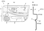
図1(a)は、本発明を適用して製造した樹脂成形品の一例として自動車用内装部品であるツートンタイプのドアトリムの正面図、同図(b)は、そのB−B断面図である。 FIG. 1A is a front view of a two-tone type door trim, which is an interior part for an automobile, as an example of a resin molded product manufactured by applying the present invention, and FIG. .
図1(a)のドアトリムDT(樹脂成形品1)は、ドアトリムアッパーDT1(第1樹脂成形体2)と、その端末部2Aに接合されているドアトリムロアDT2(第2樹脂成形体3)とからなる上下2分割体であって、ドアトリムアッパーDT1とドアトリムロアDT2の接合部4を境にドアトリムアッパーDT1とドアトリムロアDT2は色彩が異なるツートンタイプになっている。
A door trim DT (resin molded product 1) in FIG. 1A includes a door trim upper DT1 (first resin molded body 2) and a door trim lower DT2 (second resin molded body 3) joined to the
また、図1(a)のドアトリムDTは、後述する本発明の製造方法を適用して製造されることにより、同図(b)に示すように、ドアトリムアッパーDT1の端末部2Aにおける両面のうち意匠面Fとは反対の裏面R側に、ドアトリムロアDT2を形成している第2溶融樹脂が回り込んで固化した構造になっている(図5(b)、図7(b)、図9(b)参照)。
Further, the door trim DT of FIG. 1 (a) is manufactured by applying the manufacturing method of the present invention to be described later, so that, as shown in FIG. 1 (b), of the both surfaces of the
図1(a)のドアトリムDTでは、前記のような第2溶融樹脂の回り込み固化構造により、ドアトリムアッパーDT1の端末部2AとドアトリムロアDT2との接合面積が拡大され、接合強度の向上が図られている。これに加えて更に、図1(a)のドアトリムDTでは、後述する本発明を適用して製造されることにより、接合部4での樹脂漏れによる外観不良も効果的に防止されており、接合部4の見栄え向上も図られている。
In the door trim DT of FIG. 1A, the joining area between the
また、図1(a)を参照すると、ドアトリムアッパーDT1には、機能部品として、インサイドハンドルエスカッション5、パワーウインドウスイッチエスカッション6等が取り付けられている。また、ドアトリムロアDT2には、ドアポケット用開口7が開設されており、その背面側にはポケットバックカバー8が取り付けられている。ドアトリムロアDT2のフロント側には、スピーカグリル9が一体あるいは別体に形成されている。
Referring to FIG. 1A, the door trim upper DT1 is provided with an inside handle escutcheon 5 and a power window switch escutcheon 6 as functional parts. The door trim lower DT2 is provided with a
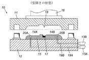
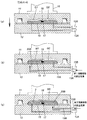
図2は、第1の本発明を適用して図1のドアトリム等の樹脂成形品を製造するための成形金型の概念図、図3(a)は、図1の成形金型における型締め工程とその型締め状態の説明図、図3(b)は、図1の成形金型における第1溶融樹脂の射出充填工程とその射出充填状態の説明図、図3(c)は、図1の成形金型における第2溶融樹脂の射出充填工程とその射出充填状態の説明図である。 FIG. 2 is a conceptual diagram of a molding die for manufacturing a resin molded product such as the door trim of FIG. 1 by applying the first present invention, and FIG. 3A is a mold clamping in the molding die of FIG. FIG. 3 (b) is an explanatory diagram of the first molten resin injection filling process and its injection filling state in the molding die of FIG. 1, and FIG. 3 (c) is FIG. It is explanatory drawing of the injection filling process of the 2nd molten resin in the molding die of, and its injection filling state.
図2の成形金型10は、所定ストローク長で上下動可能なキャビ型11と、このキャビ型11と対をなす固定のコア型12と、このコア型12に接続される2基の射出機(第1射出機13A、第2射出機13B)とを有している。
A molding die 10 in FIG. 2 includes a
キャビ型11の型面(コア型12と対向している面)には、2つの連続した凹形状のキャビティ14A、14Bが形成されている。図2の成形金型10ではキャビティ14A、14Bの凹面で最終製品としての樹脂成形品1の意匠面Fを成形するので、前記キャビティ14A、14Bの凹形状は、その樹脂成形品1の意匠面Fの形状に合致するように形成してある。
Two continuous
コア型12の型面(キャビ型11と対向している面)には、前記2つの連続した凹形状のキャビティ14A、14Bに対応する凸形状のコア15が設けられている。図2の成形金型10では前記コア15の凸面で最終製品としての樹脂成形品1の裏面R(意匠面Fと反対の面)を成形するので、コア15の凸形状は、その樹脂成形品1の裏面Rの形状に合致するように形成してある。
Convex-shaped
図2の成形金型10では、同図に示した油圧シリンダ16を利用してキャビ型11をコア型12に向って所定量下降させ、図3(a)のようにキャビ型11とコア型12の型締めを行うことにより、コア15とキャビティ14A、14Bを接近させ、キャビティ14A、14Bとコア15との間に樹脂成形品1を成形するための2つの連続した成形空間G1、G2が形成されるように構成してある。
In the molding die 10 of FIG. 2, the
前記2つの連続した成形空間G1、G2の境界部には、仕切り手段として、入子17が昇降可能に設けられている。図3(a)は入子17を最大に上昇させた状態である。このように入子17が最大に上昇した時に、前記2つの連続したキャビティ14A、14Bからその境界部に突出しているキャビティ内突部18と入子17とが当接することで、前記2つの連続した成形空間G1、G2は、その境界部で入子17により仕切られ、それぞれ独立した空間として設定される。なお、入子17を昇降させる手段としては、例えば公知の油圧シリンダ等を利用した図示しない昇降装置をコア型12に組み込む等の方式や、これ以外の方式を採用してよい。
A
図2の成形金型10では、図3(b)に示したように、入子17で仕切られた2つの成形空間G1、G2のうち一方の成形空間G1内に第1溶融樹脂M1を射出充填することにより、図3(c)のように第1樹脂成形体2が成形される。第1溶融樹脂M1の射出充填は第1射出機13Aにより行われる。第1射出機13Aは、図3(b)のようにコア型12に設けた第1マニホールド19Aと第1ゲート20Aを介して、前記一方の成形空間G1内に第1溶融樹脂M1を射出充填するものである。
In the molding die 10 of FIG. 2, as shown in FIG. 3B, the first molten resin M1 is injected into one molding space G1 of the two molding spaces G1 and G2 partitioned by the
また、図2の成形金型10では、図3(c)に示したように、図3(b)の位置にある入子17を所定量下降させることで当該入子17による仕切りを解除した後、前記2つの連続した成形空間G1、G2のうち他方の成形空間G2内に第2溶融樹脂M2を射出充填することで、前記2つの連続した成形空間G1、G2の境界部において第1樹脂成形体2の端末部2Aに接合してなる第2樹脂成形体3が成形される。第2溶融樹脂M2の射出充填は第2射出機13Bにより行われる。第2射出機13Bは、図3(c)のように、コア型12に設けた第2マニホールド19Bと第2ゲート20Bを介して、前記他方の成形空間G2内に第2溶融樹脂M2を射出充填するものである。
Further, in the molding die 10 of FIG. 2, as shown in FIG. 3C, the partition by the
前記のように第2樹脂成形体3を成形する工程では、第1樹脂成形体2の端末部2Aにおける両面のうちキャビ型11の型面との当接により形成される意匠面Fとは反対の裏面R側に、図5(a)に示すような空隙G3が設けられる。この空隙G3に第2樹脂成形体3を形成するための第2溶融樹脂M2が回り込んで固化することにより、第1樹脂成形体2の端末部2Aと第2樹脂成形体3との接合面積が拡大される。
In the step of molding the second resin molded
そして、第2樹脂成形体3を成形する工程では、前記空隙G3への第2溶融樹脂M2の流れ込み時に、第1樹脂成形体2の端末部2Aの位置を規制することにより、第2溶融樹脂M2が第1樹脂成形体2の意匠面Fに滲み出る現象、すなわち接合部4での樹脂漏れによる外観不良を効果的に防止することができる。
In the step of molding the second resin molded
次に、前記のように第1樹脂成形体の端末部の位置を規制する方式(以下「位置規制方式」という)について具体例を説明する。 Next, a specific example of the method for restricting the position of the terminal portion of the first resin molding as described above (hereinafter referred to as “position restricting method”) will be described.
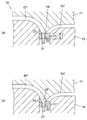
図4は、図2の成形金型に対し第1の位置規制方式を適用して樹脂成形品を製造する場合の説明図であり、同図(a)は、型締めの状態説明図、同図(b)は、型締め後に行われる第1溶融樹脂の射出充填時の状態説明図である。また、図5は、図2の成形金型に対し第1の位置規制方式を適用して樹脂成形品を製造する場合の説明図であり、同図(a)は、第1溶融樹脂の射出充填後に行われる第2溶融樹脂の射出充填時の状態説明図、同図(b)は、この第1の位置規制方式を採用した場合に最終製品として得られる樹脂成形品の断面図である。 FIG. 4 is an explanatory view when a resin molded product is manufactured by applying the first position regulation method to the molding die of FIG. 2, and FIG. 4 (a) is a state explanatory view of mold clamping, FIG. 2B is a state explanatory diagram at the time of injection filling of the first molten resin performed after the mold clamping. FIG. 5 is an explanatory view when a resin molded product is manufactured by applying the first position regulation method to the molding die of FIG. 2, and FIG. 5 (a) shows the injection of the first molten resin. A state explanatory diagram at the time of injection filling of the second molten resin performed after filling, FIG. 5B is a cross-sectional view of a resin molded product obtained as a final product when this first position regulation method is adopted.
第1の位置規制方式では、図4(a)のように、2つの連続した成形空間G1、G2の境界部には、コア型12に下端を固定してなる固定ピン21が設けられ、また、入子17には、第1樹脂成形体2の端末部2Aに向って開設された貫通孔22が設けられる。
In the first position regulation system, as shown in FIG. 4A, a fixing
図4(a)の工程は、先に説明した図3(a)の工程に対応するものである。この対応する図4(a)の工程では、キャビ型11とコア型12の型締めを行うとともに、入子17を所定量上昇させてキャビティ内突部18に当接させることにより、入子17で仕切られた2つの成形空間G1、G2を形成する。
The process in FIG. 4A corresponds to the process in FIG. 3A described above. In the corresponding step of FIG. 4A, the
図4(b)の工程は、先に説明した図3(b)の工程に対応するものである。この対応する図4(b)の工程では、前記のように入子17で仕切られた2つの成形空間G1、G2のうち一方の成形空間G1内に第1溶融樹脂M1を射出充填することで、第1樹脂成形体2を成形する。
The process of FIG. 4B corresponds to the process of FIG. 3B described above. In the corresponding step of FIG. 4B, the first molten resin M1 is injected and filled into one molding space G1 of the two molding spaces G1 and G2 partitioned by the
図5(a)の工程は、先に説明した図3(c)の工程に対応するものである。この対応する図5(a)の工程では、図4(b)の位置にある入子17を図5(a)のように所定量下降させて他方の成形空間G2に第2溶融樹脂M2を充填する。この時、図5(b)のように固定ピン21の上端が入子17の貫通孔22を通じて第1樹脂成形体2の端末部2Aに当接していることにより、その端末部2Aの位置が規制されるようになっている。このように固定ピン21で第1樹脂成形体2の端末部2Aの位置を規制する方式が、第1の位置規制方式である。
The process of FIG. 5A corresponds to the process of FIG. 3C described above. In the corresponding step of FIG. 5 (a), the
図6は、図2の成形金型に対し第2の位置規制方式を適用して樹脂成形品を製造する場合の説明図であり、同図(a)は、型締めの状態説明図、同図(b)は、型締め後に行われる第1溶融樹脂の射出充填時の状態説明図である。また、図7は、図2の成形金型に対し第2の位置規制方式を適用して樹脂成形品を製造する場合の説明図であり、同図(a)は、第1溶融樹脂の射出充填後に行われる第2溶融樹脂の射出充填時の状態説明図、同図(b)は、この第2の位置規制方式を採用した場合に最終製品として得られる樹脂成形品の断面図である。 FIG. 6 is an explanatory diagram when a resin molded product is manufactured by applying the second position regulation method to the molding die of FIG. 2, and FIG. FIG. 2B is a state explanatory diagram at the time of injection filling of the first molten resin performed after the mold clamping. FIG. 7 is an explanatory view when a resin molded product is manufactured by applying the second position regulating method to the molding die of FIG. 2, and FIG. 7 (a) shows the injection of the first molten resin. A state explanatory view at the time of injection filling of the second molten resin performed after filling, FIG. 5B is a cross-sectional view of a resin molded product obtained as a final product when this second position regulation method is adopted.
第2の位置制御方式でも、図6(a)のように、2つの連続した成形空間G1、G2の境界部には、コア型12に下端を固定してなる固定ピン21が設けられ、また、入子17には、第1樹脂成形体2の端末部2Aに向って開設された貫通孔22が設けられる。
Also in the second position control method, as shown in FIG. 6A, a fixing
図6(a)の工程は、先に説明した図3(a)の工程に対応するものである。この対応する図6(a)の工程では、キャビ型11とコア型12の型締めを行うとともに、入子17を所定量上昇させてキャビティ内突部18に当接させることにより、入子17で仕切られた2つの成形空間G1、G2を形成する。また、この図6(a)の工程では、入子17の貫通孔22に固定ピン21の上端を挿入し、上端の位置すなわち挿入量を入子17の厚みTの範囲内とすることにより、貫通孔22全体のうち固定ピン21の上端より上の範囲が一方の成形空間G1内に連通する凹部23として設定されるものとする。
The process in FIG. 6A corresponds to the process in FIG. 3A described above. In the corresponding step of FIG. 6A, the
図6(b)の工程は、先に説明した図3(b)の工程に対応するものである。この対応する図6(b)の工程では、入子17で仕切られた2つの成形空間G1、G2のうち一方の成形空間G1に第1溶融樹脂M1を射出充填する。そして、この図6(b)の工程においては、前記のように設定された凹部23に第1溶融樹脂M1が流れ込んで固化することにより、第1溶融樹脂M1の固化体からなる樹脂ボス24が第1樹脂成形体2の端末部2Aに一体に形成される。
The process in FIG. 6B corresponds to the process in FIG. 3B described above. In the corresponding step of FIG. 6B, the first molten resin M1 is injected and filled into one molding space G1 of the two molding spaces G1 and G2 partitioned by the
図7(a)の工程は、先に説明した図3(c)の工程に対応するものである。この対応する図7(a)の工程では、入子17を所定量下降させて他方の成形空間G2に第2溶融樹脂M2を充填する。この時、同図(a)のように前記樹脂ボス24の先端が入子17の凹部から抜け出ないこと、すなわち、前記樹脂ボス24の先端が入子17の凹部23(図6(a)参照)に係合していることにより、第1樹脂成形体2の端末部2Aの位置が規制されるようになっている。このように第1樹脂成形体2の端末部2Aに樹脂ボス24を形成するとともに、この樹脂ボス24を利用して第1樹脂成形体2の端末部2Aの位置を規制する方式が、第2の位置規制方式である。
The process in FIG. 7A corresponds to the process in FIG. 3C described above. In the corresponding step of FIG. 7A, the
以上説明した第1の位置制御方式と第2の位置制御方式とを比較すると、最終製品として得られる樹脂成形品の接合部の強度(接合強度)は、第2の位置制御方式の方が高くなる。これは、第2の位置制御方式では、図7(b)のように、第1樹脂成形体2の端末部2Aにおける意匠面Fとは反対の裏面R側に第2溶融樹脂M2が回り込んで固化することにより、第1樹脂成形体2の端末部2Aと第2樹脂成形体3との接合面積が拡大されることに加え、更に、樹脂ボス24が第2樹脂成形体3に食い込む形態で接合されるからである。このような樹脂ボス24の食い込みは、図5(b)のように第1の位置制御方式を採用した場合に最終製品として得られる樹脂成形品1には存在しない。
When the first position control method and the second position control method described above are compared, the strength (bonding strength) of the joint portion of the resin molded product obtained as the final product is higher in the second position control method. Become. In the second position control method, as shown in FIG. 7B, the second molten resin M2 wraps around the back surface R side opposite to the design surface F in the
図8(a)は、第2の本発明を適用して図1のドアトリム等の樹脂成形品を製造するための成形金型の概念、その成形金型のコア型に第1樹脂成形体をセットする工程とセット状態の説明図、同図(b)は、その成形金型における型締め工程と型締め状態の説明図である。また、図9(a)は、図8(a)の成形金型における第2溶融樹脂の射出充填工程とその射出充填状態の説明図、図9(b)は、図8(a)の成形金型で得られる樹脂成形品の断面図である。 FIG. 8A shows a concept of a molding die for manufacturing the resin molded product such as the door trim of FIG. 1 by applying the second present invention, and the first resin molded body is used as the core die of the molding die. The explanatory view of the setting process and the set state, (b) is an explanatory view of the clamping process and the clamping state in the molding die. FIG. 9 (a) is an explanatory view of the injection filling process and injection filling state of the second molten resin in the molding die of FIG. 8 (a), and FIG. 9 (b) is the molding of FIG. 8 (a). It is sectional drawing of the resin molded product obtained with a metal mold | die.
図8(a)の成形金型の基本的な構成、例えば、キャビ型11とコア型12の型締めにより2つの連続した成形空間G1、G2が形成されることや、これら2つの連続した成形空間G1、G2の境界部には、コア型12に下端を固定してなる固定ピン21が設けられていること等は、図4(a)や図6(a)の成形金型10と同様であるため、その詳細説明は省略する。図8(a)の成形金型10が図4(a)や図6(a)の成形金型10と異なるところは、入子17と第1射出機13Aが省略されている点である。
8A, two continuous molding spaces G1 and G2 are formed by clamping the
図8(a)の工程においては、第1溶融樹脂により予め成形した第1樹脂成形体2を用意し、それをコア型12にセットする。この際、後工程(図8(b)参照)の型締めで形成される2つの連続した成形空間G1、G2のうち一方の成形空間G1に第1樹脂成形体2が配置されるようにするため、第1樹脂成形体2のセット位置は図8(a)に示す位置とする。また、このセット位置において、第1樹脂成形体2の端末部2Aは図8(a)のように固定ピン21の上端に当接するように設定する。
In the process of FIG. 8A, the first resin molded
また、この図8(b)の工程では、第1樹脂成形体2の端末部2Aにおける両面のうちキャビ型11の型面との当接により形成される意匠面Fとは反対の裏面R側に、図8(a)に示すような空隙G3が設定される。
8B, the back surface R side opposite to the design surface F formed by contact with the mold surface of the
次に、図8(b)の工程では、キャビ型11をコア型12に向って所定量下降させることにより型締めを行っている。これにより、コア15とキャビティ14A、14Bが接近し、キャビティ14A、14Bとコア15との間に樹脂成形品を成形するための2つの連続した成形空間G1、G2(図4(a)、図6(a)参照)が形成される。これら2つの連続した成形空間G1、G2のうち一方の成形空間G1には、先の工程でセットした第1樹脂成形体2が配置されている。
Next, in the step of FIG. 8B, the mold is clamped by lowering the
なお、この型締め後も、前記空隙G3の設定や、第1樹脂成形体2の端末部2Aが固定ピン21の上端に当接している設定は、維持される。型締めにより固定ピン21の上端が第1樹脂成成形品2の端末部2Aをキャビ型11に向って押し付ける力は、固定ピン21の高さを変更することにより、適宜調整することができる。
Even after the mold clamping, the setting of the gap G3 and the setting where the
その後の図9(a)の工程では、前記2つの連続した成形空間G1、G2のうち他方の成形空間G2内に第2溶融樹脂M1を射出充填することで、前記2つの連続した成形空間G1、G2の境界部において第1樹脂成形体2の端末部2Aに接合してなる第2樹脂成形体3を成形する。
9A, the second molten resin M1 is injected and filled into the other molding space G2 of the two continuous molding spaces G1 and G2, so that the two continuous molding spaces G1 are injected. , The second resin molded
前記のように第2樹脂成形体3を成形する工程では、先に設定した空隙G3に第2樹脂成形体を形成するための第2溶融樹脂が回り込んで固化することにより、第1樹脂成形体の端末部と第2樹脂成形体との接合面積が拡大される。
In the step of molding the second resin molded
また、前記空隙G3への第2溶融樹脂の流れ込み時に、固定ピン21の上端が第1樹脂成形体2の端末部2Aに当接していることで、その端末部2Aの位置が規制される。これにより、第2溶融樹脂M2が第1樹脂成形体2の意匠面Fに滲み出る現象、すなわち接合部4での樹脂漏れによる外観不良を効果的に防止することができる。
Further, when the second molten resin flows into the gap G3, the upper end of the fixing
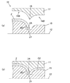
図10は、本発明の参考例である。この参考例では、第2樹脂成形体3を成形する工程において、第2溶融樹脂M2を射出充填する時に、第1樹脂成形体2の端末部2Aの位置を規制していない。このため、第2溶融樹脂M2の射出充填時において、空隙G3の存在により第1樹脂成形体2の端末部2Aがその厚み方向にフリーになるため、第2溶融樹脂M2の射出圧力により第1樹脂成形体2の端末部2Aが撓むことで、意匠面Fとキャビ型11との間に隙間ができ、第2溶融樹脂M2が第1樹脂成形体2の意匠面Fに滲み出る現象、すなわち接合部4での樹脂漏れによる外観不良が生じ易い。
FIG. 10 is a reference example of the present invention. In this reference example, in the step of molding the second resin molded
図2から図9では、キャビ型11とコア型12が上下に配置される例を示したが、この配置例に限定されることはない。本発明は、そのようなキャビ型11とコア型12が横に並んで配置される例にも適用することができる。
Although FIGS. 2 to 9 show examples in which the
本発明は、リヤパーセルシェルフ、フロアトリム、トランクトリム、リヤサイドトリム等、ドアトリム以外の自動車用内装部品に適用できることは勿論のこと、自動車用内装部品以外の樹脂成形品であって、かつ、第1樹脂成形体の端末部に第2樹脂成形体を接合した形態のものに適用してもよい。 The present invention can be applied to interior parts for automobiles other than door trims such as rear parcel shelves, floor trims, trunk trims, rear side trims, etc., and is a resin molded product other than interior parts for automobiles. You may apply to the form which joined the 2nd resin molding to the terminal part of the resin molding.
また、本発明は、以上説明した実施形態に限定されるものではなく、本発明の技術的思想内で当分野において通常の知識を有する者により多くの変形が可能である。 The present invention is not limited to the embodiments described above, and many modifications can be made by those having ordinary knowledge in the art within the technical idea of the present invention.
1 樹脂成形品
2 第1樹脂成形体
2A 第1樹脂成形体の端末部
3 第2樹脂成形体
4 接合部
5 インサイドハンドルエスカッション
6 パワーウインドウスイッチエスカッション
7 ドアポケット用開口
8 ポケットバックカバー
9 スピーカグリル
10 成形金型
11 キャビ型
12 コア型
13A 第1射出機
13B 第2射出機
14A 一方のキャビティ
14B 他方のキャビティ
15 コア
16 油圧シリンダ
17 入子
18 キャビティ内突部
19A 第1マニホールド
19B 第2マニホールド
20A 第1ゲート
20B 第2ゲート
21 固定ピン
22 貫通孔
23 凹部
DT ドアトリム(樹脂成形品)
DT1 ドアトリムアッパー(第1樹脂成形体)
DT2 ドアトリムロア(第2樹脂成形体)
E 樹脂成形品
F 樹脂成形品の意匠面
R 樹脂成形品の裏面
G1 一方の成形空間
G2 他方の成形空間
G3 空隙
M1 第1溶融樹脂
M2 第2溶融樹脂
DESCRIPTION OF
DT1 Door trim upper (first resin molding)
DT2 Door trim lower (second resin molding)
E Resin molded product F Design surface R of resin molded product Rear surface G1 of resin molded product One molding space G2 The other molding space G3 Gap M1 First molten resin M2 Second molten resin
Claims (3)
キャビ型とコア型の型締めによって形成される2つの連続した成形空間の境界部を入子で仕切り、仕切られた2つの成形空間のうち一方の成形空間内に第1溶融樹脂を射出充填することで、第1樹脂成形体を形成する工程と、
前記入子を所定量下降させることで当該入子による仕切りを解除した後、前記2つの連続した成形空間のうち他方の成形空間内に第2溶融樹脂を射出充填することで、前記2つの連続した成形空間の境界部において前記第1樹脂成形体の端末部に接合してなる第2樹脂成形体を成形する工程と、を含み、
前記第2樹脂成形体を成形する工程では、前記第1樹脂成形体の端末部における両面のうち前記キャビ型の型面との当接により形成される意匠面とは反対の裏面側に空隙を設け、この空隙に前記第2樹脂成形体を形成するための第2溶融樹脂が回り込んで固化することにより、前記第1樹脂成形体の端末部と前記第2樹脂成形体との接合面積を拡大してなること、及び、前記空隙への第2溶融樹脂の流れ込み時に、下記《位置規制構造》で前記第1樹脂成形体の端末部の位置を規制してなること
を特徴とする樹脂成形品の製造方法。
《位置規制構造》
前記2つの連続した成形空間の境界部には、前記コア型に下端を固定してなる固定ピンが設けられ、前記入子には、前記第1樹脂成形体の端末部に向って開設された貫通孔が設けられており、前記入子を所定量下降させて前記他方の成形空間に第2溶融樹脂を充填する時は、前記固定ピンの上端が前記入子の貫通孔を通じて前記第1樹脂成形体の端末部に当接していることにより、その端末部の位置が規制されるようになっている。 A method for producing a resin molded product in a form in which a second resin molded body is joined to a terminal portion of a first resin molded body,
A boundary portion between two continuous molding spaces formed by clamping the mold of the mold and the core mold is partitioned with a nest, and the first molten resin is injected and filled into one of the two molding spaces. The process of forming the first resin molded body,
After releasing the partition by the predetermined amount by lowering the nest, the second continuous resin is injected and filled into the other molding space of the two continuous molding spaces. Forming a second resin molded body formed by bonding to the terminal portion of the first resin molded body at the boundary portion of the molded space,
In the step of molding the second resin molded body, a gap is formed on the back surface side opposite to the design surface formed by contact with the mold surface of the mold, out of both surfaces of the terminal portion of the first resin molded body. Provided, and the second molten resin for forming the second resin molded body wraps around and solidifies in the gap, thereby reducing the bonding area between the terminal portion of the first resin molded body and the second resin molded body. Resin molding characterized in that it is enlarged and the position of the terminal portion of the first resin molded body is regulated by the following << position regulating structure >> when the second molten resin flows into the gap. Product manufacturing method.
《Position control structure》
A fixing pin formed by fixing a lower end to the core mold is provided at a boundary portion between the two continuous molding spaces, and the insert is opened toward the terminal portion of the first resin molded body. When a through hole is provided and when the insert is lowered by a predetermined amount to fill the other molding space with the second molten resin, the upper end of the fixing pin passes through the insert hole of the insert. By contacting the terminal portion of the molded body, the position of the terminal portion is regulated.
キャビ型とコア型の型締めによって形成される2つの連続した成形空間の境界部を入子で仕切り、仕切られた2つの成形空間のうち一方の成形空間内に第1溶融樹脂を射出充填することで、第1樹脂成形体を形成する工程と、
前記入子を所定量下降させることで当該入子による仕切りを解除した後、前記2つの連続した成形空間のうち他方の成形空間内に第2溶融樹脂を射出充填することで、前記2つの連続した成形空間の境界部において前記第1樹脂成形体の端末部に接合してなる第2樹脂成形体を成形する工程と、を含み、
前記第2樹脂成形体を成形する工程では、前記第1樹脂成形体の端末部における両面のうち前記キャビ型の型面との当接により形成される意匠面とは反対の裏面側に空隙を設け、この空隙に前記第2樹脂成形体を形成するための第2溶融樹脂が回り込んで固化することにより、前記第1樹脂成形体の端末部と前記第2樹脂成形体との接合面積を拡大してなること、及び、前記空隙への第2溶融樹脂の流れ込み時に、下記《位置規制構造》で前記第1樹脂成形体の端末部の位置を規制してなること
を特徴とする樹脂成形品の製造方法。
《位置規制構造》
前記2つの連続した成形空間の境界部には、前記コア型に下端を固定してなる固定ピンが設けられ、前記入子には、前記第1樹脂成形体の端末部に向って開設された貫通孔が設けられており、
前記第1溶融樹脂の射出充填時には、前記入子の前記貫通孔に前記固定ピンの上端を挿入し、その挿入量を前記入子の厚み範囲内とすることにより、前記貫通孔全体のうち当該固定ピンの上端より上の範囲が前記一方の成形空間内に連通する凹部として設定されるとともに、その凹部に前記第1溶融樹脂が流れ込んで固化することにより、第1溶融樹脂からなる樹脂ボスが前記第1樹脂成形体の端末部に一体に形成されてなり、
前記入子を所定量下降させて前記他方の成形空間に第2溶融樹脂を充填する時は、前記樹脂ボスの先端が前記入子の前記凹部から抜け出ないことにより、前記第1樹脂成形体の端末部の位置が規制されるようになっている。 A method for producing a resin molded product in a form in which a second resin molded body is joined to a terminal portion of a first resin molded body,
A boundary portion between two continuous molding spaces formed by clamping the mold of the mold and the core mold is partitioned with a nest, and the first molten resin is injected and filled into one of the two molding spaces. The process of forming the first resin molded body,
After releasing the partition by the predetermined amount by lowering the nest, the second continuous resin is injected and filled into the other molding space of the two continuous molding spaces. Forming a second resin molded body formed by bonding to the terminal portion of the first resin molded body at the boundary portion of the molded space,
In the step of molding the second resin molded body, a gap is formed on the back surface side opposite to the design surface formed by contact with the mold surface of the mold, out of both surfaces of the terminal portion of the first resin molded body. Provided, and the second molten resin for forming the second resin molded body wraps around and solidifies in the gap, thereby reducing the bonding area between the terminal portion of the first resin molded body and the second resin molded body. Resin molding characterized in that it is enlarged and the position of the terminal portion of the first resin molded body is regulated by the following << position regulating structure >> when the second molten resin flows into the gap. Product manufacturing method.
《Position control structure》
A fixing pin formed by fixing a lower end to the core mold is provided at a boundary portion between the two continuous molding spaces, and the insert is opened toward the terminal portion of the first resin molded body. A through hole is provided,
At the time of injection filling of the first molten resin, the upper end of the fixing pin is inserted into the through hole of the insert, and the insertion amount is within the thickness range of the insert, so that A range above the upper end of the fixing pin is set as a concave portion communicating with the one molding space, and the first molten resin flows into the concave portion and solidifies, whereby a resin boss made of the first molten resin is formed. Formed integrally with the terminal portion of the first resin molding,
When the nest is lowered by a predetermined amount and the other molding space is filled with the second molten resin, the tip of the resin boss does not come out of the concave portion of the nest so that the first resin molded body The position of the terminal unit is regulated.
キャビ型とコア型の型締めによって形成される2つの連続した成形空間のうち一方の成形空間内に予め成形した第1樹脂成形体をセットする工程と、
前記2つの連続した成形空間のうち他方の成形空間内に第2溶融樹脂を射出充填することで、前記2つの連続した成形空間の境界部において前記第1樹脂成形体の端末部に接合してなる第2樹脂成形体を成形する工程と、を含み、
前記第2樹脂成形体を成形する工程では、前記第1樹脂成形体の端末部における両面のうち前記キャビ型の型面との当接により形成される意匠面とは反対の裏面側に空隙を設け、この空隙に前記第2樹脂成形体を形成するための第2溶融樹脂が回り込んで固化することにより、前記第1樹脂成形体の端末部と前記第2樹脂成形体との接合面積を拡大してなること、及び、前記第2溶融樹脂の射出充填時に、下記《位置規制構造》で前記第1樹脂成形体の端末部の位置を規制してなること
を特徴とする樹脂成形品の製造方法。
《位置規制構造》
前記2つの連続した成形空間の境界部には、前記コア型に下端を固定してなる固定ピンが設けられており、
前記他方の成形空間に第2溶融樹脂を充填する時は、前記固定ピンの上端が前記第1樹脂成形体の端末部の先端面に当接していることにより、その端末部の先端面が支持されるとともに、その端末部の位置が規制されるようになっている。
A method for producing a resin molded product in a form in which a second resin molded body is joined to a terminal portion of a first resin molded body,
A step of setting a pre-molded first resin molded body in one of the two continuous molding spaces formed by clamping the mold and the core mold;
The second molten resin is injected and filled into the other molding space of the two continuous molding spaces, thereby joining the terminal portion of the first resin molded body at the boundary between the two continuous molding spaces. Forming a second resin molded body comprising:
In the step of molding the second resin molded body, a gap is formed on the back surface side opposite to the design surface formed by contact with the mold surface of the mold, out of both surfaces of the terminal portion of the first resin molded body. Provided, and the second molten resin for forming the second resin molded body wraps around and solidifies in the gap, thereby reducing the bonding area between the terminal portion of the first resin molded body and the second resin molded body. And the position of the terminal portion of the first resin molded body is regulated by the following << position regulating structure >> at the time of injection filling of the second molten resin. Production method.
《Position control structure》
A fixing pin formed by fixing a lower end to the core mold is provided at a boundary portion between the two continuous molding spaces,
When filling the other molding space with the second molten resin, the upper end of the fixing pin is in contact with the distal end surface of the end portion of the first resin molded body, so that the distal end surface of the end portion is supported. In addition, the position of the terminal portion is regulated.
Priority Applications (1)
| Application Number | Priority Date | Filing Date | Title |
|---|---|---|---|
| JP2011230593A JP5804635B2 (en) | 2011-10-20 | 2011-10-20 | Manufacturing method of resin molded products |
Applications Claiming Priority (1)
| Application Number | Priority Date | Filing Date | Title |
|---|---|---|---|
| JP2011230593A JP5804635B2 (en) | 2011-10-20 | 2011-10-20 | Manufacturing method of resin molded products |
Publications (2)
| Publication Number | Publication Date |
|---|---|
| JP2013086414A JP2013086414A (en) | 2013-05-13 |
| JP5804635B2 true JP5804635B2 (en) | 2015-11-04 |
Family
ID=48530828
Family Applications (1)
| Application Number | Title | Priority Date | Filing Date |
|---|---|---|---|
| JP2011230593A Expired - Fee Related JP5804635B2 (en) | 2011-10-20 | 2011-10-20 | Manufacturing method of resin molded products |
Country Status (1)
| Country | Link |
|---|---|
| JP (1) | JP5804635B2 (en) |
Family Cites Families (2)
| Publication number | Priority date | Publication date | Assignee | Title |
|---|---|---|---|---|
| JPH0241221A (en) * | 1988-08-01 | 1990-02-09 | Daikyo Inc | Double injection molding method |
| JP5235470B2 (en) * | 2008-03-31 | 2013-07-10 | ダイハツ工業株式会社 | Injection mold and injection molding method |
-
2011
- 2011-10-20 JP JP2011230593A patent/JP5804635B2/en not_active Expired - Fee Related
Also Published As
| Publication number | Publication date |
|---|---|
| JP2013086414A (en) | 2013-05-13 |
Similar Documents
| Publication | Publication Date | Title |
|---|---|---|
| KR100969120B1 (en) | Dichroic injection molding mold and molding method | |
| US9138922B2 (en) | Load bearing panel member | |
| JP2015009449A (en) | Injection molding method and resin molded product | |
| CN104842500B (en) | Method and mold for producing openings in fiber composite parts | |
| ITTO20000443A1 (en) | PROCESS AND EQUIPMENT FOR THERMOCOMPRESSION MOLDING OF ARTICLES OF THERMOPLASTIC MATERIAL. | |
| JP5804635B2 (en) | Manufacturing method of resin molded products | |
| JP2019195989A (en) | Method of manufacturing model car body and model car body made of plastic | |
| JP5648565B2 (en) | Multicolor molded product manufacturing method and mold | |
| JP6465006B2 (en) | Reinforcing structure for vehicle back door inner part and method for manufacturing the same | |
| US9533442B2 (en) | Injection mold and method of producing molded resin article | |
| JP2006289794A (en) | Mold for in-mold coating molding and in-mold coating molding method | |
| JP2788670B2 (en) | Resin hollow molding | |
| JP2005193634A (en) | Manufacturing method of injection molded body and mold apparatus therefor | |
| JP6649872B2 (en) | Door handle molding method | |
| JP3611977B2 (en) | Method for molding hollow body product and mold for molding | |
| JP4476673B2 (en) | Mold for foam molding | |
| JP4405870B2 (en) | Insert molding die, insert molded body, and method of manufacturing insert molded body | |
| JP2596660B2 (en) | Joint structure of bumper reinforcement | |
| JP4812033B2 (en) | Method for molding composite molded article and molding die | |
| JP5909465B2 (en) | Injection mold and method for producing resin molded product | |
| CN113370461A (en) | Injection molding manufacturing method for glasses legs | |
| JP6322018B2 (en) | Injection mold and method of manufacturing resin molded product using the same | |
| JP2012232508A (en) | Method of manufacturing multicolor molded article, and molding die | |
| CN111016105B (en) | Insert molding method and device | |
| US8337745B2 (en) | Integral molten evacuation channel |
Legal Events
| Date | Code | Title | Description |
|---|---|---|---|
| A621 | Written request for application examination |
Free format text: JAPANESE INTERMEDIATE CODE: A621 Effective date: 20130830 |
|
| A977 | Report on retrieval |
Free format text: JAPANESE INTERMEDIATE CODE: A971007 Effective date: 20140716 |
|
| A131 | Notification of reasons for refusal |
Free format text: JAPANESE INTERMEDIATE CODE: A131 Effective date: 20140722 |
|
| A521 | Request for written amendment filed |
Free format text: JAPANESE INTERMEDIATE CODE: A523 Effective date: 20140918 |
|
| A131 | Notification of reasons for refusal |
Free format text: JAPANESE INTERMEDIATE CODE: A131 Effective date: 20150305 |
|
| A521 | Request for written amendment filed |
Free format text: JAPANESE INTERMEDIATE CODE: A523 Effective date: 20150416 |
|
| TRDD | Decision of grant or rejection written | ||
| A01 | Written decision to grant a patent or to grant a registration (utility model) |
Free format text: JAPANESE INTERMEDIATE CODE: A01 Effective date: 20150831 |
|
| A61 | First payment of annual fees (during grant procedure) |
Free format text: JAPANESE INTERMEDIATE CODE: A61 Effective date: 20150831 |
|
| R150 | Certificate of patent or registration of utility model |
Ref document number: 5804635 Country of ref document: JP Free format text: JAPANESE INTERMEDIATE CODE: R150 |
|
| LAPS | Cancellation because of no payment of annual fees |